basic equipment and components general
TRANSCRIPT

PART TWO
Masonry
7-1. The original idea of masonry was nothing more than placing stones in an orderly fashion normally by
laying them in rows. As time continued, with improved quality and type of materials available, this
orderly lying of stone has progressed into laying them with the use of masonry cements that bonds them
together. Part two of this manual covers basic tools and equipment, properties, and mixing of mortar.
Concrete masonry will include the characteristics of concrete blocks, construction procedures, and rubble
stone masonry. The characteristics of brick, and brick laying methods are discussed in the final chapter.
Chapter 7
Basic Equipment and Components General
7-2. Many of the longest-lasting structures in the world are constructed with masonry
materials, such as stones, bricks, or blocks. Masons are highly skilled people who use
specialized equipment to lay out and construct masonry walls and other building features.
Along with erecting these structures, masons are responsible for the care of their tools and
equipment. They are also responsible for the correct mixing proportions of the mortar and the
safe erection of scaffolding.
SECTION I. MASON'S TOOLS AND EQUIPMENT
DEFINITION
7-3. Masonry originally meant the art of building a structure from stone. Today, masonry
means to build a structure from any building materials, such as, concrete blocks, stones,
bricks, clay tile products, gypsum blocks, and sometimes glass blocks, that consist of units
held together with mortar; The characteristics of masonry work are determined by the
properties of the masonry units and mortar, and the methods of bonding, reinforcing,
anchoring, tying, and joining the units into a structure.
FM 5-428 Chptr 7 Masonry
7-1

TOOLS
7-4. Figure 7-1 shows a set of typical basic mason's tools. Care of the tools are extremely
necessary. Be sure to keep wheelbarrows, mortar boxes, and mortar tools clean because
hardened mortar is difficult to remove. Clean all tools and equipment thoroughly at the end of
each day or when the job is finished. A full set includes--
A trowel. A trowel is used to mix and pick up mortar from the board, to place mortar
on the unit, to spread mortar, and to tap the unit down into the bed. A common trowel
is usually triangular in shape ranging in size up to about 11 inches long and from 4 to 8
inches wide. Its length and weight depend on the mason. Generally, short, wide trowels
are best because they do not put too much strain on the wrist. Trowels used to point
and strike joints are smaller, ranging from 3 to 6 inches long and 2 to 3 inches wide.
●
A chisel or bolster. A chisel is used to cut masonry units into parts. A typical chisel is 2
1/2 to 4 1/2 inches wide.
●
A hammer. The mason's hammer has a square face on one end and a long chisel peen
on the other. It weighs from 1 1/2 to 3 1/2 pounds. It is used to split and rough-break
masonry units.
●
A jointer. As its name implies, this tool is used to make various mortar joints. There
are several different types of jointer-rounded, flat, or pointed, depending on the shape
of the mortar joint you want.
●
A square. The square that is shown in Figure 7-2 below is used to measure right angles
and to lay out corners.
●
A mason's level. The level is used to plumb and level walls. A level ranges from 42 to
48 inches in length and is made from either wood or metal. Figure 7-2 shows a level in
both the horizontal and vertical positions. When you place it on the masonry
horizontally and the bubble falls exactly in the middle of the center tube, the masonry
is level. When you place the level against the masonry vertically and the bubbles fall
exactly in the middle of the two end tubes, the masonry is plumb.
●
A straightedge. A straightedge, shown in Figure 7-2, can be any length up to 16 feet,
from 1 1/8 inches to 1 1/2 inches thick, and the middle portion of the top edge from 6
to 10 inches wide. The middle portion of the top edge must be parallel to the bottom
edge. Use a straightedge to extend a level to either plumb or level distances longer than
the level length.
●
Miscellaneous tools. Other mason's tools and equipment include shovels, mortar hoes,
wheelbarrows, chalk lines, plumb bobs, and a 200-foot ball of good quality mason's
line.
●
FM 5-428 Chptr 7 Masonry
7-2

Figure 7-1. Basic Mason's Tools
FM 5-428 Chptr 7 Masonry
7-3
EQUIPMENT
7-5. Mortar is mixed by hand in a mortar box. It should be as watertight as possible. A mortar
board (see Figure 7-3) can range from 3 to 4 feet square. Wet down a mortar board
thoroughly before placing any mortar on it to prevent the wood from drying it out and
absorbing moisture from the mortar. Figure 7-3 shows the proper way to fill a mortar board.
Note the mounds of mortar in the center of the board; this minimizes drying. After filling the

Figure 7-2. Square, mason's level, and straightedge
FM 5-428 Chptr 7 Masonry
7-4
mortar board, keep the mortar rounded up in the center of the board and the outer edges of the
board clean. Any mortar spread in a thin layer dries out quickly, and lumps form in it. Be sure
to maintain the proper mortar consistency at all times.

FM 5-428 Chptr 7 Masonry
7-5
Figure 7-3. Motar Box and mortar board

SECTION II. MORTAR
DESIRABLE PROPERTIES
7-6. Good mortar is necessary for good workmanship and good masonry service because it
must bond the masonry units into a strong well-knit structure.
BOND CONSIDERATIONS
7-7. The mortar that bonds concrete blocks,bricks, or clay tiles together will be the weakest
part of the masonry unless you mix and apply it properly. When masonry leaks are
encountered, they are usually through the mortar joints. The strength of masonry and its
resistance to rain penetration depends largely on the strength of the bond between the
masonry unit and the mortar. Various factors affect bond strength including the type and
quantity of mortar, its workability or plasticity, its water retentivity, the surface texture of the
mortar bed, and the quality of workmanship in laying the units. You can correct irregular
brick dimensions and shape with a good mortar joint.
PLASTICITY
7-8. Mortar must be flexible enough to work with a trowel. You can obtain good plasticity or
workability by-
Using mortar having good water retentivity.●
Using the proper grade of sand and thoroughly mixing.●
Using less cementitious materials.●
Mortar properties depend largely upon the type of sand the mortar contains. Clean, sharp sand
produces excellent mortar; too much sand causes mortar to segregate, drop off the trowel, and
weather poorly.
WATER RETENTIVITY
7-9. Mortar property resists rapid water loss to highly absorbent masonry units. Mortar must
have water to develop the bond. If it does not contain enough water, the mortar will have poor
plasticity and workability and the bond will be weak and spotty. Sometimes you must wet the
brick to control water absorption before applying mortar, but never wet concrete masonry
units.
STRENGTH AND DURABILITY
7-10. The type of service that the masonry must give determines the mortar's strength and
durability requirements. For example, walls subject to severe stresses or to severe weathering
FM 5-428 Chptr 7 Masonry
7-6
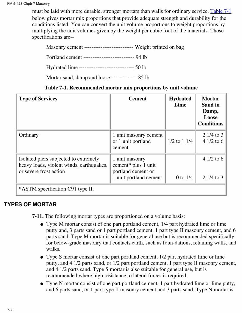
must be laid with more durable, stronger mortars than walls for ordinary service. Table 7-1
below gives mortar mix proportions that provide adequate strength and durability for the
conditions listed. You can convert the unit volume proportions to weight proportions by
multiplying the unit volumes given by the weight per cubic foot of the materials. Those
specifications are--
Masonry cement --------------------------- Weight printed on bag
Portland cement ---------------------------- 94 lb
Hydrated lime ------------------------------ 50 lb
Mortar sand, damp and loose -------------- 85 lb
Table 7-1. Recommended mortar mix proportions by unit volume
Type of Services Cement Hydrated
Lime
Mortar
Sand in
Damp,
Loose
Conditions
Ordinary 1 unit masonry cement
or 1 unit portland
cement
1/2 to 1 1/4
2 1/4 to 3
4 1/2 to 6
Isolated piers subjected to extremely
heavy loads, violent winds, earthquakes,
or severe frost action
1 unit masonry
cement* plus 1 unit
portland cement or
1 unit portland cement 0 to 1/4
4 1/2 to 6
2 1/4 to 3
*ASTM specification C91 type II.
TYPES OF MORTAR
7-11. The following mortar types are proportioned on a volume basis:
Type M mortar consist of one part portland cement, 1/4 part hydrated lime or lime
putty and, 3 parts sand or 1 part portland cement, 1 part type II masonry cement, and 6
parts sand. Type M mortar is suitable for general use but is recommended specifically
for below-grade masonry that contacts earth, such as foundations, retaining walls, and
walks.
●
Type S mortar consist of one part portland cement, 1/2 part hydrated lime or lime
putty, and 4 1/2 parts sand, or 1/2 part portland cement, 1 part type II masonry cement,
and 4 1/2 parts sand. Type S mortar is also suitable for general use, but is
recommended where high resistance to lateral forces is required.
●
Type N mortar consist of one part portland cement, 1 part hydrated lime or lime putty,
and 6 parts sand, or 1 part type II masonry cement and 3 parts sand. Type N mortar is
●
FM 5-428 Chptr 7 Masonry
7-7

suitable for general use in above- grade exposed masonry where high compressive
and/or lateral strengths are not required.
Type O mortar consist of one part portland cement, 2 parts hydrated lime or lime putty,
and 9 parts sand, or 1 part type I or type II masonry cement and 3 parts sand. Type O
mortar is recommended for load-bearing, solid-unit walls when the compressive
stresses do not exceed 100 psi, and the masonry is not subject to freezing and thawing
in the presence of a lot of moisture.
●
STORING MORTAR MATERIALS
7-12. Store all mortar materials, except sand and slaked quicklime, in a dry place. Sand and
lime should be covered to prevent excessive losses or gains of surface moisture.
MIXING MORTAR
7-13. When blending or mixing mortar, always use the best consistency for the job.
MACHINE MIXING
7-14. Mix large quantities of mortar in a drum-type mixer, like a concrete mixer. Mix a
minimum of 3 minutes. Place all dry ingredients in the mixer first, mix them for 1 minute
before adding the water.
HAND MIXING
7-15. Mix small amounts of mortar by hand in a mortar box (see Figure 7-3). Mix all
ingredients thoroughly to obtain a uniform mixture. Mix all dry materials together first before
adding water. Keep a steel drum of water close to the mortar box to use as the water supply.
Use a second drum of water to store shovels and hoes when not in use.
MORTAR MIXING WITH LIME PUTTY
7-16. When machine mixing, measure the lime putty using a pail and place it into the skip on
top of the sand. When hand mixing, add the sand to the lime putty. Wet pails before placing
mortar in them and clean them immediately after emptying them.
WATER QUALITY
7-17. Mixing water for mortar must meet the same requirements as mixing water for
concrete. Do not use water containing large amounts of dissolved salts, because the salts will
cause efflorescence and weaken the mortar.
RETEMPERING MORTAR
7-18. The workability of any mortar that stiffens on the mortar board due to evaporation by
remixing can be restored. Add water as necessary, but discard any mortar stiffened by initial
setting. It is difficult to tell the cause of stiffening; a practical guide is to use mortar within 2
FM 5-428 Chptr 7 Masonry
7-8

1/2 hours after the original mixing when the air temperature is 80°F or higher, and within 3
1/2 hours when the air temperature is below 80°F. Discard any mortar not used within these
limits.
ANTIFREEZE MATERIALS
7-19. Do not use an admixture to lower the freezing point of mortar during winter
construction. The quantity of antifreeze materials necessary to lower the freezing point of
mortar to any appreciable degree is so large that it would seriously impair the mortar's
strength and other desirable properties. Never use frozen mortar; freezing destroys its
bonding ability.
ACCELLERATORS
7-20. Make a trial mix to find the percentage of calcium chloride that gives the desired
hardening rate. Do not add more than 2 percent calcium chloride, by weight of cement to
mortar, to accelerate its hardening rate and increase early strength. Do not add more than 1
percent calcium chloride to masonry cements. Calcium chloride should not be used for
steel-reinforced masonry. You can also accelerate hardening rate in mortars with
high-early-strength portland cement.
REPAIRING AND TUCK-POINTING
7-21. Use the mortar mixes given in Table 7-1 when repairing and tuck-pointing old masonry
walls. Compact the joints thoroughly by tooling after the mortar partially stiffens.
SECTION III. SCAFFOLDING
CONSTRUCTION AND SAFETY
7-22. Extreme care should be taken in building scaffolds because lives depend on them. Use
rough lumber for wood scaffolding. Never nail scaffolding in a temporary manner; always
nail it securely. When you no longer need the planks at a lower level, remove them to avoid
falling mortar splash.
TYPES OF SCAFFOLDING
7-23. A scaffold is a temporary, movable platform built with planks to support workers and
materials. It allows bricklayers to work at heights not reachable when standing on the floor or
ground. Scaffolds can be used in several functions and come in different sizes and heights.
TRESTLE SCAFFOLD
7-24. Use a trestle scaffold shown in Figure 7-4 when laying bricks from the inside of a wall.
Erect the scaffold when the wall reaches a height of 4 or 5 feet. The height of the trestles
should range from 4 to 4 1/2 feet. The planks should be made using 2 by l0s. Place the trestle
at least 3 inches from the wall so that it does not press against the newly laid bricks and force
FM 5-428 Chptr 7 Masonry
7-9

them out of line. Build the wall to the next floor level working from the scaffold. When the
rough flooring for the next floor is in place, repeat the procedure.
Figure 7-4. Trestle scaffold
FOOT SCAFFOLD
7-25. When reaching lower than a trestle scaffold permits, use a foot scaffold like the one
shown in Figure 7-5. Place 2 by 10 planks on blocks supported by the trestle scaffold. A foot
scaffold should not exceed 18 inches in height.
Figure 7-5. Foot scaffold
PUTLOG SCAFFOLD
7-26. A putlog scaffold (see Figure 7-6) reaches from the ground to the height required. Its
uprights are 4 by 4s supported on a 2 by 12 by 12 plank for bearing on the soil. Space the
FM 5-428 Chptr 7 Masonry
7-10

uprights on 8-foot centers and allow 4 1/2 feet of space between the wall and the uprights, as
shown in Figure 7-6. The putlog is 3-by 4-inch lumber that spans the gap between the wall
and the ledger. One end of the putlog rests on top of the ledger and against the 4 by 4
uprights, while the other end fits into the wall (one brick is omitted to make an opening for
it). Do not fasten the putlog to the ledger. Place five 2 by 12 planks on top of the putlog to
form the scaffold platform. Do not nail the planks to the putlog. Two ways to use stays are-
Tie the uprights to the wall with stays. You can either pass the stays through a window
opening and fasten them to the inside structure or use spring stays as shown in Figure
7-6. To make spring stays, omit one brick from the wall and insert the ends of two 2 by
6s in the opening. Then insert a brick between the 2 by 6s and force the brick toward
the wall. Bring the other ends of the 2 by 6s together and nail them securely to the
ledger.
●
Use the putlog as a stay. You can also use the putlog as a stay by driving a wood
wedge above the putlog into its hole in the wall. Then, nail the wedge to the putlog and
nail the putlog to the ledger. Install longitudinal cross bracing as shown in Figure 7-6.
●
Figure 7-6. Putlog scaffold
OUTRIGGER SCAFFOLD
7-27. An outrigger scaffold (see Figure 7-7) consists of a wood outrigger beam projecting
from a window sill that supports 2 by 10 planks. Figure 7-7 shows how to brace a wood
beam, but if you use a steel outrigger beam, fasten it to the structure's formwork using
threaded U-bolts.
FM 5-428 Chptr 7 Masonry
7-11

Figure 7-7. Outrigger scaffold
PREFABRICATED STEEL SCAFFOLD
7-28. If it is available, use prefabricated steel scaffolding (see Figure 7-8) rather than building
a scaffold.
FM 5-428 Chptr 7 Masonry
7-12

Figure 7-8. Prefabricated steel scaffold
MATERIALS TOWER
7-29. Use a steel material tower if construction details are available because it is easier to
erect and generally safer. Otherwise, you can construct a wood tower to hoist materials to the
working height, like the one shown in Figure 7-9. Locate the tower where you can bring
materials to it over the shortest haul, but far enough away from the structure to clear any
external scaffolding. A clearance of 6 feet 8 inches is enough for scaffold platforms 5 feet
wide. Construct the tower footing using two 2 by 12s, 2 feet long, placed under each 4 by 4
post. The height of the tower should extend at least 15 feet above the highest point where you
need a landing. Then construct landings extending from the tower to the floors and scaffold
platforms as needed. Use 2 by 10s or 2 by 12s for the landings.
FM 5-428 Chptr 7 Masonry
7-13

Figure 7-9. Materials tower and elevator
FM 5-428 Chptr 7 Masonry
7-14

ELEVATOR
7-30. Figure 7-9 also shows the elevator, rope, and pulley arrangement that serves the
materials tower. Note the guides at the base of the elevator that fit onto the guides running up
from the base of the tower.
FM 5-428 Chptr 7 Masonry
7-15

Chapter 8
Concrete Masonry
8-1. When portland cement, water, and suitable aggregates, such as sand, gravel, crushed
stone, cinders, burned shale, or slag, are mixed and formed into individual pieces to be used
in laying up walls and other structural details, the pieces thus formed are known as unit
masonry, or units. However, most masons refer to them as concrete blocks. Concrete blocks
will vary in size and shape as well as style. They are typically used for house foundations,
decorative blocks for strong garden, or retaining walls. Rubble stone masonry is strong,
durable, and offers an incomparable beauty and range of effect. Construction of concrete
masonry is time consuming and requires highly skilled personnel.
SECTION I. CHARACTERISTICS OF CONCRETE BLOCK
NATURE AND PHYSICAL PROPERTIES
8-2. A concrete block is a masonry unit that either contains single or multiple hollows, or is
solid. It is made from conventional cement mixes and various types of aggregate, including
sand, gravel, crushed stone, air-cooled slag, coal cinders, expanded shale or clay, expanded
slag, volcanic cinders (pozzolan), pumice, and scoria (refuse obtained from metal ore
reduction and smelting). The term concrete blocks was formerly limited to only hollow
masonry units made with such aggregates as sand, gravel, and crushed stone. But today the
term covers all types of concrete blocks (both hollow and solid) made with any kind of
aggregate. Concrete blocks are also available with applied glazed surfaces, various pierced
designs, and a wide variety of surface textures. Although a concrete block is made in many
sizes and shapes (see Figure 8-1 below) and in both modular and nonmodular dimensions, its
most common unit size is 7 5/8 by 7 5/8 by 15 5/8, known as 8- by 8- by 16-inch block
nominal size. All concrete blocks must meet certain specifications covering size, type,
weight, moisture content, compressive strength, and certain other special characteristics.
Concrete masonry is an increasingly important type of construction due to technological
developments in both the manufacture and the use of concrete blocks. Properly designed and
constructed concrete masonry walls satisfy many building requirements, including fire
prevention, safety, durability, economy, appearance, utility, comfort, and acoustics.
FM 5-428 Chptr 8 Concrete Masonry
8-1

Figure 8-1. Typical unit sizes and shapes of concrete masonry units
FM 5-428 Chptr 8 Concrete Masonry
8-2

Figure 8-1. Typical unit sizes and shapes of concrete masonry units (continued)
CONCRETE BLOCK MASONRY UNIT
8-3. Concrete blocks are used in all types of masonry construction, such as--
Exterior load-bearing walls (both below and above grade).●
Interior load-bearing walls.●
Fire walls and curtain walls.●
Partitions and panel walls.●
Backing for bricks, stones, and other facings.●
Fireproofing over structural members.●
Fire-safe walls around stairwells, elevators, and enclosures.●
FM 5-428 Chptr 8 Concrete Masonry
8-3

Piers and columns.●
Retaining walls.●
Chimneys.●
Concrete floor units.●
TYPES OF UNITS
8-4. The main types of concrete masonry units are--
Hollow, load-bearing concrete block.●
Solid, load-bearing concrete block.●
Hollow, nonload-bearing concrete block.●
Concrete building tile.●
Concrete brick.●
8-5. The load-bearing types of blocks have two grades. Grade N is for general use, such as
exterior walls both above and below grade that may or may not be exposed to moisture
penetration or weather, and for back-up and interior walls. Grade S is for above-grade exterior
walls with weather-protective coating and for interior walls. The grades are further
subdivided into two types: type I moisture-controlled units (for use in arid climates) N-I and
S-I, and type II nonmoisture-controlled units N-II and S-II.
HEAVYWEIGHT ANDF LIGHTWEIGHT UNITS
8-6. The concrete masonry units made with either heavyweight or lightweight aggregates are
referred to as such. A hollow, load-bearing concrete block is 8 by 8 by 16 inches with
nominal-size weight from 40 to 50 pounds. These types of blocks are normally made with
heavyweight aggregate such as sand, gravel, crushed stone, or air-cooled slag. The same type
and nominal-size block weighs only from 25 to 35 pounds when made with coal cinders,
expanded shale, clay, slag, volcanic cinders, or pumice. Your choice of masonry units
depends on both availability and the requirements of the intended structure.
SOLID AND HOLLOW UNITS
8-7. ASTM specifications defines a solid concrete block as having a core area not more than
25 percent of the gross cross-sectional area. Most concrete bricks are solid and sometimes
have a recessed surface like the frogged brick shown in Figure 8-1 above. In contrast, a
hollow concrete block has a core area greater than 25 percent of its gross cross-sectional
area--generally 40 to 50 percent.
SIZES AND SHAPES
8-8. Concrete masonry units are available in many sizes and shapes to fit different
construction needs. Both full- and half-length sizes are shown in Figure 8-1. Because concrete
block sizes usually refer to nominal dimensions, a unit actually measuring 7 5/8 by 7 5/8 by
15 5/8 inches is called an 8- by 8- by 16-inch block. When laid with 3/8-inch mortar joints,
FM 5-428 Chptr 8 Concrete Masonry
8-4

the unit will then occupy a space exactly 8 by 8 by 16 inches. Before designing a structure,
contact local manufacturers for a schedule of their available unit sizes and shapes.
MAKING BLOCKS BY MACHINE
8-9. To precast concrete blocks, use a power-tamping machine available from several
manufacturers. Tamp the concrete into the mold, then immediately strip off the mold. This
way you can make many blocks rapidly using a single mold. The mix should be dry enough
for the block to retain its shape.
MAKING BLOCKS BY HAND
8-10. To precast blocks by hand, pour concrete of fluid consistency into sets of iron molds,
then strip off the molds when the concrete hardens. This procedure makes dense block with
little labor; however, it requires a large number of molds.
MAKING WEATHER-EXPOSED BLOCKS
8-11. Make blocks subject to weathering with a concrete mix of at least six sacks of cement
per cubic yards of mix. When using lightweight, porous aggregate, premix it with water for 2
minutes before adding the cement.
CURING CONCRETE BLOCKS
8-12. Steam is the best way to cure concrete blocks because it takes less time. Concrete
blocks cured in wet steam at 125o F for 15 hours have 70 percent of their 28-day strength. If
steam is not available, cure the blocks by protecting them from the sun and keeping them
damp for 7 days.
SECTION II. CONSTRUCTION PROCEDURES
MODULAR COORDINATION AND PLANNING
8-13. Modular coordination is when the design of a building, its components, and the
building-material units all conform to a dimensional standard based on a modular system.
Modular measure is the system of dimensional standards for buildings and building
components that permit field assembly without cutting. The basic unit is a 4-inch cube that
allows a building to be laid around a continuous three-dimensional rectangular grid having
4-inch spacing. The modular system of coordinated drawings is based on a standard 4-inch
grid placed on the width, length, and height of a building, as shown in Figure 8-2.
FM 5-428 Chptr 8 Concrete Masonry
8-5

Figure 8-2. Elements of modular design
Step 1. Use the grid on preprinted drawing paper for both small-scale plans and large-scale
details. Do not use drawing paper with a scale less than 3/4 inch which equals 1 foot to show
grid lines at 4-inch spacing.
Step 2. Select a larger planning module that is a multiple of 4 inches. For floor plans and
elevations, for example, the module may be 2 feet 8 inches, 4 feet, 5 feet, 6 feet 4 inches, and
so forth.
Step 3. Show materials actual size, or to scale, and locate them on or related to a grid line by
reference dimensions. Dimensions falling on grid lines are shown by arrows; those not falling
on grid lines, by dots (see Figure 8-2 above).
Maintain constant awareness of standard modular dimensions in planning, and preplan
the work to make use of as many standard- sized building materials as possible. Such
planning saves considerable labor, time, and materials.
●
Make maximum use of full- and half-length units when laying out concrete masonry
walls to minimize cutting and fitting units on the job.
●
Plan the wall length and height, the width and height of openings, and wall areas
between doors, windows, and corners to use full- and half-size units as shown in Figure
8-3. Remember that window and door frames must have modular dimensions to fit
modular full- and half-size masonry units.
●
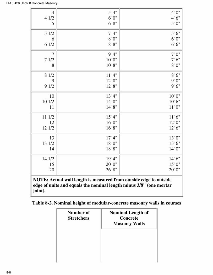
Keep all horizontal dimensions in multiples of nominal full-length masonry units. Both
horizontal and vertical dimensions should be designed in multiples of 8 inches. Table
8-1 below gives the nominal lengths of modular-concrete masonry walls in the number
●
FM 5-428 Chptr 8 Concrete Masonry
8-6

of stretchers, and Table 8-2 below gives the nominal heights of modular-concrete
masonry walls in the number of courses.
Plan the horizontal dimensions in multiples of 8 inches (half-length units) and the
vertical dimensions in multiples of 4 inches, when using 8 by 4 by 16 blocks. If the
wall thickness is either greater or less than the length of one half-length unit, use a
special length unit at each corner in each course.
●
Figure 8-3. Planning concrete masonry wall openings
Table 8-1. Nominal length of modular-concrete masonry walls in stretchers
Number
of
Stretchers
Nominal Length of Concrete Masonry Walls
Units 15 5/8" Long and
Half Units 7 5/8" Long
With 3/8" Thick Head
Joints
Units 11 5/8" Long and
Half Units 5 5/8" Long
With 3/8" Thick Head
Joints
1
1 1/2
2
1' 4"
2' 0"
2' 8"
1' 0"
1' 6"
2' 0"
2 1/2
3
3 1/2
3' 4"
4' 0"
4' 8"
2' 6"
3' 0"
3' 6"
FM 5-428 Chptr 8 Concrete Masonry
8-7
4
4 1/2
5
5' 4"
6' 0"
6' 8"
4' 0"
4' 6"
5' 0"
5 1/2
6
6 1/2
7' 4"
8' 0"
8' 8"
5' 6"
6' 0"
6' 6"
7
7 1/2
8
9' 4"
10' 0"
10' 8"
7' 0"
7' 6"
8' 0"
8 1/2
9
9 1/2
11' 4"
12' 0"
12' 8"
8' 6"
9' 0"
9' 6"
10
10 1/2
11
13' 4"
14' 0"
14' 8"
10' 0"
10' 6"
11' 0"
11 1/2
12
12 1/2
15' 4"
16' 0"
16' 8"
11' 6"
12' 0"
12' 6"
13
13 1/2
14
17' 4"
18' 0"
18' 8"
13' 0"
13' 6"
14' 0"
14 1/2
15
20
19' 4"
20' 0"
26' 8"
14' 6"
15' 0"
20' 0"
NOTE: Actual wall length is measured from outside edge to outside
edge of units and equals the nominal length minus 3/8" (one mortar
joint).
Table 8-2. Nominal height of modular-concrete masonry walls in courses
Number of
Stretchers
Nominal Length of
Concrete
Masonry Walls
FM 5-428 Chptr 8 Concrete Masonry
8-8

Units 7
5/8"
High and
3/8"
Thick Bed
Joints
Units 3
5/8"
High and
3/8"
Thick Bed
Joints
1
2
3
8"
1' 4"
2' 0"
4"
8"
1' 0"
4
5
6
2' 8"
3' 4"
4' 0"
1' 4"
1' 8"
2' 0"
7 4' 8" 2' 4"
8 5' 4" 2' 8"
9 6' 0" 3' 0"
10 6' 8" 3' 4"
15 10' 0" 5' 0"
20 13' 4" 6' 8"
25 16' 8" 8' 4"
30 20' 0" 10' 0"
35 23' 4" 11' 8"
40 26' 8" 13' 4"
45 30' 0" 15' 0"
50 33' 4" 16' 8"
NOTE: For concrete masonry units 7 5/8" and
3 5/8" in height laid with 3/8'' mortar joints.
Height is measured from center to center of
mortar joints.
FM 5-428 Chptr 8 Concrete Masonry
8-9

WALLS AND WALL FOOTINGS
8-14. Place masonry wall footings on firm, undisturbed soil having adequate load-bearing
capacity to carry the design load and below frost penetration. Unless local requirements or
codes specify otherwise, make the footings for small buildings twice as wide as the thickness
of the walls they support. Table 8-3 below gives both the unit weights and quantities for
modular-concrete masonry walls. Footing thickness equals wall width (see Figure 8-4 below).
Table 8-3. Unit weight and quantities for modular concrete masonry walls
Actual
Unit Size
(Width x
Height x
Length), in
Inches
Nominal
Wall
Thick-
ness, in
Inches
For 100 Sq Ft of Walls
Num-
ber of
Units
Average Weight of Finished Wall
Heavy-
weight
Aggregate,
in Lb*
Lightweight
Aggregate,
in Lb*
Mortar,*in Cu
Ft
3 5/8 x 3
5/8 x 15 5/8
5 5/8 x 3
5/8 x 15 5/8
7 5/8 x 3
5/8 x 15 5/8
4
6
8
225
225
225
3,050
4,550
5.700
2,150
3,050
3,700
9.5
9.5
9.5
6
6
6
3 5/8 x 7
5/8 x 15 5/8
5 5/8 x 7
5/8 x 15 5/8
7 5/8 x 7
5/8 x 15 5/8
11 5/8 x
7/5/8 x 15
5/8
4
6
8
12
112.5
112.5
112.5
112.5
2,850
4,350
5,500
7,950
2,050
2,950
3,600
4,900
6.0
6.0
6.0
6.0
7
7
7
7
NOTES: 1. Table is based on 3/8-inch mortar joints.
2. Actual weight of 100 sq ft of wall can be computed by formula W (n) + 150(M).
where--
W = actual weight of a single unit.
n = number of units for 100 sq ft of wall.
M = cu ft of mortar for 100 sq ft of wall.
*Actual weight within + 7% of average weight. With face-shell mortar bedding. Mortar
quantities should include 10% allowance for waste.
FM 5-428 Chptr 8 Concrete Masonry
8-10

Figure 8-4. Dimensions of masonry wall footings
SUBSURFACE DRAINAGE
8-15. If you expect the groundwater level during a wet season to reach the basement floor
elevation, place a line of drain tile along the exterior side of the footings. The tile line should
fall at least 1/2 inch in 12 feet and drain to a suitable outlet. Place pieces of roofing felt over
the joints to keep out sediment during backfilling. Cover the tile line to a depth of 12 inches
with a permeable fill of coarse gravel or crushed stone ranging from 1 to 1 1/2 inches in size.
When the first floor is in place, fill the balance of the trench with earth from the excavation.
BASEMENT WALLS
8-16. Always give exterior concrete masonry basement walls two 1/4-inch thick coats of
parging, using either portland cement mortar (1:2 1/2 mix by volume) or joint mortar.
Step 1. In hot, dry weather dampen the wall surface very lightly with a fog water spray before
applying the first parging coat.
Step 2. Roughen the first coat when it is partly hardens, to provide a bond for the second
parging coat.
Step 3. Wait for the first coat to harden for 24 hours, then dampen it lightly just before
applying the second coat. Keep the second coat damp for at least 48 hours following
application.
Step 4. For below-grade parged surfaces in very wet soils, use two continuous coatings of
bituminous mastic brushed over a suitable priming coat. Make sure that the parging is dry
before you apply the primer and that the primer is dry when you apply the bituminous mastic.
Do not backfill against concrete masonry walls until the first floor is in place.
FM 5-428 Chptr 8 Concrete Masonry
8-11

FLOOR AND ROOF SUPPORT
8-17. Use solid masonry courses to support floor beams or floor slabs to help distribute the
loads over the walls as well as provide a termite barrier. Use either solid masonry units or fill
the cores of hollow block with concrete or mortar. If using blocks that are filled with mortar,
lay strips of expanded metal lath in the bed joint underneath to support the fill.
WEATHERTIGHT CONCRETE MASONRY WALLS
8-18. Good workmanship is a very important factor in building weathertight walls.
Step 1. Lay each masonry unit plumb and true.
Step 2. Fill both horizontal and vertical joints completely; compact them by tooling when the
mortar partly stiffens.
Step 3. Add flashing at vertical joints in copings and caps, at the joints between the roofs and
walls, and below cornices and other members that project beyond the wall face.
Step 4. Shed water away from the wall surface by providing drips for chimney caps, sills, and
other projecting ledges. Make sure that drains and gutters are large enough so that
overflowing water does not run down masonry surfaces.
FIRST COURSE
8-19. The first step in building a concrete masonry wall is to locate the corners of the
structure. Then check the layout by placing the first course blocks without mortar (see Figure
8-5).
FM 5-428 Chptr 8 Concrete Masonry
8-12
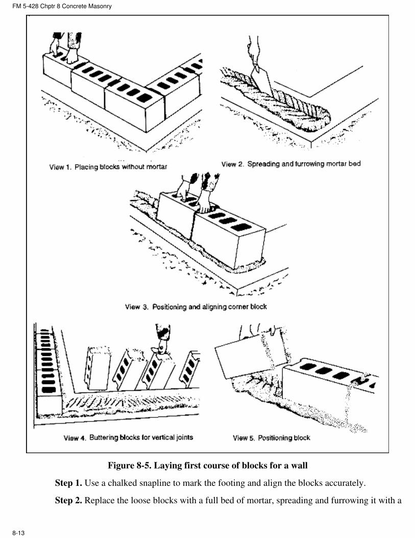
Figure 8-5. Laying first course of blocks for a wall
Step 1. Use a chalked snapline to mark the footing and align the blocks accurately.
Step 2. Replace the loose blocks with a full bed of mortar, spreading and furrowing it with a
FM 5-428 Chptr 8 Concrete Masonry
8-13

trowel to ensure plenty of mortar under the bottom edges of the first course.
Step 3. Use care to position and align the corner block first.
Step 4. Lay the remaining first course blocks with the thicker end up to provide a larger
mortar-bedding area.
Step 5. Apply mortar to the block ends for the vertical joints by placing several blocks on end
and buttering them all in one operation. Make the joints 3/8 inch thick.
Step 6. Place each block in its final position and push it down vertically into the mortar bed
and against the previously laid block to obtain a well-filled vertical mortar joint.
Step 7. Use a mason's level after laying three or four blocks as a straightedge to check correct
block alignment (see Figure 8-6).
Figure 8-6. Leveling and plumbing first course of blocks for a wall
Step 8. Use the level to bring the blocks to proper grade and make them plumb by tapping
with a trowel handle as shown in Figure 8-6.
FM 5-428 Chptr 8 Concrete Masonry
8-14

Step 9. Lay out the first course of concrete masonry very carefully, making sure that it is
properly aligned, level, and plumb. This ensures that succeeding courses and the final wall are
both straight and true.
LAYING UP THE CORNERS
8-20. After laying the first course, build up the corners of the wall next, usually four or five
courses high.
Step 1. Move back each course one-half block.
Step 2. Apply mortar only to the tops of the blocks of the horizontal joints already laid.
Step 3. Apply mortar to the vertical joints either to the ends of the new block or the end of the
block previously laid, or both, to ensure well-filled joints (see Figure 8-7).
Figure 8-7. Vertical joints
Step 4. Lay each course at the corner, check it with a level for alignment for leveling and for
ensuring that it is plumb (see Figure 8-8).
FM 5-428 Chptr 8 Concrete Masonry
8-15

Figure 8-8. Checking each course at the corner
Step 5. Use care to check each block with a level or straightedge to make sure that all the
FM 5-428 Chptr 8 Concrete Masonry
8-16

block faces are in the same plane to ensure true, straight walls. A story or course pole, which
is a board with markings 8 inch apart as shown in Figure 8-9 helps to accurately determine
the top of each masonry course.
Figure 8-9. Using a story or course pole
Step 6. Check the horizontal block spacing by placing a level diagonally across the corners of
the blocks as shown in Figure 8-10.
FM 5-428 Chptr 8 Concrete Masonry
8-17

Figure 8-10. Checking horizontal block spacing
LAYING BLOCKS BETWEEN CORNERS
8-21. When filling in the wall between the corners, follow the procedures below.
Step 1. Stretch a mason's line along the exterior block edges from corner to corner for each
course.
Step 2. Lay the top outside edge of each new block to this line (see Figure 8-11 below). How
you grip a block before laying it is important.
First, tip it slightly toward you so that you can see the edge of the course below.●
Place the lower edge of the new block directly on the edges of the blocks comprising
the course below, as shown in Figure 8-11.
●
Next, make all final position adjustments while the mortar is soft and plastic, because
any adjustments you make after the mortar stiffens will break the mortar bond and
allow water to penetrate.
●
Finally, level each block and align it to the mason's line by tapping it lightly with a
trowel handle.
●
Figure 8-11. Filling in the wall between corners
CLOSURE BLOCK
8-22. Before installing the closure block, butter both edges of the opening and all four vertical
edges of the closure block with mortar. Then lower the closure block carefully into place as
shown in Figure 8-12. If any mortar falls out leaving an open joint, remove the block and
repeat the procedure.
FM 5-428 Chptr 8 Concrete Masonry
8-18

Figure 8-12. Installing a closure block
MORTAR JOINTS
8-23. To ensure a good bond, do not spread mortar too far ahead of actually laying blocks or
it will stiffen and lose its plasticity. The recommended width of mortar joints for concrete
masonry units is approximately 3/8 inch thick which--when properly made--helps to produce
a weathertight, neat, and durable concrete masonry wall. As you lay each block, cut off
excess mortar extruding from the joints using a trowel (see Figure 8-13) and throw it back on
the mortar board to rework into the fresh mortar. Do not, however, rework any dead mortar
from the scaffold or floor.
Figure 8-13. Cutting off excess mortar from the joints
TOOLING
8-24. Weathertight joints and the neat appearance of concrete masonry walls depend on
proper tooling. After laying a section of the wall, tool the mortar joints when the mortar
becomes thumbprint hard. Tooling compacts the mortar and forces it tightly against the
FM 5-428 Chptr 8 Concrete Masonry
8-19

masonry on each side of the joint. Use either concave or V-shaped tooling on all joints (see
Figure 8-14). Tool vertical joints first, followed by striking the horizontal joints with a long
jointer (see Figure 8-15 below). Trim off mortar burrs from the tooling flush with the wall
face using a trowel or soft bristle brush, or by rubbing with a burlap bag.
Figure 8-14. Tooling mortar joints for weathertight exterior walls
FM 5-428 Chptr 8 Concrete Masonry
8-20

Figure 8-15. Tooling mortar joints
ANCHOR BOLTS
8-25. You must prepare in advance for installing wood plates on top of hollow concrete
FM 5-428 Chptr 8 Concrete Masonry
8-21

FM 5-428 Chptr 8 Concrete Masonry
8-22
masonry walls with anchor bolts. To do this, place pieces of metal lath in the
second horizontal mortar joint from the top of the wall under the cores that
will contain the bolts. Use anchor bolts 1/2 inch in diameter and 18 inches
long, spacing them up to a maximum of 4 feet apart. When you complete the
top course, insert the bolts into the cores of the top two courses, and fill the
cores with concrete or mortar. The metal lath underneath holds the concrete
or mortar filling in place. The threaded end of the bolt should extend above
the top of the wall as shown in Figure 8-16.
CONTROL JOINTS
8-26. Control joints are continuous vertical joints that permit the masonry
wall to move slightly under unusual stresses without cracking. A
combination of full-and half-length blocks form the continuous vertical joint
as shown in view 1 of Figure 8-17. Lay up control joints in mortar just as
any other joint, but if they are exposed to either the weather or to view,
caulk them as well. After the mortar is quite stiff, rake it out to a depth of
about 3/4 inch to make a recess for the caulking compound as shown in view
2 of Figure 8-17.

FM 5-428 Chptr 8 Concrete Masonry
8-23
Figure 8-16. Installing anchor bolts for wood plates

Figure 8-17. Making a control joint
Use a thin, flat caulking trowel to force the compound into the joint. You can make a second
type of control joint by inserting building paper or roofing felt into the block end cores
FM 5-428 Chptr 8 Concrete Masonry
8-24

FM 5-428 Chptr 8 Concrete Masonry
8-25
extending the full height of the joint (see Figure 8-18). Cut the paper or felt
to convenient lengths, but wide enough to extend across the joint. The paper
or felt material prevents the mortar from bonding on that side of the joint.
Use control joint blocks, if available (see Figure 8-18).
INTERSECTING WALLS
8-27. The two types of intersecting walls are bearing and nonbearing.
BEARING WALLS
8-28. Do not join intersecting concrete block-bearing walls with a masonry
bond, except at the corners. Instead, terminate one wall at the face of the
second wall with a control joint. Tie the intersecting walls together with Z-
shaped metal-tie bars 1/4 by 1 1/4 by 28 inches in size, having a 2-inch right
angle bend on each end (see Figure 8-19). Space the tie bars no more
than 4 feet apart vertically, and place pieces of metal lath under the block
cores that will contain the tie-bar ends (see Figure 8-16). Embed the right
angle bends in the cores by filling them with mortar or concrete (see Figure
8-19)

FM 5-428 Chptr 8 Concrete Masonry
8-26
Figure 8-18. Control joints made using roofing felt or control joint blocksVertical
joints

Figure 8-19. Tying intersecting bearing walls
NONBEARING WALLS
8-29. To join intersecting nonbearing block walls, terminate one wall at the face of the second
with a control joint. Place strips of metal lath or 1/4-inch mesh galvanized hardware cloth
across the joint between the two walls in alternate courses. Insert one half of the metal strips
into one wall as you build it; tie the other halves into mortar joints as you lay the second wall
FM 5-428 Chptr 8 Concrete Masonry
8-27

FM 5-428 Chptr 8 Concrete Masonry
8-28
Figure 8-20. Tying intersecting nonbearing walls

FM 5-428 Chptr 8 Concrete Masonry
8-29
LINTELS
8-30. Modular door and window openings usually require lintels to support
the blocks over the openings. Use precast concrete lintels that contain an
offset on the underside to fit the modular openings or use steel-lintel angles
that you install with an offset on the underside (see Figure 8-21) to fit
modular openings. In either case, place a noncorroding metal plate
under the lintel ends at the control joints to allow the lintel to slip and the
control joints to function properly. Apply a full bed of mortar over the metal
plate to uniformly distribute the lintel load.
SILLS
8-31. Install precast concrete sills following wall construction (see Figure 8-
22). Fill the joints tightly at the ends of the sills with mortar or a caulking
compound.

FM 5-428 Chptr 8 Concrete Masonry
8-30
Figure 8-21. Installing precast concrete lintels without and with steel angles

Figure 8-22. Installing precast concrete sills
PATCHING AND CLEANING BLOCK WALLS
8-32. When laying concrete masonry walls, be very careful not to smear mortar into the block
surfaces, because you cannot remove hardened, embedded mortar smears, even with an acid
wash; also paint will not cover them. Allow any droppings to dry and harden. You can then
chip off most of the mortar with a small piece of broken concrete block (see Figure 8-23), or
with a trowel. A final brushing of the spot will remove practically all of the mortar. Always
patch mortar joints and fill holes made by nails or line pins with fresh mortar.
FM 5-428 Chptr 8 Concrete Masonry
8-31

FM 5-428 Chptr 8 Concrete Masonry
8-32
Figure 8-23. Cleaning mortar droppings from concrete block wall

8-33. The mason is responsible for laying out the job to do the work properly. Masons must
make sure that the walls are plumb and that courses are level. They are also responsible for
the quality of all the detail work such as cutting and fitting masonry units, making joints, and
installing anchor bolts and ties in intersecting walls.
8-34. The mason's helper mixes mortar, keeps it tempered, and supplies concrete blocks and
mortar to the mason as needed. Helpers aid the mason in laying out the job and sometimes lay
out blocks ahead on an adjacent course to expedite the mason's work.
SECTION III. RUBBLE
RUBBLE STONE MASONRY
8-35. You can use rubble stone masonry (see Figure 8-24 below) for walls--both above and
below ground--and for bridge abutments, particularly when form lumber or masonry units are
not available. You can lay up rubble masonry with or without mortar, but for strength and
stability use mortar. There are two types of rubble-stone masonry: random and coursed.
Figure 8-24. Rubble stone masonry
RANDON STONE MASONRY
8-36. This type is the crudest of all types of stonework. It does not require laying the stone in
courses (see Figure 8-24 above), but each layer must contain bonding stones that extend
through the wall (as shown in Figure 8-25) to tie the walls together. Make the bed joints
horizontal for stability; the build or head joints can run in any direction.
FM 5-428 Chptr 8 Concrete Masonry
8-33

Figure 8-25. Bonding stones extend through a rubble stone masonry wall
COURSED RUBBLE MASONRY
8-37. This type contains roughly squared stones laid in nearly continuous horizontal bed
joints as shown in Figure 8-24.
RANDOM RUBBLE MASONRY MATERIALS
8-38. The two main random rubble masonry materials are stones and mortar. Some of the
more common suitable stones are limestone, sandstone, granite, and slate.
STONES
8-39. Use stones that are strong, durable, and cheap for random rubble masonry. Durability
and strength depend on the stone's chemical composition and physical structure. Use
unsquared stones or fieldstones from nearby ledges or quarries. No stones should be larger
than what two persons can handle easily. The larger the variety of sizes you select, the less
mortar you need.
MORTAR
8-40. Table 7-1 gives the proportions of the portland-cement-lime mortar mixture to use with
random rubble masonry. Mortar made with ordinary portland cement stains most types of
stone. To prevent staining, substitute nonstaining white portland cement. Lime usually does
not stain the stone.
LAYING RUBBLE STONE MASONRY
8-41. The quality of workmanship affects the economy, durability, and strength of a rubble
stone masonry wall more than any other factor. Lay out the wall--
By eye. If the wall does not have to be exactly plumb and true to line, lay it out by eye●
FM 5-428 Chptr 8 Concrete Masonry
8-34

without using a level and line. This requires frequent sighting.
By line. If the wall must be exactly plumb and true to line, erect wood corner posts to
serve as corner leads, and lay the stone with a line. Remember that some parts of the
stone will extend farther away from the line than other parts. Do not try to lay the stone
in level courses.
●
RULES FOR LAYING
8-42. Lay each stone on its broadest face. If appearance is important, place the larger stones
in the lower courses. Lay stones of increasingly smaller sizes as you build to the top of the
wall.
Moistening. Moisten porous stones before placing them in mortar to prevent water
absorption from the mortar, thereby weakening the bond.
●
Packing and filling. Pack adjoining stones as tightly as practicable, completely filling
any spaces between them with smaller stones and mortar.
●
Removing. If removing a stone after placing it on the mortar bed, lift it clear and reset
it.
●
FOOTINGS
8-43. Because a footing is always larger than the wall itself, use the largest stones in the
footing to give it greater strength and lessen the risk of unequal settlement. Select footing
stones as long as the footing is wide, if possible. Lay them in a mortar bed about 2 inches
deep, and fill all the spaces between them with smaller stones and mortar.
BED JOINTS
8-44. Bed-joint thickness varies with the stone you use. Spread enough mortar on top of the
lower course stone to completely fill the space between it and the stone you are placing. Take
care not to spread mortar too far ahead of the stonelaying.
HEAD JOINTS OR BUILDS
8-45. Form the head joints before the bed joint mortar sets up. After laying three or four
stones, make the head joints by slushing the small spaces with mortar and filling the larger
spaces with both small stones and mortar.
BONDING STONES
8-46. Be sure to use one bonding stone for every 6 to 10 square feet of wall. Bonding stones
pass all the way through the wall as shown in Figure 8-25. Offset each head joint from
adjacent head joints above and below it as much as possible (see Figure 8-25) to bond the
wall together and make it stronger.
FM 5-428 Chptr 8 Concrete Masonry
8-35

Figure 8-25. Bonding stones extend through a rubble stone masonry wall
FM 5-428 Chptr 8 Concrete Masonry
8-36

Chapter 9
Brick and Tile Masonry
9-1. For at least 5000 years, bricks have been popular for their strength, durability, and beauty.
Although traditionally made of natural clay that is heated in a kiln at high temperatures, many
bricks today are made from compressed concrete and come in a wide variety of shapes and colors.
Bricks can be used for a variety of structures including house walls, garden walls, retaining walls,
chimneys and fireplaces, and also pavers for driveways, walkways, and patios.
SECTION I. CHARACTERISTICS OF BRICK
PHYSICAL PROPERTIES AND CLASSIFICATION
9-2. Structural clay products includes brick, hollow tile of all types, and architectural terra cotta,
but exclude thin wall tile, sewer pipe, flue linings, and drain tile.
BRICK MASONRY UNITS
9-3. Bricks are small masonry units that are either solid or cored but not more than 25 percent.
They are kiln-fired (baked) from various clay and shale mixtures. The chemical and physical
characteristics of the ingredients change considerably and combine with the kiln temperature to
produce the brick in a variety of colors and hardnesses. The clay or shale pits in some regions
yield a product that is simply ground, moistened, formed, and baked into durable brick. In other
regions, the clay or shale from several pits must be mixed to produce durable brick. Bricks are
small enough to place with one hand. Uniform units can be laid in courses with mortar joints to
form walls of almost unlimited length and height.
BRICK SIZES AND WEIGHT
9-4. Standard United States (US) bricks are 2 1/4 by 3 3/4 by 8 inches actual size. They may have
three core holes or ten core holes. Modular US bricks are (2 2/3 by 4 by 8 inches) nominal size,
normally having three core holes. English bricks are 3 by 4 1/2 by 9 inches, Roman bricks are 1
1/2 by 4 by 12 inches, and Norman bricks are 2 3/4 by 4 by 12 inches nominal size. Actual brick
dimensions are smaller, usually by an amount equal to mortar joint width. Brick weighs from 100
to 150 pounds per cubic foot, depending on its ingredients and firing duration. Well-burned brick
is heavier than underburned brick.
CUT SHAPES
9-5. Sometimes you must cut a brick into various shapes to fill in spaces at corners and other
locations where a full brick does not fit. Figure 9-1 shows the more common cut shapes: half or
FM 5-428 Chptr 9 Brick and Tile Masonry
9-1

bat, three-quarter closure, quarter closure, king closure, queen closure, and split.
Figure 9-1. Common cut brick shapes
SURFACE NAMES
9-6. The five surfaces of a brick are called face, side, cull, end, and beds as shown in Figure 9-2.
Figure 9-2. Names of brick surfaces
BRICK CLASSIFICATION
9-7. The three general types of structural brick-masonry units are solid, hollow, and architectural
terra cotta. All three can serve a structural function, a decorative function, or a combination of
both. The three types differ in their formation and composition, and are specific in their use.
Bricks commonly used in construction are--
Building bricks. Also called common, hard, or kiln-run bricks, these bricks are made from
ordinary clays or shales and fired in kilns. They have no special scoring, markings, surface
texture, or color. Building bricks are generally used as the backing courses in either solid or
cavity brick walls because the harder and more durable kinds are preferred.
●
Face bricks. These are better quality and have better durability and appearance than●
FM 5-428 Chptr 9 Brick and Tile Masonry
9-2

building bricks because they are used in exposed wall faces. The most common face brick
colors are various shades of brown, red, gray, yellow, and white.
Clinker bricks. These bricks are oven-burnt in the kiln. They are usually rough, hard,
durable, and sometimes irregular in shape.
●
Pressed bricks. These bricks are made by the dry-press process rather than by kiln-firing.
They have regular smooth faces, sharp edges, and perfectly square corners. Ordinarily, they
are used as face bricks.
●
Glazed bricks. These have one surface coated with a white or other color of ceramic
glazing. The glazing forms when mineral ingredients fuse together in a glass-like coating
during burning. Glazed brick is particularly suited to walls or partitions in hospitals, dairies,
laboratories, and other structures requiring sanitary conditions and easy cleaning.
●
Fire bricks. These are made from a special type of fire clay to withstand the high
temperatures of fireplaces, boilers, and similar constructions without cracking or
decomposing. Fire brick is generally larger than other structural brick, and often is
hand-molded.
●
Cored bricks. These bricks have ten holes (two rows of five holes each) extending through
their beds to reduce weight. Walls built from all cored bricks are not much different in
strength than walls built from all solid bricks, and both have about the same resistance to
moisture penetration. Whether cored or solid, use the more easily available brick that meets
building requirements.
●
European bricks. Their strength and durability (particularly English and Dutch bricks) are
about the same as US clay bricks.
●
Sand-lime bricks. These bricks are made from a lean mixture of slaked lime and fine sand
containing a lot of silica. They are molded under mechanical pressure and hardened under
steam pressure. These are used extensively in Germany.
●
STRENGTH OF BRICK MASONRY
9-8. The strength of a single brick masonry unit varies widely, depending on its ingredients and
manufacturing method. The main factors governing the strength of brick masonry are--
Brick strength.●
Mortar strength and elasticity.●
Bricklayer workmanship.●
Brick uniformity.●
Bricklaying method used.●
RANGES
9-9. Bricks can have an ultimate compressive strength as low as 1,600 psi, whereas some
well-burned bricks have compressive strengths exceeding 15,000 psi.
PORTLAND-CEMENT-LIME MORTAR
9-10. Brick masonry laid with portland-cement-line mortar is stronger than an individual brick
unit because this mortar is normally stronger than the brick. The load-carrying capacity of a wall
or column made with plain lime mortar is much less than half that made with
FM 5-428 Chptr 9 Brick and Tile Masonry
9-3

portland-cement-lime mortar. The compressive working strength of a brick wall or column laid
with cement-lime mortar normally ranges from 500 to 600 psi.
DRY BRICK
9-11. In order for mortar to bond to brick, sufficient water must be present to completely hydrate
the portland cement in the mortar. Bricks sometimes have high absorption and, if not corrected,
will suck the water out of the mortar preventing complete hydration. A field test to determine if
the brick has absorptive qualities is as follows: Using a medicine dropper, place 20 drops of water
in a 1-inch circle (about the size of a quarter). If the brick absorbs all the water in less than 1 1/2
minutes, then it will suck the water out of the mortar when laid. To correct this condition,
thoroughly wet the bricks and allow time for the surfaces to air-dry before placing.
WEATHER RESISTANCE
9-12. A brick's resistance to weathering depends almost entirely upon its resistance to water
penetration, because freeze-thaw action is almost the only type of weathering that affects it.
9-13. A brick wall made with superior workmanship will resist rain water penetration during a
storm lasting as long as 24 hours accompanied by a 50 to 60 mile per hour wind.
9-14. Two important factors in preventing water penetration are tooled-mortar joints and caulking
around windows and door frames. Mortar joints that bond tightly to the brick resist moisture
penetration better than joints with loose bonds. Slushing or grouting the joints after laying the
brick does not fill the joint completely. Fill the joints between the brick solidly, especially in the
face tier. Tool the joint to a concave surface before the mortar sets up. When tooling, use enough
force to press the mortar tightly against the brick on both sides of the joint. Although good
bricklaying workmanship does not permit water penetration, it provides some means of removing
moisture that does penetrate the masonry, such as properly designed flashing or the use of cavity
walls.
FIRE RESISTANCE
9-15. Table 9-1 gives the hours of fire resistance for various thicknesses of brick walls determined
by tests conducted on brick walls laid with portlandcement-lime mortar. The ASTM standard
method for conducting fire tests was used.
Table 9-1. Fire resistance of brick load-bearing walls laid with portland-cement-lime mortar
Normal Wall
Thickness, in
Inches
Types of Wall Material Ultimate Fire-Resistance Period. Incombustible
Members Framed into Wall or not Framed in
Members
No Plaster, in
Hours
Plaster on
One Side, in
Hours
Plaster on
Two SIdes, in
Hours
4 Solid Clay or shale 1 1/4 1 3/4 2 1/2
8 Solid Clay or shale 5 6 7
FM 5-428 Chptr 9 Brick and Tile Masonry
9-4

12 Solid Clay or shale 10 10 12
8 Hollow rowlock Clay or shale 2 1/2 3 4
12 Hollow rowlock Clay or shale 5 6 7
9 to 10 Cavity Clay or shale 5 6 7
4 Solid Sand lime 1 3/4 2 1/2 3
8 Solid Sand lime 7 8 9
12 Solid Sand lime 10 10 12
NOTE: Not less than 1/2 inch of 1-3 sanded gypsum plaster is required to develop these rating.
ABRASION RESISTANCE
9-16. A brick's resistance to abrasion depends largely upon its compressive strength, which is
determined by how well it was fired. Well-burned brick has excellent wearing qualities.
INSULATING QUALITIES OF BRICK MASONRY
9-17. A brick masonry wall expands and contracts with temperature change. However, because
the wall itself takes up a lot of the expansion and contraction, the amount of movement calculated
theoretically does not actually occur. Therefore, walls up to 200 feet long do not need expansion
joints, but longer walls require one expansion joint for every 200 feet.
HEAT
9-18. Solid-brick masonry walls provide very little insulation from heat and cold. A cavity wall or
a brick wall backed with hollow clay tile gives much better insulating value.
SOUND
9-19. Brick walls are massive and provide good sound insulation. Generally, the heavier the wall,
the better its sound-insulating value. However, the sound insulation provided by a wall more than
12 inches thick is not much greater than a wall 10 to 12 inches thick. Dividing a wall into two or
more layers, such as a cavity wall, increases its resistance to sound transmission from one side of
the wall to the other. Brick walls poorly absorb sound originating within the walls and reflect
much of the sound back into the structure. However, impact sounds, such as a hammer striking the
wall, travel a long way along the wall.
SECTION II. BRICKLAYING METHODS
FM 5-428 Chptr 9 Brick and Tile Masonry
9-5

FUNDAMENTALS
9-20. Good bricklaying procedures depend on good workmanship and efficiency. Efficiency
means to do the work with the fewest possible motions. Each motion should have a purpose and
accomplish a particular result. After learning the fundamentals, study your own work to eliminate
unnecessary motions, thereby achieving maximum efficiency. Organize your work to ensure a
continual supply of brick and mortar. Plan the scaffolding before the work begins, and build it so
that it interferes as little as possible with other workers. Paragraphs 7-3 and 7-4 describe mason's
tools and equipment, which are generally the same as, or similar to, those used in bricklaying.
BRICK MASONRY TERMS
9-21. You need to know the specific terms that describe the position of masonry units and mortar
joints in a wall (see Figure 9-3). These terms include--
Course. One of several continuous, horizontal layers (or rows) of masonry units bonded
together.
●
Wythe. Each continuous, vertical section of a wall, one masonry unit thick, such as the
thickness of masonry separating flues in a chimney. Sometimes called a tier.
●
Stretcher. A masonry unit laid flat on its bed along the length of a wall with its face parallel
to the face of the wall.
●
Header. A masonry unit laid flat on its bed across the width of a wall with its face
perpendicular to the face of the wall. Generally used to bond two wythes.
●
Rowlock. A header laid on its face or edge across the width of a wall.●
Bull stretcher. A rowlock brick laid with its bed parallel to the face of the wall.●
Bull header. A rowlock brick laid with its bed perpendicular to the face of the wall.●
Soldier. A brick laid on its end with its face perpendicular to the face of the wall.●
FM 5-428 Chptr 9 Brick and Tile Masonry
9-6

Figure 9-3. Masonry units and mortar joints
TYPES OF BONDS
9-22. The term bond as used in masonry has three different meanings: structural bond, mortar
bond, or pattern bond. Metal ties are also used as bonds.
Structural bond. This means how the individual masonry units interlock or tie together into
a single structural unit. You can achieve structural bonding of brick and tile walls in one of
three ways:
- Overlapping (interlocking) the masonry units.
- Embedding metal ties in connecting joints.
- Using grout to adhere adjacent wythes of masonry.
●
Mortar bond. This is adhesion of the mortar joint to the masonry units or to the reinforcing
steel.
●
FM 5-428 Chptr 9 Brick and Tile Masonry
9-7

Pattern Bond. This is pattern formed by the masonry units and mortar joints on the face of a
wall. The pattern may result from the structural bond or may be purely decorative and
unrelated to the structural bond. Figure 9-4 shows the six basic bond patterns in common
use today: running bond, common or American bond, Flemish bond, English bond, stack
bond, and English cross or Dutch bond.
-Running bond. This is the simplest of the six bonds, consisting of all stretchers. The bond
has no headers, therefore metal ties usually form the structural bond. The running bond is
used largely in cavity wall construction, brick veneer walls, and facing tile walls made with
extra wide stretcher tile.
- Common or American bond. This is variation of the running bond having a course of
full-length headers at regular intervals that provide the structural bond as well as patterns.
Header courses usually appear at every fifth, sixth, or seventh course, depending on the
structural bonding requirements or the common bond that will vary with a Flemish header
course. In laying out any bond pattern, be sure to start the corners correctly. In a common
bond, use a three-quarter closure at the corner of each header course.
- Flemish bond. Each course consists of alternating headers and stretchers. The headers in
every other course center over and under the stretchers in the courses in between. The joints
between stretchers in all stretcher courses align vertically. When headers are not required
for structural bonding, use bricks called blind headers. Start the corners two different ways;
in the Dutch corner, a three-quarter closure starts each course, and with the English corner,
a 2-inch or quarter closure starts the course.
- English bond. This pattern consists of alternating courses of headers and stretchers. The
headers center over and under the stretchers. The joints between stretchers in all stretcher
courses do not align vertically. Use blind headers in courses that are not structural bonding
courses.
- Stack bond. This is purely a pattern bond, with no overlapping units and all vertical joints
aligning. You must use dimensional-accurate or prematched units to achieve good vertical
joint alignment. You can vary the pattern with combinations and modifications of the basic
patterns shown in Figure 9-4. This pattern usually bonds to the backing with rigid steel ties,
or 8-inch-thick stretcher units when available. In large wall areas or for load-bearing
construction, insert steel-pencil rods into the horizontal mortar joints as reinforcement.
- English cross or Dutch bond. A variation of the English bond, the English cross or Dutch
bond differs only in that the joints between the stretchers in the stretcher courses align
vertically. These joints center on the headers in the courses above and below.
●
Metal ties. When a wall bond has no header courses, use metal ties to bond the exterior wall
brick to the backing courses. Figure 9-5 shows three typical metal ties.
●
FM 5-428 Chptr 9 Brick and Tile Masonry
9-8

Figure 9-4. Types of masonry bond
Figure 9-5. Metal ties
FLASHING
9-23. Install flashing at any spot where moisture is likely to enter a brick masonry structure.
Flashing diverts the moisture back outside. Always install flashing under horizontal masonry
surfaces such as sills and copings and at intersections between masonry walls and horizontal
surfaces. This also includes roof and parapet or a roof and chimney, above openings such as doors
and windows, and frequently at floor lines, depending on the type of construction. The flashing
should extend through the exterior wall face and then turn downward against the wall face to form
a drop. Provide weep holes at intervals of 18 to 24 inches to drain water that accumulates on the
flashing to the outside. Weep holes are even more important when appearance requires the
flashing to stop behind the wall face instead of extending through the wall. This type of concealed
flashing with tooled mortar joints often retains water in the wall for long periods and, by
concentrating the moisture at one spot it does more harm than good.
FM 5-428 Chptr 9 Brick and Tile Masonry
9-9

MAKING AND POINTING MORTAR JOINTS
9-24. Pointing is filling exposed joints with mortar immediately after laying a wall. You can also
fill holes and correct defective mortar joints by pointing, using a pointing trowel.
MORTAR JOINT
9-25. There is no rule governing the thickness of a brick masonry mortar joint. Irregularly shaped
bricks may require mortar joints up to 1/2 inch thick to compensate for the irregularities.
However, mortar joints 1/4 inch thick are the strongest. Use this thickness whenever the bricks are
regular enough in shape to permit it.
9-26. A slush joint is made simply by depositing the mortar on top of the head joints allowing it to
run down between the bricks to form a joint. You cannot make solid joints this way. Even if you
fill the space between the bricks completely, there is no way you can compact the mortar against
the brick faces, and a poor bond will result.
PICKING UP AND SPREADING MORTAR
9-27. Figure 9-6 shows the correct way to hold a trowel firmly in the grip with your thumb resting
on top of the handle, not encircling it. If you are right-handed, pick up mortar from the outside of
the mortar-board pile with the left edge of your trowel (see Figure 9-7 below). You can pick up
enough mortar to spread one to five bricks depending on the wall space and your skills. A pickup
for one brick forms only a small pile along the left edge of the trowel, however, a pickup for five
bricks is a full load for a large trowel as shown in view 2 of Figure 9-7.
Figure 9-6. Correct way to hold a trowel
FM 5-428 Chptr 9 Brick and Tile Masonry
9-10

Figure 9-7. Picking up and spreading mortar
9-28. If you are righthanded, spreading the mortar working from left to right along the wall.
Holding the left edge of the trowel directly over the centerline of the previous course, tilt the
trowel slightly and move it to the right (see view 3 Figure 9-7) dropping an equal amount of
mortar on each brick until the course is completed or the trowel is empty. Return any leftover
mortar to the trowel mortarboard.
MAKING BED AND HEAD JOINT
9-29. Do not spread the mortar for a bed joint too far ahead of laying (the length of 4 or 5 bricks is
best). Mortar spread out too far ahead dries out before the bricks bedded in it and causes a poor
bond as shown in Figure 9-8. The mortar must be soft and plastic so that the brick beds in it easily.
Spread the mortar about 1 inch thick, and then make a shallow furrow in it (see Figure 9-9 below).
A furrow that is too deep leaves a gap between the mortar and the bedded brick, which will reduce
the wall's resistance to water penetration.
FM 5-428 Chptr 9 Brick and Tile Masonry
9-11

Figure 9-8. A poorly bonded brick
Figure 9-9. Making a bed joint in a stretcher course
9-30. Cut off any mortar projecting beyond the wall line with the edge of the trowel (see Figure
9-9 above). Use a smooth, even stroke. Retain enough mortar on the trowel to butter the left end
of the first brick you will lay in the fresh mortar and throw the rest back on the mortar board.
9-31. Placing your thumb on one side of the brick and your fingers on the other, pick up the first
brick to be laid (see Figure 9-10). Apply as much mortar as will stick to the end of the brick and
then push it into place, squeezing out excess mortar at the head joint and at the sides as shown in
Figure 9-11 below. Make sure that the mortar completely fills the head joint. After bedding the
FM 5-428 Chptr 9 Brick and Tile Masonry
9-12
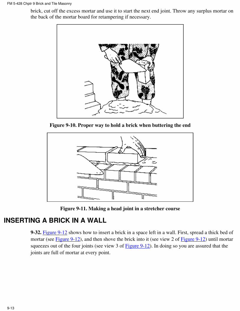
brick, cut off the excess mortar and use it to start the next end joint. Throw any surplus mortar on
the back of the mortar board for retampering if necessary.
Figure 9-10. Proper way to hold a brick when buttering the end
Figure 9-11. Making a head joint in a stretcher course
INSERTING A BRICK IN A WALL
9-32. Figure 9-12 shows how to insert a brick in a space left in a wall. First, spread a thick bed of
mortar (see Figure 9-12), and then shove the brick into it (see view 2 of Figure 9-12) until mortar
squeezes out of the four joints (see view 3 of Figure 9-12). In doing so you are assured that the
joints are full of mortar at every point.
FM 5-428 Chptr 9 Brick and Tile Masonry
9-13

Figure 9-12. Inserting a brick in a wall
MAKING CROSS JOINTS AND JOINTS CLOSURE
9-33. Spread the bed-joint mortar several brick widths in advance. Then spread mortar over the
face of the header brick before placing it in the wall (see view 1 of Figure 9-13). Next shove the
brick into place, squeezing out mortar at the top of the joint. Finally cut off the excess mortar as
shown in view 2 of Figure 9-13.
Figure 9-13. Making a cross joint in a header course
9-34. Figure 9-14 shows how to lay a closure brick in a header course. Spread about 1 inch of
FM 5-428 Chptr 9 Brick and Tile Masonry
9-14

mortar on the sides of the brick already in place (see view 1 of Figure 9-14), as well as on both
sides of the closure brick (see view 2 of Figure 9-14). Then lay the closure brick carefully into
position, without disturbing the brick already laid (see view 3 of Figure 9-14).
Figure 9-14. Making a closure joint in a header couse
9-35. To make a closure joint in stretcher courses, first spread plenty of mortar on the ends of the
brick already in place (see view 1 of Figure 9-15), as well as both ends of the closure brick (see
view 2 of Figure 9-15). Then carefully lay the closure brick without disturbing the brick already in
place (see view 3 of Figure 9-15). If you do disturb any adjacent bricks, you must remove and
relay them. Otherwise, cracks will form between the brick and mortar, allowing moisture to
penetrate the wall.
FM 5-428 Chptr 9 Brick and Tile Masonry
9-15

Figure 9-15. Making a closure joint in a stretcher course
CUTTING BRICK
9-36. Bricks will either be cut with a bolster or a brick set, using a brick hammer.
Using a bolster or brick set. When you must cut a brick to exact line, use a bolster (see
Figure 9-16) or brick set. The straight side of the tool's cutting edge should face both the
part of the brick to be saved, and the bricklayer. One mason's hammer blow should break
the brick. For an extremely hard brick, first cut it roughly using the brick hammer head, but
leave enough brick to cut accurately with the brick set.
●
Using a brick hammer. Use a brick hammer for normal cutting work, such as making the
closure bricks and bats around wall openings or completing corners. Hold the brick firmly
while cutting it. First cut a line around the brick using light blows. Hitting a sharp blow to
one side of the cutting line should split the brick at the cutting line (see view 1 of Figure
9-17). Trim rough spots using the hammer blade as shown in view 2 of Figure 9-17.
●
FM 5-428 Chptr 9 Brick and Tile Masonry
9-16

Figure 9-16. Cutting brick with a bolster
Figure 9-17. Cutting a brick with a hammer
FINISHING JOINTS.
9-37. Purpose. The exterior surfaces of mortar joints are finished to make brick masonry more
waterproof and give it a better appearance. If joints are simply cut flush with the brick and not
finished, shallow cracks develop immediately between the brick and the mortar. Finishing or
tooling the joint using the jointer shown in Figure 7-1 , Chapter 7, prevents such cracks. Always
finish a mortar joint before the mortar hardens too much. Figure 9-18 shows several types of joint
finishes, the more important of which are discussed below.
Concave joint. It is very weather tight. After removing the excess mortar with a trowel,
make this joint using a jointer that is slightly larger than the joint. Use force against the tool
to press the mortar tight against the brick on both sides of the mortar joint.
●
Flush joint. It is made by holding the trowel almost parallel to the face of the wall while
drawing its point along the joint.
●
Weather joint. It sheds water from a wall surface more easily. To make it, simply push
downward on the mortar with the top edge of the trowel.
●
FM 5-428 Chptr 9 Brick and Tile Masonry
9-17

Figure 9-18. Joint finishes
SECTION III. BRICK CONSTRUCTION
BRICKLAYER'S DUTIES
9-38. The bricklayer actually lays the brick and is responsible for laying out the job so that the
finished masonry has the proper quality and appearance. In wall construction, the bricklayer must
make sure that the walls are plumb and the courses are level.
BRICKTENDER'S DUTIES
9-39. The bricktender mixes mortar and carries brick, mortar, and supplies material to the
bricklayer, as needed. The bricktender fills the mortar board and places it in a convenient spot for
the bricklayer. He assists in layout and rapid backup bricklaying by laying out bricks in a line on
an adjacent course so that the bricklayer only has to move each brick a few inches to lay them. He
also wets brick during warm weather. There are four reasons why bricks must be wet just before
laying them:
A better bond is created between the brick and the mortar.●
Dust and dirt are washed from the brick surfaces because mortar adheres better to a clean
brick.
●
Mortar spreads more evenly under a wet brick surface.●
Dry brick absorbs water from the mortar rapidly, particularly portland-cement mortar. To
harden properly, cement requires sufficient moisture to complete the hydration process.
Therefore, if the brick absorbs too much water from the mortar, the cement will not harden
properly.
●
LAYING FOOTINGS
9-40. A qualified engineer must determine actual footing width and thickness for high walls and
walls that will carry a heavy load. A footing must rest below the frost line to prevent foundation
heaving and settlement.
WALL FOOTINGS
9-41. A wall requires a footing when the supporting soil cannot withstand the wall load without a
FM 5-428 Chptr 9 Brick and Tile Masonry
9-18

further means of load redistribution. The footing must be wider than the wall thickness as shown
in Figure 9-19. For an ordinary one- story building having an 8-inch-thick wall, a footing 16
inches wide and approximately 8 inches thick is usually large enough. Although brick masonry
footings are satisfactory, footings are normally made from concrete leveled on top to receive the
brick or stone foundation walls. After preparing the subgrade, place a mortar bed about 1 inch
thick on the subgrade to compensate for all irregularities. Lay the first course of the foundation on
the mortar bed followed by succeeding courses (see Figure 9-19).
Figure 9-19. Laying a wall footing
COLUMN FOOTINGS
9-42. Figure 9-20 shows a footing for a 12 by 16-inch brick column. This footing requires the
same construction method as the wall footing.
FM 5-428 Chptr 9 Brick and Tile Masonry
9-19

Figure 9-20. Column footing
LAYING AN 8-INCH COMMON-BOND BRICK WALL
9-43. You can build both solid and hollow walls from brick masonry. The solid 8- and 12-inch
walls in common bond are the most familiar ones in the US.
LAYING OUT THE WALL
9-44. To build a wall of a given length, adjust the width of the head joints so that a particular
number of bricks or a particular number plus a half-brick will equal the given length. To do this
use the following steps:
Step 1. Lay out the bricks for the foundation without mortar first, as shown in Figure 9-21.
Figure 9-21. Determining number of bricks in one course and head-joint widths
Step 2. Space them equally. The distance between them will equal the thickness of the head joints.
Tables 9-2, 9-3, and 9-4 below give the number of courses in a wall of a given height using
standard brick and different joint widths.
Table 9-2. Height of course using 2 1/4-inch brick, 3/8 inch joint
Course Height Course Height Course Height Course Height Course Height
1 0' 2 5/8" 21 4' 7 1/8" 41 8' 11 5/8" 61 13' 4 1/8" 81 17' 8 5/8"
FM 5-428 Chptr 9 Brick and Tile Masonry
9-20

2 0' 5 1/4" 22 4' 9 3/4" 42 9' 2 1/4" 62 13' 6 3/4" 82 17' 11
1/4"
3 0' 7 7/8" 23 5' 0 3/8" 43 9' 4 7/8" 63 13' 9 3/4" 83 18' 1 7/8"
4 0' 10 1/2" 24 5' 3" 44 9' 7 1/2" 64 14' 0" 84 18' 4 1/2"
5 1' 1 1/8" 25 5' 5 5/8" 45 9' 10 1/8" 65 14' 2 5/8" 85 18' 7 1/8"
6 1' 3 3/4" 26 5' 8 1/4" 46 10' 0 3/4" 66 14' 5 1/4" 86 18' 9 3/4"
7 1' 6 3/8" 27 5' 10 7/8" 47 10' 3 3/8" 67 14' 7 7/8" 87 19' 0 3/8"
8 1' 9" 28 6' 1 1/2" 48 10' 6" 68 14' 10
1/2"
88 19' 3"
9 1' 11 5/8" 29 6' 4 1/8" 49 10' 8 5/8" 69 15' 1 1/8" 89 19' 5 5/8"
10 2' 2 1/4" 30 6' 6 3/4" 50 10' 11
1/4"
70 15' 3 3/4" 90 19' 8 1/4"
11 2' 4 7/8" 31 6' 9 3/8" 51 11' 1 7/8" 71 15' 6 3/8" 91 19' 10
7/8"
12 2' 7 1/2" 32 7' 0" 52 11' 4 1/2" 72 15' 9" 92 20' 1 1/2"
13 2' 10 1/8" 33 7' 2 5/8" 53 11' 7 1/8" 73 15' 11
5/8"
93 20' 4 1/8"
14 3' 0 3/4" 34 7' 5 1/4" 54 11' 9 3/4" 74 16' 2 1/4" 94 20' 6 3/4"
15 3' 3 3/8" 35 7' 7 7/8" 55 12' 0 3/8" 75 16' 4 7/8" 95 20' 9 3/8"
16 3' 6" 36 7' 10 1/2" 56 12' 3" 76 16' 7 1/2" 96 21' 0"
17 3' 8 5/8" 37 8' 1 1/8" 57 12' 5 5/8" 77 16' 7 1/2" 97 21' 2 5/8"
18 3' 11 1/4" 38 8' 3 3/4" 58 12' 8 1/4" 78 17' 0 3/4" 98 21' 5 1/4"
19 4' 1 7/8" 39 8' 6 3/8" 59 12' 10
7/8"
79 17' 3 3/8" 99 21' 7 7/8"
20 4' 4 1/2" 40 8' 9" 60 13' 1 1/2" 80 17' 6" 100 21' 10
1/2"
Table 9-3. Height of course using 2 1/4-inch brick, 1/2-inch joint
Course Height Course Height Course Height Course Height Course Height
1 0' 2 3/4" 21 4' 9 3/4" 41 9' 4 3/4" 61 13' 11
3/4"
81 18' 6 3/4"
FM 5-428 Chptr 9 Brick and Tile Masonry
9-21

2 0' 5 1/2" 22 5' 0 1/2" 42 9' 7 1/2" 62 14' 2 1/2" 82 18' 9 1/2"
3 0' 8' 1/4" 23 5' 3 1/4" 43 9' 10 1/4" 63 14' 5 1/4" 83 19' 0 1/4"
4 0' 11" 24 5' 6" 44 10' 1" 64 14' 8" 84 19' 3"
5 1' 1 1/4" 25 5' 8 3/4" 45 10' 3 3/4" 65 14' 10
3/4"
85 19' 5 3/4"
6 1' 4 1/2" 26 5' 11 1/2" 46 10' 6 1/2" 66 15' 1 1/2" 86 19' 8 1/2"
7 1' 7 1/4" 27 6' 2 1/4" 47 10' 9 1/4" 67 15' 4 1/4" 87 19' 11
1/4"
8 1' 10" 28 6' 5" 48 11' 0" 68 15' 7" 88 20' 2"
9 2' 0 3/4" 29 6' 7 3/4" 49 11' 2 3/4" 69 15' 9 3/4" 89 20' 4 3/4"
10 2' 3 1/2" 30 6' 10 1/2" 50 11' 5 1/2" 70 16' 0 1/2" 90 20' 7 1/2"
11 2' 6 1/4" 31 7' 1 1/4" 51 11' 8 1/4" 71 16' 3 1/4" 91 20' 10
1/4"
12 2' 9" 32 7' 4" 52 11' 11" 72 16' 6" 92 21' 1"
13 2' 11 3/4" 33 7' 6 3/4" 53 12' 1 3/4" 73 16' 8 3/4" 93 21' 3 3/4"
14 3' 2 1/2" 34 7' 9 1/2" 54 12' 4 1/2" 74 16' 11
1/2"
94 21' 6 1/2"
15 3' 5 1/4" 35 8' 0 1/4" 55 12' 7 1/4" 75 17' 2 1/4" 95 21' 9 1/4"
16 3' 8" 36 8' 3" 56 12' 10" 76 17' 5" 96 22' 0"
17 3' 10 3/4" 37 8' 5 3/4" 57 13' 0 3/4" 77 17' 7 3/4" 97 22' 2 3/4"
18 4' 1 1/2" 38 8' 8 1/2" 58 13' 3 1/2" 78 17' 10
1/2"
98 22' 5 1/2"
19 4' 4 1/4" 39 8' 11 1/4" 59 13' 6 1/4" 79 18' 1 1/4" 99 22' 8 1/4"
20 4' 7" 40 9' 2" 60 13' 9" 80 18' 4" 100 22' 11"
Table 9-4. Height of course using 2 1/4-inch brick, 5/8-inch joint
Course Height Course Height Course Height Course Height Course Height
1 0' 2 7/8" 21 5' 0 3/8" 41 9' 9 7/8" 61 14' 7 3/8" 81 19' 4 7/8"
2 0' 5 3/4" 22 5' 3 1/4" 42 10' 0 3/4" 62 14' 10
1/4"
82 19' 7 3/4"
FM 5-428 Chptr 9 Brick and Tile Masonry
9-22

3 0' 8 5/8" 23 5 ' 6 1/8" 43 10' 3 5/8" 63 15' 1 1/8" 83 19' 10
5/8"
4 0' 11 1/2" 24 5' 9" 44 10' 6 1/2" 64 15' 4" 84 20' 1 1/2"
5 1' 2 3/8" 25 5' 11 7/8" 45 10' 9 3/8" 65 15' 6 7/8" 85 20' 4 3/8"
6 1' 5 1/4" 26 6' 2 3/4" 46 11' 0 1/4" 66 15' 9 3/4" 86 20' 7 1/4"
7 1' 8 1/8" 27 6' 5 5/8" 47 11' 3 1/8" 67 16' 0 5/8" 87 20' 10
1/8"
8 1' 11" 28 6' 8 1/2" 48 11' 6" 68 16' 3 1/2" 88 21' 1"
9 2' 1 7/8" 29 6' 11 3/8" 49 11' 8 7/8" 69 16' 6 3/8" 89 21' 3 7/8"
10 2' 4 3/4" 30 7' 2 1/4" 50 11' 11
3/4"
70 16' 9 1/4" 90 21' 6 3/4"
11 2' 7 5/8" 31 7' 5 1/8" 51 12' 2 5/8" 71 17' 0 1/8" 91 21' 9 5/8"
12 2' 10 1/2" 32 7' 8" 52 12' 5 1/2" 72 17' 3" 92 22' 0 1/2"
13 3' 1 3/8" 33 7' 10 7/8" 53 12' 8 3/8" 73 17' 5 7/8" 93 22' 3 3/8"
14 3' 4 1/4" 34 8' 1 3/4" 54 12' 11
1/4"
74 17' 8 3/4" 94 22' 6 1/4"
15 3' 7 1/8" 35 8' 4 5/8" 55 13' 2 1/8" 75 17' 11
5/8"
95 22' 9 1/8"
16 3' 10" 36 8' 7 1/2" 56 13' 5" 76 18' 2 1/2" 96 23' 0"
17 4' 0 7/8" 37 8' 10 3/8" 57 13' 7 1/8" 77 18' 5 3/8" 97 23' 2 7/8"
18 4' 3 3/4" 38 9' 1 1/4" 58 13' 10
3/4"
78 18' 8 1/4" 98 23' 5 3/4"
19 4' 6 5/8" 39 9' 4 1/8" 59 14' 1 5/8" 79 18' 11
1/8"
99 23' 8 5/8"
20 4' 9 1/2" 40 9' 7" 60 14' 4 1/2" 80 19' 2" 100 23' 11
1/2"
LAYING CORNER LEADS
9-45. The following steps should be used in laying the corner leads:
Step 1. Erect the wall corners first. This is called laying the leads.
FM 5-428 Chptr 9 Brick and Tile Masonry
9-23

Step 2. Use the leads as a guide when laying the rest of the wall.
Step 3. Lay the face tier.
Step 4. Build the corner leads up about six or seven courses, or to the height of the next header
course.
Header course
9-46. Normally, the first course is a header course. Step 1 of Figure 9-22 below shows how to start
laying a corner lead.
FM 5-428 Chptr 9 Brick and Tile Masonry
9-24

Figure 9-22. Laying first course of corner lead for 8-inch common-bond brick wall
Step 1. Lay a 1-inch mortar bed on the foundation.
Step 2. Cut two three-quarter closures and press one into the mortar bed until it makes a bed joint
1/2 inch thick (see a in step 2 of Figure 9-22.
Step 3. Spread mortar on the end of the second three-quarter closure and form a 1-inch thick head
joint as described in paragraph 9-29 (see b in step 2 of Figure 9-22).
Step 4. Cut off the mortar that squeezes out of the joints.
Step 5. Lay a mason's level in the two positions shown in step 2 of Figure 9-22, and check the
levels of the two three-quarter closures. The exterior edges of both closures must be flush with the
exterior face of the foundation.
Step 6. Spread mortar on one bed of a whole brick (see c in step 3 of Figure 9-22) and lay it as
shown.
Step 7. Check its level using the mason's level in the positions shown in step 3 of Figure 9-22.
The end of this brick must also be flush with the exterior face of the foundation.
Step 8. After laying this brick in the proper position, cut the quarter closures e and f, and lay them
as described in paragraph 9-34, for laying closure bricks.
Step 9. Remove all excess mortar and check the tops of the quarter closures to make sure that they
are flush with bricks a and b.
Step 10. Spread mortar on brick g (see step 4 of Figure 9-22), shove it into position as shown, and
remove any excess mortar.
Step 11. Lay bricks h, i, j, and k the same way. Check their levels by placing the mason's level in
the positions shown in step 4 of Figure 9-22. All brick ends must be flush with the foundation
surface.
Step 12. Lay bricks l, m, n, o, and p in the same manner (see step 5 of Figure 9-22). You must lay
12 header bricks in the first course of the corner lead--six bricks on each side of the three-quarter
closures a and b.
Stretcher course
9-47. Lay the second course of the corner lead (a stretcher course) as shown in steps 1 and 2 of
Figure 9-23 below.
FM 5-428 Chptr 9 Brick and Tile Masonry
9-25

Figure 9-23. Laying second course of corner lead for 8-inch common-bond brick wall
Step 1. Spread a 1-inch mortar bed over the first course and make a shallow furrow in it.
Step 2. Push brick (a) (see step 2 of Figure 9-23) into the mortar bed until it makes a joint 1/2 inch
thick.
Step 3. Spread mortar on the end of the brick and shove it into place. Remove the excess mortar
and check the joints for thickness.
Step 4. Lay bricks c, d, e, f, and g the same way. Check them by placing the mason's level in the
position shown in step 2 of Figure 9-23 to make sure they are level.
Step 5. Plumb the corners in several places by placing the mason's level in the vertical position as
shown in Figure 9-24 below. As step 3 of Figure 9-23 shows, the second course requires seven
bricks.
FM 5-428 Chptr 9 Brick and Tile Masonry
9-26

Figure 9-24. Plumbing a corner
Step 6. Lay the remaining bricks in the corner lead as you did the bricks in the second course.
Leveling
9-48. It is not good practice to move brick after it is laid in the mortar. Take great care to place the
bricks accurately the first time. Be sure to finish or tool the joints before the mortar sets.
Step 1. Lay the portion of the wall between the leads using the leads as a guide.
Step 2. Check the level of the lead courses continuously.
Step 3. Plumb the lead after laying the first few courses. If the masonry is not plumb, move the
bricks either in or out until the lead is exactly plumb.
Opposite Corner Leads
9-49. Build the opposite corner lead the same way. Make sure that the tops of corresponding
courses are the same level in each lead. For example, the top of the second course in one corner
lead must be the same height above the foundation as the second course in the opposite corner.
Mark a long 2-by 2-inch pole with the correct course heights above the foundation, and then use it
to check the course height in the corner leads as you build them.
LAYING THE FACE TIER BETWEEN THE CORNER LEADS
9-50. Use a line, as shown in Figure 9-25 to lay the face tier of brick for the wall between the
leads.
FM 5-428 Chptr 9 Brick and Tile Masonry
9-27

Figure 9-25. Using a line to lay face tier of brick between corner lead
Step 1. Drive nails into the top of the cross joints.
Step 2. Attach the line to the nail in the left-hand lead, pull it taut, and attach it to the nail in the
right-hand lead. Position the line 1/16 inch outside the wall face, level with the top of the brick. It
is better to use a tool called a line pin that resembles a triangular-shaped nail to attach the line at
the right-hand or pull end. The line pin prevents the taut line from unwinding.
Step 3. Lay the first or header course in between the two corner leads as described in paragraph
9-46, when the line is in place.
Step 4. Push the brick into position with its top edge 1/16 inch behind the line. Be sure not to
crowd the line. If the corner leads are built accurately, the entire wall will be level and plumb.
You need not use a mason's level continually when laying the wall between the leads, but check it
occasionally at several points.
Step 5. Move the line to the top of the next mortar joint for the second or stretcher course.
Step 6. Lay the stretcher course as described in paragraph 9-47, and finish the face joints before
the mortar hardens.
Step 7. Lay the face tier of the wall between the leads up to, but not including, the second header
course (normally five stretcher courses). Then lay the backup tier.
LAYING THE BACKUP TIER BETWEEN THE CORNER LEADS
9-51. Lay the backup brick for the corner leads first, as shown in Figure 9-26, followed by the
remaining brick. For an 8-inch wall, you do not need to use a line for the backup brick as you do
in a 12-inch wall. After laying the backup tier up to the height of the second header course, lay the
second header course in the face tier.
FM 5-428 Chptr 9 Brick and Tile Masonry
9-28

Figure 9-26. Laying backup brick for the corner lead of an 8-inch common bond brick wall
9-52. When the wall for the entire building is laid up to a height that includes the second header
course, continue laying the corner leads up six more courses. Then construct the wall between the
leads as described above. Repeat the entire procedure until the wall is laid to the required height.
LAYING A 12-INCH COMMON-BOND BRICK WALL
9-53. Figure 9-27 below shows how to lay the first three courses of a 12-inch common bond-brick
wall. Note that the construction is similar to that of an 8-inch wall, except that it includes a second
tier of backup brick (see view 3 of Figure 9-27).
FM 5-428 Chptr 9 Brick and Tile Masonry
9-29

Figure 9-27. Laying a 12-inch common-bond brick wall
Step 1. Lay two overlapping header courses first (see view 1 of Figure 9-27), and build the corner
leads.
Step 2. Lay the two tiers of backing brick, using a line for the inside tier.
FM 5-428 Chptr 9 Brick and Tile Masonry
9-30
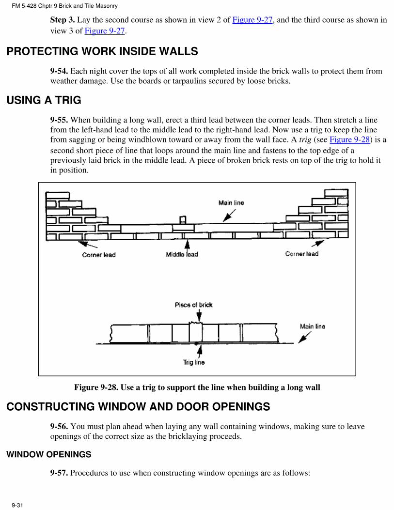
Step 3. Lay the second course as shown in view 2 of Figure 9-27, and the third course as shown in
view 3 of Figure 9-27.
PROTECTING WORK INSIDE WALLS
9-54. Each night cover the tops of all work completed inside the brick walls to protect them from
weather damage. Use the boards or tarpaulins secured by loose bricks.
USING A TRIG
9-55. When building a long wall, erect a third lead between the corner leads. Then stretch a line
from the left-hand lead to the middle lead to the right-hand lead. Now use a trig to keep the line
from sagging or being windblown toward or away from the wall face. A trig (see Figure 9-28) is a
second short piece of line that loops around the main line and fastens to the top edge of a
previously laid brick in the middle lead. A piece of broken brick rests on top of the trig to hold it
in position.
Figure 9-28. Use a trig to support the line when building a long wall
CONSTRUCTING WINDOW AND DOOR OPENINGS
9-56. You must plan ahead when laying any wall containing windows, making sure to leave
openings of the correct size as the bricklaying proceeds.
WINDOW OPENINGS
9-57. Procedures to use when constructing window openings are as follows:
FM 5-428 Chptr 9 Brick and Tile Masonry
9-31

Planning. First, find out the specified distance from the foundation to the bottom of the
window sill. The height of the wall to the top of a full course must equal that distance. Now,
calculate how many courses will bring the wall up to that height. For example, if the sill is 4
feet 4 1/4 inches above the foundation using 1/2-inch mortar joints, you must lay 19 courses
before you reach the bottom of the sill. Calculate it this way: each brick plus one mortar
joint equals 2 1/4 plus 1/2 equals 2 3/4 in per course, and 4 feet 4 1/4 inches divided by 2
3/4 inches equals 19 courses.
●
Marking. Lay the corner leads and the wall in between them so that the top of the last
course is not more than 1/4 inch above the top of the window frame. Use a pencil to mark
the top of each course on the window frame itself. If the mark for the top of the last course
does not come out to the proper level, change the joint thickness you plan to use until it
does.
●
Laying the brick. Lay the corner leads with joints of the calculated thickness. When the
corner leads are built, install a line as described earlier and stretch it across the bottom of
the window openings. Lay the brick for the wall between the leads up to sill height using
the calculated joint thickness. If the window openings are planned properly, you can lay the
face tier brick with a minimum of cutting.
●
Laying the rowlock sill course. When the wall reaches sill height, lay the rowlock sill
course as shown in Figure 9-29 below. Pitch the course downward away from the window.
The rowlock normally takes up a vertical space equal to two courses of brick. Finish the
exterior joint surfaces carefully to make them watertight.
●
Placing the frame. As soon as the mortar sets, place the window frame on the rowlock sill
course, bracing it firmly until the masonry reaches about ingathered of the way up the
frame. (But do not remove the braces for several days so that the wall above the window
frame sets properly). Now lay the rest of the wall around the frame until the top of the last
course is not more than 1/4 inch above the window frame
●
Figure 9-29. Constructing a window opening
DOOR OPENING
9-58. Use the same procedure to construct a door opening (see Figure 9-30) as for a window
FM 5-428 Chptr 9 Brick and Tile Masonry
9-32

opening. To anchor the door frame to the masonry using screws or nails, cut pieces of wood to the
size of a half closure and lay them in mortar the same as brick. Place the wood blocks at several
points along the top and sides of the door opening.
Figure 9-30. Constructing a door opening
LINTELS
9-59. The lintel above a window or door carries the weight of the wall above it. It rests on top of
the last brick course that is almost level with the top of the window or door frame, and its sides
bed firmly in mortar. Close any space between the window or door frame and the lintel with
blocking, and weather-strip it with bituminous materials. Then continue the wall above the
window or door when the lintel is in place.
CONSTRUCTION
9-60. Lintels are made from steel, precast reinforced-concrete beams, or wood. Do not use wood
lintels if possible. In reinforced brick masonry, properly installed steel reinforcing bars support the
brick above wall openings.
INSTALLATION
9-61. The placement and relative positioning of lintels are determined by both the wall thickness
and the type of window or door specified. This information is usually on the building drawings. If
the lintel size is not specified, Table 9-5 gives size and quantities of double-angle steel and wood
lintels to use for various opening widths in both 8- and 12-inch walls. Figures 9-31 and 9-32
below show how to place different kinds of lintels in different wall thickness. Figure 9-31 shows
FM 5-428 Chptr 9 Brick and Tile Masonry
9-33

how to install a doubleness steel lintel in an 8-inch wall. The angle is 1/4-inch thick, which allows
the two angle legs that project up into the brick to fit exactly into the 1/2-inch joint between the
face and backing ties.
Table 9-5. Lintel sizes for 8-inch and 12-inch walls
Wall
Thickness,
in Inches
Span
3 Feet 4 Feet, Steel
Angles*
5 Feet, Steel
Angles*
6 Feet, Steel
Angles*Steel Angles Wood
8 2-3 x 3 x 1/4 2 x 8
2-2 x 4
2-3 x 3 x 1/4 2-3 x 3 x 1/4 2-3 1/2 x 3 1/2 x
1/4
12 3-3 x 3 x 1/4 2 x 12
2-2 x 6
3-3 x 3 1/4 3-3 1/2 x 3 1/2 x
1/4
3-3 1/2 x 3 1/2 x
1/4
7 Feet, Steel
Angles*
8 Feet, Steel
Angles*
2-3 1/2 x 3 1/2 x
1/4
3-4 x 4 x 1/4
2-3 1/2 x 3 1/2 x
1/4
3-4 x 4 x 4 1/4
* Wood lintels should not be used for spans over 3 feet since they will burn out in case of fire and
allow
the bricks to fall.
Figure 9-31. Installing a double-angle steel lintel in an 8-inch wall
FM 5-428 Chptr 9 Brick and Tile Masonry
9-34

Figure 9-32. Installing lintels in a 12-inch wall
CORBELING
9-62. Corbeling consists of brick courses projecting beyond the wall face to increase its thickness
or form a self-supporting shelf or ledge (see Figure 9-33). The portion of a chimney exposed to
weather is frequently corbeled to increase its thickness for better weather resistance. Corbeling
usually requires various-sized bats ( a broken brick with one end whole, the other end broken off).
Use headers as much as possible, but the first projecting course can be a stretcher course if
necessary. No course should extend more than 2 inches beyond the course underneath it, and the
total corbel projection should not be greater than the wall thickness.
FM 5-428 Chptr 9 Brick and Tile Masonry
9-35

Figure 9-33. Constructing a corbeled brick wall
9-63. Corbel construction requires good workmanship for maximum strength. Make all mortar
joints carefully and fill them completely with mortar. When the corbel must withstand large loads,
consult a qualified engineer.
ARCHES
9-64. A well-constructed brick arch can support a heavy load, mainly due to its curved shape.
Figure 9-34 shows two common arch shapes.
FM 5-428 Chptr 9 Brick and Tile Masonry
9-36

Figure 9-34. Common shapes
Brick arches require full mortar joints. Note that the joint width is narrower at the bottom of the
arch than at its top, but it should not narrow to less than 1/4 inch at any point. As laying
progresses, make sure that the arch does not bulge out of position.
BUILDING A TEMPLET
9-65. Construct a brick arch over a temporary wood support called a templet (see Figure 9-35) that
remains in place until the mortar sets.
Figure 9-35. Using a templet to construct an arch
You can obtain the templet dimensions from the construction drawings. For arches spanning up to
6 feet, use 3/4-inch plywood to make the templet. Cut two pieces to the proper curvature and nail
them to 2 by 2 spaces that provide a surface wide enough to support the brick. Use wedges to hold
FM 5-428 Chptr 9 Brick and Tile Masonry
9-37

the templet in position until the mortar hardens enough to make the arch self-supporting. Then
drive out the wedges.
LAYING OUT THE ARCH
9-66. Lay out the arch carefully to avoid cutting the brick. Use an odd number of bricks so that the
key or middle brick falls into place at the exact arch center or crown. The key or middle brick is
the last one laid. To determine how many bricks an arch requires, lay the templet on its side on
level ground and set a trial number of bricks around the curve. Adjust the number of bricks and
the joint spacing (not less than 1/4 inch) until the key brick is at the exact center of the curve.
Mark the positions of the bricks on the templet and use them as a guide when laying the brick.
WATERTIGHT WALLS
9-67. Water does not usually penetrate brick walls through the mortar or brick, but through cracks
between the brick and the mortar. Cracks are more likely to occur in head joints than in bed joints.
PREVENTING CRACKS
9-68. Sometimes a poor bond between the brick and the mortar causes cracks to form and
sometimes mortar shrinkage is responsible. Do not change the position of a brick after the mortar
begins to set, because this destroys the bond between the brick and mortar and a crack will result.
Wet high-suction bricks and other bricks as necessary during hot weather so that they do not
absorb too much moisture from the mortar and cause it to shrink. You can reduce both the size
and number of cracks between the mortar and the brick by tooling the exterior faces of all mortar
joints to a concave finish. To obtain watertightness, completely fill all head and bed joints with
mortar.
PARGING
9-69. Figure 9-36 shows a good way to produce a watertight wall called parging or back
plastering. Parging means to plaster the back of the brick in the face tier with not less than 3/8
inch of rich cement mortar before laying the backing bricks. Because you cannot plaster over
mortar protruding from the joints, first cut all joints flush with the back of the face tier.
Figure 9-36. Parging the back of the face tier for watertightness
FM 5-428 Chptr 9 Brick and Tile Masonry
9-38

WATERPROOF WITH MEMBRANES
9-70. If a wall is subject to much water pressure, use a membrane to waterproof it. A properly
installed membrane adjusts to any shrinkage or settlement without cracking.
CONSTRUCTING DRAINS
9-71. If the wall is subject to much groundwater, or the surrounding soil does not drain well,
construct tile drains or French drains around the wall base (see Figure 9-37). If drainage tile is not
available, an 8-inch layer of coarse loose rock or stone will do the job. This is called a French
drain.
Figure 9-37. Draining a wall around its foundation
REPAIRING CRACKS
9-72. Before applying waterproof or portland-cement paints, repair all cracks. To repair mortar
joint cracks, first chip out the mortar around the full width of the crack to a depth of about 2
inches. Carefully scrub the hole with clean water. While the hole surfaces are still wet, apply a
coating of cement mortar made with enough water to form a thick liquid. Before the coating sets,
fill the hole with prehydrated mortar, which is recommended for tuck-pointing in paragraph 9-90.
NOTE: Repair cracks in bricks the same way as cracks in concrete (see paragraphs 5-95 and
5-105).
USING WATERPROOF COATING
9-73. Walls can be waterproofed in three ways:
Bituminous mastic. To make a below-grade foundation wall watertight, apply two coats of
bituminous mastic to the exterior brick surface. You can apply asphalt or coal tar pitch
using a mop.
●
Waterproof paints. You can improve the watertightness of above-grade brick walls by●
FM 5-428 Chptr 9 Brick and Tile Masonry
9-39

applying a transparent, waterproof paint, such as a water solution of sodium silicate.
Varnish, certain white and color waterproof paints, and high-quality oil-base paints are also
effective. Apply them according to the directions.
Portland-cement paint. This paint generally gives excellent results if you apply it when the
wall is at least 30 days old. Use type 2, class A portland-cement paint and follow the
manufacturer's instructions for mixing and applying it. Remove all efflorescence from the
surface (see paragraph 9-95) and dampen the surface with a water spray before applying the
paint. Use white-wash or calcimine-type brushes or a spray gun, but spraying reduces the
paint's rain resistance.
●
FIRE-RESISTANT BRICK
9-74. To line furnaces, incinerators, and so forth, use fire-resistant brick to protect the supporting
structure or outer shell from intense heat. The outer shell probably consists of common brick or
steel, neither of which has good heat resistance.
TYPES
9-75. The two types of fire-resistant brick are fire bricks and silica bricks.
Fire bricks are made from a special clay, called fire clay, or that withstand higher
temperatures and are heavier and usually larger than common brick. Their standard size is 9
by 4 1/2 by 2 1/2 inches.
●
Silica bricks resist acid gases; however, do not use silica brick if it will be alternately heated
and cooled. Therefore, you should line most incinerators with fire brick rather than with
silica brick.
●
LAYING FIRE BRICK
9-76. Fire brick requires thin mortar joints, especially if the brick is subject to such high
temperatures as those in incinerators. Store the bricks in a dry place until you use them.
Mortar
9-77. Use a mortar made from fire clay and water mixed to the consistency of thick cream. Obtain
fire clay by grinding used fire brick.
Laying procedure
9-78. To lay fire bricks, use the following proedures:
Step 1. Dip the brick in the mortar, covering all surfaces except the top bed.
Step 2. Lay the brick and tap it firmly into place with a bricklayer's hammer.
Step 3. Make the mortar joints as thin as possible, and fit the bricks together tightly. Remember
that any heat that migrates through the cracks between the fire bricks will damage the outside shell
of the incinerator or furnace.
Step 4. Stagger the head joints the same way you do in ordinary brick construction. The bricks in
one course should lap those in the course underneath by one-half brick.
FM 5-428 Chptr 9 Brick and Tile Masonry
9-40

LAYING SILICA BRICK
9-79. Lay silica bricks without mortar, fitting them so close together that they fuse at the joints at
high temperatures. Stagger the head joints as you do in ordinary brick construction.
TYPES OF WALLS
9-80. The basic types of walls are: hollow and partition.
HOLLOW
9-81. Hollow walls consist of an inner and an outer wythe separated by an air space. The two most
important types of hollow walls are the cavity wall and the rowlock wall. Partition walls divide
the interior space in a one-story building. They may be load-bearing or nonload-bearing walls.
Cavity
9-82. A cavity wall is a watertight wall that can be plastered without furring or lathing. It looks the
same on the exterior as a solid wall without header courses (see Figure 9-38). Instead of headers,
metal ties are installed every sixth course on a 24-inch center that holds the two tiers together. To
prevent water penetration to the inner tier, angle the ties downward from the inner to outer tier. A
2-inch cavity or air space between the two brick wythes drains any water that penetrates the outer
tier. The air space also provides good heat and sound insulation. The bottom of the cavity is above
ground level. It is drained by weep holes in the vertical joints in the first course of the exterior tier.
Make the weep holes simply by leaving the mortar out of the joint. Space them about a 24-inch
interval.
Figure 9-38. Construction details of a cavity wall
Rowlock
FM 5-428 Chptr 9 Brick and Tile Masonry
9-41

9-83. A rowlock is a header laid on its face or edge. A rowlock also has a 2-inch cavity between
the wythes as shown in Figure 9-39. In this type of rowlock wall, the face tier is loose like a
common-bond wall having a full header course every seventh course. However, the bricks in the
inner or backing tier are laid on edge. A header course ties the outer and backing ties together. For
an all-rowlock wall, lay the brick on edge in both the inner and outer tiers. Install a header course
every fourth course (that is, three rowlock courses to every header course). The rowlock wall is
not as watertight as the cavity wall, because water will follow along any crack in the header
course and pass through to the interior surface.
Figure 9-39. Construction details of a rowlock wall
PARTITION
9-84. A partition wall that carries very little load requires only one wythe producing a wall 4
inches thick. You can lay a wall of this thickness without headers.
LAYING HOLLOW AND PARTITION WALLS
9-85. Lay the brick for hollow and partition walls as described starting in paragraph 9-29 for
making bed joints (f), head joints (h), cross joints (j), and closures (K and l). Use a line the same
as for a common bond wall. Erect the corner leads first, and then build the wall between them.
MANHOLES
9-86. Sewer systems require manholes (see Figure 9-40) for cleaning and inspection. The
manhole size largely depends on the sewer size. Manholes are either circular or oval to reduce the
stresses from both water and soil pressures. A 4-foot diameter manhole is satisfactory for small,
FM 5-428 Chptr 9 Brick and Tile Masonry
9-42

straight-line sewers. Construction details of a typical manhole are shown in view 2 of Figure 9-40.
Although both the bottom and walls of a manhole are sometimes made from brick, the bottom is
normally made from concrete because it is easier to cast in the required shapes. However, you can
construct the walls more economically from brick, because it requires no form work.
Figure 9-40. Construction details of a sewer manhole
WALL THICKNESS
9-87. The wall thickness of a manhole depends on its depth and diameter. You can use an 8-inch
wall for manholes up to 8 feet in diameter and less than 15 feet deep. A qualified engineer should
design any manholes over 15-feet deep.
MANHOLE CONSTRUCTION
9-88. Use only headers for an 8-inch wall, but no line. Use a mason's level to make sure that all
bricks in a particular course are level. Span the manhole with a straightedge or place a mason's
level on a straight surfaced 2 by 4 across the manhole, to make sure the brick rises to the same
level all around. Because the wall appearance is not important, some irregularities in both brick
position and mortar joint thickness are permissible. All joints should be either full or closure
FM 5-428 Chptr 9 Brick and Tile Masonry
9-43

joints.
Laying the first course. Place a 1-inch mortar bed on the foundation. Lay the first course on
the mortar bed, followed by the succeeding header courses.
●
Corbeling. To reduce the manhole diameter to fit the frame and cover, corbel the brick
inward as shown in view 2 of Figure 9-40 above. No brick should project more than 2
inches beyond the brick underneath it. Space the wrought-iron steps about every 15 inch
vertically, and embed them in a cross mortar joint. When complete, plaster the wall on the
outside at least 3/8-inch thick with the same mortar used in laying the brick.
●
Placing. Spread a 1-inch mortar bed on top of the last course, and place the base of the
manhole frame in the bed.
●
SUPPORTING BEAMS ON A BRICK WALL
9-89. The following beams are used on brick walls.
Wood Beams. Figure 9-41 shows how to support a wood beam on a brick wall.
Note the wall tie. Keep mortar away from the beam as much as possible,
because wood can dry rot when completely encased in mortar. Protect the
beam with a beam box (see Figure 9-41). Cut the end of the beam at an angle
so that, in case of fire, it will fall without damaging the wall above the beam.
For an 8- or 12-inch wall, let the beam bear on the full width of the inside tier.
●
Steel Beams. When a brick wall must support a steel beam, insert a steel
bearing plate set in mortar under the beam. A properly designed bearing plate
prevents the beam from crushing the brick. The size of the bearing plate
depends on the size of the beam and the load it carries.
●
Figure 9-41. Supporting a wood beam on a brick wall
FM 5-428 Chptr 9 Brick and Tile Masonry
9-44

MAINTAINING AND REPAIRING BRICK WALLS
9-90. A well-constructed brick masonry wall requires little maintenance or repair. It
can be more expensive to repair old masonry properly than to completely remove and
replace just the disintegrated portion. Good mortar, proper joint finishing, and
adequate flashing add little to the initial cost, but reduce maintenance cost throughout
the life of the masonry.
TUCK-POINTING
9-91. Tuck-pointing during routine maintenance means to cut out all loose and
disintegrated mortar to a depth of at least 1/2 inch and replace it with new mortar.
Use a chisel having a cutting edge about 1/2 inch wide. To stop leakage, cut out all
the mortar in the affected area, and replace it with new mortar.
PREPPING THE MORTAR JOINT
9-92. After cutting out the defective mortar, remove all dust and loose material with a
brush or a water jet. If you use a water jet, no further joint wetting is required. If not,
moisten the joint surfaces.
PREPARING MORTAR FOR TUCK-POINTING
9-93. Use portland-cement-lime prehydrated Type S mortar or prehydrated prepared
mortar made from type II masonry cement. Prehydrating mortar greatly reduces the
amount of shrinkage. Mix the dry ingredients with just enough water to produce a
damp mass of a consistency that retains its form when you compress it into a ball
with your hands. Allow the mortar to stand for at least 1 hour, but not more than 2
hours. Then mix the mortar with enough water to produce a stiff, but workable
consistency.
FILLING THE JOINT
9-94. Filling a joint with mortar is called repointing and is done with a pointing
trowel. Before filling the joint, allow the moisture used in preparing the joint to
absorb. Then pack the prepared prehydrated mortar into the joint tightly in thin layers
about 1/4 inch thick, and finish them to a smooth concave surface using a pointing
tool. Push the mortar into the joint in one direction only from the starting point, using
a forward motion to reduce the risk of forming air pockets.
CLEANING NEW BRICK AND REMOVING STAINS
9-95. A skilled bricklayer can build a masonry wall that is almost free from mortar
stains. However, most new brick walls still need some cleaning.
Step 1. Remove large mortar particles adhering to brick with a putty knife or chisel.
Remove mortar stains with an acid solution of one part commercial muriatic acid to
nine parts water. Acid must be poured into the water, not the water into the acid.
Before applying the acid, thoroughly soak the masonry surface with water to prevent
FM 5-428 Chptr 9 Brick and Tile Masonry
9-45

the stain from being drawn into the brick pores.
Step 2. Apply the acid solution with a long-handled stiff-fiber brush. Take all
precautions to prevent the acid from getting on your hands, arms, or clothing, and
wear goggles to protect your eyes. Protect door and window frames. Scrub an area of
15 to 20 square feet with the acid solution, and then wash it down immediately with
clear water. Make sure that you remove all acid before it can attack the mortar joints.
Step 3. Removing any efflorescence. Efflorescence is a white deposit that forms on
the surface of brick walls. It consists of soluble salts leached from the brick by
penetrating water that dissolves the salt in the brick. When the water evaporates, the
salt remain. Because efflorescence requires the presence of both water and salts,
proper brick selection and a dry wall will keep it to a minimum. However, if simply
scrubbing the wall with water and a stiff brush does not remove the efflorescence,
you can remove it with the acid solution described above for cleaning new masonry.
CLEANING OLD BRICK
9-96. The principal ways to clean old brick masonry are sandblasting, steam cleaning
with water jets, or using cleaning compounds. The type of brick and the nature of the
stain will determine which method you use. Many cleaning compounds that do not
affect the brick will damage the mortar. Rough-textured brick is more difficult to
clean than smooth-textured brick.
Sometimes you cannot clean rough-textured brick without removing part of the brick
itself, which changes the appearance of the wall.
SANDBLASTING
9-97. Sandblasting consists of using compressed air to blow hard sand through a
nozzle against a dirty surface, thereby removing enough of the surface to eliminate
the stain. Place a canvas screen around the scaffold to salvage most of the sand. The
disadvantage of sandblasting is that it leaves a rough-textured surface that collects
soot and dust. Moreover, sandblasting usually cuts so deeply into the mortar joints
that you may have to repoint them. After sandblasting, apply a transparent
waterproofing paint to the surface to help prevent future soiling by soot and dust.
Never sandblast glazed surfaces.
STEAM CLEANING WITH WATER JETS
9-98. Steam cleaning means to project a finely divided spray of steam and water at
high velocity against a dirty surface. This removes grime effectively without
changing the surface texture, which gives steam cleaning an advantage over
sandblasting.
Equipment. Use a portable, truck-mounted boiler to produce the steam at a
pressure ranging from 140 to 150 psi. Each cleaning nozzle requires about a
12-horse-power boiler. The velocity of the steam and water spray as it strikes
the surface is more important than the volume of the spray.
●
Procedure. Use one garden hose to carry water to the cleaning nozzle and●
FM 5-428 Chptr 9 Brick and Tile Masonry
9-46

another to supply rinse water. Experiment to determine the best angle and
distance from the wall to hold the nozzle. Adjust the steam and water valves
until you obtain the most effective spray. Pass the nozzle back and forth over
no more than a 3-square-feet area at one time. Rinse it immediately with clean
water before moving to the next area.
Additives. To aid cleaning action, add sodium carbonate, sodium bicarbonate,
or trisodium phosphate to the water entering the nozzle. Reduce a lot of the salt
or efflorescence remaining on the surface by washing it down with water
before and after steam cleaning.
●
Hand tools. Use steel scrapers or wire brushes to remove any hardened
deposits that remain after steam cleaning. Be careful not to cut into the surface.
After removing the deposits, wash down the surface with water and steam and
clean it again.
●
CLEANING COMPOUNDS
9-99. You can use one of several cleaning compounds, depending on the nature of the
stain. Most cleaning compounds contain salts that will cause efflorescence if the
cleaning solution penetrates the surface. You can prevent this by thoroughly wetting
the surface before applying the solution. You can remove whitewash, calcimine, or
paint coatings with a solution of one part acid to five parts water. Use fiber brushes to
scrub the surface with the solution while it is still foaming. After removing the
coating, wash down the wall with clean water until you remove the acid completely.
PAINT REMOVERS
9-100. Apply paint remover with a brush to remove oil paint, enamels, varnishes,
shellacs, or glue sizing. Leave the remover on until the coating is soft enough to
scrape off with a putty knife. The following are effective paint removers:
Commercial. When using commercial paint removers, the manufacturer's
instructions should be followed.
●
Chemical. Use a solution of 2 pounds of trisodium phosphate in 1 gallon of hot
water. Another solution is 1 1/2 pounds of caustic soda in 1 gallon of hot
water.
●
Blasting and torching. Sandblasting or burning off with a blowtorch will also
remove paint.
●
REMOVING MISCELLANEOUS STAINS
9-101. The following are procedures for removing different types of stains:
Iron stains. Mix seven parts lime-free glycerin into a solution of one part
sodium citrate in six parts lukewarm water. Add whiting or kieselguhr to make
a thick paste and apply it to the stain with a trowel. Scrape off the paste when it
dries. Repeat the procedure until the stain disappears; then, wash down the
surface with water.
●
Tobacco stains. Dissolve 2 pounds of trisodium phosphate in 5 quarts of water.
Next, in an enameled pan, mix 12 ounces of chloride of lime in enough water
●
FM 5-428 Chptr 9 Brick and Tile Masonry
9-47

to make a smooth thick paste. Then mix the trisodium phosphate with the lime
paste in a 2-gallon stoneware jar. When the lime settles, draw off the clear
liquid and dilute it with an equal amount of water. Make a stiff paste by mixing
the clear liquid with powdered talc, and apply it to the stain with a trowel
followed by washing the surface.
Smoke stains. Apply a smooth, stiff paste made from trichlorethylene and
powdered talc. Cover the container when you are finished to prevent
evaporation. If a slight stain still remains after several applications, wash down
the surface and then follow the procedure described above for removing
tobacco stains. Use the paste only in a well-ventilated space because its fumes
are harmful.
●
Copper and bronze stains. Mix one part ammonium chloride (salammoniac) in
dry form to four parts powdered talc. Add ammonia water and stir the solution
to obtain a thick paste. Apply the paste to the stain with a trowel, and allow it
to dry. Several applications may be necessary. Then wash down the surface
with clear water.
●
Oil stains. Make a solution of 1 gallon trisodium phosphate to 1 gallon of
water, adding enough whiting to form a paste. Trowel the paste over the stain
in a layer 1 1/2 inch thick, and allow it to dry for 24 hours. Remove the paste
and wash down the surface with clean water.
●
FLASHING
9-102. Flashing is an impermeable membrane placed in brick masonry at certain
locations to exclude water or to collect any moisture that penetrates the masonry and
direct it to the wall exterior. Flashing can be made from copper, lead, aluminum, or
bituminous roofing paper. Copper is best, although it stains the masonry as it
weathers. Use lead-coated copper if such staining is unacceptable. Bituminous
roofing papers are cheapest, but not as durable. They will probably require periodic
replacement in permanent construction, and their replacement cost is greater than the
initial cost of installing high-quality flashing. Corrugated copper flashing sheets
produce a good bond with the mortar. They also make interlocking watertight joints
at points of overlap.
PLACEMENT
9-103. Install flashing at both the head and sill of window openings and at the
intersection between a wall and roof. The flashing edges should turn upward as
shown in Figure 9-42 to prevent drainage into the wall. Always install flashing in
mortar joints. You can provide drainage for the wall above the flashing either by
placing 1/4-inch cotton-rope drainage wicks at 18-inch spacings in the mortar joint
just above the flashing or placing dowels in the proper mortar joint as you lay the
brick and then remove them to make drainage holes. Where chimneys pass through
the roof, the flashing should extend completely through the chimney wall and turn
upwards 1 inch against the flue lining.
FM 5-428 Chptr 9 Brick and Tile Masonry
9-48

Figure 9-42. Installing flashing at window opening
INSTALLATION
9-104. Using the following steps to install flashing:
Step 1. Spread a 1/2-inch mortar bed on top of the brick, and then push the flashing
sheet down firmly into the mortar. Spread a 1/2-inch mortar bed on the flashing, and
then force the brick or sill onto the top of the flashing.
Step 2. Figure 9-42 above shows the proper flashing installations at both the head
and the sill of a window. Note that the flashing fits under the face tier of brick at the
steel lintel, then bends behind the face tier and over the top of the lintel.
Step 3. Figure 9-43 shows how to install flashing between the roof and the wall to
prevent leakage at the intersection. Fit and caulk the upper end of the flashing into
the groove of the raggle block as shown in Figure 9-43.
FM 5-428 Chptr 9 Brick and Tile Masonry
9-49

Figure 9-43. Flashing installation at intersection of roof and walls
FREEZE PROTECTION DURING CONSTRUCTION
9-105. Masonry walls built during cold weather may leak, because either the mortar
froze before it set or the materials and walls were not adequately protected against
freezing temperatures. During cold weather, prevent future wall leakage by--
Storing materials properly.●
Heating mortar ingredients.●
Heating masonry units.●
Taking special precautions during placement.●
Protecting completed work.●
STORING MATERIALS
9-106. Careless materials storage can cause time delays and/or contribute to poor
workmanship, because you must remove all ice and snow and thaw masonry units
before construction can proceed. Instead, completely cover all masonry units and
mortar materials with tarpaulins or building paper. Store them on plank platforms
either thick enough or raised high enough to prevent moisture absorption from the
ground.
HEATING MORTAR INGREDIENTS
9-107. Heat both water and sand to a temperature not exceeding 160oF. Make sure
that the temperature of the mortar--when you use it--is at least 70oF but not more
than 120oF. Use steel mortar boxes on small jobs, and raise them about 1 foot above
the ground so that you can supply heat to keep the mortar warm after mixing. Never
add salt water to mortar to lower its freezing point.
FM 5-428 Chptr 9 Brick and Tile Masonry
9-50

CONSIDERING TEMPERATURE VARIATIONS
9-108. If the outside air temperature is below 40oF, the brick temperature when you
lay it should be above 40oF on both sides of the masonry for at least 48 hours for
Type M or S mortar, or for at least 72 hours for Type N mortar. If you use
high-early-strength cement, reduce these time periods to 24 and 48 hours,
respectively. Note that the use of high-early-strength cement in a mortar does not
alter the setting rate much, but it does increase the rate of strength gain, thereby
providing greater resistance to further freeze damage.
HEATING MASONRY UNITS
9-109. To prevent the warm mortar from cooling suddenly as it contacts the cold
bricks, preheat all masonry units to about 40oF whenever the outside temperature is
below 18oF. This requires careful planning and timing. When heat is required,
provide inside brick storage so that you can supply heat at minimum expense.
LAYING PRECAUTIONS
9-110. In below-freezing weather, sprinkle any high-suction brick with warm water
just before you lay it. Never lay masonry units on snow- or ice-covered mortar beds,
because little or no bond will exist between the mortar and units when the base
thaws. Keep the tops of unfinished walls carefully covered whenever work stops. If
the covering comes off and ice or snow collects on the wall top, remove it with live
steam before continuing.
PROTECTING COMPLETED WORK
9-111. How you protect masonry from freezing varies with weather conditions and
the individual job. Job layout, desired rate of construction, and the prevailing weather
conditions all determine the amount of protection and the type of heat necessary to
maintain above-freezing temperatures within the wall until the mortar sets properly.
MATERIAL QUANTITIES REQUIRED
9-112. See Table 9-6 for the quantities of brick and mortar required for various
masonry wall thickness.
Table 9-6. Quantities of materials required for brick walls
Wall
Area
in,
Square
Feet
Wall Thickness, in Inches
4 8 12 16
Number
of
Bricks
Mortar,
in
Cubic
Feet
Number
of
Bricks
Mortar,
in
Cubic
Feet
Number
of
Bricks
Mortar,
in
Cubic
Feet
Number
of
Bricks
Mortar,
in
Cubic
Feet
1 6.17 .08 12.33 .2 18.49 .32 24.65 .44
FM 5-428 Chptr 9 Brick and Tile Masonry
9-51

10 61.7 .8 123.3 2 184.9 3.2 246.5 4.4
100 617 8 1,233 20 1,849 32 2,465 44
200 1,234 16 2,466 40 3,698 64 4,930 88
300 1,851 24 3,699 60 5,547 96 7,395 132
400 2,468 32 4,932 80 7,396 128 9,860 176
500 3,085 40 6,165 100 9,245 160 12,325 220
600 3,702 48 7,398 120 11,094 192 14,790 264
700 4,319 56 8,631 140 12,943 224 17,253 308
800 4,936 64 9,864 160 14,792 256 19,720 352
900 5,553 72 10,970 180 16,641 288 22,185 396
1,000 6,170 80 12,330 200 18,490 320 24,650 440
NOTE: Quantities are based on a 1/2-inch-thick mortar joint; a 3/8-inch-thick joint uses
80 percent
of these quantities; a 5/8-inch-thick joint uses 120 percent of these quantities.
SECTION IV. REINFORCED BRICK MASONRY
APPLICATIONS AND MATERIALS
9-113. When added strength is needed, brick walls, columns, beams, and foundations
are reinforced the same as in concrete construction.
APPLICATIONS
9-114. Because brick masonry in tension has low strength compared with its
compressive strength, it is reinforced with steel when subject to tensile stresses. Like
concrete construction, the reinforcing steel is placed in either the horizontal or
vertical mortar joints of beams, columns, walls, and footings. Reinforced brick
structures can resist earthquakes that would severely damage nonreinforced brick
structures. The design of such structures by qualified engineers is similar to that of
reinforced concrete structures.
MATERIALS
9-115. Materials used for reinforced brick are--
Brick. The same brick is used for reinforced brick masonry as for ordinary
brick masonry. However, it should have a compressive strength of at least
2,500 pounds per square inch.
●
FM 5-428 Chptr 9 Brick and Tile Masonry
9-52

Steel. The reinforcing steel is the same as that in reinforced concrete and is
fabricated and stored the same way. Do not use high-grade steel except in
emergencies, because masonry construction requires many sharp bends.
●
Mortar. Use Type N mortar for its high strength.●
Wire. Use 18-gage, soft-annealed iron wire to tie the reinforcing steel.●
CONSTRUCTION METHODS
9-116. Reinforcing steel can be placed in both horizontal and vertical mortar joints.
LAYING REINFORCED BRICK
9-117. Lay the brick the same way as ordinary brick masonry, with mortar joints 1/8
inch thicker than the diameter of the reinforcing bar. This provides 1/16 inch of
mortar between the brick surface and the bar. Thus, large steel bars require mortar
joints thicker than 1/2 inch.
PLACING THE STEEL
9-118. Embed all reinforcing steel firmly in mortar.
Horizontal bars. Lay horizontal bars in the mortar bed, and then push them
down into position. Spread more mortar on top of the bars, smooth it out until
you produce a second bed joint of the proper thickness. Lay the next course in
this mortar bed, following the same procedure as laying brick without
reinforcing steel.
●
Stirrups. Most stirrups are Z-shaped as shown in Figure 9-44 to fit the mortar
joints. Insert the lower leg under--and contacting--the horizontal bars, which
requires a thicker joint at that point.
●
Vertical bars. Hold vertical bars in the vertical mortar joints with wood
templets having holes drilled at the proper bar spacing, or by wiring them to
horizontal bars. Then lay the brick up around the vertical bars.
●
Spacing. The minimum center-to-center spacing between parallel bars is 1-1/2
times the bar diameter.
●
FM 5-428 Chptr 9 Brick and Tile Masonry
9-53

Figure 9-44. Reinforced brick-masonry beam construction
USING FORMWORK
9-119. Reinforced brick-masonry walls, columns, and footings need no formwork.
However, reinforced brick beams and lintels--which act as beams--require formwork
for the same reason that reinforced concrete beams do.
The form consists only of support for the underside of the beam, no side
formwork. The form for the beam underside is the same and is supported the
same as that for concrete beams.
●
When a beam joins a wall or another beam, cut the form short by 1/4 inch, and
fill the gap with mortar. This allows the lumber to swell and makes form
removal easy.
●
Wait at least 10 days before removing the form from the beam underside.●
BEAMS AND LINTEL CONSTRUCTION
9-120. Lintels are placed above the windows and doors to carry the weight of the
wall above them. Lintels can be made of steel, precast reinforced concrete beams, or
wood.
BEAM DIMENSIONS
9-121. Beam width and depth depend upon brick dimensions, mortar joint thickness,
and the load that the beam will support. However, beam width usually equals the wall
thickness, that is 4, 8, 12, or 16 inches. Beam depth should not exceed approximately
three times its width.
BEAM CONSTRUCTION PROCEDURES
9-122. The following procedures will be used in beam construction:
Step 1. Lay the first course on the form using full head joints, but no bed joint (see
FM 5-428 Chptr 9 Brick and Tile Masonry
9-54

Figure 9-44).
Step 2. Spread a mortar bed about 1/8 inch thicker than the diameter of the horizontal
reinforcing bars on the first course, and embed the bars.
Step 3. Slip the legs of any stirrups under the horizontal bars as shown in Figure
9-44. Be sure to center the stirrup in the vertical mortar joint.
Step 4. After properly positioning the stirrups and the horizontal bars, spread more
mortar on the bed joints if necessary, and smooth its surface. Then lay the remaining
courses in the normal way.
Step 5. Lay all bricks for one course before proceeding to the next course to ensure a
continuous bond between the mortar and steel bars. Often, three or four bricklayers
must work on one beam to spread the bed-joint mortar for the entire course, place the
reinforcing steel, and lay the brick before the mortar sets.
LINTEL CONSTRUCTION
9-123. The steel bars should be 3/8 inch in diameter, or less if you must maintain a
1/2-inch mortar joint. Place the bars in the first and fourth mortar joints above the
opening (see Figure 9-45). They should extend 15 inches into the brick wall on each
side of the opening. Table 9-7 below gives the number and diameter of bars required
for different width wall openings. See paragraph 9-56 for how to place the wall above
a window or door opening.
Figure 9-45. Reinforced brick-masonry lintel construction
Table 9-7. Quantities of bars required for lintels
Width of Wall
Opening, in Feet
Bar Quantity Bar Diameter, in Inches
6 2 1/4
9 3 1/4
FM 5-428 Chptr 9 Brick and Tile Masonry
9-55

12 3 3/8
FOUNDATION FOOTINGS
9-124. Footings are the enlargements at the lower end of a foundation wall, pier, or
column and are required to distribute the load equally.
9-125. Large footings usually require reinforcing steel because they develop tensile
stresses. As in all brick foundations, lay the first course in a mortar bed about 1 inch
thick, spread on the subgrade.
WALL FOOTING
9-126. Figure 9-46 shows a typical wall footing with steel dowels extending above it
to tie the footing and wall together. The number 3 bars running parallel to the wall
prevent perpendicular cracks from forming.
Figure 9-46. Reinforced brick-masonry-wall footing construction
COLUMN FOOTING
9-127. Reinforced brick-column footings are usually square or rectangular as shown
in Figure 9-47. The dowels not only anchor the column to the footing, but transfer
stress from one to the other. Note that both layers of horizontal steel are in the first
mortar joint, which is accepted practice for small bars. When using large bars, place
one layer in the second mortar joint, and reduce the bar spacing in this joint.
FM 5-428 Chptr 9 Brick and Tile Masonry
9-56

Figure 9-47. Reinforced brick-masonry-column footing construction
COLUMNS AND WALLS
9-128. Load-carrying capacity increases when brick columns and walls have steel
reinforcement.
9-129. At least 1 1/2 inches of mortar or brick should cover the reinforcing bars.
Install 3/8-inch diameter steel hoops or ties at every course (see Figure 9-48) to bold
bars in place. Use circular hoops whenever possible. Lap-weld their ends, or bend
them around the reinforcing bars as shown in Figure 9-48.
Holding steel in place. When the column footing is complete, tie the
reinforcing steel to the dowels projecting from the footing. Slip the necessary
number of hoops over the dowels and fasten them temporarily some distance
above the course being laid, but within your reach. You do not need to wire the
hoops to the dowels. Hold the tops of the dowels in position either with a wood
templet or by tying them securely to a hoop near the top of the column.
●
Laying the brick. Lay the brick as described in paragraph 9-20. Place the hoops
in a full mortar bed, and smooth it out before laying the next course. You can
use brick bats in the column core or wherever it is inconvenient or impossible
to use full-size bricks. After laying each course, fill the core and any space
around the reinforcing bars with mortar. Then push any necessary bats into the
mortar until they are completely embedded. Now spread the next mortar bed
and repeat the procedure.
●
FM 5-428 Chptr 9 Brick and Tile Masonry
9-57

Figure 9-48. Reinforced brick-masonry-column construction
9-130. Reinforce brick masonry walls with both horizontal and vertical bars. Place
the bars as described in paragraph 9-117. Then wire the vertical stirrups to the dowels
projecting out of the wall footing.
Constructing corner leads. Place the reinforcing bars in corner leads as shown
in Figure 9-49 below. Use the same size bars as in the rest of the wall, and let
them extend 15 inches. The horizontal bars in the remaining wall should
overlap the corner bars by the same 15 inches. As for beams, you must lay all
brick in one course between the corner leads before laying any other brick,
because you must embed the entire bar in mortar at one time.
●
Laying the remaining wall. As you lay the remaining brick, fill all spaces
around the reinforcing bars with mortar.
●
Figure 9-49. Corner lead for reinforced brick masonry wall
SECTION V. STRUCTURAL CLAY-TILE MASONRY
STRUCTURAL CLAY TILE
9-131. Structural clay tile is either a hollow or cored burned-clay masonry unit
having cores that are parallel either in the vertical or horizontal direction. The
manufacturing process and the type of clay used are the same as it is for brick.
FM 5-428 Chptr 9 Brick and Tile Masonry
9-58

9-132. Hollow masonry units made from burned clay or shale are usually called
simply clay tile. Figure 9-50 shows several common types and sizes. These stretcher
units are made by forcing a plastic clay through special dyes, then cutting the tiles to
size and burning them the same way as brick. The amount of burning depends upon
the tile grade.
Figure 9-50. Corner lead for reinforced brick masonry wall
9-133. The hollow spaces in the tile are called cells, the external wall is called a shell,
and the partitions between cells are called webs. The shell should be at least 3/4 inch
thick and the web 1/2 inch thick.
9-134. Side-construction tile has horizontal cells, whereas end-construction tile has
FM 5-428 Chptr 9 Brick and Tile Masonry
9-59

vertical cells. Neither is better than the other, and both are available in the types
described below.
9-135. The two basic categories of structural clay tile--load-bearing and
nonload-bearing--differ in their characteristics. Load-bearing structural clay tile
further subdivides into three categories: load-bearing wall tile, structural facing tile,
and ceramic glazed structural facing tile. Nonload-bearing structural clay tile further
subdivides into three categories: nonload-bearing partition and furring tile,
fireproofing tile, and screen tile.
LOAD BEARING
9-136. Load-bearing tile has three types, divided by use: wall, facing, and glazed
facing. Load-bearing wall tile includes--
Wall tile for constructing exposed or faced load-bearing walls. This tile carries
the entire load, including the facing of stucco, plaster, stone, or other material.
●
Back-up tile for backing up combination walls of brick or other masonry in
which both the facing and the backing support the wall load. Headers bond the
facing or outer tier to the backing tile. The inside face is scored so that you can
plaster it without lath.
●
9-137. The ASTM covers two grades of wall and back-up tile based on weather
resistance. Grade LB is suitable for general construction that is not exposed to
weathering, or exposed to weathering but protected by at least 3 inches of facing.
Grade LBX can be used in masonry exposed to weathering with no facing material.
Structural facing tile is divided into two classes, based on the thickness of the
face shell: standard and special duty. The ASTM grades each of these classes
by factors affecting appearance.
- Type FTX is suitable for both exterior and interior walls and partitions. It has
an excellent appearance and is easy to clean.
- Type FTS, although inferior in quality to Type FTX, is suitable for both
exterior and interior walls where some surface finish defects are not
objectionable.
●
Ceramic glazed structural facing tile has an exposed surface of either a ceramic
or salt glaze, or a clay coating. Use this tile where you need a stainproof, easily
cleaned surface. It is available in many colors and produces a durable wall
having a pleasing appearance. Ceramic glazed facing tile is divided into two
types and two grades:
- Type I is suitable for general use where only one finished face will be
exposed.
- Type II is suitable for use where the two opposite finished faces will be
exposed.
- Grade S (select) is suitable for use with comparatively narrow mortar joints.
- Grade SS (select sized or ground edge) is suitable for uses requiring very
small variations in face dimensions.
●
NONLOAD BEARING
FM 5-428 Chptr 9 Brick and Tile Masonry
9-60

9-138. Nonload-bearing tile include three types:
Nonload-bearing partition and furring tile.
- Partition tile is suitable for constructing nonload-bearing interior partitions or
for backing nonload-bearing combination walls.
- Furring tile is suitable for lining the wall interiors to provide both a plaster
base and an air space between plaster and the wall.
●
Fireproofing tile protects structural members including steel girders, columns,
and beams.
●
Screen tile is available in a large variety of patterns, sizes, and shapes, and in a
limited number of colors. The surfaces may be smooth, scored, combed, or
roughened. Screen tile is divided into two types and three grades:
- Type STX has an excellent appearance and minimum size variation.
- Type STA varies more in size.
- Grade SE has high resistance to weathering, freezing, and thawing.
- Grade ME has moderate resistance to weathering.
- Grade NE is suitable for interior use only.
●
SPECIAL UNITS
9-139. Besides the standard units shown in Figure 9-50 above you can order special
clay tile units to use at windows, door openings, and at corners. Consult a
manufacturer's catalog for any special units you need.
QUANTITIES OF MATERIALS REQUIRED
9-140. Tables 9-8 and 9-9 below give the number of structural clay tiles--both side
construction and end construction--and the amount of mortar required for walls of
different thickness covering varying areas.
Table 9-8. Quantities of materials required for side construction of hollow clay-tile walls
4-inch thick wall and 4 x 5 x
12-inch
tile
8-inch thick wall and 8 x 5 x
12-inch
tile
Wall Area, in
Square Feet
Number of Tiles Mortar, in
Cubic Feet
Number of Tiles Mortar, in
Cubic Feet
1 2.1 .045 2.1 .09
10 21 .45 21 .9
100 210 4.5 210 9.0
200 420 9.0 420 18
300 630 13.5 630 27
FM 5-428 Chptr 9 Brick and Tile Masonry
9-61

400 840 18.0 840 36
500 1,050 22.5 1,050 45
600 1,260 27.0 1,260 54
700 1,470 31.5 1,470 63
800 1,680 36.0 1,680 72
900 1,890 40.5 1,890 81
1,000 2,100 45.0 2,100 90
NOTE: Quantities are based on 1/2-inch thick mortar joints.
Table 9-9. Quantities of materials required for end construction of hollow clay-tile walls
4-inch thick wall
and 4 x 12 x 12-
inch tile
6-inch thick wall
and 6 x 12 x 12-
inch tile
8-inch thick wall
and 8 x 12 x 12-
inch tile
10-inch thick wall
and 10 x 12 x 12-
inch tile
Wall
Area,
in
Square
Feet
Number
of Tiles
Mortar,
in
Cubic
Feet
Number
of Tiles
Mortar,
in
Cubic
Feet
Number
of Tiles
Mortar,
in
Cubic
Feet
Number
of Tiles
Mortar,
in
Cubic
Feet
1 .93 .025 .93 .036 .93 .049 .93 .06
10 9.3 .25 9.3 .36 9.3 .49 9.3 .6
100 93 2.5 93 3.6 93 4.9 93 6
200 186 5.0 186 7.2 186 9.8 186 12
300 279 7.5 279 10.8 279 14.7 279 18
400 372 10.0 372 14.4 372 19.6 372 24
500 465 12.5 465 18.0 465 24.5 465 30
600 558 15.0 558 21.6 558 29.4 558 36
700 651 17.5 651 25.2 651 34.3 651 42
800 744 20.0 744 28.8 774 39.2 774 48
900 837 22.5 837 32.4 837 44.1 837 54
1,000 930 25.0 930 36.0 930 49.0 930 60
FM 5-428 Chptr 9 Brick and Tile Masonry
9-62

NOTE: Quantities are based on 1/2-inch thick mortar joints.
PHYSICAL CHARACTERISTICS OF STRUCTURAL CLAY TILE
STRENGTH
9-141. The compressive strength of an individual clay tile depends on its ingredients
and the method of manufacture, plus the thickness of its shell and webs. You can
predict that tile masonry will have a minimum compressive strength of 300 pounds
per square inch based on the cross section. Tile masonry has low tensile strength--in
most cases less than 10 percent of its compressive strength. Other physical properties
are--
Abrasion resistance. Like brick, the abrasion resistance of clay tile depends
mainly on its compressive strength. The stronger the tile, the greater its
resistance to wear, but abrasion resistance decreases as the amount of absorbed
water increases.
●
Weather resistance. Structural clay facing tile has excellent resistance to
weathering. Freezing and thawing produces almost no deterioration. Tile
absorbing up to 16 percent of its weight of water satisfactorily resists freezing
and thawing effects. When masonry is exposed to weather, use only
portland-cement-lime mortar or mortar prepared from masonry cement.
●
Heat- and sound-insulating properties. Because of the dead air space in its
cells, clay tile has better heat-insulating qualities than solid unit walls. Its
sound penetration-resistance compares favorable with that of solid masonry
walls, but is somewhat less.
●
Fire resistance. Structural clay-tile walls have much less fire resistance than
solid masonry walls. However, you can improve it by plastering the wall
surface. Partition walls 6 inches thick will resist a fire for one hour, if the fire's
temperature does not exceed 1,700oFF within that hour.
●
Weight. Structural clay-tile weighs about 125 pounds per cubic foot. However,
because hollow cell size varies, actual tile weight depends on the manufacturer
and the type. A 6-inch tile wall weighs approximately 30 pounds per square
foot, whereas a 12-inch tile wall weighs approximately 45 pounds per square
feet.
●
CONSTRUCTION DETAILS AND METHODS
9-142. Refer to the paragraphs listed to obtain specific information applicable to
structural clay-tile construction:
Tools and equipment (paragraphs 7-4 and 7-5).●
Finishing joints (paragraph 9-37).●
Bricklayer's duties (paragraph 9-38).●
Bricktender's duties (paragraph 9-39).●
Watertight walls (paragraph 9-67).●
FM 5-428 Chptr 9 Brick and Tile Masonry
9-63

Maintaining and repairing brick walls (paragraph 9-90)●
Cleaning new brick and removing efflorescence (paragraph 9-95).●
Cleaning old brick (paragraph 9-96).●
Freeze protection (paragraph 9-105).●
APPLICATIONS
9-143. The three practical uses for structural tile are discussed below.
Exterior walls. You can use structural clay tile for either load bearing or
nonload-bearing exterior walls. It is suitable for both below-grade and
above-grade construction.
●
Partition walls. Nonload-bearing partition walls ranging from 4 to 12 inches
thick are often built of structural clay tile. They are easy to construct,
lightweight, and have good heat- and sound-insulating properties.
●
Backing for brick walls. Structural clay tile can be used as a backing unit for a
brick wall.
●
MORTAR JOINTS
9-144. The general procedure for making mortar joints for structural clay tile is the
same as for brick. Mortar joints for end-construction units are described as follows:
Bed joint. To make a bed joint, spread 1 inch of mortar on the bed tile shells,
but not on the webs (see view 1 of Figure 9-51 below). Spread the mortar
about 3 feet ahead of laying the tile. Because the head joints in clay-tile
masonry are staggered, the position of a tile in one course does not match the
tile underneath it. Therefore, the webs do not make contact, and any mortar
you spread on them is useless.
●
Head joint. Form the head joint by spreading plenty of mortar along each tile
edge, as shown in view 2 of Figure 9-51. Because a clay tile unit is heavy, use
both hands to push it into the mortar bed until it is properly positioned. The
mortar joint should be about 1/2 inch thick, depending upon the type of
construction. Use enough mortar that it squeezes out of the joints, and then cut
the excess off with a trowel. The head joint need not be solid like a head joint
in brick masonry, unless it is subject to weather.
●
Closure joints. Use the procedure described in paragraph 9-33 for making
closure joints in brick masonry.
●
FM 5-428 Chptr 9 Brick and Tile Masonry
9-64

Figure 9-51. Laying end-construction clay tile
9-145. Mortar joints for side-construction units are described as follows:
Bed joint. Spread the mortar about 1 inch thick, approximately 3 feet ahead of
laying the tile. You need not make a furrow as you must for brick bed joints.
●
Head joint. Use one of the two following methods:
- Method A. Spread as much mortar on both edges of the tile as will adhere
(see view 1 of Figure 9-52). Then push the tile into the mortar bed against the
tile already laid until it is properly positioned. Cut off the excess mortar.
- Method B. Spread as much mortar as will adhere on the interior shell of the
bed tile and on the exterior shell of the unit you are placing (see view 2 or
Figure 9-52). Then push the tile into place and cut off the excess mortar.
●
Mortar joint thickness. Make the mortar joints about 1/2 inch thick, depending
upon the type of construction.
●
FM 5-428 Chptr 9 Brick and Tile Masonry
9-65

Figure 9-52. Laying side-construction clay
LAYING AN 8-INCH BRICK WALL WITH A 4-INCH HOLLOW-TILEBACKING
9-146. When laying an 8-inch brick wall with a 4-inch structural hollow-tile backing,
the brick wall has six stretcher courses between the header courses. The
side-construction backing tile is 4 by 5 by 12 inches in size. The 5-inch tile height
equals the height of two brick courses plus a 1/2-inch mortar joint.
Lay the tile bed joint so that the top of the tile is level with every second brick course.
Therefore, the thickness of the tile bed joint depends upon the thickness of the brick
bed joint.
LAYING OUT THE WALL
9-147. Lay out the first brick course temporarily without mortar, as described in
paragraph 9-44. This determines the number of bricks in one course.
LAYING THE CORNER LEADS
9-148. As shown in view 1 of Figure 9-53, the first brick course in the corner lead is
the same as the first course of the corner lead for a solid 8-inch brick wall, except that
you lay one more brick next to brick (p) as shown in step 5 of Figure 9-22. Lay all
the bricks for the corner lead before laying any tile. Then lay the first tile course as
shown in view 2 of Figure 9-53. Complete the corner lead as shown in view 3, Figure
9-53.
FM 5-428 Chptr 9 Brick and Tile Masonry
9-66

Figure 9-53. Laying a corner lead with hollow-tile backing
LAYING AN 8-INCH STRUCTURAL CLAY-TILE WALL
9-149. Use 8- by 5- by 12-inch side-construction tile in a half-lap bond to construct
an 8-inch structural clay-tile wall. You can insert a 2- by 5- by 8-inch soap at the
corners as shown in Figure 9-54 below. A soap is a thin end-construction tile.
FM 5-428 Chptr 9 Brick and Tile Masonry
9-67

Figure 9-54. Constructing the corner lead of an 8-inch structural clat-tile wall
LAYING OUT THE WALL
9-150. Follow the procedure described inparagraph 9-43.
LAYING THE CORNER LEADS
9-151. Lay tiles a and b first (see Figure 9-54), and check their level as you lay them.
To avoid exposing open cells on the wall face, use either end-construction tile for
corner tiles b, g, and h, or a soap as shown in Figure 9-54. Lay tile b so that it
projects 6 inch from the inside corner, as shown, to start the half-lap bond. Now lay
tiles c and d, and check their level as you lay them. Next, lay tiles e and f, and check
their level. Lay the remainder of the corner tile, and check the level of each as you
lay it. After erecting the leads, lay the wall between them using a line.
FM 5-428 Chptr 9 Brick and Tile Masonry
9-68