basic multigrid - freeebrary.free.fr/mesh generation/trottenberg - multigrid...basic multigrid will...
TRANSCRIPT

BASIC MULTIGRID I
The multigrid idea is based on two principles: error smoothing and coarse grid correction. In this chapter, we will explain how these principles are combined to form a multigrid algorithm. Basic multigrid will be described systematically.
In Section 2.1, we discuss the smoothing properties of classical iterative solvers. Sections 2.2, 2.4 and 2.6 give a systematic introduction to two-grid iteration, multigrid iteration and the full multigrid method, respectively. Some standard multigrid components are described in Section 2.3.
We prefer a presentation of the two-grid cycle in Section 2.2, which starts with the idea of an approximate solution of the defect equation and then brings together smoothing and coarse grid correction. The methods described in Sections 2.2-2.4 and 2.6 are general, although all concrete examples refer to Poisson’s equation. Concrete fast multigrid Poisson solvers for the 2D and 3D cases are presented in Sections 2.5 and 2.9, respectively.
Some straightforward generalizations of the 2D method are discussed in Section 2.8. In Section 2.7, we resume the discussion on transfer operators and focus on some practical aspects.
2.1 ERROR SMOOTHING PROCEDURES
We have observed in Section 1.5 for Model Problem 1 that the usual Gauss-Seidel iteration has a remarkable smoothing effect on the error u p of an approximation u r . As this property is fundamental for the multigrid idea, we discuss smoothing procedures in more detail here.
We will, in particular, consider two classical iteration methods: Gauss-Seidel-type and Jacobi-type iterations. We will see that these methods are suitable for error smoothing. The smoothing properties will, however, turn out to be dependent on the right choice of relaxation parameters and, in the case of the Gauss-Seidel iteration, also on the ordering of grid points.
All iterative methods which we discuss in this chapter, are pointwise iterations, line- or block-type iterations are not yet considered here. We start our discussion with Jacobi-type iterations since the analysis is particularly easy and illustrative.
28

BASIC MULTlGRlD I 29
In general, however, appropriate Gauss-Seidel-type iterations turn out to be better smoothers than appropriate Jacobi-type iterations.
In the following we will speak of Jacobi- and Gauss-Seidel-type relaxation methods rather than iteration methods.
Relaxation methods Classical iteration methods such as Gauss-Seidel-type and Jacobi-type iterations are often called relaxation methods (or smoothing methods or smoothers) if they are used for the purpose of error smoothing.
2. I. I Jacobi-type Iteration (Relaxation)
For Model Problem 1, the iteration formula of the Jacobi iteration reads
(with ( x i , y j ) E !&), where u r denotes the old approximation and u;" the new approx- imation of the iteration. The Jacobi iteration can be written as
with the iteration operator
(where Ih is the identity operator). We can generalize this iteration by introducing a relax- ation parameter w
which is called the w-(damped) Jacobi relaxation (w-JAC). Obviously, w-JAC and Jacobi iteration coincide for w = I . The iteration operator for w-JAC reads
30 MULTlGRlD
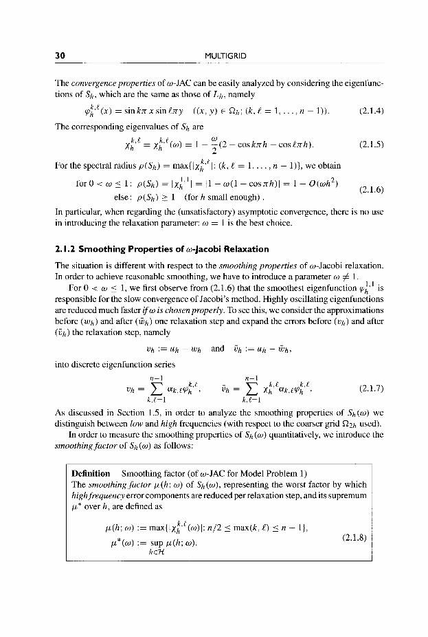
The convergence properties of w-JAC can be easily analyzed by considering the eigenfunc- tions of sh, which are the same as those of Lh, namely
(2.1.4) k L qh' (x) = s inknxs in lny ((x,y) E Gh; ( k , l = 1, .. . , n - 1)).
The corresponding eigenvalues of s h are w
(2.1.5) k ! = xh' (0) = 1 - -(2 - cosknh - c o s k h ) . 2
k e For the spectral radius p(Sh) = max{)xh' I: ( k , l = 1, . . . , n - l)}, we obtain 1,1 2 f o r O < w I l : p (sh)=Ixh I = I l - o ( 1 - C o S n h ) l = l - O ( w h )
(2.1.6)
In particular, when regarding the (unsatisfactory) asymptotic convergence, there is no use in introducing the relaxation parameter: w = 1 is the best choice.
else: p(&) 2 1 (for h small enough) .
2. I .2 Smoothing Properties of w-Jacobi Relaxation
The situation is different with respect to the smoothing properties of w-Jacobi relaxation. In order to achieve reasonable smoothing, we have to introduce a parameter w # 1.
For 0 < w i 1, we first observe from (2.1.6) that the smoothest eigenfunction q;" is responsible for the slow convergence of Jacobi's method. Highly oscillating eigenfunctions are reduced much faster i fw is chosen properly. To see this, we consider the approximations before (wh) and after (Wh) one relaxation step and expand the errors before (Vh) and after (Ch) the relaxation step, namely
Vh := Uh - Wh and ilh := U h - Wh,
into discrete eigenfunction series n-1 n-1
Vh = c @ , k , e q i ' e , i h = c X:"@,k,eqi". (2.1.7)
As discussed in Section 1.5, in order to analyze the smoothing properties of &(W) we distinguish between low and high frequencies (with respect to the coarser grid fi2h used).
In order to measure the smoothing properties of s h (w) quantitatively, we introduce the smoothingfuctor of s h (w) as follows:
k , t = l k,L=l
Definition The smoothing factor p(h ; w ) of s h (w), representing the worst factor by which highfrequency error components are reduced per relaxation step, and its supremum p* over h, are defined as
Smoothing factor (of w-JAC for Model Problem 1)
k l p(h ; w ) := max{lxh' (w) I : n/2 i max(k, l ) 5 n - l}, (2.1 .S)
P * ( W ) := sup p ( h ; 0). h&i

BASIC MULTlGRlD I 31
p(h; w ) = max 1 - -(2 - cosknh - coslnh) { I 1 : n / 2 5 max(k, l ) 5 n - 1
This shows that Jacobi’s relaxation has no smoothing properties for w 5 0 or w > 1
p(h; w ) ? 1 if w 5 0 or w > 1 (and h sufficiently small).
For 0 < w < 1, however, the smoothing factor is smaller than 1 and bounded away from 1, independently of h. For w = 1, we have a smoothing factor of 1 - O(h2) only. In particular, we find from (2.1.9) that
1 i f w = 1
315 ifw =4/5.
cos n h i f w = 1 (2 + cosnh)/4 if w = 1/2 p*(w) =
(1+2cosnh) /5 i f w = 4 / 5
(2.1. lo)
The choice w = 415 is optimal in the following sense:
inf { p * ( w ) : 0 5 w 5 l} = p*(4/5) = 315.
With respect to p(h; w ) , one obtains
3cosnh 3 inf {p(h; w ) : 0 5 w 5 1) = p = - - 10(h2)1.
This means that one step of w-JAC with w = 4/5 reduces all high frequency error compo- nents by at least a factor of 3/5 (independent of the grid size h).
The above consideration is a first example of what we call smoothing analysis.
2. I .3 Gauss-Seidel-type Iteration (Relaxation)
In Section 1.5.1 we introduced Gauss-Seidel iteration with a lexicographic ordering of the grid points. A different ordering is the so-called red-black ordering (see Fig. 1.7). If we use this red-black ordering for Gauss-Seidel iteration, we obtain the Gauss-Seidel red-black (GS-RB) method.

32 MULTlGRlD
Remark 2.1.1 The red-black ordering of grid points is also called odd-even ordering. This notation has the advantage that the two types of grid points are more clearly addressed (a grid point ( x i , y j ) is oddeven if i + j is odd/even) than with the term red-black. Since
>> red-black is more often used in the literature, we will stay with red-black.
The significance of using a relaxation parameter w in Gauss-Seidel iteration is well known in the classical Gauss-Seidel convergence theory. For Model Problem 1, lexico- graphic Gauss-Seidel with a relaxation parameter is described by
Zm+l 1 2 h ( x i , y j ) = s [ h fh(xi3 ~ j ) +u;+'(x i - h , y j > + u ~ ( x i + h , y j )
+ . ~ + l (xi 3 y j - h ) + .;I" (xi 3 y j + h ) ]
q. (2.1.1 1)
p + l h = u r + w ( z h m+ l -
The parameter w not only enters explicitly in (2.1.1 l), but also implicitly in the "new values" u;" (xi - h, y j ) and u;" ( x i , y j - h ) . We will call this algorithm w-GS-LEX in the following. The corresponding algorithm with red-black ordering of the grid points and relaxation parameter w is called w-GS-RB in this book.
We recall that, for Model Problem 1, the convergence of Gauss-Seidel iteration can be substantially improved by an overrelaxation parameter w*. With
we obtain 1 - sinnh 1 + sinnh
p(w*-GS) = w* - 1 = = 1 - O ( h )
instead of
~ ( G s ) = 1 - o ( h 2 ) (form = 1).
This is the classical result on successive overreluxution (SOR) [431]. Note that this result for Gauss-Seidel iteration is independent of the ordering of grid points.
Gauss-Seidel-type methods represent a particularly important class of smoothers. In the multigrid context the smoothing properties of Gauss-Seidel are much more important than the convergence properties. We will, however, not analyze the smoothing proper- ties of Gauss-Seidel-type relaxations, here. Since, different from the Jacobi situation, the eigenfunctions of Lh (2.1.4) are not eigenfunctions of the Gauss-Seidel operator, we need different tools for this analysis, which will be discussed in detail in Chapter 4. Here, we summarize the results of the smoothing analysis for Gauss-Seidel-type relaxations. For Model Problem 1, we obtain the smoothing factors
p(GS-LEX) = 0.50 p(GS-RB) = 0.25
(for w = l ) , (for w = 1).
(The factor of 0.25 for GS-RB is valid if only one or two smoothing steps are performed.) This result shows that the ordering of the grid points has an essential influence on the

BASIC MULTlGRlD I 33
smoothing properties in the case of Gauss-Seidel relaxations. On the other hand, for Model Problem 1, the introduction of a relaxation parameter does not improve the smoothing properties of GS-LEX relaxation essentially (see Section 4.3).
The situation is somewhat different for GS-RB, for which an overrelaxation parameter can improve the smoothing properties (see Section 2.9 and [427,428]).
2. I .4 Parallel Properties of Smoothers
Here, we compare the smoothing properties and the parallel features of w-JAC, GS-LEX and GS-RB. First, w-JAC is ‘:fully a h parallel”. By this we mean that the w-Jacobi opera- tor (2.1.3) can be applied to all grid points n h simultaneously; the new values do not depend on each other. We also say that the degree of parallelism (par-deg) is
par-deg(w-JAC) = # a h .
If we use GS-LEX instead, we have dependences since we want to use the most recent values of U h wherever possible. Grid points lying on a diagonal in a h (see Fig. 2.1) are independent of each other for five-point discretizations and can be treated in parallel. The degree of parallelism here clearly varies from one diagonal to the next and is restricted by
par-deg(GS-LEX) 5 (#ah)”*.
In case of GS-RB each step of the Gauss-Seidel relaxation consists of two half-steps. In the first half-step, all red grid points ( 0 ) are treated simultaneously and independently (see Fig. 2.2). In the second half-step, all black grid points ( 0 ) are treated, using the updated values in the red points. The degree of parallelism is
par-deg(GS-RB) = $#G?h.
Table 2.1 summarizes the properties of these relaxation schemes for Model Problem 1 : w-JAC is fully parallel, but unfortunately not a really good smoother (not even with an
Figure 2. I. Diagonal grid points such as the 0 (or the 0 ) can be treated in parallel in GS-LEX. Going from one diagonal to the next ( f l ) is sequential.

34 MULTlGRlD
Figure 2.2. Red-black distribution of grid points in ah.
Table 2. I. Smoothing factors for various relaxation schemes. The smoothing factors marked * will be obtained from the analysis in Sections 4.3 and 4.5; the factor marked t is only valid if a t most one or two smoothing steps are performed. (Here, N denotes the number of grid points #ah corresponding to the unknown grid values of uh.)
~
Relaxation Smoothing factor Smoothing Parallel degree
W-JAC, w = 1 1 No N Full W-JAC, w = 0.5 0.75 Unsatisfactory N Full W-JAC, w = 0.8 0.6 Acceptable N Full GS-LEX, w = 1 0.5* Good - < f i Squareroot GS-RB, w = 1 0.25*+ Very good ; N Half
optimized parameter w) whereas GS-LEX has reasonable smoothing properties but is not satisfactorily parallel. However, GS-RB is both a very good smoother (much better than w-JAC) and highly parallel.
2.2 INTRODUCING THE TWO-GRID CYCLE
As stated in Section 1.5, the basic multigrid consists of two ingredients: smoothing and coarse grid correction. We start with the two-grid cycle, the natural basis for any multigrid algorithm. For this purpose, we consider a discrete linear elliptic boundary value problem of the form
L h u h = f h ( a h ) (2.2.1)
and assume that Lh-l exists. As we are not going to give concrete quantitative results in this section, we do not make
precise assumptions about the discrete operator L h , the right-hand side f h or the grid 0th. For a simple but characteristic example, one may always think of Model Problem 1 or some more general Poisson-like equation.

BASIC MULTlGRlD I 35
U? + d r = fh - L h U r + i h 6 r = d p + u;” = U? + 6;
2.2. I Iteration by Approximate Solution of the Defect Equation
One way of introducing the two-grid idea is to start from a general iteration based on an approximate solution of the defect equation.
For any approximation u r of the solution U h of (2.2.1), we denote the error by
:= Uh - U r (2.2.2)
and the defect (or residual) by
. (2.2.9)
d r := f h - L h U r
Trivially, the defect equation
(2.2.3)
L ~ v ; = d r (2.2.4)
is equivalent to the original equation (2.2.1) since
We describe these steps by the following procedural formulation:
U r + d p = f h - L h U r --+ L h V r = d r --+ Uh = U r + V r . (2.2.6)
This procedure, however, is not a meaningful numerical rocess. However, if L h is approx- imated here by any “simpler” operator i h such that ii‘exists, the solution 6r of
Lhi$ = d r (2.2.7)
gives a new approximation
u;+1 := u r + 6F . (2.2.8)
The procedural formulation then looks like
I I
Mh = Ih - C h L h : G(%-z) + G ( f i h ) , (2.2.10)
where Ch := (ih)-’ and Ih denotes the identity on G(f&) . We have
(2.2.1 1) ,m+l = MhUr + Sh with Sh = ( L h ) - ’ f h (m = 0, 1 , 2 , . . .).

36 MULTlGRlD
For the errors, it follows that
and for the defects that
d;" = LhMhLi 'dr = (Zh - LhCh)dr (m = 0 , 1 , 2 , . . .). (2.2.13)
If we start the iteration with uo = 0, then we can represent u r (m = 1,2, . . . ) as
u r = (Zh + M h + Mh2 + ' ' ' + M f - l ) ( i h ) - ' f h
= (Zh - M?)(Zh - Mh)-'(ih)-lfh (2.2.14)
= (Zh - M F ) L i l f h .
For general remarks on iterations such as (2.2.1 l), we refer to the discussion in Section 1.6.1. The asymptotic convergence properties of the above iterative process are characterized by the spectral radius (asymptotic convergence factor) of the iteration operator, i.e.
If some norm 1 1 . 11 on G(C2h) is introduced,
give upper bounds for the error reduction factor and the defect reduction factor, respectively, for one iteration.
Remark 2.2.1 Classical iterative linear solvers such as Jacobi or Gauss-Seidel iterations if applied to (2.2.1) can be interpreted as (iterated) approximate solvers for the defect equation. For w-JAC we have, for example,
where Dh is the "diagonal" part of the matrix corresponding to L h . Similarly, GS-LEX is obtained by setting i h to be the "lower triangular" part of the matrix corresponding to Lh including its diagonal part. >>
Remark 2.2.2 (2.2.1 1) can be interpreted as iterated approximate solvers for the defect equation if
More generally, any of the classical iterative linear solvers of the form
is invertible. For then we can set i h := Ch-'. >>

BASIC MULTlGRlD I 37
2.2.2 Coarse Grid Correction
One idea to approximately solve the defect equation is to use an appropriate approximation L H of Lh on a coarser grid Q H , for instance the grid with mesh size H = 2h. This means that the defect equation (2.2.4) is replaced by
L H G ~ = d g . (2.2.17)
Here we assume
L H : G ( Q H ) + ~ ( Q H ) , dim G ( Q H ) < dim 6 ( Q h ) (2.2.18)
and L H - ~ to exist. As d z and GE are grid functions on the coarser grid QH, we assume two (linear) transfer operators
IF : G ( f i h ) + G ( Q H ) , I; G ( f i H ) + 6 ( Q h ) (2.2.19)
to be given. I: is used to restrict d p to Q H :
I dg := I F d p I (2.2.20)
and I ; is used to interpolate (orprolongate) the correction 6; to Qh:
(2.2.21) I I
The simplest example for a restriction operator is the "injection" operator
d H ( P ) = I F d h ( P ) := d h ( P ) for P E QH C a h , (2.2.22)
which identifies grid functions at coarse grid points with the corresponding grid functions at fine grid points. A fine and a coarse grid with the injection operator are presented in Fig. 2.3.
Altogether, one coarse grid correction step (calculating .;I"" from u p ) proceeds as follows.
Coarse grid correction u p + u;I""
- Compute the defect
- Restrict the defect (fine-to-coarse transfer) d H - h h
d r = f h - LhUr m - I H d m
- Solve on Q H
- Interpolate the correction (coarse-to-fine transfer) LHGE = d g
GP = I; fiz - Compute a new approximation h = uh rn +GP

38 MULTIGRID
Figure 2.3. A fine and a coarse grid with the injection operator.
The associated iteration operator is given by -1 H
Ih - Ch L h with Ch = I k L H zh
However:
(2.2.23)
Remark 2.2.3 Taken on its own, the coarse grid correction process is of no use. It is not convergent! We have
p ( I h - 1; L i ' z F L h ) 3 1. (2.2.24)
>>
This remark follows directly from the fact that I F maps G ( Q h ) into the lower dimensional space ~ ( Q H ) and therefore c h = I ; LGlZF is not invertible. This implies that
Ch L h vh = 0 for certain Vh # 0.
Example 2.2.1 It may be illustrative to see what ChLhVh = 0 means in practice. For the simple injection operator (2.2.22), for example, any error function Vh E G ( Q h ) with
for P E S ~ H for P @ S ~ H
is annihilated by ZF and therefore by c h . Such an error function Vh will thus not be changed by a pure coarse grid correction.

BASIC MULTlGRlD I 39
As a more concrete example, consider Model Problem 1 ( L h = - A h ) , h = l / n , and
n n 2 2
Vh(X, y ) = sin -nx sin - n y . (2.2.25)
For standard coarsening, we find
2h V h ( P ) = L h V h ( P ) = l h L h V h ( P ) = 0 forall P E ! & J h .
(This relation holds for any restriction operator I l h as long as the stencil of I l h is symmetric in x and y.) Clearly, V h belongs to the high frequency part of the eigenfunctions of L h .
A
2.2.3 Structure of the Two-grid Operator
The above considerations imply that it is necessaq to combine the two processes of smooth- ing and of coarse grid correction.
Each iteration step (cycle) of a two-grid method consists of a presmoothing, a course grid correction and a postsmoothing part. One step of such an iterative two-grid method (calculating u;" from u?) proceeds as follows:
Two-grid cycle u ~ + ' = TGCYC(U?, L h , f h , u1, u2)
(1) Presmoothing - Compute i? by applying ul (L 0) steps of a given smoothing procedure
to u;:
i? = SMOOTHu1 (U;, L h , f h ) . (2.2.26)
(2) Coarse grid correction (CGC) - Compute the defect d r = f h - L h i ? .
-m - I H d m . d H - h h - Restrict the defect
- Solve on C ~ H LH.~ ' ; = d z . (2.2.27)
- Interpolate the correction (coarse-to-fine transfer)
approximation
(fine-to-coarse transfer) -
p - I h Gm h - H H '
m , after CGC - Compute the corrected ' h = i; + ijp,
( 3 ) Postsmoothing - Compute u;" by applying u2 (> 0) steps of the given smoothing
rn,after CGC. procedure to u
Um+l h - - SMOOTHV2(um,after h CGC 9 L h , f h ) . (2.2.28)

40 MULTIGRID
M h - - h S V 2 K H S V ‘ h h with K f := Ih - I i L L ’ I F L h
SMOOTH”*
. (2.2.29)
Figure 2.4. Structure of a two-grid cycle.
For the formal description of smoothing procedures we have used the notation
i r = SMOOTH’(U?, Lh, f j ) .
With this notation we combine the advantages of a more mathematically oriented operator- like notation and a more computer science oriented formal procedural notation. In particular, the number u of smoothing steps appears as an upper (power) index. Similar notation is also used for the two-grid and for the multigrid procedure.
The two-grid cycle is illustrated in Fig. 2.4. From the above description, one immediately obtains the iteration operator M f of the
(h , H ) two-grid cycle:
0 the smoothing procedure SMOOTH ( u r , Lh, f j ) ,
0 the numbers u1, u2 of smoothing steps, 0 the coarse grid C ~ H , 0 the fine-to-coarse restriction operator I F , 0 the coarse grid operator L H , 0 the coarse-to-fine interpolation operator I ; .
Experience with multigrid methods (and multigrid theory) shows that the choice of these components may have a strong influence on the efficiency of the resulting algorithm. On the other hand, there are no general simple rules on how to choose the individual components in order to construct optimal algorithms for complicated applications. One can, however, recommend certain choices for certain situations. The main objective of the elementary multigrid theory (see Chapter 3 ) and the local Fourier analysis (see Chapter 4) is to analyze the convergence properties of multigrid theoretically and to provide tools for the proper choice of multigrid components.

BASIC MULTlGRlD I 41
2.3 MULTlGRlD COMPONENTS
In this section, we will introduce and list some important examples of how some of the multigrid components can be specified.
The idea of giving these specifications is to make our presentation more concrete and to introduce corresponding notations. The multigrid components specified here are needed in Section 2.5.1, where a specific multigrid Poisson solver is introduced. Therefore, readers who are more interested in the general structure of multigrid than in specific details may skip this section for the time being.
2.3. I Choices of Coarse Grids
In this subsection, we will mtntion some possible and common choices for the grid Q H . The simplest and most frequently used choice is standard coarsening, doubling the mesh size h in every direction. Most of the results and considerations in this book refer to this choice. In d dimensions, the relation between the number of grid points (neglecting boundary effects) is
We speak of semicoarsening in 2D if the mesh size h is doubled in one direction only, i.e. H = (2h,, hy) (x-semicoarsening, see Fig. 2.5) or H = (h,, 2hy) (y-semicoarsening). This is especially of interest for anisotropic operators (see Section 5.1). Note that in this case
# Q H % i # Q h . (2.3.1)
In 3D, we have additional types of semicoarsening: we can double the mesh size in one
We speak of red-black coarsening if the coarse grid points are distributed in the fine
Also other coarsenings, like 4h-coarsening, are sometimes of interest. We mention that in the context of the AMG approach (see Appendix A), the coarse grid
Q H is not formed according to such a fixed simple strategy. Using the algebraic relations in the corresponding matrix, Q H is determined by the AMG process itself in the course of calculation. We will see that the red-black coarsened grid is a standard choice for Model Problem 1 in AMG.
or in two directions (see Section 5.2).
grid in a red-black (checkerboard) manner (see Fig. 2.5).
Figure 2.5. Examples of standard; x-semi-; red-black; (h, 4h)-coarsening in a square computational domain 52. The grid points of 52" are marked by dots.

42 MULTlGRlD
2.3.2 Choice of the Coarse Grid Operator
So far, we have not described precisely how the coarse grid operator L H can be chosen. A natural choice is to use the direct analog of Lh on the grid Q H . For Model Problem 1, this means
L H = & [-I 4 -81 .
The direct coarse grid analog of the fine grid operator Lh will be used in most parts of this book, in particular in all chapters on basic multigrid.
There are, however, applications and multigrid algorithms, which make use of a different approach. The so-called Galerkin coarse grid operator is dejined by
0 -1
0 -1 H
(2.3.2)
where I F and 1; are appropriate transfer operators. We will return to the Galerkin approach in the context of problems with discontinuous coefficients in Chapter 7 and in Appendix A, where algebraic systems of equations without a grid-oriented background will be treated.
2.3.3 Transfer Operators: Restriction
The choice of restriction and interpolation operators I F and I ; , for the intergrid transfer of grid functions, is closely related to the choice of the coarse grid. Here, we introduce transfer operators for standard coarsening (see Fig. 2.5), i.e. the grid transfers between the grid a h and the 2h-grid Q2h.
A restriction operator I f h maps h-grid functions to 2h-grid functions. One restric- tion operator already discussed is the injection operator (2.2.22). Another frequently used restriction operator is the full weighting (FW) operator, which in stencil notation reads
(2.3.3)
Applying this operator to a grid function dh (x, y) at a coarse grid point (x, y) E Q2h
means
Obviously, a nine-point weighted average of dh is obtained.

BASIC MULTlGRlD I 43
I&C2h(X, y ) =
Remark 2.3.1 The F W operator can be derived from a discrete version of the condition
’ 62h ( X , Y) for
for 0 for 0 (2.3.7)
1
i [ 6 2 h ( X + h , y) + C2h(X - h , y)1
2 [ 6 2 h ( X 2 y + h ) + 6 2 h ( X , y - h)l
i [ C * h ( X + h, y + h ) + G 2 h b + h , y - h )
, +G2h(x - h , y + h ) + 62h(x - h , y - h ) ] for 0.
(2.3.5)
for = [x - h, x +h] x [ y - h, y +h] where the midpoint rule is used to approximate the integral on the right-hand side of the equation and the trapezoidal rule is used to approximate
>> the integral on the left-hand side.
Remark 2.3.2 The FW operator in d dimensions can also be constructed as a tensor product of the one-dimensional F W operators
L A
These 1D restriction operators are of particular interest in combination with the semicoars- ening approach discussed in the previous section. They are also commonly used in case of
>> nonelimirzated boundary conditions (see Section 5.6.2).
A third restriction operator is halfweighting (HW):
(2.3.6)
Remark 2.3.3 Linear interpolation in d dimensions can easily be constructed by arecursive procedure (over the d dimensions) of 1 D linear interpolations. Also d-dimensional higher order interpolations can be constructed and programmed very efficiently in this way.
>>

44 MULTlGRlD
Figure 2.6. A fine grid with symbols indicating the bilinear interpolation (2.3.7) used for the transfer from the coarse grid ( 0 ) .
'/* ( ' I 2 (
0
0
0 0 0
' / 2
'I*
Figure 2.7. The distribution process for the bilinear interpolation operator. , Gz,, grid; 0, 0 and 0 as in (2.3.7) and in Fig. 2.6.
In stencil notation we write the bilinear interpolation operator Ith (2.3.7) as . ; = ; I 2 1 2 1 h 4 ? [
1 2 1 2 h
(2.3.8)
In this notation, the stencil entries correspond to weights in a distribution process as illus- trated in Fig. 2.7. Therefore, the brackets are reversed.

BASIC MULTlGRlD I 45
For more general interpolation operators the stencils read
t-1,1 f0,l t1 , I . ' . . t-1,o t0,o t1.0 . . . . f-l.-l to.-1 f l , - l . .
. .
h
(2.3.9)
2h
Again, only a finite number of coefficients tK, ,K2 is assumed to be nonzero. The meaning of this stencil terminology is that coarse grid values are distributed to the fine grid and the weights in this distribution process are the factors tK1 , K 2 .
Remark 2.3.4 The formulas for linear interpolation of corrections can be applied near Dirichlet boundaries even if the boundary conditions have been eliminated. The corrections
>> from a boundary point are assumed to be 0 in this case.
2.4 THE MULTlGRlD CYCLE
In Section 2.2 we have described the multigrid principle only in its two-grid version. In the multigrid context, two-grid methods are of little practical significance (due to the still large complexity of the coarse grid problem). However, they serve as the basis for the multigrid method.
Remark 2.4.1 Methods involving only two grids (or a fixed, small, number of grids) are of some interest in other frameworks, e.g. in the context of certain domain decomposition and related methods [362]. >>
From two-grid to multigrid The multigrid idea starts from the observation that in a well converged two-grid method it is neither useful nor necessary to solve the coarse grid defect equation (2.2.27) exactly. Instead, without essential loss of convergence speed, one may replace 6; by a suitable approximation. A natural way to obtain such an approximation is to apply the two-grid idea to (2.2.27) again, now employing an even coarser grid than i 2 ~ .
This is possible, as obviously the coarse grid equation (2.2.27) is of the same form as the original equation (2.2.1). If the convergence factor of the two-grid method is small enough, it is sufficient to perform only a few, say y , two-grid iteration steps (see Fig. 2.8) to obtain a good enough approximation to the solution of (2.2.27). This idea can, in a straight- forward manner, be applied recursively, using coarser and coarser grids, down to some coarsest grid.

46 MULTlGRlD
Two-grid method: Three-grid methods:
v v w w y = l y = 2 y = 3
Four-grid methods:
y = l y = 2
A five-grid method:
y = 2
Figure 2.8. Structure of one multigrid cycle for different numbers of grids and different values of the cycle index y ( 0 , smoothing; 0, exact solution; \, fine-to-coarse; /, coarse-to-fine transfer).
On this coarsest grid any solution method may be used (e.g. a direct method or some relaxation-type method if it has sufficiently good convergence properties on that coarsest grid). In ideal cases, the coarsest grid consists of just one grid point.
2.4. I Sequences of Grids and Operators
Figure 2.8 illustrates the structure of one iteration step (cycle) of a multigrid method with a few pictures. Usually, the cases y = 1 and y = 2 are particularly interesting.
For obvious reasons, we refer to the case y = 1 as V-cycles and to y = 2 as W-cycles. The number y is also called cycle index.
2.4.2 Recursive Definition
For a formal description of multigrid methods we now use a sequence of coarser and coarser grids Q h k , characterized by a sequence of mesh sizes hk:
BASIC MULTlGRlD I 47
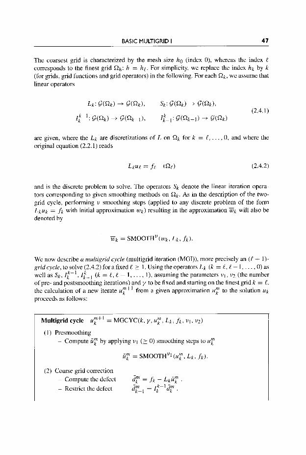
The coarsest grid is characterized by the mesh size ho (index 0), whereas the index e corresponds to the finest grid f i h : h = he. For simplicity, we replace the index h k by k (for grids, grid functions and grid operators) in the following. For each f i k , we assume that linear operators
are given, where the L k are discretizations of L on Qk for k = l , . . . , 0, and where the original equation (2.2.1) reads
Leue = ft ( f ie) (2.4.2)
and is the discrete problem to solve. The operators sk denote the linear iteration opera- tors corresponding to given smoothing methods on Q k . As in the description of the two- grid cycle, performing u smoothing steps (applied to any discrete problem of the form L k u k = f k with initial approximation W k ) resulting in the approximation w k will also be denoted by
We now describe a multigrid cycle (multigrid iteration (MGI)), more precisely an (t + 1)- grid cycle, to solve (2.4.2) for a fixed l > 1 . Using the operators L k (k = l, t - 1 , . . . , 0) as well as s k , I [ - ' , ( k = e, e - 1, . . . , I), assuming the parameters u1, u2 (the number of pre- and postsmoothing iterations) and y to be fixed and starting on the finest grid k = l, the calculation of a new iterate u:" from a given approximation .;I" to the solution U k proceeds as follows:
Multigrid cycle u:" = MGCYC(k, y , u;I", L k , f k , u i , u2)
(1) Presmoothing - Compute .;I" by applying ul (> 0) smoothing steps to .;I"
.;I" = SMOOTHu1 ( U r , L k , f k ) .
(2) Coarse grid correction - Compute the defect - Restrict the defect
d r = f k - L k . 7 . drpI = 1;--1q.

48 MULTlGRlD
- Compute an approximate solution ijkm_ of the defect equation on Qk- 1
- (2.4.3) Am m Lk-l V k - 1 = d k - l
by
If k = 1, use a direct or fast iterative solver for (2.4.3). If k > 1, solve (2.4.3) approximately by performing y(' 1) k-grid cycles using the zero grid function as a first approximation
-m uk-1 = MGcYc'(k - 1, y , 0, Lk-1, dF-1, v1, v2). (2.4.4)
Interpolate the correction i'p = I:- 6km_ . Compute the corrected
m,afterCGC = u;z" + 6 ~ . approximation on ok ' k
(3) Postsmoothing - Compute u;+l by applying v2 (3 0) smoothing steps to u:, after CGC:
In (2.4.4) the parameter y appears twice: once (as an argument of multigrid cycle (MGCYC)) for the indication of the cycle type to be employed on coarser levels and once (as a power) to specify the number of cycles to be carried out on the current coarse grid level.
Remark 2.4.2 Since on coarse grids we deal with corrections to the fine grid approxima- >> tion, this multigrid scheme is also called the correction scheme (CS).
Let k f k denote the iteration operator of the multigrid method described in the previous algorithm.
Theorem 2.4.1 The multigrid iteration operator Me is given by the following recursion:
An explicit proof of (2.4.5) can easily be given by means of induction on k . Implicitly, a proof is also contained in the following remark.

BASIC MULTlGRlD I 49
Remark 2.4.3 The difference between the ( h k , h k - 1 ) two-grid iteration operator
(2.4.6) Mi- ' = s p ( z k - z k - i ( L k - 1 ) k - I k 1 L k ) s i ' ,
and the above multigrid iteration operator Mk is obviously that
( ~ k - l ) - l is replaced by (1k-1 - ( k f k - l ) y ) ( L k - l ) - l . (2.4.7)
This reflects the fact that the coarse grid equation (2.4.3) is solved approximately by y multi- grid steps on the grid f i k - 1 starting with zero initial approximation (compare with (2.2.14)).
>> Thus, (2.4.5) follows immediately from (2.2.14).
Remark 2.4.4 (F-cycle) It is convenient, but not necessary, that the parameters U I , u2 and the cycle index y are fixed numbers. In particular, y = y k may depend on k . Certain combinations of y = 1 and y = 2 are indeed used in practice. We mention here only the so-called F-cycle [66] which is illustrated in Fig. 2.9. The corresponding iteration operator M: is recursively defined by MF = M I (as in (2.4.5)) and
hf; = s F ( l k - Ik-1(1&1 k - Mk-lM&l)(Lk-I)-lz~-lLk)SkV' V
( k = 2 , . . . , t ) .
Here MJPl is the corresponding V-cycle iteration operator (i.e. (2.4.5) with y = 1 and k - 1 instead of k) . >>
Remark 2.4.5 In selfcontrolling algorithms as proposed in [59, 641, variable cycles are used. Switching from one grid to another (to a finer or a coarser one) is controlled by suitable accommodative criteria.
I = 1 1 = 2
1 = 4
7 't
1 = 3
f
t /
VV k
>>
Figure 2.9. Structure of an F-cycle.

50 MULTlGRlD
for y = 1 for y = 2 for y = 3 for y = 4
We 1 O ( N l log“)
2.4.3 Computational Work
In Section 2.5.2 and Chapter 3, we will see that we can achieve a multigrid convergence factor that is independent of the mesh size: The convergence speed does not depend on the size of the$nest grid. But the fact that a certain method has an h-independent convergence factor says nothing about its efficiency as long as the computational work is not taken into account. In the following, we will estimate the computational work of a multigrid method.
From the recursive definition of a multigrid cycle as given in Theorem 2.4.1 it imme- diately follows that the computational work We per multigrid cycle on C2l is recursively given by
(2.4.8)
Here W l + l denotes the computational work of one (hk+l , hk) two-grid cycle excluding the work needed to solve the defect equations on !&, and WO denotes the work needed to compute the exact solution on the coarsest grid C2o. By “computational work”, we always denote some reasonable measure, typically the number of arithmetic operations needed. If y is independent of k , we obtain from (2.4.8)
k w1 = wp + WO, wk+l = Wk+, + ykwk (k = 1, . . . , e - I).
’
(2.4.9)
Let us first discuss the case of standardcoarsening in 2D with y independent of k . Obviously,
Nk = 4Nk-1 (k = 1 , 2 , . . . , e ) (2.4.10)
where Nk = #Qk (number of grid points on !&) and “=” means equality up to lower order terms (boundary effects). Furthermore, we assume that the multigrid components (relaxation, computation of defects, fine-to-coarse and coarse-to-fine transfer) require a number of arithmetic operations per point of the respective grids which is bounded by a small constant C , independent of k :
WL-l 1 c’vk (k = I , 2 , . . . , e ) . (2.4.1 1)
(As above, “1” means ‘‘I” up to lower order terms.) Under these assumptions, one obtains the following estimate for the total computational
work Wt of one complete multigrid cycle in 2 0 from (2.4.9), together with (2.4.10) and (2.4.1 1) :
(2.4.12)
For y = 4 the total computational work on each level is essentially constant (up to lower order terms) and the number of grid levels is O(log Ne).

BASIC MULTlGRlD I 51
Summary This estimate of Wt shows that the number of arithmetic operations needed for one 2D multigrid cycle is proportional to the number of grid points of the finest grid for y 5 3 and standard coarsening (under quite natural assump- tions which are satisfied for reasonable multigrid methods). Together with the h-independent convergence, this means that multigrid methods achieve a fixed reduction (independent of h ) of the error in O ( N ) operations. The constant of proportionality depends on the type of the cycle, i.e. on y , the type of coarsening and the other multigrid components. For reasonable choices of these components, the constants of proportionality are small.
Remark 2.4.6 In practice, it is not necessary to choose a grid consisting of only one interior point as the coarsest grid. Instead, it is sufficient to choose the coarsest grid WO such that the amount of work (of the corresponding solution method) on WO is negligible.
>>
Remark 2.4.7 Wi-' in (2.4.8) or, in other words, the constant C in (2.4.1 1) is determined by the computational work needed for the individual multigrid components of the (hk , hk- 1 ) two-grid method, namely
wi-11 - (UWo + wl 4- wz)Nk. (2.4.13)
Here v = u1 + u2 is the number of smoothing steps used, W O , wl and w2 are measures for the computational work per grid point of f i k needed for the single components, namely
- wo: one smoothing step on Q k ,
- w1: computation of the defect and its transfer to Qk-1, - w2: interpolation of the correction to Qk and its addition to the previous approximation.
>>
More generally, in particular for other than standard coarsening, we can assume
In that case we obtain for y independent of k
r / ( t - y ) C N t O ( N t log N t )
for y < r for y = r ,
wt = (2.4.14)
generalizing (2.4.12), where r = 4. If we consider, for example, red-black coarsening or semicoarsening (see Fig. 2.5), we have t = 2. In this case, we already see that W-cycles do not yield an asymptotically optimal multigrid method: for r = 2 and fixed y , only y = 1 yields a cycle for which Wt is proportional to N t .

52 MU LTI G R I D
Remark 2.4.8 The computational work WF of an F-cycle as introduced in Remark 2.4.4 in combination with standard coarsening is also O(") since this cycle is more expensive than the V-cycle and less expensive than the W-cycle. In particular, we obtain
and thus
Remark 2.4.9 For 2D semicoarsening (t = 2) we find that the computational work of an F-cycle still is of the form O(Ng) . This can be seen if we take into account that a grid Qk is processed once more often than grid Qk+l (see Fig. 2.9). Correspondingly, if Wi-' is the amount of work spent on the finest grid, then the asymptotical amount of work (for l + 00) of the F-cycle in case of semicoarsening is
>>
So far, we have estimated and discussed the computational work of multigrid cycles. In order to assess the numerical efficiency of such an iterative multigrid solver precisely, it is necessary to take into account both its convergence behavior and the computational effort per iteration step (cycle). For example, in order to decide how many relaxation steps v = vl + v2 are appropriate per cycle and whether a V-, F- or W-cycle should be used, the effect of this decision on both the convergence speed and the computational work have to be analyzed. We will discuss these efficiency questions in the following section for a specific multigrid Poisson solver.
2.5 MULTlGRlD CONVERGENCE A N D EFFICIENCY
In this section we introduce the first specific multigrid algorithm. For that purpose we return to Model Problem 1, the discrete Poisson equation with Dirichlet boundary conditions in the 2D unit square. The algorithm presented here is a highly efficient Poisson solver. Its most characteristic multigrid component is the GS-RB relaxation for smoothing. We call it the red-black multigrid Poisson solver (RBMPS). In addition to its numerical efficiency, the algorithm is also highly parallel.
2.5. I An Efficient 2D Multigrid Poisson Solver
The algorithm is characterized by the following multigrid components. In this characteri- zation certain parameters and components still have to be specified:

BASIC MULTlGRlD I 53
- smoother: GS-RB relaxation as presented in Section 2. I , - restriction I:-': full weighting (2.3.4) (or half weighting (2.3.6), see Remark 2.5.1), - prolongation - standard coarsening: hk+l = hk/2, - size of coarsest grid: ho = 112.
: bilinear interpolation (2.3.7),
Remark 2.5.1 This version of the red-black multigrid Poisson solver is a particularly simple one. There are further variants of this algorithm, some of which are even more efficient [3 19, 3781, but less generally applicable. For example, the restriction operator FW can be replaced by HW (2.3.6) which is more efficient for certain choices of u ( u 3 3, see
>> Table 2.4 and Section 3.3.1).
In the following we want to discuss the influence of the number of relaxations u = ul +u2 and the cycle type (V, F, W) on the convergence speed of the algorithm and consequently the numerical eficiency of the algorithm.
We use the notation V(u1, uz) , F(u1, u2) or W(u1, u2) to indicate the cycle type and the number of pre- and postsmoothing steps employed. The finest grid is h = 11256. Furthermore, we can compare theoretical convergence results (which we will obtain in Chapter 3) with the measured convergence results. In Fig. 2.10 the multigrid convergence of the V(0,l)-cycle (meaning 0 pre- and 1 postsmoothing), of the V(1,l)-, the W(0,l)- and
0 le-08 i I X i i i
iteration 0 5 10 ' 5 . 20 25 30
Figure 2.10. The convergence history of different RBMPS cycles for Model Problem I .

54 MU LTI G R I D
the W(1,l)-cycle is presented, using FW as the restriction operator. The 12 norm of the defect is plotted in a log scale along the y-axis. The x-axis shows the number of multigrid iterations. (The results obtained by the F-cycle and by the W-cycle are nearly identical.)
From Fig. 2.10, we observe rapid convergence of multigrid, especially for the V( 1,l)- and W( 1 ,l)-cycles: they reduce the defect by a factor of within 12 multigrid iterations. Also the benefits of processing the coarse grid levels more frequently can be seen: the W-cycle (and the F-cycle) shows a better convergence than the V-cycle.
Remark 2.5.2 In practice, it is usually not necessary to reduce the defect by a factor of Convergence to discretization accuracy O ( h 2 ) (see the discussion in Section 2.6) is
sufficient in most cases, and is obtained much faster. Here, we reduce the defect further in >> order to illustrate the asymptotic convergence of the multigrid cycle.
2.5.2 How to Measure the Multigrid Convergence Factor in Practice
In order to construct, evaluate and analyze a multigrid iteration one often wants to determine its convergence factor p empirically (by measurement). In general, the only quantities that are available for the determination of p are the defects dh" (m = 1, 2, . . . ). We can measure, for example,
(2.5.1)
or
in some appropriate norm, say the discrete 1 1 . I I 2 norm (see Section 1.3.3). The quantity <(m) represents an average defect reduction factor over m iterations. For "sufficiently general" d: # 0 we have G ( m ) + p. i(m) is a good estimate for p if m is sufficiently large. In many cases the convergence history is also of interest. This can probably be best represented by graphics as in Fig. 2.10 or by a table of the values of q(').
Often the first few iteration steps do not reflect the asymptotic convergence behavior of the multigrid iteration. Then one may redefine i(m) as i(m) = ' ' ' - ' ' / ~ with a small number mg, typically between 2 and 5.
In Table 2.2 we present the values of q(m) and 4cm) from the convergence for Model Problem 1 in Fig. 2.10 for the cycles considered.
Remark 2.5.3 When performing too many cycles, machine accuracy might limit the measurements substantially. In order to be able to perform sufficiently many iteration steps to see the asymptotic convergence behavior, it is advisable to consider the homogeneous problem ( f = 0) with discrete solution uh = 0 and to start with an initial guess uo that is sufficiently large and general. In the case of our example, we then find asymptotic

BASIC MULTlGRlD I 55
Table 2.2. The quantities 4(m) and t (m) as a mea- sure for the convergence of the RBMPS (with FW) for Model Problem I (mo = 0).
V(0,l): q'26' = 0.343 4(26) = 0.333 V(1,I): q"2' = 0.101 4"') = 0.089 W(0,l): 4"" = 0.243 t(21) = 0.238 W(1,l): 4"" = 0.063 G ( " ) = 0.060
Table 2.3. Measured convergence factors of the RBMPS (with FW) for Model Problem I on grids of different mesh size. In each case the coarsest grid has a mesh size of ho = 1/2.
Cycle h = 1/512 h = 1/256 h = 1/128 h = 1/64 h = 1/32 h = 1/16
V(1,l): 0.10 0.10 0.10 0.10 0.1 1 0.12 F( 1,l): 0.063 0.063 0.063 0.063 0.063 0.067 W( 1 , l) : 0.063 0.063 0.063 0.063 0.063 0.067
convergence factors of 0.25 for the F(0,I)- or W(0,l)-cycle and of 0.074 for the F( 1,l)- or >> W( 1 ,l)-cycle after a large number of multigrid iterations.
h-independent convergence of multigrid The numerically measured conver- gence of the RBMPS is essentially independent of the size of the finest grid in the multigrid cycle. This behavior is demonstrated by the results in Table 2.3. In Chapter 3, we will see that this behavior is also confirmed by multigrid theory.
2.5.3 Numerical Efficiency
In order to choose the most efficient multigrid solver, it is necessary to look at both, its convergence speed and its costs. In practice, the time needed to solve the problem is the most interesting quantity. Table 2.4 shows the wall clock times for different multigrid (cycle) iterations. The iterations stopped after the initial defects had been reduced by a factor of
Table 2.4 throws a somewhat different light on the convergence results obtained before. The V(2,1)-cycle with HW is most efficient with respect to the wall clock time on the 256* grid. Since W- and F-cycles have the same convergence speed for this model problem, the W-cycle clearly is less efficient than the F-cycle here.
The times were measured on a single workstation.
Remark 2.5.4 Table 2.4 shows that it does not pay to use large values for u l and u2. This is a general observation. Though the convergence factors become (somewhat) better if the number of smoothing steps is increased, it is more efficient not to smooth the error too much but rather carry out a few more multigrid cycles. In practice, common choices are u = ul + u2 I 3. This observation can also be
>> verified theoretically (see Section 3.3.1).

56 MULTlGRlD
Table 2.4. Wall clock times and number of iterations for a defect reduction of a factor of lo-'' for different cycles and different restriction operators for Model Problem I on a 256' grid.
Fw HW c
Cycle Iterations Time (msec) Iterations Time (msec)
V(0,l): 26 1290 I67 7310 V(1,l): 12 759 13 740 V(2,l): 10 759 9 V(2,2): 9 799 8 669 F(0,l): 20 1270 34 1910 F(1, I): 10 819 10 740 F(2,l): 9 890 9 829 F(2,2): 8 930 8 880 W(0,l): 20 2269 34 3780 W(1,l): 10 1379 10 1379 W(2,l): 9 1450 9 1479 W(2,2): 8 1469 8 1460
Remark 2.5.5 Although the V-cycle is obviously the most efficient one for Model Problem 1, we will see later that F- or W-cycles may be superior for more complicated applications. >>
2.6 FULL MULTlGRlD
An initial approximation for iterative solvers, like multigrid, can be obtained by nested iteration. The general idea of nested iteration is to provide an initial approximation on a grid Q by the computation and interpolation of approximations on coarser grids. Within an arbitrary iterative process for the solution of a given discrete problem, this principle simply means that a lower (coarser) discretization level is used in order to provide a good initial approximation for the iteration on the next higher (finer) discretization level [226, 2271.
The efficiency of iterative multigrid (MGI) can be improved if it is properly combined with the nested iteration idea. This combination is called thefull multigrid (FMG) technique [58] . Typically, the FMG scheme is the most efficient multigrid version.
FMG has two fundamental properties:
(1) An approximation u:MG of the discrete solution U h can be computed up to an error I I U h - u ! ~ ~ I I which is approximately equal to the discretization error ~ ~ U - u h ~ ~ .
(2) FMG is an asymptotically optimal method, i.e the number of arithmetic oper- ations required to compute uEMG, is proportional to the number of grid points of (with only a small constant of proportionality).

BASIC MULTlGRlD I 57
The first property is explained in the following remark.
Remark 2.6.1 Since the discrete solution uh approximates the continuous solution u of the PDE only up to discretization accuracy, in many cases it does not make much sense to solve the discrete problem (1.3.2) exactly. We have to live with the discretization error I Iu - U h I I anyway. That is why it is usually sufficient to compute an approximation uEMG only up to discretization accuracy. By this we mean that
Huh - .;MGII = IIU - Uhll. (2.6.1)
More concretely we will derive estimates of the form
lluh - u;MGII I Bllu - uhll (2.6.2)
in Section 3.2.2, which immediately implies
(2.6.3)
We regard /I 1 as a sufficiently good value. In that case, “up to discretization accuracy” would mean that we allow a factor of 2 in comparing I Iu - u;MG I I with the discretization error. If necessary, much smaller values of /I can also be achieved.
Generally, it is not worth investing more work in a more accurate approximation of uEMG than suggested here because it is more cost-effective to refine the grid once more than to solve the present problem more accurately. It should be kept in mind that the final goal is usually a good approximation to the differential problem, not an extremely good
>> solution to the discrete problem.
At this point, we add a remark, which refers to a question multigrid beginners sometimes have.
Remark 2.6.2 In general, it is not sufficient to start the solution process on a very coarse grid, interpolate the approximation of the coarse grid solution to the next finer grid, smooth the visible error components and so on until the finest grid is reached. Actually, the interpo- lation of the approximation leads to nonnegligible high and low frequency error components on the fine grid (see Section 7.3 in [66] for a heuristic explanation) that can efficiently be reduced only by a subsequent smoothing of the error on all grid levels, i.e. by revisiting the
>> coarse levels in multigrid cycles.
2.6. I Structure of Full Multigrid
As in Section 2.4, we consider (2.4.2), i.e. a sequence of discrete approximations to (2.2.1). As in Section 2.4.2, we use the notation
MGCYC‘(k + 1, Y, wk, Lk, f k , u i , v2) : G(Qk) + G(ak) (2.6.4)
for a procedure consisting of r steps of a suitable iterative ( k + 1)-grid cycle with cycle index y for solving (2.4.2) with initial approximation W k (using grids Q k , . . . , Qo). The

58 MULTlGRlD
= FMG interpolation //
Figure 2. I I. Structure of FMG with r = 1 and y = 1 when using I = 4 (i.e. five grid levels).
right-hand sides f k on f i k can be defined recursively by fk = I t + , fk+l with f e = f In, or simply by f k = f lak . The objective is to achieve discretization accuracy on each level within a few (typically r = 1 or r = 2) multigrid cycles. (In general r may depend on k.) The structure of FMG (with Y = 1 and y = 1) is illustrated in Fig. 2.11.
which is applied to cor- rections, the FMG interpolation nf-l from Qk-1 to f i k transfers approximations of the solution to the fine grid. Moreover, the operator I I i - l represents an interpolation proce- dure which usually is of higher accuracy than the interpolation used within the multigrid iteration.
In contrast to the interpolation in the multigrid cycle
The FMG algorithm proceeds as follows:
Full multigrid For k = 0:
Solve Lou0 = fo, providing u ! ~ ~ = uo.
F o r k = 1,2, . . . , t : 24; := n;-luk-l FMG
uFMG = MGCYC'(k + 1 , y , U ! , Lk, f k , u1, v2).
Here, u p G denotes the resulting FMG approximation on grid a ! . In Section 3.2.2 we will see that FMG will deliver an approximation up to discretiza-
tion accuracy if the multigrid cycle converges satisfactorily and if the order of the FMG interpolation is larger than the discretization order of Le. A common FMG interpolation for second-order accurate discretizations is cubic (multipolynomial) interpolation. Cheaper interpolations especially suited for Model Problem 1 can also be constructed [378].
Example 2.6.1 Often, bicubic interpolation is an appropriate FMG interpolation. If, for instance, (x - 3h, y ) , (x - h , y ) , (x + h , y ) and (x + 3h, y ) are points on the coarse grid, where an approximation W2h is known, cubic interpolation can be used to compute an

BASIC MULTlGRlD I 59
approximation W h ( X , y ) at the fine grid point (x, y ) :
Cubic interpolation in the y-direction is analogous. Near the boundary, appropriate modi- fications can be used. A
2.6.2 Computational Work
The computational work WFMG needed for the FMG method can easily be estimated. By arguments similar to those in Section 2.4.3, one immediately obtains, for example:
3r We + $ WjFT
2r We + 2 WiFT
for standard coarsening in 2D,
for semicoarsening in 2D, (2.6.5) W p G s
(again neglecting lower order terms). Here WjFT denotes the work needed for the FMG interpolation process from grid Qe-1 to the finest grid Qt and We is the work required for one multigrid cycle on the finest level Qe .
Remark 2.6.3 The number of operations required for FMG is governed by We (and WjFT). Under natural conditions, both of them are O ( N ) (see (2.4.12) or (2.4.14))
>> with small constants. Thus, FMG only requires O ( N ) operations.
2.6.3 FMG for Poisson's Equation
We now give results for FMG with the RBMPS starting on the coarsest grid. As the FMG interpolation, we choose cubic interpolation. All other multigrid components are as intro- duced in Section 2.5.1. In particular we consider whether or not the discretization accuracy 0 (h2 ) is really achieved after FMG with r = 1.
In our model problem we choose the right-hand sides f " ( x , y ) and f r (x, y ) so that a known solution results from (1.3. l), for example,
u ( x , y ) = exY.
Thus, we can observe the second-order accuracy by comparing the discrete numerical solution with the analytical solution on finer and finer grids. Table 2.5 compares the accuracy obtained by FMG (for r = 1) with that of the exact discrete solution for a series of grids.
We see that the only cycle which does not achieve second-order accuracy for this example is the V(0,l)-cycle. For all the others, the discrete error is reduced by a factor of about four when the mesh size is reduced by a factor of two. Correspondingly, the errors are in the

60 MULTlGRlD
Table 2.5. I1u - u : ~ ~ 1 1 % for different grid sizes, cycle types and number of relaxations (r = 1) (the exponent E in I OE is in brack- ets).
Grid I I u - ~ ~ 1 1 ~ V(O,1) V(1,1) F(0,1) F(1,I)
322 0.31 ( -5) 0.26 (-4) 0.47 ( - 5 ) 0.86 ( - 5 ) 0.32 ( -5) 642 0.77 (-6) 0.83 ( -5) 0.12 ( -5 ) 0.13 ( -5) 0.77 (-6)
1282 0.19 (-6) 0.27 ( -5) 0.31 (-6) 0.20 (-6) 0.19 (-6) 256’ 0.48 (-7) 0.87 (-6) 0.78 (-7) 0.48 (-7) 0.48 (-7)
Table 2.6. Computing times in milliseconds for FMG on a 256* grid.
range of the discretization error. FMG thus proves to be a very efficient solution method, which costs less than two multigrid cycles. Table 2.6 shows the computing times obtained on a common workstation for the four FMG algorithms in Table 2.5 on the 2562 grid. The V( 1,l)- and F(0,l)-cycles are thus the most efficient ones that achieve second-order accuracy for this test problem.
2.7 FURTHER REMARKS ON TRANSFER OPERATORS
In this section, we present some more background information on the choice of the transfer operators.
Remark 2.7.1 (orders of restriction and interpolation of corrections) For Poisson’s equation and for many other problems described by a second-order differential operator, the combination of full weighting and bilinear interpolation is a standard choice. For other problems, in particular those with higher order derivatives, different transfer operators may be required. The orders of these operators depend on the orders of the derivatives appearing in the PDE to be solved.
The order of interpozation is equal to k + 1 if an interpolation is exact for all polynomials of degree k . Bilinear interpolation, for example, has order 2. The order o f a restriction operator is equal to the order of its transpose. Bilinear interpolation is the transpose of FW (see Remark 2.7.2), the order of F W is therefore also 2.
Let m denote the order of the operator L in the differential equation Lu = f . Let further mi denote the order of the restriction operator and mJ denote the order of the interpolation operator. Then the orders of the transfer operators should fulfill
I m i + m j > m I (2.7.1)

BASIC MULTlGRlD I 61
[64, 1871. This basic rule can be derived using the local Fourier analysis discussed in Chapter 4.
Note that the transpose of injection (2.2.22) does not even interpolate constant polyno- mials exactly since it does not give any information back to fine grid points which are not part of the coarse grid. Its order is therefore 0.
Thus, the combination of injection and bilinear interpolation does not satisfy (2.7.1) for Model Problem 1, whereas the combination of FW and bilinear interpolation does. >>
Remark 2.7.2 It can be shown that the bilinear interpolation operator corresponds to the FW restriction operator (2.3.4) in a natural way: these two operators are transpose to each other (see [173,414]):
(2.7.2)
>>
Remark 2.7.3 For five-point difference operators such as Ah, HW coincides with half injection if it is preceded by one (or several) GS-RB relaxations. Half injection is injection with the weight 1/2
2h 1 Zh = ?[1].
This can be seen very easily: the HW operator is a weighted average of defects at a coarse (red) grid point and its four direct neighbors. These four neighbors are all black points in the sense of GS-RB. After one GS-RB relaxation, however, the defects in all black points are zero. >>
Remark 2.7.4 (parallelism of transfer operators) The multigrid components (calcula- tion of defects, fine-to-coarse transfer and coarse-to-fine transfer) can typically be applied
>> in parallel at all relevant grid points ($2h and $22h, respectively, see Section 6.1).
Remark 2.7.5 (warning for beginners: correct scaling of the restriction of defects) We would like to point out that the discrete operators Lh and L2h have the different factors h P 2 and (2/iP2, respectively. In the practical implementation one often multiplies the orig- inal discrete equation by h2. Multigrid beginners often make the mistake of also using this factor h2 on the coarse grid instead of the correct factor 4h2. They forget the factor 4 in the transfer of defects from the fine to the coarse grid (by FW or other restriction operators).
If the fine grid equations are multiplied by h2, the properly scaled injection and FW operators for the defects are
respectively.

62 MULTlGRlD
The danger of making this mistake is even greater if the h2 multiplied equation is the
>> natural form of the discretization, as in the context of finite volumes and finite elements.
2.8 FIRST GENERALIZATIONS
Here, we consider first generalizations of Model Problem 1. We will discuss multigrid for Poisson-like equations in 2D, multigrid for time-dependent problems and give some results for multigrid on Cartesian grids in nonrectangular domains. Finally we give some details about multigrid methods for cell-centered discretizations.
2.8. I 2D Poisson-like Differential Equations
In this section, we will show that the multigrid method we have presented, the RBMPS, can be directly applied to more general elliptic boundary value problems of the form
(2.8.1)
for fi = (0, 1)2 as long as the coefficients a ( x , y ) and b(x, y ) are of about the same size and are smoothly varying. In stencil notation, the discrete equation then reads
-b(xi 9 Y;> - -a(x i , Y;> 2a(xi, y j ) + 2b(xi, y j ) -a(xi, ~ j > Uh(xi9 y j )
(2.8.2)
We obtain the typical multigrid convergence in this case (presented in Example 2.8.1 below). Nonconstant (smooth) coefficients do not present problems to multigrid methods. This is different to other fast Poisson solvers such as FFTs for which constant coefficients in front of the derivatives are essential.
Another important problem to which the RBMPS can be applied directly is the Helmholtz-like equation
h2 l [ -b(xi, Y ; ) I, = f h ( X i 3 y ; ) .
(2.8.3)
Here, the function c ( x , y ) is assumed to be nonnegative and smoothly varying. (This equa- tion is a generalization of the Helmholtz equation where c is constant.) Using the standard five-point discretization Ah, we will obtain even better multigrid convergence than for Model Problem 1. The stencil of the corresponding discrete problem reads
- 1 - -1 4+h2c(x i ,y ; ) -1 ,
h2 l [ -1 I h

BASIC MULTlGRlD I 63
which means that we have additional nonnegative entries on the main diagonal of the cor- responding matrix Ah (as compared to the discrete Poisson equation). Therefore, diagonal dominance is amplified, which can be shown to result, here, in improved smoothing and convergence factors [378].
If we allow c(x, y ) to become negative, the multigrid convergence will essentially not deteriorate as long as c(x, y ) is smoothly varying and not too close to the first eigenvalue j.1.1 of -Ah,
1 h2
c ( x , y ) 2 const > hl,l = --(4 - 4cos(nh)).
If c(x, y ) 5 h I , ] , the problem may become indefinite and needs a more advanced multigrid treatment (see Section 10.2.4 and Appendix A).
Example 2.8.1 We will present the multigrid convergence obtained by the RBMPS applied to the following equation, with nonconstant coefficients:
wherea(x, y ) = 2+sin(nx/2),b(x, y ) = 2+cos(ny/2).Threedifferentchoicesofc(x, y ) in Table 2.7 show the (positive) effect of a large nonnegative c on the multigrid convergence. Table 2.7 presents the measured multigrid convergence factors, i(m) (see (2.5.2)), iteration index m sufficiently large (see Remark 2.5.3), for V- and W-cycles with different numbers of pre- and postsmoothing steps on a 1282 grid. The restriction operators employed are FW, in the case of u = 2, and, for u = 3, HW. From Table 2.7 we observe that the typical multigrid convergence is obtained by the RBMPS. Furthermore, the convergence improves with increasing c(x, y ) . A
2.8.2 Time-dependent Problems
One way to apply multigrid to time-dependent problems is to use an implicit (or semi- implicit) time discretization and to apply multigrid to each of the (discrete) problems that
Table 2.7. Measured convergence factors for a Poisson-like equation (see Example 2.8. I).
0 0.15 0.12 0.08 1 0.067 X + Y 0.15 0.12 0.081 0.067 1 0 ~ x + y ) 0.10 0.10 0.040 0.037

64 MULTlGRlD
have to be solved in each time step. We explain this approach for two simple, but repre- sentative examples, a parabolic and a hyperbolic one. For both cases, we will discuss the discrete problems that arise and the consequences for their multigrid treatment.
Example 2.8.2 (heat equation) We consider the parabolic initial boundary value problem
for the function u = u ( x , y , t), ( x , y ) E Q = (0, 1)2, t 2 0. The simplest explicit discretization is the forward Euler scheme
where t is the step size in the t-direction and h the grid size of the space discretization. Ah is again the usual five-point discretization of the Laplace operator.
Obviously, the values of Uh,r at a new time step t + t can be calculated immediately (explicitly) from the values of the previous time step. Such explicit time discretization schemes typically lead to a restrictive “Courant-Friedrichs-Lewy (CFL) stability condi- tion” [ 1 131 of the form
t I const h2,
where the constant is 1/2 in our example. Implicit time discretization schemes, on the other hand, are unconditionally stable if arranged appropriately. In particular, there is no time step restriction.
We consider three implicit schemes, the backward Euler scheme
the Crank-Nicolson scheme
(2.8.6)
(2.8.7)
and the so-called backward difference formula BDF(2) [ 1541
3uh,s(x> Y > t + t) -4uh , r (x , y , t ) + U h , r ( X , y , t - t) 2 t = Ahuh,s(x, y , t + t).
(2.8.8)
The time discretization accuracy is 0 (t) for the explicit and implicit Euler scheme, 0 (t2)
for the Crank-Nicolson and the BDF(2) scheme. In order to calculate the grid function

BASIC MULTlGRlD I 65
U ~ , ~ ( X , y , t + t) from U ~ , ~ ( X , y , t ) (and from U ~ , ~ ( X , y , t - t) in the case of the BDF(2) scheme), one has to solve problems of the form
1 -1
-1 -1 4 + a(h2/t> -1 uh,T(x, y , t + t)
= Fh,r(uh,r(x, Y , t), U h , s ( X , Y , t - t>) (2.8.9)
in each time step, where Fh,T (~h,~(x, y , t ) , U ~ , ~ ( X , y, t - t)) contains only known values from previous time steps t , t - t . Here, we have a = 1 for backward Euler, a = 2 for Crank- Nicolson and a = 3/2 for the BDF(2) scheme. In each case, this is obviously a discrete Helmholtz equation corresponding to a Helmholtz constant c = a / t > 0. As was pointed out in Section 2.8.1, the positive contributions on the main diagonal of the corresponding matrix Ah amplify the diagonal dominance so that the smoothing and convergence factors are improved (compared to the Poisson case). Obviously, the smaller the time steps, the stronger the diagonal dominance and the better are the smoothing and convergence factors.
A
In many practical parabolic applications, however, one is interested in using time steps that are as large as possible. For t + 00, the discrete operator in (2.8.9) becomes -Ah, so that all multigrid considerations for Poisson’s equation apply.
Hyperbolic time-like problems have somewhat different features with respect to the multigrid treatment. Again, we consider a simple example.
Example 2.8.3 (wave equation) problem
We consider the hyperbolic initial boundary value
~ t t = AU
u(x, Y3 0) = uo(x, Y ) Ut(X, Y9 0) = UI(X, y )
u ( x , Y , t ) = faQk Y , t )
( Q , t E R) (a, t = 0) (Q, t = 0)
(2.8.10)
(30 , t E
for the function u = u(x, y , t ) , t E R, (n, y ) E Q = (0, 1>*. In such hyperbolic situa- tions, the CFL stability condition for explicit schemes is much more moderate. It typically reads
Again, appropriate implicit time discretization schemes are unconditionally stable.
erations apply to other implicit schemes. With respect to t , we use the approximation For the wave equation we discuss one common implicit discretization. Similar consid-

66 MULTlGRlD
whereas the following combination of three time levels is used for the space discretization
Au = Ah(;u(x , y , t + t) + z u ( x , y , t ) + $ u ( x , y , t - t)) + O(h2) + O ( t 2 ) . (2.8.1 1)
In this case, the resulting discrete problem that has to be solved in each time step is charac- terized by a discrete Helmholtz equation of the form
1
which corresponds to the Helmholtz constant c = h 2 / t 2 > 0. Note, that the diagonal dominance reflected by this Helmholtz constant is qualitatively stronger than in the parabolic case. If t = O ( h ) (which is natural in the hyperbolic case) the constant is c = const/h2
A (const > 0) leading to a strong diagonal dominance constant, independent of h.
The considerations in the above examples are typical for more general time-dependent parabolic and hyperbolic problems. If a discretization Lh of an operator L can be treated efficiently by multigrid, this also holds for implicit discretizations of the problems ut = - Lu and utt = - Lu. The multigrid method for Lh can also be used for the discrete problems that arise per time step. However, if the time steps become very small, even simple relaxation methods may have good convergence properties and may be competitive with (or even more efficient than) multigrid. The larger the time steps, the more will be gained by an appropriate multigrid treatment.
2.8.3 Cartesian Grids in Nonrectangular Domains
Here, we give some results for Poisson's equation on nonrectangular domains with Dirichlet boundary conditions. We assume that '2 is a bounded domain in R2. In particular, we consider the four examples of domains in Figure 2.12.
Although the domains are nonrectangular, we use again a square Cartesian grid a h U r h consisting of the set ah of interior gridpoints and the set r h of boundary gridpoints. Here, ah and Gh are defined as in Section 1.3.2. Again, the boundary grid points r h are just the discrete intersection points of a'2 with grid lines of Gh .
We distinguish: regular interior gridpoints (all points of a h , whose neighbor grid points in northern, southern, western and eastern direction are also points of ah) and irregular interior grid points (all interior grid points which are not regular).
Figure 2.12. Four nonrectangular domains.

BASIC MULTlGRlD I 67
Figure 2.13. Irregular interior point with distances hi t o neighbor grid points.
At regular interior grid points, the differential operator L is approximated by the usual second-order five-point discretization (2.8.2). Near the boundary, i s . at the irregular grid points, the five-point Shortley-Weller approximation [355] is used. This means, for example, that the differential operator in (2.8.1) is discretized by
2
Here, hN, hs , hw and h~ denote the distances to the neighbor grid points in northern, southern, western and eastern directions, respectively (see Fig. 2.13).
We investigate the influence of the shape of the domains Q shown in Fig. 2.12 on the multigrid convergence behavior. The multigrid algorithm consists of the following components:
0 Coarsening: Coarse grids are obtained by doubling the (interior) mesh size in both directions, i.e. S22h = C2 n G2h. On all grids the discrete operators are constructed in the same way as on the finest grid. The coarsest grid may be “very coarse” (but should still be geometrically reasonable, see Fig. 2.14).
0 Smoothing: GS-RB with ul = 2, u2 = 1,

68 MULTlGRlD
Figure 2.14. “Reasonable” coarsest grids.
Table 2.8. Numerically observed convergence fac- tors per multigrid iteration step for different domains (u, = 2, u2 = 1 , h = 1/128) and both V- and W-cycles.
Domain V-cycle W-cycle
0 1 lo 0 0
0.059
0.059
0.063
0.058
0.088
0.033
0.033
0.032
0.033
0.033
Restriction I i h : HW, Prolongation ~i~ : linear interpolation.
Here we employ HW instead of F W (according to Remark 2.5.1) which provides the better convergence for u = u1 + u2 = 3.
Table 2.8 shows numerically observed multigrid convergence factors i(m) (as defined in Section 2.5.2, m “large”) for both V- and W-cycles for the above four domains. All these domains are comparable in size with the unit square.
In all cases, the corresponding convergence factors given by ph ( u = 3) are very similar to those on the unit square.
As is usual, the multigrid convergence factors for V-cycles are somewhat worse than those for W-cycles. The convergence factors are nevertheless so good that the V-cycle efficiency (convergence factor per computational work) is better than that of the W-cycle.

BASIC MULTlGRlD I 69
.
2.8.4 Multigrid Components for Cell-centered Discretizations
Up to now the discussion in this book was oriented to the vertex-centered discretization of scalar PDEs. As already mentioned in Section 1.2, other discretization approaches exist. One of them, the cell-centered discretization, uses unknowns located at the centers of the grid cells. In the case of Poisson's equation, there is no difference in the order of accuracy of the solution of a vertex- or a cell-centered discretization. Often the choice of discretization depends on the applications, the boundary conditions, but also on personal taste or history. In particular, the treatment of boundary conditions is different in vertex- and cell-centered discretizations.
Efficient multigrid methods can also be developed for cell-centered discretizations. As smoothers, we can use the same schemes as for the vertex-centered discretizations considered so far, for example, w-JAC, GS-RB or GS-LEX.
The main difference in the multigrid algorithm is that the coarse grid points do not form a subset of the fine grid points (see Fig. 2.15 showing a fine and a coarse grid in the case of a cell-centered location of unknowns). Therefore, we will briefly discuss the transfer operators, which, of course, depend on the arrangement of the unknowns.
A frequently used restriction operator Z i h for cell-centered discretizations is the four- point average
........ . . . . . . . n n n
Figure 2.16 presents a fine grid with the symbols for the fine and coarse grid points corresponding to the interpolation formula (2.8.15).
........ ........ I, n n n
Figure 2.15. Arrangement of unknowns on the h- and 2h-grids for a cell-centered discretization with fine grid points (0) and coarse grid points (0).

70 MULTlGRlD
u . 0 . 0 . u .
A O A O A O A O
I\ I\ I\ I\
Figure 2.16. A fine grid with symbols explaining the bilinear interpolation (2.8.15) used for the transfer from the coarse grid (0) to the fine grid.
The bilinear interpolation operator for cell-centered discretizations is given by
for
for 0
for 0
for A,
(2.8.15)
which in stencil notation simply corresponds to
Remark 2.8.1 The above transfer operators for cell-centered locations of unknowns and discretizations are 0 ( h 2 ) accurate and thus well-suited for Poisson's equation (see Remark 2.7.1). >>

BASIC MULTlGRlD I 71
2.9 MULTlGRlD IN 3D
2.9.1 The 3 0 Poisson Problem
Multigrid has essentially the same properties (complexity) for 3D as for 2D problems. We start with the discussion of a standard 30 multigrid method for the 3D Poisson equation, the 3D analog of Model Problem 1 (1.4.1):
In 3D the infinite grid Gh is defined by
(2.9.1)
I Gh := ((x, y , z): x = ih,, y = jh,, z = kh,; i, j , k E 2) 1 , (2.9.2)
where h = (h,, h,, h,) is a vector of fixed mesh sizes. In the special case of cubic Cartesian grids, we simply identify h = h, = h, = h,. Ah denotes the standard seven-point O(h2)-approximation of the 3D Laplace operator A and can be written as
LhUh(x, Y, Z) = -Ahuh(x, Y, Z) 0 0
' O h = j$ [ -1 0 1 uh(X,y,Z-h)
0 -1
0 -1 -I- j$ [ -1 6 -81 Uh(x,y,Z)
h
(2.9.3)
where the 2D stencils are applied to the x- and y-coordinates as in 2D. Introducing the 30 stencil notation, we write in short
0 0 0 -1 0 0 -Ahuh=$ [[! -: :Ih [-a -: -HIh [i -: : ] j u h .
2.9.2 3D Multigrid Components
Standard coarsening is as in 2D ( H = 2h, h = l / n , n even). Figure 2.17 shows part of a fine grid with the coarse grid points.

72 MULTlGRlD
0 : coarse grid point
Figure 2.17. A (vertex-centered) 3D fine grid with a coarse grid (standard coarsening).
For the transfer operators, we obtain the following generalizations of the 2D operators. The 3D F W operator is given by
1 2 1 2 4 2 1 2 1
i": ; $[: : :I:[; ; :I:"] (2.9.4)
HW is represented by the stencil
0 0 0 0 1 0 0 0 0
A": ; :]:"a ; a]:*[: ; :]:"I. The generalization of the 2D bilinear interpolation operator introduced in (2.3.7) to 3D is trilinear interpolation. Along planes that contain coarse grid points the formulas from (2.3.7) are still valid (with an additional index for the respective third dimension). One extra formula is necessary for the trilinear interpolation to the fine grid points not belonging to any plane of the coarse grid (those with eight coarse grid neighbors).
(2.9.5)
G h ( X 9 y, z ) = I,h,G2h(X, y , z ) = $[G2h(X + h , y + h , z + h ) + 62h(X + h, y + h , z - h )
+ 62h(x + h , y - h, z + h ) + G 2 h ( ~ + h , y - h , z - h ) + 62h(X - h , y + h , z + h) + b ( x - h , y + h , z - h ) + G 2 h ( ~ - h , y - h , z + h ) + G 2 h ( ~ - h, y - h, z - h ) ] . (2.9.6)
Formula (2.9.6) is illustrated in Fig. 2.18, in which such a fine grid point and the eight coarse grid neighbor points are shown.

BASIC MULTlGRlD I 73
Figure 2.18. The 3D interpolation (2.9.6).
The smoothers w-JAC, GS-LEX and GS-RB as described for Model Problem 1 can also be generalized immediately to 3D. It is also straightforward to determine the smoothing factor (2.1.8) of w-JAC for Model Problem 2. First, the discrete eigenfunctions of the discrete 3D operator Ah are
q~;:''~ (x, y ) = sin knx sin lny sin mnz (2.9.7)
((x, y , z ) E f i h (k, l , m = 1 , . . . , n - 1)).
The corresponding eigenvalues of the w-JAC relaxation operator are
3 0
(2.9.8)
For standard coarsening, the low frequency components are the q ~ ; ~ ' , ~ with max(k, l , m ) < n/2, the high frequency components are those with n/2 5 max(k, l , m) < n. Thus, the smoothing factor p(h ; w ) of sh (representing the worst factor by which high fre- quency error components are reduced per relaxation step) and its supremum p* over h are
p ( h ; w ) := max{IxL;',m(w)l: n/2 5 max(k, l , m) 5 n - 1)
k e xi" = xh' (w) = 1 - -(3 - cosknh - cos lnh - cosmnh).
(2.9.9) p.*(w) := sup p(h ; w). he%
It is straightforward to find the smoothing factor of w-JAC for Model Problem 2 as
p* (w) = max(l1 - w/31, 11 - 2 ~ 1 ) .
Optimal smoothing is obtained for w = 6/7 (z 0.857) for which we find the smoothing factor p* = 5/7 (x 0.714).

74 MULTlGRlD
It should be noted, that the smoothing factors, like those for GS-LEX and GS-RB, in 3D are not identical to the 2D case, but somewhat worse. For example, the smoothing factors of GS-RB and GS-LEX increase from 0.25 and 0.5 in 2 0 to 0.445 and 0.567 in 3D, respectively.
Remark 2.9.1 (3D w-GS-RB) For the 3D Poisson equation, the smoothing factor of GS-RB can be substantially improved by overrelaxation [427,428]. For example, choosing
>> w = 1.15 gives a smoothing factor p x 0.23.
For the FMG version of a 3D multigrid method, it is necessary to apply a 3D analog of the 2D FMG interpolation (see Section 2.6). Tricubic interpolation is a direct generalization of the bicubic interpolation. It can be used as a 3D FMG interpolation procedure.
2.9.3 Computational Work in 3D
The computational work Wt per 3D multigrid cycle !2l for Model Problem 2 is recursively given by (2.4.8) as in 2D. In case of 30 standard coarsening with fixed cycle index y we have
Nk-8Nk-l ( k = 1,2, . . . , l ) (2.9.10)
where Nk = #!2k (number of grid points on i&) and "=" again means equality up to lower order terms (boundary effects). Similarly as in the 2D case (see Section 2.4.3), one immediately obtains the following estimate for the total computational work Wt of one complete multigrid cycle in 30 from (2.4.14). The computational work for the F-cycle is found similarly as in Remark 2.4.8:
; C N ~ f o r y = 1
for y = 2
! C N ~ f o r y = 3
4 wtl 7 C N t I $ C Ne for F-cycle.
(2.9.11)
This estimate of We together with the h-independent convergence shows the asymptotic optimality of iterative 3D multigrid methods. For standard coarsening, multigrid cycles remain asymptotically optimal up to y 5 7 (in 2D they were asymptotically optimal only
The computational work WFMc needed for the FMG method is again easily estimated.
WFMG 2 !r WE + WjyT for standard coarsening in 3D (2.9.12)
(neglecting lower order terms). Here WjNT denotes the work needed for the FMG interpo- lation process from grid f i t -1 to the finest grid S2l and Wt is the work required for one multigrid cycle on the finest level at.
up to y 5 3).
By arguments similar to those in Section 2.6.2, one obtains, for example