basic pneumatic & electropneumatic trainer · pdf filebasic pneumatic &...
TRANSCRIPT

PNEUMATICS SERIES
1
BASIC PNEUMATIC & ELECTROPNEUMATIC TRAINING SYSTEM
UCTECH has designed a comprehensive range of specialised training packages and products for pneumatic and electro-pneumatic training using well-known industry standard pneumatic and electropneumatic components.
The training system provides a solid framework for practically orientated vocational and further training. UC-PNE-BS1 and UC-EPNE-BS1 deals exclusively with pneumatic and electropneumatic controls.
The Basic Pneumatic Training System, UC-PNE-BS1 and Basic Electropneumatic Train-ing System, UC-EPNE-BS1 provides initial training in pneumatic and electropneumatic control technology. Knowledge on the physical fundamentals of pneumatics and electropneumatic as well as of the function and application of pneumatic and elec-tropneumatic components are conveyed. The set of equipment enables the con-struction of pneumatic and electropneumatic control circuits.

PNEUMATICS SERIES
2
Precondition for assembling control circuits is a fixed workstation equipped with a alu-minium profile assembly board. The hardware consists of industrial components and systems which have been adapted for didactic purposes.
The courseware has been designed in line with didactic methods and coordinated for use with the training hardware. The courseware comprises: • Textbooks (with exercises and examples) • Workbooks (with practical exercises, explanatory notes, solutions and data sheets) • Transparencies and videos (to create a lively training environment) All the pneumatic components and electropneumatic components are equipped with a locking mechanism called “Fasembly device” make of PA-GF material, facilitated to mount at the base plate (aluminum assembly board) complete with sintered bronze si-lencer and Oval ring quick push-pull one touch nickel-plated fittings.
PNEUMATICS SERIES
3
SET OF EQUIPMENT FOR BASIC PNEUMATIC, UC-PNE-BS1 The basic pneumatic training system consists of a set of components is able to use for construct pneumatic controls enabling instructions on the following training objectives: • Physical fundamentals of pneumatics • Function and application of pneumatic components • Designation and drawing of pneumatic symbols • Representation of motion sequences and switching statuses • Drawing pneumatic circuit diagrams in accordance with standards • Direct and indirect stroke-dependent control systems • Logical AND/OR functions of the input signals • Time-dependent control systems with time delay valve • Pressure-dependent control systems with pressure sequence valves • Fault finding in simple pneumatic control systems • Safety regulations
Technical specifications for respective individual components shall refer to components specification page.
Description Qty Quick push-pull distributor 10 Plastic tubing, 10 m, blue 2 3/2-way valve with push button, normally closed 3 3/2-way valve with push button, normally open 1 5/2-way valve with selector switch 1 Pressure gauge 2 3/2-way roller lever valve, normally closed 3 3/2-way roller lever valve with idle return, normally closed 1 5/2-way single pilot valve 1 5/2-way double pilot valve 3 Logic element, “OR” function 1 Logic element, “AND” function 1 Time delay valve, normally closed 1 Quick exhaust valve 1 One-way flow control valve 2 Pressure sequence valve 1 Single-acting cylinder 1 Double-acting cylinder 2 Pressure regulating with filter control valve 1 Pressure regulator with pressure gauge 1 Manifold 1 Connection components 1
PNEUMATICS SERIES
4
SET OF EQUIPMENT FOR BASIC ELECTROPNEUMATIC, UC-EPNE-BS1 The basic electropneumatic training system consists of a set of components is able to use for construct electro-pneumatic controls enabling instruction on the following train-ing objectives: • Physical fundamentals of electricity and pneumatics • Function and application of electropneumatic components • Designation and drawing of electropneumatic symbols • Representation of motion sequences and switching statuses • Drawing pneumatic and electrical circuit diagrams • Assembly of control systems with relays • Direct and indirect manual control systems • Direct and indirect stroke-dependent control systems • Logical AND/OR functions of the input signals • Electrical latching circuits • Using a magnetic proximity switch • Using a pressure switch • Fault finding in simple electropneumatic control systems
Technical specifications for respective individual components shall refer to components specification page.
Description Qty. Relay box, 2-fold 2 Electrical signal button box 1 Electrical Indicator and buzzer box 2 Plastic tubing, 10 m, silver-metallic 2 Single-acting cylinder 1 Double-acting cylinder 2 Pressure regulating with filter control valve 1 Manifold 1 Cylinder proximity switch 2 Limit switch, electrical, actuated from the left 1 Limit switch, electrical, actuated from the right 1 Pneumatic-electrical converter 1 3/2-way single solenoid valve, normally closed with LED 1 5/2-way single solenoid valve with LED 2 5/2-way double solenoid valve with LED 1 Accessories set Consists of Power supply unit Cable sets Tubing cutter
1

PNEUMATICS SERIES
5
MOBILE WORKSTATION, UC-PNE-MW or UC-EPNE-MW (Optional item): The mobile workstation offer a compact and flexible solution for demonstration, exercises and storage of components. The workstation consist of following modules: Basic structure unit
Powder coated steel frame, mobile lockable castor wheel, 8 mm grooved (consisting 27 grooved line) anodized aluminum assembly board, powder coated attachment module that able to accommodation capacity of max. 12 electrical boxes. 38 mm thick, fashion grey color high-density work surface complete with HPL “Wilsonart” laminated and rounded edging on two side, Electrical box attachment trust, horizontal brace for assembly board mounting and temporarily components attachment board. Dimension : 1590 (W) x 890 (D) x 1820 (H) mm Qty. : 1 set
Components storage drawer unit
Max. load of 200N per drawer complete with easy running track and frontal lock-ing device. Height per drawer 150 mm
Dimension : 420 (W) x 650 (D) x 660 (H) mm Qty. : 2 sets
Aluminum Profile Assembly Board
The Aluminum profile assembly board di-mension as below Dimension : 1100 mm (L) x 700 (H) x 30 mm (W) Width of grooves : 8.2 mm Groove to groove distance : 45 mm Qty. : 1 set
PNEUMATICS SERIES
6
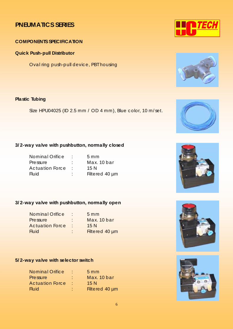
COMPONENTS SPECIFICATION Quick Push-pull Distributor Oval ring push-pull device, PBT housing Plastic Tubing Size HPU04025 (ID 2.5 mm / OD 4 mm), Blue color, 10 m/set.
3/2-way valve with pushbutton, normally closed
Nominal Orifice : 5 mm Pressure : Max. 10 bar Actuation Force : 15 N Fluid : Filtered 40 µm
3/2-way valve with pushbutton, normally open Nominal Orifice : 5 mm Pressure : Max. 10 bar Actuation Force : 15 N Fluid : Filtered 40 µm 5/2-way valve with selector switch Nominal Orifice : 5 mm Pressure : Max. 10 bar Actuation Force : 15 N Fluid : Filtered 40 µm

PNEUMATICS SERIES
7
Pressure gauge Operating pressure range 0 ~ 10 bar, ABS casing. 3/2-way roller lever valve, Normally closed
Nominal Orifice : 2.5 mm Nominal Flow : 100 Nl/min at 6 bar Pressure : 2 ~ 10 bar Actuation Force : 6 N Fluid : Filtered 40 µm
3/2-way roller lever valve, with idle return, Normally closed
Nominal Orifice : 2.5 mm Nominal Flow : 100 Nl/min at 6 bar Pressure : 2 ~ 10 bar Actuation Force : 6 N Fluid : Filtered 40 µm
5/2-way single pilot valve
Nominal Orifice : 5 mm Pressure : Max. 10 bar Actuation Pressure: Min. 2.5 bar Fluid : Filtered 40 µm
5/2-way double pilot valve, pneumatically operated, both sides
Nominal Orifice : 5 mm Pressure : Max. 10 bar Actuation Pressure: Min. 1.0 bar Fluid : Filtered 40 µm
Logic element, “OR” function
Nominal Orifice : 2.5 mm Nominal Flow : 100 Nl/min at 6 bar Pressure : 2 ~ 10 bar Fluid : Filtered 40 µm

PNEUMATICS SERIES
8
Logic element, “AND” function
Nominal Orifice : 2.5 mm Nominal Flow : 100 Nl/min at 6 bar Pressure : 2 ~ 10 bar Fluid : Filtered 40 µm
Time-delay valve, normally closed High-flow timer for automatic return
Pressure : 2 ~ 10 bar Actuation : Min. 3 bar Flow rate : 800 Nl/min at 6 bar Delay-time : 0.25 ~ 5 sec. Fluid : Filtered 40 µm
Quick exhaust valve
Design : Diaphragm Pressure : 1 ~ 10 bar Housing : OT58 brass Seal Material : Polyurethane Fluid : Filtered 40 µm
One-way flow control valve
Nominal Orifice : 3.2 mm Nominal Flow Nominal Flow : 210 Nl/min at 6 bar Pressure : 2 ~ 10 bar Fluid : Filtered 40 µm
Pressure sequence valve
Design : Poppet Nominal Flow : 100 Nl/min at 6 bar Pressure : 2 ~ 8 bar Fluid : Filtered 40 µm

PNEUMATICS SERIES
9
Single Acting Cylinder (ISO 6432 Standard)
Magnetic, Spring return type, bore size 25 mm, stroke 50 mm, stainless steel barrel, rubber cushioned, 10 mm diame-ter hard-chrome rod, anodized aluminum bearing and cover cap, complete with PVC cam, nickel-plated one touch fittings and fasembly device. Max. operating pres-sure 10 bar, theoretical output trust and retraction force at 7 bar was 302 N and 254 N respectively. Operation : Single Acting Bore Size : 25 mm Stroke : 50 mm Pressure : Max. 10 bar Housing : Stainless Steel Seal : NBR
Double Acting Cylinder (According to ISO 6432 Standard)
Magnetic, bore size 25 mm, stroke 100 mm, stainless steel barrel, Rubber cushioned, 10 mm diameter hard-chrome rod, anodized aluminum bearing and cover cap, com-plete with PVC cam, nickel-plated one touch fittings and fasembly device. Max. operating pressure 10 bar, theo-retical output trust and retraction force at 7 bar was 302 N and 254 N respectively. Operation : Double Acting Bore Size : 25 mm Stroke : 100 mm Pressure : Max. 10 bar Housing : Stainless Steel Seal : NBR
Pressure regulating with 3/2-way filter control valve, Adjustable pressure 0 ~ 12 bar
Complete with 3/2-way PBT housing shut-off valve, max. Oper-ating pressure 14 bar possible, with 5 µm filtration efficiency and metal bowl guard.
Inlet Pressure : Max. 14 bar at 20OC Outlet Pressure : 0.5 ~ 12 bar Gauge Range : 0 ~ 10 bar Nominal Flow : 1300 Nl/min Condensate Trap : 40 cm2

PNEUMATICS SERIES
10
Pressure regulator with pressure gauge
Max. operating pressure 14 bar, polyamide, fiberglass-reinforced housing. Inlet Pressure : Max. 14 bar at 20OC Outlet Pressure : 0.5 ~ 12 bar Gauge Range : 0 ~ 10 bar Nominal Flow : 1300 Nl/min
Distribution Manifold
Consist of 1 no. of inlet suitable for ∅6 mm tubing and 8 nos. of self-closing outlet suitable for ∅4 mm tubing. When the tubing remove from any of ∅4 mm outlet, the air will not release even though the ∅6 mm inlet is supply with pressurized air. ∅6 mm inlet shall be male elbow type with oval release ring.
Connection Components 1. Quick Push-pull Elbow Union Connectors Oval ring push-pull device, PBT housing 2. Quick Push-pull Straight Reducer Oval ring push-pull device, PBT housing 3. Quick Push-pull Union Straight Connectors Oval ring push-pull device, PBT housing 4. Tube End-plug Suitable for blocking the end of tubing size ∅2.5 mm inner di- ameter tubing. 5. Tube Cutter Stainless Steel knife, ABS housing, manually operated, suitable for cutting the polyurethane, nylon or teflon tubing size up to 15 mm outer diameter.
PNEUMATICS SERIES
11
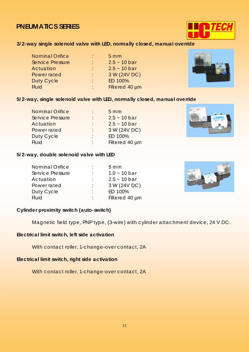
3/2-way single solenoid valve with LED, normally closed, manual override
Nominal Orifice : 5 mm Service Pressure : 2.5 ~ 10 bar Actuation : 2.5 ~ 10 bar Power rated : 3 W (24V DC) Duty Cycle : ED 100% Fluid : Filtered 40 µm
5/2-way, single solenoid valve with LED, normally closed, manual override
Nominal Orifice : 5 mm Service Pressure : 2.5 ~ 10 bar Actuation : 2.5 ~ 10 bar Power rated : 3 W (24V DC) Duty Cycle : ED 100% Fluid : Filtered 40 µm
5/2-way, double solenoid valve with LED
Nominal Orifice : 5 mm Service Pressure : 1.0 ~ 10 bar Actuation : 2.5 ~ 10 bar Power rated : 3 W (24V DC) Duty Cycle : ED 100% Fluid : Filtered 40 µm
Cylinder proximity switch (auto-switch) Magnetic field type, PNP type, (3-wire) with cylinder attachment device, 24 V DC. Electrical limit switch, left side activation With contact roller, 1-change-over contact, 2A Electrical limit switch, right side activation With contact roller, 1-change-over contact, 2A

PNEUMATICS SERIES
12
Relay Box, Two-fold
With terminal and power supply buses. Contact : 4 change-over switches Load : Max. 2A Pick-up time : 10 ms Drop-off time : 8 ms Mounting : Fasembly Click
Electrical signal button box Comprising one illuminated control switch and two illumi- nated. Momentary con tact switches; with terminal and power supply buses. Contact : 2-makes, 2-breaks
Load : Max. 2A Indicator : Illuminated type Mounting : Fasembly Click
Electrical Indicator and buzzer box Comprising six indicator lamp, with terminal and power sup -ply buses. Acoustic indicator : 1 Light indicator : 6 Mounting : Fasembly Click
Pneumatic-Electrical Converter (PE Converter)
Adjustable type, service pressure 0.5 ~ 8 bar.

PNEUMATICS SERIES
13
Power supply unit
Desktop type Input voltage 220 ~ 240 VAC/50 Hz Output voltage 24 V DC, 5A Short Circuit protection
Cable set for electro-pneumatics equipment set
Universal flexible leads with ∅ 4mm stackable safety plugs on both ends. Cables set includes : Qty. Length (mm) Color 10 50 Blue 11 300 Blue 12 500 Blue 3 1000 Blue 1 1500 Blue 10 50 Red 26 300 Red 21 500 Red 3 1000 Red 1 1500 Red
Portable Compressor Unit, UC-PNE-COMP (Optional) This is a oil-lubricated portable vertical stand air compressor suitable for classroom or lecture hall application. Following is a detail specification :-
Voltage : 230 V (50 Hz) Motor : 0.46 HP (0.34 kW) Displacement : 50 l/min (1.77 cfm) Max. Pressure : 8 bar (120 psi) Power Consumption : 2.9 Amp Tank Size : 25 litre Weight : 29 kg Dimensions : 380 (L) x 380 (W) x 550 (H) mm Noise Level : 45 dB(A)/1 m
It come with necessary accessories.

PNEUMATICS SERIES
14
COURSEWARE & TEACHING MATERIAL 1. Basic pneumatic training system
a) Textbook, English Version 1.0 Pneumatic Technology Fundamental Level b) Workbook, English Version 1.0 Pneumatic Technology Fundamental Level
c) OH Transparency Set “Pneumatic Technology” (Optional), UC-PNE-BS1-OT

PNEUMATICS SERIES
15
d) Magnetic Symbol Set, Pneumatics and Electro-Pneumatics (Optional), UC-PNE-BS1-MGS or UC-EPNE-BS1-MGS
Contains pneumatics, proximity switches, electro-pneumatics normally open and normally closed mechanical and relay contacts symbol. Suitable for sticking to magnetic white board.
e) Video Cassette (Optional), UC-PNE-BS1-VHS or UC-EPNE-BS1-VHS covered topics :
• “The Power of Pneumatics” • “The Pneumatic Circuit” • “Pneumatic Control Valves” • “Working Safely with Pneumatic System” • “Pneumatic System Maintenance” • “Troubleshooting Pneumatic Systems”
f) Cut-away Model Case (Optional), UC-PNE-BS1-SECT
Contains 24 models of pneumatics cut-away industrial standard compo- nents (Arrange in ABS Case)
1) Single-acting cylinder 2) Double-acting cylinder 3) One-way flow control valve
4) Logic “OR” element 5) Logic “AND” element 6) Logic “YES” element 7) Logic “NOT” element 8) Quick exhaust valve 9) 3/2-way single pilot valve 10) 3/2-way double pilot valve 11) 5/2-way single pilot valve 12) 5/2-way double pilot valve 13) Filter-regulator unit 14) Double-acting Rodless Cylinder 15) Magnetic Proximity Switch

PNEUMATICS SERIES
16
16) 3/2-way Single Solenoid Valve 17) Pneumatic-Electrical Converter 18) Optical Display 19) 5/2-way Single Solenoid Valve 20) 5/2-way Double Solenoid Valve 21) Solenoid Operator 22) Solenoid Coil 23) Pneumatic Pressure Switch 24) 5/3-way, Double solenoid valve, with manifold
g) Computer Aided Learning for Pneumatic Technology (Optional), UC-PNE-BS1-IV It is a software designed to teach the pneumatic circuits which covered the theory and practical exercises h) Automation Studio V5.0, Pneumatic Package (Optional) With Pneumatic and Electrical Control Libraries
This software tools enable the students to create their own designs by simply click of the mouse, instantly trigger the simulation mode and bring the circuit to life. It is an integrated software package that allows users to design, simu-late and animate circuits consisting of various automation technologies in-cluding pneumatics and electrical control. The software supports an I/O interface kit that can be connected to real ex-ternal devices via PC.
Specification:- a) The version contains basic module, pneumatic and electrical control li-brary. b) Import .SIM files
Some of the Example Cut-away Model

PNEUMATICS SERIES
17
c) Standalone editing and simulation. d) Prints to standard engineering sizes including ANSI A-E and ISC. e) Rubber banding keeps lines connected to components. f) Windows 2000 compatible. g) Check connection for easy troubleshooting. h) Includes basic graphical shapes and text func-tion to complement circuit documentation. i) Support ISO 1219-1/-2 as well as American and European graphical standard. j) Adjustable flow and pressure controls. k) Full-color simulation and component cross-section animation. l) Multiple document interface m) Export to DXF format n) Imports pneumatic manifold configuration from VSC configuration software o) All standard CAD features are available in a user-friendly fashion. p) Interface to external devices is possible. q) Provides animation of cross-section of pneumatic components.
2. Basic Electropneumatic Training System a) Textbook, English Version 1.0 Electropneumatic Technology Fundamental Level b) Workbook, English Version 1.0 Electropneumatic Technology Fundamental Level

PNEUMATICS SERIES
18
c) OH Transparency Set “Electropneumatic Technology” (Optional), UC-EPNE-BS1-OT
d) Magnetic Symbol Set, Pneumatics and Electro-Pneumatics (Optional), UC-PNE-BS1-MGS or UC-EPNE-BS1-MGS
Contains pneumatics, proximity switches, electro-pneumatics normally open and normally closed mechanical and relay contacts symbol. Suitable for sticking to magnetic white board.

PNEUMATICS SERIES
19
e) Video Cassette (Optional), UC-PNE-BS1-VHS or UC-EPNE-BS1-VHS covered topics :
• “The Power of Pneumatics” • “The Pneumatic Circuit” • “Pneumatic Control Valves” • “Working Safely with Pneumatic System” • “Pneumatic System Maintenance” • “Troubleshooting Pneumatic Systems”
f) Drawing Template (Optional), UC-EPNE-BS1-DTEMP
g) Computer Aided Learning for Pneumatic Technology (Optional), UC-EPNE-BS1-IV It is a software designed to teach the electropneumatic circuits which cov -ered the theory and practical exercises h) Automation Studio V5.0, Pneumatic Package (Optional) With Pneumatic and Electrical Control Libraries
This software tools enable the students to create their own designs by simply click of the mouse, instantly trigger the simulation mode and bring the circuit to life. It is an integrated software package that allows users to design, simu-late and animate circuits consisting of various automation technologies in-cluding pneumatics and electrical control. The software supports an I/O interface kit that can be connected to real ex-ternal devices via PC.
Specification:- a) The version contains basic module, pneumatic and electrical control li-brary. b) Import .SIM files c) Standalone editing and simulation. d) Prints to standard engineering sizes including ANSI A-E and ISC. e) Rubber banding keeps lines connected to components. f) Windows 2000 compatible. g) Check connection for easy troubleshooting. h) Includes basic graphical shapes and text function to complement circuit documentation. i) Support ISO 1219-1/-2 as well as American and European graphical stan-dard. j) Adjustable flow and pressure controls. k) Full-color simulation and component cross-section animation. l) Multiple document interface

PNEUMATICS SERIES
20
m) Export to DXF format n) Imports pneumatic manifold configuration from VSC configuration soft-ware o) All standard CAD features are available in a user-friendly fashion. p) Interface to external devices is possible. q) Provides animation of cross-section of pneumatic components.

PNEUMATICS SERIES
21
ORDERING INFORMATION
STANDARD PACKAGE
UC-PNE-BS1 BASIC PNEUMATIC TRAINING SYSTEM : 1 x Set of equipment for basic pneumatic 1 x Workbook 1 x Textbook
UC-EPNE-BS1 BASIC ELECTROPNEUMATIC TRAINING SYSTEM : 1 x Set of equipment for basic pneumatic 1 x Workbook 1 x Textbook 1 x Accessories Set
OPTIONAL ITEMS UC-CPM1A-20CDR-D OMRON 20 I/O CPM1A with Programming Console and
RS232 Converter UC-PNE-MW / UC-EPNE-MW
Mobile Workstation
UC-PNE-COMP Portable compressor unit UC-PNE-BS1-OT OH Transparency Set “Pneumatic Technology” UC-EPNE-BS1-OT OH Transparency Set “Electropneumatic Technology” UC-PNE-BS1-MGS / UC-EPNE-BS1-MGS
Magnetic symbols set, pneumatic & electropneumatic
UC-EPNE-BS1-DTEMP Drawing template. UC-PNE-BS1-VHS / UC-EPNE-BS1-VHS
Video cassettes.
UC-PNE-BS1-IV Computer aided learning for pneumatic technology.
UC-PNE-BS1-SECT Cut-away model case. AUTOMATION STUDIO V5.0, PNEUMATIC PACK-AGE
Automation Studio V5.0, Pneumatic Package
UC-EPNE-BS1-IV Computer aided learning for electropneumatic technology
Due to constant upgradation in products, specifications are subject to change without notice.