basic principles of gamma camera imaging and...
TRANSCRIPT
Basic Principles of Gamma Camera Imaging and Quality Control
Sharon L. White, PhD
University of Alabama at Birmingham
July 16, 2015

Page 2
Disclosures
No financial disclosures.
Gamma camera images and photographs of
equipment are for illustrating concepts and not
intended to advertise or endorse any particular
manufacturer or vendor.

Page 3
Learning Objectives
1. Understand basics of operation of conventional
gamma cameras.
2. List performance characteristics of gamma
cameras and features affecting performance.
3. List basic gamma camera calibrations and how
they affect performance.
4. List QC tests for gamma cameras required by
accrediting organizations.
5. Describe how to perform basic QC tests and
assess acceptable performance.

Gamma Cameras –Dual Head
4

Gamma Camera Operation
g
g
Array of Photomultiplier Tubes (PMTs):
Localizes the position where the gamma ray
interacts in the crystal
Sodium Iodide crystal:
A gamma ray from the patient interacts
and produces visible light photons
Collimator:
Forms a projection image by
allowing only gamma rays traveling
in certain directions to reach crystal (for
a parallel hole collimator, gamma rays
approximately perpendicular to crystal
pass through).
Gamma rays emitted from patient
g
5

Page 6
Conventional Gamma Cameras
Two detectors (heads) most common, although
single head and triple head cameras are used
Each head has single large NaI (sodium
iodide) crystal, up to 40 cm X 60 cm. Typical
crystal thickness: 3/8 or 5/8 inch
Array of photomultiplier tubes, typically ~ 50
per head

Page 7
Position Determination
The point where the gamma ray hits the crystal
is determined by a weighted average of the
signals from the group of PMTs receiving light
from that event.
The collimator localizes the origin of the
gamma ray as somewhere along a specific line
through the patient, since only gamma rays
traveling parallel to the holes will go through.
(Except for occasional septal penetration.)
Page 8
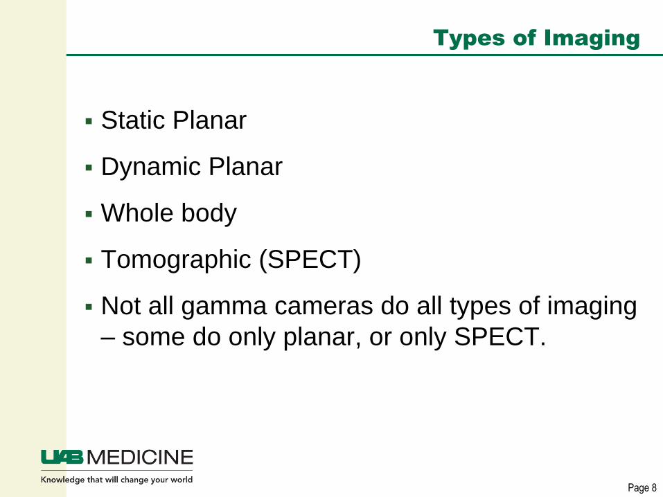
Types of Imaging
Static Planar
Dynamic Planar
Whole body
Tomographic (SPECT)
Not all gamma cameras do all types of imaging
– some do only planar, or only SPECT.

SPECT Operation
Camera heads rotate around patient, acquiring a set of
projection images that are reconstructed into slices 9
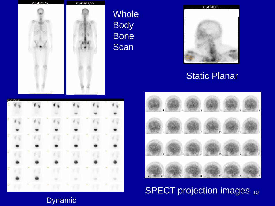
Whole
Body
Bone
Scan
Static Planar
SPECT projection images Dynamic
10

Page 11
Performance Characteristics
Spatial Resolution
Efficiency/Sensitivity
Energy resolution

Spatial Resolution • Intrinsic resolution (Rint) refers to how well the
crystal and PMT system localize an interaction
in the crystal. Affected by crystal thickness,
gamma ray energy, scatter in crystal.
• Collimator resolution (Rcoll) refers to how well
the collimator localizes the gamma ray source
in the patient, affected by hole diameter and
length, distance from collimator to patient.
• System resolution (Rsys) is a combination of
intrinsic and collimator resolution:
12

Page 13
Intrinsic Spatial Resolution
Affected by statistical fluctuations in number of
light photons produced by scintillator.
More light photons improves statistics, causing
less significant fluctuation in signal size and more
accurate positioning
Intrinsic spatial resolution improves with
increasing gamma ray energy, up to ~ 250 keV.
At higher energies scatter in the crystal becomes
more significant. Scatter can cause mispositioned
events, degrading resolution.

Page 14
Intrinsic Spatial Resolution
A thinner crystal has better intrinsic resolution
than a thicker one – less spreading of light
and multiple scatter events less likely to be
detected.
Typical intrinsic resolution is 3.5 to 4.5 mm,
depending on crystal thickness
Crystal thickness a tradeoff between spatial
resolution and efficiency – thinner crystals
have worse efficiency than thicker ones.

Bar pattern using Thallium, one
peak at a time
Lower energy peak only, 69 keV Upper energy peak only, 167 keV –
Better resolution at higher energy 15

Page 16
Collimators
Parallel hole collimators used most commonly
Different collimators available for different
energy radionuclides – medium energy for 111In and 67Ga, high energy for 131I
Different choices available for favoring high
resolution vs. high sensitivity
Parallel hole collimator produces image same
size as object – no magnification or
minification.

Page 17
Collimators and Scatter
Gamma rays undergoing Compton scatter in
the patient can pass through collimator holes
as well as unscattered ones.
A scattered photon has lower energy than the
initial photon. Scattered photons in the image
are reduced by energy discrimination, although
some scattered photons are still included when
their energy loss is small enough that they are
inside the allowed energy window.
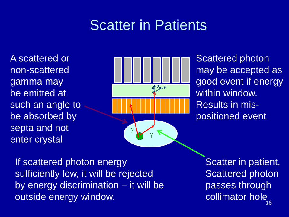
g
Scatter in patient.
Scattered photon
passes through
collimator hole
If scattered photon energy
sufficiently low, it will be rejected
by energy discrimination – it will be
outside energy window.
Scattered photon
may be accepted as
good event if energy
within window.
Results in mis-
positioned event
Scatter in Patients
g
A scattered or
non-scattered
gamma may
be emitted at
such an angle to
be absorbed by
septa and not
enter crystal
18
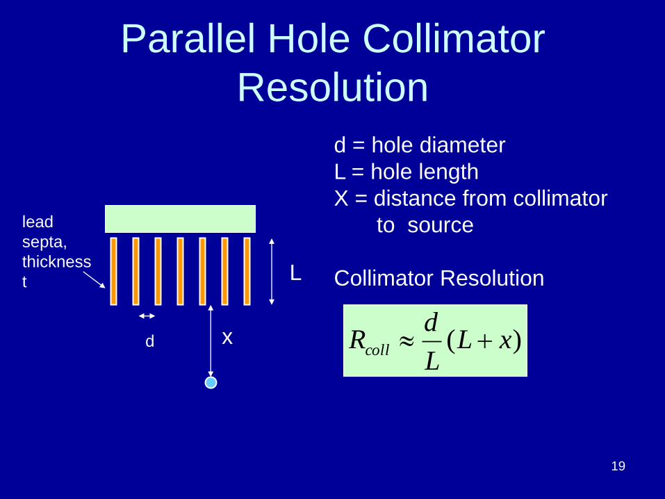
Parallel Hole Collimator
Resolution
lead
septa,
thickness
t
d
d = hole diameter
L = hole length
X = distance from collimator
to source
Collimator Resolution
x
L
)( xLL
dRcoll
19

At collimator surface 5 cm from surface
10 cm from surface
Collimator resolution gets
worse as source moves away
from collimator
surface. Important to position
patient as close as
possible to collimator
20

Collimator Specifications Type Hole
Diameter
(mm)
Septal
Thickness
(mm)
Hole
Length
(mm)
Coll.
Res. At
10 cm
(mm)
System
Res at 10
cm (mm)
9.5 mm
crystal
LEGP 1.40 0.180 24.7 8.0 8.8
LEHR 1.40 0.152 32.8 6.3 7.4
MEGP 2.95 1.143 48.0 10.7 11.3
HEGP 3.81 1.727 60.0 12.0 12.5
HEHR 3.06 1.95 60.0 9.6 10.4 21

Page 22
Other collimator types
Pinhole – forms magnified view of small
object, such as thyroid. Image is inverted.
Diverging – produces minified image, for
imaging large object (e.g. lungs) on smaller
detector area. No longer common.
Converging – produces non-inverted,
magnified view of small object. Not commonly
used.
Fanbeam – hybrid of parallel hole and
converging, sometimes used in brain SPECT

Page 23
Efficiency or Sensitivity
Refers to fraction of emitted gamma rays
detected and used to form image
Efficiency has intrinsic component based on
the thickness of the crystal and the attenuation
coefficient of the scintillation material (how
likely that a gamma ray is absorbed and
detected rather than just pass through)
Thicker crystal will have higher efficiency, at a
cost of decreased spatial resolution.

Page 24
Efficiency or Sensitivity
System efficiency is a combination of intrinsic
efficiency and collimator efficiency.
Collimator efficiency related to diameter and
length of holes, and thickness of septa.
Tradeoff between collimator spatial resolution
and efficiency.

Efficiency or Sensitivity
• Parallel hole collimator efficiency
proportional to:
d=hole diameter
L=hole length
t=septal thickness
d
L
æ
èç
ö
ø÷
2
´d 2
(d + t)2
25

Page 26
System Sensitivity
System sensitivity relatively low, <≈ .02 %,
due to necessity of absorptive collimation.
System sensitivity usually specified in
cpm/mCi at 10 cm for a specific radionuclide.
Typical values on the order of 150-170
cpm/mCi for Tc-99m for a low energy high
resolution collimator.
Page 27
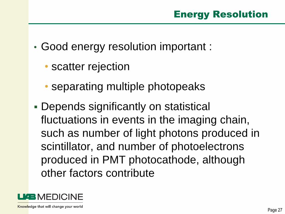
Energy Resolution
• Good energy resolution important :
• scatter rejection
• separating multiple photopeaks
Depends significantly on statistical
fluctuations in events in the imaging chain,
such as number of light photons produced in
scintillator, and number of photoelectrons
produced in PMT photocathode, although
other factors contribute

Page 28
Energy Resolution
Defined as FWHM of photopeak divided by
photopeak energy, expressed as percentage
Since it is energy dependent, for a gamma
camera usually specified for Tc-99m, typically
9-10% for conventional gamma cameras.

Page 29
Image Acquisition Options
Matrix size (examples are 64 X 64, 128 X 128,
256 X 256, 512 X 512)
Zoom factor (field of view)
Combination of matrix size and zoom factor
determines pixel size. Pixel size affects
resolution and noise in image, as well as slice
thickness in SPECT
Total counts and imaging time

Page 30
Image Acquisition Options
The following slides shows the effect of
different image acquisition options, such as
matrix size, zoom factor and total counts.
Planar images of four quadrant bar pattern and
SPECT phantom standing on end are used to
illustrate these options.

SPECT Phantom • Jaszczak Phantom
for SPECT quality
control.
• Approved by ACR
for SPECT ACR
accreditation images
• Standing on end,
used for evaluation
of planar spatial
resolution with
scatter – rod sizes:
12.7, 11.1, 9.5, 7.9,
6.4 and 4.8 mm
31

Page 32
Image Acquisition Options
The following slides shows the effect of matrix
size options ranging from 64 X 64 to 512 X
512
Total counts the same in each – 500K for
SPECT phantom and 5 M for bar pattern
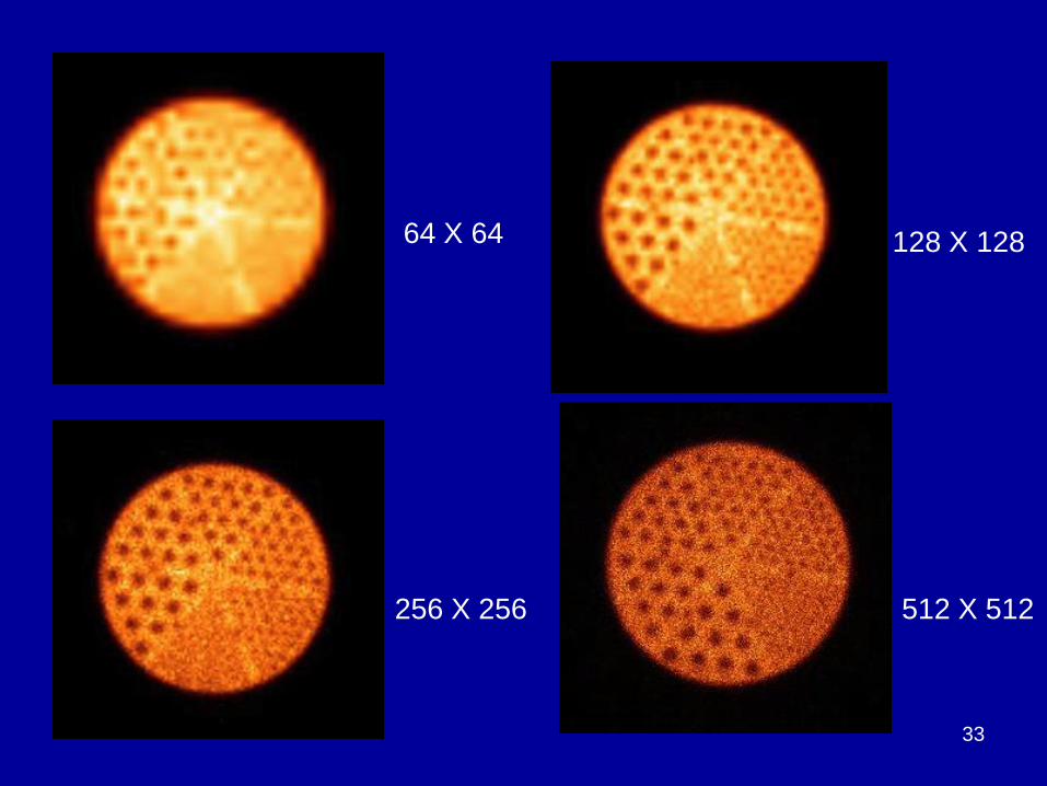
64 X 64 128 X 128
256 X 256 512 X 512
33

34
64X64
Pixel 8.8 mm 128 X 128
Pixel 4.4 mm
256 X 256
Pixel 2.2 mm
512 X 512
Pixel 1.1 mm
Bar spacings 2.0, 2.5, 3.0, 3.5 mm

Page 35
Image Acquisition Options
The following slide shows zoom options.
Matrix size 512 X 512 on each, but smaller
field of view used with Zoom 1.46 on second
one, resulting in smaller pixel size.

512 X 512 matrix,
1 M counts
512 X 512 matrix,
Zoom 1.46, 1 M counts
36

Page 37
Image Acquisition Options
The following slides show three images with
the same matrix size, 512 X 512
Total counts different in each
Counts per pixel higher with higher total
counts, causing images to be less noisy,
affecting visibility of rods or bars.

500K 1M
2M
All 512 X 512 Matrix
Total counts varies
38

39
1.25M 5M
20M 512 X 512 matrix
Total counts varies
From 1.25 M to 20 M

Page 40
Gamma Camera Calibrations
PMT gains must be balanced
Correction Tables:
Energy
Linearity
Uniformity (Flood)
Center of Rotation (COR) offset calibration for
SPECT-capable cameras.

Page 41
Correction Tables
Energy correction table corrects for variations
in measured energy across the detector
Linearity table corrects for non-uniform light
collection efficiency across face of
photomultiplier tubes, which causes straight
lines to appear wavy without correction
Flood table corrects for remaining non-
uniformities

Effects of Correction Tables
No
corrections
Energy
only
Energy
And
Linearity
Energy,
Linearity,
Uniformity
(all corrections)
99mTc Intrinsic Flood Images 42

Center of Rotation
Source
Pixel number
recording signal
128x128 matrix
63
65
Image acquisition
COR error
Backprojection
Offsets between physical center of
rotation and center of image matrix must
be corrected for.
Image
Matrix
1
1
43

What is the primary function of a
collimator in a gamma camera?
A. Protect the crystal
B. Define direction of incoming gamma rays entering crystal
C. Substantially eliminate scatter
D. Reduce count rate to prevent dead time
E. Shield the electronics 44
A. B. C. D. E.
0%
96%
0%0%4%

What is the primary function of a
collimator in a gamma camera A. Protect the crystal
B. Define direction of incoming gamma rays
entering crystal
C. Substantially eliminate scatter
D. Reduce count rate to prevent dead time
E. Shield the electronics
Reference: The Essential Physics of Medical
Imaging, JT Bushberg, JA Seibert, EM Leidholdt
Jr, JM Boone, 3rd edition, 2012, 680-681.
45

Which would improve spatial
resolution in gamma camera images?
A. Choose a camera with a
thicker crystal
B. Use a 64X64 matrix
rather than 256X256
C. Image with lowest energy
gamma rays available
D. Position patient as close
as possible to collimator
face 46
A. B. C. D.
0%
88%
8%4%

Which would improve spatial resolution in
gamma camera images?
A. Choose a camera with a thicker crystal
B. Use 64 X 64 matrix rather than 256 X 256
C. Image with lowest energy gamma ray available
D. Position patient as close to collimator face
as possible
Reference: The Essential Physics of Medical
Imaging, JT Bushberg, JA Seibert, EM Leidholdt
Jr, JM Boone, 3rd edition, 2012, 686-691.
Physics in Nuclear Medicine, SR Cherry, JA
Sorenson, ME Phelps, 4th edition, 2012,365-366.
47

Page 48
Quality Assurance
Routine QC tests are performed daily and
weekly, typically by technologists
Physicists should perform annual
assessments.
Accrediting bodies provide standards for
annual tests

Page 49
Joint Commission Requirements
Effective July 1, 2015, at least annually,
assess:
Image uniformity/system uniformity
High contrast resolution/system spatial
resolution
Sensitivity
Energy Resolution
Count Rate Performance
Artifact evaluation

Page 50
American College of Radiology Accreditation
At least annually:
Intrinsic uniformity
System uniformity
Intrinsic or System spatial resolution
Relative sensitivity
Energy Resolution
Count Rate Parameters
System performance for SPECT: tomographic
uniformity, contrast and spatial resolution

Page 51
Intersocietal Accreditation Commission
(IAC) Recommendations
Guidelines for annual tests include:
Overall system performance may be
evaluated with a fillable phantom with cold
inserts of different sizes and visually inspect
resulting images
Collimator integrity, comparing intrinsic and
extrinsic floods, should be performed as well
as visual inspection of collimators

Page 52
Routine QC - Uniformity
Uniformity must be checked every day that
gamma camera is used, before the first patient
Uniformity (flood) image may be acquired with
collimator on for system (extrinsic) uniformity or
collimator off for intrinsic uniformity
5 million counts adequate for daily QC for large
FOV camera, use 256 X 256 or 512 x 512 matrix
(manufacturer may have specific
recommendations)

System Uniformity
57Co sheet source
10-15 mCi when new
122 keV g
Half life 270 days
Water filled sheet source
Add 10-15 mCi 99mTc
140 keV g
Half life 6 hours
With collimator on, use planar sheet source:
53
Page 54
Intrinsic Uniformity
General method – use ~ 500 mCi 99mTc point
source, placed at a distance of five times the
length of the camera field of view
Some cameras have a special source holder
and vendor specific procedure which allows the
source to be closer

Page 55
Uniformity- Annual Testing
Acquire intrinsic uniformity images with Tc-
99m at low and high count rates – often the
daily QC is only done with Co-57.
Low count rate, typically 20-40 kcps, high
count rate, 65-80 kcps, but refer to
manufacturer’s recommendations.
The high count rate acquisition provides
assessment of camera’s function at higher
count rates – modern cameras should still
have good uniformity.

Good uniformity images
56

Poor uniformity
57

Uniformity - Quantification
Integral Uniformity should be < 5% for 5M count extrinsic flood
for camera following NEMA method for calculation. Refer to vendor
specifications. 58

59

60

Page 61
Spatial Resolution and Linearity
Routine QC - Image bar pattern at least weekly, extrinsically or intrinsically, to check spatial resolution and linearity
Confirm that smallest resolvable bar pattern remains the same with no abrupt changes
Ensure that bars do not appear significantly wavy, and no abrupt change in appearance
2.5 M counts adequate for weekly QC
Annual test do intrinsic bars. 5 M counts is required for ACR accreditation submission. Be very careful using bar pattern with collimator off.

Spatial Resolution – Four Quadrant
Bar Pattern
62
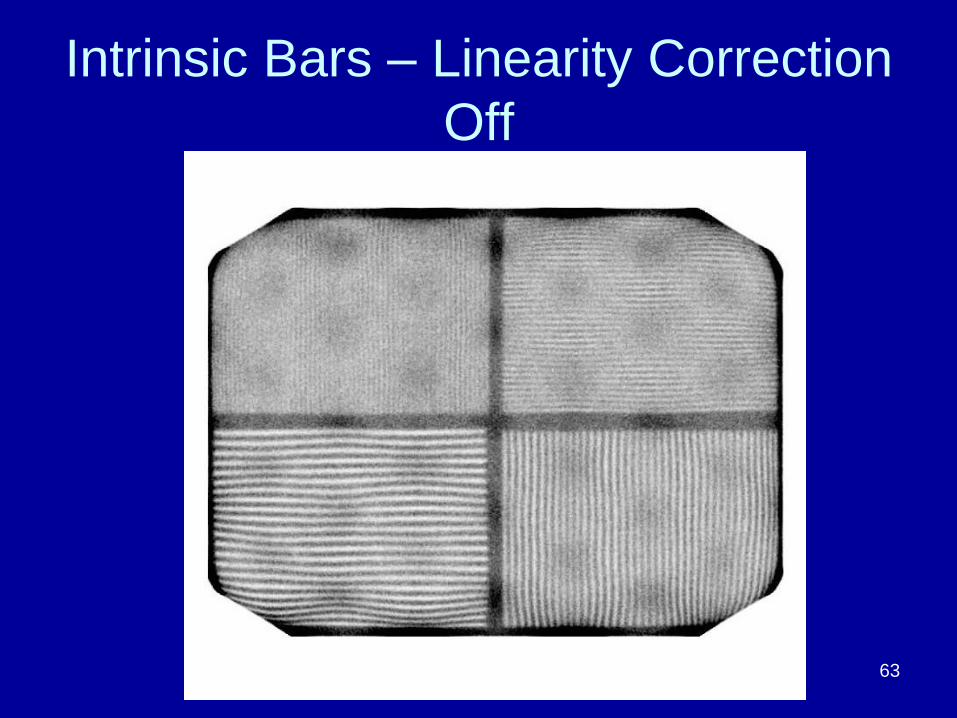
Intrinsic Bars – Linearity Correction
Off
63

Page 64
Extrinsic Resolution (FWHM) with Line
Source
Image a thin line source (plastic or glass tube)
filled with 99mTc, (at least ~ 1mCi/ml) 10 cm
from collimator
Use matrix size so that pixel size less than
about 1/5 expected FWHM
Draw profile across image to produce curve of
counts vs. pixel
Determine FWHM with available software, or
other means

Line source profile and curve
FWHM= 7 pixels =
7.7 mm
65

System Resolution with Scatter
Tc-99m Tl-201
Static images of SPECT phantom standing on end on top of
collimator. Provides a measure of planar system resolution with
scatter.
66

Measuring Sensitivity
– Place ~1-2 mCi 99mTc, and small volume of water in plastic flat-bottomed vial on top of Styrofoam cup 10 cm from collimator face.
– Record exact activity and time
– Count for 1 min, also count and subtract background
– Use total counts in image, not an ROI drawn around image 67

Page 68
Measuring Sensitivity
• Compute cpm/mCi and compare with vendor
specifications, also check that both heads
have comparable sensitivity (within about 5%)
• If camera is off peak it will affect results, also
ensure window width is same as
manufacturer’s specification
• A syringe will give comparable results, use a
small volume spread out through syringe
rather than a tiny point source
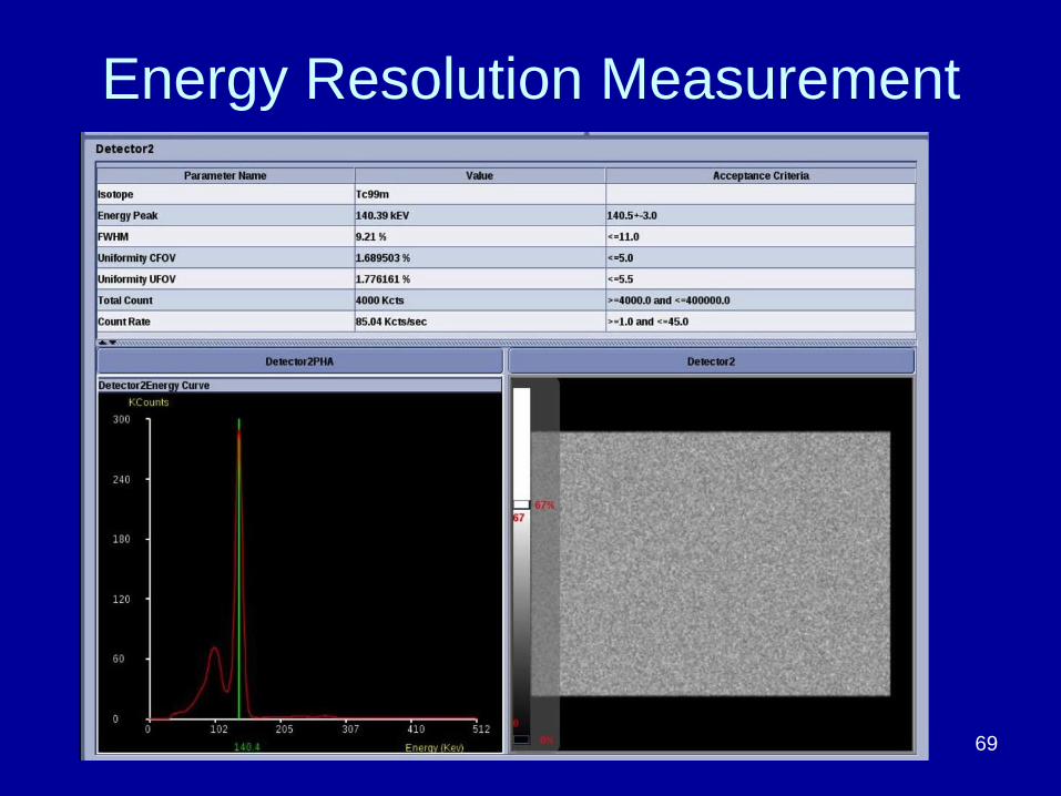
Energy Resolution Measurement
69

Estimating Energy Resolution
• Estimate ~ 9% energy resolution – photopeak width is approximate width of 9% window at half the peak height
70

Page 71
Count Rate Performance
Measure maximum count rate with point
source and collimator off. Approach camera
with point source and observe count rate go
up, until close enough that it decreases due to
dead time. Note maximum count rate (a good
estimate). Quickly move source away.
Acquire uniformity images at high count rate
and ensure uniformity is still reasonable (65-80
kcps for most newer cameras, older cameras
may have performance degradation at lower
count rates)

Low to High Count Rate Intrinsic
Floods
19 kcps 79 kcps
109 kcps
(too high
without high
count rate
mode
corrections)
72

Page 73
SPECT Image Quality
Acquire images with SPECT phantom to
evaluate contrast, resolution and uniformity,
including artifact evaluation

SPECT Phantom Imaging
• Deluxe version has spheres of diameters: 31.8, 25.4, 19.1, 15.9, 12.7, 9.5 mm
• Rods of diameters: 12.7, 11.1, 9.5, 7.9, 6.4 and 4.8 mm
74

Page 75
SPECT phantom imaging procedure
Make sure largest sphere lined up with largest rod section (rotate if needed)
Fill phantom with ~20-25 mCi 99mTc for high res collimator. Count rate should be < 30kcps
Use 99mTc sodium pertechnetate. Some radiopharmaceuticals may stick to the plastic or nylon screws and cause artifacts

Page 76
SPECT phantom imaging procedure
Center phantom in field of view
For cardiac cameras with 180 deg orbit, align largest sphere and rod section with center of leading detector for first frame.
ACR protocol is for 32 M total counts. Check count rate, adjust time per stop to achieve this.

Page 77
SPECT phantom imaging procedure
Use 128 X 128 matrix, 120 or 128 views over 360 degrees (180 degrees for a cardiac camera that cannot do 360 degree rotation) Adjust zoom factor as needed to achieve pixel size close to 3 mm. (ACR says 2.7 to 3.3 mm)1.33 to 1.46 are common zoom factors for large FOV camera
Use a radius of rotation as close to 20 cm as possible (an elliptical orbit is helpful)
Apply attenuation correction during image reconstruction.

SPECT phantom reconstructed
slices
78

SPECT phantom reconstructed slices –
no attenuation correction
79

Page 80
SPECT phantom image quality
Phantom images visually inspected for:
Resolution – smallest size of rods visible
Contrast – number of spheres visible
Uniformity – look for ring type artifacts or other
artifacts
For guidelines on acceptable image quality, refer
to ACR website for accreditation scoring criteria.
Criteria vary according to type of collimator and
radionuclide used (although currently it is only
required to submit SPECT images for Tc-99m)

Ring Artifacts
Ring artifacts
visible
81

Severe Ring Artifacts
82

Page 83
SPECT Ring Artifacts
Caused by non-uniformities such as:
Visible non-uniformities in flood image due to
camera being off peak, PMT gain imbalance, or
need for new correction tables
Shift in photopeak as camera head rotates
Collimator defect or damage (not visible in intrinsic
flood image)
Even small non-uniformities can cause ring
artifacts

Phantom filled with 99mTc Sestamibi
rather than Sodium Pertechnetate
Artifact
84

Which of these is not specifically listed as an
annual physics test required by TJC or
ACR?
85
13%
0%
74%
13% A. Sensitivity
B. Center of Rotation
C. Uniformity
D. Energy Resolution

Which of these is not specifically listed as an
annual physics test required by TJC or
ACR?
A. Sensitivity
B. Center of Rotation
C. Uniformity
D. Energy Resolution
References: The Joint Commission Revised Requirements
for Diagnostic Imaging Services,
http://www.jointcommission.org/assets/1/6/HAP-
CAH_DiagImag_Prepub_July2015release_20150105.pdf
ACR Nuclear Medicine Accreditation Program
Requirements, http://www.acr.org/Quality-
Safety/Accreditation/Nuclear-Med-PET
86

What is the primary cause of ring
artifacts in SPECT phantom images?
87
0%
0%
14%
86% A. Non-uniformities
B. Center of Rotation error
C. Phantom off center in field of view
D. Using the wrong matrix size

What is the primary cause of ring artifacts in
SPECT phantom images?
A. Non-uniformities
B. Center of Rotation error
C. Phantom off center in field of view
D. Using the wrong matrix size
Reference: The Essential Physics of Medical
Imaging, JT Bushberg, JA Seibert, EM Leidholdt
Jr, JM Boone, 3rd edition, 2012, 718-719.
88

Imaging and recording counts for a known
amount of activity in a small flask for 1 min is
a method of measuring _____?
89
4%
79%
4%
13% A. Uniformity
B. Spatial Resolution
C. Sensitivity
D. Energy Resolution

Imaging and recording counts for a known
amount of activity in a small flask for 1 min is
a method of measuring _____?
A. Uniformity
B. Spatial Resolution
C. Sensitivity
D. Energy Resolution
Reference: AAPM Virtual Library, 2012 Spring Clinical
Meeting, talk by James Halama: Nuclear Medicine-Testing
of Gamma Camera, SPECT and SPECT/CT Systems in a
Clinical Environment,
http://www.aapm.org/education/VL/vl.asp?id=125 90

Page 91
The End