basic research for improvement of road development...
TRANSCRIPT

Basic Research for Improvement of Road
Development Projects by Japan’s ODA
in African Countries
- Ethiopia, Ghana, Tanzania -
Site Survey Report
March 2013
JAPAN INTERNATIONAL COOPERATION AGENCY
Eight-Japan Engineering Consultants Inc.
Oriental Consultants Co., Ltd.
GL
JR
13-005

Site Photos in Ethiopia
E ‐ i
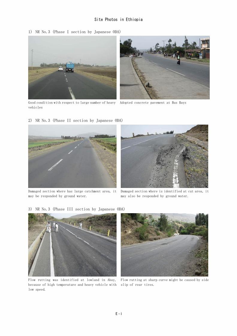
1) NR No.3 (Phase I section by Japanese ODA)
Good condition with respect to large number of heavy
vehicles
Adopted concrete pavement at Bus Bays
2) NR No.3 (Phase II section by Japanese ODA)
Damaged section where has large catchment area, it
may be responded by ground water.
Damaged section where is identified at cut area, it
may also be responded by ground water.
3) NR No.3 (Phase III section by Japanese ODA)
Flow rutting was identified at lowland in Abay,
because of high temperature and heavy vehicle with
low speed.
Flow rutting at sharp curve might be caused by side
slip of rear tires.

Site Photos in Ethiopia
E ‐ ii
In several portion, pavement was destroyed because
small and/or large scale land-slides have been
occurring in Abay
Heavy vehicles hauling lime-stone have been passing
in Abay. Travelling speed is lower than walking
speed.
4) NR No.1
Large number of flow rutting is identified on
climbing lane in lowland located around 1,000m in
height.
Bypass for NR No.1 is under construction by Chinese
contractor.
5) Weighbridge on NR No.1
Axle load check has been strictly doing in
cooperation with police.
Axle load is measured by each axle, regulated value
for front and rear axle is 8ton and 10ton a axle,
respectively.

Site Photos in Ghana
G ‐ i
1) NR No.1 (Accra – Tema Highway)
Four-lane concrete pavement which is improved under
leadership of the first president
Good condition after completion is kept by optimum
maintenance.
2) NR No.1 (George Bush Highway)
Six-lane road financed by Millennium Challenge
Corporation (MCC)
Adopted concrete pavement at Bus Bays
3) NR No.1 (Suburban Area)
Shoulder pavement destroyed by traffic for small
access road, because of thin layer (DBST)
Four-lane road with wide median strip which has
center drainage facilities
Site Photos in Ghana
G ‐ ii
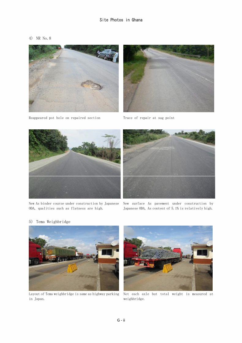
4) NR No.8
Reappeared pot hole on repaired section Trace of repair at sag point
New As binder course under construction by Japanese
ODA, qualities such as flatness are high.
New surface As pavement under construction by
Japanese ODA, As content of 5.1% is relatively high.
5) Tema Weighbridge
Layout of Tema weighbridge is same as highway parking
in Japan.
Not each axle but total weight is measured at
weighbridge.

Site Photos in Tanzania
T ‐ i
1) Kilwa Road in Dar es Salaam (Improved by Japanese ODA)
Flow rutting with large scale on outside lane of
carriage way
Bus Bay along Kawawa road, Semi-flexible pavement
was adopted for huge number of buses.
Center drainage on median strip, drainage system was
carefully designed.
Large pot hole and flow rutting on straight section
This phenomenon may be caused from thin layer with
flow rutting.
Side drainage was filled with water because of
breakage of crossing pipe.
Same as left photo. Downstream side of crossing pipe
was blocked with broken piece of pavement.

Site Photos in Tanzania
T ‐ ii
2) Challinze-Tanga Road (Rehabilitated by DANIDA)
Pavement slip was occurred at interlayer between new
surface and old surface. Thin new surface of 4cm may
be caused this slip.
Same as left picture
3) Kibaha-Challinze Section (Rehabilitated by TANROADS)
Long flow rutting on Kibaha-Challinze section. It
occurred after repair work by own budget.
A line of heavy vehicles on Kibaha-Challinze
section.(from Dar es Salaam to outside)
4) Kibaha Weighbridge
Weighbridge is located on both side of road. Under measuring, Axle load is measured by each axle.

Table of Contents
Page
1. Outline of the Basic Research
1.1 Background ················································································· 1- 1
1.2 Objectives ··················································································· 1- 2
1.3 Target Countries ············································································ 1- 3
1.4 Site Survey Schedule ······································································ 1- 4
2. Pavement Technology in Japan
2.1 Types and Applicable Conditions of Pavement ········································ 2- 1
2.2 Transitions in Pavement Design Methods in Japan ···································· 2- 6
2.3 Structural Design of Asphalt Pavement ················································· 2- 9
3. Applicable Standards in the Target Countries
3.1 Applicable Design Standards in the Target Countries ································· 3- 1
3.2 Related Survey Standards in the Target Countries ····································· 3- 2
3.3 Asphalt Blend Design ····································································· 3- 4
4. Conditions and Causes of Pavement Failure
4.1 Failure Conditions ········································································· 4- 1
4.2 Projected Causes of Failure ······························································· 4- 2
4.3 Implemented Pavement Failure Countermeasures ····································· 4- 14
Annex:Pavement Design Method in Japan (TA method)


図 表 一
【 Table 】
Table 2-1. The kind of pavement and a classification ·············································· 2- 2
Table 2-2 Summary and application of concrete pavement ········································ 2- 3
Table 2-3. Type of asphalt mixture ···································································· 2- 4
Table 2-4. The type of surface course mixture and characteristic and main use point ·········· 2- 5
Table 2-5. Concept of performance code ····························································· 2- 7
Table 2-6. Output of performance and the design of the pavement ······························· 2- 8
Table 2-7. Example of the elastic modulus and Poissons ratio ··································· 2- 10
Table 3-1. Geometric structural standard ····························································· 3- 1
Table 3-2. The pavement design method of survey target countries ······························ 3- 1
Table 3-3. Drainage method of survey target countries ············································ 3- 2
Table 3-4. Standard of the traffic volume survey in Ethiopia ······································ 3- 3
Table 3-5. Standard of the traffic volume survey in Ghana ········································ 3- 3
Table 3-6. Standard of the traffic volume survey in Tanzania ····································· 3- 3
Table 3-7. Subgrade surveyof target survey countries ·············································· 3- 3
Table 3-8. Mix design method for asphalt composite··············································· 3- 4
Table 3-9. Application condition of Refusal Density(Ethiopia) ······························· 3- 4
Table 4-1. Failure cause of the asphalt pavement (assumption) ································· 4- 2
Table 4-2. National highway traffic volume of Ethiopia ··········································· 4- 4
Table 4-3. Results of WT test ·········································································· 4- 4
Table 4-4. Measurement result of the surface of the pavement temperature ····················· 4- 5
Table 4-6. Possibility of a plasticity index (PI) and the expansion ································ 4- 11
Table 4-7. Plasticity index (PI) and shrinkage limit and expansion degree ······················ 4- 11
Table 4-8. The control situation of the overloading vehicle ······································· 4- 14
Table 4-9. Use example of such as the modified asphalt in survey target country ·············· 4- 15
Table 4-10. The dynamic stability that was used by an expressway project in Ethiopia ······· 4- 16
Table 4-11. Black cotton soil measures example in Ethiopia ······································ 4- 19
Table 4-12. Countermeasure standards for black cotton soil in different countries ············· 4- 20
【 Figure 】
Figure 2-1. Flow of the pavement design ···························································· 2- 8
Figure 2-2. Structure design of asphalt pavement ··················································· 2- 9
Figure 4-1. The overloaded actual situation in the TEMA observatory ·························· 4- 3
Figure 4-2. Relations of pavement temperature and the dynamic stability ······················ 4- 6
Figure 4-3. Tanzania:Trunk road test results(AC-20) ········································ 4- 7
Figure 4-4. Ethiopia:Trunk road testresults(AC-20) ·········································· 4- 7
Figure 4-5. Flow of water affecting the pavement ·················································· 4- 9
Figure 4-6. Flow of the water at Sag point(Mechanism of the pavement failure) ············· 4- 9
Figure 4-7. The pumping phenomenon ······························································· 4- 10
Figure 4-8 Condition of the soil and consistency limit ············································· 4- 13
Figure 4-9. Design example of the base course drainage in the United States ·················· 4- 18
Figure 4-10. Change standard typical cross section ················································· 4- 18
【 Photograph 】
Photograph 2-1 Asphalt pavement (left) and concrete pavement (right) ······················· 2- 1
Photograph 2-2.Dense graded mixture ······························································· 2- 5
Photograph 2-3.Porous asphalt mixture ······························································ 2- 5
Photograph 2-4.Construction example of the Semi-flexible pavement ··························· 2- 6
Photograph 4-1. Groundwater flowing down from the mountain side ·························· 4- 1
Photograph 4-2.Water in base course.Damage is seen in both sides across the bridge. ······ 4- 1
Photograph 4-3. For example rutting caused by fluidization of the surface course. ··········· 4- 1
Photograph 4-4. The truck which it is fully loaded with charcoal (Ghana) ···················· 4- 3
Photograph 4-5. Dump to be fully loaded with limestone, and to run (Ethiopia) ············· 4- 3
Photograph 4-6.Ssmall curve radius. ································································ 4- 5
Photograph 4-7. The speed is less than 5km/h. ···················································· 4- 5
Photograph 4-8. Etiopia: Rural trunk road ·························································· 4- 8
Photograph 4-9. Etiopia:Rural trunk road ·························································· 4- 8
Photograph 4-10. Ghana:Rural trunk road(2007) ··············································· 4- 8
Photograph 4-11. Ethiopia:Urban trunk road ······················································ 4- 8
Photograph 4-12. Ethiopia:Rural trunk road ······················································· 4- 8
Photograph 4-13. Tanzania:Rural trunk road ······················································ 4- 8
Photograph 4-14. The asphalt pavement that muddy water eructs by pumping ··············· 4- 10
Photograph 4-15. Black cotton soil in Ethiopia ····················································· 4- 11
Photograph 4-16. Black cotton soil(Dry) ························································· 4- 11
Photograph 4-17. Black cotton soil(Condition is before immersion in water) ·············· 4- 11
Photograph 4-18. Typical early case of the pavement failure by black cotton soil ············· 4- 12
Photograph 4-19. Highway section of the same area as photograph ······························ 4- 12
Photograph 4-20. Parking and stopping of the large car in the shoulder ························· 4- 12
Photograph 4-21. The passing vehicle which running a shoulder. ······························ 4- 12
Photograph 4-22. Mozyo axle load observation station ············································ 4- 14
Photograph 4-23. Tema axle load observation station(Ghana) ··································· 4- 14
Photograph 4-24. Trunk road (Reinforced concrete pavement)(Ghana) ·················· 4- 15
Photograph 4-25. Trunk road:Roller compacted concrete pavement(RCCP) ················· 4- 15

LIST OF ABBREVIATIONS
AASHTO :American Association of State Highway
and Transportation Officials
AC :Asphalt Concrete
AfDB :Africa Development Bank
As :Asphalt
BBR :Bending Beam. Rheometer
BS :British Standard
CBR :California Bearing Ratio
CIA :Central Intelligence Agency
CML :Central Material Laboratory
Co :Concrete
DANIDA :Danish International Development
Agency
DBM :Dense Bitumen Macadam
DBST :Double Bitumen Surface Treatment
DCP :Dynamic Corn Penetration
DD :Detail Design
DFR :Department of Feeder Roads
DMS :Detail Measurement Survey
DS :Design Standard
DS :Dynamic Stability
DSR :Dynamic Shear Rheometer
DT :Direct Tension
DUR :Department of Urban Roads
EN :Exchange of Note
ERA :Ethiopian Roads Authority
ERCC :Ethiopian Roads Construction
Corporation
ESAL :Equivalent Single Axle Load
EU :European Union
FAR :Federal Acquisition Regulation
FIDIC :Fédération Internationale Des
Ingénieurs-Conseils
FS :Feasibility Study
GA :Grant Agreement
GCW :Gross Combined Weight
GDP :Gross Domestic Product
GHA :Ghana Highway Authority
GNI :Gross National Income
GVW :Gross Vehicle Weight
HDM :Highway Development and
Management
HIPCs :Heavily Indebted Poor Countries
HWL :High Water Level
ITP :Inspection and Test Plan
IRF :International Road Federation
IRI :International Roughness Index
ISOHDM :International Study of Highway
Development and Management System
HGV :Heavy Goods Vehicle
JICA :Japan International Cooperation Agency
JIS :Japan Industrial Standard
JTF :Joint Task Force
JV :Joint Venture
LCC :Life Cycle Cost
MDL :Maximum density line
MGV :Medium Goods Vehicle
NEXCO :Nippon Expressway Company
NMT :Non-motorized Traffic
NTP :National Transport Policy
OD :Outline Design
ODA :Official Development Assistance
ORN :Overseas Road Note
PAV :Pressure Aging Vessel
PFI :Private Finance Initiative
PG :Performance Grade
PI :Plasticity Index

PI :Professional Indemnity
PIARC :Permanent International Association of
Road Congress
PMA :Polymer-modified Asphalt
PSI :Present Serviceability Index
PQ :Pre-qualification
QAM :Quality Assurance Manual
QAP :Quality Assurance Plan
QC :Quality Control
RCCP :Roller-compacted Concrete for
Pavement
RD :Rate of Deformation
RFI :Request for Inspection
RRL :Road Research Laboratory
RSDP :Road Sector Development Programme
SA :South Africa
SATCC :Southern Africa Transport and
Communications Commission
SBS :Styrene-butadiene-styrene
SCS :Soil Conservation Service
SGC :Superpave Gyratory Compactor
SHRP :Strategic Higway Research Program
SN :Structure Number
TANROADS:Tanzania Road Authority
TICAD :Tokyo International Conference on
African Development
TOR :Term of Reference
TPB :Treated Permeable Base
TRH :Technical Recommendations for
Highways
TRL :Transport Research Laboratory
TRRL :Transport and Road Research
Laboratory
TSDP :Transport Sector Development
Programme
TSIP :Transport Sector Investment Programme
UEMOA :Union Economique et Monetaire Ouest
Africaine
UN :United Nation
VEF :Vehicle Equivalent Factor
VHGV :Very Heavy Goods Vehicle
VMA :Voids in Mineral Aggregate
WB :World Bank
WC :Wearing Course
WT :Wheel Trucking

Basic Research for Improvement of Road Development Projects by Japan’s ODA in African Countries
- Ethiopia, Ghana, Tanzania -
1-1
1. Outline of the Basic Research
1.1 Background
It is commonly recognized in African countries that the transport sector is still underdeveloped.
Delays of development in this sector are one of the major barriers to economic growth and one
of the reasons for poverty. For this reason, development of the transport sector for transfer of
people and goods is an absolutely necessary condition for sustainable development and growth.
In particular, there is a high demand (need) for road improvement regardless of economic level.
Given this background, improvement of international roads, major urban roads and regional
roads has been promoted by continuous efforts of respective countries, and with cooperation of
development partners.
The Japan (JAPAN) is one of the major donors that have contributed to road development in
African countries. The road projects under Japan’s grant aid scheme are highly valued from the
aspects of quality control, schedule control and safety control due to the use of Japanese
standards in general.
In addition, JAPAN has continuously convened the Tokyo International Conference on African
Development (TICAD). Notably at TICAD IV in 2008, JAPAN committed to double the rate of
Official Development Assistance (ODA) for African countries until 2012. Under this
momentum, Japan International Cooperation Agency (JICA), the implementing arm of Japan’s
ODA, has been actively extending assistance for African countries, and road development /
improvement projects are given high priority.
In the operation of Japan’s ODA, it is important to assure a suitable level of product quality. In
this regard, any project should start with proper understanding of local conditions. Weather
conditions (temperature, rainfall, etc) and road management conditions (safety rules, over
loading, etc) in African countries are sometimes more severe than those observed in Japan.
Level and frequency of road maintenance are typically not the same as in Japan.
Under these conditions and in this construction environment:
A) Technical know-how and/or standards for design and construction based on experience in
Japan may not be applicable as defined, due to significant deviation of surrounding
environment such as weather conditions, soil conditions, axle load (control), traffic manner,
maintenance. Thus, standards for design, construction and quality control should be
carefully chosen to suite major local conditions, and various local expertise accumulated
based on past experiences and experiments must be sufficiently utilized.
B) Implementation system for construction works should be adequately organized by the
contractor/consultant with proper understanding of local resources such as sub-contractors.
Basic Research for Improvement of Road Development Projects by Japan’s ODA in African Countries
- Ethiopia, Ghana, Tanzania -
1-2
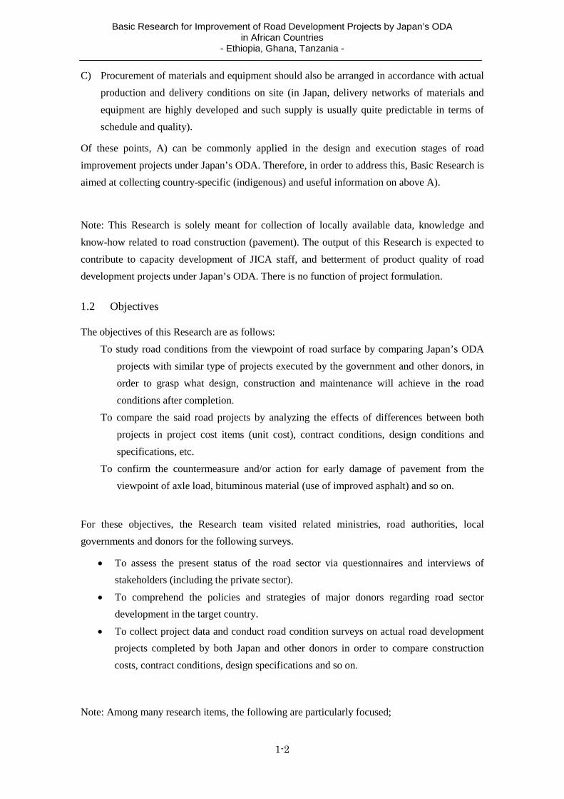
C) Procurement of materials and equipment should also be arranged in accordance with actual
production and delivery conditions on site (in Japan, delivery networks of materials and
equipment are highly developed and such supply is usually quite predictable in terms of
schedule and quality).
Of these points, A) can be commonly applied in the design and execution stages of road
improvement projects under Japan’s ODA. Therefore, in order to address this, Basic Research is
aimed at collecting country-specific (indigenous) and useful information on above A).
Note: This Research is solely meant for collection of locally available data, knowledge and
know-how related to road construction (pavement). The output of this Research is expected to
contribute to capacity development of JICA staff, and betterment of product quality of road
development projects under Japan’s ODA. There is no function of project formulation.
1.2 Objectives
The objectives of this Research are as follows:
To study road conditions from the viewpoint of road surface by comparing Japan’s ODA
projects with similar type of projects executed by the government and other donors, in
order to grasp what design, construction and maintenance will achieve in the road
conditions after completion.
To compare the said road projects by analyzing the effects of differences between both
projects in project cost items (unit cost), contract conditions, design conditions and
specifications, etc.
To confirm the countermeasure and/or action for early damage of pavement from the
viewpoint of axle load, bituminous material (use of improved asphalt) and so on.
For these objectives, the Research team visited related ministries, road authorities, local
governments and donors for the following surveys.
To assess the present status of the road sector via questionnaires and interviews of
stakeholders (including the private sector).
To comprehend the policies and strategies of major donors regarding road sector
development in the target country.
To collect project data and conduct road condition surveys on actual road development
projects completed by both Japan and other donors in order to compare construction
costs, contract conditions, design specifications and so on.
Note: Among many research items, the following are particularly focused;

Basic Research for Improvement of Road Development Projects by Japan’s ODA in African Countries
- Ethiopia, Ghana, Tanzania -
1-3
- Standard applicable to pavement structure design and design parameters such as reliability,
- Countermeasures for flow rutting of asphalt pavement from following viewpoints of:
over loading prevention (specific actions) ,
asphalt mix design with use of refusal density and Superpave (use of Gyratory
compactor) , etc,
combination use of mechanical test such as creep test, wheel trucking test and
LCPC test etc
change of pavement materials such as modified asphalt binder, cement concrete,
and semi-flexible pavement, etc
revision of pavement design standard or specification
- Standards applicable to drainage design and countermeasure for climate change (torrential
rain)
- Countermeasures applicable to problem soil such as expansive soils and dispersive soils, etc.
- Determination method of defect after completion (such as flow Rutting).
1.3 Target Countries
The following three countries have been selected as the focus of the Research, as these countries
are major recipient countries in the road sector from Japan and other donors:
Federal Democratic Republic of Ethiopia
Republic of Ghana
United Republic of Tanzania
Towards the above goal, the Research team will visit various organizations in both public and
private sector in target countries.

Basic Research for Improvement of Road Development Projects by Japan’s ODA in African Countries
- Ethiopia, Ghana, Tanzania -
1-4
1.4 Site Survey Schedule
1) 1st Site Survey Schedule
TANZANIA
No. of Day Date Research Items
1 5/10 (Thu) Leave for Tanzania
2 5/11 (Fri) Arrival at Tanzania
3 5/12 (Sat) Survey for city roads (urban rods)
4 5/13 (Sun) Survey for city roads (urban rods)
5 5/14 (Mon) AM: Meeting with JICA Office PM: Hearing to TANROADS
6 5/15(Tue) Hearing to EU, DANIDA, WB
7 5/16(Wed) Hearing to local consultant and contractor
8 5/17(Thu) Hearing to Dar es Salaam University Hearing to Central Laboratory
9 5/18(Fri) Hearing to Japan’s ODA Project
10 5/19(Sat) Hearing to Asphalt Plant
11 5/20(Sun) Data Collection
12 5/21(Mon) Reporting
13 5/22(Tue) Report to JICA Office and TANROADS
GHANA
No. of Day Date Research Items
14 5/23(Wed) Arrival at Ghana
15 5/24(Thu) AM: Meeting with JICA Office PM: Hearing to GHA
16 5/25(Fri) Survey for Japan’s ODA Project (R1)
17 5/26(Sat) Hearing to Japan’s ODA Project (R8)
18 5/27(Sun) Survey for regional roads
19 5/28(Mon) Survey for city roads (urban rods)
20 5/29(Tue) Hearing to EU, WB, ADB
21 5/30(Wed) Hearing to local consultant and contractor Hearing to Asphalt Plant
22 5/31(Thu) Data Collection and Reporting
23 6/1(Fri) Report to JICA Office and GHA
24 6/2(Sat) Reporting
ETHIOPIA
No. of Day Date Research Items
25 6/3(Sun) Arrival at Ethiopia
26 6/4(Mon) AM: Meeting with JICA Office, EOJ, JICA Expert PM:ERA HQ, ERA Central Region Office
27 6/5(Tue) Survey for Japan’s ODA Project (Phase 1,2,3,4)
28 6/6(Wed) Survey for Trunk Road (after Phase 4 by WB, Chinese Contractor) Hearing to Japan’s ODA Project (Kajima)
29 6/7(Thu) AM: Hearing to EU Hearing to local consultant and contractor PM: Survey for Trunk Road (Mojo-Awash by EU)
30 6/8(Fri) AM: Hearing to AACRA (Addis Ababa City Road Authority) Hearing to ERA (Axle Load Department) PM: Survey for Trunk Road (Addiss – Tamabel by GOE)

Basic Research for Improvement of Road Development Projects by Japan’s ODA in African Countries
- Ethiopia, Ghana, Tanzania -
1-5
*As pavement and countermeasure for BCS)
31 6/9(Sat) Survey for city roads (urban rods)
32 6/10(Sun) Reporting
33 6/11(Mon) AM: Hearing to WB, ADB PM: Hearing to Asphalt Plant
34 6/12(Tue) Hearing to Japan’s ODA Project (Awash Bridge)
35 6/13(Wed) Data Collection
36 6/14(Thu) Data Collection & Reporting
37 6/15(Fri) Report to JICA Office and ERA
38 6/16(Sat) Leave for Japan
39 6/17(Sun) Arrival at Japan
2) 2nd Site Survey Schedule
TANZANIA
No. of Day Date Research Items
1 8/19(Sun) Leave for Tanzania
2 8/20(Mon) Arrive at Tanzania
3 8/21(Tue) AM: Hearing to TANROADS PM: Hearing and discussion with Local Consultant
4 8/22(Wed) AM: Data collection from TANROADS PM: Hearing to the contractor for New Bagamoyo Road
5 8/23(Thu) AM: Survey for Kilwa Road PM: Survey for New Bagamoyo Road PM: Discussion with JICA
6 8/24(Fri) Survey for Chalinze-Tanga Road (DANIDA Project)
7 8/2(Sat) AM: Hearing and discussion with project manager for Chalinze-TangaProject
ETHIOPIA
No. of Day Date Research Items
8 8/26(Sun) Arrive at Ethiopia
9 8/27(Mon) AM: Discussion with JICA PM: Hearing and discussion with Local Consultant
10 8/28(Tue) Survey for NR No.3 (Phase I, II, III by Japan’s ODA)
11 8/29(Wed) Survey for NR No.3 (Phase I, II, III, IV by Japan’s ODA)
12 8/30(Thu) AM: Hearing to AACRA PM: Hearing and discussion with ERA PM: Reporting to EOJ
13 8/31(Fri) AM: Survey for Addis-Adama Highway PM: Data collection from ERA
14 9/1(Sat) Reporting
GHANA
No. of Day Date Research Items
15 9/2(Sun) Arrive at Ghana
16 9/3(Mon) AM: Discussion with JICA PM: Data collection and hearing to Local Consultant
17 9/4(Tue) AM: Data collection and hearing to GHA PM: Data collection and hearing to Local Consultant
18 9/5(Wed) Survey for city roads (e.g. George Bush HW)
19 9/6(Thu) AM: Reporting PM: Leave for Japan
20 9/7(Fri) Transit
21 9/8(Sat) Arrive at Japan

Basic Research for Improvement of Road Development Projects by Japan’s ODA in African Countries
- Ethiopia, Ghana, Tanzania -
1-6

Basic Research for Improvement of Road Development Projects by Japan’s ODA in African Countries
- Ethiopia, Ghana, Tanzania -
2-1
2. Pavement Technology in Japan
2.1 Types and Applicable Conditions of Pavement
(1) Types of Pavement
It is difficult to uniformly categorize types of pavement because descriptions and terms differ
according to the surface course materials, construction methods, functions and locations. In
practical terms, pavement can be broadly divided into asphalt pavement and concrete pavement.
Asphalt pavement refers to cases where the surface course is composed of asphalt mixture,
while concrete pavement refers to cases where the surface course is composed of cement
concrete.
These two types differ in terms of not only the surface course but also thinking on load
propagation. In the case of asphalt pavement, each course bears the stress and successively
dissipates the load, whereas in the case of cement concrete pavement, concrete plates on the
surface course bear the load, while the ground underneath the plates mainly serves to uniformly
support the surface course and secure easier execution. Due to these features, cement concrete
pavement is described as rigid pavement, while asphalt pavement is called flexible pavement.
Photograph2-1 Asphalt pavement (left) and concrete pavement (right)
Pavement is also divided into various types according to the blend, construction method and
anticipated functions. Table 2-1 shows types of pavement classified according to the surface
course materials, blend and construction method and function.
In terms of surface course materials, pavement is divided into the above-mentioned asphalt
pavement and cement concrete pavement as well other types. These can be classified according
to the type of binder used to bind the aggregate, and they are the most recognizable and
common category judging from surface observation too.

Basic Research for Improvement of Road Development Projects by Japan’s ODA in African Countries
- Ethiopia, Ghana, Tanzania -
2-2
Classifications based on blend and construction method are also deeply related to pavement
categories that have special functions and structures, and classifications are made according to
the type of asphalt, method of blending, method of load dissipation and existence or not of
reinforcing bars in concrete and so on.
Categories of asphalt pavement are as follows. Recycled asphalt pavement, which is made
from modified straight asphalt, and modified asphalt pavement, etc. differ according to the type
of asphalt. Rolled asphalt pavement and porous asphalt pavement are classified according to the
blend. Meanwhile, full-depth asphalt pavement and composite pavement are classified
according to structure. Semi-flexible pavement is an intermediate type of pavement that utilizes
the flexibility of asphalt mixture and the rigidity of cement concrete, however, because the base
material is asphalt mixture, it is classed as asphalt pavement.
Turning to cement concrete pavement, this is classified according to whether or not the
concrete plates contain iron or reinforcing bars, etc. Compacted concrete pavement is a category
based on the construction method, while composite pavement is a category of cement concrete
pavement based on structural characteristics, although the differences are not always clear.
In terms of functional classification, pavement is classified mainly according to the functions
that are required but categories do not indicate specific pavement types. Examples of functional
categories include pavement that is resistant to flow rutting, which is the biggest problem on
trunk roads, pavement that resists the abrasion that accompanies use of slip prevention measures
such as spiked tires and chains, etc. during the winter, drainage pavement that is designed to
quickly remove rain water and also reduce noise (as a secondary function), and light-colored
pavement, which is intended to improve visibility in driving.
Table2-1. The kind of pavement and a classification
Classification of surface course Work of pavement Classification of function Asphalt pavement Recycle asphalt pavement
Modified asphalt pavement Porous asphalt pavement Rolled asphalt pavement Full depth asphalt pavement
Plastic flow resistant pavement Wear resistance pavement Low noise pavement Drainage asphalt pavement Permeable pavement Bright color pavement Semi‐flexible pavement Colored pavement Safeguard pavement
Composite pavement Cement concrete pavement
Unreinforced concrete pavement Reinforced concrete pavement Continuously reinforced concrete pavement(CRCP) Roller compacted concrete pavement(RCCP) Precast concrete pavement
Others Neat pavement Plastic wastes pavement Blocks pavement
Source: Based on Journal of Pavement Engineering (Japan Society of Civil Engineering, 1995)

Basic Research for Improvement of Road Development Projects by Japan’s ODA in African Countries
- Ethiopia, Ghana, Tanzania -
2-3
(2) Main Functions and Applications of Concrete Pavement
Concrete pavement has cement concrete pavement plates for the surface course and is more
rigid than asphalt mixture course. Accordingly, it is referred to as rigid pavement as opposed to
asphalt pavement, which is called flexible pavement. The features of concrete pavement are as
follows: Initial construction cost is expensive because large machinery and curing are required;
however, because the pavement lasts a long time and entails low maintenance costs, its total cost over the long term is low.
Noise and vibration are more likely to occur due to the rough face finishing and joints for preventing slips.
Since there is no permanent deformation of the road surface or degradation of materials, the road life is long.
Repairs are relatively complicated and take a long time (days).
Source: Fundamentals of Pavement Engineering (Japan Society of Civil Engineers)
In Japan, car ownership mushroomed and road construction was rapidly promoted from the
1960s. As a result, asphalt pavement (including basic pavement), which incurs low construction
costs and allows roads to be quickly opened to traffic, was increasingly adopted, while the share
of concrete pavement decreased. Moreover, use of concrete pavement was increasingly avoided
due to the issues mentioned above.
Table 2-2 indicates the outline contents and applications of the main types of concrete
pavement.
Table 2-2 Summary and application of concrete pavement Type of concrete pavement Summary of Structure Applocation for japan
Reinforced concrete pavement Put a joint appropriate distance.And put a dowel bar and thai bar in the joint and connect each concrete slub. The most common concrete pavement
It is generally applied at a general road, the pavement in the tunnel, yard pavement.
Continuously reinforced pavement
Instead of putting a transverse joint, It scattered cracking by the rebar that setted a vertical direction, and keep continuity as the pavement. Characteristic. Run characteristics
Abbreviation of the maintenance work of the joint
There are the application results in some sections of the Japanese Expressway .
Roller compacted concrete pavement(RCCP)
Constructs a concrete of dry consistency with a littleunit weight of water by the same machine of normal asphalt pavement. Characteristic Construction speed is fast Curing time is short. Early traffic opening and Term of works
shortening.
It is applied partly on a local container yard, a tank way. There are extremely few applications on the general road.
Precast concrete pavement Produces a concrete slab by factory beforehand andthe joining, unification at site.
There are the results in some sections of MLIT, but there is extremely few it
Composite pavement Surface course or base course is an asphalt mixture.It puts a cement slab under the asphalt mixture. Life period is longer than normal asphalt pavement
There are the application results in some sections of Second Tomei Expressway, Chugoku Expressway.
Sorce:Creat by study team
Basic Research for Improvement of Road Development Projects by Japan’s ODA in African Countries
- Ethiopia, Ghana, Tanzania -
2-4
(3) Main Functions and Applications of Asphalt Pavement
Asphalt pavement is generally constructed by carrying heated asphalt mixture manufactured
in an asphalt mixture plant to the work site by dump truck, and leveling and compacting it by
using machinery. The features of asphalt pavement are as follows: Because the construction machinery is compact and conducts rapid work with no need for
curing, road can be opened to traffic at an early point. Accordingly, the construction cost is relatively cheap.
Because forming is simple, good road flatness can be achieved and noise is also relatively small.
Because the asphalt mixture tends to deform in high temperatures, it soon becomes rutted and loses its flatness, so its service life is short. It is not suited to airport aprons or freight yards and so on where heavy loads are left static for extended periods.
Because the pavement can be repaired using simple methods, it is suited to places that have underground structures.
Source: Fundamentals of Pavement Engineering (Japan Society of Civil Engineers)
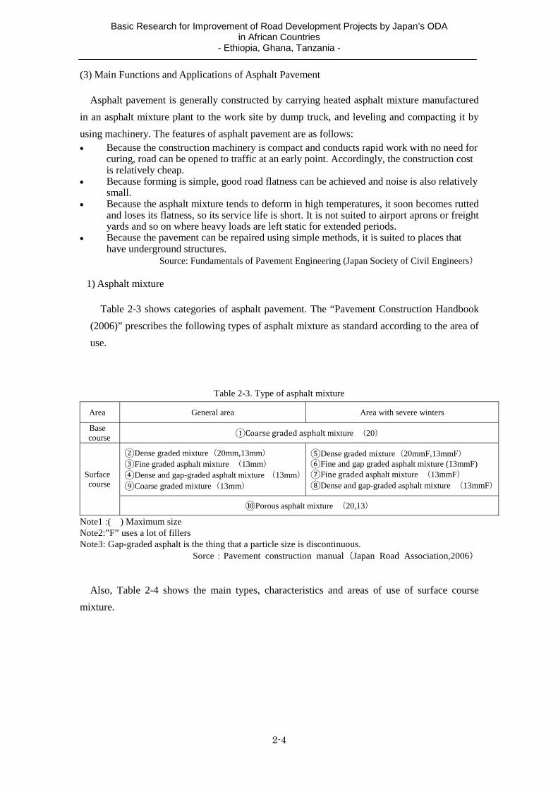
1) Asphalt mixture
Table 2-3 shows categories of asphalt pavement. The “Pavement Construction Handbook
(2006)” prescribes the following types of asphalt mixture as standard according to the area of
use.
Table 2-3. Type of asphalt mixture
Area General area Area with severe winters
Base course Coarsegraded asphaltmixture (20)
Surface course
Dense graded mixture(20mm,13mm) Fine graded asphalt mixture (13mm) Dense and gap-graded asphalt mixture (13mm) Coarse graded mixture(13mm)
Dense graded mixture(20mmF,13mmF) Fine and gap graded asphalt mixture (13mmF) Finegradedasphalt mixture (13mmF) Dense and gap-graded asphalt mixture (13mmF)
Porous asphalt mixture (20,13)
Note1 :( ) Maximum size Note2:”F” uses a lot of fillers Note3: Gap-graded asphalt is the thing that a particle size is discontinuous.
Sorce:Pavement construction manual(Japan Road Association,2006)
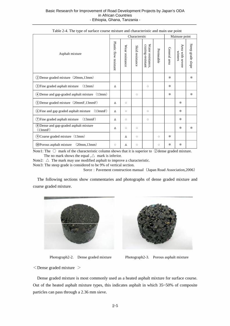
Also, Table 2-4 shows the main types, characteristics and areas of use of surface course
mixture.
Basic Research for Improvement of Road Development Projects by Japan’s ODA in African Countries
- Ethiopia, Ghana, Tanzania -
2-5
Table 2-4. The type of surface course mixture and characteristic and main use point
Asphalt mixture
Characterstic Mainuse point
Plastic flow
resistant
Wear resistance
Skid resistance
Water resistance,
crazing-resistant
Perm
eable
General area
Area w
ith severe w
inters
Steep grade slope
Dense graded mixture(20mm,13mm) * *
Fine graded asphalt mixture (13mm) *
Dense and gap-graded asphalt mixture (13mm) * *
Dense graded mixture(20mmF,13mmF) *
Fine and gap graded asphalt mixture (13mmF) *
Fine graded asphalt mixture (13mmF) *
Dense and gap-graded asphalt mixture (13mmF)
* *
Coarse graded mixture(13mm) *
Porous asphalt mixture (20mm,13mm) * *
Note1: The ○ mark of the characteristic column shows that it is superior to ②dense graded mixture. The no mark shows the equal ,△ mark is inferior.
Note2: △ The mark may use modified asphalt to improve a characteristic.Note3: The steep grade is considered to be 9% of vertical section.
Sorce:Pavement construction manual(Japan Road Association,2006)
The following sections show commentaries and photographs of dense graded mixture and
coarse graded mixture.
Photograph2-2. Dense graded mixture Photograph2-3. Porous asphalt mixture
<Dense graded mixture >
Dense graded mixture is most commonly used as a heated asphalt mixture for surface course.
Out of the heated asphalt mixture types, this indicates asphalt in which 35~50% of composite
particles can pass through a 2.36 mm sieve.

Basic Research for Improvement of Road Development Projects by Japan’s ODA in African Countries
- Ethiopia, Ghana, Tanzania -
2-6
<Coarse graded mixture >
In heated asphalt mixture, which is composed of coarse aggregate, fine aggregate, filler and
asphalt, mixture that contains large porosity is generically referred to as coarse graded mixture.
In a narrow sense, coarse graded mixture refers to asphalt in which 15~30% of composite
particles can pass through a 2.36 mm sieve and the mix design has been set based on the
Marshall stability test.
<Porous asphalt mixture >
Porous asphalt mixture is a type of the aforementioned coarse graded mixture. This is used as
the surface and binder course of drainage pavement and roadway permeable pavement.
(4) Functions and Applications of Semi-flexible Pavement
Semi-flexible pavement consists of loose graded semi-flexible pavement asphalt mixture with
high porosity, permeated with permeable cement milk, and it has flow-resistance, light coloring
and oil-resistance, etc. Its features and applications are as follows.
Semi-flexible pavement is a durable type of pavement that combines the flexibility of
asphalt pavement with the rigidity of concrete pavement.
Semi-flexible pavement can be applied to locations such as intersections, bus terminals
and toll booths, etc. where performance is required in terms of flow-resistance,
oil-resistance, light coloring and landscape. It is also applicable to locations such as
factories and gasoline stations where oil-resistance and fireproof performance is required.
Photograph2-4. Construction example of the Semi-flexible pavement
2.2 Transitions in Pavement Design Methods in Japan
(1) From specification code to performance code
Before June 2011: specification code
There was no unified standard any higher than the level of notification, and design and site
pavement works were implemented based on the Asphalt Pavement Guidelines (Japan Road
Association).

Basic Research for Improvement of Road Development Projects by Japan’s ODA in African Countries
- Ethiopia, Ghana, Tanzania -
2-7
Pavement design: Design based on the TA method (pavement thickness, pavement
composition)
Pavement works: The client orders pavement upon stipulating the specifications
(pavement section, materials, etc.)
June 2011 onwards: performance code
Meanwhile, revisions effected under the performance code were as follows. According to the
standard in the case where performance code is fully introduced (corresponding to performance
code (3) in Table 2-5) since the design method is not limited, any design method can be used so
long as it guarantees performance. Introduction of performance code (not limiting the design method): Through
prescribing only performance indicators (fatigue failure wheels, etc.), a degree of freedom was imparted to the design method that was conventionally conducted by the TA
1 method, enabling cost cutting and new technology to be introduced.
Introduction of lifecycle cost thinking in the design period (not limiting the design period): The design period is currently basically designed as 10 years, however, by setting this while giving overall consideration to in-service management costs and impacts on road traffic and roadside areas during construction, improvement of durability and cost cutting are promoted and congestion can be addressed.
Setting of pavement performance indicators: In order to secure the safe and smooth
traffic of vehicles, the performance index (fatigue failure wheels, plastic deformation, flatness, amount of permeating water) that the roadway and side belt need to possess is designed.
Table 2-5. Concept of performance code
Specification
code Performance
code(1) Performance
code(2) Performance
code(3) performance
code -
Result form Quality
Rule Rule decided beforehand
partially
not limiting
Construction method
Rule Rule not limiting
Design method
TA method TA method not limiting not limiting
Performance code(1): It prescribes the pavement of the previous specifications code with the performance.
Performance code(2): It prescribes the performance of the completed pavement, but a design method and the construction method do not limit it
Performance code(3): It prescribes only performance of the completed pavement, but does not prescribe result form and quality of each layer.
Sorce:Creat by study team
It is scheduled to successively move from performance code (1) to (3), but currently
performance code (1) is the mainstream.
1 TA method: From the roadbed design CBR and design traffic volume, the equivalent converted thickness of asphalt
pavement is determined and, even if the materials used in each course are different, the asphalt pavement is designed
so that the target converted thickness is not undercut. This method was established as a unique pavement technical
standard of Japan in reference to AASHTO. (See the attached materials).

Basic Research for Improvement of Road Development Projects by Japan’s ODA in African Countries
- Ethiopia, Ghana, Tanzania -
2-8
(2) Flow of pavement design
The flow of pavement design indicated in the pavement design manual is as follows.
Source: Study team creat it based on Pavement design manual
Figure 2-1. Flow of the pavement design
Within the flow up to deciding the pavement composition, it is necessary to set design
conditions and consider “performance indicators” in the road design stage. The pavement design
categories, pavement performance and design outputs are indicated in the following table.
Table 2-6. Output of performance and the design of the pavement
Classification Example of the performance of the pavement Output of design
Conducting Road Design
Performance of surface course
Plastic deformation resistance Flatness,Permeability, Drainage characteristics, Noise reduction Sliding resistance
①Specificationsmaterialsofsurfacecourse②Thicknessofsurfacecourse③Usematerialsofthebasecourse④Thicknessofthebase course⑤Constructionmethod
Structural Design
Performance of pavement structure
Fatigue Fracture Resistance Permeability Others
Pavement composition ①Number of a layer compositing pavement ②Materials of each layer ③Thickness of each layer ④Strength for concrete
Source:Manual for Design and Construction of Pavement (Japan Road Association,2006)
In conducting road design, since the used materials greatly impact performance, it is
necessary to select materials that enable the set performance indicator values to be obtained.
Accordingly, consultants in design work in Japan generally use the standard pavement
composition prescribed by the ordering party according to the design CBR and traffic volume
categories.
Basic Research for Improvement of Road Development Projects by Japan’s ODA in African Countries
- Ethiopia, Ghana, Tanzania -
2-9
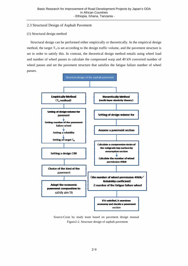
2.3 Structural Design of Asphalt Pavement
(1) Structural design method
Structural design can be performed either empirically or theoretically. In the empirical design
method, the target TA is set according to the design traffic volume, and the pavement structure is
set in order to satisfy this. In contrast, the theoretical design method entails using wheel load
and number of wheel passes to calculate the compressed warp and 49 kN converted number of
wheel passes and set the pavement structure that satisfies the fatigue failure number of wheel
passes.
Source:Creat by study team based on pavement design manual
Figure2-2. Structure design of asphalt pavement

Basic Research for Improvement of Road Development Projects by Japan’s ODA in African Countries
- Ethiopia, Ghana, Tanzania -
2-10
As was mentioned previously, through switching to the performance code, any design method
can be used so long as performance is guaranteed. However, in terms of actual operation, design
based on the TA method is still the mainstream when provisional applications are also included.
Reasons for this are as follows:
The TA method has been devised in consideration of numerous cases and actual
performance in Japan, and it is stable and easy to understand.
There is no method whereby the ordering party can check cross sections designed based on
the multi-layer elasticity theory in the design stage (there is not enough actual experience).
Providing that it is after completion, reverse analysis can be conducted by FWD (Falling
Weight Deflectometer) test, etc.
The scope for setting material conditions (elastic modulus and Poisson’s ratio) used in the
multi-layer elasticity theory is broad, so the validity cannot be confirmed. According to the
actual pavement design execution guidelines too, it “is important to conduct follow-up
survey of post-construction serviceability concerning the permissible scope and width of
these settings.”
Table 2-7. Example of the elastic modulus and
Poissons ratio of materials to use for each pavement layer Material Elastic modulus(MPa) Poissons ratio
Asphalt mixture 600 ~ 12,000 0.25 ~ 0.45
Concrete for pavement
25,000 ~ 35,000 0.15 ~ 0.25
Stabilization with cement
1,000 ~ 15,000 Estimate from compressive strength
0.10 ~ 0.20 0.15 can use as representative value
Gravel material100 ~ 600
Estimate from other dynamic test results
0.25 ~ 0.45 0.35 can use as representative value
Subgrade* 10 x CBR 0.35
*:Reference RR91/243 Department of Transport (South Africa) Source:Creat by study team based on pavement design manual
Since the TA method also includes a lot of empirical elements, in spite of its drawbacks in
that it cannot be immediately applied to new materials (pavement sheet, etc.) and new methods
(composite, etc.), it is likely to remain the mainstream method in Japan for the forseeable future
until enough experience of applying design using multi-layer elasticity theory has been
accumulated.

Basic Research for Improvement of Road Development Projects by Japan’s ODA in African Countries
- Ethiopia, Ghana, Tanzania -
3-1
3. Applicable Standards in the Target Countries 3.1 Applicable Design Standards in the Target Countries
(1) Geometric Structural Standard
Geometric structural standard is a standard for designing roads so that traffic safety and
comfort or the configured service level are satisfied while paying attention to economy. In Japan,
the government order on road design standards prescribes the most important road structure
geometric standards such as road width, building clearance, alignment, visual distance,
intersections and connections, etc. together with the road standard. Moreover, in the target
countries of the study too, the following geometric structural standards, which are similar to
those in the government order on road design standards, exist.
Table 3-1. Geometric structural standard
Target country Japan Ethiopia Ghana Tanzania
Design standard
・Road Structure Ordinance(government ordinance based on the road law) ・A commentary and use Road Structure Ordinance
Geometric Design Manual
Road Design Guide
Draft Road Manual
Origin of publication
・The above is a government ordinance.・"A commentary and the use" are Japan Road Association.
Ethiopian Roads Authority
Ghana Highway Authority
Ministry of Communications
and worksthe year of publication revision 2004 2002 1991 1989
(2) Pavement design standard
The following table indicates the pavement design standards that are used in the target
countries. Concerning Ethiopia and Tanzania, where the specification design method is applied,
because the specifications of used materials are stipulated, it is necessary to confirm by
materials survey that the prescribed materials can be acquired.
Table 3-2. The pavement design method of survey target countries
Target countries Japan Ethiopia Ghana Tanzania
Design standard Pavement Design
Manual (2006,Feb)
Pavement Design Manual 2002 Pavement Design Manual 1998
Pavement and Material Design
Manual 1999 Application
limit (Cumulation
axle load)
― 30 x 106 ― 50 x 106
Design method Performance design method Specification design method Experiential design
method(AASHTO)Specification
design method
Remarks
If it satisfy required performance, it use what kind of design method. For reference, the experiential design method ( TA method), the theoretical design method (Multi layer elastic Analysis) are listed.
During the revision of the standard that out of an application limit to corresponding with the evolution of the pavement technology for the change of social conditions, expansion of the road maintenance, increase of the traffic volume. (Going to publish it as an edition in 2011. Draft version is completed now.)
There is the revision plan of the standard, for new pavment material (modified asphalt) and test method (Superpave,WT examination). It is going to be decided formally by the end of this year
Does not correspond to rigid pavement of the concrete pavement.

Basic Research for Improvement of Road Development Projects by Japan’s ODA in African Countries
- Ethiopia, Ghana, Tanzania -
3-2
(3) Drainage design standards
Pavement drainage is an extremely important factor in pavement design. Because lack of
drainage facilities is one cause of pavement failure, it is important for roads (pavement) to
install appropriate drainage facilities. The following table shows the drainage design standards
that are used in each country.
Table 3-3. Drainage method of survey target countries
Target countries Japan Ethiopia Ghana Tanzania
Design standard Drainage works
Manual 1987(Japan Road Association)
Drainage Design Manual 2002
(Currently revising)
Highway Drainage Manual (Second
Edition) ―
Calculation method of
run-off
① Rational method ① Rational method
② SCS Synthetic Unit Hydrograph
① Rational method
② The Natural Resources and Conservation Service Methods
① Rational method
② The TRRL East African Flood Model
Application of catchment area
Reference of note ① < 0.5km2 ② > 0.5km2
① < 25.0km2 ② > 25.0km2
① < 1.0km2 1.0km2<②
<200km2
Intensity of Rainfall
Drainage works Manual 2-1-2
Short time rainfall of area is shown by a graph in a manual according to the probability year.
Short time rainfall of area(14 area) is shown by a graph in a manual .
About around Dar es Salaam, we can obtain it from the weather station of the Dar es Salaam Airport.
Note
Application of Catchment area is less than about 40km2 . A surface layer condition and the rain condition of the catchment area are available to the same condition, 200 km2 degree.( Technical Criteria for River Works: Practical Guide for Planning) When we use it in the area over 200 km2, it is necessary to be careful.
The rainfall uses a Log PearsonIII type. It is recommended that I calculate rainfallof each probability year. However, it is limited when rain data more than ten years.
Short time reinfall I was shown in "Maximum Rainfall Intensity-Duration Frequencies in Ghana" (1974), and the it were made for about 40 years ago.
East African Flood Model is an effective method in the inland of the East Africa, but there is the opinion that it is not suitable for the use in the coast place with much rainfall.
3.2 Related Survey Standards in the Target Countries
(1) Traffic volume survey
① Ethiopia
The pavement design manual in Ethiopia stipulates that traffic volume survey and axle load
survey be implemented for each project. It stipulates that surveys are conducted seven days
running and that at a 24-hour survey be conducted on at least one day. Moreover, in Ethiopia,
because the traffic volume fluctuates greatly, it is recommended that traffic survey be
implemented a number of times per year. Concerning the axle load survey too, the manual

Basic Research for Improvement of Road Development Projects by Japan’s ODA in African Countries
- Ethiopia, Ghana, Tanzania -
3-3
recommends that it be implemented under the same conditions as the traffic volume survey.
Table 3-4. Standard of the traffic volume survey in Ethiopia
Traffic volume survey
Traffic volume survey of continuation seven days ( at least one day 24 hours) and Axle load survey are carried out several times in a year. It is decided by discussion about the application of axle load of an investigated overloading vehicle.
② Ghana
The pavement design manual in Ghana stipulates that traffic volume survey be implemented
for each project, and that the survey be implemented on a total of three days (12 hours),
specifically two weekdays and one holiday. It has no stipulation concerning axle load survey,
although it requires that the standard car model-separate axle load coefficients indicated in the
design manual are used.
Table 3-5. Standard of the traffic volume survey in Ghana
Traffic volume survey
Traffic volume survey of continuation seven days and Axle load survey of 4 days are carried out. (The seasonal variation uses data of GHA.) It is decided by discussion about the application of axle load of an investigated overloading vehicle.
③ Tanzania
The Field Testing Manual 2003 in Tanzania stipulates that axle load survey and OD survey
be implemented for each project. It requires that the surveys as a rule are implemented 24 hours
a day for seven consecutive days. However, it states no contents concerning seasonal
fluctuations. Concerning the axle load used in design, the manual stipulates that consideration
also be given to overloaded vehicles.
Table 3-6. Standard of the traffic volume survey in Tanzania
Traffic volume survey
Traffic volume survey of continuation seven days(24 hour) are carried out. It prescribes that reflect for a design of axle load of an investigated overloading vehicle
Note When the ratios of the large-sized vehicle(accumulation axle load over 13t) are more than 50%, It will consider a traffic class separately.
(2) Roadbed survey
Concerning survey of roadbed strength too, the standards according to each country’s survey
system are prescribed as follows.
Table 3-7. Subgrade surveyof target survey countries
Turget survey countries
Standard of subgrade strength survey
Ethiopia CBR of laboratory:1 sample/kmSoil test:500m pitch Contents of soil tesr:Consistency limit, grade etc
Ghana
New construction roadLaboratory test:4 sample/km (trunk road) It is reduced the number of the samples in the collector or feeder road Existing road FWD test:Max50m pitch(with DCP)

Basic Research for Improvement of Road Development Projects by Japan’s ODA in African Countries
- Ethiopia, Ghana, Tanzania -
3-4
Tanzania CBR of laboratory:2sample/km(trunk road)、1sample/km(other)、1sample/2km(gravel road)Soil test:4sample/km(trunk road)、2sample/km(other)、2 sample/km(gravel road)
3.3 Asphalt Mix Design
(1) Blend design method for asphalt composite
The target countries use the Marshall test, which is widely used throughout the world, as well
as the following asphalt composite blend design methods.
Table 3-8. Mix design method for asphalt composite
Turget survey countries Blend design method
Ethiopia - Refusal Density
Ghana - Superpave
Tanzania - Refusal Density - Superpave
① Ethiopia
According to the findings of the ERA hearing, use of “Refusal Density” is prescribed
according to categories of traffic volume within the road design standards. The conditions for
applying the “Refusal Density” according to the road design standards are as follows:
- The area concerned is subject to high temperatures.
- The section concerned is used by heavy vehicles.
- Traffic on the section is continuous.
- Heavy vehicles stop and drive slowly on the section.
The following table shows the concrete traffic volume classes for using the refusal density.
Table 3-9. Application condition of Refusal Density(Ethiopia)
Design Traffic (106 ESA)
< 1.5 1.5 - 10.0 > 10.0 Severe Sites
Traffic classes Tl,T2,T3 T4,T5,T6 T7,T8 -
Minimum stability (kN at 600C)
3.5 6.0 7.0 9.0
Minimum flow (mm) 2-4 2-4 2-4 2-4 Compaction level
(Number of blows) 2 x 50 2 x 75 To refusal To refusal
出典:ERA Pavement design manual 2002
However, on checking the actual conditions of use with local consultants, they suggested that
asphalt blending based on refusal density has so far not been actually implemented. Concerning
the reason why, they suggested that because there is no stipulation in the standard works
specification, although it is necessary to make a statement in particular specifications, nobody
until now has compiled particular specifications taking that into consideration.
② Ghana

Basic Research for Improvement of Road Development Projects by Japan’s ODA in African Countries
- Ethiopia, Ghana, Tanzania -
3-5
According to the GHA (Ghana Highway Authority), until now only blend design based on the
Marshall test has been implemented, however, “Superpave” has been used in the recent
Konongo-Kumasi Road rehabilitation project and Route 1 Project (George Bush Highway).
Moreover, the GHA test facility has introduced a gyratory compacter for use with Superpave,
and it has established a setup whereby the GHA itself can conduct tests. At the current time,
there are no clear stipulations concerning the adoption of Marshall test and Superpave, however,
these items will be reflected in revisions of the pavement design standards that are scheduled in
future.
Moreover, in order to confirm the flow-resistance of asphalt, the GHA plans to purchase a
wheel tracking test machine.
③ Tanzania
According to the Central Material Laboratory (CML) of Tanzania, which is a component
organization of TANROADS, blend design based on the Marshall test is common, while the
“Pavement Design Standards” stipulate blend design that uses “Refusal Density” for the
following kinds of roads:
- Uphill roads where the vertical gradient is more than 6%
- Sections where vertical gradient of 4% or more continues for at least 1 km
- Approaches to large intersections
- Routes in all major cities
- Sections of continuous traffic, and areas where vehicles run at low speeds for reasons other
than those stated above
Moreover, Superpave is used in DANIDA projects.

Basic Research for Improvement of Road Development Projects by Japan’s ODA in African Countries
- Ethiopia, Ghana, Tanzania -
4-1
4. Conditions and Causes of Pavement Failure
4.1 Failure Conditions
In hot and humid areas in Africa and Asia, forms of pavement failure that are no longer seen
in Japan are frequently observed on roads that have been constructed under Japanese ODA.
Have such problems been conventionally attributed to improper maintenance, or are there
numerous ways in which design and execution can be improved?
Concerning why such failures do not occur in Japan, the following explanation can be given.
First, on the types of arterial roads on which large size trucks run in Japan, thickness of the
asphalt course including asphalt stabilization reaches 20~30 cm, the roads structurally have
ample durability, modified asphalt is used when the need arises, and maintenance is also carried
out in an organized manner. Meanwhile, in developing countries, the asphalt course is no thicker
than 10 cm, use of modified asphalt is limited, and roads are frequently designed and
constructed without giving adequate consideration to the subbase drainage.
Typical forms of failure in such regions include rutting caused by fluidization of the surface
course, subbase failure caused by the impact of groundwater, and structural failure arising from
insufficient bearing force. (See Photographs 4-1, 4-2 and 4-3).
Photograph 4-1. Groundwater flowing down from the mountain side becomes the pavement failure of the mountain side carriage way. Improvement of the drainage by upsizing of the gutter or the Calvert setting is necessary.
Photograph 4-2. Water in base course is mainly saturated in the sag part of the vertical section, becomes the pavement failure. Damage is seen in both sides across the bridge.
Photograph 4-3. For example rutting caused by fluidization of the surface course. Rrutting is remarkable partly in the steep gradiant section, because run speed becomes the super low speed.

Basic Research for Improvement of Road Development Projects by Japan’s ODA in African Countries
- Ethiopia, Ghana, Tanzania -
4-2
4.2 Projected Causes of Failure
(1) Classification of causes of pavement failure
The causes of pavement failure are often complex in nature and it is extremely difficult to
limit failure to just one cause. For example, rutting can be caused by both internal factors and
external factors. Internal factors are inherent factors in the asphalt mixture itself and include the
quality and quantity of asphalt, type of aggregate, grading and porosity, etc., while external
factors comprise traffic volume, traffic load, temperature, pavement structure and so on. The
following table, which shows the causes of pavement failure, has been compiled in reference to
site surveys, domestic tests and existing literature, etc., although caution is required because it
does not represent all the causes.
Table 4-1. Failure cause of the asphalt pavement (assumption)
Type of failure Main phenomenon (damage) Main origin
Rutting by fluidization
Lateral move of the asphalt mixture
・Excessive traffic volume and traffic load ・Low speed heavy vehicles ・Long-term high temperature ・Mixture defects* ・Construction defects **
Rutting by settlement
Settlement of trace (with Crack)
・Excessive traffic volume and traffic load ・Low speed heavy vehicles ・Bearing capacity shortage of subbase(Problematic soil) ・Influence of the groundwater(Drainage)
Crack Crack of Hexagonal pattern
・Excessive traffic volume and traffic load ・Bearing capacity shortage of subbase and base
course(Drainage) ・Fatigue of the pavement(life) ・Influence of the groundwater(Drainage)
Stripping Stripping of the pavement
・Construction defects ** ・Tack coat defects ・Long-term high temperature ・Thin surfacing ・Influence of excessive external force as hitting
the brakes
Corrugation Ruggedness of such as the wave ・Low speed heavy vehicles ・Mixture defects* ・Construction defects **
Level difference Across the structure ・Construction defects **
Other The loss of a pothole and the
pavement
・Bearing capacity shortage of subbase and base course(Drainage)
・Surface water and groundwater (drainage) ・Behavior of the vehicle
* Mixture defects:Excessive quantity of asphalt,Viscous lack,It is excessive for fine grain,Lack of air void etc. **Construction defects:Poor quality control of the As mixture,Lack of compaction of each pavement
layer,Temperature management,Adhesion failure etc.
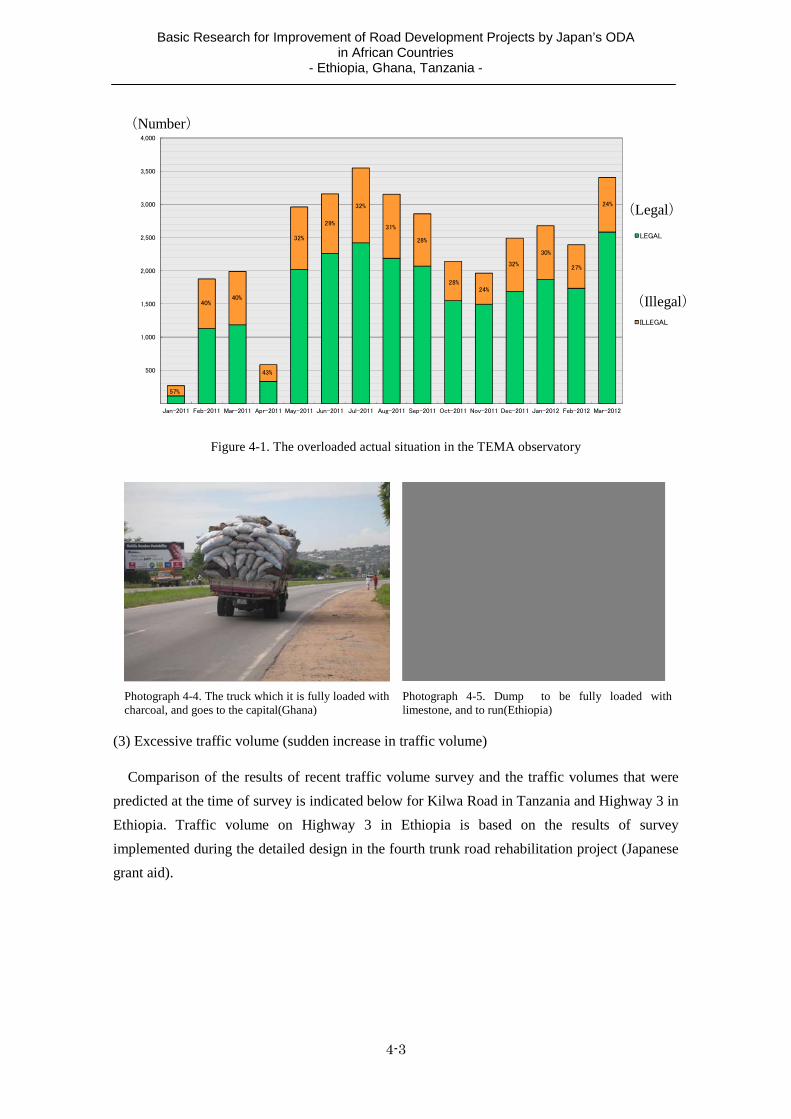
(2) Excessive traffic load (overloading)
In the target countries of the study, vehicle limit values are prescribed under the respective
road traffic laws. Vehicles that go over the load limits are subject to control as overloaded
vehicles. The running of overloaded vehicles is deeply related to failure of paved roads. Figure
4-1 shows the results of aggregating data on overloading obtained from Tema observation point
(National Highway 1) in Ghana. According to this, the ratio of overloaded vehicles in Ghana is
around 30% on average.
Basic Research for Improvement of Road Development Projects by Japan’s ODA in African Countries
- Ethiopia, Ghana, Tanzania -
4-3
500
1,000
1,500
2,000
2,500
3,000
3,500
4,000
Jan-2011 Feb-2011 Mar-2011 Apr-2011 May-2011 Jun-2011 Jul-2011 Aug-2011 Sep-2011 Oct-2011 Nov-2011 Dec-2011 Jan-2012 Feb-2012 Mar-2012
LEGAL
ILLEGAL
57%
40%40%
43%
32%
29%
32%
31%
28%
28%24%
32%
30%
27%
24%
Figure 4-1. The overloaded actual situation in the TEMA observatory
Photograph 4-4. The truck which it is fully loaded with charcoal, and goes to the capital(Ghana)
Photograph 4-5. Dump to be fully loaded with limestone, and to run(Ethiopia)
(3) Excessive traffic volume (sudden increase in traffic volume)
Comparison of the results of recent traffic volume survey and the traffic volumes that were
predicted at the time of survey is indicated below for Kilwa Road in Tanzania and Highway 3 in
Ethiopia. Traffic volume on Highway 3 in Ethiopia is based on the results of survey
implemented during the detailed design in the fourth trunk road rehabilitation project (Japanese
grant aid).
(Number)
(Illegal)
(Legal)
Basic Research for Improvement of Road Development Projects by Japan’s ODA in African Countries
- Ethiopia, Ghana, Tanzania -
4-4
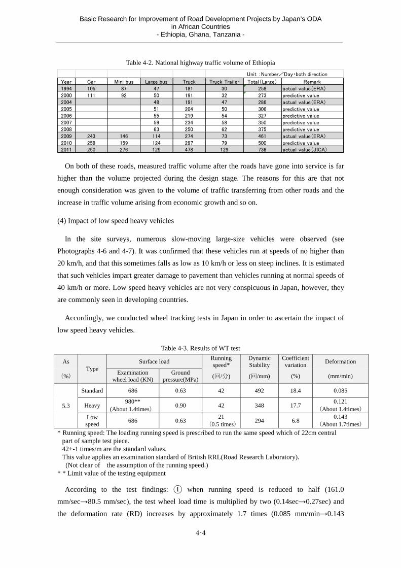
Table 4-2. National highway traffic volume of Ethiopia
Year Car Mini bus Large bus Truck Truck Trailer Total(Large) Remark
1994 105 87 47 181 30 258 actual value(ERA)
2000 111 92 50 191 32 273 predictive value
2004 48 191 47 286 actual value(ERA)
2005 51 204 50 306 predictive value2006 55 219 54 327 predictive value
2007 59 234 58 350 predictive value
2008 63 250 62 375 predictive value
2009 243 146 114 274 73 461 actual value(ERA)
2010 259 159 124 297 79 500 predictive value2011 250 276 129 478 129 736 actual value(JICA)
Unit :Number/Day・both direction
On both of these roads, measured traffic volume after the roads have gone into service is far
higher than the volume projected during the design stage. The reasons for this are that not
enough consideration was given to the volume of traffic transferring from other roads and the
increase in traffic volume arising from economic growth and so on.
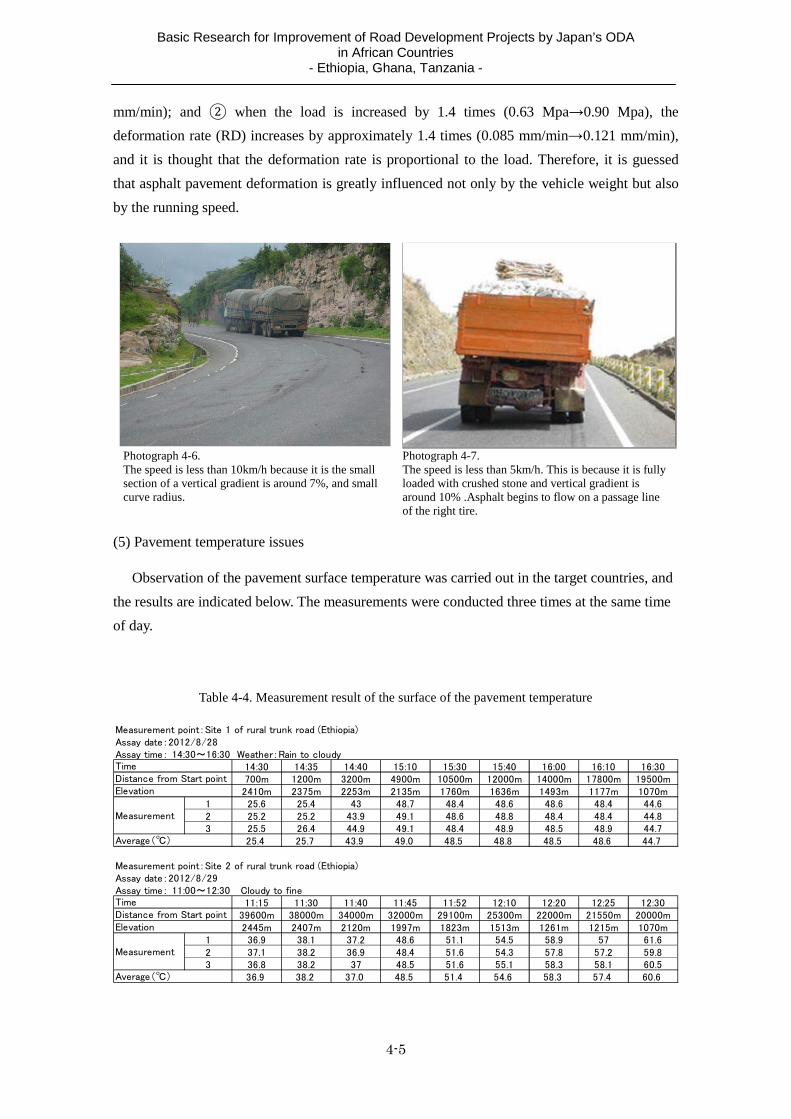
(4) Impact of low speed heavy vehicles
In the site surveys, numerous slow-moving large-size vehicles were observed (see
Photographs 4-6 and 4-7). It was confirmed that these vehicles run at speeds of no higher than
20 km/h, and that this sometimes falls as low as 10 km/h or less on steep inclines. It is estimated
that such vehicles impart greater damage to pavement than vehicles running at normal speeds of
40 km/h or more. Low speed heavy vehicles are not very conspicuous in Japan, however, they
are commonly seen in developing countries.
Accordingly, we conducted wheel tracking tests in Japan in order to ascertain the impact of
low speed heavy vehicles.
Table 4-3. Results of WT test
As Type
Surface load Running speed*
Dynamic Stability
Coefficient variation
Deformation
(%) Examination
wheel load (KN)Ground
pressure(MPa) (回/分) (回/mm) (%) (mm/min)
5.3
Standard 686 0.63 42 492 18.4 0.085
Heavy 980**
(About 1.4times)0.90 42 348 17.7
0.121 (About 1.4times)
Low speed
686 0.63 21
(0.5 times) 294 6.8
0.143 (About 1.7times)
* Running speed: The loading running speed is prescribed to run the same speed which of 22cm central part of sample test piece. 42+-1 times/m are the standard values. This value applies an examination standard of British RRL(Road Research Laboratory). (Not clear of the assumption of the running speed.)
* * Limit value of the testing equipment
According to the test findings: when running speed is reduced to half (161.0
mm/sec 80.5 mm/sec), the test wheel load time is multiplied by two (0.14sec 0.27sec) and
the deformation rate (RD) increases by approximately 1.7 times (0.085 mm/min 0.143
Basic Research for Improvement of Road Development Projects by Japan’s ODA in African Countries
- Ethiopia, Ghana, Tanzania -
4-5
mm/min); and when the load is increased by 1.4 times (0.63 Mpa 0.90 Mpa), the
deformation rate (RD) increases by approximately 1.4 times (0.085 mm/min 0.121 mm/min),
and it is thought that the deformation rate is proportional to the load. Therefore, it is guessed
that asphalt pavement deformation is greatly influenced not only by the vehicle weight but also
by the running speed.
Photograph 4-6. The speed is less than 10km/h because it is the small section of a vertical gradient is around 7%, and small curve radius.
Photograph 4-7. The speed is less than 5km/h. This is because it is fully loaded with crushed stone and vertical gradient is around 10% .Asphalt begins to flow on a passage line of the right tire.
(5) Pavement temperature issues
Observation of the pavement surface temperature was carried out in the target countries, and
the results are indicated below. The measurements were conducted three times at the same time
of day.
Table 4-4. Measurement result of the surface of the pavement temperature
Measurement point:Site 1 of rural trunk road (Ethiopia)Assay date:2012/8/28Assay time: 14:30~16:30 Weather:Rain to cloudy
14:30 14:35 14:40 15:10 15:30 15:40 16:00 16:10 16:30700m 1200m 3200m 4900m 10500m 12000m 14000m 17800m 19500m2410m 2375m 2253m 2135m 1760m 1636m 1493m 1177m 1070m
1 25.6 25.4 43 48.7 48.4 48.6 48.6 48.4 44.62 25.2 25.2 43.9 49.1 48.6 48.8 48.4 48.4 44.83 25.5 26.4 44.9 49.1 48.4 48.9 48.5 48.9 44.7
25.4 25.7 43.9 49.0 48.5 48.8 48.5 48.6 44.7
Measurement point:Site 2 of rural trunk road (Ethiopia)Assay date:2012/8/29
11:15 11:30 11:40 11:45 11:52 12:10 12:20 12:25 12:3039600m 38000m 34000m 32000m 29100m 25300m 22000m 21550m 20000m2445m 2407m 2120m 1997m 1823m 1513m 1261m 1215m 1070m
1 36.9 38.1 37.2 48.6 51.1 54.5 58.9 57 61.62 37.1 38.2 36.9 48.4 51.6 54.3 57.8 57.2 59.83 36.8 38.2 37 48.5 51.6 55.1 58.3 58.1 60.5
36.9 38.2 37.0 48.5 51.4 54.6 58.3 57.4 60.6
Assay time: 11:00~12:30 Cloudy to fineTimeDistance from Start pointElevation
Measurement
Average(℃)
TimeDistance from Start pointElevation
Measurement
Average(℃)

Basic Research for Improvement of Road Development Projects by Japan’s ODA in African Countries
- Ethiopia, Ghana, Tanzania -
4-6
As a result of the measurements, road surface temperatures in excess of 60 were observed
in Ethiopia. In Japan, pavement temperatures in excess of 60 are basically not projected.
(Even the wheel tracking test is conducted at 60 , while temperature in the test machine cannot
be raised to 60 or over).
Concerning the relationship between pavement temperature and strength (DS value) of
asphalt pavement (using straight asphalt), the following relational expression has been obtained
based on wheel tracking tests:
Log10 (DS) = 8.656 – 0.07095T – 0.2285P
DS: Dynamic stability (times/mm) T : Temperature ( ) P : Contact pressure (kgf/cm2)
Source: Q&A on Pavement Technology (Volume 7, top)
A graphic representation on this relational expression is shown in Figure 4-2. According to
this, as opposed to the DS value of 864 times/mm in the regular test temperature (60 ),
strength drops to 382 times/mm (44%) and 382 times/mm (20%) in temperatures of 65 and
70 respectively. This indicates that asphalt pavement becomes more prone to rutting when
there are consecutive days of high temperatures.
22678
10020
4427
1956
864
382
169
1
10
100
1000
10000
100000
30 40 50 60 70 80
回/mm
℃
DS(回/mm)
Figure 4-2. Relations of pavement temperature and the dynamic stability
(6) Grading distribution of aggregate
Trunk road Rehabilitation Project (both grant aid projects of the Japan), unexpectedly early
failure of pavement (mainly flow rutting) was observed. Accordingly, core sampling was
implemented and comparison was carried out on the properties of the asphalt mixture.
The following sections show the grading test results and Superpave control points on both
roads. According to the results, the filler part of both roads (fine particles that pass through a
0.075 mm sieve) shows a fine particle distribution close to the upper value of the control point.
Even in Japan, the amount of aggregate passing through a 2.5 mm sieve is known to have an
(Times/mm) (Times/mm)
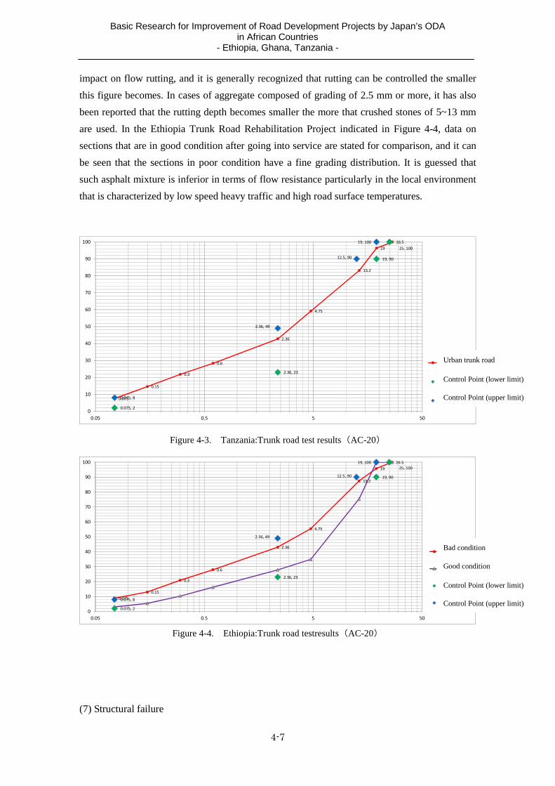
Basic Research for Improvement of Road Development Projects by Japan’s ODA in African Countries
- Ethiopia, Ghana, Tanzania -
4-7
impact on flow rutting, and it is generally recognized that rutting can be controlled the smaller
this figure becomes. In cases of aggregate composed of grading of 2.5 mm or more, it has also
been reported that the rutting depth becomes smaller the more that crushed stones of 5~13 mm
are used. In the Ethiopia Trunk Road Rehabilitation Project indicated in Figure 4-4, data on
sections that are in good condition after going into service are stated for comparison, and it can
be seen that the sections in poor condition have a fine grading distribution. It is guessed that
such asphalt mixture is inferior in terms of flow resistance particularly in the local environment
that is characterized by low speed heavy traffic and high road surface temperatures.
26.5
19
13.2
4.75
2.36
0.6
0.3
0.15
0.075
25, 100
19, 90
2.36, 23
0.075, 2
19, 100
12.5, 90
2.36, 49
0.075, 8
0
10
20
30
40
50
60
70
80
90
100
0.05 0.5 5 50
キルワ道路
制御点(下限)
制御点(上限)
Figure 4-3. Tanzania:Trunk road test results(AC-20)
26.5
19
13.2
4.75
2.36
0.6
0.3
0.15
0.075
25, 100
19, 90
2.36, 23
0.075, 2
19, 100
12.5, 90
2.36, 49
0.075, 8
0
10
20
30
40
50
60
70
80
90
100
0.05 0.5 5 50
状態不良
状態良好
制御点(下限)
制御点(上限)
Figure 4-4. Ethiopia:Trunk road testresults(AC-20)
(7) Structural failure
Urban trunk road
Control Point (upper limit)
Control Point (lower limit)
Control Point (upper limit)
Control Point (lower limit)
Good condition
Bad condition

Basic Research for Improvement of Road Development Projects by Japan’s ODA in African Countries
- Ethiopia, Ghana, Tanzania -
4-8
The photographs indicated below show pavement suffering from structural failure. The cases
shown in Photographs 4-8~10 are caused by poor drainage, those shown in 4-11~12 are caused
by problematic soil (black cotton soil), and that shown in 4-13 is thought to be caused by poor
cohesion between pavement courses.
Photograph4-8. Etiopia:Rural trunk road Pavement was failure because bearing capacity is down by influence of the water at sag point.
Photograph4-9. Etiopia:Rural trunk road Pavement was failure because bearing capacity is down by influence of the groundwater from mountain side.
Photograph4-10. Ghana:Rural trunk road(2007) Intensive section of the surface water
Photograph4-11. Ethiopia:Urban trunk road Under the influence of black cotton soil, Rutting occurred on the surface.
Photograph4-12. Ethiopia:Rural trunk road Typical early case of the pavement failure by black cotton soil(Vertical rutting of pavement edge)
Photograph4-13. Tanzania:Rural trunk road Tack coat defects. Pavement exfoliates for heavy vehicle load

Basic Research for Improvement of Road Development Projects by Japan’s ODA in African Countries
- Ethiopia, Ghana, Tanzania -
4-9
Road drainage is broadly divided into surface drainage and underground drainage. In this
study, as a typical form of pavement failure arising from water, failure caused by groundwater
in cutting sections and around sags was observed in numerous locations. Such failures can be
predicted in advance, and they can be addressed by taking the kind of measures described later
upon conducting economic examination. In addition, another cause of failure is weakening of
the subbase and roadbed arising from surface water flows and inundation in low-lying areas.
Figure 4-15 shows the water flows that have the potential to impact road pavement.
Figure 4-5. Flow of water affecting the pavement
Specifically, there are cases where insufficient depth of side ditches with respect to
groundwater on the highland side causes the groundwater to infiltrate the subbase and weaken it,
cases where rising groundwater level during the rainy season and water flowing inside the
subbase rises in sag sections and thus weakens the subbase, and so forth (see Figure 4-16).
Figure 4-6. Flow of the water at Sag point(Mechanism of the pavement failure)
In the case of subbase, in particular the crusher run, the coefficient of permeability is around
10-3, and if rainwater or groundwater flows into the subbase from outside, it is estimated that the
said water will reach saturation point in a single rainy season1. Because water-saturated
subbases bound by layers with extremely low coefficient of permeability, i.e. asphalt on the top
and roadbed on the bottom, even the smallest amount of deformation caused by surface load
will give rise to a pumping phenomenon whereby the saturated water inside the subbase moves
while dragging particles along. Once small cracks appear on the surface, the pressurized water
1 Assuming that water flows into sags in the road longitudinal direction, in the case of a 5% gradient and coefficient
of permeability of 10-3 (cm/sec), it is possible that the subbase will become saturated over up to 100 m, although this
will also depend on the porosity of the base course.
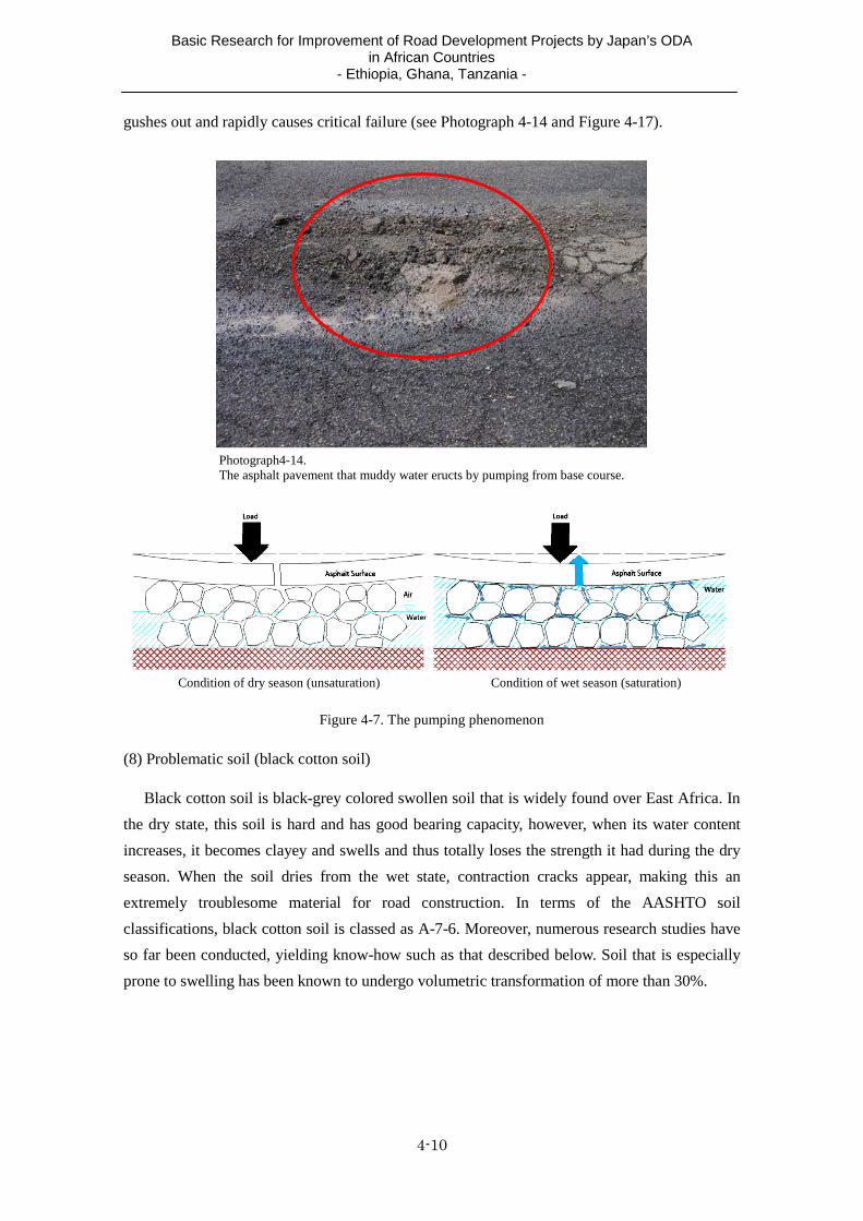
Basic Research for Improvement of Road Development Projects by Japan’s ODA in African Countries
- Ethiopia, Ghana, Tanzania -
4-10
gushes out and rapidly causes critical failure (see Photograph 4-14 and Figure 4-17).
Photograph4-14. The asphalt pavement that muddy water eructs by pumping from base course.
Condition of dry season (unsaturation) Condition of wet season (saturation)
Figure 4-7. The pumping phenomenon
(8) Problematic soil (black cotton soil)
Black cotton soil is black-grey colored swollen soil that is widely found over East Africa. In
the dry state, this soil is hard and has good bearing capacity, however, when its water content
increases, it becomes clayey and swells and thus totally loses the strength it had during the dry
season. When the soil dries from the wet state, contraction cracks appear, making this an
extremely troublesome material for road construction. In terms of the AASHTO soil
classifications, black cotton soil is classed as A-7-6. Moreover, numerous research studies have
so far been conducted, yielding know-how such as that described below. Soil that is especially
prone to swelling has been known to undergo volumetric transformation of more than 30%.

Basic Research for Improvement of Road Development Projects by Japan’s ODA in African Countries
- Ethiopia, Ghana, Tanzania -
4-11
Table 4-6. Possibility of a plasticity index (PI) and the expansion
Possibility of expansion Plasticity index(PI)
Low 0-15 Middle 10-35 High 20-55
Very high >35
Sorce:Trunk road rport of Ethiopia
Table 4-7. Plasticity index (PI) and shrinkage limit and expansion degree
Plasticity index(PI)
Shrinkage limit Rate of changeof the volume
(%)Load:1psi
Expansion degree
>35 <11 >30 Very high 25-41 7-12 20-30 Hign 15-28 10-16 10-30 Middle <18 >15 <10 Low
Sorce:Trunk road report of Ethiopia
Moreover, the form of road failure caused by black cotton soil shows a distinct pattern: first,
vertical cracks appear on the pavement edges and from there the pavement failure spreads.
Photograph4-15. Black cotton soil in Ethiopia Photograph4-16. Black cotton soil(Dry)
Photograph4-17. A test specimen of 20mm of the black cotton soil expands to 35mm 96 hours later(Condition is before immersion in water)

Basic Research for Improvement of Road Development Projects by Japan’s ODA in African Countries
- Ethiopia, Ghana, Tanzania -
4-12
Photograph4-18. Typical early case of the pavement failure by black cotton soil(initial stage)
Photograph4-19. Highway section of the same area as photograph(2010 photography)
(9) Shoulder pavement failure
Failure of shoulder pavement frequently occurs on sections where low-cost pavement is
used for dust control. Particularly in urban and suburban areas where the traffic volume is
heavy, pavement is often damaged when cars try overtaking on the shoulder or enter the road
from the roadside.
Photograph4-20. Parking and stopping of the large car in the shoulder
Photograph4-21. The passing vehicle which running a shoulder.
(10) Knowledge obtained from other site surveys (pavement failure)
Other opinions concerning pavement failure that were obtained in the site survey hearings
are as follows.
・ In light of experience of the early failure of surface course, there is thought to be a
problem with tack coat. In areas of high temperatures, melting of tack coat must be
taken into account.
・ Failure is sometimes caused by inadequate geological survey. Particularly in Dar es
Salaam, since it is possible that valley sections were previously used as waste dumps, it
is important to confirm strength by boring survey in addition to CBR survey.
・ Using good quality materials is the way to ensure the quality of pavement. Specifically,

Basic Research for Improvement of Road Development Projects by Japan’s ODA in African Countries
- Ethiopia, Ghana, Tanzania -
4-13
a lot of failure is caused by using materials with high PI (plasticity index). (The
plasticity index (PI) is an important element in determining the quality of subbase
materials, etc. Generally speaking, deterioration of strength caused by water absorption
is more extreme the higher the plasticity index becomes).
Figure 4-8 Condition of the soil and consistency limit
・ In asphalt mixture, the grading distribution of aggregate often determines the quality of
the mixture.
・ It is important to consider weather conditions when selecting asphalt binder. In areas of
high temperature, consideration should be given to using binder with higher viscosity
(60/70 or 35/50). Also, use of modified asphalt with added polymer should be
considered.(See Table 4-10)
・ In Ghana, GHA (the client) didn’t grant permission to use asphalt binder imported from
a French affiliated petroleum company, citing poor product quality as the reason. This
company also exports asphalt binder to Tanzania.
・ In consultant works supervision, similar to project managers, it is important to assign
experienced materials engineers throughout all processes. Moreover, it is important to
implement stringent process control.
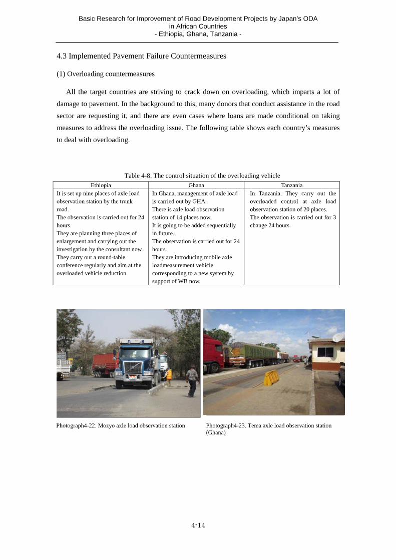
Basic Research for Improvement of Road Development Projects by Japan’s ODA in African Countries
- Ethiopia, Ghana, Tanzania -
4-14
4.3 Implemented Pavement Failure Countermeasures
(1) Overloading countermeasures
All the target countries are striving to crack down on overloading, which imparts a lot of
damage to pavement. In the background to this, many donors that conduct assistance in the road
sector are requesting it, and there are even cases where loans are made conditional on taking
measures to address the overloading issue. The following table shows each country’s measures
to deal with overloading.
Table 4-8. The control situation of the overloading vehicle Ethiopia Ghana Tanzania
It is set up nine places of axle load observation station by the trunk road. The observation is carried out for 24 hours. They are planning three places of enlargement and carrying out the investigation by the consultant now.They carry out a round-table conference regularly and aim at the overloaded vehicle reduction.
In Ghana, management of axle load is carried out by GHA. There is axle load observation station of 14 places now. It is going to be added sequentially in future. The observation is carried out for 24 hours. They are introducing mobile axle loadmeasurement vehicle corresponding to a new system by support of WB now.
In Tanzania, They carry out the overloaded control at axle load observation station of 20 places. The observation is carried out for 3 change 24 hours.
Photograph4-22. Mozyo axle load observation station Photograph4-23. Tema axle load observation station (Ghana)

Basic Research for Improvement of Road Development Projects by Japan’s ODA in African Countries
- Ethiopia, Ghana, Tanzania -
4-15
(2) Failure countermeasures based on pavement type and blend design method
As a result of the site surveys, it was found that modified asphalt (plant mix type) and
concrete pavement are used on important traffic sections in order to boost the fluidity resistance
of asphalt in the target countries.
Table 4-9. Use example of such as the modified asphalt in survey target country
Country Type of pavement Note
Ethiopia
Reinforced concrete pavement
- Bus stop(Japanese grant aid)
- Power station access road (China)
Semi‐flexible pavement
- Parking and stopping area(Japanese grant aid)
Modified Asphalt
- National route 1 project (China)
- Awash Bridge(Japanese grant aid)
The expensive concrete pavement has
not been adopted until recently because
supply of the cement had a problem.
However, three places of cement
factories were built by Chinese fund.
Therefore, supply of the cement was
stable, and an amount of money fell
greatly more.
The adoption of the concrete pavement is
pushed forward from now.
Ghana
Reinforced concrete pavement
- Akura-Tema Road(1964)
- Bus stop on the trunk road
Interlocking pavement
- Point that a large car runs at low speed (Tollgates)
Modified Asphalt
- George Bush HW(MCA)
- Other trunk road
Modified asphalt is used on the main
national highway.
On the George Bush HW (MCA) of ,
Modified asphalt with beads is used.
A major oil company is going to begin
supply of the modified asphalt, and
supply does not have the problem.
Tanzania
Roller compacted concrete pavement(RCCP)
- Tanzam HW(Japanese grant aid)
Modified Asphalt
- Chalinze-Tanga Road(DANIDA)
- Nelson Mandela Road(EU)
- Kilwa Road(Japanese grant aid)
Becausea specialtechniqueis necessary
forrepairas for the concrete pavement
according tothe hearing toTANROAD, it
is difficultto adoptit.
In addition, supply has a problem even if
they adopt concrete pavement because
there is little fee for use of the cement.
(Now building rush, cement is given
priority to big building of the cement fee
for use.)
Photograph4-24. Trunk road (Reinforced concrete pavement)(Ghana)
Photograph4-25. Trunk road:Roller compacted concrete pavement(RCCP)(Tanzania)

Basic Research for Improvement of Road Development Projects by Japan’s ODA in African Countries
- Ethiopia, Ghana, Tanzania -
4-16
Modified asphalt is asphalt in which properties have been improved through adding polymer,
rubber and other modifiers to regular straight asphalt, and using such asphalt makes it possible
to reduce rutting of roads.
RCCP pavement is a type of concrete pavement. Ultra-hard mixed concrete is laid with an
asphalt finisher and compacted by roller compaction. Because reinforcing bars are not used in
this method, work can be executed faster and roads can be opened to traffic quicker than in the
case of regular concrete pavement.
In addition to the above methods for reducing pavement failure based on pavement materials,
there are cases where performance standards are set based on the dynamic stability (DS) (see
Figure 4-10), while there are examples such as Superpave and Refusal Density where measures
are taken based on the blend design. Refusal Density has already been applied in a number of
funded assistance projects.
Table 4-10. The dynamic stability that was used by an expressway project in Ethiopia
Pavement
composition;(Main
line)
Surface corse 4cm:AC-13(50# (40/60)、Modified material for fluidity
resistance)
Base corse 6cm:AC-20 (50# (40/60)、Modified material for fluidity
resistance(Steep gradient section*)
Base : 16cm-17cm:HMAM**-25 (50# (40/60)
Sub-base 32cm:Crushed stone for mechanical stabilization
*Maximum gradient5%
**HMAM: High Module Asphalt Macadam
Use cement concrete pavement at the tollgate.
Method of Mixture
design
Marshall test
The dynamics
examination standard
value(Dynamic
stability)
Unit:times/mm
Surface corse(AC-14) Base corse(AC-20) Base(HMAM)
2800 2800(Modified)
1000(Not modified)
2800
(3) Rutting countermeasures
A common example of failure is rutting caused by fluidization. Assuming areas of high
temperatures, rutting arises from the fluidization of asphalt mixture. Even under the same
temperature and traffic conditions, rutting sometimes occurs in certain areas but not in adjoining
areas for the reasons described below. The recommended countermeasures for such problems
are also described. Out of these factors, the Study Team considers and to be the most
important.

Basic Research for Improvement of Road Development Projects by Japan’s ODA in African Countries
- Ethiopia, Ghana, Tanzania -
4-17
① Inappropriate grading distribution of aggregate … Cases that mainly arise out of quality
control are due to excessive fine particles (2.35 mm or less).
(Countermeasure) Tightening of quality control
② Amount of asphalt, amount of air …This is a design issue. The optimum amount of asphalt
according to the Marshall Law is larger than values obtained from Superpave and Refusal
Density.
(Countermeasure) In the case of asphalt based on the Marshall method, examine the
adoption of Refusal Density. Doing so makes it possible to mesh the aggregate.
The surest way to adjudicate the effects of such measures is to confirm the dynamic
stability (DS) by means of wheel tracking test. In Japan, DS of 3,000 times/mm is adopted
on important traffic routes. In cases where reference values are not satisfied by this test, if
possible it is effective to use plant-type modifier in order to secure the strength of asphalt.
③ Aggregate particle shape issue … There are cases where the round shape of natural sand
aggregate particles is a cause of fluidization. (Countermeasure) Check the shape of sand
particles.
④ Asphalt needle penetration … In areas where the surface temperature is high, if
procurement is possible, it is desirable to adopt low-penetration asphalt upon confirming the
feasibility of execution.
(4) Structural failure countermeasures
In the target countries of the Study, concerning structural failure of pavement, failure caused
by insufficient bearing force due to water inside the subbase was found to be common. In order
to prevent such failure, it is important to prevent rainwater and groundwater from flowing into
the subbase and to expedite the drainage of any water that does flow in. The following
paragraphs describe countermeasures focusing primarily on subbase water drainage. Also, steps
concerning the distinctive black cotton soil of this area are described in section (5).
Generally speaking, groundwater drainage aimed at reducing the groundwater level is
installed in order to prevent weakening of road body, roadbed and subbase. However, in order
to examine underground drainage measures, it is essential to implement groundwater survey at
least two times, once in the rainy season and once in the dry season. According to the results of
hearings with consultants concerning underground drainage facilities in Ethiopia, the following
steps are taken in order to grasp groundwater flows.
・ Information is obtained from local residents and local office employees concerning the
flow trends of rainwater, etc. Also, hydrological engineers conduct site confirmations.
Also, test pits are excavated and boring is conducted if necessary.

Basic Research for Improvement of Road Development Projects by Japan’s ODA in African Countries
- Ethiopia, Ghana, Tanzania -
4-18
Concerning road drainage issues, the concept of subbase drainage is widespread in Western
countries. This method entails using highly permeable subbase materials and using the subbase
as a drainage layer for draining water to the roadside. This subbase drainage method is referred
to as TPB (Treated Permeable Base) and a similar approach is also indicated in the SATCC and
Road Note 31.
Figure 4-9. Design example of the base course drainage in the United States2
In the project (Japanese grant aid) currently being implemented in the target country ,
permeable subbase is extended to the road shoulder with a view to improving the horizontal
drainage efficiency.
Figure 4-10. Change standard typical cross section
2 This is a common practice in the United States. Drainage sewers are installed in cuttings on the mountain side, and banking on the valley side is made by laying subbase materials through the shoulder. (However, in cases where the shoulder is wide or it is desired to achieve certain drainage, sewers are installed in the longitudinal direction on the mountain side too. Incidentally, stabilization of the shoulder materials includes graded crushed stone). In order to effectively facilitate subbase drainage, it is necessary to secure permeable materials such as crusher run or gravel for the base course (usually the lower base course), while drainage to the sides should be installed especially along the longitudinal gradient base (although it is not necessary in all sections). Similar contents are also stated in Japanese road earth and drainage works guidelines.
: Base material : Equal to base material : Sub-base material
Materials application example to a shoulder partType to use base equal materials for the shoulder Merit: It is strong for the water which invaded it within pavement Demerit: Cost is high ①Limitation of the coverage (only sag part) ②When borrow procurement includes limitation, it is effective ③Careful about the water from a gutter of the super elevation

Basic Research for Improvement of Road Development Projects by Japan’s ODA in African Countries
- Ethiopia, Ghana, Tanzania -
4-19
However, in the surveys conducted in both the rainy season and dry season, it was extremely
difficult to fully grasp the actual groundwater conditions, so it is considered more valid to
implement monitoring during the works period while examining countermeasure works.
(5) Countermeasures to problematic soil (black cotton soil) in the target countries
In Ethiopia, black cotton soil is distributed over almost the entire country and is a major
hindrance to road construction. Accordingly, the ERA manual proposes the following
countermeasures: alignment improvement (avoiding areas of black cotton soil),
excavation/soil replacement (replacing black cotton soil with good quality materials along the
road route), limestone stabilization (stabilizing by mixing lime into the black cotton), and
minimization of water content changes (implementing measures to prevent water
infiltration). Out of these, excavation/soil replacement is the most effective method, and it is
recommended that this is applied as much as possible. Table 4-11 shows the black cotton
countermeasures that have been adopted in recently completed projects and projects currently
being implemented.
Table 4-11. Black cotton soil measures example in Ethiopia
Road Control strategy
National road A Replasement 800mm
National road B Replasement 500 – 1500mm Setting of the wall with the low density polyethylene sheet.
National road C Replasement 1000 – 3000mm Reinforcement of the wall with the sheet for block of water.
National road D Replasement 800 – 1500mm
Standard of ERA Replasement of 1,000mm by high quality materials.(more than CBR5) Black cotton soil remained in the lower layer, it take a measures what does not have to change a moisture content.
In Tanzania too, black cotton soil is distributed all over the country and it frequently
becomes a problem in road construction works. Accordingly, black cotton countermeasures are
stipulated in the TANROADS pavement design manual. In the said manual, black cotton soil is
classified according to the coefficient of expansion, and countermeasures are proposed
accordingly.
Table 4-12 shows the countermeasure standards for black cotton soil in different countries.

Basic Research for Improvement of Road Development Projects by Japan’s ODA in African Countries
- Ethiopia, Ghana, Tanzania -
4-20
Table 4-12. Countermeasure standards for black cotton soil in different countries
Target country Recommended measures plan
Zimbabwe Replacement 700mm Kenya Replacement 1000mm
Case study in India Replacement 1000mm SATCC Replacement 1000mm
United States of America Replacement1500mm(Max)
(6) Shoulder pavement measures
Concerning the composition of pavement on road shoulders, the optimum pavement structure
needs to be selected upon considering the transit area (suburban, etc.), the volume of pedestrian
(bicycles) and vehicle traffic, vehicle behavior (shoulder driving or not), and road access from
the roadside and so on. In Ghana, where the study was implemented, an internal notice
recommends that asphalt concrete is used as the shoulder pavement on trunk roads. Meanwhile,
in Tanzania, use of crushed stone shoulder is not recommended on paved roads for the
following reasons:
・ In order to maintain appropriate performance of roads, excessive maintenance is
required.
・ There is greater risk of water flowing into the pavement structure.
・ Unpaved shoulders compromise traffic safety.
・ Height differences between the paved main road and crushed stone shoulders cause
additional risk.

A-1
Annex
Pavement Design Method in Japan (TA method)
This asphalt pavement design method entails stipulating the equivalent converted thickness of
asphalt pavement and ensuring that the converted thickness doesn’t drop below the target even if the
materials used in each course are different. This method has been established as a unique pavement
technology standard in Japan.
This design method was introduced in the Asphalt Pavement Manual that was issued in 1961. It
entails seeking the total thickness of pavement from the daily vehicle traffic volume and design CBR,
and it was developed by Professor Harumi Takeshita when he reworked the CBR design curve of the
American military Corps of Engineers. In 1962, following 10 years of hard work and massive
investment, the AASHO road test results were published. This design method entails seeking the
equivalent converted thickness (TA) from the design CBR and wheel load, and professor Takeshita
reworked the relational expression according to actual conditions in Japan. When the guidelines were
revised in 1967, a design method for seeking the equivalent converted thickness (TA) from the design
wheel load and design CBR was introduced and, because the conventional method for seeking the total
pavement thickness was experiencing no particular problems, this was retained for checking the total
pavement thickness. As a result, the TA-CBR method, which is the core pillar of pavement design in
Japan, was established and it was used up to revision of the guidelines in 1992.
In the guidelines revision of 1992, through prescribing the minimum thickness in each subbase layer,
assuming that balanced pavement composition is adopted, the 4/5H provision (requiring that at least
4/5 of the calculated value is satisfied in the total pavement thickness) was removed, and the currently
used design method based on TA only was adopted. Figure 1 shows the design flow.
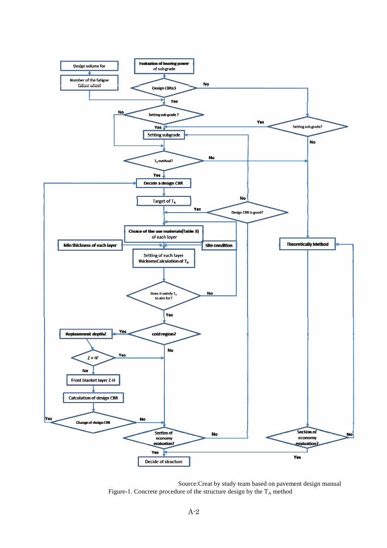
A-2
Source:Creat by study team based on pavement design manual
Figure-1. Concrete procedure of the structure design by the TA method

A-3
1) Number of wheel passes causing fatigue failure
Fatigue failure refers to pavement damage resulting from cracking caused by repeated load, and the
number of wheel passes causing fatigue failure refers to the “number of times required for pavement
cracks to appear when wheel load of 49 kN is repeatedly exerted on the road surface). Standards
figures for the number of number of wheel passes causing fatigue failure are specified as follows
according to the pavement design traffic volume.
Table-1. The number of wheel passes pavement failure
Classification Design daily Volume for pavement*
(unit/day・direction)
Number of wheel passes causing fatigue
failure(times/10 year)
N7 Over 3,000 35,000,000
N6 1,000~3,000 7,000,000
N5 250~1,000 1,000,000
N4 100~250 150,000
N3 40~100 30,000
N2 15~40 7,000
N1 Under 15 1,500
*:Average traffic of the heavy vehicles in the design period of the pavement Source:Manual for Design and Construction of Pavement (Japan Road Association,2006)
Moreover, in cases where the traffic volume and wheel load during the design period are separately
configured, the cumulative 49 kN converted wheel passes are sought using the following expression:
m
ji
jj N
pN
1
4
49 49 )365(
149
n
iiaNN
N49 : 49 kN converted wheel passes per direction per day
Pj : Representative value of wheel load in the scope of wheel load at point J
m : Number of the scope of wheel load (j = 1~m)
Nj : Passing number at Pj
N : Cumulative 49 kN converted wheel passes in the design period, and necessary number of wheel passes
causing fatigue failure
n : Design period
ai : Rate of increase in wheel load passes after “i” years with respect to N49 (i = 1~n)
2) Design in consideration of reliability
With respect to the degree of reliability configured by the road manager, the required equivalent
converted thickness TA is sought from the roadbed design CBR and number of wheel passes causing

A-4
fatigue failure using the following expression. TA indicates the required thickness when pavement is
designed as the surface course and binder course heat asphalt mixture. Reliability is differentiated
according to the status of each road within the network and the importance of each road.
When reliability is 90%: TA=3.84N0.16/CBR0.3
When reliability is 75%: TA=3.43N0.16/CBR0.3
When reliability is 50%: TA=3.07N0.16/CBR0.3
TA : Required equivalent converted thickness
N : Number of wheel passes causing fatigue failure
CBR: Roadbed design CBR
Table -2. Reliability and traffic conversion
Reliability 50% 75% 90%
Mean
Causing fatigue failure term is more than 50% of design period.
Causing fatigue failure term is more than 75% of design period.
Causing fatigue failure term is more than 90% of design period.
Traffic conversion
1 time 2 times 4 times
Term to fatigue failure
The pavement that the fatigue failure does not happen through a design period if it is not change of the design condition
The pavement that fatigue failure does not happen through a design period even if a design condition has some changes. Or the pavement that fatigue failure does not happen even if it exceed design periods a little if it is not change of the design condition
The pavement that fatigue failure does not happen through a design period even if a design condition has a big change. Or the pavement that fatigue failure does not happen even if it largely exceed a design period if it is not change of the design condition
Source:Manual for Design and Construction of Pavement (Japan Road Association,2006)
3) Thickness setting of each course
The thickness of each course is determined in a manner so that the required equivalent converted
thickness TA is not undercut.
Required equivalent converted thickness (TA’) < Required equivalent converted thickness (TA)
i
n
iiA haT
1
'
TA’ : Required equivalent converted thickness (cm)
ai : Equivalent conversion coefficient of materials and methods used in each pavement course (value
indicating 1cm of a pavement course in terms of how many centimeters of surface course and binder
course heated asphalt mixture it corresponds to)
hi : Thickness of each course (cm)

A-5
Table -3. Coefficient of relative strength
Layer Material/Method Quality standard Coefficient of
relative strength
Surface coarse
Base coarse Hot asphalt mixture Use of straight asphalt 1.00
Base
Bituminous stabilization Hot mixing: Stability≧ 3.43kN 0.80
Cold mixing: Stability≧2.45kN 0.55
Cement and bituminous stabilization
Unconfined compression strength 1.5~2.9MPa Quantity of primary displacement 5~30(1/100cm) Residual strength ≧65%
0.65
Cement stabilization Unconfined compression strength [7days] 2.9MPa
0.55
Lime stabilization Unconfined compression strength [10days] 0.98MPa
0.45
Crushed stone for mechanical stabilization Iron and steel slag for mechanical stabilization
Modified CBR ≧80 0.35
Mechanical property of hydraulic, graded iron and steel slag
Modified CBR ≧80 Unconfined compression strength [14days] 1.2MPa
0.55
Sub-base
Crush stone Iron and steel slag Sand
Modified CBR>≧30 0.25
20≦Modified CBR<30 0.20
Cement stabilization Unconfined compression strength [7days] 0.98MPa
0.25
Lime stabilization Unconfined compression strength [10days] 0.7MPa
0.25
Source:Manual for Design and Construction of Pavement (Japan Road Association,2006)
The equivalent conversion coefficients shown in Table 3 represent only those values that are
currently clarified. Concerning other new materials and construction methods, the TA method can be
applied so long as the road manager configures the equivalent conversion coefficient according to the
strength of materials. However, in actual operation, because the test pavement used to determine the
equivalent conversion coefficient incurs a lot of time and cost, a method that entails estimating the
value based on indoor test results (elastic coefficient, etc.) is used. However, since such estimate
values are only provisional, it is still necessary to confirm serviceability by means of test pavement.
Accordingly, a figure of 1.0 is used as the equivalent conversion coefficient of modified asphalt and
semi-flexible pavement, etc.
When determining the thickness of each course, the minimum thicknesses indicated in Tables 4~6
must be satisfied.
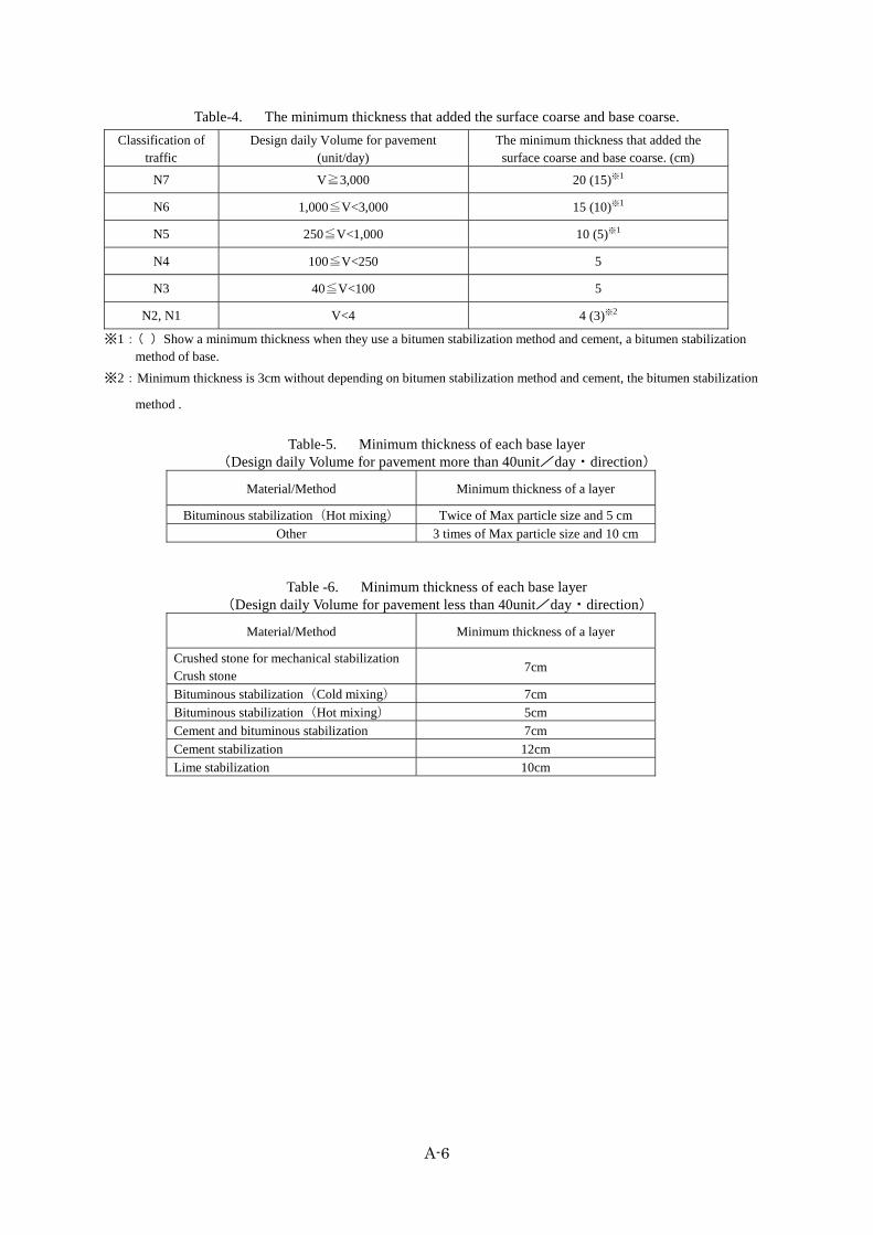
A-6
Table-4. The minimum thickness that added the surface coarse and base coarse.
Classification of traffic
Design daily Volume for pavement (unit/day)
The minimum thickness that added the surface coarse and base coarse. (cm)
N7 V≧3,000 20 (15)※1
N6 1,000≦V<3,000 15 (10)※1
N5 250≦V<1,000 10 (5)※1
N4 100≦V<250 5
N3 40≦V<100 5
N2, N1 V<4 4 (3)※2
※1:( )Show a minimum thickness when they use a bitumen stabilization method and cement, a bitumen stabilization method of base.
※2:Minimum thickness is 3cm without depending on bitumen stabilization method and cement, the bitumen stabilization
method .
Table-5. Minimum thickness of each base layer
(Design daily Volume for pavement more than 40unit/day・direction)
Material/Method Minimum thickness of a layer
Bituminous stabilization(Hot mixing) Twice of Max particle size and 5 cm
Other 3 times of Max particle size and 10 cm
Table -6. Minimum thickness of each base layer (Design daily Volume for pavement less than 40unit/day・direction)
Material/Method Minimum thickness of a layer
Crushed stone for mechanical stabilizationCrush stone
7cm
Bituminous stabilization(Cold mixing) 7cm
Bituminous stabilization(Hot mixing) 5cm
Cement and bituminous stabilization 7cm
Cement stabilization 12cm
Lime stabilization 10cm