basic template for the development of iso and iso/iec ... · 11 separate source ac withstand...
TRANSCRIPT
UGANDA STANDARD
US EAS 371-3
First Edition2006-11-14
Reference numberUS EAS 371-3:2005
© UNBS 2006
Power transformers — Specification — Part 3: Insulation levels, dielectric tests and external clearances in air

US EAS 371-3:2005
© UNBS 2006 ii
Compliance with this standard does not, of itself confer immunity from legal obligations
A Uganda Standard does not purport to include all necessary provisions of a contract. Users are responsible for its correct application
© UNBS 2006
All rights reserved. Unless otherwise specified, no part of this publication may be reproduced or utilised in any form or by any means, electronic or mechanical, including photocopying and microfilm, without prior written permission from UNBS.
Requests for permission to reproduce this document should be addressed to
The Executive Director Uganda National Bureau of Standards P.O. Box 6329 Kampala Uganda Tel: 256 41 505 995 Fax: 256 41 286 123 E-mail: [email protected]

US EAS 371-3:2005
© UNBS 2006 iii
Foreword
Uganda National Bureau of Standards (UNBS) is a parastatal under the Ministry of Tourism, Trade and Industry established, under Cap 327 of the Laws of Uganda. UNBS is mandated to co-ordinate the elaboration of standards and is (a) a member of International Organisation for Standardisation (ISO) and
(b) a contact point for the WHO/FAO Codex Alimentarius Commission on Food Standards, and
(c) the National Enquiry Point on TBT/SPS Agreements of the World Trade Organisation (WTO).
The work of preparing Uganda Standards is carried out through Technical Committees. A Technical Committee is established to deliberate on standards in a given field or area and consists of representatives of consumers, traders, academicians, manufacturers, government and other stakeholders.
Draft Uganda Standards adopted by the Technical Committee are widely circulated to stakeholders and the general public for comments. The committee reviews the comments before recommending the draft standards for approval and declaration as Uganda Standards by the National Standards Council. This Uganda Standard, US EAS 371-3, Power transformers — Specification — Part 3: Insulation levels, dielectric tests and external clearances in air, is identical with and has been reproduced from an East African Standard, EAS 371-3:2005, Power transformers — Specification — Part 3: Insulation levels, dielectric tests and external clearances in air: Temperature rise, and adopted as a Uganda Standard.
For the purpose of this standard, the East African Standard text should be modified as follows:
a) Terminology
The words “this Uganda Standard” should replace the words “this East African Standard” wherever they appear.
b) References
The reference to East African Standards should be replaced by references to the appropriate Uganda Standards where they have been declared.
Committee membership
The following organisations were represented on the Technical Committee on Electrotechnolgy Standards (UNBS/TC 6) in the preparation of this standard:
• Physics Department, Makerere University Kampala – Chairman
• UMEME
• National Environment Management Authority
• Kampala City Traders Association (KACITA)
• Department of Electrical Engineering Kyambogo University
• Mantrac
• ABB Uganda
• Terrain Plant
• Car and General (U) Ltd
• Uganda National Bureau of Standards
EAS 371-3:2005 ICS 29.180
© EAC 2005 First Edition 2005
EAST AFRICAN STANDARD Power transformers — Specification — Part 3: Insulation levels, dielectric tests and external clearances in air
EAST AFRICAN COMMUNITY
EAS 371-3:2005
ii © EAC 2005 — All rights reserved
Foreword Development of the East African Standards has been necessitated by the need for harmonizing requirements governing quality of products and services in East Africa. It is envisaged that through harmonized standardization, trade barriers which are encountered when goods and services are exchanged within the Community will be removed. In order to achieve this objective, the Partner States in the Community through their National Bureaux of Standards, have established an East African Standards Committee.
The Committee is composed of representatives of the National Standards Bodies in Partner States, together with the representatives from the private sectors and consumer organizations. Draft East African Standards are circulated to stakeholders through the National Standards Bodies in the Partner States. The comments received are discussed and incorporated before finalization of standards, in accordance with the procedures of the Community.
East African Standards are subject to review, to keep pace with technological advances. Users of the East African Standards are therefore expected to ensure that they always have the latest versions of the standards they are implementing.
© East African Community 2005 — All rights reserved*
East African Community
P O Box 1096
Arusha
Tanzania
Tel: 255 27 2504253/8
Fax: 255-27-2504481/2504255
E-Mail: [email protected]
Web: www.each.int
*
© 2005 EAC — All rights of exploitation in any form and by any means reserved worldwide for EAC Partner States’ NSBs.
Power transformers –
Part 3:Insulation levels, dielectric tests andexternal clearances in air
Reference numberIEC 60076-3:2000(E)
INTERNATIONALSTANDARD
IEC60076-3
Second edition2000-03
This English-language version is derived from the originalbilingual publication by leaving out all French-languagepages. Missing page numbers correspond to the French-language pages.

Publication numbering
As from 1 January 1997 all IEC publications are issued with a designation in the 60000 series. For example, IEC 34-1 is now referred to as IEC 60034-1.
Consolidated editions
The IEC is now publishing consolidated versions of its publications. For example, edition numbers 1.0, 1.1 and 1.2 refer, respectively, to the base publication, the base publication incorporating amendment 1 and the base publication incorporating amendments 1 and 2.
Further information on IEC publications
The technical content of IEC publications is kept under constant review by the IEC, thus ensuring that the content reflects current technology. Information relating to this publication, including its validity, is available in the IEC Catalogue of publications (see below) in addition to new editions, amendments and corrigenda. Information on the subjects under consideration and work in progress undertaken by the technical committee which has prepared this publication, as well as the list of publications issued, is also available from the following:
• IEC Web Site (www.iec.ch)
• Catalogue of IEC publications
The on-line catalogue on the IEC web site (www.iec.ch/searchpub) enables you to search by a variety of criteria including text searches, technical committees and date of publication. On-line information is also available on recently issued publications, withdrawn and replaced publications, as well as corrigenda.
• IEC Just Published
This summary of recently issued publications (www.iec.ch/online_news/ justpub) is also available by email. Please contact the Customer Service Centre (see below) for further information.
• Customer Service Centre
If you have any questions regarding this publication or need further assistance, please contact the Customer Service Centre:
Email: [email protected] Tel: +41 22 919 02 11 Fax: +41 22 919 03 00
Power transformers –
Part 3:Insulation levels, dielectric tests andexternal clearances in air
For price, see current catalogue
IEC 2000 Copyright - all rights reserved
No part of this publication may be reproduced or utilized in any form or by any means, electronic or mechanical,including photocopying and microfilm, without permission in writing from the publisher.
International Electrotechnical Commission, 3, rue de Varembé, PO Box 131, CH-1211 Geneva 20, SwitzerlandTelephone: +41 22 919 02 11 Telefax: +41 22 919 03 00 E-mail: [email protected] Web: www.iec.ch
INTERNATIONALSTANDARD
IEC60076-3
Second edition2000-03
XACommission Electrotechnique InternationaleInternational Electrotechnical CommissionМеждународная Электротехническая Комиссия
PRICE CODE

60076-3 © IEC:2000 – 3 –
CONTENTS
Page
FOREWORD .......................................................................................................................... 7
INTRODUCTION .................................................................................................................. 11
Clause
1 Scope ............................................................................................................................ 13
2 Normative references ..................................................................................................... 13
3 Definitions...................................................................................................................... 15
4 General .......................................................................................................................... 15
5 Highest voltage for equipment and insulation level .......................................................... 17
6 Rules for some particular transformers ........................................................................... 21
7 Insulation requirements and dielectric tests – Basic rules................................................ 23
7.1 General................................................................................................................. 23
7.2 Insulation requirements ......................................................................................... 25
7.3 Dielectric tests ...................................................................................................... 29
7.4 Insulation requirements and tests for the neutral terminal of a winding ................... 33
8 Tests on a transformer having a tapped winding ............................................................. 35
9 Repeated dielectric tests ................................................................................................ 37
10 Insulation of auxiliary wiring............................................................................................ 37
11 Separate source AC withstand voltage test ..................................................................... 37
12 Induced AC voltage tests (ACSD, ACLD) ........................................................................ 39
12.1 General................................................................................................................. 39
12.2 Short-duration induced AC withstand voltage test (ACSD) for transformerswith uniformly insulated high-voltage windings ....................................................... 39
12.3 Short-duration AC withstand voltage test (ACSD) for transformers withnon-uniformly insulated high-voltage windings ....................................................... 45
12.4 Long-duration induced AC voltage test (ACLD) with non-uniformly and/oruniformly insulated high-voltage windings, according to table 1 .............................. 49
13 Lightning impulse (LI) test .............................................................................................. 55
13.1 General................................................................................................................. 55
13.2 Test sequence ...................................................................................................... 57
13.3 Test connections................................................................................................... 57
13.4 Records of test...................................................................................................... 61
13.5 Test criteria........................................................................................................... 61
14 Test with lightning impulse chopped on the tail (LIC)....................................................... 61
14.1 General................................................................................................................. 61
14.2 Chopping gap and characteristics of the chopping ................................................. 63
14.3 Test sequence and test criteria.............................................................................. 63
60076-3 © IEC:2000 – 5 –
Clause Page
15 Switching impulse test (SI) ............................................................................................. 63
15.1 General................................................................................................................. 63
15.2 Test sequence and records ................................................................................... 65
15.3 Test connections................................................................................................... 65
15.4 Test criteria........................................................................................................... 67
16 External clearances in air ............................................................................................... 67
16.1 General................................................................................................................. 67
16.2 Bushing clearance requirements as determined by transformer insulationwithstand voltages................................................................................................. 69
Annex A (Informative) Application guide for partial discharge measurements duringinduced a.c. withstand voltage test on transformers according to 12.2, 12.3 and 12.4 ............ 85
Annex B (informative) Overvoltage transferred from the high-voltage winding toa low-voltage winding.......................................................................................................... .. 99
Annex C (informative) Information on transformer insulation and dielectric teststo be supplied with an enquiry and with an order ................................................................. 103
Annex D (normative) ACSD .............................................................................................. 105

60076-3 © IEC:2000 – 7 –
INTERNATIONAL ELECTROTECHNICAL COMMISSION____________
POWER TRANSFORMERS –
Part 3: Insulation levels, dielectric tests andexternal clearances in air
FOREWORD
1) The IEC (International Electrotechnical Commission) is a worldwide organization for standardization comprisingall national electrotechnical committees (IEC National Committees). The object of the IEC is to promoteinternational co-operation on all questions concerning standardization in the electrical and electronic fields. Tothis end and in addition to other activities, the IEC publishes International Standards. Their preparation isentrusted to technical committees; any IEC National Committee interested in the subject dealt with mayparticipate in this preparatory work. International, governmental and non-governmental organizations liaisingwith the IEC also participate in this preparation. The IEC collaborates closely with the International Organizationfor Standardization (ISO) in accordance with conditions determined by agreement between the twoorganizations.
2) The formal decisions or agreements of the IEC on technical matters express, as nearly as possible, aninternational consensus of opinion on the relevant subjects since each technical committee has representationfrom all interested National Committees.
3) The documents produced have the form of recommendations for international use and are published in the formof standards, technical specifications, technical reports or guides and they are accepted by the NationalCommittees in that sense.
4) In order to promote international unification, IEC National Committees undertake to apply IEC InternationalStandards transparently to the maximum extent possible in their national and regional standards. Anydivergence between the IEC Standard and the corresponding national or regional standard shall be clearlyindicated in the latter.
5) The IEC provides no marking procedure to indicate its approval and cannot be rendered responsible for anyequipment declared to be in conformity with one of its standards.
6) Attention is drawn to the possibility that some of the elements of this International Standard may be the subjectof patent rights. The IEC shall not be held responsible for identifying any or all such patent rights.
International Standard IEC 60076-3 has been prepared by IEC technical committee 14: Powertransformers.
This second edition cancels and replaces the first edition published in 1980, amendment 1(1981) and IEC 60076-3-1 (1987).
The text of this standard is based on the following documents:
FDIS Report on voting
14/347/FDIS 14/355/RVD
Full information on the voting for the approval of this standard can be found in the report onvoting indicated in the above table.
This publication has been drafted in accordance with the ISO/IEC Directives, Part 3.

60076-3 © IEC:2000 – 9 –
Annexes A, B and C are for information only.
Annex D forms an integral part of this standard.
The committee has decided that the contents of this publication will remain unchangeduntil 2008. At this date, the publication will be
• reconfirmed;
• withdrawn;
• replaced by a revised edition, or
• amended.
The contents of the corrigendum of December 2000 have been included in this copy.

60076-3 © IEC:2000 – 11 –
INTRODUCTION
This part of IEC 60076 specifies the insulation requirements and the corresponding insulationtests with reference to specific windings and their terminals. It also recommends clearances inair between live parts of bushings on oil-immersed power transformers and to objects at earthpotential (clause 16). Guidance can be obtained from IEC 60071.
The insulation levels and dielectric tests which are specified in clauses 4, 5, 6 and 7 in thisstandard apply to the internal insulation only. Whilst it is reasonable that the rated withstandvoltage values which are specified for the internal insulation of the transformer should also betaken as a reference for its external insulation, this may not be true in all cases. A failure of thenon-self-restoring internal insulation is catastrophic and normally leads to the transformerbeing out of service for a long period, while an external flashover may involve only a shortinterruption of service without causing lasting damage. Therefore, it may be that, for increasedsafety, higher test voltages are specified by the purchaser for the internal insulation of thetransformer than for the external insulation of other components in the system. When such adistinction is made, the external clearances must be adjusted to fully cover the internalinsulation test requirements.

60076-3 © IEC:2000 – 13 –
POWER TRANSFORMERS –
Part 3: Insulation levels, dielectric tests andexternal clearances in air
1 Scope
This International Standard applies to single-phase and three-phase oil-immersed powertransformers (including auto-transformers), with the exception of certain small and specialtransformers, as defined in the scope of IEC 60076-1. It identifies transformer windings to theirhighest voltage for equipment Um associated with their corresponding rated insulation levelsand details the relevant applicable dielectric tests and minimum external clearances in airbetween live parts of bushings and to objects at earth potential.
For categories of power transformers and reactors which have their own IEC standards, thisstandard is applicable only to the extent in which it is specifically called up by cross referencein the other standards.
2 Normative references
The following normative documents contain provisions which, through reference in this text,constitute provisions of this part of IEC 60076. For dated references, subsequent amendmentsto, or revisions of, any of these publications do not apply. However, parties to agreementsbased on this part of IEC 60076 are encouraged to investigate the possibility of applying themost recent editions of the normative documents indicated below. For undated references, thelatest edition of the normative document referred to applies. Members of IEC and ISO maintainregisters of currently valid International Standards.
IEC 60050(421), International Electrotechnical Vocabulary (IEV) – Chapter 421: Powertransformers and reactors
IEC 60060-1, High-voltage test techniques – Part 1: General definitions and test requirements
IEC 60060-2, High-voltage test techniques – Part 2: Measuring systems
IEC 60071-1:1993, Insulation coordination – Part 1: Definitions, principles and rules
IEC 60071-2:1976, Insulation coordination – Part 2: Application guide
IEC 60076-1, Power transformers – Part 1: General
IEC 60137:1995, Bushings for alternating voltages above 1 000 V
IEC 60270, Partial discharge measurements
IEC 60722, Guide to the lightning impulse and switching impulse testing of power transformersand reactors

60076-3 © IEC:2000 – 15 –
IEC 60790, Oscilloscopes and peak voltmeters for impulse tests
IEC 61083-1, Digital recorders for measurements in high-voltage impulse tests – Part 1:Requirements for digital recorders
IEC 61083-2, Digital recorders for measurements in high-voltage impulse tests – Part 2:Evaluation of software used for the determination of the parameters of impulse waveforms
CISPR 16-1:1993, Specification for radio disturbance and immunity measuring apparatus andmethods – Part 1: Radio disturbance and immunity measuring apparatus
3 Definitions
For the purpose of this part of IEC 60076, the following definitions apply. Other terms usedhave the meanings ascribed to them in IEC 60076-1 or in IEC 60050(421).
3.1highest voltage for equipment Um applicable to a transformer windingthe highest r.m.s. phase-to-phase voltage in a three-phase system for which a transformerwinding is designed in respect of its insulation
3.2rated insulation levela set of standard withstand voltages which characterize the dielectric strength of the insulation
3.3standard insulation levela rated insulation level, the standard withstand voltages of which are associated to Um asrecommended in tables 2 and 3 of IEC 60071-1
3.4uniform insulation of a transformer windingthe insulation of a transformer winding when all its ends connected to terminals have the samerated insulation level
3.5non-uniform insulation of a transformer windingthe insulation of a transformer winding when it has a neutral terminal end for direct or indirectconnection to earth, and is designed with a lower insulation level than assigned for the lineterminal
4 General
The insulation requirements for power transformers and the corresponding insulation tests aregiven with reference to specific windings and their terminals.
For oil-immersed transformers, the requirements apply to the internal insulation only. Anyadditional requirements or tests regarding external insulation which are deemed necessaryshall be subject to agreement between supplier and purchaser, including type tests on asuitable model of the configuration.

60076-3 © IEC:2000 – 17 –
If the purchaser intends to make the connections to the transformer in a way which may reducethe clearances provided by the transformer alone, this should be indicated in the enquiry.
When an oil-immersed transformer is specified for operation at an altitude higher than 1 000 m,clearances shall be designed accordingly. It may then be necessary to select bushingsdesigned for higher insulation levels than those specified for the internal insulation of thetransformer windings, see clause 16 of this standard and 4.2 of IEC 60137.
Bushings are subject to separate type and routine tests according to IEC 60137, which verifytheir phase-to-earth insulation, external as well as internal.
It is presupposed that bushings and tap-changers are specified, designed and tested inaccordance with relevant IEC standards. The insulation tests on the complete transformer,however, constitute a check on the correct application and installation of these components.
The insulation test shall generally be made at the supplier's works with the transformerapproximately at ambient temperature, but at least at 10 °C.
The transformer shall be completely assembled as in service including supervisory equipment.It is not necessary, however, to fit elements which do not influence the dielectric strength of theinternal insulation, for example, the external cooling equipment.
If a transformer fails to meet its test requirements and the fault is in a bushing, it is permissibleto replace this bushing temporarily with another bushing and continue the test on thetransformer to completion without delay. A particular case arises for tests with partial dischargemeasurements, where certain types of commonly used high-voltage bushings create difficultiesbecause of their relatively high level of partial discharge in the dielectric. When such bushingsare specified by the purchaser, it is permitted to exchange them for bushings of a partialdischarge free type during the testing of the transformer, see annex A.
Transformers for cable box connection or direct connection to metal-enclosed SF6 installationsshould be designed so that temporary connections can be made for insulation tests, usingtemporary bushings, if necessary. By agreement, oil/SF6 bushings may for that reason bereplaced by appropriate oil/air bushings.
When the supplier intends to use non-linear elements or surge arresters, built into thetransformer or externally fitted, for the limitation of transferred overvoltage transients, this shallbe brought to the purchaser's attention at the tender and order stage and it is recommendedthat it be indicated on the transformer rating plate circuit diagram.
5 Highest voltage for equipment and insulation level
To each winding of a transformer, both for the line and neutral side, is assigned a value ofhighest voltage for equipment Um, see 3.1.
The rules for coordination of transformer insulation with respect to transient overvoltages areformulated differently depending on the value of Um.

60076-3 © IEC:2000 – 19 –
When rules about related tests for different windings in a transformer are in conflict, the rule forthe winding with the highest Um value shall apply for the whole transformer.
Rules for a number of special classes of transformers are given in clause 6.
Standardized values of Um are listed in tables 2 to 4. The value to be used for a transformerwinding is the one equal to, or nearest above, the rated value of the winding.
NOTE 1 Single-phase transformers intended for connection in star to form a three-phase bank are designated by
phase-to-earth rated voltage, for example 400/ 3 kV. The phase-to-phase value determines the choice of Um in thiscase, consequently, Um = 420 kV.
NOTE 2 It may happen that certain tapping voltages are chosen slightly higher than a standardized value of Um,but that the system to which the winding will be connected has a system highest voltage which stays within thestandard value. The insulation requirements are to be coordinated with actual conditions, and therefore thisstandard value should be accepted as Um for the transformer, and not the nearest higher value.
NOTE 3 In certain applications with very special conditions the specification of other combinations of withstandvoltages may be justified. In such cases, general guidance should be obtained from IEC 60071-1.
NOTE 4 In certain applications, delta-connected windings are earthed through one of the external terminals. Inthose applications, a higher withstand voltage with respect to the highest voltage for equipment Um may be requiredfor this winding and should be agreed between supplier and purchaser.
The highest voltage for equipment Um and its assigned withstand voltages, that is, theirinsulation level, determine the dielectric characteristics of a transformer. They are verified by aset of dielectric tests depending on Um, see clause 7.
The value of Um and the insulation level which are assigned to each winding of a transformerare part of the information to be supplied with an enquiry and with an order. If there is awinding with non-uniform insulation, the assigned Um and the insulation level of the neutralterminal shall also be specified by the purchaser, see 7.4.3.
The rated withstand voltages for all windings shall appear on the rating plate. The principles ofthe standard abbreviated notation are shown in some examples below.
The classifications on the insulation design shall independently of the test procedure bederived from the values in table 2, 3 and 4 or from IEC 60071-1. Since in most cases the long-duration induced AC tests are quality control tests in respect to service conditions and notdesign proving tests, the insulation level shall be characterized as follows:
Um is the highest voltage for equipmentSI/LI/AC,
where applicable –/LI/AC.
The abbreviations here and in the examples below have the following meaning:
SI is the switching impulse withstand voltage for the line terminals of the winding with thehighest Um;
LI is the lightning impulse withstand voltage for the line and neutral terminals of eachindividual winding;
AC is the short duration induced and separate source AC withstand voltage for the line andneutral terminals of each individual winding;
h.v. high voltage;
l.v. low voltage;
m.v. medium voltage.

60076-3 © IEC:2000 – 21 –
Example 1:
Um (h.v.) = 72,5 kV and Um (l.v.) = 12 kV, both uniformly insulated, Y connected
Insulation levels: h.v. line terminal and neutral LI/AC 325/140 kV
l.v. line terminal and neutral LI/AC 60/28 kV
Example 2:
Um (h.v.) line = 245 kV, Y connected;
Um (h.v.) neutral = 52 kV;
Um (m.v.) line = 72,5 kV, uniform insulation, Y connected;
Um (l.v.) line = 24 kV, D connected.
Insulation levels: h.v. line terminal SI/LI 650/850 kV
h.v. neutral LI/AC 250/95 kV
m.v. line terminal and neutral LI/AC 325/140 kV
l.v. line terminal LI/AC 125/50 kV
Example 3:
Auto-transformer with Um = 420 kV and 145 kV with an assigned Um = 17,5 kV for the neutralfor direct earth connection, Y connected. Um (l.v.) line terminal = 24 kV, D connected.
Insulation levels: h.v. line terminal SI/LI 1 050/1 300 kV
m.v. line terminal LI/AC 550/230 kV
h.v./m.v.-neutral LI/AC –/38 kV
l.v. line terminal LI/AC 125/50 kV
or if additionally a short-duration induced test is required:
Insulation levels: h.v. line terminal SI/LI/AC 1 050/1 300/570 kV
m.v. line terminal LI/AC 550/230 kV
h.v./m.v. neutral LI/AC –/38 kV
l.v. line terminal LI/AC 125/50 kV
6 Rules for some particular transformers
In transformers where uniformly insulated windings having different Um values are connectedtogether within the transformer (usually auto-transformers), the separate source AC withstandtest voltages shall be determined by the insulation of the common neutral and its assigned Um.
In transformers which have one or more non-uniformly insulated windings, the test voltages forthe induced withstand voltage test, and for the switching impulse test if used, are determinedby the winding with the highest Um value, and the windings with lower Um values may notreceive their appropriate test voltages. This discrepancy should normally be accepted. If theratio between the windings is variable by tappings, this should be used to bring the test voltagefor the winding with lower Um voltage as close as possible to the appropriate value.

60076-3 © IEC:2000 – 23 –
During switching impulse tests, the voltages developed across different windings areapproximately proportional to the ratio of numbers of turns. Rated switching impulse withstandvoltages shall only be assigned to the winding with the highest Um. Test stresses in otherwindings are also proportional to the ratio of numbers of turns and are adjusted by selectingappropriate tappings to come as close as possible to the assigned value in table 4. Theswitching impulse test stresses in other windings shall be limited to approximately 80 % of theassigned lightning impulse withstand voltages at these terminals.
Series windings in booster regulating transformers, phase shifting transformers, etc. where therated voltage of the winding is only a small fraction of the voltage of the system, shall have avalue of Um corresponding to the system voltage. It is often impracticable to test such trans-formers in formal compliance with this standard, and it should be agreed between the supplierand the purchaser as to which tests have to be omitted or modified.
For single-phase transformers intended to be connected between phases, as in the case ofrailway traction system supplies, higher test values than indicated in this standard may benecessary.
Special considerations with respect to test connections and number of tests to be performed onmultiple re-connectable transformers shall be agreed at the time of placing the order.
7 Insulation requirements and dielectric tests – Basic rules
Transformer windings are identified by their highest voltage for equipment Um associated totheir corresponding insulation levels. This clause details the relevant insulation requirementsand applicable dielectric tests. For categories of power transformers and reactors which havetheir own IEC standards, the requirements are applicable only to the extent in which they arespecifically called up by cross reference in the other standards.
7.1 General
The basic rules for insulation requirements and dielectric tests are summarized in table 1.
Levels of standard withstand voltages, identified by the highest voltage for equipment Um of awinding are given in tables 2, 3 and 4. The choice between the different levels of standardwithstand voltages in these tables depends on the severity of overvoltage conditions to beexpected in the system and on the importance of the particular installation. Guidance may beobtained from IEC 60071-1.
NOTE 1 Distribution transformers for suburban or rural installation are, in some countries, severely exposed toovervoltages. In such cases, higher test voltages, lightning impulse tests and other tests on individual units may beagreed between supplier and purchaser. They should be clearly stated in the enquiry document.
NOTE 2 Other combinations of Um may exist in some countries.
Information about the selected transformer insulation requirements and dielectric tests shall besupplied with an enquiry and with an order, see annex C.
The insulation requirements are specified in 7.2. The verification of the withstand voltages bydielectric tests is given in 7.3. The insulation requirements and tests for the neutral terminal ofa winding are given in 7.4.
60076-3 © IEC:2000 – 25 –
The extension of the lightning impulse test to include impulses chopped on the tail as a specialtest is recommended in cases where the transformer is directly connected to GIS by means ofoil/SF6 bushings or when the transformer is protected by rod gaps. The peak value of thechopped impulse shall be 10 % higher than for the full impulse.
For transformers with a high-voltage winding having Um > 72,5 kV, lightning impulse tests areroutine tests for all windings of the transformer.
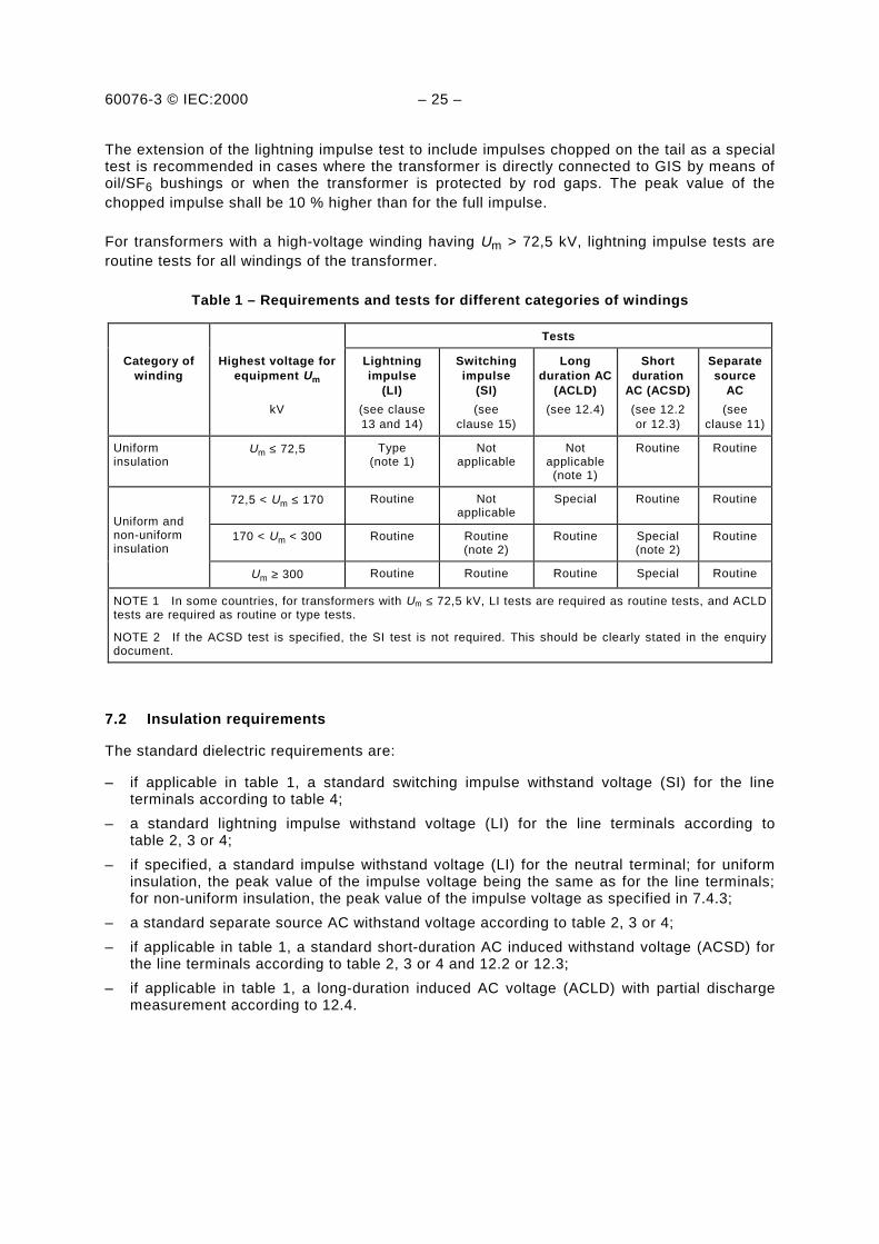
Table 1 – Requirements and tests for different categories of windings
Tests
Category ofwinding
Highest voltage forequipment Um
kV
Lightningimpulse
(LI)
(see clause13 and 14)
Switchingimpulse
(SI)
(seeclause 15)
Longduration AC
(ACLD)
(see 12.4)
Shortduration
AC (ACSD)
(see 12.2or 12.3)
Separatesource
AC
(seeclause 11)
Uniforminsulation
Um ≤ 72,5 Type(note 1)
Notapplicable
Notapplicable
(note 1)
Routine Routine
72,5 < Um ≤ 170 Routine Notapplicable
Special Routine Routine
Uniform andnon-uniforminsulation
170 < Um < 300 Routine Routine(note 2)
Routine Special(note 2)
Routine
Um ≥ 300 Routine Routine Routine Special Routine
NOTE 1 In some countries, for transformers with Um ≤ 72,5 kV, LI tests are required as routine tests, and ACLDtests are required as routine or type tests.
NOTE 2 If the ACSD test is specified, the SI test is not required. This should be clearly stated in the enquirydocument.
7.2 Insulation requirements
The standard dielectric requirements are:
– if applicable in table 1, a standard switching impulse withstand voltage (SI) for the lineterminals according to table 4;
– a standard lightning impulse withstand voltage (LI) for the line terminals according totable 2, 3 or 4;
– if specified, a standard impulse withstand voltage (LI) for the neutral terminal; for uniforminsulation, the peak value of the impulse voltage being the same as for the line terminals;for non-uniform insulation, the peak value of the impulse voltage as specified in 7.4.3;
– a standard separate source AC withstand voltage according to table 2, 3 or 4;
– if applicable in table 1, a standard short-duration AC induced withstand voltage (ACSD) forthe line terminals according to table 2, 3 or 4 and 12.2 or 12.3;
– if applicable in table 1, a long-duration induced AC voltage (ACLD) with partial dischargemeasurement according to 12.4.

60076-3 © IEC:2000 – 27 –
Table 2 – Rated withstand voltages for transformer windings withhighest voltage for equipment Um ≤ 170 kV –
Series I based on European practice
Highest voltage forequipment Um
kV r.m.s.
Rated lightningimpulse withstand
voltage
kV peak
Rated short durationinduced or separate source
AC withstand voltage
kV r.m.s.
203,6 10
407,2 20
6012 28
7517,5 38
9524 50
125
14536 70
170
52 250 95
60 280 115
72,5 325 140
380 150100
450 185123
550 230145
650 275170
750 325
NOTE Dotted lines may require additional phase-to-phase withstand tests to provethat the required phase-to-phase withstand voltages are met.
Low-voltage windings with Um ≤ 1,1 kV shall be tested with 3 kV separate source AC withstandvoltage.

60076-3 © IEC:2000 – 29 –
7.3 Dielectric tests
The standard dielectric requirements are verified by dielectric tests. They shall, whereapplicable and not otherwise agreed upon, be performed in the sequence as given below.
– Switching impulse test (SI) for the line terminal, see clause 15
The test is intended to verify the switching impulse withstand strength of the line terminalsand its connected winding(s) to earth and other windings, the withstand strength betweenphases and along the winding(s) under test.
The test is an essential requirement for transformers subjected to a long-duration inducedAC withstand voltage (ACLD) test.
– Lightning impulse test (LI) for the line terminals, see clause 13
The test is intended to verify the impulse withstand strength of the transformer under test,when the impulse is applied to its line terminals. If the lightning impulse test includesimpulses chopped on the tail (LIC), the impulse test is modified according to clause 14.
– Lightning impulse test (LI) for the neutral terminal, see 13.3.2
The test is intended to verify the impulse withstand voltage of the neutral terminal and itsconnected winding(s) to earth and other windings, and along the winding(s) under test.
This test is required if a standard impulse withstand voltage for the neutral is specified.
– Separate source AC withstand voltage test (applied potential test), see clause 11
The test is intended to verify the AC withstand strength of the line and neutral terminals andtheir connected windings to earth and other windings.
– Short-duration induced AC withstand voltage test (ACSD), see 12.2 and 12.3
The test is intended to verify the AC withstand strength of each line terminal and itsconnected winding(s) to earth and other windings, the withstand strength between phasesand along the winding(s) under test.
The test shall be performed in accordance with 12.2 for uniform insulation and 12.3 for non-uniform insulation.
For Um > 72,5 kV, the test is normally performed with partial discharge measurements toverify partial discharge free operation of the transformer under operating conditions. Byagreement between supplier and purchaser, the partial discharge measurements may alsobe performed for Um ≤ 72,5 kV.
– Long-duration induced AC voltage test (ACLD), see 12.4
This test is not a design proving test, but a quality control test, and is intended to covertemporary overvoltages and continuous service stress. It verifies partial discharge-freeoperation of the transformer under operating conditions.

60076-3 © IEC:2000 – 31 –
Table 3 – Rated withstand voltages for transformer windingswith highest voltage for equipment Um ≤ 169 kV –
Series II based on North American practice
Rated lightning impulsewithstand voltage
kV peak
Rated short-duration induced orseparate source ACwithstand voltage
kV r.m.s.
Highest voltagefor
equipment Um
kV r.m.s.
Distribution (note 1)and class I
transformers(note 2)
Class IItransformers
(note 3)
Distribution andclass I
transformers
Class IItransformers
15
26,4
36,5
48,3
72,5
121
145
169
95
125
150
200
250
350
110
–
150
200
250
350
350
450
550
650
750
34
40
50
70
95
140
34
–
50
70
95
140
140
185
230
275
325
NOTE 1 Distribution transformers transfer electrical energy from a primary distribution circuit to a secondarydistribution circuit.
NOTE 2 Class I power transformers include high-voltage windings of Um ≤ 72,5 kV.
NOTE 3 Class II power transformers include high-voltage windings of Um ≥ 121 kV.

60076-3 © IEC:2000 – 33 –
Table 4 – Rated withstand voltages for transformer windingswith Um > 170 kV
Highest voltage forequipment Um
kV r.m.s
Rated switching impulsewithstand voltage
phase-to-earth
kV peak
Rated lightning impulsewithstand voltage
kV peak
Rated short-durationinduced or separatesource AC withstand
voltagekV r.m.s.
245
300
362
420
550
800
550
650
750
850
950
850
950
1050
1175
1300
1300
1425
1550
650
750
850
950
1050
1175
1050
1175
1300
1425
1550
1675
1800
1950
2100
325
360
395
460
510
460
510
570
630
680
note 3
note 3
note 3
NOTE 1 Dotted lines are not in line with IEC 60071-1 but are current practice in some countries.
NOTE 2 For uniformly insulated transformers with extremely low values of rated AC insulation levels, specialmeasures may have to be taken to perform the short-duration AC induced test, see 12.2.
NOTE 3 Not applicable, unless otherwise agreed.
NOTE 4 For voltages given in the last column, higher test voltages may be required to prove that the requiredphase-to-phase withstand voltages are met. This is valid for the lower insulation levels assigned to thedifferent Um in the table.
7.4 Insulation requirements and tests for the neutral terminal of a winding
7.4.1 General
The necessary insulation level depends on whether or not the neutral terminal is intended to bedirectly earthed, left open or earthed via an impedance. When the neutral terminal is notdirectly earthed, an overvoltage protective device should be installed between the neutralterminal and earth in order to limit transient voltages.
NOTE The recommendations below deal with the determination of the necessary minimum withstand voltage forthe neutral terminal. An increase of the value may sometimes easily be arranged and can improve theinterchangeability of the transformer in the system. For non-uniform insulation it may be necessary to design thewinding with higher neutral insulation level because of the test connection to be used for the AC withstand test ofthe transformer, see 12.3.

60076-3 © IEC:2000 – 35 –
7.4.2 Directly earthed neutral terminal
The neutral terminal shall be permanently connected to earth, directly or through a currenttransformer, but without any intentionally added impedance in the connection.
In this case, the separate source AC withstand voltage shall be at least either 38 kV (Europeanpractice) or 34 kV (North American practice).
No impulse test on the neutral terminal is recommended. During impulse tests on a lineterminal, the neutral shall be connected directly to earth.
7.4.3 Neutral terminal not directly earthed
The neutral terminal is not to be permanently in direct connection to earth. It may be connectedto earth through a considerable impedance (for example arc-suppression coil earthing).Separate phase-winding neutral terminals may be connected to a regulating transformer.
It is the responsibility of the purchaser to select the overvoltage protective device, to determineits impulse protection level, and to specify the corresponding impulse withstand voltage for theneutral terminal of the transformer. A suitable Um shall be assigned for the neutral and shall beselected from table 2, 3 or 4, and the corresponding rated separate source AC withstandvoltage from the table shall apply. The AC withstand voltage should be greater than themaximum overvoltage arising under system fault conditions.
The rated impulse withstand voltage of the neutral terminal shall be verified by either of the twotests described in 13.3.2. A chopped wave impulse test on the neutral is not applicable. Fortransformers having a tapped winding near the neutral end of the winding, the tappingconnection with the maximum turns ratio shall be chosen for the impulse test, if not otherwiseagreed between purchaser and supplier.
8 Tests on a transformer having a tapped winding
If the tapping range is ±5 % or less, the dielectric tests shall be done with the transformerconnected on the principal tapping.
If the tapping range is larger than ±5 %, the choice of tapping cannot be prescribed universallyand the following applies.
Testing conditions determine the choice of tapping required for the induced AC test and for theswitching impulse test (SI), see clause 6.
Under lightning impulse test (LI) the dielectric stresses are distributed differently depending onthe tapping connection and the general design of the transformer. Unless impulse testing on aparticular tapping has been agreed, the two extreme tappings and the principal tapping shall beused, one tapping for each of the three individual phases of a three-phase transformer or thethree single-phase transformers designed to form a three-phase bank. For an impulse test onthe neutral terminal, see 7.4.3.

60076-3 © IEC:2000 – 37 –
9 Repeated dielectric tests
For transformers which have already been in service and have been refurbished or serviced,dielectric tests according to 7.2, 7.3 and 7.4 shall be repeated at test levels of 80 % of theoriginal values, unless otherwise agreed upon, and provided that the internal insulation has notbeen modified. Long-duration AC induced tests (ACLD) according to 12.4 shall always berepeated at 100 % test level.
NOTE The partial discharge criteria should be discussed between the purchaser and supplier depending on theextent of the repair.
Repetition of tests required to prove that new transformers, having been factory tested to 7.2,7.3 and 7.4, continue to meet the requirements of this standard is always performed at 100 %of test level.
10 Insulation of auxiliary wiring
The wiring for auxiliary power and control circuitry shall be subjected to a 1 min AC separatesource test of 2 kV r.m.s. to earth, unless otherwise specified. Motors and other apparatus forauxiliary equipment shall fulfil insulation requirements according to the relevant IEC standard(which are generally lower than the value specified for the wiring alone, and which maysometimes make it necessary to disconnect them in order to test the circuits).
NOTE Auxiliary equipment for large transformers is usually dismantled for shipment. After completion of erectionon site, a 1 000 V megaohm meter test is recommended. Any electronic equipment with a withstand voltage lessthan 1 000 V should be removed prior to this test.
11 Separate source AC withstand voltage test
The separate source AC voltage test shall be made with single-phase alternating voltage asnearly as possible on sine-wave form and not less than 80 % of the rated frequency.
The peak value of voltage shall be measured. The peak value divided by 2 shall be equal tothe test value.
The test shall commence at a voltage not greater than one-third of the specified test value, andthe voltage shall be increased to the test value as rapidly as is consistent with measurement.At the end of the test, the voltage shall be reduced rapidly to less than one-third of the testvalue before switching off. On windings with non-uniform insulation, the test is carried out withthe test voltage specified for the neutral terminal. The line terminals are then subjected to anAC induced withstand voltage test according to 12.3 or 12.4.
The full test voltage shall be applied for 60 s between all terminals of the winding under testconnected together and all terminals of the remaining windings, core, frame and tank or casingof the transformer, connected together to earth.
The test is successful if no collapse of the test voltage occurs.

60076-3 © IEC:2000 – 39 –
12 Induced AC voltage tests (ACSD, ACLD)
12.1 General
Subclauses 12.2 and 12.3 refer to the short-duration induced AC withstand tests (ACSD) foruniform and non-uniform insulation. For Um > 72,5 kV, the ACSD test is normally performedwith partial discharge measurements. The measurements of partial discharge during the wholeapplication of the test is a valuable tool for the supplier as well as for the purchaser. Measuringpartial discharges during the test may indicate an insulation deficiency before breakdownoccurs. The test verifies partial discharge-free operation of the transformer during operatingconditions.
The requirements for partial discharge measurement during the ACSD test may be omitted.This shall be clearly stated at the enquiry and order stages.
Subclause 12.4 refers to the long-duration induced AC voltage test (ACLD) for uniform andnon-uniform insulation. This test is always performed with the measurement of partialdischarges during the whole application of the test.
An alternating voltage shall be applied to the terminals of one winding of the transformer. Theform of the voltage shall be as nearly as possible sinusoidal and its frequency shall besufficiently above the rated frequency to avoid excessive magnetizing current during the test.
The peak value of the induced test voltage shall be measured. The peak value divided
by 2 shall be equal to the test value.
The test time at full test voltage shall be 60 s for any test frequency up to and including twicethe rated frequency, unless otherwise specified. When the test frequency exceeds twice therated frequency, the test time in seconds of the test shall be:
frequencytest
frequencyrated120 × , but not less than 15 s
12.2 Short-duration induced AC withstand voltage test (ACSD) for transformers withuniformly insulated high-voltage windings
All three-phase transformers shall be tested with a symmetrical three-phase supply. If atransformer has a neutral, it should be earthed during the test. On transformers with uniformlyinsulated windings, only phase-to-phase tests are carried out. Phase-to-earth tests are coveredby separate source AC tests according to clause 11.
Dependant on the highest voltage for equipment Um, the test shall be carried out accordingto 12.2.1 or 12.2.2.
12.2.1 Transformers with Um ≤ 72,5 kV
The phase-to-phase test voltage shall not exceed the rated induced AC withstand voltages intables 2 or 3. As a rule, the test voltage accross an untapped winding of the transformer shallbe as close as possible to twice the rated voltage. Normally, no partial discharge measure-ments are performed during this test.

60076-3 © IEC:2000 – 41 –
The test shall be commenced at a voltage not greater than one-third of the test value and thevoltage shall be increased to the test value as rapidly as is consistent with measurement. Atthe end of the test, the voltage shall be reduced rapidly to less than one-third of the test valuebefore switching off.
The test is successful if no collapse of the test voltage occurs.
12.2.2 Transformers with Um > 72,5 kV
These transformers shall all, if not otherwise agreed, be tested with partial dischargemeasurement. The phase-to-phase test voltages shall not exceed the rated AC withstandvoltages of tables 2, 3 or 4. As a rule, the test voltage across an untapped winding of thetransformer shall be as close as possible to twice the rated voltage.
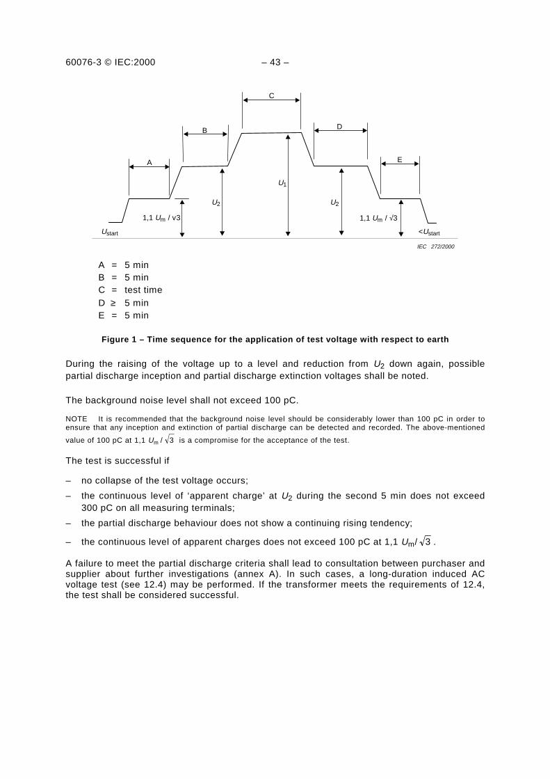
The partial discharge performance shall be controlled according to the time sequence for theapplication of the voltage as shown in figure 1.
In order not to exceed the rated withstand voltage between phases according to tables 2, 3and 4, the partial discharge evaluation level U2 shall be:
1,3 Um / 3 phase-to-earth and
1,3 Um phase-to-phase
Annex D, table D.1 shows both the test voltages U1 obtained from tables 2 or 4 and appropriatevalues of U2.
The voltage with respect to earth shall be:
– switched on at a level not higher than one-third of U2;
– raised to 1,1 Um / 3 and held there for a duration of 5 min;
– raised to U2 and held there for a duration of 5 min;
– raised to U1, held there for the test time as stated in 12.1;
– immediately after the test time, reduced without interruption to U2 and held there for aduration of at least 5 min to measure partial discharges;
– reduced to 1,1 Um / 3 and held there for a duration of 5 min;
– reduced to a value below one-third of U2 before switching off.
60076-3 © IEC:2000 – 43 –
Ustart
A
B
C
D
E
1,1 Um / v3
U2
U1
U2
1,1 Um / √3
<Ustart
IEC 272/2000
A = 5 minB = 5 minC = test timeD ≥ 5 minE = 5 min
Figure 1 – Time sequence for the application of test voltage with respect to earth
During the raising of the voltage up to a level and reduction from U2 down again, possiblepartial discharge inception and partial discharge extinction voltages shall be noted.
The background noise level shall not exceed 100 pC.
NOTE It is recommended that the background noise level should be considerably lower than 100 pC in order toensure that any inception and extinction of partial discharge can be detected and recorded. The above-mentioned
value of 100 pC at 1,1 Um / 3 is a compromise for the acceptance of the test.
The test is successful if
– no collapse of the test voltage occurs;
– the continuous level of ‘apparent charge’ at U2 during the second 5 min does not exceed300 pC on all measuring terminals;
– the partial discharge behaviour does not show a continuing rising tendency;
– the continuous level of apparent charges does not exceed 100 pC at 1,1 Um/ 3 .
A failure to meet the partial discharge criteria shall lead to consultation between purchaser andsupplier about further investigations (annex A). In such cases, a long-duration induced ACvoltage test (see 12.4) may be performed. If the transformer meets the requirements of 12.4,the test shall be considered successful.
60076-3 © IEC:2000 – 45 –
12.3 Short-duration AC withstand voltage test (ACSD) for transformers with non-uniformly insulated high-voltage windings
For three-phase transformers, two sets of tests are required, namely:
a) A phase-to-earth test with rated withstand voltages between phase and earth according totables 2, 3 or 4 with partial discharge measurement.
b) A phase-to-phase test with earthed neutral and with rated withstand voltages betweenphases according to tables 2, 3 or 4 with partial discharge measurement. The test shall becarried out in accordance with 12.2.2.
On single-phase transformers, only a phase-to-earth test is required. This test is normallycarried out with the neutral terminal earthed. If the ratio between the windings is variable bytappings, this should be used to satisfy test voltage conditions on the different windingssimultaneously as far as possible. In exceptional cases, see clause 6, the voltage on theneutral terminal may be raised by connection to an auxiliary booster transformer. In suchcases, the neutral should be insulated accordingly.
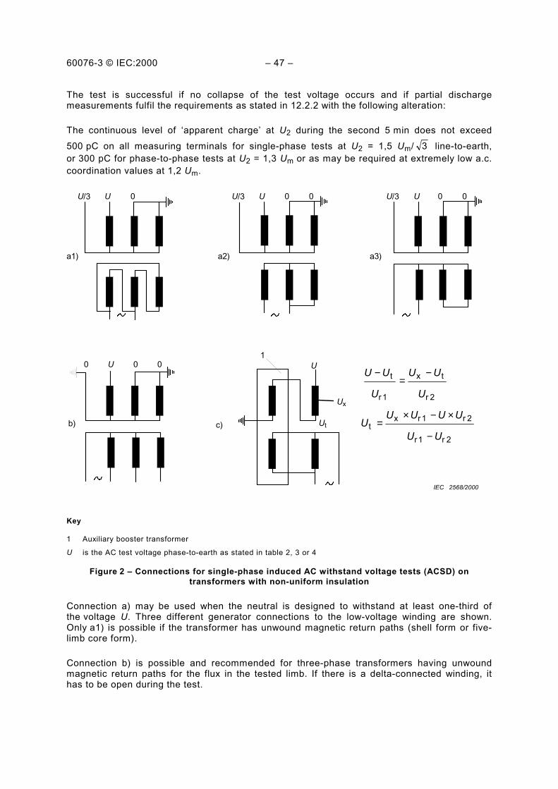
The test sequence for a three-phase transformer consists of three single-phase applications oftest voltage with different points of the winding connected to earth at each time. Recommendedtest connections which avoid excessive overvoltage between line terminals are shown infigure 2. There are also other possible methods.
Other separate windings shall generally be earthed at the neutral if they are star-connected,and at one of the terminals if they are delta-connected.
The voltage per turn during the test reaches different values depending on the test connection.The choice of a suitable test connection is determined by the characteristics of the transformerwith respect to operating conditions or test plant limitations. The test time and the timesequence for the application of test voltage shall be as described in 12.1 and 12.2.2.
For the partial discharge performance evaluation, during the phase-to-phase test, measure-ments should be taken at U2 = 1,3 Um.
NOTE The value U2 = 1,3 Um is valid up to Um = 550 kV with AC test values greater than 510 kV. For Um = 420 kVand 550 kV with AC test values of 460 kV or 510 kV, the partial discharge evaluation level should be reducedto U2 = 1,2 Um in order not to exceed the AC withstand voltages of table 4.
For the three single-phase tests for the phase-to-earth insulation, U1 is the test voltageaccording to tables 2, 3 or 4 and U2 = 1,5 Um/ 3 . Examples are given in table D.2.
NOTE 1 In the case of transformers with complicated winding arrangements, it is recommended that the completeconnection of all windings during the test be reviewed between supplier and purchaser at the contract stage, inorder that the test represents a realistic service stress combination as far as possible.
NOTE 2 An additional induced AC withstand test with symmetrical three-phase voltages produces higher stressesbetween phases. If this test is specified, the clearances between phases should be adjusted accordingly andspecified at the contract stage.
NOTE 3 In France, partial discharge measurements during short-duration a.c. test on non-uniform insulated high-voltage windings are not acceptable.
60076-3 © IEC:2000 47
The test is successful if no collapse of the test voltage occurs and if partial dischargemeasurements fulfil the requirements as stated in 12.2.2 with the following alteration:
The continuous level of apparent charge at U2 during the second 5 min does not exceed500 pC on all measuring terminals for single-phase tests at U2 = 1,5 Um/ 3 line-to-earth,or 300 pC for phase-to-phase tests at U2 = 1,3 Um or as may be required at extremely low a.c.coordination values at 1,2 Um.
b)
0 U 0 0
c)
1U
Ux
Ut
a1) a2) a3)
U/3 U 0 U/3 U 0 0 U/3 U 0 0
2r1r
2r1rxt
2r
tx
1r
t
UU
UUUUU
U
UU
U
UU
−
×−×=
−=
−
IEC 2568/2000
Key
1 Auxiliary booster transformer
U is the AC test voltage phase-to-earth as stated in table 2, 3 or 4
Figure 2 Connections for single-phase induced AC withstand voltage tests (ACSD) ontransformers with non-uniform insulation
Connection a) may be used when the neutral is designed to withstand at least one-third ofthe voltage U. Three different generator connections to the low-voltage winding are shown.Only a1) is possible if the transformer has unwound magnetic return paths (shell form or five-limb core form).
Connection b) is possible and recommended for three-phase transformers having unwoundmagnetic return paths for the flux in the tested limb. If there is a delta-connected winding, ithas to be open during the test.

60076-3 © IEC:2000 – 49 –
Connection c) shows an auxiliary booster transformer, which gives a bias voltage Ut at theneutral terminal of an auto-transformer under test. Rated voltages of the two auto-connectedwindings are Ur1, Ur2, and the corresponding test voltages U, Ux. This connection may also beused for a three-phase transformer without unwound magnetic return paths having the neutralinsulation designed for less than one-third of the voltage U.
12.4 Long-duration induced AC voltage test (ACLD) with non-uniformly and/or uniformlyinsulated high-voltage windings, according to table 1
A three-phase transformer shall be tested either phase-by-phase in a single-phase connectionthat gives voltages on the line terminals according to figure 3, or in a symmetrical three-phaseconnection. The latter case requires special precautions, see note 1 below.
A three-phase transformer supplied from the low-voltage winding side with a delta-connectedhigh-voltage winding can receive the proper test voltages as described below only in a three-phase test with a floating high-voltage winding. As the voltages with respect to earth in such atest depend fully on the phase capacitances to earth and other windings, this test is notrecommended for Um ≥ 245 kV in table 1. Any flashover from one of the line terminals to earthcan result in major damage of the other two phases due to sudden high voltages. For thesekind of transformers, a single-phase connection according to figure 3 is preferred, successivelyapplied to all three phases of a three-phase transformer.
Phase-by-phase testing of delta-connected windings implies double testing of each lineterminal and its connected winding. As the test is a quality control test and not a design provingtest, the test can be repeated for the line terminal involved without damaging the insulation.
The neutral terminal, if present, of the winding under test shall be earthed. For other separatewindings, if they are star-connected they shall be earthed at the neutral, and if they are delta-connected they shall be earthed at one of the terminals or earthed through the neutral of thesupplying voltage source. Tapped windings shall be connected to the principal tapping, unlessotherwise agreed.
The test arrangement (three-phase or single-phase) shall be agreed between the supplier andpurchaser when placing the order.
NOTE 1 If a three-phase star-connected transformer is to be tested in three-phase connection, the test voltagebetween phases is higher than in the single-phase connection. This may influence the phase-to-phase insulationdesign and will require larger external clearances.
NOTE 2 If a three-phase delta-connected transformer is to be tested in single-phase connection, the test voltagebetween phases is higher than in the three-phase connection. This may influence the phase-to-phase insulationdesign.

60076-3 © IEC:2000 – 51 –
U -0,5U -0,5U U
-U
2U
IEC 274/2000
IEC 275/2000
Y- connected D-connected
Figure 3 – Phase-by-phase test on Y- or D-connected three-phase transformers
The voltage shall be
– switched on at a level not higher than one-third of U2;
– raised to 1,1 Um / 3 and held there for a duration of 5 min;
– raised to U2 and held there for a duration of 5 min;
– raised to U1, held there for the test time as stated in 12.1;
– immediately after the test time, reduced without interruption to U2 and held there for aduration of at least 60 min when Um ≥ 300 kV or 30 min for Um < 300 kV to measure partialdischarges;
– reduced to 1,1 Um / 3 and held there for a duration of 5 min;
– reduced to a value below one-third of U2 before switching off.
The duration of the test, except for the enhancement level U1, shall be independent of the testfrequency.
Ustart
A
B
C
D
E
1,1 Um / √3
U2
U1
U2
1,1 Um / √3
<Ustart
IEC 276/2000
A = 5 minB = 5 minC = test time
D = 60 min for Um ≥ 300 kV or 30 min for Um < 300 kV
E = 5 min
Figure 4 – Time sequence for the application of test voltage forinduced AC long-duration tests (ACLD)

60076-3 © IEC:2000 – 53 –
During the whole application of the test voltage, partial discharges shall be monitored.
The voltages to earth shall be:
U1 = 1,7 Um / 3
U2 = 1,5 Um / 3
NOTE For network conditions where transformers are severely exposed to overvoltages, values for U1 and U2 can
be 1,8 Um / 3 and 1,6 Um / 3 respectively. This requirement shall be clearly stated in the enquiry.
The background noise level shall not exceed 100 pC.
NOTE It is recommended that the background noise level should be considerably lower than 100 pC in order toinsure that any inception and extinction of partial discharges can be detected and recorded. The above-mentioned
value of 100 pC at 1,1 Um / 3 is a compromise for the acceptance of the test.
The partial discharges shall be observed and evaluated as follows. Further information may beobtained from annex A, which, in turn, refers to IEC 60270.
– Measurements shall be carried out at the line terminals of all non-uniformly insulatedwindings, which means that the higher and lower voltage line terminals of an auto-connected pair of windings will be measured simultaneously.
– The measuring channel from each terminal used shall be calibrated with repetitive impulsesbetween the terminal and earth, and this calibration is used for the evaluation of readingsduring the test. The apparent charge measured at a specific terminal of the transformer,using the appropriate calibration, shall refer to the highest steady-state repetitive impulses.Occasional bursts of high partial discharge level should be disregarded. Continuous dis-charges for any length of time occurring at irregular intervals can be accepted upto 500 pC, provided there is no steadily increasing tendency.
– Before and after the application of test voltage, the background noise level shall berecorded on all measuring channels.
– During the raising of voltage up to level U2 and reduction from U2 down again, possibleinception and extinction voltages should be noted. Measurement of the apparent charge
shall be taken at 1,1 Um / 3 .
– A reading shall be taken and noted during the first period at voltage U2. No apparent chargevalues are specified for this period.
– No values of apparent charge are assigned to the application of U1.
– During the whole of the second period at voltage U2, the partial discharge level shall becontinuously observed and readings shall be recorded every 5 min.
The test is successful if
– no collapse of the test voltage occurs;
– the continuous level of partial discharges does not exceed 500 pC during the long durationtest at U2;
– the partial discharge behaviour shows no continuously rising tendency at U2. Occasionalhigh bursts of non-sustained nature should be disregarded;
NOTE North American practice limits the allowable change during the test to 150 pC to recognize possibleinternal problems.
– the continuous level of apparent charges does not exceed 100 pC at 1,1 Um / 3 .

60076-3 © IEC:2000 – 55 –
As long as no breakdown occurs, and unless very high partial discharges are sustained for along time, the test is regarded as non-destructive. A failure to meet the partial dischargeacceptance criteria shall therefore not warrant immediate rejection, but lead to consultationbetween purchaser and supplier about further investigations. Suggestions for such proceduresare given in annex A.
Concerning difficulties with bushings during the test, see also clause 4.
13 Lightning impulse (LI) test
13.1 General
When required, lightning impulse (LI) tests shall only be made on windings that have terminalsbrought out through the transformer tank or cover.
General definitions of terms related to impulse tests, requirements for test circuits,performance tests and routine checks on approved measuring devices may be found inIEC 60060-1. Further information is given in IEC 60722.
For oil-immersed transformers, the test voltage is normally of negative polarity, because thisreduces the risk of erratic external flashovers in the test circuit.
Bushing spark gaps may be removed or their spacing increased to prevent sparkover duringthe test.
When non-linear elements or surge diverters – built into the transformer or external – areinstalled for the limitation of transferred overvoltage transients, the impulse test procedureshall be discussed in advance for each particular case. If such elements are present during thetest, the evaluation of test records (see 13.5) may be different compared to the normal impulsetest. By their very nature, non-linear protective devices connected across the windings maycause differences between the reduced full wave and the full-wave impulse oscillograms. Toprove that these differences are indeed caused by operation of these devices this, should bedemonstrated by making two or more reduced full-wave impulse tests at different voltage levelsto show the trend in their operation. To show the reversibility of any non-linear effects, thesame reduced full-wave impulses shall follow up the full-wave test voltage in a reversed way.
EXAMPLE 60 %, 80 %, 100 %, 80 %, 60 %.
The test impulse shall be a full standard lightning impulse: 1,2 µs ± 30 %/50 µs ± 20 %.
There are cases, however, where this standard impulse shape cannot reasonably be obtained,because of low winding inductance or high capacitance to earth. The resulting impulse shape isthen often oscillatory. Wider tolerances may, in such cases, be accepted by agreementbetween purchaser and supplier. See IEC 60722.

60076-3 © IEC:2000 – 57 –
The impulse shape problem may also be treated by alternative methods of earthing during thetest, see 13.3.
The impulse circuit and measuring connections shall remain unchanged during calibration andfull voltage tests.
NOTE The information given in IEC 60722 with reference to waveshape evaluation is based on oscilloscopicrecords, engineering rules and eye evaluation of waveshape parameters. With the application of digital recordersaccording to IEC 61083-1 and IEC 61083-2 in high-voltage impulse testing of power transformers, a clear warningwith respect to amplitude and time parameters should be given with respect to the evaluation of non-standardwaveshapes.
In particular, when testing high power rated low-voltage windings with resulting unipolar overshoots with frequenciesless than 0,5 MHz, IEC 61083-2 is not applicable for the amplitude evaluation of such non-standard waveshapes.Errors in excess of 10 % have been observed due to the built-in curve smoothing algorithms in the digitizers.
In such cases, careful evaluation of the raw data plots using engineering judgement is needed. A parallelmeasurement of the peak voltage by a peak voltmeter according to IEC 60790 is highly recommended.
13.2 Test sequence
The test sequence shall consist of one impulse of a voltage between 50 % and 75 % of the fulltest voltage, and three subsequent impulses at full voltage. If, during any of these applications,an external flashover in the circuit or across a bushing spark gap should occur, or if theoscillographic recording should fail on any of the specified measuring channels, that applicationshall be disregarded and a further application made.
NOTE Additional impulses at amplitudes not higher than 50 % may be used but need not be shown in the testreport.
13.3 Test connections
13.3.1 Test connections during tests on line terminals
The impulse test sequence is applied to each of the line terminals of the tested winding insuccession. In the case of a three-phase transformer, the other line terminals of the windingshall be earthed directly or through a low impedance, not exceeding the surge impedance ofthe connected line.
If the winding has a neutral terminal, the neutral shall be earthed directly or through a lowimpedance such as a current measuring shunt. The tank shall be earthed.
In the case of a separate winding transformer, terminals of windings not under test are likewiseearthed directly or through impedances, so that in all circumstances, the voltage appearing atthe terminals is limited to not more than 75 % of their rated lightning impulse withstand voltagefor star-connected windings, and 50 % for delta-connected windings.
In the case of an auto-transformer, when testing the line terminals of the high-voltage winding,it may happen that the standard impulse wave-form cannot reasonably be obtained if the lineterminals of the common winding are earthed directly or through a current measuring shunt.The same applies to the testing of the line terminals of the common winding if the lineterminals of the high-voltage winding are earthed. It is then permissible to earth the non-testedline terminals through resistors not exceeding 400 Ω. Furthermore, the voltages appearing onthe non-tested line terminals to earth should not exceed 75 % of their rated lightning impulsewithstand voltage for star-connected windings and 50 % for delta-connected windings.

60076-3 © IEC:2000 – 59 –
When impulse testing windings with low impedances, it may be difficult to obtain correctimpulse shape on the tested terminals. In this case wider tolerances have to be accepted, see13.1. It is also possible to simplify the problem by earthing the non-tested terminals of thetested phase through resistors. The resistance value shall be chosen so that the voltageappearing on the terminals is limited to not more than 75 % of their rated lightning impulsewithstand voltage for star-connected windings or 50 % for delta connected windings.Alternatively, by agreement at the time of placing the order the transferred surge method maybe employed, see 13.3.3.
Exceptions from this main procedure are given in 13.3.2 and 13.3.3.
13.3.2 Impulse test on a neutral terminal
When the neutral terminal of a winding has a rated impulse withstand voltage, it may beverified by a test as follows:
a) by indirect application:
Test impulses are applied to any one of the line terminals or to all three line terminals of athree-phase winding connected together. The neutral terminal is connected to earth throughan impedance or is left open, and the voltage amplitude developed across this impedanceor to earth, when a standard lightning impulse is applied to the line terminal, shall be equalto the rated withstand voltage of the neutral terminal. No prescriptions are given for theshape of the resulting impulse across the impedance. The amplitude of the impulse appliedto the line terminal is not prescribed, but shall not exceed 75 % of the rated lightningimpulse withstand voltage of the line terminal.
b) by direct application:
Test impulses corresponding to the rated withstand voltage of the neutral are applieddirectly to the neutral with all line terminals earthed. In this case, however, a longer durationof the front time is allowed, up to 13 µs.
13.3.3 The transferred surge method on low-voltage windings
When the low-voltage winding cannot be subjected to lightning overvoltages from the low-voltage system, this winding may, by agreement between supplier and purchaser, be impulsetested with surges transferred from the high-voltage winding.
This method is also to be preferred when the design is such that an impulse directly applied tothe low-voltage winding could result in unrealistic stressing of higher voltage windings,particularly when there is a large tapping winding physically adjacent to the low-voltagewinding.
With the transferred surge method, the tests on the low-voltage winding are carried out byapplying the impulses to the adjacent higher voltage winding. The line terminals of the low-voltage winding are connected to earth through resistances of such value that the amplitude oftransferred impulse voltage between line terminals and earth, or between different lineterminals or across a phase winding, will be as high as possible but not exceeding the ratedimpulse withstand voltage. The magnitude of the applied impulses shall not exceed the impulselevel of the winding to which the impulses are applied.
The details of the procedure shall be agreed before the test.

60076-3 © IEC:2000 – 61 –
13.4 Records of test
The oscillographic or digital records obtained during calibrations and tests shall clearly showthe applied voltage impulse shape (front time, time-to-half value and amplitude).
At least one more measurement channel shall be used. In most cases an oscillogram of thecurrent flowing to earth from the tested winding (neutral current) or the capacitive probecurrent, i.e. the current transferred to the non-tested and shorted winding, will represent thebest sensitivity for fault indication. The current flowing from tank to earth, or the transferredvoltage in a non-tested winding, are examples of alternative suitable measuring quantities. Thedetection method chosen shall be agreed between supplier and purchaser.
Further recommendations about failure detection, suitable time-base durations, etc. are givenin IEC 60722.
13.5 Test criteria
The absence of significant differences between voltage and current transients recorded atreduced voltage and those recorded at full test voltage constitutes evidence that the insulationhas withstood the test.
The detailed interpretation of the oscillographic or digital test records and discrimination ofmarginal disturbances from true records of failure require a great deal of skill and experience.Further information is given in IEC 60722.
If there is doubt about the interpretation of possible discrepancies between oscillograms ordigital records, three subsequent impulses at full voltage shall be applied, or the whole impulsetest on the terminal shall be repeated. The test shall be considered successfully passed if nofurther and progressive deviations are observed.
Additional observations during the test (abnormal sound effects, etc.) may be used to confirmthe interpretation of the oscillographic or digital records, but they do not constitute evidence inthemselves.
Any difference in the wave shape between the reduced full wave and final full wave detected bycomparison of the two current oscillograms may be indication of failure or deviations due tonon-injurious causes. They should be fully investigated and explained by a new reduced waveand full-wave test. Examples of possible causes of different wave shapes are operation ofprotective devices, core saturation, or conditions in the test circuit external to the transformer.
14 Test with lightning impulse chopped on the tail (LIC)
14.1 General
The test is a special test and should be used for special applications on line terminals of awinding. When it has been agreed to make this test, it shall be combined with the full lightningimpulse test in the manner described below. The peak value of the chopped impulse shall be1,1 times the amplitude of full impulse.

60076-3 © IEC:2000 – 63 –
Usually, the same settings of the impulse generator and measuring equipment are used, andonly the chopping gap equipment is added. The standard chopped lightning impulse shall havea time to chopping between 2 µs and 6 µs.
Different time bases may be used to record lightning impulses chopped on the tail.
14.2 Chopping gap and characteristics of the chopping
It is recommended to use a triggered-type chopping gap with adjustable timing, although aplain rod-rod gap is allowed. The chopping circuit shall be so arranged that the amount ofoverswing to opposite polarity of the recorded impulse will be limited to not more than 30 % ofthe amplitude of the chopped impulse; the insertion of an impedance Z in the chopped circuit isusually necessary to maintain this limit.
14.3 Test sequence and test criteria
As indicated above, the test is combined with the full impulse test in a single sequence. Therecommended order of the different impulse applications is:
– one reduced level full impulse;
– one full level full impulse;
– one or more reduced level chopped impulse(s);
– two full level chopped impulses;
– two full level full impulses.
The same types of measuring channels and oscillographic or digital records are specified asfor the full-wave impulse test.
In principle, the detection of faults during a chopped impulse test depends essentially on acomparison of the oscillographic or digital records of the full level and reduced level choppedimpulses. The neutral current record (or any other supplementary recording) presents asuperposition of transient phenomena due to the front of the original impulse and from thechopping. Account should therefore be taken of the possible variations, even slight, of thechopping time delay. The later part of the oscillation pattern is then modified, and this effect isdifficult to separate from the record of a fault. Frequency changes after the chopping, however,need to be clarified.
The recordings of successive full impulse tests at full level constitute a supplementary criterionof a fault, but they do not constitute in themselves a quality criterion for the chopped impulsetest.
15 Switching impulse test (SI)
15.1 General
General definitions of terms related to impulse tests, requirements on test circuits, perform-ance tests and routine checks on approved measuring devices, may be found in IEC 60060-1.Further information is given in IEC 60722.

60076-3 © IEC:2000 – 65 –
The impulses are applied either directly from the impulse voltage source to a line terminal ofthe winding under test, or to a lower voltage winding so that the test voltage is inductivelytransferred to the winding under test. The specified test voltage shall appear between line andearth. Neutral terminals shall be earthed. In a three-phase transformer, the voltage developedbetween line terminals during the test shall be approximately 1,5 times the voltage between lineand neutral terminals, see 15.3.
The test voltage is normally of negative polarity to reduce the risk of erratic external flashoverin the test circuit.
The voltages developed across different windings of the transformer are approximatelyproportional to the ratio of numbers of turns and the test voltage will be determined by thewinding with the highest Um value, see clause 6.
The voltage impulse shall have a virtual front time of at least 100 µs, a time above 90 % of thespecified amplitude of at least 200 µs, and a total duration from the virtual origin to the firstzero passage at least 500 µs but preferably 1 000 µs.
NOTE The impulse wave shape is purposely different from the standard waveshape of 250/2 500 µs recommendedin IEC 60060-1, since IEC 60060-1 is valid for non-saturable magnetic circuit equipment.
The front time shall be selected by the supplier so that the voltage distribution along thewinding under test will be essentially linear. Its value is usually greater than 100 µs but lessthan 250 µs. During the test considerable flux is developed in the magnetic circuit. The impulsevoltage can be sustained up to the instant when the core reaches saturation and themagnetizing impedance of the transformer becomes drastically reduced.
The maximum possible impulse duration can be increased by introducing remanence ofopposite polarity before each full-voltage test impulse. This is accomplished by lower voltageimpulses of similar shape but opposite polarity. See IEC 60722.
Advice for the selection of tap position is given in clause 8.
15.2 Test sequence and records
The test sequence shall consist of one impulse (calibration impulse) of a voltage between 50 %and 75 % of the full test voltage and three subsequent impulses at full voltage. If theoscillographic or digital recording should fail, that application shall be disregarded and a furtherapplication made. Oscillographic or digital records shall be obtained of at least the impulsewave-shape on the line terminal under test and preferably the neutral current.
NOTE Due to the influence of magnetic saturation on impulse duration, successive oscillograms are different andreduced and full level test recordings are not identical. To limit this influence, after each test impulse at identicaltest levels, demagnetizing impulses at reduced level of opposite polarity are required.
15.3 Test connections
During the test the transformer shall be in a no-load condition. Windings not used for the testshall be solidly earthed at one point but not short-circuited. For a single-phase transformer, theneutral terminal of the tested winding shall be solidly earthed.

60076-3 © IEC:2000 – 67 –
A three-phase winding shall be tested phase by phase with the neutral terminal earthed andwith the transformer so connected that a voltage of opposite polarity and about half amplitudeappears on the two remaining line terminals which may be connected together.
To limit the voltage of opposite polarity to approximately 50 % of the applied level, it isrecommended to connect high ohmic damping resistors (10 kΩ to 20 kΩ) to earth at the non-tested phase terminals.
Bushing spark gaps and additional means for limitation of overvoltages are treated as specifiedfor the lightning impulse test, see 13.1.
15.4 Test criteria
The test is successful if there is no sudden collapse of voltage or discontinuity of the neutralcurrent indicated on the oscillographic or digital records.
Additional observations during the test (abnormal sound effects, etc.) may be used to confirmthe oscillographic records, but they do not constitute evidence in themselves.
16 External clearances in air
16.1 General
Clearances in air are understood as distances where the electrostatic field is free ofdisturbance by insulator bodies. This standard does not deal with the requirements of effectiveflashover distance or creepage distance along the bushing insulators nor does it consider therisk from intrusion of birds and other animals.
When establishing the requirements of the present standard in the higher voltage ranges, it hasbeen recognized that the bushing ends have normally rounded electrode shapes.
The clearance requirements are valid between such rounded electrodes. It is assumed thatconductor clamps with their associated shield electrodes are suitably shaped so that they donot reduce the flashover voltage. It is also assumed that the arrangement of incomingconductors does not reduce the effective clearances provided by the transformer itself.
NOTE If the purchaser intends to make his connection in a particular way which is likely to reduce the effectiveclearances, this should be mentioned in the enquiry.
In general, the provision of adequate clearances in air becomes technically difficult mainly athigh system voltages, particularly for relatively small units, or when the installation space isrestricted. The principle followed in this standard is to provide minimum, non-critical clearanceswhich are satisfactory without further discussion or proof under various system conditions andin different climates. Other clearances based on past or current practice shall be subject toagreement between purchaser and supplier.

60076-3 © IEC:2000 – 69 –
The recommended clearances are referred to the rated withstand voltages of the internalinsulation of the transformer, unless otherwise specified in the enquiry and order. When theclearances of the transformer are equal to or larger than the values specified in this standardand the bushings have properly selected ratings according to IEC 60137, then the externalinsulation of the transformer shall be regarded as satisfactory without further testing.
NOTE 1 The impulse withstand strength of the external insulation is polarity dependant, in contrast to what isassumed for the internal insulation. The tests prescribed for the internal insulation of the transformer do notautomatically verify that the external insulation is satisfactory. The recommended clearances are dimensioned forthe more onerous polarity (positive).
NOTE 2 It is recognized that in some countries, clearances may be different if based on LI and AC withstandvoltages only.
NOTE 3 If a clearance smaller than that according to the paragraph above has been used for a contract, a typetest may be required on an arrangement simulating the actual clearance, or on the transformer itself.Recommended test procedures for such cases are given.
If the transformer is specified for operation at an altitude higher than 1 000 m, the clearancerequirements shall be increased by 1 % for every 100 m by which the altitude exceeds 1 000 m.
Requirements are given for the following clearances:
– clearance phase-to-earth and phase-to-neutral;
– clearance phase-to-phase between phases of the same winding;
– clearance between a line terminal of the high voltage winding and a line terminal of a lowervoltage winding.
It follows from the above that the recommended values are in effect minimum values. Thedesign clearances shall be stated on the outline drawing. These are nominal values subject tonormal manufacturing tolerances and they have to be selected so that the actual clearanceswill be at least equal to the specified values.
These statements shall be taken as proof that the transformer complies with the recom-mendations of this standard, or with the modified values which may have been agreed for theparticular contract.
16.2 Bushing clearance requirements as determined by transformer insulationwithstand voltages
The requirements are formulated as described below, depending on the Um voltage value ofthe winding.
16.2.1 Um ≤ 170 kV
The same distance shall apply for clearances phase-to-earth, phase-to-neutral, phase-to-phase, and towards terminals of a lower voltage winding.
The recommended minimum clearances are given in tables 5 and 6 with reference to the ratedwithstand voltages which appear in tables 2 and 3.

60076-3 © IEC:2000 – 71 –
If a type test on a reduced clearance is to be conducted this shall be a lightning impulse test,dry, with positive impulse, three shots, with the test voltage according to tables 5 or 6respectively.
NOTE As indicated in table 2, some low lightning impulse withstand values can be specified according toIEC 60071-1. A check whether this condition requires a larger phase-to-phase clearance should be made.
16.2.2 Um > 170 kV
For equipment with Um > 170 kV where switching impulse testing is specified, therecommended clearances are given in table 7.
It is assumed that the requirements for external insulation are the same irrespective of theperformance of the short-duration AC withstand voltage test according to the values given intable 4.
The internal insulation is verified by a switching impulse test with negative test voltage on thetested phase, and with approximately 1,5 times the test voltage between the phases on three-phase transformers, see IEC 60071-1.
For the external insulation the phase-to-phase withstand voltage is defined differently. Anappropriate test procedure involves positive polarity impulses for a configuration phase-to-earth, and opposite polarity impulses for phase-to-phase clearances, see 16.2.2.3. This hasbeen considered for the clearance values given in table 7.
16.2.2.1 Clearance phase-to-earth, phase-to-neutral, and phase-to-phase betweenphases of the same winding
The clearance from the high-voltage bushing top to earth (tank, conservator, coolingequipment, switchyard structures, etc.) or to the neutral terminal is determined from column 4of table 7.
The clearance between bushing caps of different phases is determined from column 5 oftable 7.
16.2.2.2 Clearance between terminals of different windings
The clearance between terminals of different windings of the transformer shall be checked withregard to both switching impulse and lightning impulse conditions.
The switching impulse withstand requirement is based on the calculated voltage differencewhich appears between the two terminals, see clause 15. This voltage difference determinesthe required clearance with regard to the switching impulse condition. Figure 6 is used to findthe recommended clearance if the terminals receive opposite polarity voltages and the ratiobetween the appearing voltages is 2 or less. In other cases, figure 5 applies.
NOTE If figures 5 and 6 are compared, it appears that a phase-to-phase clearance withstands a higher voltagedifference than the same distance would do in a phase-to-earth configuration. The reason is that in the phase-to-phase configuration the two terminals are supposed to have opposite polarity, and the maximum dielectric gradientat either of them (which is largely determined by the voltage to earth) is relatively lower. It is assumed also that theelectrodes have a rounded shape.

60076-3 © IEC:2000 – 73 –
The clearance shall, however, also fulfil the lightning impulse withstand requirement, whichpre-supposes that the lower voltage winding terminal is at earth potential when rated lightningimpulse withstand voltage is applied to the high-voltage terminal. The distance requirement incolumn 6 of table 7 and figure 7, corresponding to this rated lightning impulse voltage, hastherefore to be fulfilled between the two terminals. The higher of the two clearancerequirements shall apply.
The switching impulse test on three-phase transformers will induce voltages between phases ofother star-connected windings as well. It shall be checked whether this condition requires alarger phase-to-phase clearance in such a winding than as prescribed for this winding alonesuch as in 16.2.1.
16.2.2.3 Type test procedure
If a type test on a reduced clearance is to be conducted, the test procedure shall be as follows.
A test on a configuration phase-to-earth (or phase-to-neutral, or towards a terminal of a lowervoltage winding) shall consist of a switching impulse test, dry, with positive polarity on the lineterminal of the winding (the higher voltage winding). The counter electrode shall be earthed. Ifthe tested terminal belongs to a three-phase winding, the other line terminals shall also beearthed.
NOTE This test is not generally feasible on complete three-phase transformers and may therefore have to beconducted on a model simulating the actual configuration of the transformer.
Tests on the phase-to-phase clearances of a three-phase transformer shall consist of switchingimpulse tests, dry, with half of the specified test voltage, positive, on one line terminal, theother half, negative, on another line terminal, and the third line terminal earthed.
The combinations of phase-to-earth and phase-to-phase test voltages are reproduced intable 7.
When the outer phases are placed symmetrically with respect to the middle phase, it issufficient to make two separate tests, one with positive polarity on the middle phase, an outerphase having negative polarity and the other with positive polarity on an outer phase, themiddle phase having negative polarity. If the line terminal arrangement is asymmetrical, it maybe necessary to perform more than two tests.
Each test shall consist of 15 applications of impulse voltage with a wave shape 250/2 500 µs inaccordance with IEC 60060-2.
NOTE The above test procedure for phase-to-phase external clearances, differs in several respects from theswitching impulse test procedure specified for the internal insulation of the transformer in clause 14. The two testprocedures do not replace each other.

60076-3 © IEC:2000 75
Table 5 Recommended minimum clearances phase-to earth, phase-to-phase,phase-to-neutral and to lower voltage windings from bushing live parts
on power transformers having windings with highest voltagefor equipment Um ≤≤≤≤ 170 kV
Series I based on European practice
Highest voltage forequipment Um
kV r.m.s
Rated lightningimpulse withstand
voltage
kV peak
Minimum clearance
mm
3,6
7,2
12
17,5
24
36
52
72,5
100
123
145
170
20
40
60
75
95
125
145
170
250
325
450
550
650
750
-
60
90
110
170
210
275
280
450
630
830
900
1250
1450

60076-3 © IEC:2000 – 77 –
Table 6 – Recommended minimum clearances phase-to-earth, phase-to-phase,phase-to-neutral and to lower voltage windings from bushing live parts
on power transformers having windings with highest voltagefor equipment Um ≤ 169 kV –
Series II based on North American practice
Highest voltagefor
equipment Um
kV r.m.s.
Rated lightningimpulse withstand
voltage
kV peak
Minimumclearance
mm
60 (see note) 65 (see note)
<15 75 100
95 (see note) 140 (see note)
110 165
26,4 150 225
36,5 200 330
48,3 250 450
72,5 350 630
121 450 830
145 550 1 050
169 650 1 250
750 1 450
NOTE Indicates value for distribution transformers only.
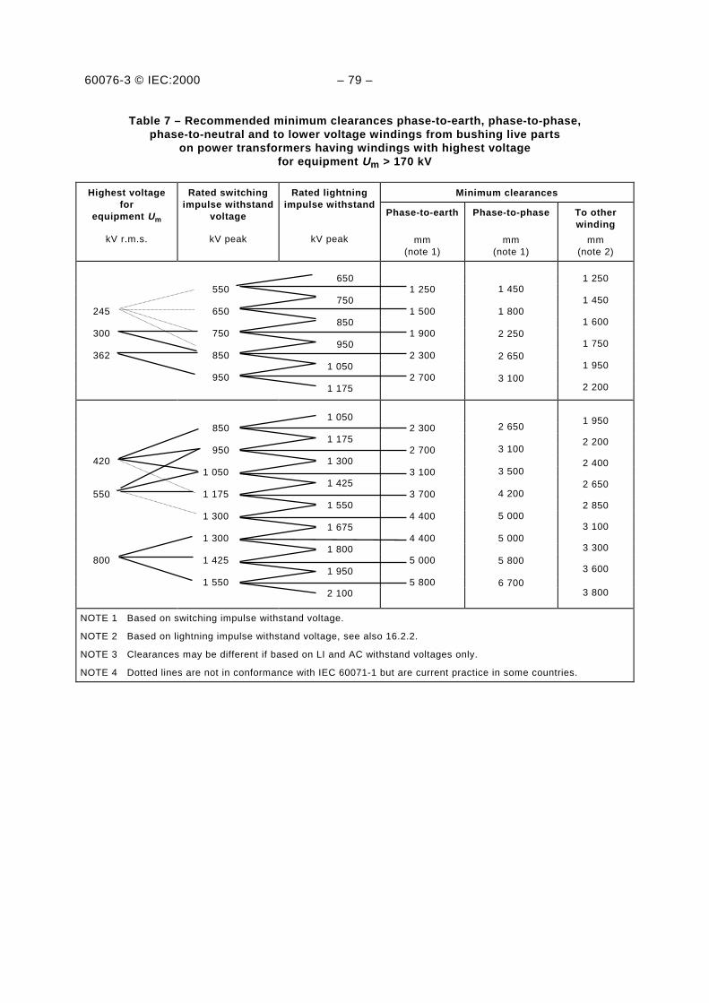
60076-3 © IEC:2000 – 79 –
Table 7 – Recommended minimum clearances phase-to-earth, phase-to-phase,phase-to-neutral and to lower voltage windings from bushing live parts
on power transformers having windings with highest voltagefor equipment Um > 170 kV
Minimum clearancesHighest voltagefor
equipment Um
kV r.m.s.
Rated switchingimpulse withstand
voltage
kV peak
Rated lightningimpulse withstand
kV peak
Phase-to-earth
mm(note 1)
Phase-to-phase
mm(note 1)
To otherwinding
mm(note 2)
650 550 1 250
750245 650 1 500
850300 750 1 900
950362 850 2 300
1 050 950 2 700
1 175
1 450
1 800
2 250
2 650
3 100
1 250
1 450
1 600
1 750
1 950
2 200
1 050 850 2 300
1 175 950 2 700
420 1 3001 050 3 100
1 425550 1 175 3 700
1 5501 300 4 400
1 6751 300 4 400
1 800800 1 425 5 000
1 9501 550 5 800
2 100
2 650
3 100
3 500
4 200
5 000
5 000
5 800
6 700
1 950
2 200
2 400
2 650
2 850
3 100
3 300
3 600
3 800
NOTE 1 Based on switching impulse withstand voltage.
NOTE 2 Based on lightning impulse withstand voltage, see also 16.2.2.
NOTE 3 Clearances may be different if based on LI and AC withstand voltages only.
NOTE 4 Dotted lines are not in conformance with IEC 60071-1 but are current practice in some countries.

60076-3 © IEC:2000 – 81 –
Figure 5 – Clearance phase-to-earth based on rated switching impulse withstand voltage
Figure 6 – Clearance phase-to-phase based on switching impulse voltageappearing between phases
IEC 2569/2000
IEC 2570/2000

60076-3 © IEC:2000 – 83 –
Figure 7 – Clearance based on lightning impulse voltage
IEC 2571/2000

60076-3 © IEC:2000 – 85 –
Annex A(informative)
Application guide for partial discharge measurementsduring induced a.c. withstand voltage test on transformers
according to 12.2, 12.3 and 12.4
A.1 Introduction
A partial discharge (p.d.) is an electric discharge that only partially bridges the insulationbetween conductors. In a transformer, such a partial discharge causes a transient change ofthe voltage to earth at every externally available winding terminal.
Measuring impedances are connected effectively between the earthed tank and the terminals,usually through a bushing tap or through a separate coupling capacitor, as detailed inclause A.2.
The actual charge transferred at the site of a partial discharge cannot be measured directly.The preferred measuring partial discharge activities on power transformers is the determinationof the apparent charge q as defined in IEC 60270.
The apparent charge q related to any measuring terminal is determined by a suitablecalibration, see clause A.2.
A particular partial discharge gives rise to different values of apparent charge at differentterminals of the transformer. The comparison of simultaneously collected indications atdifferent terminals may give information about the location of the partial discharge sourcewithin the transformer, see clause A.5.
The acceptance test procedures specified in 12.2, 12.3 and 12.4 call for measurement ofapparent charge at the winding line terminals.
A.2 Connection of measuring and calibration circuits – Calibration procedure
The measuring equipment is connected to the terminals by matched coaxial cables. Themeasuring impedance is, in its simplest form, the matching impedance of the cable, which mayin turn be the input impedance of the measuring instrument.
In order to improve the signal-to-noise ratio of the complete measuring system, it may beconvenient to make use of tuned circuits, pulse transformers, and amplifiers between the testobject terminals and the cable.
The circuit should represent a reasonably constant resistance, when viewed from the testobject terminals, throughout the frequency range used for the partial discharge measurements.

60076-3 © IEC:2000 – 87 –
During the measurement of partial discharge between a line terminal of a winding and theearthed tank, the preferred arrangement is to install the measuring impedance Zm effectivelybetween the value of the capacitance graded bushing tap and the earthed flange, seefigure A.1. If a capacitance tap is not provided, it is also possible to insulate the bushing flangefrom the tank and use it as the measuring terminal. The equivalent capacitances between thecentral conductor, the measuring terminal and earth, act as an attenuator for the partialdischarge signal. This is, however, covered by the calibration which takes place between thetop terminal of the bushing and earth.
C0
Zm
C1
C2
IEC 280/2000
Figure A.1 – Calibration circuit for partial discharge measurement when thevalue of the capacitance graded bushing is available
If measurements have to be taken at a live terminal without any available value of thecapacitance graded bushing tap (or insulated flange), the method with a high-voltage couplingcapacitor is used. A partial discharge free capacitor is required and its capacitance value Cshould be suitably large in comparison with the calibration generator capacitance C0. Themeasuring impedance (with a protective gap) is connected between the low-tension terminal ofthe capacitor and earth, see figure A.2.
The calibration of the complete measuring system is made by injection of known chargesbetween the calibration terminals. According to IEC 60270, a calibration generator consists of astep voltage pulse generator with short rise time and a small series capacitor of knowncapacitance C0. The rise time should be not more than 0,1 µs and C0 should be in the rangeof 50 pF to 100 pF. When this generator is connected between two calibration terminalspresenting a capacitance much greater than C0, the injected charge from the pulse generatorwill be:
q0 = U0 × C0
where U0 is the voltage step (usually between 2 V and 50 V).
It is convenient if the calibration generator has a repetition frequency of the order of oneimpulse per half cycle of the power frequency used for the test on the transformer.
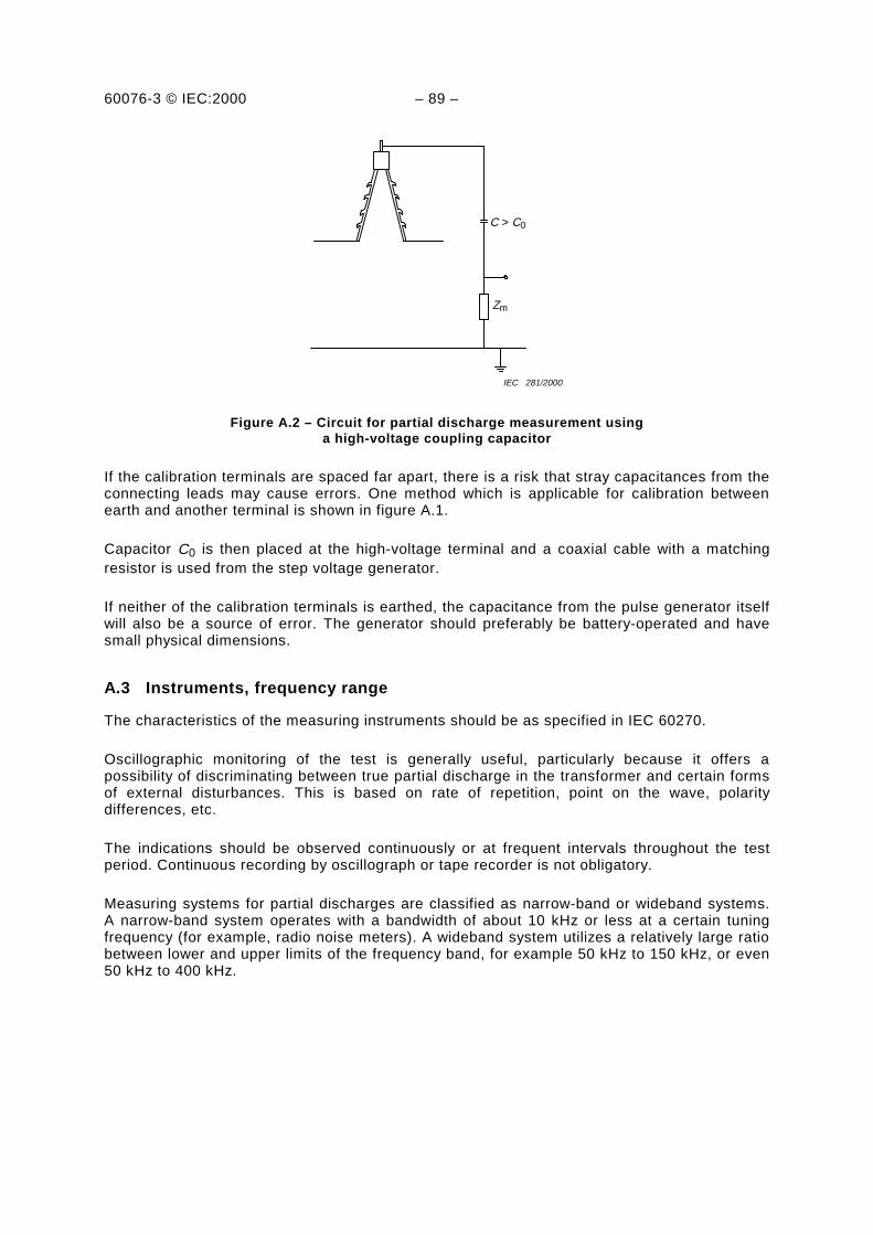
60076-3 © IEC:2000 – 89 –
C > C0
Zm
IEC 281/2000
Figure A.2 – Circuit for partial discharge measurement usinga high-voltage coupling capacitor
If the calibration terminals are spaced far apart, there is a risk that stray capacitances from theconnecting leads may cause errors. One method which is applicable for calibration betweenearth and another terminal is shown in figure A.1.
Capacitor C0 is then placed at the high-voltage terminal and a coaxial cable with a matchingresistor is used from the step voltage generator.
If neither of the calibration terminals is earthed, the capacitance from the pulse generator itselfwill also be a source of error. The generator should preferably be battery-operated and havesmall physical dimensions.
A.3 Instruments, frequency range
The characteristics of the measuring instruments should be as specified in IEC 60270.
Oscillographic monitoring of the test is generally useful, particularly because it offers apossibility of discriminating between true partial discharge in the transformer and certain formsof external disturbances. This is based on rate of repetition, point on the wave, polaritydifferences, etc.
The indications should be observed continuously or at frequent intervals throughout the testperiod. Continuous recording by oscillograph or tape recorder is not obligatory.
Measuring systems for partial discharges are classified as narrow-band or wideband systems.A narrow-band system operates with a bandwidth of about 10 kHz or less at a certain tuningfrequency (for example, radio noise meters). A wideband system utilizes a relatively large ratiobetween lower and upper limits of the frequency band, for example 50 kHz to 150 kHz, or even50 kHz to 400 kHz.

60076-3 © IEC:2000 – 91 –
By the use of a narrow-band system, interference from local broadcasting stations may beavoided by suitably adjusting the mid-band frequency, but a check has to be made to show thatwinding resonances near the measuring frequency do not greatly effect the measurement. Thenarrow-band instrument should be operated at a frequency no higher than 500 kHz, andpreferably less than 300 kHz. There are two reasons for this. First, the transmission of thedischarge pulse entails a high attenuation of the higher frequency components, and second,when applying a calibration pulse to the line terminal, the pulse is likely to excite localoscillations at and near the terminal, and this will complicate the calibration when mid-bandfrequencies greater than 500 kHz are used.
A wideband measuring system is less critical as to attenuation and response to different pulseshapes, but is more receptive to disturbances in test locations without electromagneticshielding. Band-stop filters may be used against radio transmitters. Identification of partialdischarge sources by comparison of shape and polarity of individual pulses may be possible.
NOTE Today's broad-band instruments differ largely in their evaluation modes and built-in filter characteristics.Together with the complicated pulse transfer mode from within the windings and the decaying frequency spectrumof the responses each instrument will yield a different apparent charge reading despite the well-establishedcalibration procedures. The latest revision of IEC 60270 indicates this problem but fails to standardize broad-bandmeasuring instruments. This problem does not exist for narrow-band meters with CISPR 16-1 pulse repetitionevaluation.
A.4 Test criteria – Procedure after an unsuccessful test
At the end of 12.2, 12.3 and 12.4, acceptance criteria are given. The steady-state partialdischarge level, expressed as an apparent charge measured between the prescribedmeasuring terminals, should not be above the specified limit, and there should not be asignificant rising trend during the total test duration.
If there has been no voltage collapse, but the test has been unsuccessful because of too highbut still moderate partial discharge reading (within a few thousand picocoulombs or less), thetest is regarded as non-destructive. A further criterion of importance is that the partialdischarges are not sustained into or below the operating voltage level, when triggered at thetest level.
The test object should not be rejected immediately upon such a result, but furtherinvestigations should be undertaken.
The testing environment should first be investigated to find any obvious sign of irrelevantsources of partial discharges. This should be followed by consultations between the supplierand purchaser to agree on further supplementary tests or other action to show either thepresence of serious partial discharge, or that the transformer is satisfactory for serviceoperation.
Below are some suggestions which may be useful during the above courses of action.
Investigation as to whether the indications are truly correlated to the test sequence or justrepresent coincident, irrelevant sources. This is often facilitated by oscillographicmonitoring of the test, disturbances may for example be identified by their beingasynchronous with the test voltage.

60076-3 © IEC:2000 – 93 –
Investigation as to whether the partial discharge may be transmitted from the supplysource. Low-pass filters on the supply leads to the transformer under test can help in suchcases.
Investigation to determine whether the partial discharge source is within the transformer oroutside (spitting from objects at floating potential in the hall, from live parts in air, or fromsharp edges on earthed parts of the transformer). As the test concerns the internalinsulation, provisional electrostatic shielding on the outside is permitted and recommended.
Investigation of the probable location of the source(s) in terms of the electrical circuitdiagram of the transformer. There are several known and published methods. One is basedon correlation of readings and calibrations at different pairs of terminals (in addition tothe obligatory readings between line terminals and earth). It is described in clause A.5.It is also possible to identify individual pulse shapes during the test with correspondingcalibration waveforms, if records from wideband circuits are used. A particular case is theidentification of partial discharge in the dielectric of the capacitance graded bushings, seeend of clause A.5.
Investigation by acoustic or ultrasonic detection of the "geographical" location of thesource(s) within the tank.
Determination of the probable physical nature of the source by conclusions drawn fromvariation with test voltage level, hysteresis effect, pulse pattern along the test voltage wave,etc.
Partial discharge in the insulation system may be caused by insufficient drying orinsufficient oil impregnation. Re-processing of the transformer, or a period of rest, andsubsequent repetition of the test may therefore be tried.
It is also well known that a limited exposure to a relatively high partial discharge may leadto local cracking of oil and temporarily reduced extinction and re-inception voltages, but thatthe original conditions may be self-restored in a matter of hours.
If the partial discharge indications are above the acceptance limit but are not considered asvery important, it may be agreed to repeat the test, possibly with extended duration, andeven with increased voltage level. Relatively limited variation of the partial discharge levelwith voltage increase, and absence of increase with time, may be accepted as evidencethat the transformer is suitable for service.
Traces of partial discharges visible after untanking are usually not found unless thetransformer has been exposed for a considerable duration of time to levels which are veryhigh in comparison with the acceptance limit. Such a procedure may be the last resort ifother means of improving the behaviour of the transformer or identifying the source havefailed.
A.5 Electrical location of partial discharge sources by means of "multi-terminalmeasurement" and "profile comparison"
An arbitrary partial discharge source will deliver signals at all accessible measuring terminalpairs of the transformer, and the pattern of these signals is a unique "finger-print". If calibrationpulses are fed in at alternative calibration terminal pairs, these pulses also delivercombinations of signals at the measuring pairs.
If there is an evident correlation between the profile of the test readings at different measuringterminal pairs and the profile obtained at the same measuring terminals for pulses fed in at aparticular pair of calibration terminals, then it is assumed that the actual partial dischargesource is closely associated with this calibration pair.
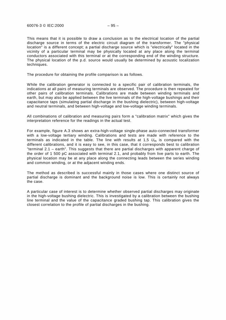
60076-3 © IEC:2000 – 95 –
This means that it is possible to draw a conclusion as to the electrical location of the partialdischarge source in terms of the electric circuit diagram of the transformer. The "physicallocation" is a different concept; a partial discharge source which is "electrically" located in thevicinity of a particular terminal may be physically located at any place along the terminalconductors associated with this terminal or at the corresponding end of the winding structure.The physical location of the p.d. source would usually be determined by acoustic localizationtechniques.
The procedure for obtaining the profile comparison is as follows.
While the calibration generator is connected to a specific pair of calibration terminals, theindications at all pairs of measuring terminals are observed. The procedure is then repeated forother pairs of calibration terminals. Calibrations are made between winding terminals andearth, but may also be applied between the live terminals of the high-voltage bushings and theircapacitance taps (simulating partial discharge in the bushing dielectric), between high-voltageand neutral terminals, and between high-voltage and low-voltage winding terminals.
All combinations of calibration and measuring pairs form a "calibration matrix" which gives theinterpretation reference for the readings in the actual test.
For example, figure A.3 shows an extra-high-voltage single-phase auto-connected transformerwith a low-voltage tertiary winding. Calibrations and tests are made with reference to theterminals as indicated in the table. The line with results at 1,5 Um is compared with thedifferent calibrations, and it is easy to see, in this case, that it corresponds best to calibration"terminal 2.1 – earth". This suggests that there are partial discharges with apparent charge ofthe order of 1 500 pC associated with terminal 2.1, and probably from live parts to earth. Thephysical location may be at any place along the connecting leads between the series windingand common winding, or at the adjacent winding ends.
The method as described is successful mainly in those cases where one distinct source ofpartial discharge is dominant and the background noise is low. This is certainly not alwaysthe case.
A particular case of interest is to determine whether observed partial discharges may originatein the high-voltage bushing dielectric. This is investigated by a calibration between the bushingline terminal and the value of the capacitance graded bushing tap. This calibration gives theclosest correlation to the profile of partial discharges in the bushing.

60076-3 © IEC:2000 – 97 –
Channel 1.1 2.1 2.2 3.1
Calibration Arbitrary units
1.1 – earth 2 000 pC2.1 – earth 2 000 pC2.2 – earth 2 000 pC3.1 – earth 2 000 pC
50523
2050102
530
35035
1084
25
TestU = 0U = Um
U = 1,5 Um
<0,5<0,5
6
<0,5<0,540
<0,50,525
<0,50,58
NOTE For improving effectivity, also terminals 2.2 and 3.2 should be treated asmeasuring and calibration terminals, particularly when capacitance gradedbushings are provided.
Figure A.3 – Location of partial discharge sources by means of"multi-terminal measurement" and "profile comparison"
1.1 2.1 3.1
2.2 3.2
IEC 282/2000
60076-3 © IEC:2000 – 99 –
Annex B(informative)
Overvoltage transferred from the high-voltage winding toa low-voltage winding
B.1 General
The problem of transferred overvoltage is treated from a system viewpoint in annex A ofIEC 60071-2. The information given below concerns only problems associated with thetransformer itself under particular conditions of service. The transferred overvoltages to beconsidered are either transient surges or overvoltages.
NOTE It is the responsibility of the purchaser to define the loading of a low-voltage winding. If no information canbe given, the supplier can provide information about the expected transferred voltages when the low-voltageterminals are open-circuited, and about the values of ohmic resistors or capacitors which are needed to keep thevoltages within acceptable limits.
B.2 Transfer of surge voltage
B.2.1 General
A study of particular transformer installation with regard to transferred surge overvoltages is, ingeneral, justified only for large generator transformers, which have a large voltage ratio, andfor large high-voltage system transformers with a low-voltage tertiary winding.
It is convenient to distinguish between two mechanisms of surge transfer, namely capacitivetransfer and inductive transfer.
B.2.2 Capacitive transfer
The capacitive transfer of overvoltage to a low-voltage winding may in the first approximationbe described as a capacitive voltage division. The simplest equivalent circuit as seen from thelow-voltage winding consists of an electromotive force (e.m.f.) source in series with a transfercapacitance Ct, see figure B.1.
The equivalent e.m.f. is a fraction s of the incoming surge on the high-voltage side. Ct is of theorder of 10–9 F; s and Ct are not well-defined quantities but dependent on the shape of thesurge front. They can be determined together by oscillographic measurements. Pre-calculationis uncertain.
A loading of the secondary terminals with switchgear, short cables or added capacitors (afew nF), which act as lumped capacitance Cs directly on the terminals (even during the firstmicrosecond), will reduce the transferred overvoltage peak. Longer cables or busbars arerepresented by their characteristic impedance. The resulting shape of secondary overvoltagewill normally have the character of a short (microsecond) peak, corresponding to the front ofthe incoming surge.

60076-3 © IEC:2000 – 101 –
Ct
CssU1 ZU2U1
IEC 283/2000 IEC 284/2000
Figure B.1 – Equivalent circuit for capacitive transfer of overvoltage
B.2.3 Inductive transfer
The inductive transfer of surge voltage depends on the flow of surge current in the high-voltagewinding.
If no external loading is applied to the secondary winding, the voltage transient usually has asuperimposed damped oscillation with a frequency determined by leakage inductance andwinding capacitances.
A reduction of the inductively transferred overvoltage component can be effected either byresistive damping through a surge diverter or by modification of the oscillation with capacitiveloading. If capacitors are used, the capacitance value has usually to be of the order of tenths ofmicrofarads. (They will therefore automatically eliminate the capacitively transferredcomponent as long as the circuit inductance is low.)
The transformer parameters which are involved in inductive surge transfer are better definedand less dependent on rate of rise (or frequency) than those involved in capacitive transfer. Forfurther information, see the literature on the subject.
B.3 Power-frequency transferred overvoltage
If a low-voltage winding which is physically adjacent to the high-voltage winding is left withoutconnection to earth or with only a high-impedance connection to earth while the high-voltagewinding is energized, there is a risk of power frequency overvoltage by capacitance division.
The risk is obvious for a single-phase winding, but it can also exist for a three-phase winding ifthe primary winding voltage becomes asymmetric, as occurs during earth faults. In particularcircumstances, resonance conditions may arise.
Tertiary windings and stabilizing windings in large transformers are also subjected to the samerisk. It is the responsibility of the purchaser to prevent a tertiary winding from being accidentallyleft with too high an impedance to earth. A stabilizing winding should normally be arranged forpermanent connection to earth (tank) either externally or internally.
The overvoltage is determined by capacitances between windings and between windings andearth. These can be measured at low frequency from the terminal of the transformer indifferent combinations, and they can also be calculated with sufficient accuracy.

60076-3 © IEC:2000 – 103 –
Annex C(informative)
Information on transformer insulation and dielectric teststo be supplied with an enquiry and with an order
For all windings:
− Value of Um for the line terminals and the assigned Um for the neutral terminals.
− Connection of the windings (Y, D or zig-zag).
− Rated withstand voltages constituting the insulation level for line terminals, see table 1.
− Whether the winding is to have uniform or non-uniform insulation, and in the case of non-uniform insulation, the AC withstand voltages of the neutral.
− Whether a rated impulse withstand level is assigned to the neutral, and, in such a case, theappropriate withstand voltage.
− Whether the lightning impulse test on the line terminals is to include a chopped impulse test.
For transformers having a high-voltage winding with Um = 245 kV:
– Whether the switching impulse test is to be omitted (only if the short-duration AC inducedwithstand test is specified, see table 1).
For transformers having a high-voltage winding with Um ≥ 245 kV:
– If the short-duration induced test is specified, the procedure for performing the test foruniform insulation according to 12.2 and for non-uniform insulation according to 12.3 shouldbe specified.
It is further recommended that test connections and procedures should be discussed at thetime of placing the order or at the design review stage, particularly with regard to theconnection for induced withstand voltage tests on complicated transformers with non-uniformlyinsulated high-voltage windings (see 12.3, note) and the method to be used for impulse testson high-power low-voltage windings and neutral terminals (see 13.3). The application of non-linear protection devices, built into the transformer is to be indicated by the supplier atthe enquiry and at the order stage, and should be shown in the connection diagram at therating plate.
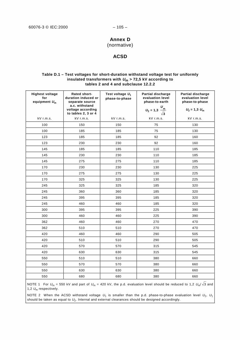
60076-3 © IEC:2000 – 105 –
Annex D(normative)
ACSD
Table D.1 – Test voltages for short-duration withstand voltage test for uniformlyinsulated transformers with Um > 72,5 kV according to
tables 2 and 4 and subclause 12.2.2
Highest voltagefor
equipment Um
Rated short-duration induced or
separate sourcea.c. withstand
voltage accordingto tables 2, 3 or 4
Test voltage U1
phase-to-phasePartial dischargeevaluation levelphase-to-earth
U2 = 1,3 3
mU
Partial dischargeevaluation levelphase-to-phase
U2 = 1,3 Um
kV r.m.s. kV r.m.s. kV r.m.s. kV r.m.s. kV r.m.s.
100 150 150 75 130
100 185 185 75 130
123 185 185 92 160
123 230 230 92 160
145 185 185 110 185
145 230 230 110 185
145 275 275 110 185
170 230 230 130 225
170 275 275 130 225
170 325 325 130 225
245 325 325 185 320
245 360 360 185 320
245 395 395 185 320
245 460 460 185 320
300 395 395 225 390
300 460 460 225 390
362 460 460 270 470
362 510 510 270 470
420 460 460 290 505
420 510 510 290 505
420 570 570 315 545
420 630 630 315 545
550 510 510 380 660
550 570 570 380 660
550 630 630 380 660
550 680 680 380 660
NOTE 1 For Um = 550 kV and part of Um = 420 kV, the p.d. evaluation level should be reduced to 1,2 Um/ 3 and1,2 Um respectively.
NOTE 2 When the ACSD withstand voltage U1 is smaller than the p.d. phase-to-phase evaluation level U2, U1
should be taken as equal to U2. Internal and external clearances should be designed accordingly.
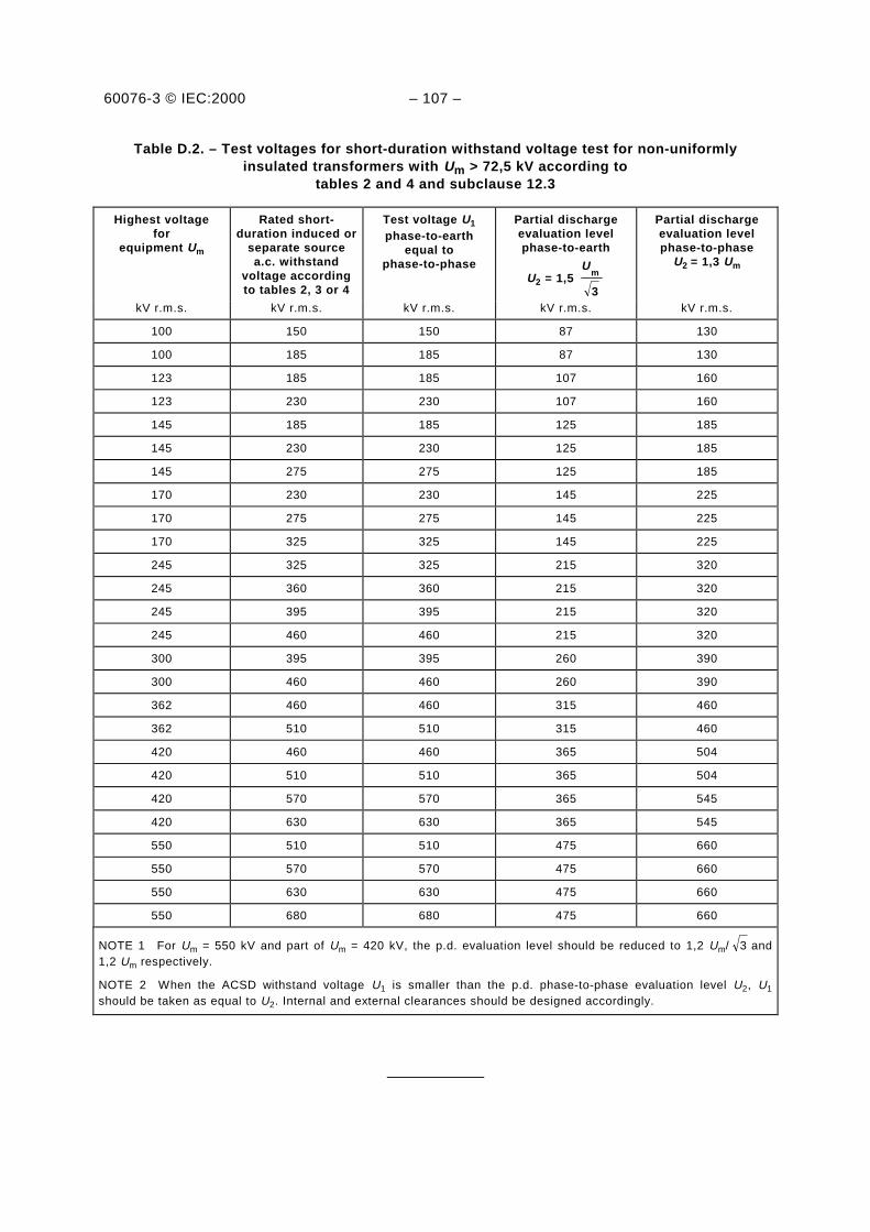
60076-3 © IEC:2000 – 107 –
Table D.2. – Test voltages for short-duration withstand voltage test for non-uniformlyinsulated transformers with Um > 72,5 kV according to
tables 2 and 4 and subclause 12.3
Highest voltagefor
equipment Um
Rated short-duration induced or
separate sourcea.c. withstand
voltage accordingto tables 2, 3 or 4
Test voltage U1
phase-to-earthequal to
phase-to-phase
Partial dischargeevaluation levelphase-to-earth
U2 = 1,5 3
mU
Partial dischargeevaluation levelphase-to-phase
U2 = 1,3 Um
kV r.m.s. kV r.m.s. kV r.m.s. kV r.m.s. kV r.m.s.
100 150 150 87 130
100 185 185 87 130
123 185 185 107 160
123 230 230 107 160
145 185 185 125 185
145 230 230 125 185
145 275 275 125 185
170 230 230 145 225
170 275 275 145 225
170 325 325 145 225
245 325 325 215 320
245 360 360 215 320
245 395 395 215 320
245 460 460 215 320
300 395 395 260 390
300 460 460 260 390
362 460 460 315 460
362 510 510 315 460
420 460 460 365 504
420 510 510 365 504
420 570 570 365 545
420 630 630 365 545
550 510 510 475 660
550 570 570 475 660
550 630 630 475 660
550 680 680 475 660
NOTE 1 For Um = 550 kV and part of Um = 420 kV, the p.d. evaluation level should be reduced to 1,2 Um/ 3 and1,2 Um respectively.
NOTE 2 When the ACSD withstand voltage U1 is smaller than the p.d. phase-to-phase evaluation level U2, U1
should be taken as equal to U2. Internal and external clearances should be designed accordingly.
____________

ICS 29.180
Typeset and printed by the IEC Central OfficeGENEVA, SWITZERLAND
ISBN 2-8318-5191-2

EAS 371-3:2005
© EAC 2005 — All rights reserved