basics of heat exchangers - · pdf filefeatures of fixed tube-sheet heat exchangers low cost...
TRANSCRIPT

Basics of Basics of
Heat ExchangersHeat Exchangers

Classification of Heat Exchanger Classification of Heat Exchanger based on dutybased on duty
HeaterHeaterCoolerCooler
CondenserCondenserVaporizerVaporizer

Types of Heat ExchangerTypes of Heat Exchanger
Double Pipe Heat Exchanger Shell and Tube Heat ExchangerU-tube Heat ExchangerPlate type Heat ExchangerSpiral Heat ExchangerFinned Tube Heat Exchanger
New DevelopmentsMicro Heat Exchanger
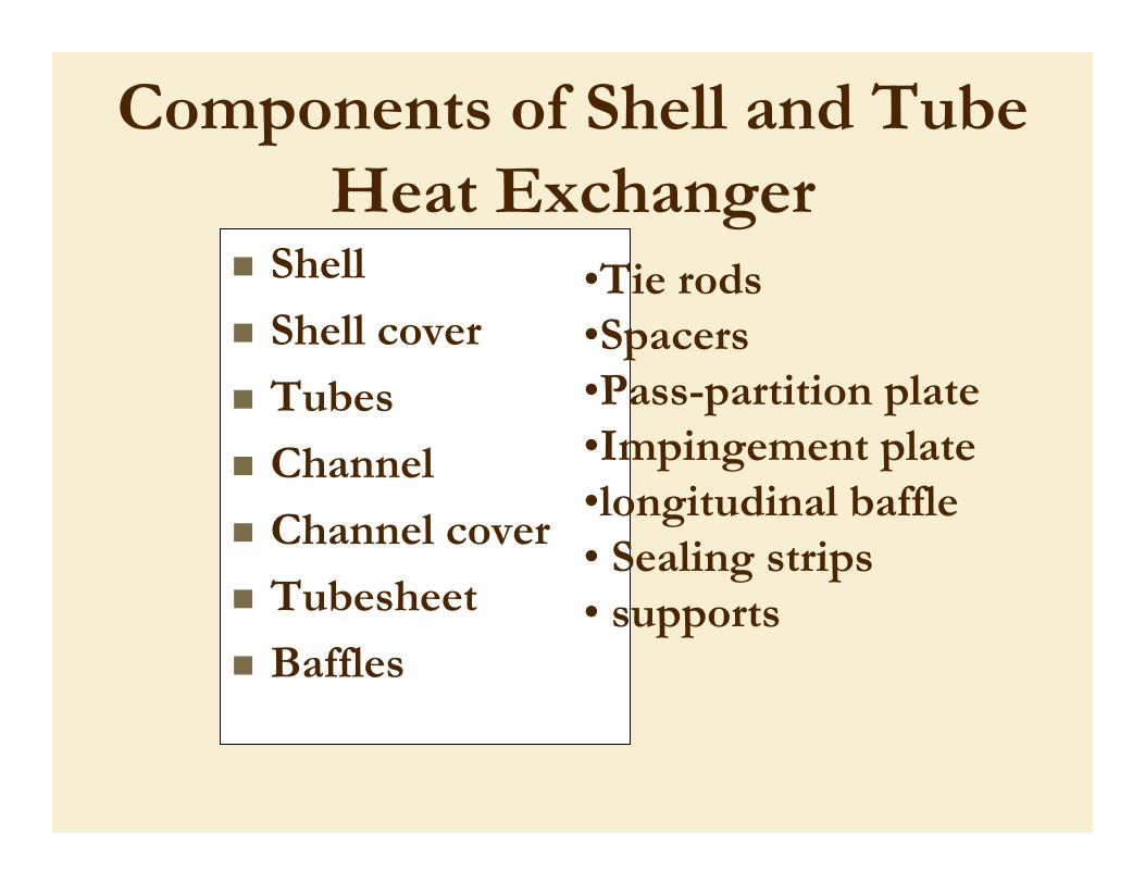
Shell
Shell cover
Tubes
Channel
Channel cover
Tubesheet
Baffles
Components of Shell and Tube Heat Exchanger
•Tie rods •Spacers•Pass-partition plate•Impingement plate•longitudinal baffle• Sealing strips • supports
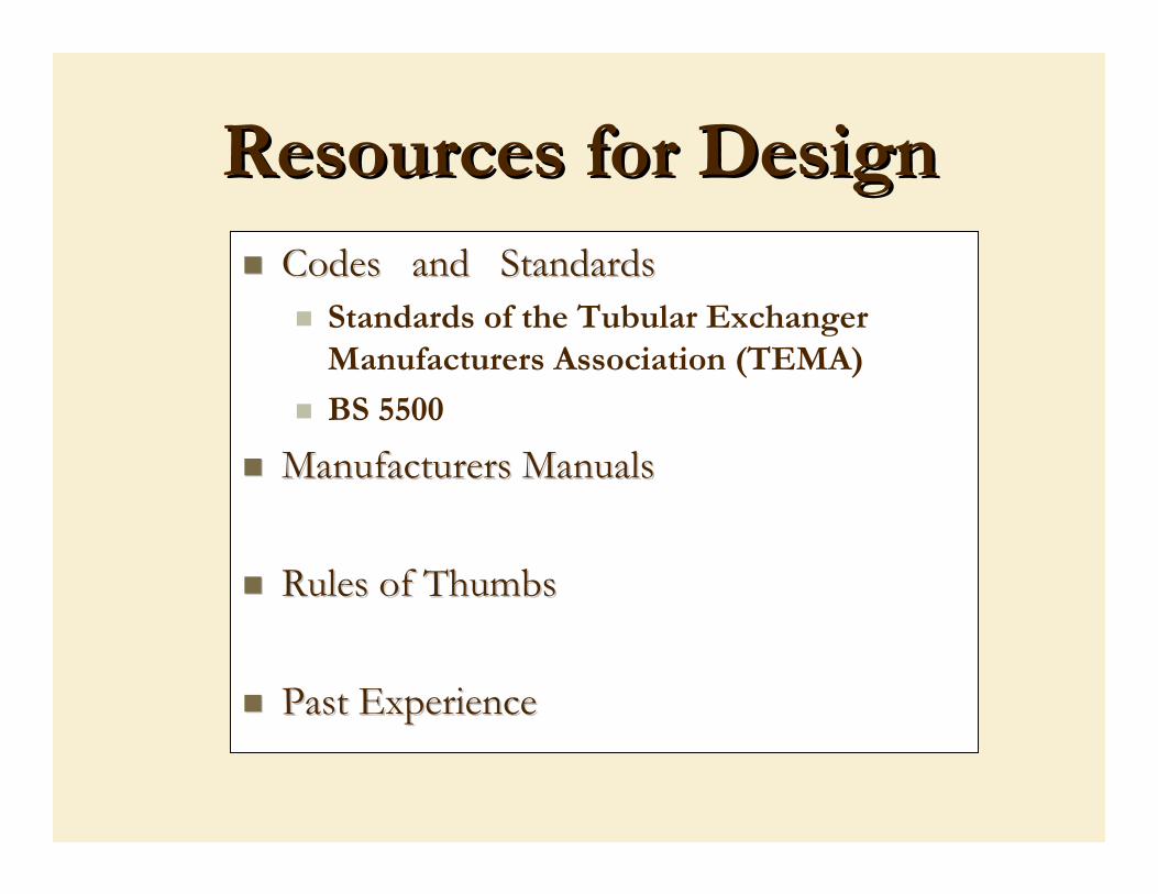
Resources for DesignResources for DesignCodes and StandardsCodes and Standards
Standards of the Tubular Exchanger Manufacturers Association (TEMA)
BS 5500
Manufacturers ManualsManufacturers Manuals
Rules of ThumbsRules of Thumbs
Past ExperiencePast Experience
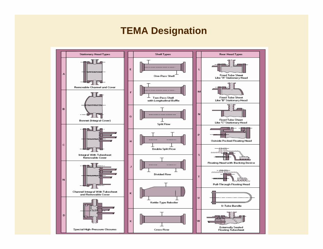
TEMA Designation

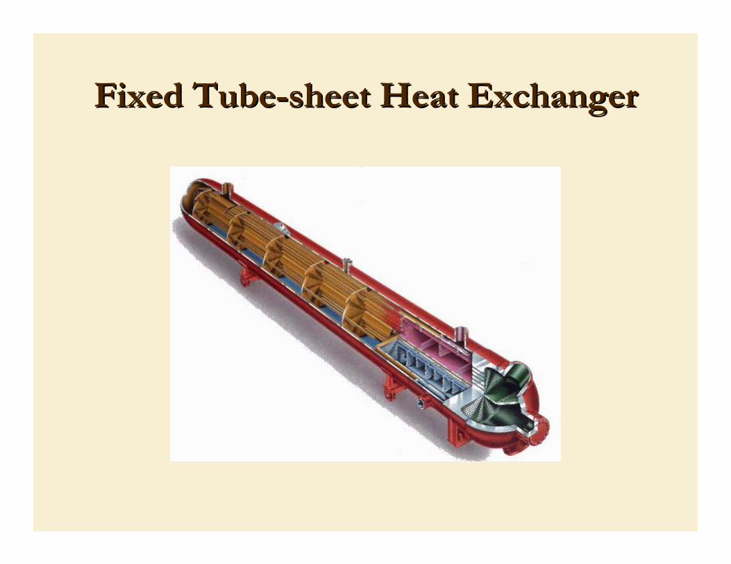
Fixed tubesheetA fixed-tubesheet heat exchanger has straight
tubes that are secured at both ends to tubesheets welded to the shell.
The construction may haveremovable channel covers (e.g., AEL)
bonnet-type channel covers (e.g., BEM)
integral tubesheets (e.g., NEN)
ClassificationClassificationbased on constructionbased on construction

Features of Fixed TubeFeatures of Fixed Tube--sheetsheetHeat ExchangersHeat Exchangers
Low cost because of its simple construction. The fixed tubesheet is the least expensive Construction type, as long as no expansion joint is required.Tubes can be cleaned mechanically after removal of the channel cover or bonnetLeakage of the shell side fluid is minimized since there are no flanged joints.In the event of a large differential temperature between the tubes and the shell, the tubesheets will be unable to absorb the differential stress, thereby making it necessary to incorporate an expansion joint. This takes away the advantage of low cost to a significant extent.Disadvantage of this design is that since the bundle is fixed tothe shell and cannot be removed, the outsides of the tubes cannot be cleaned mechanically. Its application is limited to clean services on the shell side.

Fixed TubeFixed Tube--sheet Heat Exchangersheet Heat Exchanger
Fixed TubeFixed Tube--sheet Heat Exchangersheet Heat Exchanger
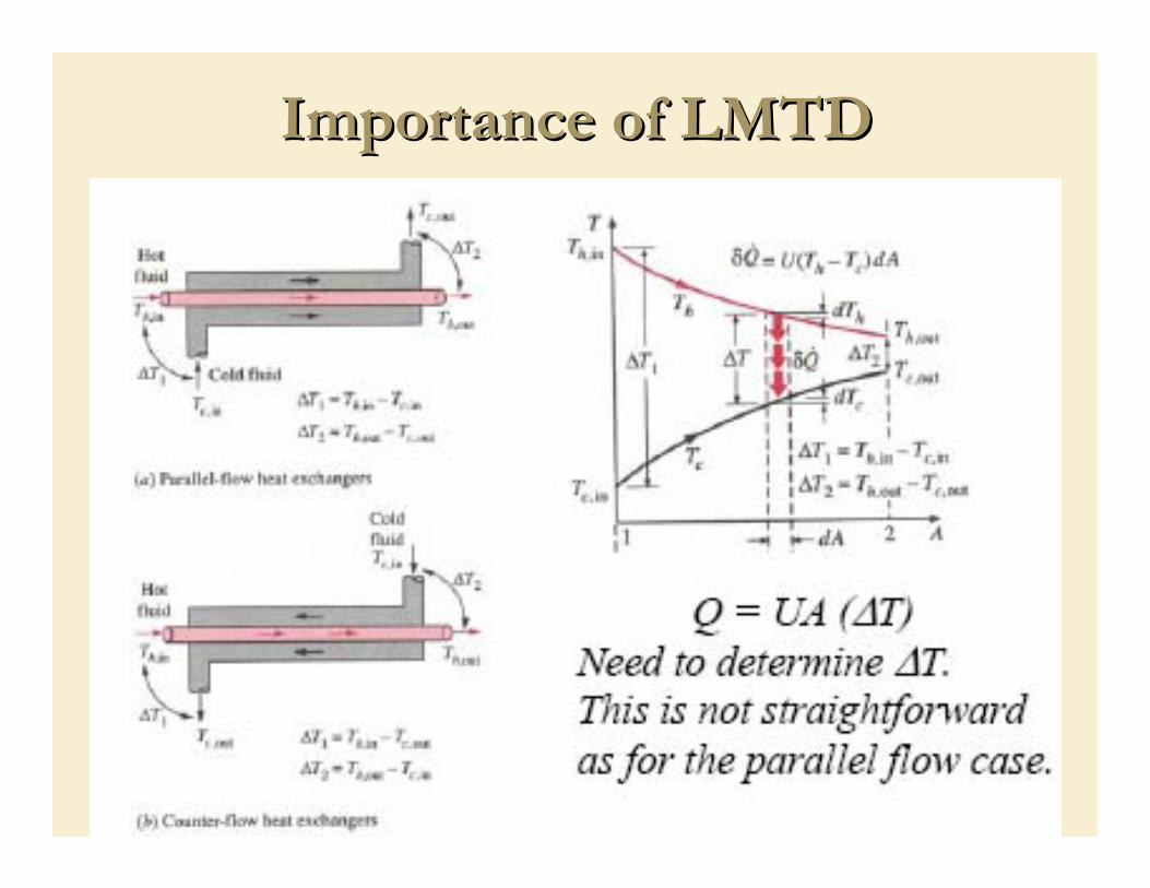
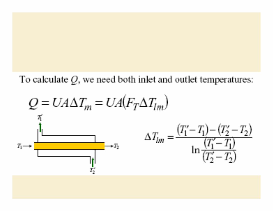
Importance of LMTDImportance of LMTD

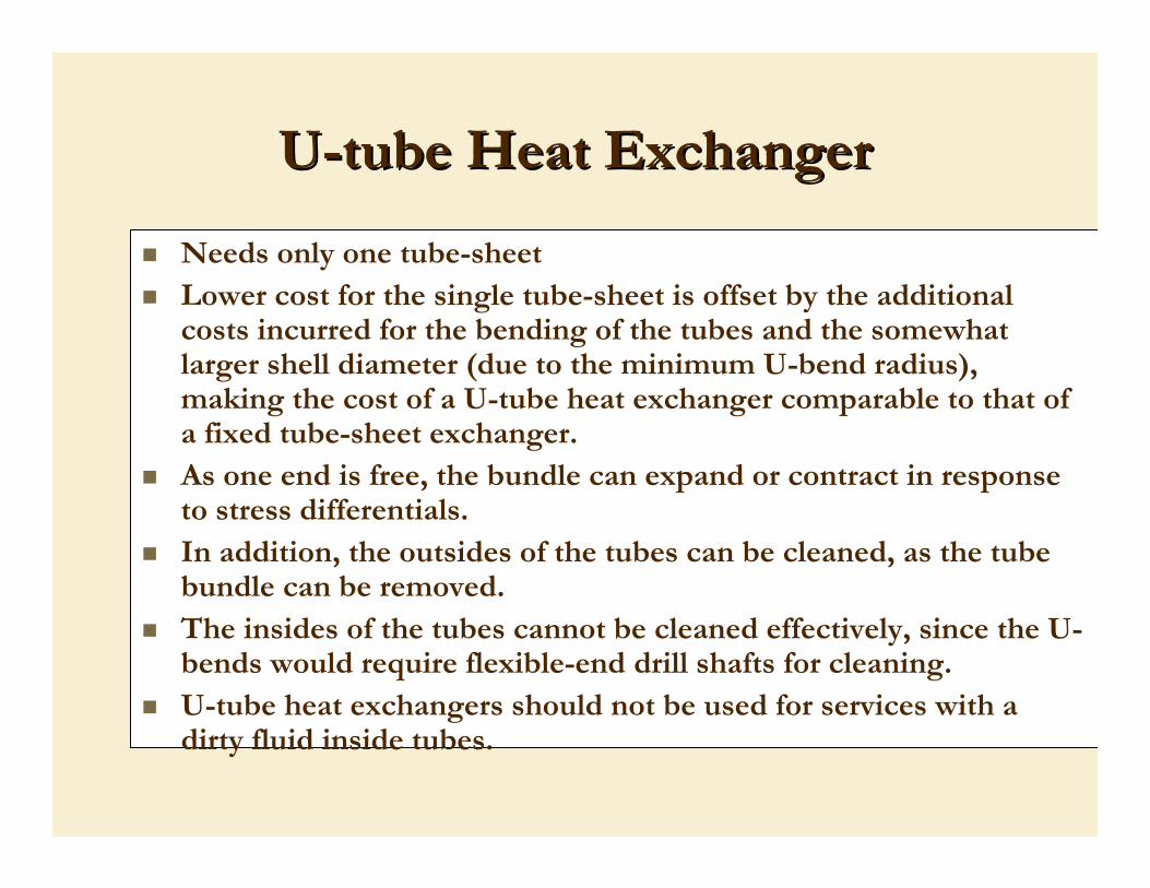
UU--tube Heat Exchangertube Heat Exchanger
Needs only one tube-sheetLower cost for the single tube-sheet is offset by the additional costs incurred for the bending of the tubes and the somewhat larger shell diameter (due to the minimum U-bend radius), making the cost of a U-tube heat exchanger comparable to that of a fixed tube-sheet exchanger.As one end is free, the bundle can expand or contract in response to stress differentials.In addition, the outsides of the tubes can be cleaned, as the tube bundle can be removed.The insides of the tubes cannot be cleaned effectively, since the U-bends would require flexible-end drill shafts for cleaning.U-tube heat exchangers should not be used for services with a dirty fluid inside tubes.

UU--tube Heat Exchangertube Heat Exchanger

Double Tube SheetsDouble Tube Sheets

Arrangements of BafflesArrangements of Baffles

Pass PartitionsPass Partitions
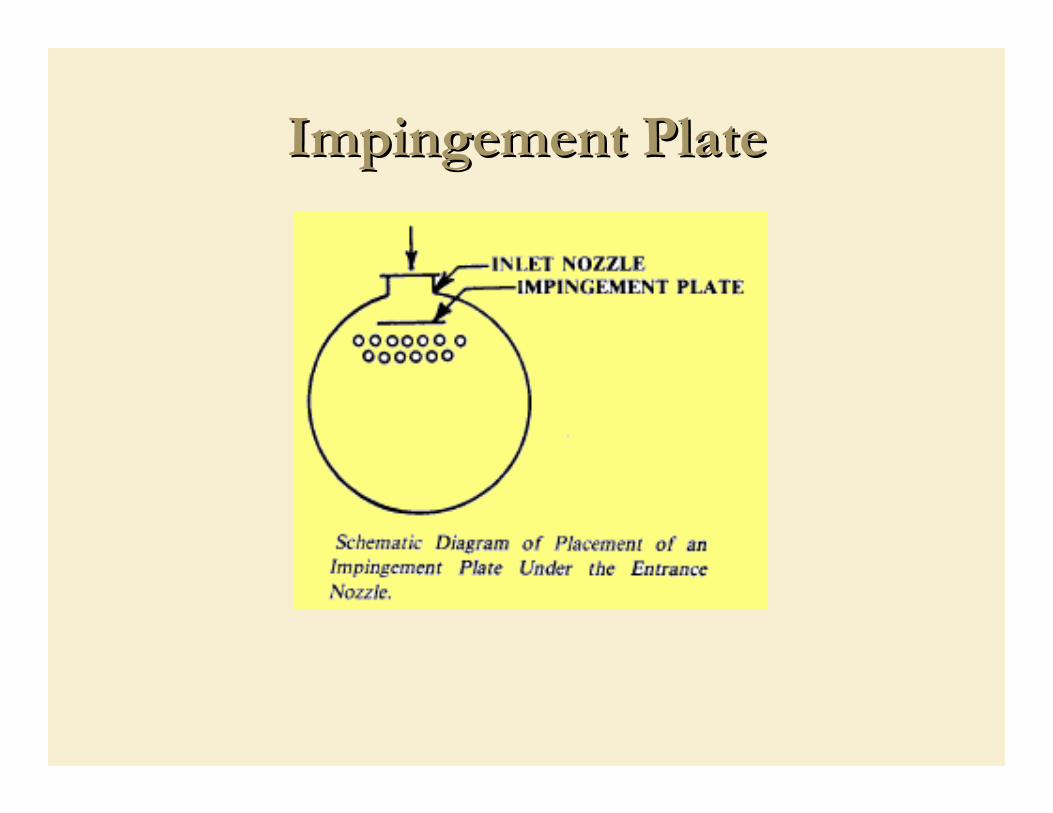
Impingement PlateImpingement Plate
Design Strategy for Controlling Shell Design Strategy for Controlling Shell and Tube Heat Exchangersand Tube Heat Exchangers
Trouble due to processFluctuations in the heat demand of the process
SolutionHeat exchanger must be designed for the worst case and must be controlled to make it operate at the particular rate required by the process at every moment in time.
Design Strategy for Controlling Shell Design Strategy for Controlling Shell and Tube Heat Exchangersand Tube Heat Exchangers
Trouble due to toolCharacteristics of heat exchanger changes with time.FoulingVibration in tubesLower heat transfer coefficient
SolutionThe most common change is a reduction in the heat transfer rate due to fouling of the surfaces. Exchangers are initially oversized to allow for the fouling which gradually builds up during use until the exchanger is no longer capable of performing its duty.Once it has been cleaned it is again oversized.

Design Strategy for Controlling Shell Design Strategy for Controlling Shell and Tube Heat Exchangersand Tube Heat Exchangers
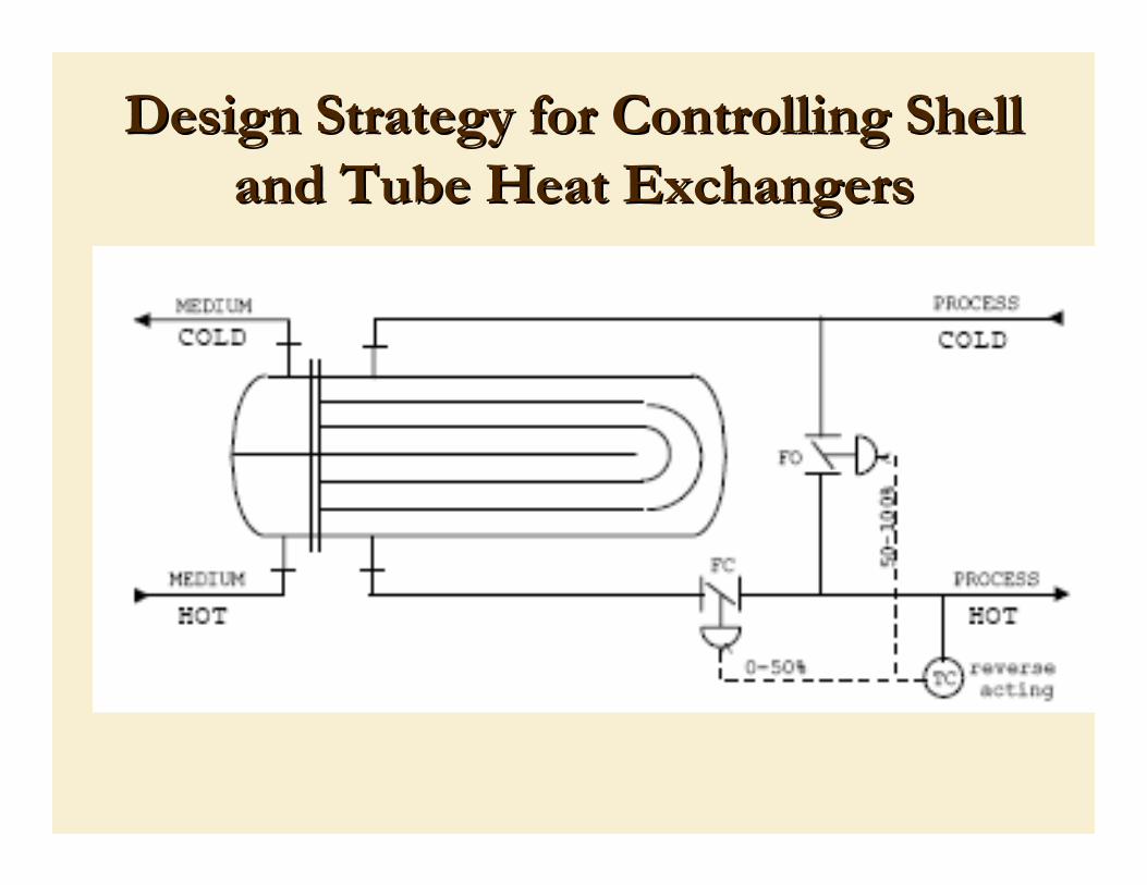
Bypassing The Process FluidProcess temperature can be controlled by manipulating process flow if a bypass is installed.
As the outlet temperature rises in case of a heater, more fluid is bypassed around the ex-changer without being heated.
As the two streams are blended together again, the correct temperature is achieved.

Design Strategy for Controlling Shell Design Strategy for Controlling Shell and Tube Heat Exchangersand Tube Heat Exchangers
Split Range: Tricks For Bypassing / Manipulation
Arranging the valve controls
Attempt to minimize pressure drop at all times, or Attempt to keep the pressure drop constant.
In neither case interruption in the the total flow is acceptable.
To minimize pressure drop, a butterfly valve is the likeliest choice.
Design Strategy for Controlling Shell Design Strategy for Controlling Shell and Tube Heat Exchangersand Tube Heat Exchangers

Design Strategy for Controlling Shell Design Strategy for Controlling Shell and Tube Heat Exchangersand Tube Heat ExchangersProblem : Wide open butterfly has some pressure drop. It may be
greater than that of the heat exchanger itself.This means that even when the valve is wide open only half the flow, or less, will bypass the exchanger.
Solution:To accomplish a greater degree of bypass, a restriction must be placed on the flow through the exchanger. The restriction should be adjustable since conditions change and we do not want more restriction than necessary. The easiest way to do this is with a hand valve. Since these valves are often in relatively inaccessible places, remote actuators may be added. Once that is done it becomes an obvious matter to arrange automatic controls so that once the bypass is fully open, the restriction valve starts to close, andvice versa.
Medium Side ThrottlingAvoid using a process side bypass valve with fluids that are
being heated and have a tendency to break down or scorch. These include many food products and also petroleum products or other chemicals that may polymerize or coke at high temperatures. The problem is that the outlet temperature is a blend of the bypass stream and the stream through the heater. The peak temperature to which any part of the stream is exposed may considerably exceed that of the combined outlet.

Hot oil is being supplied to heat a process stream. It is desired to keep the process stream at a constant temperature. There is no reason to maintain the flow of oil in excess of what is needed -- it can be throttled to control the temperature. In this case the valve is placed on the outlet of the exchanger.
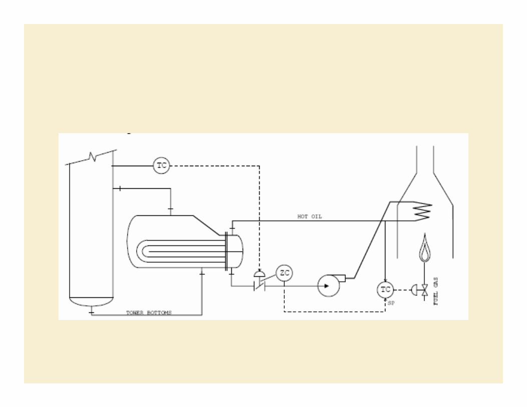
Advanced Control StrategyAdvanced Control Strategy
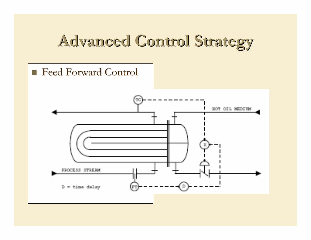
Feed Forward ControlFeed Forward Control
It is required to keep the temperature at the bottom of the tower constant. The heating medium is hot oil which is being heated by a fired heater and circulated by a pair of pumps. Since the tower bottoms is being boiled, and is also very clean, it goes on the shell side. The oil goes through the tube side where the outlet is throttled by a butterfly valve. A position transmitter has been added to the valve. Its output goes to a Position Controller with a setpointof about 80% open. The output of the Position Controller is cascaded to the setpoint of the Temperature Controller of the furnace. The effect is to maintain the furnace, and the hot oil, at the lowest temperature consistent with the heat demand of the tower. It works as follows: a) As the heat demand rises, the valve opens further. b) When the valve is open beyond 75%, the setpoint to the furnace Temperature Controller is raised. c) As the temperature of the hot oil rises, the valve closes to near the 75% value. d) As the heat demand of the tower falls, the valve closes below 75%. e) As the valve closes, the setpoint to the furnace is lowered until the valve is once again at its 75 % target.