basics of mechanical engineering labbasics of mechanical engineering lab . experiment no-1 aim: to...
TRANSCRIPT

BASICS OF MECHANICAL
ENGINEERING LAB

EXPERIMENT NO-1
AIM: To study the working and function of mounting & accessories in boiler.
APPARATUS USED: Model of Mounting & accessories in boiler.
THEORY: For efficient operation and maintenance of safety, the boiler equipped with two categories of components
and elements.
First categories include the fittings which are primarily indicated for the safety of the boiler and for complete control
the process of steam generation. These units are called mountings. The mounting from an integral part of the boiler
and are mounted on the body of the boiler itself. The following mountings are usually installed on the boiler.
1. Two safety valve
2. Two water level indicators
3. Pressure gauge
4. Fusible plug
5. Steam stop valve
6. Feed check valve
7. Blow-of cock
8. Man and mud hole
Second categories include the components which are installed to increase the efficiency of the steam power plants
and help in the power working of the boiler unit. These fitting are called boiler accessories. The following accessories
are given below.
1. Air pre-heater
2. Economiser
3. Super heater
4. Feed pump and
5. Injector
FUNCTION, LOCATION AND WORKING OF MOUNTINGS AND ACCESSORIES.
A) SAFETY VALVE: The function of the safety valve is to permit the steam in the boiler to escape to atmosp0here
when pressure in the steam space in the boiler. The safety valve operates in the principle that a valve is pressed
against its seat through some agency such as sturt, screw or spring by external weight or force, when the steam force
due to boiler pressure acting under the valve exceeds the external force, the valve gets lifted off its seat and some of
the steam rushes out until normal pressure is restored again.
The commonly used safety valves are given below:
ii) Lever safety valve
iii) Spring loaded safety valve
iv) High steam-low water safety valve
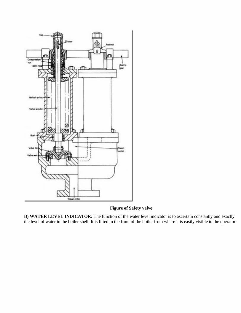
Figure of Safety valve
B) WATER LEVEL INDICATOR: The function of the water level indicator is to ascertain constantly and exactly
the level of water in the boiler shell. It is fitted in the front of the boiler from where it is easily visible to the operator.
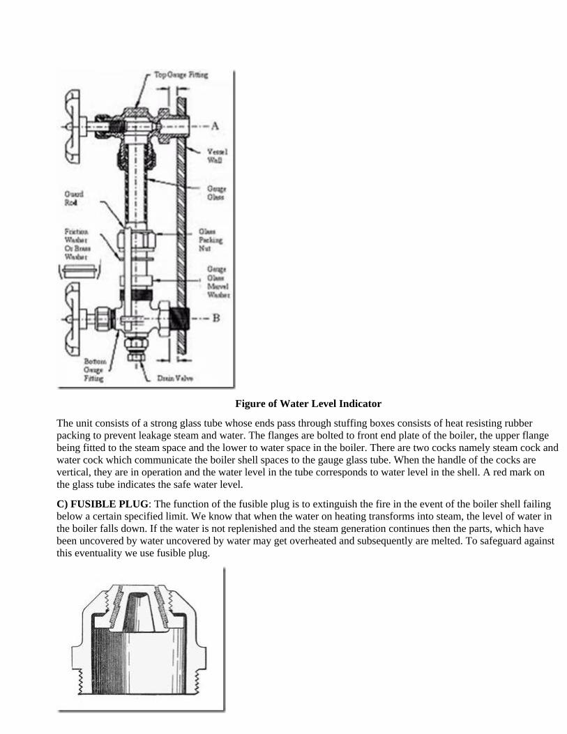
Figure of Water Level Indicator
The unit consists of a strong glass tube whose ends pass through stuffing boxes consists of heat resisting rubber
packing to prevent leakage steam and water. The flanges are bolted to front end plate of the boiler, the upper flange
being fitted to the steam space and the lower to water space in the boiler. There are two cocks namely steam cock and
water cock which communicate the boiler shell spaces to the gauge glass tube. When the handle of the cocks are
vertical, they are in operation and the water level in the tube corresponds to water level in the shell. A red mark on
the glass tube indicates the safe water level.
C) FUSIBLE PLUG: The function of the fusible plug is to extinguish the fire in the event of the boiler shell failing
below a certain specified limit. We know that when the water on heating transforms into steam, the level of water in
the boiler falls down. If the water is not replenished and the steam generation continues then the parts, which have
been uncovered by water uncovered by water may get overheated and subsequently are melted. To safeguard against
this eventuality we use fusible plug.

Figure of Fusible Plug
The fusible plug is inserted at the box crown or cover the combustion chamber at the lowest permissible water level.
D) PRESSURE GAUGE: Each boiler has to be provided with a pressure gauge, which record the pressure at which
the steam is being generated in the boiler.
Figure of Pressure gauge
The gauge is usually mounted at the front top of the boiler shell or drum. The gauge should to be clearly visible to the
attendant so that he can easily record the pressure reading.
E) BLOW OFF COCK: The blow of cock serves to drain out the water from the boiler periodically for any one of
the following reasons:
1) To discharge mud, scale and other impurities which settle down at the bottom of the boiler?
2) To empty the boiler for internal cleaning and inspection.
3) To lower the water level rapidly if the level becomes too high.
The unit is fitted at the lowest portion of the boiler. It may be mounted directly to the boiler shell or through an boiler
elbow pipe, which is fitted to the boiler shell.
F) FEED CHECK VALVE: The feed check valve has the following two functions to perform:
1. To allow the feed water to pass into the boiler.
2. To prevent the back flow of water from the boiler in the events of the failure of the feed pump.

Figure of Feed check Valve
G) STOP VALVE: The function of the steam stop valve is to shut off or regulate the flow of steam from the boiler
to the steam pipe or from the steam pipe to the engine. When used for the former purpose, it is called junction valve.
Usually the junction valve means a regulating valve of larger size and a stop valve refers to a regulating valve of
smaller size.
Figure of Stop valve
The junction valve is mounted on the highest part of the steam space of the boiler and is connected to the steam pipe,
which carries the steam to the engine.
H) MAN HOLES: These are door to allow men to enter inside the boiler for the inspection and repair
I) AIR PREHEATER: Air heater or air pre-heater is waste heat recovery device in which the air on its way to the
furnace is raised in temperature by utilizing the heat of the exhaust gases. Air pre-heater are classified into the
following two categories.
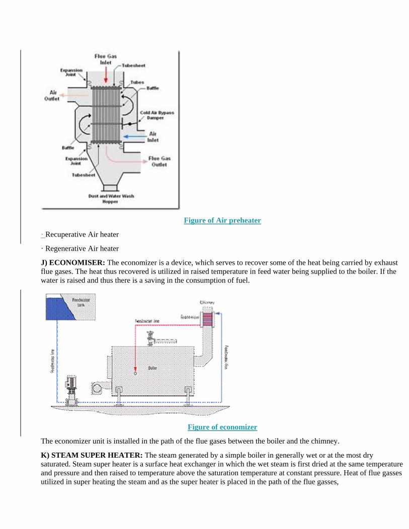
Figure of Air preheater
· Recuperative Air heater
· Regenerative Air heater
J) ECONOMISER: The economizer is a device, which serves to recover some of the heat being carried by exhaust
flue gases. The heat thus recovered is utilized in raised temperature in feed water being supplied to the boiler. If the
water is raised and thus there is a saving in the consumption of fuel.
Figure of economizer
The economizer unit is installed in the path of the flue gases between the boiler and the chimney.
K) STEAM SUPER HEATER: The steam generated by a simple boiler in generally wet or at the most dry
saturated. Steam super heater is a surface heat exchanger in which the wet steam is first dried at the same temperature
and pressure and then raised to temperature above the saturation temperature at constant pressure. Heat of flue gasses
utilized in super heating the steam and as the super heater is placed in the path of the flue gasses,
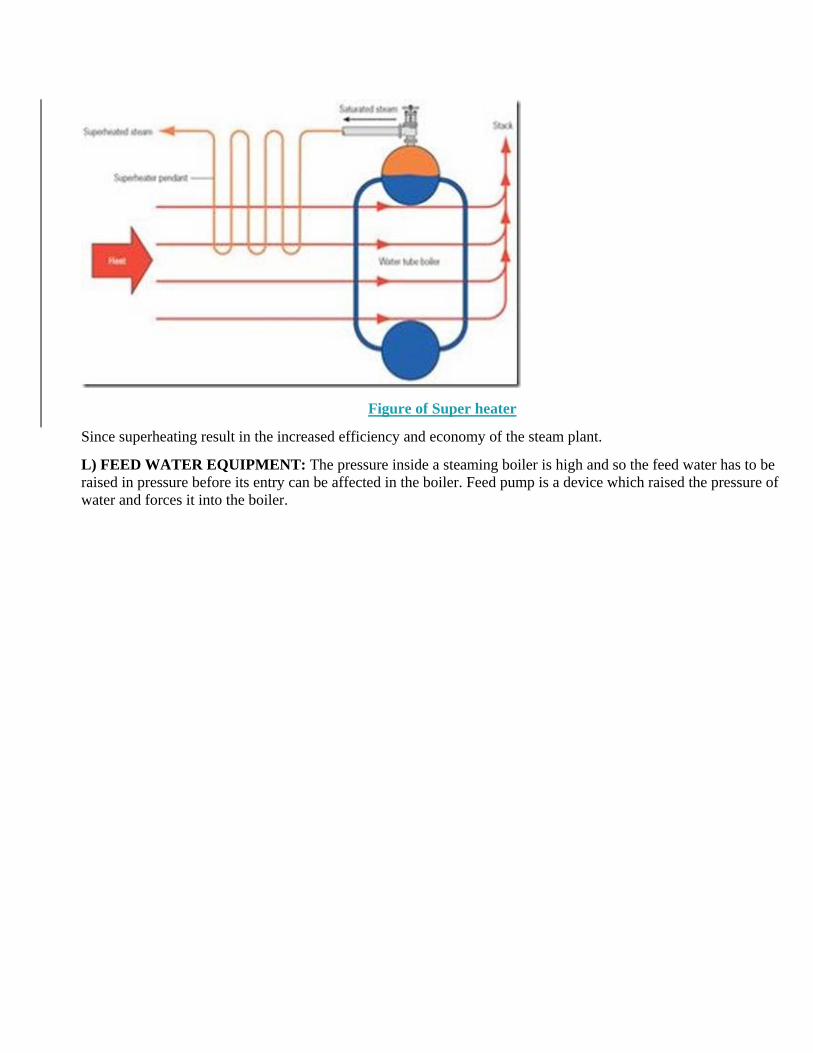
Figure of Super heater
Since superheating result in the increased efficiency and economy of the steam plant.
L) FEED WATER EQUIPMENT: The pressure inside a steaming boiler is high and so the feed water has to be
raised in pressure before its entry can be affected in the boiler. Feed pump is a device which raised the pressure of
water and forces it into the boiler.
EXPERIMENT NO-2
Aim:To study the performance of differential axle and wheel and find its velocity ratio,
efficiency and law of machine etc…
Apparatus: Differential axle and wheel consisting of effort wheel, larger axle, smaller axle,
thread, pan, weights
Theory:
i. Parts of machine: Differential axle and wheel consisting of effort wheel,
larger axle and smaller axle.
ii. Working of machine: The load axle is made up of two parts to the same shaft
which is mounted on the shaft ball bearing in order to reduce the frictional
resistance. The effort string is wound around the axle to which the effort pan is
attached.
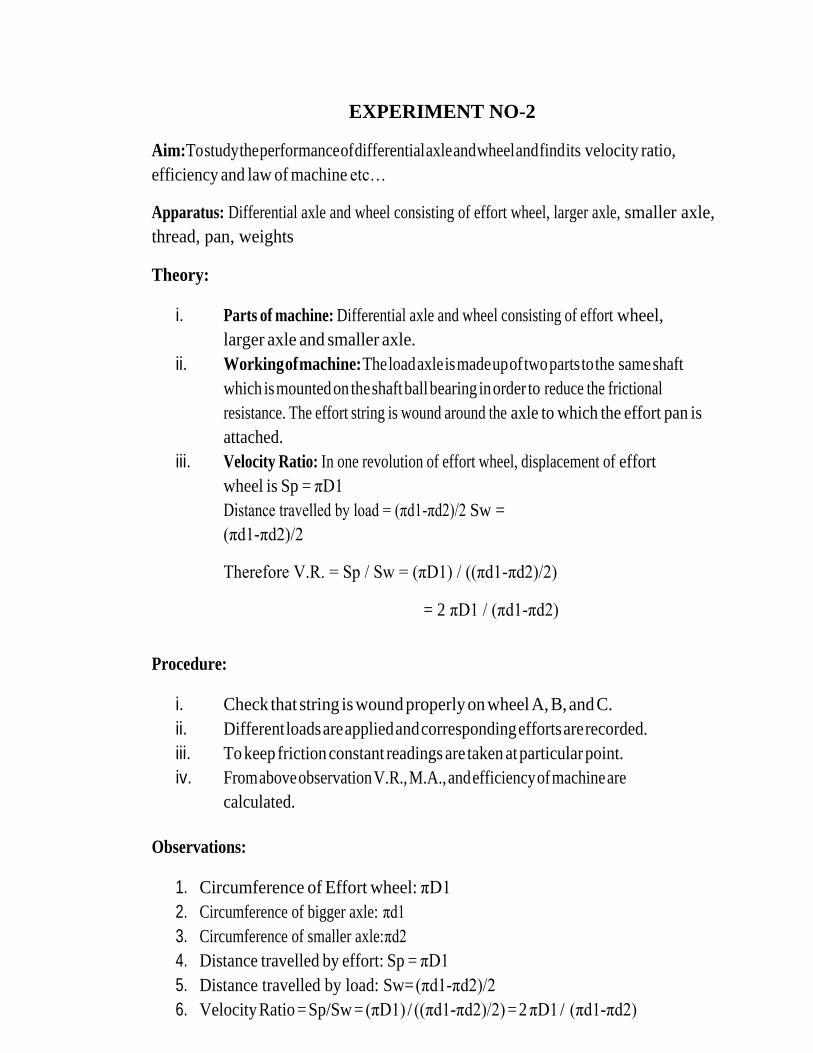
iii. Velocity Ratio: In one revolution of effort wheel, displacement of effort
wheel is Sp = πD1
Distance travelled by load = (πd1-πd2)/2 Sw =
(πd1-πd2)/2
Therefore V.R. = Sp / Sw = (πD1) / ((πd1-πd2)/2)
= 2 πD1 / (πd1-πd2)
Procedure:
i. Check that string is wound properly on wheel A, B, and C.
ii. Different loads are applied and corresponding efforts are recorded.
iii. To keep friction constant readings are taken at particular point.
iv. From above observation V.R., M.A., and efficiency of machine are
calculated.
Observations:
1. Circumference of Effort wheel: πD1
2. Circumference of bigger axle: πd1
3. Circumference of smaller axle: πd2
4. Distance travelled by effort: Sp = πD1
5. Distance travelled by load: Sw= (πd1-πd2)/2
6. Velocity Ratio = Sp/Sw = (πD1) / ((πd1-πd2)/2) = 2 πD1 / (πd1-πd2)
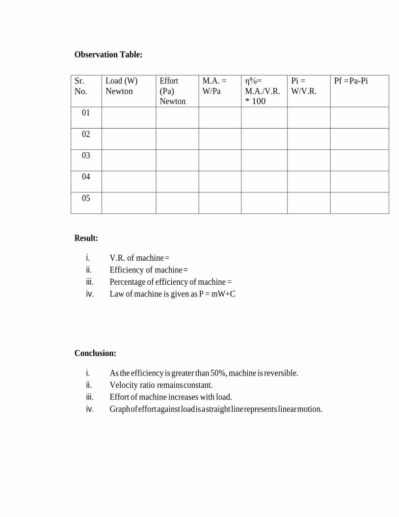
Observation Table:
Sr.
No.
Load (W)
Newton
Effort
(Pa) Newton
M.A. =
W/Pa
η%=
M.A./V.R. * 100
Pi =
W/V.R. Pf = Pa-Pi
01
02
03
04
05
Result:
i. V.R. of machine =
ii. Efficiency of machine =
iii. Percentage of efficiency of machine =
iv. Law of machine is given as P = mW+C
Conclusion:
i. As the efficiency is greater than 50%, machine is reversible.
ii. Velocity ratio remains constant.
iii. Effort of machine increases with load.
iv. Graph of effort against load is a straight line represents linear motion.
EXPERIMENT NO-3
Aim: To find moment of inertia of flywheel
Apparatus: Flywheel mounted on axle and supported by bearing, pan, weights, and stop watch.
Theory:
Moment of Inertia is the property of the body by virtue of which it resists the change in the state
of its angular motion about any axis. It depends upon the mass of the body and the distance
with respect to axis of rotation.
For falling mass, Initial
velocity = v = 0 Height of
fall = h
a= 2h/t2
Resultant force = T-mg
-F = T-mg
-ma = T-mg T
=m(g-a)
Moment ‘M’ = Iα
T*r = I *a/r (since a= rα) I =Tr2/a
I = m (g – a) r2 / a
Procedure:
Attach a long thread about 1.8 m length to the axle of flywheel and end of thread is attached
to the axle while the pan is attached to the outer end of the thread. Weight should be added so that
pan must be in suitable line on the wheel by which we can calculate no. of revolutions of the
wheel. Wrap the thread on the axle and measure the height of the pan from the ground level, and
thenadd the weights in the pan and take readings of time required for pan to touch the ground.
This time is calculated by using the stop watch as soon as weight starts moving down. Take
different weights and corresponding time and complete the observation table.

Observation table:
Sr.
No.
Mass (m) kg Time (t) sec Acceleration (a) a =
2h/t2 , m/s2
Tension (T) T
= m (g – a) Kg.m/s2
M.I. =
(T*r2 ) / a , Kg m2
01
02
03
04
05
Result: Moment of Inertia of fly wheel is ---------------------------- Kg m2.

EXPERIMENT NO-4
AIM- The calculated the mechanical advantage, velocity ratio and efficiency of worm &
worm wheel.
THEORY-
Worm and worm wheel consists of a square threaded screw (known as worm) and a toothed wheel (known
as worm wheel) geared with each other. A wheel is attached to the worm, over which passes a rope a load is
securely mounted on the worm wheel.
FORMULA USED
Let L = Radius of the wheel
r = Radius of the load drum
W = Load lifted
P = Effort applied to lift the load
T = Number of teeth on the worm wheel
If the worm is single threaded (i.e., for one revolution of the wheel, the worm pushes the worm wheel through
one tooth) then for one revolution of the wheel the distance moved by the effort = 2πL
The load drum will move through = 1/ T revolution
Distance, through which the load will move = 2πr / T
V.R = (Distance moved by P) / (Distance moved by W) = (2πL / (2πr / T)) = LT / r
In general, if the worm is n threaded then,
V.R = LT / nr
M.A = W / P
η = M.A / V.R

PROCEDURE:
1. Firstly stabilize the Single Start Worm and Worm Wheel machine and wrap the cord around the load
drum and the effort wheel.
2. Put some weight on the load drum. And add the some effort to the effort wheel via hanger.
3. Hit the machine with some material, thus you will see some kind of movement in the load drum as
well as in effort wheel.
4. Write down the reading in the observation table
5. After this apply the above procedure, four to five times with gradually increasing the Load as well as
Effort to the load drum and effort pulley respectively.
6. Write down the all reading in the given observation table.
7. Measure the radius of the load drum and the radius of the effort wheel.
8. Calculate the MA, VR and η of machine.
SAMPLE DATA SHEET:
Dimater of wheel, D in cm =
Dimater in axial, d in cm =
VR =
Weight in per load pan/hanger =a gm=
Weigth of effort pan/hanger =b gm=
S.no Load Effort MA=W/P % η = × 100
Wt in
pan,w1
(gm)
Total wt
W=a+w1
(gm)
Wt in pan,w2
(gm)
Total wt
W=a+w2
(gm)
RESULT:
Mean efficiency of apparatus …………..

EXPERIMENT NO-5
AIM: - To study various type of internal combustion engine.
APPARATUS USED: - Model of Two-stroke, Four-stroke Diesel Engines and petrol engine.
THEORY-
CYCLE- When series of events are repeated in order, it completes one cycle. Cycle is generally classified as Four stroke
cycle and Two stroke cycle.
a) Four stroke cycle- In Four stroke cycle, four operations are required to complete one cycle. These four operations
are suction, compression, power and exhaust.
b) Two stroke cycle- In a two stroke cycle, the series of events of the working cycle is completed in two strokes of
the piston and one revolution of the crankshaft. The four operations i.e. suction, compression, power and exhaust
are completed during two strokes of the piston.
ENGINE- A power producing machine is called an engine.
HEAT ENGINE- An engine which converts heat energy into mechanical energy is called a heat engine.
Types of heat engine –
a) External Combustion engine-The engine in which the combustion of fuel takes place outside the cylinder is
called an external combustion engine.
b) Internal Combustion engine- The engine in which the combustion of fuel takes place inside the cylinder is called
an internal combustion engine.
FOUR STROKE DIESEL ENGINE
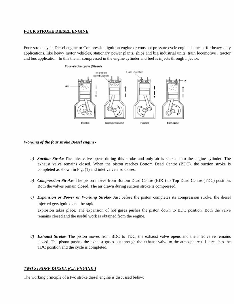
Four-stroke cycle Diesel engine or Compression ignition engine or constant pressure cycle engine is meant for heavy duty
applications, like heavy motor vehicles, stationary power plants, ships and big industrial units, train locomotive , tractor
and bus application. In this the air compressed in the engine cylinder and fuel is injects through injector.
Working of the four stroke Diesel engine-
a) Suction Stroke-The inlet valve opens during this stroke and only air is sucked into the engine cylinder. The
exhaust valve remains closed. When the piston reaches Bottom Dead Centre (BDC), the suction stroke is
completed as shown in Fig. (1) and inlet valve also closes.
b) Compression Stroke- The piston moves from Bottom Dead Centre (BDC) to Top Dead Centre (TDC) position.
Both the valves remain closed. The air drawn during suction stroke is compressed.
c) Expansion or Power or Working Stroke- Just before the piston completes its compression stroke, the diesel
injected gets ignited and the rapid
explosion takes place. The expansion of hot gases pushes the piston down to BDC position. Both the valve
remains closed and the useful work is obtained from the engine.
d) Exhaust Stroke- The piston moves from BDC to TDC, the exhaust valve opens and the inlet valve remains
closed. The piston pushes the exhaust gases out through the exhaust valve to the atmosphere till it reaches the
TDC position and the cycle is completed.
TWO STROKE DIESEL (C.I. ENGINE-)
The working principle of a two stroke diesel engine is discussed below:
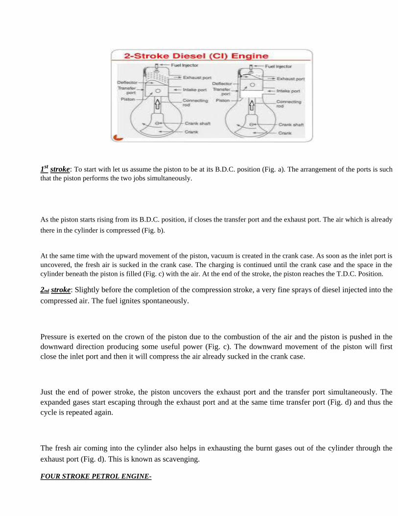
1st stroke: To start with let us assume the piston to be at its B.D.C. position (Fig. a). The arrangement of the ports is such
that the piston performs the two jobs simultaneously.
As the piston starts rising from its B.D.C. position, if closes the transfer port and the exhaust port. The air which is already
there in the cylinder is compressed (Fig. b).
At the same time with the upward movement of the piston, vacuum is created in the crank case. As soon as the inlet port is
uncovered, the fresh air is sucked in the crank case. The charging is continued until the crank case and the space in the
cylinder beneath the piston is filled (Fig. c) with the air. At the end of the stroke, the piston reaches the T.D.C. Position.
2nd stroke: Slightly before the completion of the compression stroke, a very fine sprays of diesel injected into the
compressed air. The fuel ignites spontaneously.
Pressure is exerted on the crown of the piston due to the combustion of the air and the piston is pushed in the
downward direction producing some useful power (Fig. c). The downward movement of the piston will first
close the inlet port and then it will compress the air already sucked in the crank case.
Just the end of power stroke, the piston uncovers the exhaust port and the transfer port simultaneously. The
expanded gases start escaping through the exhaust port and at the same time transfer port (Fig. d) and thus the
cycle is repeated again.
The fresh air coming into the cylinder also helps in exhausting the burnt gases out of the cylinder through the
exhaust port (Fig. d). This is known as scavenging.
FOUR STROKE PETROL ENGINE-
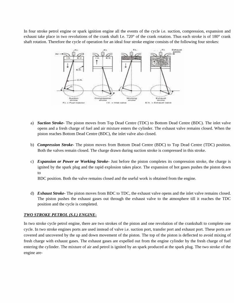
In four stroke petrol engine or spark ignition engine all the events of the cycle i.e. suction, compression, expansion and
exhaust take place in two revolutions of the crank shaft I.e. 720° of the crank rotation. Thus each stroke is of 180° crank
shaft rotation. Therefore the cycle of operation for an ideal four stroke engine consists of the following four strokes:
a) Suction Stroke- The piston moves from Top Dead Centre (TDC) to Bottom Dead Centre (BDC). The inlet valve
opens and a fresh charge of fuel and air mixture enters the cylinder. The exhaust valve remains closed. When the
piston reaches Bottom Dead Centre (BDC), the inlet valve also closed.
b) Compression Stroke- The piston moves from Bottom Dead Centre (BDC) to Top Dead Centre (TDC) position.
Both the valves remain closed. The charge drawn during suction stroke is compressed in this stroke.
c) Expansion or Power or Working Stroke- Just before the piston completes its compression stroke, the charge is
ignited by the spark plug and the rapid explosion takes place. The expansion of hot gases pushes the piston down
to
BDC position. Both the valve remains closed and the useful work is obtained from the engine.
d) Exhaust Stroke- The piston moves from BDC to TDC, the exhaust valve opens and the inlet valve remains closed.
The piston pushes the exhaust gases out through the exhaust valve to the atmosphere till it reaches the TDC
position and the cycle is completed.
TWO STROKE PETROL (S.I.) ENGINE-
In two stroke cycle petrol engine, there are two strokes of the piston and one revolution of the crankshaft to complete one
cycle. In two stroke engines ports are used instead of valve i.e. suction port, transfer port and exhaust port. These ports are
covered and uncovered by the up and down movement of the piston. The top of the piston is deflected to avoid mixing of
fresh charge with exhaust gases. The exhaust gases are expelled out from the engine cylinder by the fresh charge of fuel
entering the cylinder. The mixture of air and petrol is ignited by an spark produced at the spark plug. The two stroke of the
engine are-

First Stroke - Assuming the piston to be at the BDC position. The inlet port is converted by the piston whereas the transfer
port and exhaust port are uncovered. The piston moves from BDC to TDC. The air petrol mixture enters the cylinder. On
the upward movement of the piston, first of all the transfer port is converted and then immediately, the exhaust port is
covered. Simultaneously the suction port also
gets uncovered, the upward movement of the piston helps to compress the air fuel mixture at the top and creates partial
vacuum at the bottom in the crankcase which gets filled with air fuel mixture by the atmospheric pressure. At the end of
the stroke, the piston reaches the TDC position completing the compression stroke as shown in Fig. (a) and (b).
Second Stroke- Just before the completion of the compression stroke, the compressed charge is ignited in the combustion
chamber, by means of an electric spark produced by the spark plug. Combustion of air fuel mixture pushes the piston in
the downward direction, on the power stroke producing useful work. The movement of the power action is over, the
exhaust port is uncovered. The exhaust gases escape to the atmosphere. Further movement of the piston covers the inlet
port and the fresh charge is compressed in the crankcase. Simultaneously the transfer port is also uncovered. The
compressed mixture of air fuel enters the combustion chamber. The deflected shape of the piston avoids inter-mixing of
the fresh charge and exhaust gases i.e. the fresh charge rises to the top of the cylinder and pushes out most of the exhaust
gases. Thus the three actions, power, exhaust and induction are completed from TDC to BDC position completing one
cycle i.e. two stroke of the piston and one revolution of the crankshaft as shown in .

EXPERIMENT NO-6
AIM:- Deflections of a truss-horizontal deflections & vertical deflections of various
joints of a pin-jointed truss.
Apparatus:
The model consists of a 4 panel of a Pratt truss, each panel being 40cm in horizontal direction and 30cm in
vertical direction. The truss is hanging and supported by joints A and E with firm supports. Load can be
applied on each panel point. All tension members are provided with detachable spring so as to obtain
appreciable deformation of the member. Direction of the diagonal members may be changed.
Apparatus can be used to illustrate visually the nature of forces set up in various members of the truss.
Theory:
The deflection of a node of truss under a given load is given by:
Where,
F = force in any member under the given system of loading
U = force in any member under a unit load which acts in the direction of deflection. L = length of any
member
A = area of cross section of any member E =
modulus of elasticity of the member

Here, L/AE is a property of a member, which is equal to the extension per unit load. It may be determined
for each member separately by suspending a load from it and noting the extension.
Procedure:
1. Each member with a spring is isolated and its stiffness is determined by
suspending a load from it and noting the extension.
2. The truss is loaded with 0.25 Kg load at each node and this is assumed to be the initial
position.
3. Now additional loads are applied at the nodes where the deflection is required. The
deflection is observed.
4. The deflection for the required node is calculated from the eq. (1).

Precautions:
i) Apply the loads without any jerk.
ii) Perform the experiment at a location, which is away from any external
disturbance.
iii) Ensure that the supports are rigid.
iv) The load applied should be within the allowed limits for the apparatus.
Result:
The deflections at various nodes are: Σ∆ for
node N1 =
Σ∆ for node N2 = Σ∆
for node N3 =
EXPERIMENT NO-7
AIM:- Elastic displacements (vertical & horizontal) of curved members.
Apparatus:
The apparatus consists of a steel bar which is used as different curved members viz. circle, semi circle with
straight arm, quadrant of a circle and quadrant of a circle with straight arm. The bottom ends of the members
are fixed to the base to impart rigidity to the structures. Under the application of a load at free end its
horizontal and vertical deflection is measured with the help of a dial gauge.
Theory:
The theorem used to find elastic displacement is the Castigliano’s First Theorem which states that
‘Partial derivative of the total strain in energy of a structure with respect to any force gives the
displacement of the point of its application in the direction of the force.
The total strain energy of the structure is determined in terms of all other loads with their actual values and
a fictitious load at the point at which the
deflection is required acting in the direction of the deflection. After particle differentiation with respect
to P, the actual value (if P is an actual load) of zero is substituted for P. The result is the deflection
required.
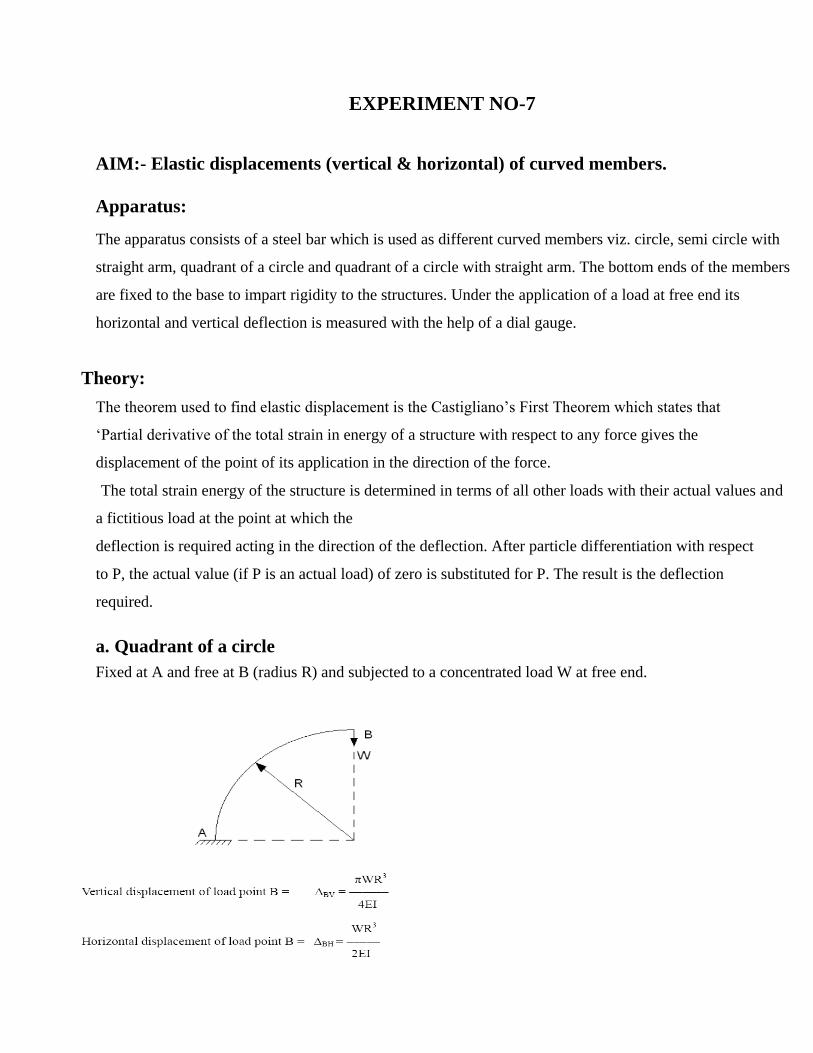
a. Quadrant of a circle
Fixed at A and free at B (radius R) and subjected to a concentrated load W at free end.

b. Quadrant with a straight leg
From A to B, quadrant of a circle of radius R, from B to C straight length of
c. Semi circle with straight arm
From A to C semi circle of radius R, A to B straight length of y
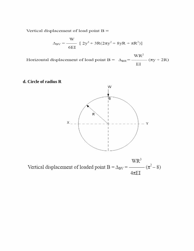
d. Circle of radius R
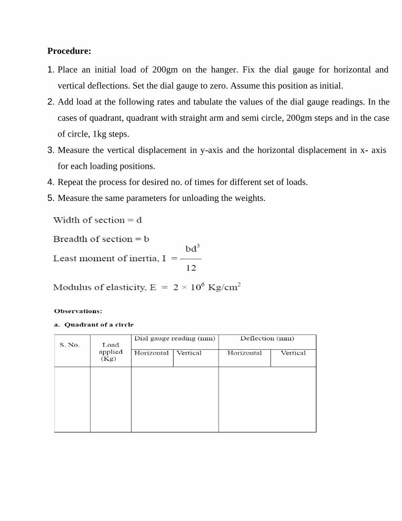
Procedure:
1. Place an initial load of 200gm on the hanger. Fix the dial gauge for horizontal and
vertical deflections. Set the dial gauge to zero. Assume this position as initial.
2. Add load at the following rates and tabulate the values of the dial gauge readings. In the
cases of quadrant, quadrant with straight arm and semi circle, 200gm steps and in the case
of circle, 1kg steps.
3. Measure the vertical displacement in y-axis and the horizontal displacement in x- axis
for each loading positions.
4. Repeat the process for desired no. of times for different set of loads.
5. Measure the same parameters for unloading the weights.

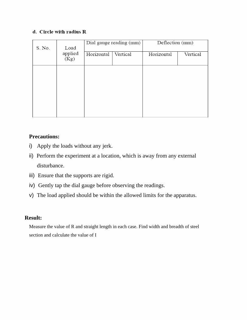
Precautions:
i) Apply the loads without any jerk.
ii) Perform the experiment at a location, which is away from any external
disturbance.
iii) Ensure that the supports are rigid.
iv) Gently tap the dial gauge before observing the readings.
v) The load applied should be within the allowed limits for the apparatus.
Result:
Measure the value of R and straight length in each case. Find width and breadth of steel
section and calculate the value of I
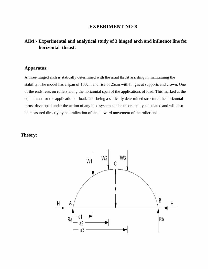
EXPERIMENT NO-8
AIM:- Experimental and analytical study of 3 hinged arch and influence line for
horizontal thrust.
Apparatus:
A three hinged arch is statically determined with the axial thrust assisting in maintaining the
stability. The model has a span of 100cm and rise of 25cm with hinges at supports and crown. One
of the ends rests on rollers along the horizontal span of the applications of load. This marked at the
equidistant for the application of load. This being a statically determined structure, the horizontal
thrust developed under the action of any load system can be theoretically calculated and will also
be measured directly by neutralization of the outward movement of the roller end.
Theory:

Procedure:
1. Balance the self weight of the arch by putting load on the thrust hanger till the appropriate
equilibrium conditions are obtained. The moveable end of the arch is positioned such that
it shows a tendency to move inside on tapping the supporting table.
2. Place a few loads on the arch in any chosen positions. Balance these by placing
additional weights on the hanger for horizontal thrust. The additional weights on the
thrust hanger give the experimental value of the horizontal thrust.
3. Measure the distances a1, a2 and a3 from A with respect to the loads applied, W1, W2 and
W3.
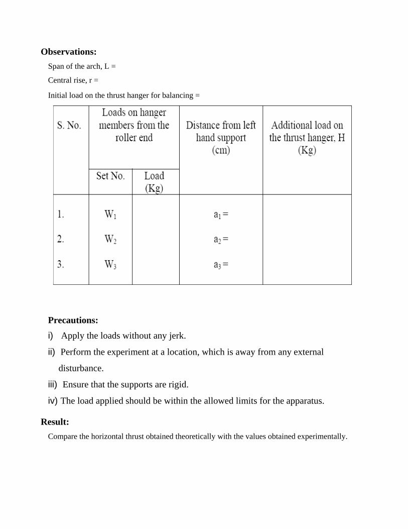
Observations:
Span of the arch, L =
Central rise, r =
Initial load on the thrust hanger for balancing =
Precautions:
i) Apply the loads without any jerk.
ii) Perform the experiment at a location, which is away from any external
disturbance.
iii) Ensure that the supports are rigid.
iv) The load applied should be within the allowed limits for the apparatus.
Result:
Compare the horizontal thrust obtained theoretically with the values obtained experimentally.

EXPERIMENT NO-9
AIM:- Experimental and analytical study of behavior of struts with various end
conditions.
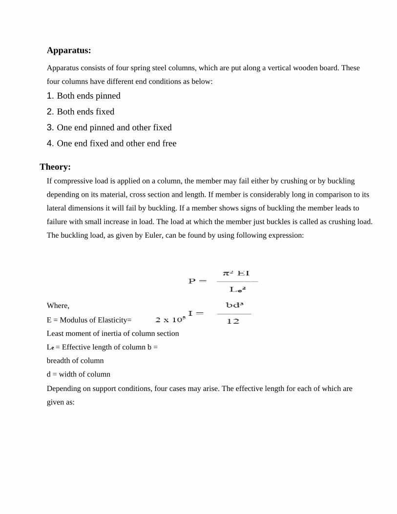
Apparatus:
Apparatus consists of four spring steel columns, which are put along a vertical wooden board. These
four columns have different end conditions as below:
1. Both ends pinned
2. Both ends fixed
3. One end pinned and other fixed
4. One end fixed and other end free
Theory:
If compressive load is applied on a column, the member may fail either by crushing or by buckling
depending on its material, cross section and length. If member is considerably long in comparison to its
lateral dimensions it will fail by buckling. If a member shows signs of buckling the member leads to
failure with small increase in load. The load at which the member just buckles is called as crushing load.
The buckling load, as given by Euler, can be found by using following expression:
Where,
E = Modulus of Elasticity= N/mm² for steel I =
Least moment of inertia of column section
Le = Effective length of column b =
breadth of column
d = width of column
Depending on support conditions, four cases may arise. The effective length for each of which are
given as:

1. Both ends are fixed, Le = L/ 2
2. One end is fixed and other is pinned, Le = L/√ 2
3. Both ends are pinned, Le = L
4. One end is fixed and other is free, Le = 2L
Where,
L = Length of the column
Procedure:
1. Pin a graph paper on the wooden board behind the column.
2. Apply the load at the top of columns.
3. Note the buckling patterns for each of the four columns.
4. Trace the deflected shapes of the columns over the graph paper. Mark the points
of change of curvature of the curves and measure the effective or equivalent
length for each case separately.
5. Calculate the theoretical effective lengths and thus buckling loads by the
expressions given above and compare them with the observed values

Result:
1. Calculate the buckling load for each case
Study the shape of the curve and the points of buckling traced at th

EXPERIMENT NO-10
AIM:- To determine elastic properties of a beam.
Apparatus:
The apparatus consists of a flexible beam supported by two rigid supports equally distant from the ends of
the beam. This set up provides two over hangs at the ends of the beam. The beam has notches separated by
0.1 meter distance. Two hangers are provided at the free ends of the beam to suspend the loads at the ends.
Theory
Where,
a = length of overhang on each side W = load
applied at the free ends
L = main span
E = modulus of elasticity of the material of the beam I = moment
of inertia of cross section of the beam

Where, b = width of the beam d =
depth of the beam
Procedure:
1. Find b and d of the beam with the help of a vernier calipers
2. Calculate the theoretical value of (EI) from equation (3) and the above
parameters.
3. Measure the main span and overhang span of the beam with a scale
4. By applying equal loads at the free ends of the overhang beam, find the central
deflection y. Repeat the process for different values of loads.
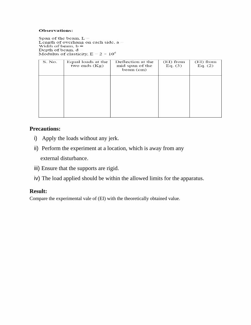
Precautions:
i) Apply the loads without any jerk.
ii) Perform the experiment at a location, which is away from any
external disturbance.
iii) Ensure that the supports are rigid.
iv) The load applied should be within the allowed limits for the apparatus.
Result:
Compare the experimental vale of (EI) with the theoretically obtained value.