basics of peripheral nerve stimulation
TRANSCRIPT
Presentor : Dr.Yamini V S
Moderator : Dr. J.BalaVenkat
GANGA HOSPITAL,COIMBATORE
BASICS OF PERIPHERAL NERVE STIMULATION
INTRODUCTION
• Electrical nerve stimulation is one of the most common techniques of nerve location
• Depolarisation of nerve membrane results in:
Objective - Contraction of effector muscles ( motor fibers )
Subjective - Paraesthesia ( Sensory fibers )
HISTORY
• 1780 : GALVANI described the effect of Neuromuscular stimulation
• 1912 : PERTHES developed and described Electrical nerve stimulator
• 1955 : PEARSON – concept of Insulated needles for nerve location
• 1962 : GREENBLATT & DENSON – Portable variable current output nerve stimulator
• 1984 : FORD – Lack of accuracy with noninsulated needles , Suggested the use of Constant current nerve stimulator
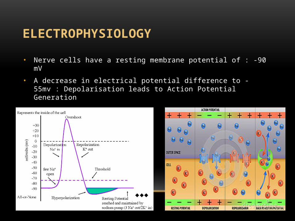
ELECTROPHYSIOLOGY
• Nerve cells have a resting membrane potential of : -90 mV
• A decrease in electrical potential difference to -55mv : Depolarisation leads to Action Potential Generation
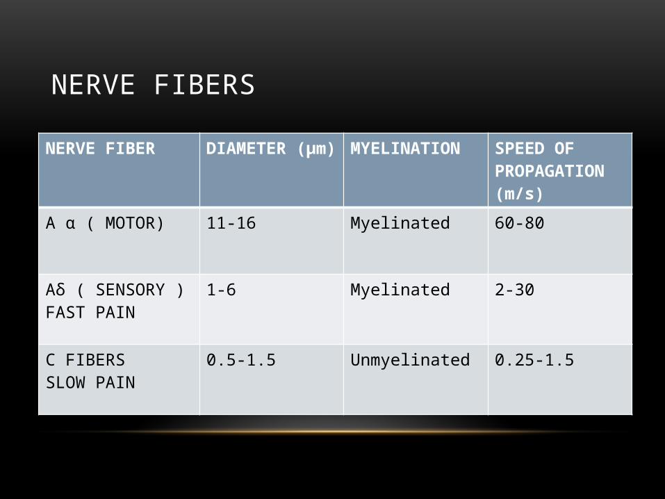
NERVE FIBERS
NERVE FIBER DIAMETER (µm) MYELINATION SPEED OF PROPAGATION(m/s)
A α ( MOTOR) 11-16 Myelinated 60-80
Aδ ( SENSORY )FAST PAIN
1-6 Myelinated 2-30
C FIBERS SLOW PAIN
0.5-1.5 Unmyelinated 0.25-1.5
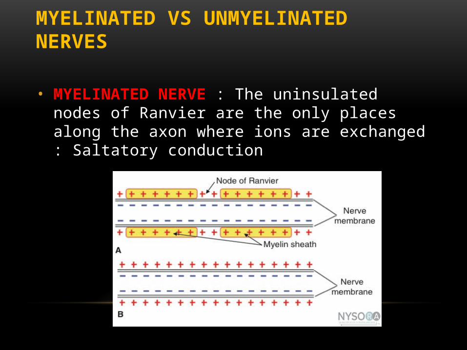
MYELINATED VS UNMYELINATED NERVES
• MYELINATED NERVE : The uninsulated nodes of Ranvier are the only places along the axon where ions are exchanged : Saltatory conduction
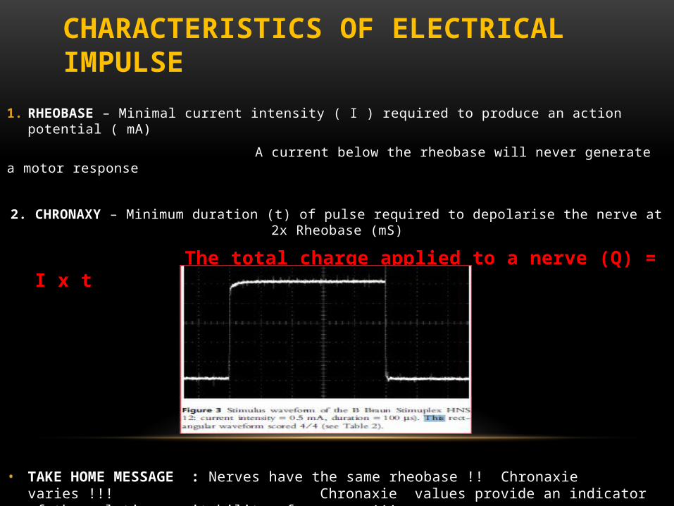
CHARACTERISTICS OF ELECTRICAL IMPULSE
1. RHEOBASE – Minimal current intensity ( I ) required to produce an action potential ( mA)
A current below the rheobase will never generate a motor response
2. CHRONAXY – Minimum duration (t) of pulse required to depolarise the nerve at 2x Rheobase (mS)
The total charge applied to a nerve (Q) = I x t
• TAKE HOME MESSAGE : Nerves have the same rheobase !! Chronaxie varies !!! Chronaxie values provide an indicator of the relative excitability of a nerve !!!
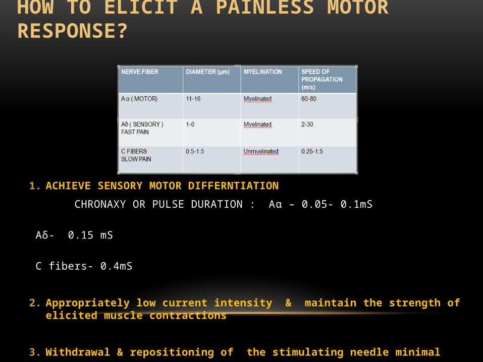
HOW TO ELICIT A PAINLESS MOTOR RESPONSE?
1. ACHIEVE SENSORY MOTOR DIFFERNTIATION
CHRONAXY OR PULSE DURATION : Aα – 0.05- 0.1mS
Aδ- 0.15 mS
C fibers- 0.4mS
2. Appropriately low current intensity & maintain the strength of elicited muscle contractions
3. Withdrawal & repositioning of the stimulating needle minimal
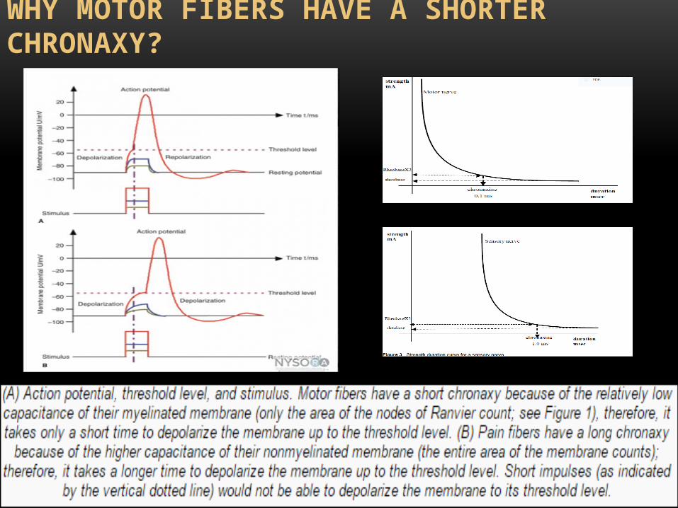
WHY MOTOR FIBERS HAVE A SHORTER CHRONAXY?
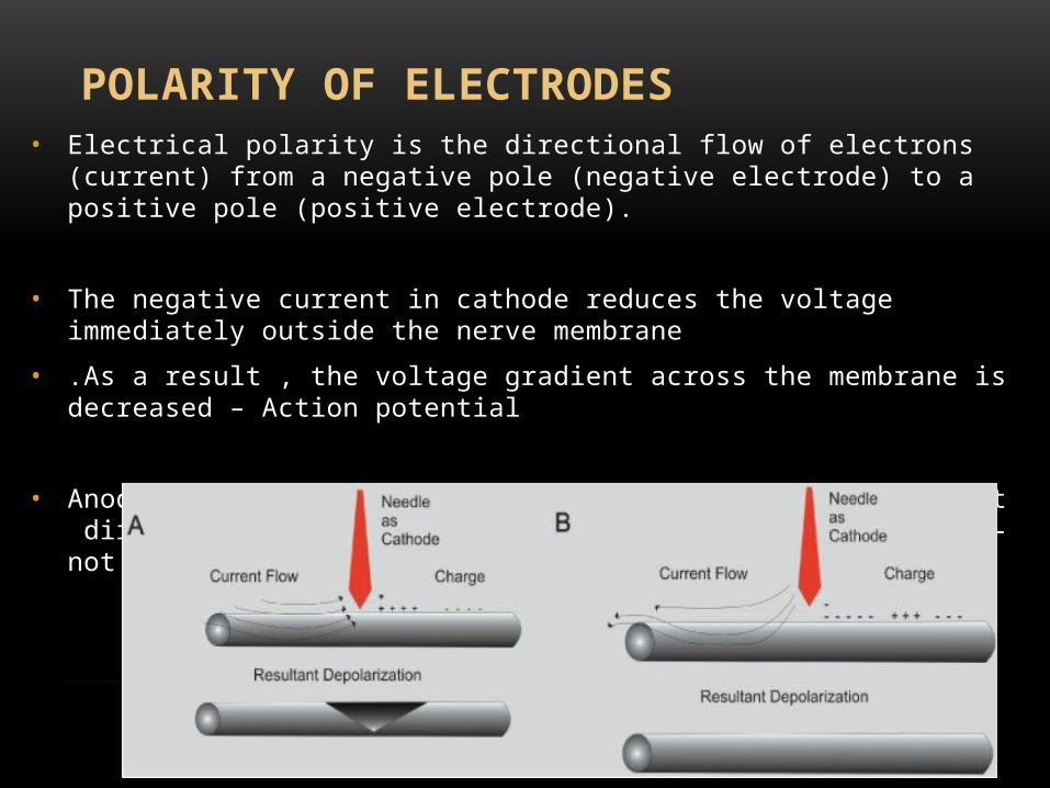
POLARITY OF ELECTRODES• Electrical polarity is the directional flow of electrons (current) from a negative pole (negative
electrode) to a positive pole (positive electrode).
• The negative current in cathode reduces the voltage immediately outside the nerve membrane
• .As a result , the voltage gradient across the membrane is decreased – Action potential
• Anode site – 20 cm away from stimulation site – to prevent direct stimulation of muscles via local flow of current – not critical with constant current output generator
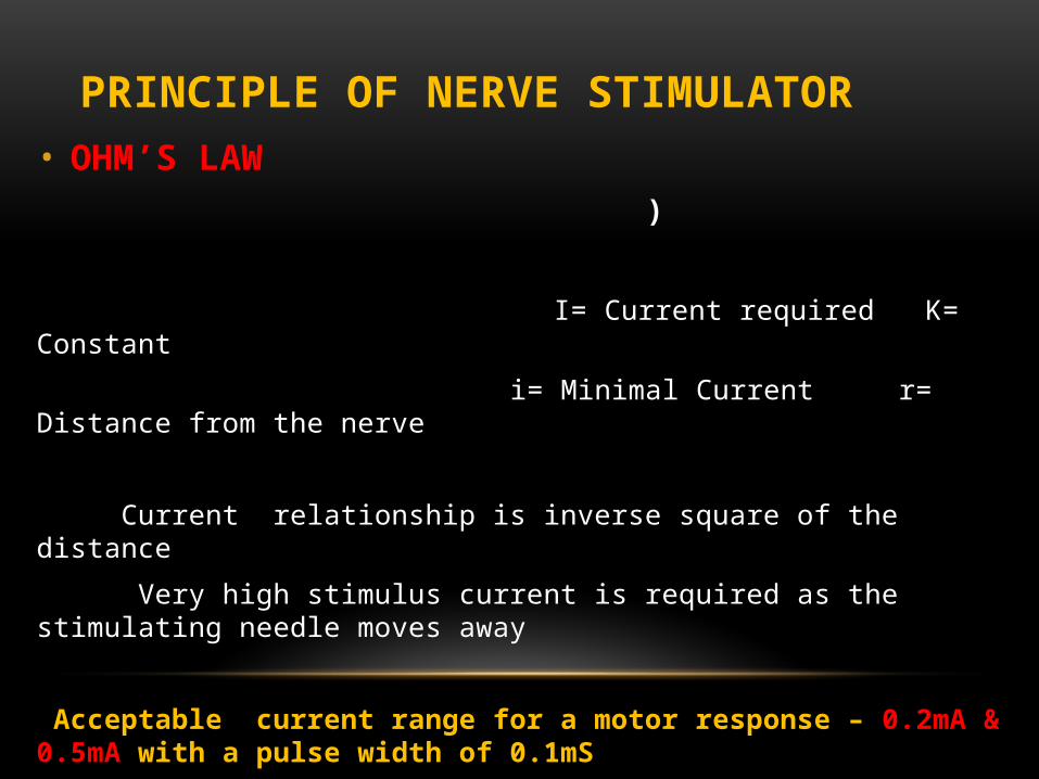
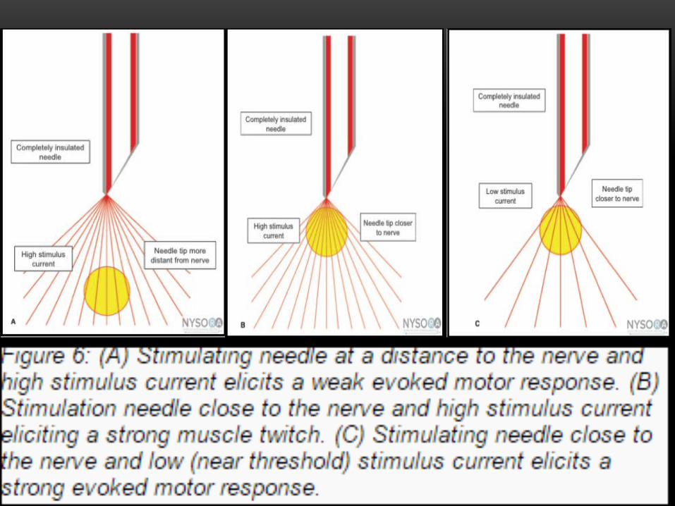
PRINCIPLE OF NERVE STIMULATOR• OHM’S LAW )
I= Current required K= Constant
i= Minimal Current r= Distance from the nerve
Current relationship is inverse square of the distance
Very high stimulus current is required as the stimulating needle moves away
Acceptable current range for a motor response – 0.2mA & 0.5mA with a pulse width of 0.1mS
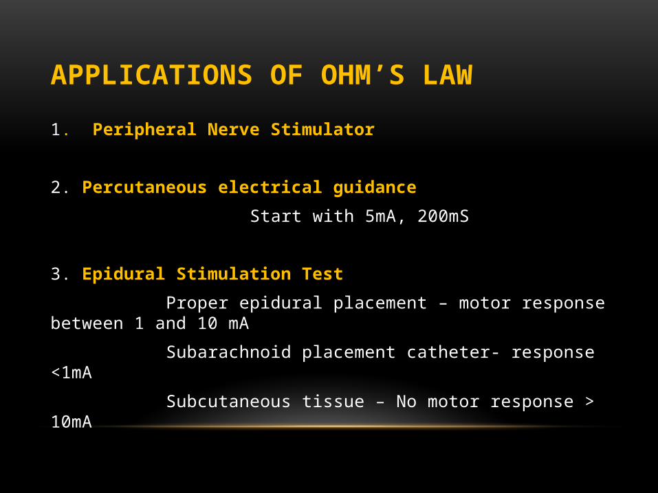
APPLICATIONS OF OHM’S LAW
1. Peripheral Nerve Stimulator
2. Percutaneous electrical guidance
Start with 5mA, 200mS
3. Epidural Stimulation Test
Proper epidural placement – motor response between 1 and 10 mA
Subarachnoid placement catheter- response <1mA
Subcutaneous tissue – No motor response > 10mA
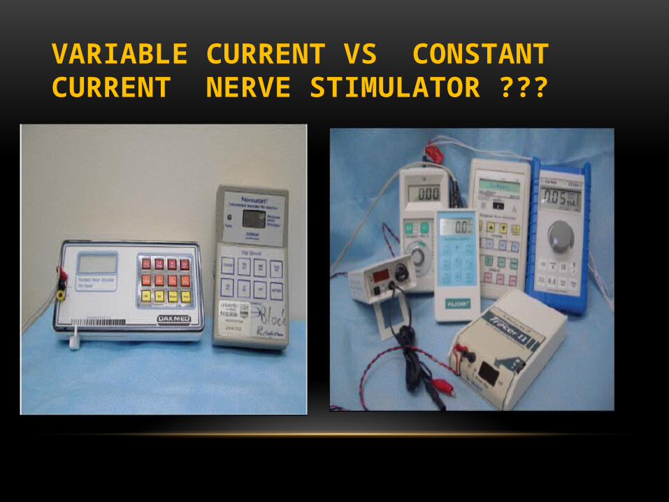
VARIABLE CURRENT VS CONSTANT CURRENT NERVE STIMULATOR ???
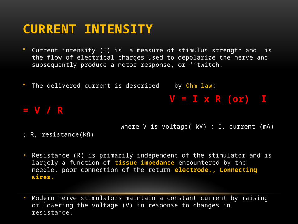
CURRENT INTENSITY Current intensity (I) is a measure of stimulus strength and is the flow of electrical
charges used to depolarize the nerve and subsequently produce a motor response, or ‘‘twitch.
The delivered current is described by Ohm law:
V = I x R (or) I = V / R where V is voltage( kV) ; I, current (mA) ; R, resistance(kΏ)
• Resistance (R) is primarily independent of the stimulator and is largely a function of tissue impedance encountered by the needle, poor connection of the return electrode., Connecting wires.
• Modern nerve stimulators maintain a constant current by raising or lowering the voltage (V) in response to changes in resistance.
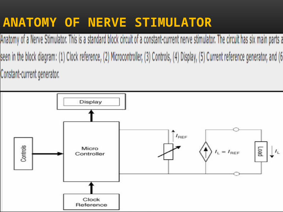
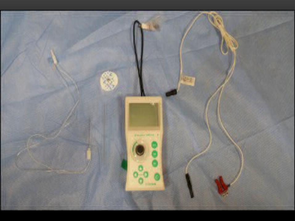
ANATOMY OF NERVE STIMULATOR
IMPORTANT FEATURES IN NERVE STIMULATOR
1. Constant Current Output
2. Accurate Current Display
3. Convenient means of current intensity control
4. Pulse width
5. Stimulating frequency
6. Disconnection and Malfunction indicator

VIDEO
NEW AND EMERGING CONCEPTS IN PERIPHERAL NERVE STIMULATION
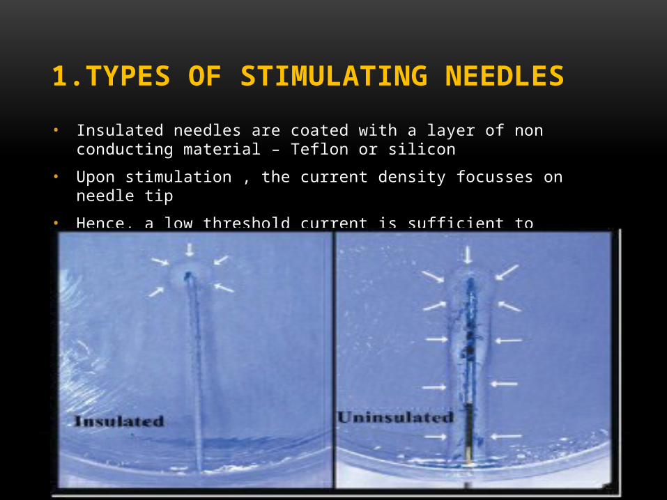
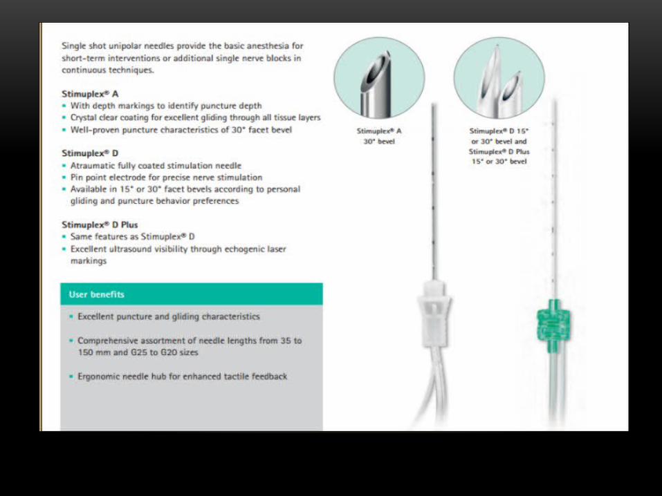
1.TYPES OF STIMULATING NEEDLES
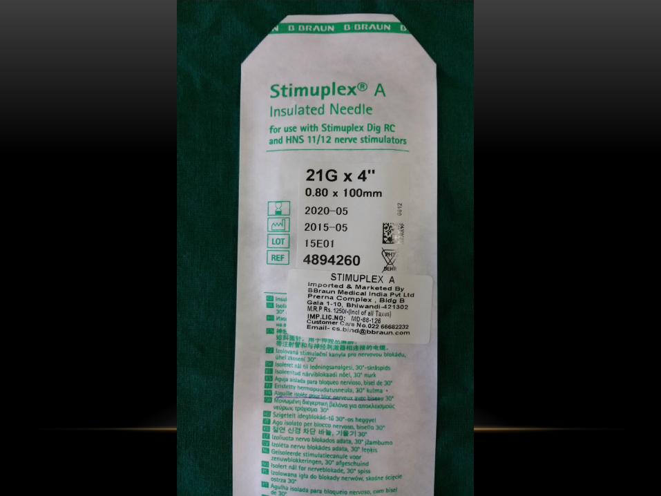
• Insulated needles are coated with a layer of non conducting material – Teflon or silicon
• Upon stimulation , the current density focusses on needle tip
• Hence, a low threshold current is sufficient to stimulate the target nerve
CURRENT DENSITY
• Current density describes the distribution of current flow in terms of current per cross-sectional area.
• A greater conductive area leads to decreased current density, and hence, a greater threshold current is needed to evoke an action potential at the same distance.
• The smaller the conductive area for the current flow at the needle tip, the higher the current density
• RAJ TEST : The loss of a motor response after the initial injection of local anesthetic (0.5 to 1.5 mL)
• Loss of response is actually due to increased conductive area and hence decreased current density surrounding the needle,caused by the spread of local anesthetic.
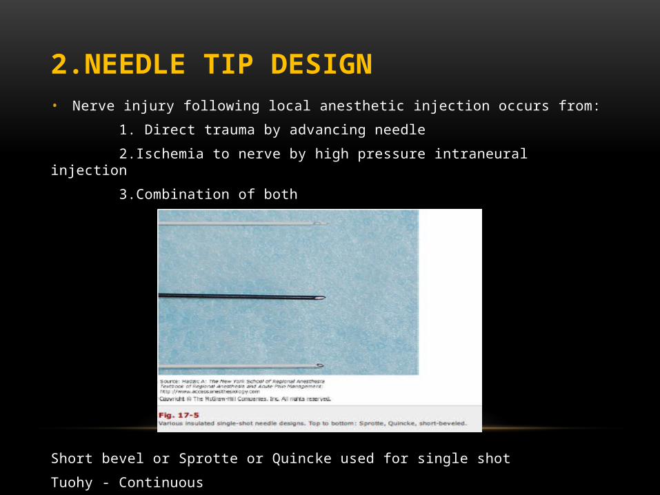
2.NEEDLE TIP DESIGN• Nerve injury following local anesthetic injection occurs from:
1. Direct trauma by advancing needle
2.Ischemia to nerve by high pressure intraneural injection
3.Combination of both
Short bevel or Sprotte or Quincke used for single shot
Tuohy - Continuous
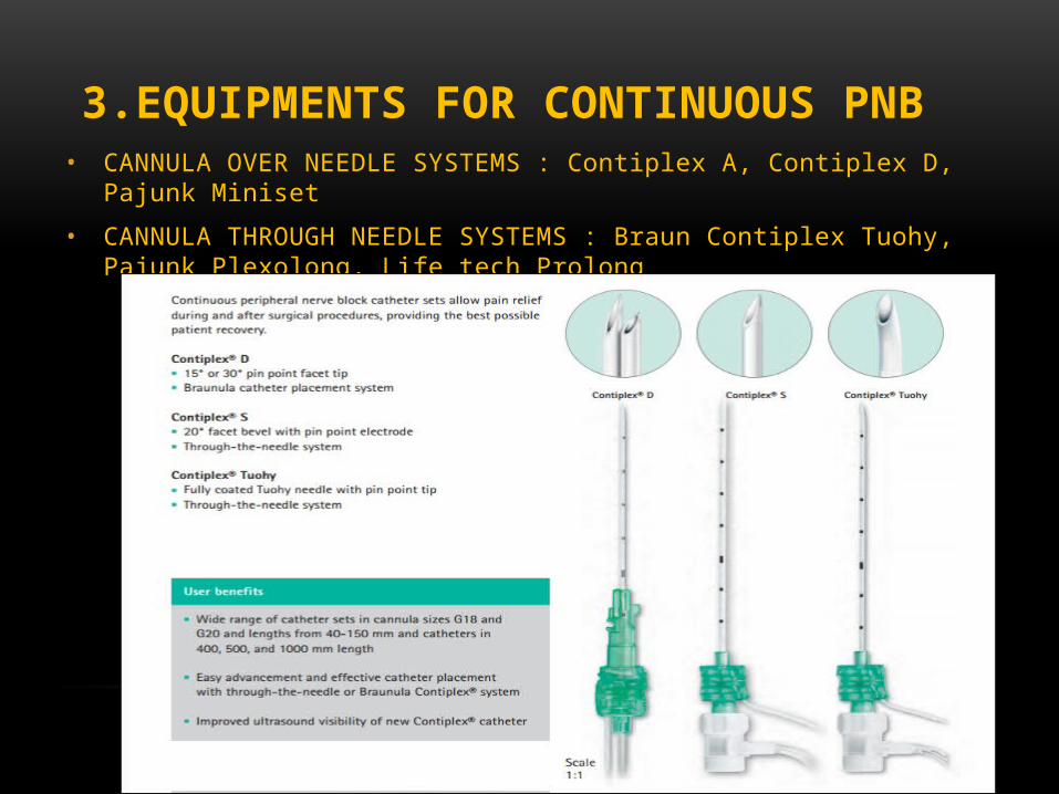
3.EQUIPMENTS FOR CONTINUOUS PNB• CANNULA OVER NEEDLE SYSTEMS : Contiplex A, Contiplex D, Pajunk Miniset
• CANNULA THROUGH NEEDLE SYSTEMS : Braun Contiplex Tuohy, Pajunk Plexolong, Life tech Prolong
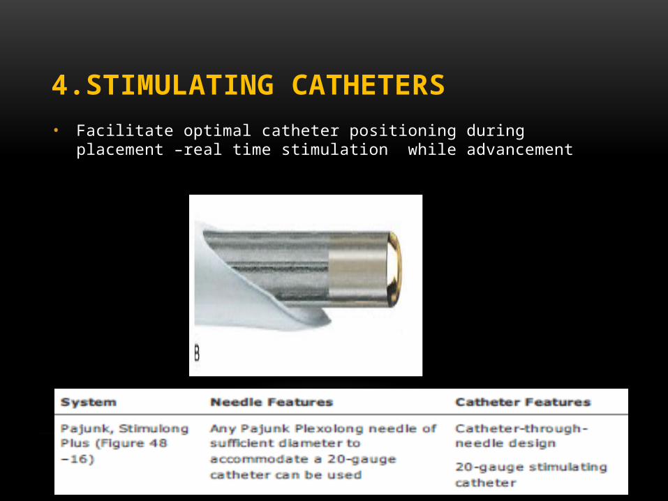
4.STIMULATING CATHETERS• Facilitate optimal catheter positioning during placement –real time stimulation while
advancement
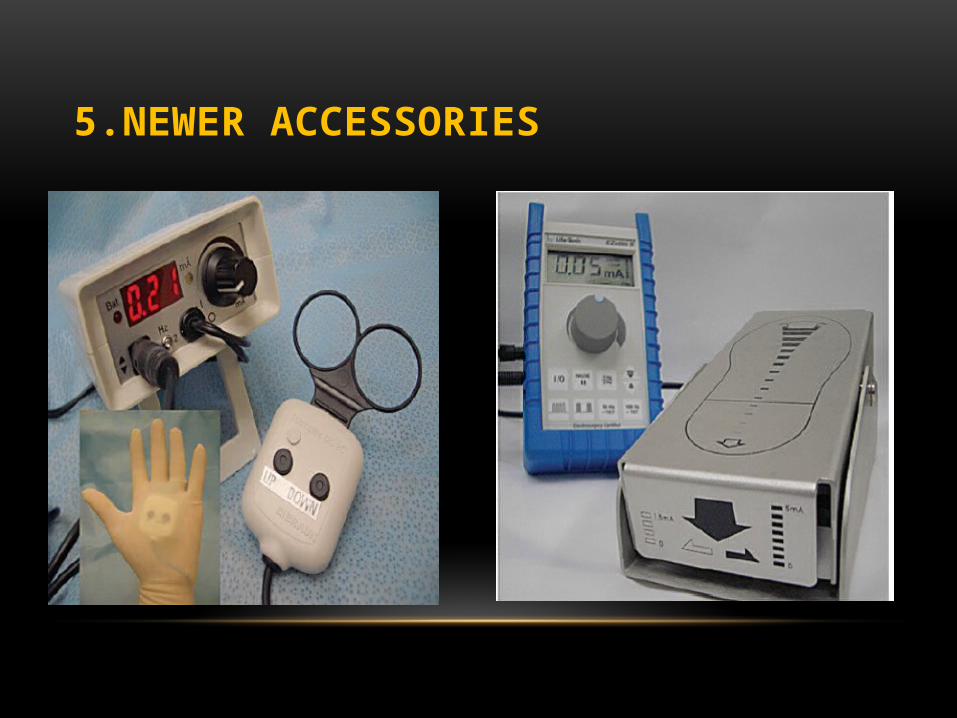
5.NEWER ACCESSORIES
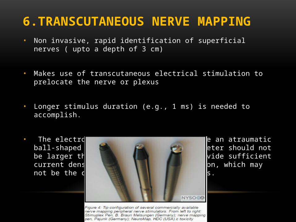
6.TRANSCUTANEOUS NERVE MAPPING• Non invasive, rapid identification of superficial nerves ( upto a depth of 3 cm)
• Makes use of transcutaneous electrical stimulation to prelocate the nerve or plexus
• Longer stimulus duration (e.g., 1 ms) is needed to accomplish.
• The electrode tip of the pen should have an atraumatic ball-shaped tip. The conductive tip diameter should not be larger than approximately 3 mm to provide sufficient current density and spatial discrimination, which may not be the case with larger tip diameters.
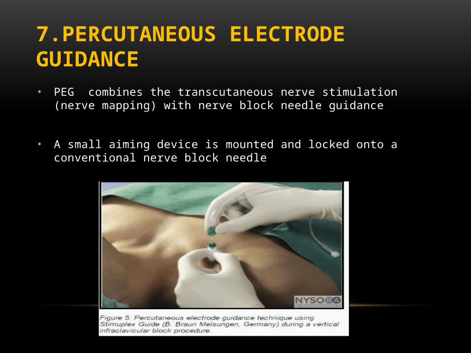
• PEG combines the transcutaneous nerve stimulation (nerve mapping) with nerve block needle guidance
• A small aiming device is mounted and locked onto a conventional nerve block needle
7.PERCUTANEOUS ELECTRODE GUIDANCE
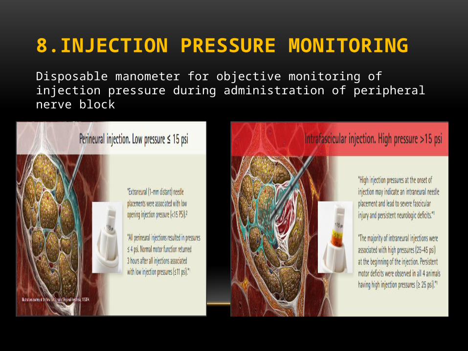
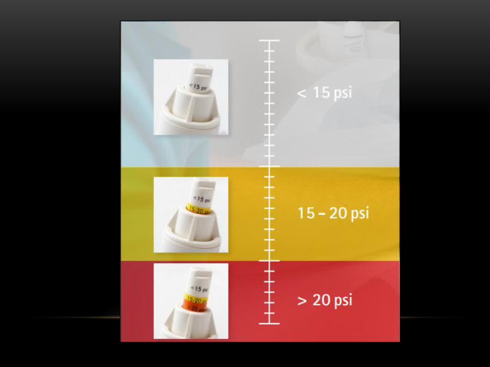
8.INJECTION PRESSURE MONITORINGDisposable manometer for objective monitoring of injection pressure during administration of peripheral nerve block
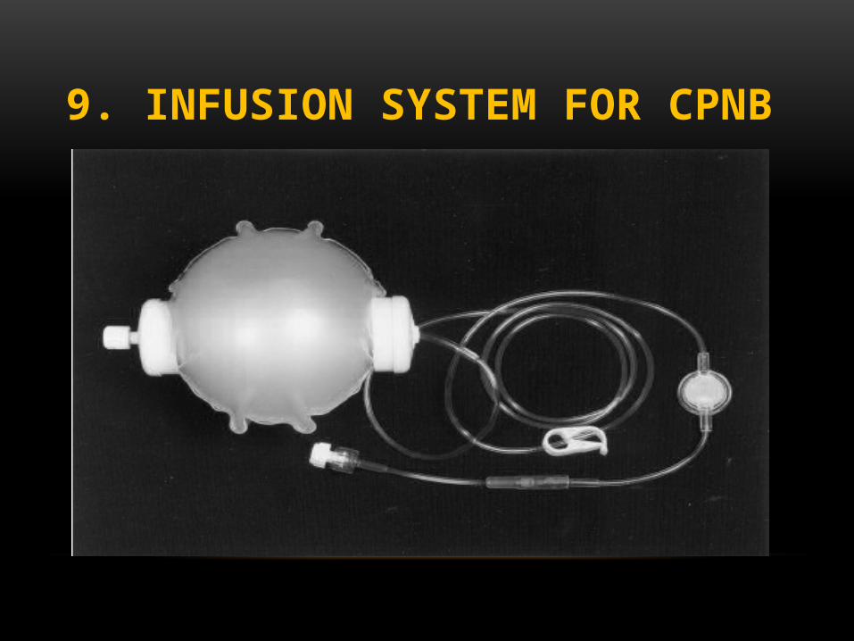
9. INFUSION SYSTEM FOR CPNB
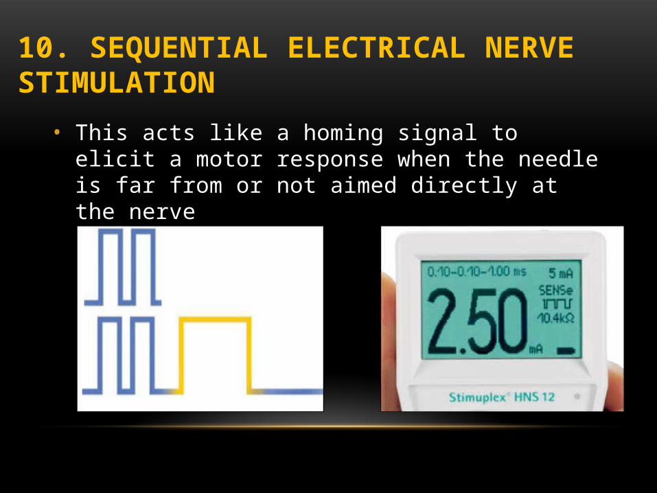
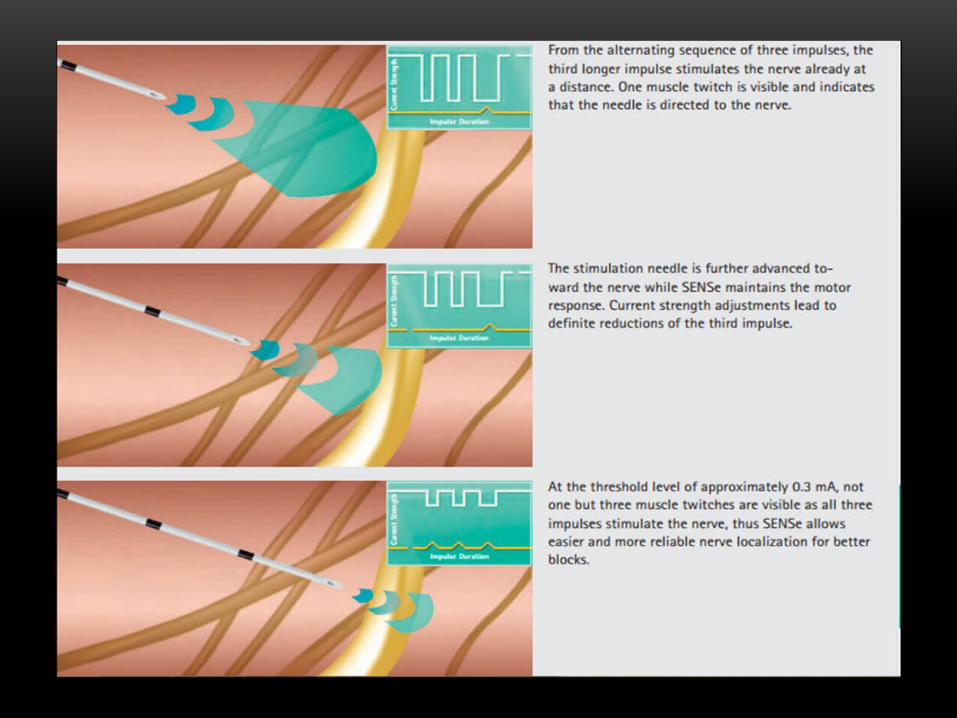
10. SEQUENTIAL ELECTRICAL NERVE STIMULATION• This acts like a homing signal to elicit a motor response when
the needle is far from or not aimed directly at the nerve
PERIPHERAL NERVE STIMULATION IS NO SUBSTITUTE FOR ANATOMICAL KNOWLEDGE

THANK YOU