batteries supporting information
TRANSCRIPT

Supporting Information
In-situ extracted poly(acrylic acid) contributing to electrospun nanofiber
separators with precisely tuned pore structures for ultra-stable lithium-sulfur
batteries
Xiaobo Zhu, Yue Ouyang, Jiawei Chen, Xinguo Zhu, Xiang Luo, Feili Lai, Hui Zhang,
Yue-E Miao*, Tianxi Liu
Electronic Supplementary Material (ESI) for Journal of Materials Chemistry A.This journal is © The Royal Society of Chemistry 2019

Fig. S1 Microscope photographs of different electrospinning precursor solutions: (a)
PAN, (b) PAA and (c) PAN6/PAA4.

Fig. S2 SEM images and the corresponding pore size distributions (inset) of different
membranes: (a) PAN, (b) PAN8/PAA2, (c) PAN4/PAA6, (d) E-PAN, (e) E-PAN8/PAA2,
(f) E-PAN4/PAA6.

Fig. S3 (a) The pore size distribution, and (b) electrolyte contact angle of Celgard.

Fig. S4 FTIR spectra of different membranes.

Fig. S5 (a) Representative stress - strain curves for various membranes. Tensile fracture
photos of (b) PAN6/PAA4 and (c) E-PAN6/PAA4 separators.

Fig. S6 CV curves of (a, b) Celgard and (c, d) PAN6/PAA4 separators obtained at a
scanning rate of 0.1 mV s−1 and different scanning rates.

Fig. S7 Linear fits of the peak currents of Li-S batteries with (a) Celgard and (b)
PAN6/PAA4 separators.

Fig. S8 Electrochemical performance of the batteries assembled by E-PAN6/PAA4 at a
low electrolyte addition (the ratio of electrolyte/sulfur is about 15 μL mg-1). (a) First
cycle discharge/charge curves and (b) rate performance at 0.1, 0.2, 0.5, 1, 2 and 3 C.

Fig. S9 The cycling performance of batteries with E-PAN6/PAA4 and Celgard
separators at a low rate of 0.2 C.

Fig. S10 SEM images with the corresponding digital photographs (inset) of (a) the
cathode side and (b) anode side of E-PAN6/PAA4 separator after 500 cycles of
discharge/charge tests.

Fig. S11 SEM images of the Li anodes retrieved from Li-S batteries assembled with (a)
E-PAN6/PAA4 and (b) Celgard separators after the cycling test.

Table S1. Physical properties of different membranes.
SamplesThickness
(μm)
Porosity
(%)
Density
(g cm-3)
Contact angle
(°)
Celgard 26 40.1 0.57 37.2
PAN 30 91.2 0.16 0
PAN8/PAA2 32 90.5 0.17 0
PAN6/PAA4 33 87.3 0.15 0
PAN4/PAA6 34 83.1 0.16 0
E-
PAN8/PAA2
28 37.1 0.17 0
E-
PAN6/PAA4
30 29.4 0.17 0
E-
PAN4/PAA6
29 19.6 0.19 0
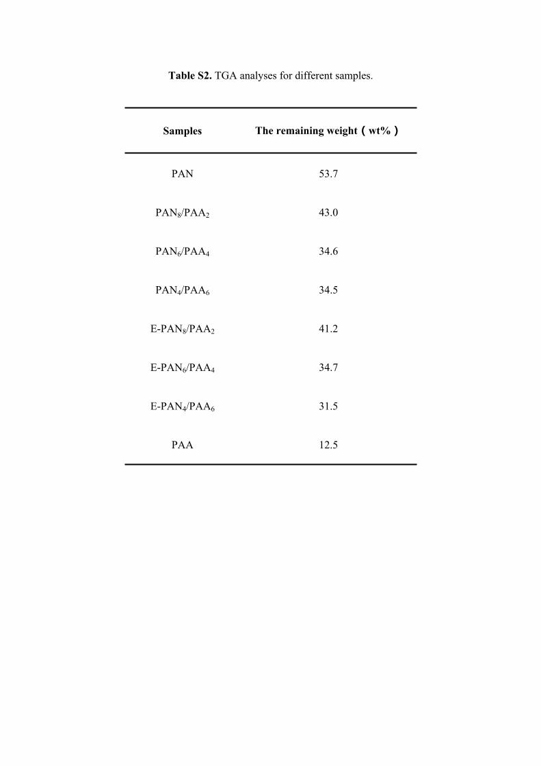
Table S2. TGA analyses for different samples.
Samples The remaining weight(wt%)
PAN 53.7
PAN8/PAA2 43.0
PAN6/PAA4 34.6
PAN4/PAA6 34.5
E-PAN8/PAA2 41.2
E-PAN6/PAA4 34.7
E-PAN4/PAA6 31.5
PAA 12.5

Table S3. Summary of the mechanical properties of different membranes.
SamplesTensile strength
(MPa)
Elongation
at break (%)
Young's modulus
(MPa)
PAN 1.61 ± 0.27 40.17 ± 4.12 4 ± 1
PAN8/PAA2 10.88 ± 1.96 53.40 ± 4.31 167 ± 21
PAN6/PAA4 15.82 ± 1.31 82.22 ± 2.14 485 ± 26
PAN4/PAA6 23.75 ± 2.19 105.23 ± 2.51 541 ± 43
E-PAN8/PAA2 22.41 ± 3.07 28.24 ± 1.78 396 ± 34
E-PAN6/PAA4 27.17 ± 3.36 47.33 ± 1.59 637 ± 63
E-PAN4/PAA6 13.28 ± 1.34 34.50 ± 1.34 95 ± 32
Celgard-1 14.09 ± 2.16 78.64 ± 4.87 485 ± 47
Celgard-2 84.34 ± 4.12 18.44 ± 1.86 642 ± 69

Table S4. Fitted values for the equivalent circuit elements of the electrochemical
impedance spectroscopy.
Parameters R0 (Ω) Rct (Ω) Rsf (Ω)
PAN 3.5 3.9 ~
PAN8/PAA2 4.9 7.2 2.7
PAN6/PAA4 6.5 8.4 13.2
PAN4/PAA6 5.0 11.4 9.7
E-PAN8/PAA2 14.4 23.8 13.6
E-PAN6/PAA4 15.6 32.7 15.7
E-PAN4/PAA6 33.1 44.2 19.3
Celgard 8.7 12.4 14.4

Table S5. Summary of the Li+ diffusion coefficient ( ) for Celgard, PAN6/PAA4 LiD
and E-PAN6/PAA4 separators.
Parameters Celgard PAN6/PAA4 E-PAN6/PAA4
at peak R1 (cm2 s−1)Li
D 6.62×10⁻¹⁵ 2.28×10⁻¹⁴ 8.65×10⁻¹⁵
at peak R2 (cm2 s−1)Li
D 4.87×10⁻¹⁵ 2.65×10⁻¹⁴ 4.87×10⁻¹⁵
at peak O1 (cm2 s−1)Li
D 3.04×10⁻¹⁴ 1.30×10⁻¹³ 3.46×10⁻¹⁴

Table S6. Comparison of the electrochemical performance of this work with previous
works involving different separators using carbon-sulfur cathodes in Li-S batteries.
SeparatorSulfur
(%)
Initial
capacity
(mA h g-1)
Rate
capability
(mA h g-1)
Fading rate
per cycle
(%)
Refs
MoS2/Celgard 651471
(0.1 C)
550
(1 C)
0.08
(0.5 C, 600 cycles)1
Black phosphorus/Celgard 80930
(0.4 A g-1)
623
(3.5 A g-1)
0.14
(0.4 A g-1, 100
cycles )
2
KB@Ir/Celgard a 751600
(0.1 C)
653
(2 C)
0.11
(1 C, 500 cycles)3
Janus cation exchange
membranes60
1227
(0.05 C)
610
(2 C)
0.24
(0.2 C, 100 cycles)4
Graphene/polypropylene/Al2O3 601067
(0.2 C)
780
(2 C)
0.25
(0.2 C, 100 cycles)5
PAA-SWNT/Celgard b 651130
(0.1 C)
592
(2 C)
0.13
(1 C, 200 cycles)6
COF@CNT/Celgard c 751130
(0.2 C)
600
(10 C)
0.05
(2 C, 300 cycles)7
PAA/Celgard d 70713
(0.1 C)
373
(2 C)
0.07
(0.5 C, 600 cycles)8
GO membrane/Celgard 63920
(0.1 C)
580
(2 C)
0.26
(0.1 C, 100 cycles)9
E-PAN/PAA 601232
(0.1 C)
563
(2 C)
0.03
(1 C, 500 cycles)This work
KB@Ir/Celgard a: Ketchen Black and Ir nanoparticle modified Celgard.

PAA-SWNT/Celgard b: Poly(acrylic acid) coated single-walled carbon nanotube film
on Celgard.
COF@CNT/Celgard c: Microporous covalent organic framework (COF) net and
mesoporous carbon nanotube (CNT) net modified Celgard.
PAA/Celgard d: Poly(acrylic acid) modified Celgard.

References
1. Z. A. Ghazi, X. He, A. M. Khattak, N. A. Khan, B. Liang, A. Iqbal, J. X. Wang,
H. Sin, L. S. Li and Z. Y. Tang, Adv. Mater., 2017, 29, 1606817.
2. J. Sun, Y. M. Sun, M. Pasta, G. M. Zhou, Y. Z. Li, W. Liu, F. Xiong and Y. Cui,
Adv. Mater., 2016, 28, 9797-9803.
3. P. J. Zuo, J. F. Hua, M. X. He, H. Zhang, Z. Y. Qian, Y. L. Ma, C. Y. Du, X. Q.
Cheng, Y. Z. Gao and G. P. Yin, J. Mater. Chem. A, 2017, 5, 10936-10945.
4. Z. Li, Y. Han, J. H. Wei, W. Q. Wang, T. T. Cao, S. M. Xu and Z. H. Xu, ACS
Appl. Mater. Interfaces, 2017, 9, 44776-44781.
5. R. S. Song, R. P. Fang, L. Wen, Y. Shi, S. G. Wang and F. Li, J. Power Sources,
2016, 301, 179-186.
6. J. H. Kim, J. Seo, J. Choi, D. Shin, M. Carter, Y. Jeon, C. W. Wang, L. B. Hu
and U. Paik, ACS Appl. Mater. Interfaces, 2016, 8, 20092-20099.
7. J. T. Yoo, S. J. Cho, G. Y. Jung, S. H. Kim, K. H. Choi, J. H. Kim, C. K. Lee, S.
K. Kwak and S. Y. Lee, Nano Lett., 2016, 16, 3292-3300.
8. S. L. Song, L. Shi, S. Y. Lu, Y. C. Pang, Y. K. Wang, M. Zhu, D. W. Ding and
S. J. Ding, J. Membr. Sci., 2018, 563, 277-283.
9. J. Q. Huang, T. Z. Zhuang, Q. Zhang, H. J. Peng, C. M. Chen and F. Wei, ACS
Nano, 2015, 9, 3002-3011.