battery box and battery for the mobile interactive display
TRANSCRIPT

1
Installation Guide
1111 W. 35th Street, Chicago, IL 60609 USA • tripplite.com/support
© 2020 Tripp Lite. All rights reserved.
Battery Box and Battery for the Mobile Interactive Display
1. Important Safety Instructions 2
2. Installing the Battery in the Enclosure 3
3. Connecting the Battery to the Power Module 4
4. Connecting the Power Cables 5
5. Operational Guidelines for the Power Module 6
6. Attaching the Battery Box and Battery to the Mobile Cart 7
7. Warranty 8
The complete installation video for DMCSTP65CBP, DMCS32OXPGG and DMCS60100XXBB models can be found at tripplite.com
2
1. Important Safety Instructions
SAVE THESE INSTRUCTIONSThis manual contains instructions and warnings that should be followed during the operation of this product. Failure to heed these warnings may cause product damage, accident, fire, electric shock, serious injury or death. The warranty may also be affected. Refer to the Interactive Touchscreen Owner’s Manual for more information.
1.1 Battery Installation Warnings • Batteries can present a risk of electrical shock and burn from high short-circuit current. Observe proper precautions. Do not
dispose of the battery in a fire. Do not open the power module or battery. Do not short or bridge the battery terminals with any object. There are no user-serviceable parts inside the power module. At the end of the unit’s life, follow best practice by discharging the battery prior to disposal. Refer to local codes for disposal requirements. Do not connect or disconnect the battery when the unit is operating on battery power.
• Remove watches, rings or other metal objects.• Wear safety gear and proper safety goggles while working to connect the battery. This will help reduce the chances of
personal injury while working with the battery. • Use insulated tools. Under no circumstances allow the tools to touch the positive terminal or any other metal surface.
Failure to follow these directions will cause a dangerous short circuit that can lead to an electrical arc, burns and possibly even an exploded battery.
• Sparks may result during final battery connection. To prevent sparks, always install the red Positive (+) Terminal first, then the black Negative (-) Terminal. When disconnecting the battery, always disconnect the black Negative (-) Terminal first, then the red Positive (+) Terminal. (Battery Connection: Red first and then black.)
• Do not place beverage containers or other liquids on the enclosure or any other accessory associated with the product.• This product is intended to be used with a battery installed. Do not attempt to operate this product without a battery. • The total load connected to this product must not exceed the nameplate rating.
1.2 Power Module Connection Warnings• The power module contains its own energy source (external battery). The output terminals may be live even when the
power module is not connected to an AC supply.• Connect the power module to a properly grounded AC power outlet. Do not modify the power module’s plug in a way that
would eliminate its connection to ground. Do not use adapters that eliminate the power module’s connection to ground.• Do not plug the power module into itself; this will damage the power module and void the warranty.
1.3 Power Cord Connection Warnings• Use only the AC input power cord supplied with the product or an approved replacement specified by the manufacturer.• Confirm that the AC input power cord is securely connected to the product’s power inlet.• Do not modify the plug, and do not use an adapter that would eliminate the ground connection.• Do not bend the AC input power cord excessively, nor place heavy objects on the power cord. This may damage the cord.• Do not unplug the AC input power cord from the display while the product is operating.• Unplug the product during lightning storms; unplug the product when it will be unused for long periods of time.• When unplugging the AC input power cord, firmly grasp the plug, not the cord. Pulling on the cord may damage it.• Do not attempt to use a damaged power cord, plug or outlet. This may cause an electric shock or fire.• If the power cord is damaged or feels hot, turn off the main power switch, allow the cord to cool and then unplug it.• Ensure that all cords connected to the product are properly routed and secured to prevent tripping and entanglement hazards.
3
2. Installing the Battery in the Enclosure
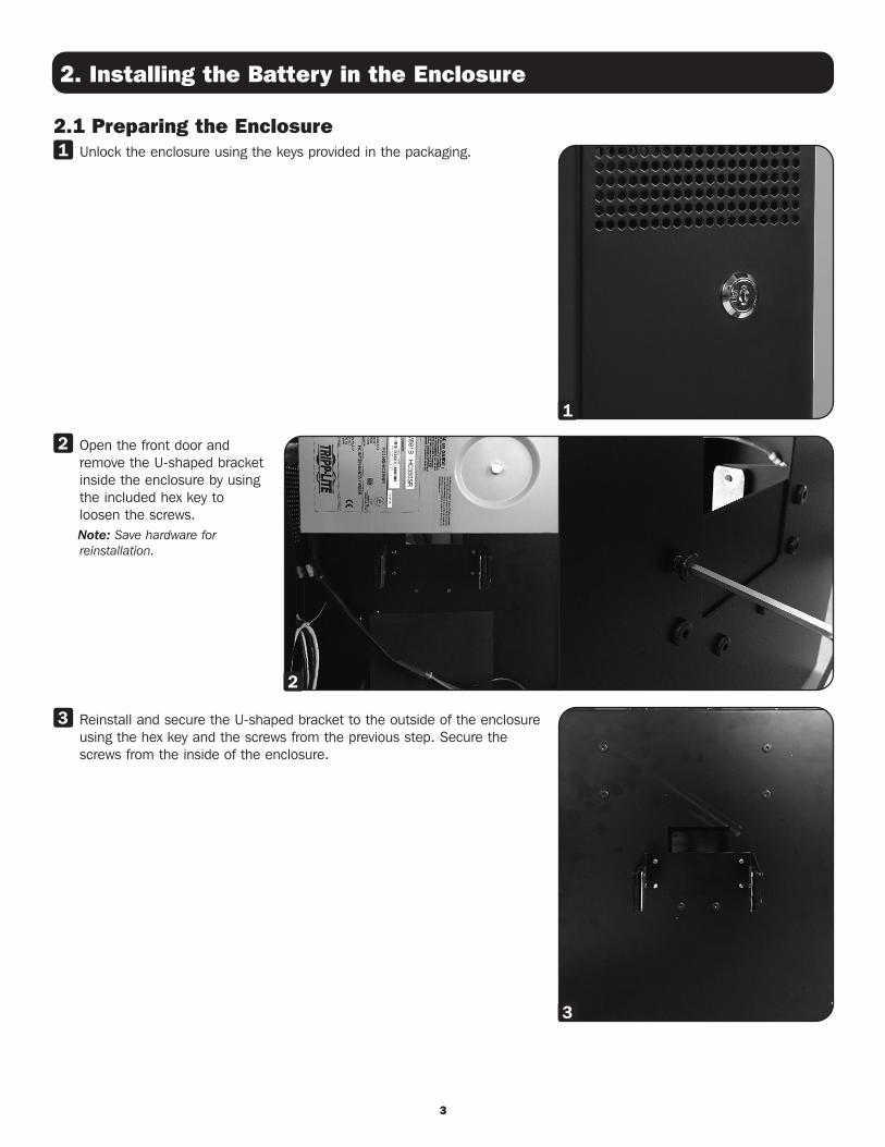
2.1 Preparing the Enclosure1 Unlock the enclosure using the keys provided in the packaging.
2 Open the front door and remove the U-shaped bracket inside the enclosure by using the included hex key to loosen the screws.
Note: Save hardware for reinstallation.
3 Reinstall and secure the U-shaped bracket to the outside of the enclosure using the hex key and the screws from the previous step. Secure the screws from the inside of the enclosure.
1
2
3

4
2. Installing the Battery in the Enclosure
3. Connecting the Battery to the Power Module
2.2 Installing the Battery1 Loosen the hex screws located on the outside of the enclosure to remove
the battery retention L-shaped bracket. Note: Save hardware for reinstallation.
2 Carefully slide the battery into the battery compartment. Note: The battery terminals must face toward the front door.
3 Carefully reinstall and secure the battery retention L-shaped bracket.
1
1 Remove the hardware (hex nut, split lock and flat washer) from the battery terminals.
Note: Save hardware for reinstallation.
2 Carefully connect and secure the red positive lug (+) to the red positive (+) battery terminal. Slide the red terminal cover over the terminal post.
3 Secure the yellow ground lug and the black negative (-) battery lug to the black negative (-) battery terminal using the stud. Slide the black terminal cover over the terminal post.
4 Close and secure the box before powering the unit.
2
3
4

5
4. Connecting the Power Cables
1 Connect the C13 connector on the input power cord to the AC inlet on the interactive touchscreen panel.
2 Connect the C14 connector on the AC input power cord to the output port on the power module.
3 The additional power cord connects the power module’s pigtail to a properly grounded outlet. Connect the C13 connector to the power module’s pigtail, and connect the 5-15P plug to a wall outlet or utility source.
Note: The power module will not turn “on” automatically in the presence of live utility power.
2
1
3
C14 Connector
C13 Connector
C13 Connector
5-15P Connector

6
5. Operational Guidelines for the Power Module
5.1 Connection to a Wall Outlet (Line Mode)1 After you plug the power module into a live AC outlet, the power module (in “Standby” mode) will automatically charge
the battery, but it will not supply power to the output outlet until it is turned “on.” The power LED (~) will not be illuminated.
2 The battery LEDs will illuminate to indicate the charge level of the battery.
3 Let the power module charge the battery for 2 to 4 hours prior to operating. All 4 LEDs above the battery icon will illuminate green on the Remote User Interface (RUI) when the battery is fully charged (approximately 13.5 VDC).
4 Press and hold the “On/Off” button for one second to turn “on” the power module. The alarm will beep once briefly after one second has passed. Release the button. The power LED (~) will stay illuminated. The same steps should be followed for powering down the power module.
5 Reference the Quick Start Guide to power and operate the Interactive Touchscreen.
5.2 Disconnection from a Wall Outlet (Battery Mode)1 Unplug the power module from the wall outlet.
2 The battery LED will begin to flash and the alarm will begin beeping.
3 Press the Mute button on the RUI to silence the alarm, or plug the power module back into the wall outlet to charge the battery.
Note: Unit will also supply power while in charge mode.
4 The power module will run from the charged battery.
5 LEDs on the RUI device will indicate the charge remaining in the battery.
6 When the battery is low (11.0 VDC), the alarm will start beeping. Cutoff is set at 10.5 VDC.
7 Plug the power module back into the wall outlet to charge the battery before the unit powers down.
Power LED Battery Charge Level LEDs
On/Off Button Mute Button

7
6. Attaching the Battery Box and Battery to the Mobile Cart
Caution! For safe installation, do not attempt to attach the battery box (with battery installed) to the mobile cart without adequate help.
1 Battery box and battery installation is the same for mobile cart models DMCS60100XX and DMCS3270XP. Move up the plastic handle on one of the cart’s columns, and insert the U-shaped bracket attached to the enclosure as shown.
Note: The battery box can be installed on either column.
1
2
3
2 Slide the enclosure down the column by inserting the bracket’s screws into the channels on each side of the column.
3 Adjust the height of the enclosure and firmly tighten the screws on each side of the bracket.
Note: Place the included spacer over the screw on the column to reduce any potential vibration between the cart and the enclosure.

8
1111 W. 35th Street, Chicago, IL 60609 USA • tripplite.com/support
20-10-253 93-3C27_RevB
Tripp Lite has a policy of continuous improvement. Specifications are subject to change without notice. Photos and illustrations may differ slightly from actual products.
Warranty
1-Year Limited Warranty Seller warrants this product, if used in accordance with all applicable instructions, to be free from original defects in material and workmanship for a period of 1 year from the date of initial purchase. If the product should prove defective in material or workmanship within that period, Seller will repair or replace the product, in its sole discretion.
THIS WARRANTY DOES NOT APPLY TO NORMAL WEAR OR TO DAMAGE RESULTING FROM ACCIDENT, MISUSE, ABUSE OR NEGLECT. SELLER MAKES NO EXPRESS WARRANTIES OTHER THAN THE WARRANTY EXPRESSLY SET FORTH HEREIN. EXCEPT TO THE EXTENT PROHIBITED BY APPLICABLE LAW, ALL IMPLIED WARRANTIES, INCLUDING ALL WARRANTIES OF MERCHANTABILITY OR FITNESS, ARE LIMITED IN DURATION TO THE WARRANTY PERIOD SET FORTH ABOVE; AND THIS WARRANTY EXPRESSLY EXCLUDES ALL INCIDENTAL AND CONSEQUENTIAL DAMAGES. (Some states do not allow limitations on how long an implied warranty lasts, and some states do not allow the exclusion or limitation of incidental or consequential damages, so the above limitations or exclusions may not apply to you. This warranty gives you specific legal rights, and you may have other rights which vary from jurisdiction to jurisdiction.)
WARNING: The individual user should take care to determine prior to use whether this device is suitable, adequate or safe for the use intended. Since individual applications are subject to great variation, the manufacturer makes no representation or warranty as to the suitability or fitness of these devices for any specific application.