baxter
DESCRIPTION
Advanced Energy TechnologiesTRANSCRIPT

Features / Control Sytstem / Absorption Cycle 02
Single Effect Double Lift Hot water Driven Absorption Machine
Double Effect Exhaust Gas DrivenAbsorption Machine
Waste Heat Recovery Absorption Machine
Single Effect Hot Water Driven Absorption Machine
Double Effect Direct Fired Absorption Chiller & Heater
Double Effect Steam Fired Absorption Chiller
Single Effect Steam Fired Absorption Chiller
Absorption Heat Pump
Installation Records
12
18
26
28
42
46
50
52
549
8
7
6
5
4
3
2
1
CONTENT
For Future Energy & Environment -
KTL KITECH
Absorption ChillerHeat Pump
World Energy

World Energy Co., Ltd. was founded for the purpose of developing and providing various types of waste-heat recovered and energy saving Absorption Machines such as Single Effect Double Lift Hot Water Driven Absorption Chiller, Single-Effect Hot Water Driven Absorption Machine, Double-Effect Exhaust Gas Driven Absorption Machine and Absorption Heat Pump. Thanks to an accumulated and international grade technologies of R&D and manufacturing, a highly-qualified engineers and also a cooperation with well-known world-class partners, the company is introducing high efficient chillers to the world market.
World Energy Co., Ltd. is playing a key role in Korean District Cooling and Heating industry. In cooperation with KDHC(Korea District Heating Corporation) and KARSE(Korean Association of AirConditioning, Refrigerating and Sanitary Engineers), the company introduced a new technology in Absorption Chiller and developed Certification Program for Absorption Chiller.
World Energy Co., Ltd. makes every effort to satisfy worldwide customers with high performing, reliable and international standard products. World Energy Co., Ltd. will continue to improve customers’ business interests by offering energy-saving products in the age of high energy cost, andfurthermore, to contribute to environmental protection.
Thank you.
Welcome to World Energy
Steam
Hot water
Exhaust gas
Recycleenergy
Wasteheat ->>
ㆍDeclaration of Conformity ㆍR&D Center Certificate ㆍUnderwriters Laboratories
ㆍEnvironmental Management System Certificate
ㆍQuality Management System Certificate

01
World Energy Milestone
02. 2004. Cooperate company starts05. 2006. 1st commercial operation of Single Effect 2-Lift Hot Water Driven Absorption Chiller (300RT, KDHC office, Korea)09. 2006. 1st Shipment to USA market (130RT, USA market)12. 2006. Complete Development of 1st Generation Single Effect 2-Lift Hot Water Driven Absorption Chiller (75~1125RT)02. 2007. 1st Development of Exhaust Gas Driven Simultaneous Absorption Chiller/Heater (UTC Power, USA)03. 2007. UL Listed08. 2007. Ethylene Glycol Chemical Plant application chillers delivered (HWAR-L 1000RT*3Units S Model*5 Units)12. 2007. Development of Heating Cycle with 2-Lift Absorption Chiller06. 2008. Shipment of Exhaust Heat of Methylene- Chloride Driven Absorption Chiller to Chemical Plant (Korea)09. 2008. Shipment of Large capacity (4708kW) Hot Water Driven Chiller to Chemical Plant(Korea)
10. 2008. 1st Shipment to EU market (Italy, 2Units/Hot Water Chiller)08. 2009. 1st Shipment of 2-Lift Hot Water Chiller to EU market (Germany)09. 2009. 1st Shipment of Waste Heat Recovery Absorption Chiller (2AA240, ZINC Factory, Korea)09. 2009. Complete Development of 2nd Generation Single Effect 2-Lift Hot Water Driven Absorption Chiller (75~1300RT)05. 2010. 1st Shipment of Single Effect 2 Lift Hot Water Chiller to Taiwan (2AB825, Nanya Plastic))06. 2010. 1st Shipment of Exhaust Gas Driven Chiller to EU market (IBM R&D Center, Germany)06. 2010. Shipment of 3,883kW MVR(Evaporating Condenser for Mechanical Vapor Compression System) to Chemical Plant (Korea)07. 2010. Shipment of Heat Exchanger for Fuel Cell to UTC Power, USA09. 2010. Shipment of the largest capacity(1025RT) Hot Water Driven Chillers to Commercial/ Residential complex district cooling application (Korea)
World Energy Co.
02 World Energy Co.
For Future Energy & Environment
Absorption Machines
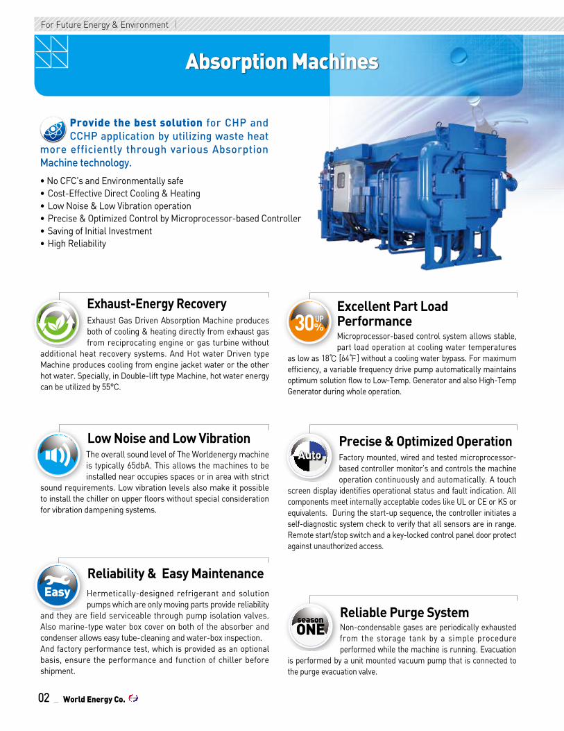
Hermetically-designed refrigerant and solution pumps which are only moving parts provide reliability
and they are field serviceable through pump isolation valves. Also marine-type water box cover on both of the absorber and condenser allows easy tube-cleaning and water-box inspection.And factory performance test, which is provided as an optional basis, ensure the performance and function of chiller before shipment.
Reliability & Easy Maintenance
Safe Easy
ONEseason
Microprocessor-based control system allows stable, part load operation at cooling water temperatures
as low as 18℃ [64℉] without a cooling water bypass. For maximum efficiency, a variable frequency drive pump automatically maintains optimum solution flow to Low-Temp. Generator and also High-Temp Generator during whole operation.
Excellent Part LoadPerformanceExhaust Gas Driven Absorption Machine produces
both of cooling & heating directly from exhaust gas from reciprocating engine or gas turbine without
additional heat recovery systems. And Hot water Driven type Machine produces cooling from engine jacket water or the other hot water. Specially, in Double-lift type Machine, hot water energy can be utilized by 55°C.
Exhaust-Energy Recovery
Safe Easy
ONEseason
The overall sound level of The Worldenergy machine is typically 65dbA. This allows the machines to be installed near occupies spaces or in area with strict
sound requirements. Low vibration levels also make it possible to install the chiller on upper floors without special consideration for vibration dampening systems.
Low Noise and Low Vibration
Safe Easy
ONEseasonSafe Easy
ONEseason
Factory mounted, wired and tested microprocessor-based controller monitor’s and controls the machine operation continuously and automatically. A touch
screen display identifies operational status and fault indication. All components meet internally acceptable codes like UL or CE or KS or equivalents. During the start-up sequence, the controller initiates a self-diagnostic system check to verify that all sensors are in range. Remote start/stop switch and a key-locked control panel door protect against unauthorized access.
Precise & Optimized Operation
Safe Easy
ONEseason
Non-condensable gases are periodically exhausted from the storage tank by a simple procedure performed while the machine is running. Evacuation
is performed by a unit mounted vacuum pump that is connected to the purge evacuation valve.
Reliable Purge System
Safe Easy
ONEseason
Provide the best solution for CHP and CCHP application by utilizing waste heat
more efficiently through various Absorption Machine technology.
• No CFC's and Environmentally safe • Cost-Effective Direct Cooling & Heating • Low Noise & Low Vibration operation• Precise & Optimized Control by Microprocessor-based Controller• Saving of Initial Investment• High Reliability
For Future Energy & Environment

03World Energy Co.
World Energy Absorption M
achines / Control System
Control System
Microprocessor-based Unit Controller is factory mounted, wired and tested to ensure a protection of the Machine and efficient capacity control. The program logic provides proper Start/Stop of the Machine and also enables a communication interface with others.
• Component Test and Diagnostic Check• Touch Screen Interface for Status Display, Set-point Control, and System Configuration• Primary and Secondary Status Messages• Individual Start/Stop Schedules for Local Mode• Recall of Up to 999 Alarm and Alert Messages with Diagnostic Help• Extensive Diagnostic and Service Capabilities• Advanced Crystallization Protection
Safety Cutouts• Solution Pump Motor Overload/High Temperature• Refrigerant Pump Motor Overload/High Temperature• Low Chilled Water Temperature Cutout• Low Refrigerant Temperature Cutout• Low Cooling Temperature Cutout• Low Chilled Water Flow Cutout • Low Cooling Water Flow Cutout (Option)• Generator High Temperature Cutout• Hot Water High Temperature Cutout (Low Temp. Hot Water Driven type only)• High Temperature Generator High Pressure Cutout (Exhaust Gas Driven type only)• High Temperature Generator Low Level Cutout (Exhaust Gas Driven type only)
Protective Limits• Strong Solution Leaving High Temperature Generator Alarm• Hot Water High Temperature Alarm (Low Temp. Hot Water Driven type only)• Refrigerant Pump Overload/High Temperature Alarm• Solution Pump Motor Overload/High Temperature Alarm• Low Refrigerant Temperature Alarm
• Low Chilled Water Temperature Alarm• Low Cooling Water Temperature Alarm• Low Chilled Water Flow Alarm
Overrides• Hot Water High Temperature (Low Temp. Hot Water Driven type only)• Generator Solution High Temperature• High Concentration
Temperature Sensor Faults• Leaving Chilled Water Temperature• Cooling Water Temperature Entering Absorber• Refrigerant Condensate Temperature from Condenser• Refrigerant Evaporating Temperature• Strong Solution Temperature Leaving Generator• Entering Hot Water Temperature (Low Temp. Hot Water Driven type only)• Exhaust Gas Temperature Cutout (Exhaust Gas Driven type only)
Capacity Control• Leaving Chilled Water Control• Running Travel Limit (Control Valve Opening Limit)
Indications• Chiller Operating Status Message• Absorption Cycle State Points• Dilution Cycle• Power-On• Alarm• Safety Shutdown Message• Run Hours• Control Valve Position
WORLD ENERGY
Microprocessor Touch Screen Control Panel
For Future Energy & Environment For Future Energy & Environment
Absorption Cycle
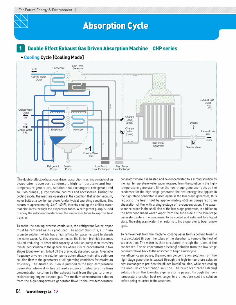
The double-effect, exhaust-gas driven absorption machine consists of an evaporator, absorber, condenser, high-temperature and low-temperature generators, solution heat exchangers, refrigerant and solution pumps , purge system, controls and accessories. During the cooling mode, the machine operates at the condition that under vacuum, water boils at a low temperature. Under typical operating conditions, this occurs at approximately 4.4oC (40oF), thereby cooling the chilled water that circulates through the evaporator tubes. A refrigerant pump is used to spray the refrigerant(water) over the evaporator tubes to improve heat transfer.
To make the cooling process continuous, the refrigerant (water) vapor must be removed as it is produced. To accomplish this, a lithium bromide solution (which has a high affinity for water) is used to absorb the water vapor. As this process continues, the lithium bromide becomes diluted, reducing its absorption capacity. A solution pump then transfers this diluted solution to the generators where it is re-concentrated in two stages (double-effect) to boil off the previously absorbed water. A variable frequency drive on the solution pump automatically maintains optimum solution flow to the generators at all operating conditions for maximum efficiency. The diluted solution is pumped to the high-temperature generator where it is heated and re-concentrated to a medium concentration solution by the exhaust heat from the gas turbine or reciprocating engine exhaust gas. The medium concentration solution from the high-temperature generator flows to the low-temperature
generator where it is heated and re-concentrated to a strong solution by the high temperature water vapor released from the solution in the high-temperature generator. Since the low-stage generator acts as the condenser for the high-stage generator, the heat energy first applied in the high-stage generator is used again in the low-stage generator, thus reducing the heat input by approximately 45% as compared to an absorption chiller with a single-stage of re-concentration. The water vapor released in the shell side of the low-stage generator, in addition to the now condensed water vapor from the tube side of the low-stage generator, enters the condenser to be cooled and returned to a liquid state. The refrigerant water then returns to the evaporator to begin a new cycle.
To remove heat from the machine, cooling water from a cooling tower is first circulated through the tubes of the absorber to remove the heat of vaporization. The water is then circulated through the tubes of the condenser. The re-concentrated (strong) solution from the low-stage generator flows back to the absorber to begin a new cycle.For efficiency purposes, the medium concentration solution from the high-stage generator is passed through the high-temperature solution heat exchanger to pre-heat the diluted (weak) solution, while pre-cooling the medium concentration solution. The re-concentrated (strong) solution from the low-stage generator is passed through the low-temperature solution heat exchanger to pre-heat/pre-cool the solution before being returned to the absorber.
04
M
Solution Pump
Refrigerant Pump
Low Temp.Heat Exchanger
High Temp.Heat Exchanger
Cooling WaterInlet
Cooling WaterOutlet
Chilled WaterOutlet
Chilled WaterInlet
AbsorberEvaporator
Low Temp. GeneratorCondenser
High Temp. Generator
Exhaust Gas Inlet
Diverter Valve
Exhaust Gas Outlet
Bypass
Change Valve(close)
Change Valve(close)
37℃
7℃
12℃
32℃
450℃
165℃
Double Effect Exhaust Gas Driven Absorption Machine _ CHP series1
• Cooling Cycle [Cooling Mode]
World Energy Co.

Absorption Cycle
WORLD ENERGY Absorption Cycle - CH
P Cooling & H
eating Mode
05
Solution Pump
Refrigerant Pump
Low Temp.Heat Exchanger
High Temp.Heat Exchanger
Cooling WaterInlet
Cooling WaterOutlet
Chilled WaterOutlet
Chilled WaterInlet
AbsorberEvaporator
Low Temp. GeneratorCondenser
MHigh Temp. Generator
Exhaust Gas Inlet
Diverter Valve
Exhaust Gas Outlet
Bypass
Change Valve(open)
Change Valve(open)
Solution Pump
Refrigerant Pump
Low Temp.Heat Exchanger
High Temp.Heat Exchanger
AbsorberEvaporator
Low Temp. Generator
Condenser
MHigh Temp. Generator
Exhaust Gas Inlet
Diverter Valve
Exhaust Gas Outlet
Hot water Inlet
Hot water Outlet
Bypass
Cooling WaterInlet
Cooling WaterOutlet
Chilled WaterOutlet
Chilled WaterInlet
Change Valve(close)
Change Valve(close)
Change Valve(close)
During the heating mode, the cycle follows a different vapor flow path than that undertaken for cooling and does not use the typical absorption process. In addition, the absorber-condenser cooling water circuit is drained and thus not operated, since all heat rejection from the machine is designed to take place through the evaporator (now the heating bundle) in a classic two-pipe system that utilizes only the evaporator nozzles. High temperature water vapor produced in the high-temperature generator section is passed directly to the evaporator via the absorber where it condenses and transfers its heat to the water circulating through the evaporator tubes.
Hot water temperature at 60oC (140oF)
Hot water temperature at 79oC (175oF)
This condensed water then flows to the absorber section where it mixes with the concentrated solution returning from the high-temperature generator. The diluted solution is then pumped back to the high-temperature generator to repeat the vapor generation phase for the heating function. Quick changeover from cooling to heating is accomplished by switching the positions of two hand valves, draining the absorber-condenser water circuit and putting the machine into heating mode by changing the position of a switch in the control panel.The hot water temperatures is 60oC (140oF) as a standard without additional components and 79oC (175oF) as an option with the additional heat exchanger.
• Heating Cycle [Heating Mode]
World Energy Co.

06
Double Effect Exhaust Gas Driven Absorption Chiller and Heater
For Future Energy & Environment
Absorption Cycle
For Future Energy & Environment
Single Effect Double Lift Hot Water Driven Absorption Machine _ 2AB series
Double Lift Hot water driven absorption chiller has main cycle and aux. cycleThe chilled water is cooled down in evaporator and the vaporized refrigerant is absorbed into concentrated solution which is coming from 2nd generator. The concentrated solution becomes diluted solution and the heat is absorbed into cooling water. The diluted solution in absorber flows to 1st generator through low temp. heat exchanger and high temp. heat exchanger, and 95oC of driving hot water heats up the diluted solution and refrigerant vapor is generated. The absorbent solution in 1st generator becomes intermediate solution and it flows to 2nd generator through high temp. heat exchanger.
Cooling Water Inlet
31℃
Evaporator Absorber
Aux. Absorber
Solution Pump
RefrigerantPump
Aux. Solution Pump
8℃
Refrigerant
Diluted Solution
Intermidiate Soution
Concentrated Solution
Chilled Water
Cooling Water
Hot Water
Chilled WaterOutlet
Aux. Concentrated Solution
Aux. Intermidiate Soution
Low Temp.Heat Exchanger
High Temp. Heat Exchanger
CondenserAux. Generator
ConcentratedSolution Pump
IntermediateSolution Pump
Aux. Heat Exchanger
Chilled WaterInlet
13℃
Hot WaterOutlet
55℃
Hot WaterInlet
95℃
Cooling WaterOutlet
36.5℃
34.5℃
57.1℃
74.5℃
80.0℃
60.2�C
65.2℃
37.8℃
33.5℃
34.3℃
38.9℃
5.5℃
56.2℃
40.1℃
36.5℃
51.2℃
54.6%
58.3%
59.9%
42.9%
45.2%
6.8 mmHg
52.2 mmHg
21.2 mmHg
63.5℃
73.1℃
The intermediated solution in 2nd generator is heated up by driving hot water and the refrigerant vapor is generated. The vaporized refrigerant from 2nd generator is absorbed into absorbent solution in aux. absorber and it becomes aux. diluted solution. The aux. diluted solution is delivered to aux. generator through aux. heat exchanger, and the solution is heated up by driving hot water return from 2nd generator and becomes aux. concentrated solution. The aux. concentrated solution is delivered to aux. absorber through aux. heat exchanger. The refrigerant vapors which are generated 1st generator and aux. generator are condensed in condenser and then flow into evaporator, and the heat in condenser is absorbed by cooling water.
2
World Energy Co.

07
Absorption Cycle - 2AB / 2AA / H
WAR
-L
Absorption Cycle
WORLD ENERGY
Single Effect Hot Water Driven Absorption Machine _ HWAR - L series
Cooling Water Inlet
31℃
Evaporator AbsorberChilled Water Inlet
Solution PumpRefrigerant Pump Exchanger
13℃
8℃
Refrigerant
Diluted Solution
Concentrated Solution
Chilled Water
Cooling Water
Hot Water
Chilled Water Outlet
Generator
Condedenser
36.5℃
Cooling Water Outlet
Hot Water Outlet
80℃
Hot WaterOutlet
95℃
4
Waste Heat Recovery Absorption Machine _ 2AA series
Cooling WaterInlet
31℃
Evaporator Absorber
Aux. Absorber
SolutionPump
RefrigerantPump
Aux. Solution Pump
8℃
Chilled WaterOutlet
SolutionHeat
Exchanger
Aux.Solution Heat Exchanger
Generator
Aux. Generator
Condenser
ConcentratedSolution Pump
Aux. ConcentratedSolution Pump
Chilled WaterInlet
13℃
Cooling WaterOutlet
36℃
70℃
Hot Water Outlet
Hot Water Inlet
60℃
Refrigerant
Diluted Solution
Concentrated Solution
Chilled Water
Cooling Water
Hot water
Aux. Concentrated Solution
Aux. Intermediate Solution
3
World Energy Co.

08
Double Effect Exhaust Gas Driven Absorption Chiller and Heater
For Future Energy & Environment
Absorption Cycle
For Future Energy & Environment
Absorber
RefrigerantPump Low Temp.
Heat Exchanger Heat Exchanger
Evaporator
Low Temp. GeneratorCondenser
ChangeValve(Close)
ChangeValve(Close)
Cooling Water Inlet
Chilled Water Outlet
SolutionPump High Temp.
Cooling Water Outlet
Gas Inlet
High Temp.Generator
Exhaust Gas
Cooling Water
Refrigerant
Refrigerant Vator
Concentrated Solution
Diluted Solution
Intermediate Solution
Chilled Water Inlet
Chilled Water
7℃
12℃
37.5℃
32℃
Concentrated Solution
Intermediate Solution
55℃
60℃
Absorber
RefrigerantPump
Low Temp.Heat Exchanger Heat Exchanger
Evaporator
Low Temp. GeneratorCondenser
ChangeValve(Open)
ChangeValve(Open)
Cooling Water Inlet
Hot Water Outlet
SolutionPump
High Temp.
Cooling Water Outlet
Gas Inlet
High Temp.Generator
Exhaust Gas
Hot Water
Refrigerant
Refrigerant Vator
Diluted Solution
Hot Water Inlet
Double Effect Direct Fired Absorption Chiller & Heater _ DW series5• Cooling Cycle [Cooling Mode]
• Heating Cycle [Heating Mode]
World Energy Co.

09
Absorption Cycle - DW
Cooling & H
eating Mode / SW
/ S
Absorption Cycle
WORLD ENERGY
Absorber
RefrigerantPump
SolutionPump Low Temp.
Heat ExchangerHigh Temp.
Heat Exchanger
Evaporator
Cooling WaterInlet
Chilled WaterOutlet
Chilled WaterInlet
Cooling Water
Refrigerant
Refrigerant Vator
Concentrated Solution
Diluted Solution
Intermediate Solution
Chilled Water
Steam Inlet
DrainOutlet
Steam DrainReclaimer
Steam
SteamTrap
High Temp.Generator
Low Temp. GeneratorCondenser
Cooling Water Outlet
Double Effect Steam Fired Absorption Chiller _ SW Series6
Cooling WaterInlet
Evaporator Absorber
Chilled Inlet
Solution PumpRefrigerant Pump Heat Exchanger
Refrgerant
Concentrated Solution
Diluted Solution
Chilled Water
Cooling Water
Steam
Chilled Outlet
Generator
Condenser
Cooling Outlet
Steam Inlet
Steam DrainReclaimer
DrainOutlet
Refrgerant Vator
Single Effect Steam Fired Absorption Chiller _ S Series7
World Energy Co.

10
Double Effect Exhaust Gas Driven Absorption Chiller and Heater
For Future Energy & Environment
Double Effect Exhaust Gas Driven Absorption Chiller and Heater
Waste Hot water
Hot Water
Refrigerant
Refrigerant Vator
Steam
Concentrated Solution
Diluted Solution
SolutionHeat Exchanger
AbsorberEvaporator
Waste Hot waterOutlet
RefrigerantPump
SolutionPump Hot Water
Inlet
Drain Outlet
Steam InletHot WaterOutlet
Condenser Generator
Waste Hot waterInlet
Gas Inlet
Waste Hot water
Hot Water
Refrigerant
Refrigerant Vator
Concentrated Solution
Diluted Solution
SolutionHeat Exchanger
AbsorberEvaporator
Waste Hot waterOutlet
RefrigerantPump
Hot WaterPump
Hot Water Inlet
Waste Hot waterInlet
Condenser
Generator
Hot Water Outlet
Exhaust Gas
Absorption Cycle
Absorption Heat Pump Cycle8
For Future Energy & Environment
• Steam Fired Type _ HPS series
• Direct Fired Type _ HPD series
World Energy Co.

11
Absorption Cycle - HPS / H
PD / AH
T Heat Pum
pWORLD ENERGY
Waste Heat
Hot Water
Refrigerant
Refrigerant Vator
Concentrated Solution
Diluted Slution
SolutionHeat Exchanger
CondenserGenerator
RefrigerantPump
Solution Pump
Hot Water Outlet
Absorber
Hot Water Inlet
Evaporator
RefrigrantCirlculration Pump
Cooling Water Outlet
Cooling Water Inlet
Waste HeatOutlet
Waste HeatInlet
Cooling Water
(Heat source : Hot Water or Drain)
(Heat source : Hot Water or Drain)
Absorption Cycle
• Steam Generation Type _ AHT series
• Duhring Diagram _ 2AB Series
World Energy Co.
DUEHRING DIAGRAM
SOLUTION TEMPERATURE [°C]
PR
ESSU
RE
[mm
Hg]
100
100
50
50
40
40
30
30
20
20-20
10
10-10
543
21
0
0% 40% 50% 60%
70%
60 70 80 90
59.4
23.6
6.6
HOT WATERINLET 95°C
COOLING WATEROUTLET 36.5°C
COOLING WATERINLET 31°C
CHILLED WATER8°C 13°C
33.3°C
34.3°C
69.7°C81.6°C
14.3%44
.9%
56.2
%58
.9%
61.5%
HOT WATEROUTLET 55°C

12
Note1. Working pressure of each water side is based on 1.0MPa (150psig).2. Lowest outlet temperature of chilled water is 5oC and 18oC for cooling water.3. Controllable cooling capacity range shall be 25~100% as a standard condition and 0~100% as an option.
4. Each water flow can be adjusted within 50~120%.5. Fouling factor 0.0001m2.h.oC/kcal for Absorber and Condenser, 0.0001m2.h.oC/kcal for Evaporator and Generator.6. 79oC of hot-water temperature is possible as an option.
Performance DataDouble Effect Exhaust Gas Driven Type (50~400RT)
For Future Energy & Environment For Future Energy & Environment
Double Effect Exhaust Gas Driven Absorption Machine
CHP005 CHP006 CHP007 CHP008 CHP010 CHP012 CHP015 CHP018 CHP021 CHP024 CHP028 CHP032 CHP036 CHP040
kW
kW
usRT
℃
mAq
mAq
mAq
mmAq
mm*mm
kg/sec
℃
℃
℃
℃
m3/h
Mcal/h
mm
mm
mm
mm
mm
mm
mm
mm
kW
kW [A]
kW [A]
kW [A]
kW [A]
kW [A]
A
ton
ton
ton/h
m3/h
50
176
30.2
4.0
50
7.0
142
165
30
4.0
0.439
58
782*291 782*369782*330 782*408 922*408 922*486 922*603 922*642 922*681 922*681 922*798 922*876 1376*720 1376*759
1,683
3.0
3.2
60
211
36.3
3.7
60
6.1
170
197
36
3.7
0.527
58
1,722
3.2
3.5
70
246
42.3
6.2
70
10.2
198
230
42
6.2
0.615
74
1,761
3.7
4.0
80
281
48.4
5.6
80
9.6
227
263
48
5.6
0.703
71
1,800
3.9
4.3
100
351
60.5
4.8
100
11.1
283
329
60.5
4.8
0.88
77
1,857
5.0
5.4
120
422
72.6
5.1
120
11.3
340
395
72.6
5.1
1.05
82
1,935
5.3
2,0901800 2,147 2,399
4,8724,7423,7173,6802,63826002100
10.8 11.9
0.3 (1.2)
400
10080
100 125 150 200
15012510080
125 150
0.4 (1.4)
2.4 (6.9)
500
500
3.2 (9.0)
600
600
2.0 (6.4)
400
1.5 (5.5)
300
0.2 (1.0)
300
0.2 (0.5)
0.4 (2.5)
450 / 125
55.3 / 60
32 / 37.5
12 / 7
450 / 165
0.4 (1.4)
3ø, 400V, 50Hz
12.6 14.7
5.8
150
527
90.7
6.6
150
11.5
425
494
90.7
6.6
1.32
79
2,052
6.4
7.0
180
633
109
7.0
180
11.8
510
592
109
7.0
1.58
92
2,091
6.8
7.4
210
738
127
6.4
210
11.8
595
691
127
6.4
1.84
97
2,194
7.9
8.6
240
844
145
6.3
240
12.1
680
790
145
6.3
2.11
113
2,194
8.5
9.3
280
984
169
4.6
280
11.2
793
922
169
4.6
2.46
129
2,310
9.8
10.7
320
1125
194
4.5
320
10.7
906
1053
194
4.5
2.81
131
2,349
10.3
11.3
360
1265
218
5.0
360
11.1
1019
1185
218
5.0
3.16
123
2,349
12.8
14.0
400
1406
242
5.1
400
10.8
1133
1317
242
5.1
3.51
131
2,349
13.2
14.6
Model
Cooling Capacity
Inlet Temp./Outlet Temp.
Flow rate
P. Drop
ChilledWater
Cooling Water
HotWater
ExhaustGas
Electric
Size
Weight
Connection
Inlet Temp./Outlet Temp.
Flow rate
P. Drop
Connection
Heating Capacity
Inlet Temp./Outlet Temp.
Flow rate
P. Drop
Connection
Flow rate
CoolingTemp.
Heating
Pressure Drop
Inlet Conn.
Outlet Conn
Diverter Valve
Power source
Abs. Pump
Control Panel
Amp.(400Vac)
Lenght (L)
Width (W)
Height (H)
Rigging
Operation
Unit
Sealing Blower
Ref. Pump
Purge Pump
World Energy Co.

1
CHP Perform
ance Data
13
Note1. Working pressure of each water side is based on 1.0MPa (150psig).2. Lowest outlet temperature of chilled water is 5oC and 18oC for cooling water.3. Controllable cooling capacity range shall be 25~100% as a standard condition and 0~100% as an option.
4. Each water flow can be adjusted within 50~120%.5. Fouling factor 0.0001m2.h.oC/kcal for Absorber and Condenser, 0.0001m2.h.oC/kcal for Evaporator and Generator.6. 79oC of hot-water temperature is possible as an option.
Performance DataCHP045 CHP050 CHP056 CHP063 CHP070 CHP080 CHP090 CHP100 CHP110 CHP120 CHP130 CHP140 CHP150
kW
kW
usRT
℃
mAq
mAq
mAq
mmAq
mm*mm
kg/sec
℃
℃
℃
℃
m3/h
Mcal/h
mm
mm
mm
mm
mm
mm
mm
mm
kW
kW [A]
kW [A]
kW [A]
kW [A]
kW [A]
A
ton
ton
ton/h
m3/h
350300250200
32 / 37.5
12 / 7
450
1582
272
4.4
450
10.7
1274
250 300 350 400
1481
272
4.4
3.95
1376*837
4,954
2,491
15.7
17.2
500
1757
302
3.9
500
10.8
1416
1646
302
3.9
4.39
200
1376*915
2,569
16.5
2,633
14.7
3.2 (9.0)
600
600
2,962
20.7
3,380
23.3
0.2 (0.5)
450 / 125
55.3 / 60
450 / 165
0.4 (2.5)
3ø, 400V, 50Hz
1.5 (4.0)
0.75 (2.2)0.4 (1.4)
0.3 (1.2)
5.5 (15.0)
750
750
7.5 (24.0)
1000
1000
33.1
3,500 3,700
18.1
560
1968
339
3.6
560
7.7
1586
1843
339
3.6
4.92
1376*1008
4,998
2,934
21.2
23.7
630
2214
381
5.0
630
10.6
1784
2074
381
5.0
5.53
1376*1143
5,540
3,069
23.1
25.8
700
2460
423
6.6
700
14.0
1982
2304
423
6.6
6.15
1376*1233
6,038
3,159
24.6
27.5
800
2812
484
4.7
800
8.7
2266
2633
484
4.7
7.03
1376*1218
5,644
3,330
31.0
34.8
900
3163
544
6.4
900
11.8
2549
2962
544
6.4
7.91
250
1376*1368
6,142
3,480
33.6
37.6
1000
3515
605
8.5
1000
15.6
2832
3291
605
8.5
8.78
1376*1418
6,667
3,530
35.6
39.9
1100
3866
665
7.2
1100
3.0
3115
3621
665
7.2
9.66
1376*1418
6,293
4,348
41.1
46.2
1200
4218
726
9.2
1200
3.8
3398
3950
726
9.2
10.54
300
1376*1518
6,818
4,448
43.4
48.8
1300
4569
786
11.5
1300
4.8
3682
4279
786
11.5
11.42
1376*1668
7,318
4,598
46.4
52.1
1400
4921
847
8.3
1400
4.0
3965
4608
847
8.3
12.30
350
1376*1818
6,974
4,932
50.2
56.5
1500
5272
907
10.2
1500
4.8
4248
4937
907
10.2
13.18
1376*2068
7,475
5,182
54.1
60.8
133 143134 133 146 155 153 176 213 221 212 206 184
Model
Cooling Capacity
Inlet Temp./Outlet Temp.
Flow rate
P. Drop
ChilledWater
Cooling Water
HotWater
ExhaustGas
Electric
Size
Weight
Connection
Inlet Temp./Outlet Temp.
Flow rate
P. Drop
Connection
Heating Capacity
Inlet Temp./Outlet Temp.
Flow rate
P. Drop
Connection
Flow rate
CoolingTemp.
Heating
Pressure Drop
Inlet Conn.
Outlet Conn
Diverter Valve
Power source
Abs. Pump
Control Panel
Amp.(400Vac)
Lenght (L)
Width (W)
Height (H)
Rigging
Operation
Unit
Sealing Blower
Ref. Pump
Purge Pump
Double Effect Exhaust Gas Driven Type (450~1500RT)
Double Effect Exhaust Gas Driven Absorption Machine
WORLD ENERGY
CHP Series
World Energy Co.

K/2 A
H
I
BE
D
C
J/2
J
K
F F
G G
Absorber, Evaporator, Condenser& Low Temperature Generator Shell Assembly
High TemperatureGenerator Assemply
Note1. Drain ditch should be prepared around foundation.2. Horizontal level of foundaton surface should be maintained less than 1mm per 1m.3. indicates the location of anchor bolts. (Anchor bolt, nut and steel plates are not supplied)
Nut
Welding
Anchor Bolt
Steel Plate
Machine Feet
Drain DitchFoundation
50
Example of Anchoring
14
Double Effect Exhaust Gas Driven Absorption Chiller and Heater
For Future Energy & Environment
Double Effect Exhaust Gas Driven Absorption Machine
For Future Energy & Environment
Foundation
322322400400400500600600641641800800816816800900
1,0001,1001,2001,2001,4001,4001,4001,5001,7001,8002,100
3,8564,3984,8964,3484,8465,3714,8965,4215,9215,3715,871
1,941
1,421
1,921
2,961
2,936
3,956
3,906990
900
1,150
1,210
1,290
1,500
1,600
2,500
2,400
1,4041,567
1,370
1,010
1,3071,453
1,386
700
800
1,194
1,033
973
200
125
150
400
300 500
325
350
100
100
50 150
200125 325
200
215
205
205
115
105
105
236236236236382371292292289289267287342342352341445463458486461486
1,1711,1711,1461,1311,106
1.01.11.21.32.02.12.52.63.13.43.94.15.15.36.26.48.89.610.312.413.414.417.318.319.421.122.4
0.50.60.70.80.70.81.01.11.21.31.41.51.92.02.42.63.03.33.54.95.45.65.86.16.67.18.0
CHP005CHP006CHP007CHP008CHP010CHP012CHP015CHP018CHP021CHP024CHP028CHP032CHP036CHP040CHP045CHP050CHP056CHP063CHP070CHP080CHP090CHP100CHP110CHP120CHP130CHP140CHP150
Model A(mm)
B(mm)
C(mm)
D(mm)
E(mm)
H(mm)
I(mm)
J(mm)
K(mm)
F(ton)
G(ton)
World Energy Co.

15
ExhaustDuct
VerticalDuct
DiverterValve
ExhaustGas
BypassExhaust
High StageGenerator
Double Effect Exhaust Gas Driven Absorption Machine
1
WORLD ENERGY CH
P Foundation / System Pipings
ABSORPTION CHILLER
Engine
Exhaust gas Outlet
Diverter Valve
Exhaust Gas Bypass
Exhaust gas Inlet
Air Fuel
Air Handling Unit
Flow meterChilled / Hot water Pump(1st)
Chilled / Hot water Pump(2nd)
Bypass valve
Supply Header Return Header
F P T
P T
D
Cooling water Outlet
P T
Air ventAV
Cooling Tower
Bleed off
Drain line
CoolingwaterPump
P T
Cooling water Inlet
Chilled water Inlet
Chilled water Outlet
Strainer
Bypass valve
Thermostat
Pressure gaugeP
T Temperature Gauge
Damper valve
Valve
Supply water
Expansion Tank
1) All external equipment out of dotted line is scope of customer's.2) Refer to outline drawing and specification data sheet for the external
dimensions of the machine, the location & the diameter of water pipe connection and the dimensions & the size of Exhaust gas line connections.
3) The locations of chilled water pumps, cooling water pumps and expansion tanks shall be determined in consideration of the hydrostatic head of pumps and the height of building. And the Machine shall not be subject to a pressure higher than the designed pressure at any water header.
4) For cooling water quality control, it is recommended to install cooling water bleed-off device on the inlet pipe line of cooling towers.
5) Around 10 meshes of strainers are recommended to be installed in the cooling water line.
6) For the maintenance and the inspection of the Machine, the following equipment shall be installed on each chilled water and cooling water inlet/outlet lines as well as stop valve.• Thermometers and pressure gauges shall be installed at chilled and cooling water inlet/outlet.• Air relief valves shall be installed on each chilled and cooling water lines at higher points than each water headers.• Drain valves shall be installed at the lowest position between the stop valves of chilled and cooling water and the Machine and the drain valve shall be piped to the drain ditch.
7) There shall be a sufficient clearance for access to the absorber, evaporator, condenser, and generator to facilitate inspection and cleaning work.
For Diverter Valve;1) Install the diverter valve at the exhaust gas duct end of gas turbine or
reciprocating engine and level the diverter valve horizontally by using the level gauge.
2) Install the transient duct between high-stage generator and diverter valve.
3) Connect the wiring in accordance with wiring diagram of the manufacturer.
System Pipings
For Exhaust Gas Duct;1) Sharp bend and restrictions should be avoided to allow smooth gas
flow.2) The exhaust gas duct outlet should be arranged to prevent the rain
water from entering into the machine and the drain connection should be provided to remove the condensate from the exhaust gas outlet side.
Diverter Valve & Exhaust Gas Duct
CHP Series
World Energy Co.

16
Double Effect Exhaust Gas Driven Absorption Machine
For Future Energy & Environment
Thermal Insulation
CHP045CHP050CHP056CHP063CHP070CHP080CHP090CHP100CHP110CHP120CHP130CHP140CHP150
20.621.323.424.725.332.133.734.236.537.639.341.143.9
3.13.17.58.39.210.511.513.015.516.818.218.119.6
75mm 50mmModel(mm) 19mm
Hot Surface (m2)10mm 19mm
Cold Surface (m2)10mm
12.412.49.59.59.511.011.411.813.714.014.314.615.1
1.21.21.41.41.51.61.61.71.71.71.81.81.8
7.911
13.5151617
18.520
22.522.223.426.627.6
0.40.40.60.70.71.11.21.21.41.41.41.51.5
CHP005CHP006CHP007CHP008CHP010CHP012CHP015CHP018CHP021CHP024CHP028CHP032CHP036CHP040
8.28.28.28.29.510.411.211.412.813.614.118.218.418.4
0.90.90.91.11.81.82.22.22.222.22.52.53.03.0
75mm 50mmModel(mm) 19mm
Hot Surface (m2)10mm 19mm
Cold Surface (m2)10mm
3.93.93.94.25.15.27.57.58.58.510.210.211.311.3
0.40.40.40.30.70.70.70.70.70.91.11.11.21.2
2.62.62.62.63.63.64.84.85.85.87.17.17.97.9
0.30.30.30.30.30.30.30.30.30.40.40.40.40.4
Note1. Use only Non-inflammable or Incombustible insulation materials.2. Do not insulate motor of refrigerant pump.3. Total insulation area includes piping.4. Do not cover components such as service valves, dampers, diaphragm valves, sight glass, control valves or thermometers or sensor wells.5. The standard Material and Thickness as the recommendation :
6. For insulation area for each model, please refer to the picture below.7. The water box sections should be worked to be disassembled for the repair.8. If necessary, please perform the finish painting in the field after completing the insulation work.
HOT Surface insulation
Wrapping Material when Glass wool is used.
• Material of insulation : Glass wool, Thermal Conductivity 0.04kcal/m·h·℃
• Thickness of insulation : 50mm (2 inch), 75mm (3 inch)• Material of insulation : Closed cell type Non-inflammable polymer sponge• Thickness of insulation : 10mm (3/8inch), 19mm (3/4inch) INSULATION
CHP-SERIES
10mm(3/8inch) : Inlet and Outlet Piping of Refrigerant Pump
19mm(3/4inch) : Evaporator Body and It's Water Box
19mm(3/4inch) : Heat Exchanger Body It's Low temperature Box(Inlet, Outlet) Low Temperature Generator Body and It's Outlet(ABSO, Refrigerant) Box
50mm(2inch) : High Heat Exchanger Box and It's High Temperoture Piping, Steam Box
INSULATION FOR HOT SURFACES
INSULATION FOR COLD SURFACES
75mm(3inch) : High Temperature Generator
10mm(3/8inch) : Low Temperature Piping
NOTES1. Use only Non-inflammable or Incombustible insulation materials2. Do not insulate motor of refrigerant pump.3. Total insulation area includes piping.4. Do not cover components such as service valves, dampers, diaphragm valves, sight-glass, control valves or thermometers or sensor wells.5. The standard Material and Thickness as the recommendation : (1) HOT Surface insulation ■ Material of insulation : Glass wool, Thermal Conductivity 0.04kcal/m ·h·℃ ■ Thickness of insulation : 50mm (2 inch), 75mm (3 inch) ■ Material of insulation : Closed cell type Non-inflammable polymer sponge ■ Thickness of insulation : 10mm (3/8inch), 19mm (3/4inch)(2) COLD Surface insulation ■ Material of insulation : Closed cell type Non-inflammable polymer sponge ■ Thickness of insulation : 10mm (3/8inch), 19mm (3/4inch) (3) Wrapping Material when Glass wool is used. ■ Insulated parts on body : Colored galvanized steel with 0.45mm thickness or over ■ Insulated parts on pipes : Colored galvanized steel with 0.30mm thickness or over6. For insulation area for each model, please refer to the picture below.7. The water box sections should be worked to be disassembled for the repair.8. If necessary, please perform the finish painting in the field after completing the insulation work.
L90605
World Energy Co.,LTD.
F
E
D
2 3 4
C
B
A
1 2 3 4
5 6 7 2A (594x420 95g/m ) 2
F
E
D
5 6 7
C
B
8
A
21DATE : 2011.02.10.
TIT.PRJ DWG NO.
UNIT :SCALE :
DWG NAME
• Insulated parts on body : Colored galvanized steel with 0.45mm thickness or over• Insulated parts on pipes : Colored galvanized steel with 0.30mm thickness or over
World Energy Co.
19mm : Evaporator Body with Water Box10mm : Inlet and Outlet Piping of
Refrigerant Pump
Cold Surface75mm : High Temp. Generator
50mm : High Heat Exchanger Box
with High Temperature Piping,
Steam box
19mm : Heat Exchanger Body
with Low Temperature Box,
Low temperature Generator Body
with Outlet Box
10mm : Low temperature Piping
Hot Surface
INSULATION
CHP-SERIES
10mm(3/8inch) : Inlet and Outlet Piping of Refrigerant Pump
19mm(3/4inch) : Evaporator Body and It's Water Box
19mm(3/4inch) : Heat Exchanger Body It's Low temperature Box(Inlet, Outlet) Low Temperature Generator Body and It's Outlet(ABSO, Refrigerant) Box
50mm(2inch) : High Heat Exchanger Box and It's High Temperoture Piping, Steam Box
INSULATION FOR HOT SURFACES
INSULATION FOR COLD SURFACES
75mm(3inch) : High Temperature Generator
10mm(3/8inch) : Low Temperature Piping
NOTES1. Use only Non-inflammable or Incombustible insulation materials2. Do not insulate motor of refrigerant pump.3. Total insulation area includes piping.4. Do not cover components such as service valves, dampers, diaphragm valves, sight-glass, control valves or thermometers or sensor wells.5. The standard Material and Thickness as the recommendation : (1) HOT Surface insulation ■ Material of insulation : Glass wool, Thermal Conductivity 0.04kcal/m ·h·℃ ■ Thickness of insulation : 50mm (2 inch), 75mm (3 inch) ■ Material of insulation : Closed cell type Non-inflammable polymer sponge ■ Thickness of insulation : 10mm (3/8inch), 19mm (3/4inch)(2) COLD Surface insulation ■ Material of insulation : Closed cell type Non-inflammable polymer sponge ■ Thickness of insulation : 10mm (3/8inch), 19mm (3/4inch) (3) Wrapping Material when Glass wool is used. ■ Insulated parts on body : Colored galvanized steel with 0.45mm thickness or over ■ Insulated parts on pipes : Colored galvanized steel with 0.30mm thickness or over6. For insulation area for each model, please refer to the picture below.7. The water box sections should be worked to be disassembled for the repair.8. If necessary, please perform the finish painting in the field after completing the insulation work.
L90605
World Energy Co.,LTD.
F
E
D
2 3 4
C
B
A
1 2 3 4
5 6 7 2A (594x420 95g/m ) 2
F
E
D
5 6 7
C
B
8
A
21DATE : 2011.02.10.
TIT.PRJ DWG NO.
UNIT :SCALE :
DWG NAME
COLD Surface insulation• Material of insulation : Closed cell type Non-inflammable polymer sponge• Thickness of insulation : 10mm (3/8 inch), 19mm (3/4 inch)

Double Effect Exhaust Gas Driven Absorption Machine
1
WORLD ENERGY CH
P Thermal Insulation / Start-up Sequence
17
Start-up Sequence
Ref PumpTimer elapsed
No
Start RefrigerantPump
Machine Running
Yes
Start 3 minRefrigerant Pump
Delay Timer
StartRequest
Verify All sensorsin range
In Prestart safties
Yes
ModeCooling 79 deg C HeatingStart Chilled
Water Pump
Start WaterVerify Timer
Verify ChilledWater Flow
Verify timerelapsed
No
No
Yes
Start CoolingWater Pump
Start WaterVerify Timer
Verify CoolingWater Flow
Yes
Water timerElapsed
No
No
Yes
Start TowerControl
Yes
Start-Stop Condition
No
Monitor forStart-Stop
Yes
StartSolutionPump
Chilled WaterFault
Cooling WaterFault
Sensor Fault /Prestart Alerts
60 deg C Heating
A B
No
No
CHP Series
World Energy Co.

Single Effect Double Lift Hot Water Driven Absorption Machine
18
For Future Energy & Environment
Single Effect Double Lift Hot water Driven Type (75~375RT)
ㆍ2AB180 (Korea)
Note1. Working pressure of chilled/cooling water circuits are based on 1.0Mpa
(150psig) and 1.6MPa (230psig) for driving hot water circuit.2. Standard flow rate of chilled water per usRT is 0.6048m3/h, 1.42m3/h
for cooling water and 0.1187ton/h for hot water.3. Fouling factor 0.0001m2.h.oC/kcal for Absorber and Condenser, 0.0001m2.h.oC/kcal for Evaporator and Generator.
Performance DataModel Unit 2AB075
264
45.4
107
9.0
9.4
3.1
4.4
116
2.2
5.1
425
241
10.3
129
10.8
11.2
3.3
4.6
130
3.2
5.3
466
263
10.8
125
157
13.2
13.7
2.9
5.7
152
4.7
6.6
548
316
2.3 (8.8)
0.2 (1.1)
65
5.2
193
16.2
16.8
3.5
6.0
174
3.0
7.0
610
350
5.8
222
18.6
19.3
3.1
7.2
234
3.9
8.4
779
423
50
5.9
150
257
21.6
22.4
3.3
7.5
252
5.2
8.9
852
466
0.4 (1.5)
0.2 (0.5)
3.1 3.2 3.5 3.6 4.2
14.313.311.9 12.3
2,658 3,678 3,720 4,740
2,109
2,257
1,834
2,084
2,400 3,400 4,500
4,872
2,248
2,519
4,882
2,430
2,787
80
3ø, 400V, 50Hz
6.3
300
25.2
26.2
6.7
8.8
286
2.9
10.4
910
519
40
11.4
343
28.8
29.9
6.9
9.2
310
3.7
10.9
1,008
576
2.6 (9.8)
65
11.3
200
386
32.4
33.7
6.3
11.3
356
4.7
13.4
1,353
695
100
3.2 (10.8)
0.4 (1.5)0.3 (1.5)
10.8
429
36.0
37.4
6.3
11.8
381
2.3
14.1
1,460
758
10.6
250
486
40.8
42.4
6.2
13.5
509
3.0
16.2
1,729
895
80
11.0
536
45.0
46.8
6.2
14.0
536
3.6
16.9
1,827
968
11.3
75
3.7
kW
usRT
℃
m3/h
mH20
mm
℃
m3/h
mH20
mm
℃
ton/h
m3/h
mH20
mH20
mm
mm
-
kW (A)
kW (A)
kW (A)
kW (A)
kW
A
mm
mm
mm
ton
ton
mm
2AB090
316
54.4
90
3.8
80 100 125
31 / 36.5
95 / 55
150 200
2AB110
387
66.5
110
4.6
2AB135
475
81.6
135
4.8
2AB155
545
93.7
155
4.1
2AB180
633
109
180
4.6
12 / 7
2AB210
738
127
210
3.2
2AB240
844
145
240
3.4
2AB270
949
163
270
3.4
2AB300
1,055
181
300
3.5
2AB340
1,196
206
340
3.1
2AB375
1,319
227
375
3.2ChilledWater
Cooling Water
HotWater
Electric
Size
Weight
Water Volume of Machine
Chilled Water Side
Cooling Water Side
Hot Water Side
Cooling Capacity
Inlet Temp./Outlet Temp.
Inlet Temp./Outlet Temp.
Flow rate
Flow rate
P. Drop
Connection
Inlet Temp./Outlet Temp.
Flow rate
Connection
Control Valve
Power source
Abs. Pumps
Ref. Pump
Purge Pump
Control Panel
Total kW
Lenght (L)
Width (W)
Height (H)
Rigging
Operation
Shell
Control Valve
PressureDrop
P. Drop
Connection
Total Ampere
Space for Tube Replacement
World Energy Co.

Single Effect Double Lift Hot Water Driven Absorption Machine
2
WORLD ENERGY 2AB
Performance D
ata
19
2AB Series
Single Effect Double Lift Hot water Driven Type (420~1,300RT)Performance Data2AB420
1,477
254
601
50.4
52.4
5.6
19.0
619
1.8
23.0
2,448
1,050
9.9
672
56.4
58.6
7.6
20.7
674
2.2
25.0
2,625
1,153
13.5
300
751
63.0
65.5
8.0
22.2
724
2.8
26.9
5,700
2,788
1,247
5.6 (18.6)
100
12.7
858
72.0
74.8
5.3
26.7
970
3.6
31.6
5,200
3,567
1,561
9.5
965
81.0
84.2
3.4
28.7
1,037
4.6
34.0
5,700
3,776
1,684
100
12.9
350
1,073
90.0
93.5
4.4
30.7
1,106
2.2
36.3
6,200
3,996
1,813
7.7 (25.0)
0.4 (1.5)
0.2 (0.5)
6.6 9.8 11.9 15.2
51.838.331.022.1
4,998 5,540 6,038 5,654 6,152 6,677 6,258
3,140
3,471
2,788
3,036
4,500 5,200
6,783 7,283
3,531
3,837
7,010 7,510 8,510
4,430
4,000
125
3ø, 400V, 50Hz
16.9
1,180
99.0
103
3.7
36.4
1,373
2.6
43.1
5,700
4,938
2,040
10.1
1,287
108
112
4.6
38.4
1,459
3.2
45.5
6,200
5,206
2,201
9.4 (31.5)
125
12.9
400
1,394
117
122
5.6
40.8
1,541
3.7
48.3
6,700
5,461
2,354
150
12.7 (45.0)
1.5 (4.0A)
0.75 (2.3)
0.4 (1.6)
16.1
1,502
126
131
4
43.4
1,970
4.3
52.5
7,200
7,867
2,810
12.5
450
1,609
135
140
4.8
46.1
2,083
2.2
55.7
7,700
8,193
2,994
150
15.3
1,859
156
162
7
53.1
2,309
2.9
64.1
8,200
8,844
3,363
14.5
420
3.1
kW
usRT
℃
m3/h
mH20
mm
℃
m3/h
mH20
mm
℃
ton/h
m3/h
mH20
mH20
mm
mm
-
kW (A)
kW (A)
kW (A)
kW (A)
kW
A
mm
mm
mm
ton
ton
mm
2AB470
1,653
284
470
4.3
200 250
31 / 36.5
95 / 55
300
2AB525
1,846
318
525
5.7
2AB600
2,110
363
600
4.1
2AB675
2,373
408
675
5.5
2AB750
2,637
454
750
7.2
12 / 7
2AB825
2,901
499
825
4.0
2AB900
3,165
544
900
5.1
2AB975
3,428
590
975
6.3
2AB1050
3,692
635
1,050
5.2
2AB1125
3,956
680
1,125
6.3
2AB1300
4,571
786
1,300
8.8ChilledWater
Cooling Water
HotWater
Electric
Size
Weight
Chilled Water Side
Cooling Water Side
Hot Water Side
Cooling Capacity
Inlet Temp./Outlet Temp.
Inlet Temp./Outlet Temp.
Flow rate
Flow rate
P. Drop
Connection
Inlet Temp./Outlet Temp.
Flow rate
Connection
Control Valve
Power source
Abs. Pumps
Ref. Pump
Purge Pump
Control Panel
Total kW
Lenght (L)
Width (W)
Height (H)
Rigging
Operation
Shell
Control Valve
PressureDrop
P. Drop
Connection
Total Ampere
Space for Tube Replacement
Model Unit
Water Volume of Machine
Options1. High Pressure water Boxes Water boxes rated for 250psig or 300psig working pressure shall be furnished when specified on the equipment specification data.
2. Special Tubes Tubes of non-standard materials and/or wall thickness shall be provided when specified on the equipment specification data.
3. Special operation temperature conditions Special operation temperature shall be provided when specified on the equipment specification data.
World Energy Co.

20
Single Effect Double Lift Hot Water Driven Absorption Machine
For Future Energy & Environment
2AB 075 / 090
Outline_Foudation
1547
3200
0
R650
2658(L)
Control Panel
781
63
2004
2113
1941
1309
1928
680
0
0
Cooling waterOutlet(125A)
80
854
904
1376
168
2084(H
)
1834(W)
0
EvaporatorAbsorber
Condenser
Aux.Absorber
1'stGenerator
2'ndGenerator
Aux.Generator
2114
2074
653
1452
1957
882
1230
0
0
Hot waterOutlet(65A)
Hot waterInlet(65A)
Cooling waterInlet(125A)
Chilled waterInlet(80A)
Chilled waterOutlet(80A)
0
0
2084(H
)
80
854
904
1376 0 0
0
1834(W)
Cooling waterOutlet(150A)
Control Panel
168
Hot waterOutlet(65A)
Hot waterInlet(65A)
Cooling waterInlet(150A)
Chilled waterInlet(100A)
Chilled waterOutlet(100A)
4200
0
EvaporatorAbsorber
Condenser
Aux.Absorber
1'stGenerator
2'ndGenerator
Aux.Generator
3678(L)
1474 63
3024
3134
2961
1928
680
3134
3094
627
1452
1957
895
1217
1978
1547
R650
0
552
372
1326
150
0 2961
125325
1456
1656
5010
080
100
FRONT
REAR
0
552
372
1326
150
0
1941
125325
1456
1656
50
100
80
100
FRONT
REAR
2AB 110 / 135
Clearance for tube removalat either side
Clearance for tube removalat either side
1. Indicates the position of anchor bolt holes.2. All external water piping are to be provided by the customer.3. Indicates the position of the power supply wiring connections to control panel.4. Installation and service clearance : • Longitudinal Distance : 1m • Top : 0.2m • Control Panel : 1.2m • Others : 0.5m
World Energy Co.

0
660480
1594
150
0
3956
150350
1724
1924
5010
080
100
FRONT
REAR
0
660480
1594
150
0
2936
150350
1724
1924
5010
080
100
FRONT
REAR
Single Effect Double Lift Hot Water Driven Absorption Machine
2
WORLD ENERGY 2AB
Outline_Foudation
21
0
4200
Clearance for tube removal at either side
0
EvaporatorAbsorber
Condenser
Aux.Absorber
1'stGenerator
2'ndGenerator
Aux.Generator
0
Hot waterOutlet(80A)
Hot waterInlet(80A)
Cooling waterInlet(150A)
0
Chilled waterInlet(125A)
Chilled waterOutlet(125A)
0
0
Cooling waterOutlet(150A)
Control Panel
1815
R650
1014
1064
1644
175
3146
3091
705
1620
2125
1018
1370
1481
1985
75
2936
3011
3146
2081
830
3720(L)
80
2257(H
)
2109(W)
1815
0
R650
80
1014
1064
1644
1680
2257(H
)
2109(W)
2082
2003
2506 75
3956
4031
830
0
0
Cooling waterOutlet(200A)
4740(L)
4166
654
1370
1620
2125
210
4166
Hot waterOutlet(80A)
0
0
Hot waterInlet(80A)Chilled water
Outlet(125A)
Cooling waterInlet(200A)
1018
0
Chilled waterInlet(125A)
4111
5200
EvaporatorAbsorber
Condenser
Aux.Absorber
1'stGenerator
2'ndGenerator
Aux.Generator
Control Panel
2AB 155 / 180
2AB 210 / 240
Clearance for tube removalat either side
Clearance for tube removalat either side
1. Indicates the position of anchor bolt holes.2. All external water piping are to be provided by the customer.3. Indicates the position of the power supply wiring connections to control panel.4. Installation and service clearance : • Longitudinal Distance : 1m • Top : 0.2m • Control Panel : 1.2m • Others : 0.5m
Outline_Foudation
2AB Series
World Energy Co.

22
Single Effect Double Lift Hot Water Driven Absorption Machine
For Future Energy & Environment
2AB 340 / 375
0 0 0
0 0
2430(W)
5300
R650
2049
1660
Chilled waterOutlet(200A)
2430
Hot water Outlet(100A)
Hot water Inlet(100A)
Cooling waterInlet(250A)
Chilled waterInlet(200A)
EvaporatorAbsorber
Condenser
Aux.Absorber
1'stGenerator
2'ndGenerator
Aux.Generator
Control Panel
Cooling waterOutlet(250A)
0
1926
100
4006
4171
3906
105
1085
1125
1883
190
265
4171
4096
2587
1100
4882(L)
2787(H
)
609
1971
2657
1122
0
833
618
1813
170
0 3906
200400
1988
2188
70
100
105
100
FRONT
REAR
2AB 270 / 300
2319
980
0
1000
2519(H
)
2248(W)
105
1005
1045
1699
1900
1489
258
41710
0
4096
576
1773
2389
1052
0
Control Panel
4164
Cooling waterOutlet(250A)
Chilled waterOutlet(150A)
Hot water Outlet(100A)
Hot water Inlet(100A)
Cooling waterInlet(250A)
Chilled waterInlet(150A)
5300
R650
1865
0
EvaporatorAbsorber
Condenser
Aux.Absorber
1'stGenerator
2'ndGenerator
Aux.Generator
2016
2520
3906
4006
4171
4872(L)
0
729
514
1629
170
0
200400
1804
2004
7010
0
3906
105
100
FRONT
REAR
Clearance for tube removalat either side
Clearance for tube removalat either side
1. Indicates the position of anchor bolt holes.2. All external water piping are to be provided by the customer.3. Indicates the position of the power supply wiring connections to control panel.4. Installation and service clearance : • Longitudinal Distance : 1m • Top : 0.2m • Control Panel : 1.2m • Others : 0.5m
Outline_Foudation
World Energy Co.

Single Effect Double Lift Hot Water Driven Absorption Machine
2
WORLD ENERGY 2AB
Outline_Foudation
23
2AB 420 / 470 / 525
2AB 600 / 675 / 750
0
Cooling waterOutlet(300A)
Control Panel
2788(W)
0
EvaporatorAbsorber
Condenser
Aux.Absorber
1'stGenerator
2'ndGenerator
Aux.Generator
2903
0
Hot water Outlet(100A)
0
0
Hot water Inlet(100A)
Cooling waterInlet(300A)
Chilled waterInlet(200A)
R650
2330
0
Chilled waterOutlet(200A)
2811
1150
3036(H
)
105
1253
1283
21690
125
215
634
2085
1149
1769
3140(W)
3471(H
)
105
1413
1443
2423 0
EvaporatorAbsorber
Condenser
Aux.Absorber
1'stGenerator
2'ndGenerator
Aux.Generator
2831
309
1500
643
3200
1000
0
Cooling waterOutlet(350A)
Control Panel
657
2356
1299
0
1993
Hot water Inlet(125A)
Cooling waterInlet(350A)
Chilled waterInlet(250A)
Chilled waterOutlet(250A)
3330
0
Hot water Outlet(125A)
250 0
2518
0
R650
0
1015
780
2323
200
0
300500
2528
2728
100
100
105
100
FRONT
REAR
0
921
686
2069
200
0
250
450
2274
2474
100
100
105
100
FRONT
REAR
2AB600A
B
C
D
E
F
G
H
I
J
2AB675 2AB7505654434844984708501127552183470845985200
6152484649965206550929382366520650965700
6677537155215731603431632591573156216200
I
2AB420A
B
C
D
E
F
G
H
I
2AB470 2AB525499838563981417124051901415140714500
554043984523471326472143469346135200
603848965021521128952391519151115800
A
J
I HE D CB F G
B
Clearance for tube removalat either side
Clearance for tube removalat either side
A
ED C B
B
F GH D
1. Indicates the position of anchor bolt holes.2. All external water piping are to be provided by the customer.3. Indicates the position of the power supply wiring connections to control panel.4. Installation and service clearance : • Longitudinal Distance : 1m • Top : 0.2m • Control Panel : 1.2m • Others : 0.5m
Outline_Foudation
2AB Series
World Energy Co.

24
Single Effect Double Lift Hot Water Driven Absorption Machine
For Future Energy & Environment
2AB 825 / 900 / 975
2AB 1050 / 1125 / 1300
3541
1000
0
1500
699
3531(W)
3837(H
)
105
1573
1603
2713 0
3173
358
250 0
667
2612
3671
1427
0
2199
Cooling waterOutlet(400A)
Hot water Inlet(125A)
Cooling waterInlet(400A)
Chilled waterInlet(300A)
Chilled waterOutlet(300A)
Hot water Outlet(125A)
R650
Control Panel
2808
0
EvaporatorAbsorber
Condenser
Aux.Absorber
1'stGenerator
2'ndGenerator
Aux.Generator
0
808
2662
3834
0
105
2035
2085
3315 0
3835
595
4430(W)
4000(H
)
965
1500
866
1565
0
2154
850
3631
0
Control Panel
ChilledwaterInlet(350A)
Chilled waterOutlet(350A)
Cooling waterOutlet(500A)
Hot waterInlet(150A)
Cooling waterInlet(500A)
Hot waterOutlet(150A)
3410
0
R800
EvaporatorAbsorber
Condenser
Aux.Absorber
1'st Generator
2'ndGenerator
Aux.Generator
FRONT
REAR
200
500
300
3420
100
3620
100
100
0
0
105
1030
1285
3215
0
1145
910
2613
200
0
300500
2818
3018
100
100
105
100
FRONT
REAR
A
J
E D CB F G I H
B
2AB1050A
B
C
D
E
F
G
H
I
J
2AB1125 2AB13007010537155215781614426431921
5881
57067200
7510587160216281664428932171
6281
62067700
8475687170217281764433932671
7282
72068200
2AB825A
B
C
D
E
F
G
H
I
J
2AB900 2AB9756258484649965231555929182351
523150965700
6783537155215756608431582591
575656216200
7283587160216256658434082841
625661216700
A
J
E D CB
B
F I HG
Clearance for tube removalat either side
Clearance for tube removalat either side
1. Indicates the position of anchor bolt holes.2. All external water piping are to be provided by the customer.3. Indicates the position of the power supply wiring connections to control panel.4. Installation and service clearance : • Longitudinal Distance : 1m • Top : 0.2m • Control Panel : 1.2m • Others : 0.5m
Outline_Foudation
World Energy Co.

2
WORLD ENERGY
25
10 mm : 냉매펌프의 입출구 배관
19 mm : 증발기 동체와 워터박스
19 mm : 제1재생기 동체와 워터박스, 제2재생기, 보조재생기 동체와 워터박스, 고온·저온·보조열교환기
보 온 부
보 냉 부
NOTES1. 보온보냉재는 불에 타지 않는 불연성 재질을 사용하여 주십시요. 2. 펌프의 모터는 보온보냉 하지 않습니다.3. 보온보냉 면적의 합계에는 냉동기내의 배관류의 면적도 포함됩니다.4. 서비스밸브, 댐퍼, 다이아프램 밸브, 싸이트글라스, 제어밸브, 온도계, 센서류 등은 보온보냉재 외부에 둘출되어야 합니다.5. 재질과 두께의 추천사양 (1) 보온부 ■ 재질 : 120°C에서 사용가능한 불연성 발포고무 ■ 두께 : 두께 : 10mm( 3
8 inch), 19mm( 34 inch)
(2) 보냉부 ■ 재질 : 불연성의 발포고무 ■ 두께 : 10mm( 3
8 inch), 19mm( 34 inch)
6. 모델별 보온면적은 좌측의 표와 아래의 그림을 참조하여 주십시요.7. 워터박스의 카바 및 펌프류는 분해·보수를 위해 탈착이 가능한 구조로 작업해 주십시요.8. 보온작업 완료 후 필요하다면 상도 도장을 하여 주십시요.
기종
2AB752AB902AB1102AB1352AB1552AB1802AB2102AB2402AB2702AB3002AB3402AB3752AB4202AB4702AB5252AB6002AB6752AB7502AB825
19두께(mm) 10 19 10
보온면적(m 2)
4.0 0.4
5.45.4
11.4 2.5 6.1 0.5
7.4 0.67.68.2
9.89.8
13.5 0.715.0 0.816.0 0.816.3 1.317.8 1.319.4 1.319.5 1.4
4.0
6.1 0.5
8.2
0.60.60.60.60.6
보냉면적(m 2)
0.40.40.4
2AB900 21.2 1.42AB975 25.7 1.4
10 mm : 보온부의 입출구 배관
7.37.39.89.8
14.314.316.0
18.718.721.723.625.428.430.332.135.1
11.4
16.0
37.038.8
2.22.22.22.2
2.52.53.3
3.93.94.64.64.65.45.45.45.9
2.5
3.3
5.95.9
27.0 1.540.7 6.228.4 1.542.8 6.229.8 1.544.9 6.2
2AB10502AB11252AB1300
EvaporatorAbsorber
Condenser
Aux.Absorber
1'stGenerator
2'ndGenerator
Aux.Generator
Control Panel
Model Hot Surface(m2) Cold Surface(m2)
(mm) 19mm 10mm 19mm 10mm
42.8
44.9
6.2
6.2
28.4
29.8
1.5
1.5
23.6 4.6 15.0 0.8
35.1 5.9 19.5 1.4
28.4 5.4 16.3 1.3
38.3 5.9 25.7 1.4
21.7 4.6 13.5 0.7
32.1 5.4 19.4 1.3
25.4 4.6 16.0 0.8
37.0 5.9 21.2 1.4
30.3 5.4 17.8 1.3
40.7 6.2 27.0 1.5
2AB420
2AB470
2AB525
2AB600
2AB675
2AB750
2AB825
2AB900
2AB975
2AB1050
2AB1125
2AB1300
Model Hot Surface(m2) Cold Surface(m2)
(mm)
2AB075
2AB375
19mm 10mm 19mm 10mm
18.7
18.7
3.9
3.9
9.8
9.8
0.6
0.6
7.3 2.2 4.0 0.4
14.3 2.5 7.4 0.6
9.8 2.2 5.4 0.4
16.0 3.3 8.2 0.6
7.3 2.2 4.0 0.4
11.4 2.5 6.1 0.5
9.8 2.2 5.4 0.4
14.3 2.5 7.6 0.6
11.4 2.5 6.1 0.5
16.0 3.3 8.2 0.6
2AB090
2AB110
2AB135
2AB155
2AB180
2AB210
2AB240
2AB270
2AB300
2AB340
Thermal Insulation
2AB Series Single Effect Double Lift Hot Water Driven Absorption Machine
Note1. Use only Non-inflammable or Incombustible insulation materials.2. Do not insulate motor of refrigerant pump.3. Total insulation area includes piping.4. Do not cover components such as service valves, dampers, diaphragm valves, sight glass, control valves or thermometers or sensor wells.5. The standard Material and Thickness as the recommendation :
6. For insulation area for each model, please refer to the table below.7. The water box sections should be worked to be disassembled for the repair.8. If necessary, please perform the finish painting in the field after completing the insulation work.
HOT Surface insulation
COLD Surface insulation
• Material of insulation : Non-inflammable polymer sponge usable at 120°C • Thickness of insulation : 19mm (3/4 inch), 10mm (3/8 inch) when polymer sponge is used
• Material of insulation : Closed cell type Non-inflammable polymer sponge• Thickness of insulation : 10mm (3/8 inch), 19mm (3/4 inch)
2AB O
utline_Foundation / Thermal Insulation
World Energy Co.
Hot Surface
19mm : 1st Generator with water box, 2nd Generator with water box, Aux. Generator with water box, Heat Exchanger body
10mm : Pipes of High temperature’s parts
Cold Surface
19mm : Evaporator with water box
10mm : Inlet and outlet pipes of refrigerant pump

Waste Heat Recovery Absorption Machine
26
For Future Energy & Environment
ㆍ2AA240(Zinc Factory, Korea)
2AA075 2AA090 2AA110 2AA135 2AA155 2AA180 2AA210 2AA240 2AA270 2AA300 2AA340 2AA375
kW
usRT
℃
m3/h
m3/h
mH20
mH20
mm
℃
℃
m3/h
mH20
mH20
mm
mm
mm
kW
kW (A)
kW (A)
kW (A)
kW (A)
-
A
mm
mm
mm
ton
ton
ton/h
mm
264
75
45.4
3.7
156
4.7
55.1
56.3
5.8
1.9
3.8
14.1
4.8
5.6
316
90
54.4
3.8
188
5.0
66.1
67.6
6.5
2.7
3.8
0.2 (1.1) 0.3 (1.5)
14.1
5.1
5.8
387
110
66.5
4.6
229
12.0
80.7
82.6
5.3
4.0
3.9
14.5
6.3
7.3
475
135
81.6
4.8
281
13.0
99.1
101.4
6.1
2.9
3.9
14.5
6.6
7.7
545
155
93.7
4.3
323
13.0
113.8
116.4
6.7
3.8
4.8
16.2
7.9
9.2
3,400 4,5002,400
2,084 2,257
2,623
3.8 (12.6)
100
125
125
200 250 300150
80 100 125 150 200
100 150
150
200
4.8 (15.2)
200
3.0 (11.0)
0.2 (0.5)
0.4 (1.5)
70 /60
31 / 36
13 / 8
0.4 (1.6)
3ø, 400V, 50Hz
2,281
633
180
109
4.6
375
13.4
132.1
135.2
7.1
5.2
4.8
16.2
8.3
9.8
738
210
127
3.2
438
7.1
154.1
157.7
5.9
3.1
4.8
16.2
9.7
11.4
844
240
145
3.4
500
7.1
176.2
180.2
6.2
4.1
4.8
16.2
10.1
12.0
949
270
163
3.4
563
7.3
198.2
202.8
5.6
5.1
5.8
18.8
12.4
14.7
1,055
300
181
3.5
625
7.2
220.2
225.3
5.7
1.4
5.8
18.8
13.0
2,540
3,7203,6782,658 4,740 4,776 4,880
2,795
15.5
1,196
340
206
3.1
709
7.1
249.6
255.3
5.5
1.8
5.8
18.8
14.9
2,838
3,022
17.8
1,319
375
227
3.2
782
7.2
275.3
281.6
5.7
2.2
5.8
18.8
15.4
18.6
Inlet Temp./Outlet Temp.
Flow rate
Connection
Control Valve
Shell
ControlValve
PressureDrop
Cooling Capacity
ChillrdWater
Inlet Temp./Outlet Temp.
Flow rate
Pressure Drop
Connection
CoolingWater
HotWater
Electric
Size
Weight
Inlet Temp./Outlet Temp.
Flow rate
Pressure Drop
Connection
Power source
Ref. Pump
Abs. Pump
Purge Pump
Control Panel
Total kW
Total Ampere
Length (L)
Width (W)
Height (H)
Rigging
Operation
Space for Tube Replacement
Performance DataWaste Heat Recovery (Single Effect Hot Water) Driven Type (75~375RT)
Model Unit
Note1. Working pressure of chilled water/cooling water circuit are based on
1.0Mpa [150psig].2. Fouling factor 0.0001m2.h.oC/kcal for Absorber and Condenser, 0.0001m2.h.oC/kcal for Evaporator.3. Standard power source is 3ph, 400V, 50Hz. Available 220, 380, 440V and
460V Power source.4. Catalogue specifications are subject to change without prior notice.
World Energy Co.

Waste Heat Recovery Absorption Machine
3
WORLD ENERGY 2AA Perform
ance Data
27
2AA Series
2AA420 2AA470 2AA525 2AA600 2AA675 2AA750 2AA825 2AA900 2AA975 2AA1050 2AA1125 2AA1300
kW
usRT
℃
m3/h
m3/h
mH20
mH20
mm
℃
℃
m3/h
mH20
mH20
mm
mm
mm
kW
kW (A)
kW (A)
kW (A)
kW (A)
-
A
mm
mm
mm
ton
ton
ton/h
mm
1,477
420
254
875
308.3
315.4
6.3
2.8
10.2
20.9
30.6
25.3
4,998
4,500
5.6
3.1
1,653
470
284
979
345.0
353.0
7.6
3.5
10.2
22.8
30.6
27.5
5,540
5,200
7.6
4.3
1,846
525
318
1,094
385.4
394.3
4.1
4.4
10.2
24.4
30.6
29.6
6,038
5,700
6.8
5.7
2,110
600
363
1,250
440.4
450.6
3.3
2.5
11.3
29.4
33.0
34.8
5,654
5,200
5.1
4.1
2,373
675
408
1,407
495.5
5.609
4.4
3.1
11.3
31.6
33.0
37.4
6,158
5,700
6.9
5.5
250
400
250 300
250
9.2 (27.0)
0.4 (1.6)
0.4 (1.5)
3,467
3,222
3,905
3,600
4,477
3,850
5,202
4,000
0.75 (2.3)
0.2 (0.5)
10.4 (35.0)
1.5 (4.0)
18.0 (64.0)
200 300
400
500
200
350 450
300
31 / 36
70 / 60
13 / 8
3ø, 400V, 50Hz
2,637
750
454
1,563
550.5
563.3
5.8
3.9
11.3
33.8
33.0
39.9
6,683
6,200
9.0
7.2
2,901
825
499
1,719
606
620
4.0
4.7
12.9
40.0
41.8
47.4
6,293
5,700
6.7
5.4
3,165
900
544
1,876
661
676
5.1
1.8
12.9
42.2
41.8
50.1
6,818
6,200
8.6
6.9
3,428
975
590
2,032
716
732
6.3
2.1
12.9
44.9
41.8
53.1
7,318
6,700
10.7
8.6
3,692
1,050
635
2,188
771
789
4.8
2.4
20.5
47.4
70.8
57.7
7,008
7,200
6.6
5.2
3,956
1,125
680
2,345
826
845
5.8
2.8
20.5
50.7
70.8
61.7
7,508
7,700
8.1
6.3
4,571
1,300
786
2,709
954
976
8.5
3.7
20.5
58.4
70.8
70.5
8,475
8,200
10.8
9.4
Inlet Temp./Outlet Temp.
Flow rate
Connection
Control Valve
Shell
ControlValve
PressureDrop
Electric
Size
Weight
Power source
Ref. Pump
Abs. Pump
Purge Pump
Control Panel
Total kW
Total Ampere
Length (L)
Width (W)
Height (H)
Rigging
Operation
Space for Tube Replacement
Performance DataWaste Heat Recovery (Single Effect Hot Water) Driven Type (420~1300RT)
Cooling Capacity
ChillrdWater
Inlet Temp./Outlet Temp.
Flow rate
Pressure Drop
Connection
CoolingWater
Inlet Temp./Outlet Temp.
Flow rate
Pressure Drop
Connection
Model Unit
HotWater
Note1. Working pressure of chilled water/cooling water circuit are based on
1.0Mpa [150psig].2. Fouling factor 0.0001m2.h.oC/kcal for Absorber and Condenser, 0.0001m2.h.oC/kcal for Evaporator.3. Standard power source is 3ph, 400V, 50Hz. Available 220, 380, 440V and
460V Power source.4. Catalogue specifications are subject to change without prior notice.
World Energy Co.

28
Single Effect Low Temperature Hot Water Absorption Chiller
For Future Energy & Environment
Single Effect Hot Water Driven Absorption Machine
Note1. Working pressure of chilled/cooling water circuits are based on 1.0MPa (150psig) and 1.6MPa (230psig) for driving hot water circuit.2. Standard flow rate of chilled water per usRT is 0.6048m3/h, 1.321m3/h for cooling water and 0.280ton/h for hot water.3. Fouling factor 0.0001m2.h.oC/kcal for Absorber and Condenser, 0.0001m2.h.oC/kcal for Evaporator and Generator.4. High temperature (100 ~ 150 degree C) Hot Water Driving type is available as additional model. Followings are the standard capacity range and the standard operational condition for the model selection; - Cooling capacity range as Standard model : 100 ~ 1300RT - Hot water Inlet / Outlet temperature : 138 / 108 degree C - Chilled water Inlet / Outlet temperature : 12 / 7 degree C - Cooling water Inlet / Outlet temperature : 32 / 39 degree C
Single Effect Hot Water Driven Type (30~300RT)Performance Data
30
4.9
6.3
0.8
2.1
40
140
57
2.3
50
9.7
12.6
1.9
2.2
187
80
2.9
1,077 1,095 1,495
2,540
75
10.4
10.9
1.5
5.0
312
112
4.1
80 100 125 150
110 135
9.6
10.8
0.7
4.3
432
148
5.2
155
9.6
11.3
0.9
3.3
644
198
6.4
210
9.8
11.0
1.6
2.4
715
252
7.9
270
10.3
10.9
1.6
4.0
327
10.4
40
5.1
6.6
1.1
3.8
161
69
2.5
1,900
2,095 2,598 2,597 3,680
7.57.1
3,708
9.6
4,734 4,776
2,400 2,400 3,400 4,500
2,257
1,472
10.6
1,244
2,255
0.3 (1.5)0.2 (1.1) 0.4 (1.6)
1.5 (4.0) 2.0 (6.0) 2.4 (7.0)
6550
50 8065
80
150 200125100
100
100
1.2 (4.0)
1,880
65
60
10.6
14.0
2.2
3.2
198
90
3.1
90
11.0
7.2
1.6
7.1
344
124
4.2
13 / 8
95 / 80
0.2 (0.5)
0.4 (1.5)
3ø, 380V, 50Hz
31 / 36.5
180
9.7
11.9
1.0
4.5
698
221
6.8
240
9.6
10.5
1.6
3.2
786
283
8.4
300
10.6
10.6
1.6
5.0
993
359
10.9
105
18.1
39.6
8.4
54
2.1
176
30.2
66.1
14
73
2.6
264
45.4
99.1
21
117
3.6
387
66.5
145
30.8
155
4.6
545
93.7
205
43.4
234
5.5
738
127
277
58.8
286
6.8
949
163
357
75.6
356
8.8
141
24.2
52.8
11.2
61
2.2
211
36.3
79.3
16.8
77
2.7
316
54.4
119
25.2
129
3.7
475
10.6
11.6
0.8
2.5
480
166
5.5
81.6
178
37.8
173
4.8
633
109
238
50.4
252
5.8
844
145
317
67.2
310
7.1
1,055
181
396
84
381
9.2
L030 L040 L050 L060 L075 L090 L110 L135 L155 L180 L210 L240 L270
kW
usRT
℃
m3/h
mH20
mm
℃
m3/h
mH20
mm
℃
ton/h
mH20
mH20
mm
mm
-
kW (A)
kW (A)
kW (A)
kW (A)
A
mm
mm
mm
ton
ton
mm
ChilledWater
Cooling Water
HotWater
Electric
Size
Weight
Cooling Capacity
Inlet Temp./Outlet Temp.
Inlet Temp./Outlet Temp.
Flow rate
Flow rate
P. Drop
Connection
Inlet Temp./Outlet Temp.
Flow rate
Connection
Control Valve
Power source
Abs. Pumps
Ref. Pump
Purge Pump
Control Panel
Lenght (L)
Width (W)
Height (H)
Rigging
Operation
Shell
Control ValvePressure
Drop
P. Drop
Connection
Model Unit
Space for Tube Replacement
Total Ampere
Water Volume of Machine
Chilled Water Side
Cooling Water Side
Hot Water Side
L300
World Energy Co.

Single Effect Hot Water Driven Absorption Machine
4
WORLD ENERGY L-Perform
ance Data
29
HWAR - L Series
Options1. High Pressure water Boxes Water boxes rated for 250psig or 300psig working pressure shall be furnished when specified on the equipment specification data.2. Special Tubes Tubes of non-standard materials and/or wall thickness shall be provided when specified on the equipment specification data.3. Special operation temperature conditions Special operation temperature shall be provided when specified on the equipment specification data.
Single Effect Hot Water Driven Type (340~1300RT)Performance Data
340
9.4
10.7
1.6
2.4
1,296
347
12.5
420
7.5
6.2
1.6
3.7
1,865
423
17.8
1,575
2,838
1,830
525
4.6
11.4
3.0
2.6
2,125
504
20.8
250 300 350
675 750
4.6
9.7
2.5
4.3
3,132
725
26.1
5,700
825
4.0
10.9
2.6
1.9
4,001
905
31.8
975
6.4
17.3
4.1
2.7
4,435
1,045
37.5
1,125
6.4
14.0
4.2
3.6
5,675
1,217
43.2
375
9.8
10.7
1.6
3.0
1,405
388
13.1
4,500
4,880 5,5404,998 6,1425,6446,038 6,667
17.010.6 14.6
6,8186,293 7,3606,8607,318
5,200 5,2005,700 6,200 5,700
4,000
2,329 2,929
22.8
2,206
3,600
0.4 (1.6) 1.5 (4.0)
3.0 (11.0)
125
125 150
150
350 400300250
200
200
2.4 (7.0) 4.5 (16.0)
3,222
200
470
10.3
8.5
2.2
4.7
2,001
463
19.4
600
3.4
7.2
1.8
3.4
2,963
672
23.3
13 / 8
95 / 80
0.2 (0.5)
0.4 (1.5) 0.75 (2.3)
3ø, 380V, 50Hz
31 / 36.5
900
5.2
13.9
3.3
2.3
4,223
970
34.6
1,050
5.2
13.8
3.4
3.1
5,426
1,146
40.3
1,196
206
449
95.2
463
10.5
1,477
254
555
118
580
14.7
1,846
318
694
147
669
17.2
2,373
408
892
189
1,045
21.6
2,901
499
1,090
231
1,439
26.2
3,428
590
1,288
273
1,607
6,700
30.8
3,956 4,571
1,300
786
9.5
1,717
14.4
364
6.1
2.0
250
250
7,860
37.7
46.0
7,200
1,980
6,172
1,360
680
1,486
315
1,783
6,700
35.4
1,319
227
495
105
486
10.9
1,653
284
621
132
626
16.0
2,110
363
793
168
982
19.3
2,637
6.1
12.7
3.3
5.3
3,311
791
29.0
454
991
210
1,110
23.9
3,165
544
1,189
252
1,525
6,200
28.5
3,692
635
1,387
294
1,688
6,200
33.1
L340 L375 L420 L470 L525 L600 L675 L750 L825 L900 L975 L1050 L1125 L1300
kW
usRT
℃
m3/h
mH20
mm
℃
m3/h
mH20
m
℃
ton/h
mH20
mH20
mm
mm
-
kW (A)
kW (A)
kW (A)
kW (A)
A
mm
mm
mm
ton
ton
mm
ChilledWater
Cooling Water
HotWater
Electric
Size
Weight
Cooling Capacity
Inlet Temp./Outlet Temp.
Inlet Temp./Outlet Temp.
Flow rate
Flow rate
P. Drop
Connection
Inlet Temp./Outlet Temp.
Flow rate
Connection
Control Valve
Power source
Abs. Pumps
Ref. Pump
Purge Pump
Control Panel
Lenght (L)
Width (W)
Height (H)
Rigging
Operation
Shell
Control ValvePressure
Drop
P. Drop
Connection
Model Unit
Space for Tube Replacement
Total Ampere
Water Volume of Machine
Chilled Water Side
Cooling Water Side
Hot Water Side
World Energy Co.

Cooling WaterInlet (100A)
GeneratorHot waterInlet (65A)
1077(W) 2600(L)
1880(H
)
800
217
860
973
1921
2213
2084
162
387
86010
1169
1508
1394
2500
Hot waterOutlet(65A)
Chilled waterOutlet (65A)
Chilled waterInlet (65A)
0
00
00
R600
1772
Cooling WaterOutlet (100A)
320
762
549
1418
1984
Condenser
Evap-orator
Absorber
610
63
Control Panel
Absorber
Condenser
Generator
Evap-orator
Hot waterInlet (65A)
2095(L)
670
1421
1707.5
1583.5
162.5
387.5
86010
216.5
762
1169
1488
675
1394
2400
Hot waterOutlet (65A)
Chilled waterOutlet (65A)
Chilled waterInlet (65A)
0
00
0
Control Panel
R600
Cooling WaterOutlet (100A)
Cooling WaterInlet (100A)
1076(W)
1880(H
)
800
216
860
575
1760
0
0
30
Single Effect Hot Water Driven Absorption Machine
For Future Energy & Environment
HWAR-L030 / 040
HWAR-L050 / 060
0
800
15050
125
0
1921163
163
0
800
163
50
125
0
1421
163
163
Clearance for tube removalat either side
Clearance for tube removalat either side
1. Indicates the position of anchor bolt holes.2. All external water piping are to be provided by the customer.3. Indicates the position of the power supply wiring connections to control panel.4. Installation and service clearance : • Longitudinal Distance : 1m • Top : 0.2m • Control Panel : 1.2m • Others : 0.5m
Outline_Foudation
World Energy Co.

2400
Control Panel Absorber
Condenser
Generator
Evap-orator
2597(L)
2115
842
750
1641
950
1410
1825
0 0
0
162
387
62.5
878
1331
1941
2068
2210 0
700
182
362
882
0
243
Chilled waterInlet (80A)
Chilled waterOutlet (80A)
Hot waterOutlet (65A)
Hot waterInlet (65A)
Cooling WaterOutlet (125A)
1244(W)
2255(H
)
639
2125
0
0
700
800
100
882
Cooling WaterInlet (125A)
R600
3680(L)
3400
3135
3098
Absorber
Condenser
Generator
Evap-orator
842
677
1641
614
958
1402
1825
Control Panel
1242(W)
2109
0 0
0
62.5
387
1331
1783
2961
3130
3292
243
0
0
700
182
882
337.3
Cooling waterInlet (150A)
Chilled waterInlet (100A)
Chilled waterOutlet (100A)
Hot waterOutlet (80A)
Colling waterOutlet (150A)
Hot waterInlet (80A)
R600
2255(H
)
0
700
100
800
Single Effect Hot Water Driven Absorption Machine
4
WORLD ENERGY L- O
utline Foundation
31
HWAR - L Series
HWAR-L075 / 090
HWAR-L110 / 135
0
700
200100
125
0 163
163
2961
0
700
200
100
125
0
163
1941
163
Clearance for tube removalat either side
Clearance for tube removalat either side
1. Indicates the position of anchor bolt holes.2. All external water piping are to be provided by the customer.3. Indicates the position of the power supply wiring connections to control panel.4. Installation and service clearance : • Longitudinal Distance : 1m • Top : 0.2m • Control Panel : 1.2m • Others : 0.5m
Outline_Foudation
World Energy Co.

32
Single Effect Hot Water Driven Absorption Machine
For Future Energy & Environment
HWAR-L155 / 180
HWAR-L210 / 240
213
0
0
105
1010
1115
210
392
1768
1291
2936
3146
3091
332875
30110
4000
3708(L)
332
130
11400
1370
1801
2081
1620
780
0 0
1018
654
1472(W)
2257(H
)
1010
R600
Control Panel Absorber
Condenser
Generator
Evap-orator
Hot waterInlet (80A)
Cooling waterInlet (200A)
Chilled waterInlet (125A)
Chilled waterOutlet (125A)
Hot waterOutlet (80A)
Cooling waterOutlet (200A)
Control Panel
210
392
2278
1826
3956
4166
4111
434275
4031
332
130
1140
1370
1801
2081
1620
780
0 0
0 0
Cooling waterOutlet(200A)
Hot waterOutlet(80A)
Chilled waterOutlet(125A)
Hot waterInlet(80A)
5000
4734(L)
213
0
R600
0
654
1018
0
105
1010
1115
1140
Chilled waterInlet(125A)
Cooling waterInlet(200A)
1472(W)
2257(H
)
Absorber
Condenser
Generator
Evap-orator
150
1010
205
0105
0 175
175
3956
1010
205
0105
150
0
175
175
2936
Clearance for tube removalat either side
Clearance for tube removalat either side
1. Indicates the position of anchor bolt holes.2. All external water piping are to be provided by the customer.3. Indicates the position of the power supply wiring connections to control panel.4. Installation and service clearance : • Longitudinal Distance : 1m • Top : 0.2m • Control Panel : 1.2m • Others : 0.5m
Outline_Foudation
World Energy Co.

Single Effect Hot Water Driven Absorption Machine
4
WORLD ENERGY L-O
utline_Foudation
33
HWAR-L270 / 300
HWAR-L340 / 375
4776(L)
4600
240
4166
4098
1511
2018
2364
852
1798
00
Absorber
Condenser
Generator
Evap-orator
Control Panel
0
441
2028
2480
3906
4335
100
260
4146 0
1135
145
360
241
0
Hot waterInlet (100A)
Chilled waterOutlet (150A)
Hot waterOutlet (100A)
Cooling waterOutlet (200A)
R600
1495(W)
652
1074
0
1135
2540(H
)
0
990
1095
105
Chilled waterInlet (150A)
Cooling waterInlet (200A)
4880(L)
4600
265
4106
1640
2175
2616
852
1956
00
Absorber
Condenser
Generator
Evap-orator
Control Panel
0
495
2028
2480
3906
4385
100
267
4172 0
1175
145
450
345
0
Hot waterInlet (125A)
Chilled waterOutlet (200A)
Hot waterOutlet (125A)
Cooling waterOutlet (250A)
R600
589
1102
0
1175
2838(H
)
1575(W)
0
990
1095
105
Chilled waterInlet (200A)
Cooling waterOutlet (250A)
990
205
0105
200
0 200
200
3906
990
205
0105
200
0 200
200
3906
Clearance for tube removalat either side
Clearance for tube removalat either side
1. Indicates the position of anchor bolt holes.2. All external water piping are to be provided by the customer.3. Indicates the position of the power supply wiring connections to control panel.4. Installation and service clearance : • Longitudinal Distance : 1m • Top : 0.2m • Control Panel : 1.2m • Others : 0.5m
Outline_Foudation
HWAR - L Series
World Energy Co.

34
Single Effect Hot Water Driven Absorption Machine
For Future Energy & Environment
HWAR-L420 / 470 / 525
HWAR-L600 / 675 / 750
1955
2503
3001
1030
2284
00
Absorber
Condenser
Generator
Evap-orator
Control Panel
0
578
125
315 0
1339
189
399
321
0
Hot waterInlet (125A)
Cooling waterOutlet (300A)
Hot waterOutlet (125A)
Chilled waterOutlet (200A)
1220
Chilled waterInlet (200A)
R600
761
0
1339
3222(H
)
1830(W)
0
1150
1255
105
Cooling waterInlet (300A)
491
R600
370
673
160
1210
1543
399
665
495
1000
2494
1462
2130
2753
3302
Chilled waterInlet (250A)
Chilled waterOutlet (250A)
Hot waterOutlet (150A)
Cooling waterOutlet (350A)
AbsorberEvap-orator
Generator
Condenser
Hot waterInlet (150A)
376
2206(W)
0 0
0
0
0
Control Panel
105
1210
1315
1543
762
Cooling waterInlet (350A)
3600(H
)
0
0
300
205
0105
1210
0 250
250
205
0105
1150
250
0 225
225
L420A
B
C
D
E
F
G
H
I
L470 L52549983856408141504171442020282480
4600
55404398462346924713496220282480
5200
60384896512151905211546024002853
5700
L600A
B
C
D
E
F
G
H
I
L675 L75056444328448846034695497120002477
5200
61424826498651015193546924002852
5700
66675351551156265718599426633116
6200
A
A
B
B
B
B
C
C
D
D
E
E
F
F
G
G
H
H
I
I
Clearance for tube removalat either side
Clearance for tube removalat either side
1. Indicates the position of anchor bolt holes.2. All external water piping are to be provided by the customer.3. Indicates the position of the power supply wiring connections to control panel.4. Installation and service clearance : • Longitudinal Distance : 1m • Top : 0.2m • Control Panel : 1.2m • Others : 0.5m
Outline_Foudation
World Energy Co.

Single Effect Hot Water Driven Absorption Machine
4
WORLD ENERGY L- O
utline_Foudation
35
HWAR-L825 / 900 / 975
HWAR-L1050 / 1125 / 1300
60
A m
MOTOR PUMP
LOCK AMP.
3
Hz
.
V
Kw
PHASE
FREQ.
Ser.No.
ADATE
TEL.(032)812-4191
/min
HEAD
TYPE
OUTPUT
VOLT
AMP.
CAP.
ON WITHOUT LIQUID
CHUN IN CO., LTD.KOREA
CHUN IN
DO NOT TURN POWER SWITCH
ROTATION
0
395 0
1576415
0
2796
Absorber Evaporator
Generator
Condenser
0
430
0
3761
3093
2386
381
1000
Hot waterInlet (200A)
Chilled waterOutlet (300A)
Hot waterOutlet (200A)
Cooling waterOutlet (400A)
Control Panel
R600
AbsorberEvaporator
Generator
Condenser
0
859
0
1210
1576
1330 120
4000
(H)
1534
2329(W)
Chilled waterInlet (300A)
Cooling waterInlet (400A)
2887
1150
1402
146
3681
2550
2400
27
R600
0
0 0
Hot waterOutlet (200A)
Condenser
Generator
AbsorberAbsorber Evaporator
0
0
Cooling waterOutlet (400A)
Control Panel
4000(H
)
2400
1200
1386
2550
888
1565
2154
2835
2929(W)
2672
257
0
0
Hot waterInlet (200A)
Chilled waterOutlet (300A)
Chilled waterInlet (300A)
Cooling waterInlet (400A)
300
205
0105
2400
0 250
250
300100 100
100
300
205
0105
1210
0 250
250
A
B
B
CDEF G
H
L825A
B
C
D
E
F
G
H
L900 L97562934826514652075221275532085700
68185351567157325746328037336200
73185851617162326246328037336700
A
B
B
CD EF G
H
L1025A
B
C
D
E
F
G
H
L1125 L130068604200514651635460236128146800
73604700564656635960256130147300
84755725667066886985256130148000
Clearance for tube removalat either side
Clearance for tube removalat either side
1. Indicates the position of anchor bolt holes.2. All external water piping are to be provided by the customer.3. Indicates the position of the power supply wiring connections to control panel.4. Installation and service clearance : • Longitudinal Distance : 1m • Top : 0.2m • Control Panel : 1.2m • Others : 0.5m
Outline_Foudation
HWAR - L Series
World Energy Co.

36
Single Effect Hot Water Driven Absorption Machine
For Future Energy & Environment
Absorber
Condenser
Generator
Evaporator
Control Panel
3/8 in : Inlet and Outlet Piping of Refrigerant Pump
3/4 in : Evaporator Body and It's Water Box
1 in( 34 in) : Heat Exchanger Body and It's Piping
2 in(1 12 in) : Generator and It's Water Box
MODEL
L75
L90
L110
L135
L155
L180
L210
L240
L270
L300
L340
L375
L420
L470
L525
L600
L675
L750
L820
2Thickness(inch) 1 3/4 3/8
Approximate Insulation for Hot Surfaces(ft 2)
30 16 4330 1641 18 5841 23 5843 26 66 4
55 32 80 556 34 8265 38 88
72 39 10672 40 10681 50 145 689 54 162 899 57 172 8
43
43 26 66 4
65 38 88
INSULATION FOR HOT SURFACES INSULATION FOR COLD SURFACES
Approximate Insulation for Cold Surfaces(ft 2)
NOTES1. Use only Non-inflammable or Incombustible insulation materials.2. Do not insulate motor of refrigerant pump.3. Total insulation area includes piping.4. Do not cover components such as service valves, dampers, diaphragm valves, sight-glass, control valves or thermometers or sensor wells.5. The standard Material and Thickness as the recommendation : (1) HOT Surface insulation ■ Material of insulation : Non-inflammable polymer sponge usable at 120 ℃ or Glass wool
■ Thickness of insulation : 19mm ( 34 inch), 38mm (1 1
2 inch) when polymer sponge is used ■ Thickness of insulation : 25mm (1 inch), 50mm (2 inch) when Glass wool is used (2) COLD Surface insulation ■ Material of insulation : Closed cell type Non-inflammable polymer sponge
■ Thickness of insulation : 10mm ( 38 inch), 19mm ( 3
4 inch) (3) Wrapping Material when Glass wool is used. ■ Insulated parts on body : Colored galvanized steel with 0.45mm thickness or over ■ Insulated parts on pipes : Colored galvanized steel with 0.30mm thickness or over6. For insulation area for each model, please refer to the picture below.7. The water box sections should be worked to be disassembled for the repair.8. If necessary, please perform the finish painting in the field after completing the insulation work.
MODEL
L75
L90
L110
L135
L155
L180
L210
L240
L270
L300
L340
L375
L420
L470
L525
L600
L675
L750
L820
50Thickness(mm) 25 19 10
Approximate Insulation for Hot Surfaces(m 2)
2.8 1.5 4.0 0.32.8 1.53.8 1.7 5.43.8 2.1 5.44.0 2.4 6.1 0.4
5.1 3.0 7.4 0.55.2 3.2 7.66.0 3.5 8.2
6.7 3.6 9.86.7 3.7 9.87.5 4.6 13.5 0.68.3 5.0 15.0 0.79.2 5.3 16.0 0.712.5 5.5 16.3 1.213.5 5.7 17.8 1.214.6 6.0 19.4 1.214.9 6.6 19.5 1.3
4.0
4.0 2.4 6.1 0.4
6.0 3.5 8.2
0.50.50.50.50.5
Approximate Insulation for Cold Surfaces(m 2)
0.30.30.3
* ( ) is Thickness of polymer sponge
L30
L40
L50
L60
L30
L40
L50
L60
25 15 36 2
29 17 42 3
2.3 1.4 3.3 0.2
2.7 1.6 3.9 0.32.7 1.6 3.9 0.3
2.3 1.4 3.3 0.225 15 36 2
29 17 42 33333
55555
L900
L97516.0 7.0 21.2 1.317.0 7.4 25.7 1.3
L900
L975
135 59 175 13145 61 192 13157 65 209 13160 71 210 14172 75 228 14183 80 277 14
(mm) (mm)
HWAR-L030
HWAR-L240HWAR-L270
19mm 19mm10mm 10mm19mm 19mm10mm 10mm
2.3 6.71.4 3.63.3 9.80.2 0.5
2.3 6.71.4 3.73.3 9.80.2 0.5
2.7 7.51.6 4.63.9 13.50.3 0.62.7 8.31.6 5.03.9 15.00.3 0.72.8 9.21.5 5.34.0 16.00.3 0.72.8 12.51.5 5.54.0 16.30.3 1.2
3.8 13.51.7 5.75.4 17.80.3 1.2
3.8 14.62.1 6.05.4 19.40.3 1.24.0 14.92.4 6.66.1 19.50.4 1.3
4.0 16.02.4 7.06.1 21.20.4 1.35.1 17.03.0 7.47.4 25.70.5 1.35.2 22.0
23.13.2 7.5
7.67.6 11.5
12.10.5 1.4
1.46.06.0
3.53.5
8.28.2
0.50.5
HWAR-L040HWAR-L050HWAR-L060
HWAR-L075
HWAR-L090HWAR-L110
HWAR-L135
HWAR-L155HWAR-L180
HWAR-L210
HWAR-L300
HWAR-L340HWAR-L375HWAR-L420
HWAR-L470HWAR-L525HWAR-L600
HWAR-L675
HWAR-L750
HWAR-L825
HWAR-L900HWAR-L975HWAR-L1050HWAR-L1125
Model ModelHot Surface(m2) Hot Surface(m2)Cold Surface(m2) Cold Surface(m2)
Thermal Insulation
Cold Surfaces 10mm (3/8 in) : Inlet and Outlet Piping of Refrigerant Pump
19mm (3/4 in) : Evaporator Body with Water BoxHot Surfaces 10mm (3/8 in) : Heat Exchanger Body with Piping
19mm (3/4 in) : Generator with Water Box
Note1. Use only Non-inflammable or Incombustible insulation materials.2. Do not insulate motor of refrigerant pump.3. Total insulation area includes piping.4. Do not cover components such as service valves, dampers, diaphragm valves, sight glass, control valves or thermometers or sensor wells.5. The standard Material and Thickness as the recommendation :
6. For insulation area for each model, please refer to the picture below.7. The water box sections should be worked to be disassembled for the repair.8. If necessary, please perform the finish painting in the field after completing the insulation work.
HOT Surface insulation
COLD Surface insulation
• Material of insulation : Non-inflammable polymer sponge usable at 120°C • Thickness of insulation : 19mm (3/4 inch), 10mm (3/8 inch) when polymer sponge is used
• Material of insulation : Closed cell type Non-inflammable polymer sponge• Thickness of insulation : 10mm (3/8 inch), 19mm (3/4 inch)
World Energy Co.

Absorption Machines
WORLD ENERGY L-Therm
al Insulation / Supply Scope for Absorption Machines
37
Supply Scope (Standard)
Painting
ㆍ2AB1125 Installation (Korea)
• Painting type : Epoxy Prime and Epoxy Finish painting • Color : Chiller body - Blue (Munsell No. 4.0 PB3.4/6.7) Control Panel - Grey (Munsell No.5Y 7/1)
Item
Chiller Assembly Vendor
Vendor
Option
Vendor
Option
Buyer
VendorInitial charge
Insulation
Painting
1) Evaporator, Absorber, Condenser, Generators2) Solution Heat Exchanger3) Pumps - Solution pumps with isolation valves - Refrigerant pump with isolation valves - Purge pump4) Control panel - Panel unit, circuit Breakers - Switches ( Operation, emergency, man/auto selector) - Relays, controller, touch screen5) Locally mounted control instruments - Chilled water flow switch - temperature sensors 6) Purge device - Purge storage tank, Eductor, Liquid trap, Manometer, piping and manual valves7) Interconnecting piping and wiring - Refrigerant and absorbent piping for internal mechanical components - Control & Power wiring for Internal electrical components
Absorbent (Lithium bromide) with inhibitorRefrigerant
ScopeDescription
Painting for chiller assembly and control panel
Insulation of hot surface and cold surface for Absorption chiller
1. Foundation of chiller2. Installation of chiller3. Piping and wiring connections out of Chillers4. Interlock wiring of chilled water pump and cooling water pump.5. Installation and wiring of control valve.
1) Check of external dimensions2) Hydraulic Pressure test for water Boxes3) Leak Test (Vacuum side)4) Function test for electric circuit and safety device
Factory test or start-up at site
Out of supply and work scope for Vendor
Test & Inspection
Performance Test
Installation & wiring work
World Energy Co.

38
Single Effect Double Lift Hot Water Driven Absorption Machine
For Future Energy & Environment
System Piping
Cooling Water Quality Control
MHot Water Diff. Pressure
Control Valve
Pressure Gauge
Temperature Gauge
Valve
Drain Valve
Air Vent
F P T
P T
P
T
P T
P T
P T
P T
ThermostatChilled / Hot water Pump(2nd)
Chilled / Hot water Pump(1st)
Flow meter
Bypass valve
Air handling unit
Expansion tank
Supply header Return header
Chilled water Inlet
Chilled water Outlet
Absorption chiller
Cooling water Inlet
Cooling water Outlet
Hot water Outlet
Hot water Inlet
Hot water control valveHot water Outlet
Hot water Inlet
Drain line
Supply water
Bleed off
Cooling water pump
Cooling tower
1) All external equipment out of dotted line is scope of customer's.2) Refer to outline drawing and specification data sheet for the external
dimensions of the machine, the location & the diameter of water pipe connection and etc.
3) Driving hot water must be maintained as design temperature.4) It is strongly recommended to install stop valves at hot water inlet and
outlet pipe.5) The locations of chilled water pumps, cooling water pumps and
expansion tanks shall be determined in consideration of the hydrostatic head of pumps and the height of building. And the Machine shall not be subject to a pressure higher than the designed pressure at any water header.
6) For cooling water quality control, it is recommended to install cooling water bleed-off device on the inlet pipe line of cooling towers.
7) Around 10 meshes of strainers are recommended to be installed in the cooling water line.
8) For the maintenance and the inspection of the Machine, the following equipment shall be installed on each chilled water and cooling water inlet/outlet lines as well as stop valve.• Thermometers and pressure gauges shall be installed at chilled and cooling water inlet/outlet.• Air relief valves shall be installed on each chilled and cooling water lines at higher points than each water header.• Drain valves shall be installed at the lowest position between the stop valves of chilled and cooling water and the Machine and the drain valve shall be piped to the drain ditch.
9) There shall be a sufficient clearance for access to the absorber, evaporator, condenser, and generator to facilitate inspection and cleaning work.
The cooling water which is recycled by cooling tower is exposed into atmosphere and polluted as it is vaporized. If the cooling water gets polluted, it develops corrosion and also scale inside the tubes and Absorption Machine performance drops.
Items
Standard
Reference
PH (25˚C)
Conductivity (25˚C, s/cm)
Chloride ion CI (mg / cI / ℓ)
Sulfuric acid ion SO42-(mg CaCo3 /ℓ)
Alkalinity pH4.8 (mg CaCo3 /ℓ)
Total hardness (mg CaCO3 /ℓ)
Iron Fe (25˚C)
Sulfides S2- ion (ms S2-/ℓ)
Ammonium ion NH4+ (mg NH4+/ℓ)
Silica SiO (mg SiO2/ℓ)
6.5 ~ 8.0
Max. 800
Max. 200
Max. 200
Max. 100
Max. 200
Max. 1.0
No trace
Max. 1.0
Max. 50
6.5 ~ 8.0
Max. 200
Max. 50
Max. 50
Max. 50
Max. 50
Max. 0.3
No trace
Max. 0.2
Max. 30
○
○
○
○
○
○
○
○
○
○
○
○
Cooling Water Make-up WaterTendency
Corrosion Scale
Therefore, it is recommended to control the water quality; the following table shows guideline for cooling water and make-up water. The tube cleaning method and interval depends on each water quality.
World Energy Co.

2
4
WORLD ENERGY 2AB
- L Piping Diagram
/ CHP - 2AB
- L Control Panel
39
Control Panel
Double Effect Exhaust Gas Driven / Single Effect Double Lift Hot Water Absorption Machine
Outline
Description
Buzzer
No.
①
②
③
④
⑤
⑥
⑦
Lamps
Touch screen
Buzzer stop
Purge pump start/stop switch
Emergency stop switch
Power switch
Note is field wiring at the site after completion of chiller installation
Note is field wiring at the site after completion of chiller installation
Wiring
1
3G*1.5*3L
404
401
400
403
406
407
4G*1.5
248
246
220
221
247
HOT WATERCONTROL VALVE
USER'S WIRING
TB3 TB4
3G*1.5*8L
503
501
500
502
504
505
507
506
508
509
K1K5 K2 K3 K4
REM
OTE
STA
RT
STOP
COOLING W
ATER
PUM
P IN
TERLO
CK
CHILLE
D W
ATER
PUM
P IN
TERLO
CK
START
SIGNAL
ALA
RM
SIG
NAL
CHILLE
D W
ATER
PUM
P R
UN S
IGNAL
COOLING W
ATER
PUM
P R
UN S
IGNAL
COOLING T
OW
ER
FAN R
UN S
IGNAL
513
512
514
515
517
516
518
519
IN05 AL06 AL07 88VP
CHILLE
D W
ATER
TEM
P. S
ET
SIGNAL
COOLING W
ATER
TEM
P S
IGNAL
CHILLE
D W
ATER
TEM
P S
IGNAL
PURGE P
UM
POPERAT
ING S
IGNAL
REM
OTE
STA
RT
STOP
COOLING W
ATER
PUM
P IN
TERLO
CK
CHILLE
D W
ATER
PUM
P IN
TERLO
CK
START
SIGNAL
ALA
RM
SIG
NAL
CHILLE
D W
ATER
PUM
P R
UN S
IGNAL
COOLING W
ATER
PUM
P R
UN S
IGNAL
COOLING T
OW
ER
FAN R
UN S
IGNAL
CHILLE
D W
ATER
TEM
P. S
ET
SIGNAL
COOLING W
ATER
TEM
P S
IGNAL
CHILLE
D W
ATER
TEM
P S
IGNAL
PURGE P
UM
POPERAT
ING S
IGNAL
4G*1.5
272
246
220
221
247
DIVERTER VALVE
USER'S WIRING
TB3
2AB&HWAR-L
273
507
725A
229A
228
726
508
S TS T
RR
AIR SEALBLAWER POWER
2G*1.5*2L
CHP
3G*1.5*3L
404
401
400
403
406
407
TB4
3G*1.5*8L
503
501
500
502
504
505
507
506
508
509
K1K5 K2 K3 K4
513
512
514
515
517
516
518
519
IN05 AL06 AL07 88VP
Y O U MG G0
4 65
2
3
1
7
1000
(800
)
650(600)250
TOUCH
S1 S2 S3
4 65
2
3
1
7
600
TOUCH
250
S1 S2 S3
800
2AB & HWAR-L
3G*1.5*3L
404
401
400
403
406
407
4G*1.5
248
246
220
221
247
HOT WATERCONTROL VALVE
USER'S WIRING
TB3 TB4
3G*1.5*8L
503
501
500
502
504
505
507
506
508
509
K1K5 K2 K3 K4
REM
OTE
STA
RT
STOP
COOLING W
ATER
PUM
P IN
TERLO
CK
CHILLE
D W
ATER
PUM
P IN
TERLO
CK
START
SIGNAL
ALA
RM
SIG
NAL
CHILLE
D W
ATER
PUM
P R
UN S
IGNAL
COOLING W
ATER
PUM
P R
UN S
IGNAL
COOLING T
OW
ER
FAN R
UN S
IGNAL
513
512
514
515
517
516
518
519
IN05 AL06 AL07 88VP
CHILLE
D W
ATER
TEM
P. S
ET
SIGNAL
COOLING W
ATER
TEM
P S
IGNAL
CHILLE
D W
ATER
TEM
P S
IGNAL
PURGE P
UM
POPERAT
ING S
IGNAL
REM
OTE
STA
RT
STOP
COOLI
NG W
ATER
PUM
P IN
TERLO
CK
CHIL
LED W
ATER
PUM
P IN
TERLO
CK
START
SIGNAL
ALA
RM
SIG
NAL
CHIL
LED W
ATER
PUM
P R
UN S
IGNAL
COOLI
NG W
ATER
PUM
P R
UN S
IGNAL
COOLI
NG T
OW
ER
FAN R
UN S
IGNAL
CHIL
LED W
ATER
TEM
P. S
ET
SIGNAL
COOLI
NG W
ATER
TEM
P S
IGNAL
CHIL
LED W
ATER
TEM
P S
IGNAL
PURGE P
UM
POPERAT
ING S
IGNAL
4G*1.5
272
246
220
221
247
DIVERTER VALVE
USER'S WIRING
TB3
2AB&HWAR-L
273
507
725A
229A
228
726
508
S TS T
RR
AIR SEALBLAWER POWER
2G*1.5*2L
CHP
3G*1.5*3L
404
401
400
403
406
407
TB4
3G*1.5*8L
503
501
500
502
504
505
507
506
508
509
K1K5 K2 K3 K4
513
512
514
515
517
516
518
519
IN05 AL06 AL07 88VP
Y O U MG G0
4 65
2
3
1
7
1000
(800
)
650(600)250
TOUCH
S1 S2 S3
4 65
2
3
1
7
600
TOUCH
250
S1 S2 S3
800
3G*1.5*3L
404
401
400
403
406
407
4G*1.5
248
246
220
221
247
HOT WATERCONTROL VALVE
USER'S WIRING
TB3 TB4
3G*1.5*8L
503
501
500
502
504
505
507
506
508
509
K1K5 K2 K3 K4
REM
OTE
STA
RT
STOP
COOLING W
ATER
PUM
P IN
TERLO
CK
CHILLE
D W
ATER
PUM
P IN
TERLO
CK
START
SIGNAL
ALA
RM
SIG
NAL
CHILLE
D W
ATER
PUM
P R
UN S
IGNAL
COOLING W
ATER
PUM
P R
UN S
IGNAL
COOLING T
OW
ER
FAN R
UN S
IGNAL
513
512
514
515
517
516
518
519
IN05 AL06 AL07 88VP
CHILLE
D W
ATER
TEM
P. S
ET
SIGNAL
COOLING W
ATER
TEM
P S
IGNAL
CHILLE
D W
ATER
TEM
P S
IGNAL
PURGE P
UM
POPERAT
ING S
IGNAL
REM
OTE
STA
RT
STOP
COOLING W
ATER
PUM
P IN
TERLO
CK
CHILLE
D W
ATER
PUM
P IN
TERLO
CK
START
SIGNAL
ALA
RM
SIG
NAL
CHILLE
D W
ATER
PUM
P R
UN S
IGNAL
COOLING W
ATER
PUM
P R
UN S
IGNAL
COOLING T
OW
ER
FAN R
UN S
IGNAL
CHILLE
D W
ATER
TEM
P. S
ET
SIGNAL
COOLING W
ATER
TEM
P S
IGNAL
CHILLE
D W
ATER
TEM
P S
IGNAL
PURGE P
UM
POPERAT
ING S
IGNAL
4G*1.5
272
246
220
221
247
DIVERTER VALVE
USER'S WIRING
TB3
2AB&HWAR-L
273
507
725A
229A
228
726
508
S TS T
RR
AIR SEALBLAWER POWER
2G*1.5*2L
CHP
3G*1.5*3L
404
401
400
403
406
407
TB4
3G*1.5*8L
503
501
500
502
504
505
507
506
508
509
K1K5 K2 K3 K4
513
512
514
515
517
516
518
519
IN05 AL06 AL07 88VP
Y O U MG G0
4 65
2
3
1
7
1000
(800
)
650(600)250
TOUCH
S1 S2 S3
4 65
2
3
1
7
600
TOUCH
250
S1 S2 S380
0
CHP
3G*1.5*3L
404
401
400
403
406
407
4G*1.5
248
246
220
221
247
HOT WATERCONTROL VALVE
USER'S WIRING
TB3 TB4
3G*1.5*8L
503
501
500
502
504
505
507
506
508
509
K1K5 K2 K3 K4
REM
OTE
STA
RT
STOP
COOLI
NG W
ATER
PUM
P IN
TERLO
CK
CHIL
LED W
ATER
PUM
P IN
TERLO
CK
START
SIGNAL
ALA
RM
SIG
NAL
CHIL
LED W
ATER
PUM
P R
UN S
IGNAL
COOLI
NG W
ATER
PUM
P R
UN S
IGNAL
COOLI
NG T
OW
ER
FAN R
UN S
IGNAL
513
512
514
515
517
516
518
519
IN05 AL06 AL07 88VP
CHIL
LED W
ATER
TEM
P. S
ET
SIGNAL
COOLI
NG W
ATER
TEM
P S
IGNAL
CHIL
LED W
ATER
TEM
P S
IGNAL
PURGE P
UM
POPERAT
ING S
IGNAL
REM
OTE
STA
RT
STOP
COOLI
NG W
ATER
PUM
P IN
TERLO
CK
CHIL
LED W
ATER
PUM
P IN
TERLO
CK
START
SIGNAL
ALA
RM
SIG
NAL
CHIL
LED W
ATER
PUM
P R
UN S
IGNAL
COOLI
NG W
ATER
PUM
P R
UN S
IGNAL
COOLI
NG T
OW
ER
FAN R
UN S
IGNAL
CHIL
LED W
ATER
TEM
P. S
ET
SIGNAL
COOLI
NG W
ATER
TEM
P S
IGNAL
CHIL
LED W
ATER
TEM
P S
IGNAL
PURGE P
UM
POPERAT
ING S
IGNAL
4G*1.5
272
246
220
221
247
DIVERTER VALVE
USER'S WIRING
TB3
2AB&HWAR-L
273
507
725A
229A
228
726
508
S TS T
RR
AIR SEALBLAWER POWER
2G*1.5*2L
CHP
3G*1.5*3L
404
401
400
403
406
407
TB4
3G*1.5*8L
503
501
500
502
504
505
507
506
508
509
K1K5 K2 K3 K4
513
512
514
515
517
516
518
519
IN05 AL06 AL07 88VP
Y O U MG G0
4 65
2
3
1
7
1000
(800
)
650(600)250
TOUCH
S1 S2 S3
4 65
2
3
1
7
600
TOUCH
250
S1 S2 S3
800
2AB & HWAR-L
CHP
• ( )dimension for HWAR - L series
World Energy Co.
3

(1) RS-485 (2) RS-232 (3) MODBUS (4) PROFIBUS (5) INTERNET
2) RS-232
RS-485 wiring(MODBUS ↔ Chiller side)
·connet No 1, 4, 5, 6, 9 for 9Pin type, No 11~15 for 15Pin type
3) MODBUS
Type
15Pin Female
1) RS-485
Pin No.
11 RDA(RD+)
(COM2)
RDB(RD-)
SDA(SD+)
SDB(SD-)
SG
Serial interface for RS232
12
13
14
15
1~9
Signal Drection
input
input
output
output
data receive(+)
data send(+)
data receive(-)
data send(-)
signal ground
Contents
Body side(6Pin Male) (9Pin Male)
1 12 2RD RD
SG SD
SDSG
3 34 45 56 6
789
Body side(6Pin Male) (MODBUS)
1 12 2RD RD
SG SD
SDSG
3 34 45 56 6
789
Outside(3Pin) Chiller side(9Pin)
1 12 2RD RD
SG SD
SG
345
159
1 8
5
3
12
4
6
5
3
12
4
6
40
Absorption Machines
For Future Energy & Environment
Communication Protocol
Wiring
World Energy Co.

Absorption Machines
WORLD ENERGY Com
munication Protocol / W
iring
41
4) PROFIBUS
5) INTERNET
1 - -
- -
B line
RS-485
Ethernet
Ethernet
User
Controller Controller Controller
+ RxD / TxD, RS485 level
RTS Request to send
GND Isolated ground
+5V Bus output Isolated +5V
- -
A line - RxD / TxD, RS485 level
- -
2
3
4
5
6
7
8
9
Pin Signal
No Description
Content
1 2
3
5 1
9 6
Monitoring Chillers equipped with internet-enabled controller
INTERNET
WEB Server
World Energy Co.

42
For Future Energy & Environment
DW50 DW60 DW70 DW80 DW100 DW120 DW150 DW180 DW210 DW240 DW280 DW320 DW360 DW400
kW
kW
usRT
kcal/h
℃
m3/h
m3/h
mH20
mH20
mm
℃
℃
m3/h
mH20
mmAq
kcal/Nm3
Nm3/h
m
mm
mm
mm
-
kW
kW
kW
kW
kW
kW
A
mm
mm
mm
ton
ton
mm
176 211
60
176
151
36
3.7
36
3.7
60
6.1
17.2
2.7
3.0
50
147
126
30
4.0
30
4.0
50
7.0
14.4
2.6
2.8
246
70
205
177
42
6.2
42
6.2
70
10.2
20.1
3.2
3.5
281
80
235
202
48
6.9
48
6.9
80
10.0
23.0
3.3
3.7
352
100
293
252
60
5.6
60
5.6
100
8.9
28.7
4.6
11.8
3.6
15.2
4.5
5.0
422
120
352
303
73
5.9
73
5.9
120
9.1
34.4
4.9
5.3
527
150
440
378
91
7.6
91
7.6
150
10.4
43.1
5.8
6.3
633
180
528
454
109
8.1
109
8.1
180
10.8
51.7
6..2
6.8
938
210
616
530
127
7.5
127
7.5
210
10.7
60.3
7.3
8.0
844
240
704
606
145
7.4
125
145
240
11.2
125
68.9
7.7
8.5
985
280
822
706
169
5.4
169
5.4
280
8.9
80.4
8.9
9.8
1,125
320
939
807
194
5.3
194
5.3
320
8.6
91.8
9.4
10.4
1,900
1760
1,477 1,615 1,810 1,920 2,100 2,200 2,290
4,7764,7343,7083,6802,5972,598
10.1 14.1 16.6 22.4
8.25.64.03.02.7
0.4
190 X 110 270 X 150 310 X 310 360 X 310
4,000
0.2
1.5
0.3
2.0
280 X 210
12 / 7
80 100 150
100
50(200mmAq)
80
100 125 150 200
150
0.4
2.4
0.7 1.1 2.2 3.2
4.0
2,095
8.8
2,400
0.2
0.4
10,550
40(4,000mmAq) 50(4,000mmAq)
3PH, 400V, 50Hz
32 / 37.5
200
55.8 / 60
3,400 4,500
2,1222,090 2,385
1,266
360
1,056
908
218
5.8
218
5.8
360
8.8
103
11.6
12.8
1,407
400
1,174
1,009
242
6.0
242
6.0
400
8.7
115
12.2
13.5
Model
Cooling Capacity
Inlet Temp./Outlet Temp.
Flow rate
Flow rate
Pressure DropChilledWater
Cooling Water
HotWater
Gas
Electric
Size
Weight
Connection
Inlet Temp./Outlet Temp.
Flow rate
Pressure Drop
Pressure Drop
Connection
Connection
High Heating Value
Flow rate
Inlet Pressure
Connection
Heating Capacity
Inlet Temp./Outlet Temp.
Power source
Abs. Pump
Control Panel
Total kW
Lenght (L)
Width (W)
Height (H)
Rigging
Operation
Exhaust gas
Unit
Ref. Pump
Purge Pump
Burner
Total Amp.
Space for Tube Replacement
Double Effect Dierct Fierd Type (50~400RT)Performance Data
Double Effect Direct FiredAbsorption Chiller & Heater
Note1. Working pressure of chilled water/cooling water circuit are based on 1.0Mpa [150psig].2. Fouling factor 0.0001m2.h.oC/kcal for Absorber and Condenser, 0.0001m2.h.oC/kcal for Evaporator.3. Standard power source is 3ph, 400V, 50Hz. Available 220, 380, 440V and 460V Power source.4. Catalogue specifications are subject to change without prior notice.
World Energy Co.

Double Effect Direct Fired Absorption Chiller & Heater
5
WORLD ENERGY D
W Perform
ance Data
43
DW Series
Double Effect Dierct Fierd Type (450~1500RT)Performance Data
DW450 DW500 DW560 DW630 DW700 DW800 DW900 DW1000 DW1100 DW1200 DW1300 DW1400 DW1500
kW
kW
usRT
kcal/h
℃
m3/h
m3/h
mH20
mH20
mm
℃
℃
m3/h
mH20
mmAq
kcal/Nm3
Nm3/h
m
mm
mm
mm
-
kW
kW
kW
kW
kW
kW
A
mm
mm
mm
ton
ton
mm
1,582 1,758
500400
1,320
1,135
272
5.1
272
5.1
450
8.4
129
22.4
8.2
3.2 5.5 7.5
250 300
200
350
250
400
300
450
350
4.0
0.4
7.5
0.4
11.0
0.75
65(4,000mmAq)
1.5
14.2
15.8
1,467
1,262
302
5.4
302
5.4
500
8.6
144
4,880
14.9
16.6
4,500
1,969
560
1,643
1,413
339
4.2
339
4.2
560
6.8
161
4,998
28.4
10.5
34.6
0.2
3PH, 400V, 50Hz
4,000
10,550
32 / 37.5
14.0
37.0
50(4,000mmAq)
15.1
60.4
25.0
15.0
53.5
21.0
19.5
22.2
2,215
630
1,848
1,590
381
5.8
381
5.8
630
9.3
181
5,540
21.1
24.0
5,200
2,461
700
2,054
1,766
423
7.7
423
7.7
700
12.4
201
6,038
22.7
25.7
5,700
2,813
800
2,347
2,019
484
5.7
484
5.7
800
8.8
230
5,644
27.9
32.0
5,200
3,165
900
2,641
2,523
544
7.7
544
7.7
900
12.0
258
6,142
30.4
34.4
5,700
3,516
1,000
2,934
2,271
605
10.1
605
10.1
1,000
15.8
287
6,667
43.7
18.6
32.8
37.1
6,200
3,310
3,330
3,500
3,738
3,700
4,460
2,962
3,055
2,633
2,490
3,868
1,100
3,227
2,523
665
6.7
665
6.7
1,100
11.1
316
6,293
40.0
45.1
5,700
4,220
1,200
3,521
2,776
726
8.6
726
8.6
1,200
14.1
344
6,818
43.0
48.5
6,200
4,571
1,300
3,814
3,280
786
10.7
786
10.7
1,300
17.6
373
7,318
45.8
51.5
6,700
4,923
1,400
4,108
3,532
847
8.7
847
8.7
1,400
14.0
402
6,860
49.7
26.1
6,200
5,274
1,500
4,401
3,785
907
10.6
907
10.6
1,500
16.8
431
7,360
52.3
59.1
6,700
300
410 X 310 350 X 500 400 X 900400 X 620
12 / 7
200 250 350
56.3 / 60
Cooling Capacity
Inlet Temp./Outlet Temp.
Flow rate
Flow rate
Pressure DropChilledWater
Cooling Water
HotWater
Electric
Size
Weight
Connection
Inlet Temp./Outlet Temp.
Flow rate
Pressure Drop
Pressure Drop
Connection
Connection
Heating Capacity
Inlet Temp./Outlet Temp.
Power source
Abs. Pump
Control Panel
Tatal Amp.
Lenght (L)
Width (W)
Height (H)
Rigging
Exhaust gas
Operation
Ref. Pump
Purge Pump
Space for Tube Replacement
Model Unit
High Heating Value
Flow rate
Inlet Pressure
Connection
Burner
Total kW
Options1. High Pressure water Boxes Water boxes rated for 250psig or 300psig working pressure shall be furnished when specified on the equipment specification data.2. Special Tubes Tubes of non-standard materials and/or wall thickness shall be provided when specified on the equipment specification data.3. Special operation temperature conditions Special operation temperature shall be provided when specified on the equipment specification data.
Gas
World Energy Co.

44
Double Effect Direct Fired Absorption Chiller & Heater
For Future Energy & Environment
Performance Data Double Effect Direct Fired Type (50~400RT)DWH50 DWH60 DWH70 DWH80 DWH100 DWH120 DWH150 DWH180 DWH210 DWH240 DWH280 DWH320 DWH360 DWH400Model Unit
kW
kW
usRT
kcal/h
℃
m3/h
m3/h
mH20
mH20
mm
℃
℃
m3/h
mH20
mmAq
kcal/Nm3
Nm3/h
m
mm
mm
mm
-
kW
kW
kW
kW
kW
kW
kW
A
mm
mm
mm
mm
ton
ton
176
50
121
104
30.2
4.0
30.2
4.0
50
7.0
11.9
2.7
2.9
1,900
211
60
145
125
36.3
3.7
36.3
3.7
60
6.1
14.2
2.9
3.1
246
70
170
146
42.3
6.2
42.3
6.2
70
10.2
16.6
3.4
3.7
2,400
1,760
9.9
2.9
2,090
0.3 0.40.2
1.1
150 200
2.2
2.4
50(4,000mmAq)50(200mmAq)
100
80 100 150
0.4
2.0
100 15012580
0.3
40(4,000mmAq)
1.5
0.2
0.4
2,122
281
80
194
167
48.4
6.9
48.4
6.9
80
10.0
19.0
3.6
3.9
352
100
242
208
60.5
5.6
60.5
5.6
100
8.9
23.7
4.5
5.0
844
240
581
500
145
7.4
145
7.4
240
11.2
56.9
7.6
8.5
422
120
291
250
72.6
5.9
72.6
5.9
120
9.1
28.4
4.8
5.3
985
280
678
583
169
5.4
169
5.4
280
8.9
66.4
8.8
9.8
527
150
363
313
90.7
7.6
90.7
7.6
150
10.4
35.6
5.7
6.3
1,125
320
775
667
194
5.3
194
5.3
320
8.6
75.8
9.3
10.4
4,500
2,385
4,776
3.2
4,000
20.2 24.0
6.8 8.6
4.0
4,734
6.0
3,708
4.9
3,680
4.3
2,5972,5982,095
2,2702,137
18.2
2,1
16.8
1,920
15.7
1,810
13.4
3.9
0.7
125
1,6151,477
633
180
436
375
109
8.1
109
8.1
180
10.8
42.7
6.2
6.8
3,400
0.2
0.4
200
10,550
56.3 / 60
12 / 7
32 / 37.2
1,266
360
872
750
218
5.8
218
5.8
360
8.8
85.3
11.5
12.8
738
210
509
438
127
7.5
127
7.5
210
10.7
125
49.8
7.2
8.0
1,407
360 x 310310 x 310280 x 210270 x 150180 x 110
3PH, 400V, 50Hz
400
969
833
242
6.0
242
6.0
400
8.7
94.8
12.1
13.5
Cooling Capacity
Inlet Temp./Outlet Temp.
Flow rate
Flow rate
Pressure DropChilledWater
Cooling Water
HotWater
Gas
Electric
Size
Weight
Connection
Inlet Temp./Outlet Temp.
Flow rate
Pressure Drop
Pressure Drop
Connection
Connection
Heating Capacity
Inlet Temp./Outlet Temp.
Power source
Control Panel
Total kW
Tatal Amp.
Lenght (L)
Width (W)
Height (H)
Rigging
Operation
Ref. Pump
Purge Pump
Space for Tube Replacement
High Heating Value
Flow rate
Inlet Pressure
Connection
Abs. Pump1
Exhaust gas
Abs. Pump2
Burner
Note1. Working pressure of chilled water/cooling water circuit are based on 1.0Mpa [150psig].2. Fouling factor 0.0001m2.h.oC/kcal for Absorber and Condenser, 0.0001m2.h.oC/kcal for Evaporator.3. Standard power source is 3ph, 400V, 50Hz. Available 220, 380, 440V and 460V Power source.4. Catalogue specifications are subject to change without prior notice.
World Energy Co.
High Efficiency

Double Effect Direct Fired Absorption Chiller & Heater
5
WORLD ENERGY D
WH
Performance D
ata
45
DWH Series
Performance Data Double Effect Direct Fired Type (450~1500RT)
DWH450 DWH500 DWH560 DWH630 DWH700 DWH800 DWH900 DWH1000 DWH1100 DWH1200 DWH1300 DWH1400 DWH1500Model Unit
kW
kW
usRT
kcal/h
℃
m3/h
m3/h
mH20
mH20
mm
℃
℃
m3/h
mH20
mmAq
kcal/Nm3
Nm3/h
m
mm
mm
mm
-
kW
kW
kW
kW
kW
kW
kW
A
mm
mm
mm
mm
ton
ton
1,582
450
1,090
938
272
5.1
272
5.1
450
8.4
250
107
410 x 310
3.2
0.4
350 x 500
0.4
5.5
0.4
2.2
7.5
1.5
400 x 620
7.5
17.3
43.5
11.04.0
3PH, 400V, 50Hz
0.2
400 x 900
14.1
15.8
4,500
4,880
2,469
2,633
2,935
2,962
3,330
3,310
3,929
3,500
24.0
8.6 12.7
34.9
1,758
500
1,211
1,042
302
5.4
302
5.4
500
8.6
119
14.8
16.6
1,969
560
1,357
1,167
339
12 / 7
4.2
200
339
4.2
560
6.8
300
10,550
4,000
133
50 (4,000mmAq) 65 (4,000mmAq)
19.6
22.2
4,998
2,215
630
1,526
1,313
381
5.8
381
5.8
630
9.3
149
21.2
24.0
5,200
5,540
2,461
700
1,696
1,459
423
7.7
423
7.7
200
700
12.4
166
22.7
25.7
5,700
6,038
41.1
16.2
2,813
800
1,938
1,667
484
5.7
250 300
484
5.7
250
32 / 37.2
56.3 / 60
800
8.8
350 400
190
28.7
32.0
5,200
5,644
3,165
900
2,181
1,875
544
7.7
544
7.7
900
12.0
213
30.6
34.4
5,700
6,142
3,516
1,000
2,423
2,084
605
10.1
605
10.1
1,000
15.8
237
32.9
37.1
6,200
6,667
3,868
1,100
2,665
2,292
665
6.7
665
6.7
300
1,100
11.1
261
40.4
45.1
5,700
6,293
53.3
19.7
4,220
1,200
2,907
2,500
726
8.6
726
8.6
1,200
14.1
284
43.4
48.5
6,200
6,818
60.0 69.5
4,460
3,700
25.523.2
4,571
1,300
3,510
2,709
786
10.7
786
10.7
1,300
17.6
308
46.0
51.5
6,700
7,318
4,923
1,400
3,392
2,917
847
8.7
350
847
8.7
350
1,400
14.0
450
332
4.5
0.75
50.1
56.1
6,200
6,860
5,274
1,500
3,634
3,125
907
10.6
907
10.6
1,500
16.8
356
52.7
59.1
6,700
7,360
Cooling Capacity
Inlet Temp./Outlet Temp.
Flow rate
Flow rate
Pressure DropChilledWater
Cooling Water
HotWater
Gas
Electric
Size
Weight
Connection
Inlet Temp./Outlet Temp.
Flow rate
Pressure Drop
Pressure Drop
Connection
Connection
Heating Capacity
Inlet Temp./Outlet Temp.
Power source
Control Panel
Tatal Amp.
Lenght (L)
Width (W)
Height (H)
Rigging
Operation
Ref. Pump
Purge Pump
Space for Tube Replacement
Total kW
High Heating Value
Flow rate
Inlet Pressure
Connection
Abs. Pump1
Exhaust gas
Abs. Pump2
Burner
Options1. High Pressure water Boxes Water boxes rated for 250psig or 300psig working pressure shall be furnished when specified on the equipment specification data.2. Special Tubes Tubes of non-standard materials and/or wall thickness shall be provided when specified on the equipment specification data.3. Special operation temperature conditions Special operation temperature shall be provided when specified on the equipment specification data.
World Energy Co.
High Efficiency

02 WORLD ENERGY CO.
Double Effect Exhaust Gas Driven Absorption Chiller and Heater
For Future Energy & Environment

Single Effect Double Lift Low Temperature Hot Water Absorption Chiller
WORLD ENERGY
1
2
3
4
5
6
7
8
9
WORLD ENERGY Single Effect D
ouble Lift Low Tem
perature Hot W
ater Absorption Chiller - Product Feature / Cycle block diagram
01WORLD ENERGY CO.
Cooling Cycle (Cooling Mode)
Double Effect Steam Fired Absorption chiller
46
For Future Energy & Environment
SW100 SW120 SW150 SW180 SW210 SW240 SW280 SW320 SW360 SW400 SW450 SW500
Steam
Control Valve
kW
usRT
℃
m3/h
m3/h
mH20
mH20
mm
℃
mm
MPa
mm
kg/h
mm
mm
-
kW
kW
kW
kW
kW
A
mm
mm
mm
mm
ton
ton
352 422
120
73
5.9
120
9.1
528
3.9
4.4
527
150
91
7.6
150
10.4
660
4.9
5.5
3,400
633
180
109
8.1
180
10.8
792
50
25
5.2
5.8
738
210
127
7.5
210
125
12 / 7
10.7
924
5.9
6.7
844
240
145
7.4
240
11.2
1,056
6.4
7.2
985
280
169
5.4
280
150
8.9
1,232
7.4
8.4
4,500
1,125
320
194
5.3
320
8.6
1,408
7.8
8.9
1,266
360
218
5.8
360
8.8
1,584
65
40
9.6
10.9
1,407
400
242
6.0
400
8.7
1,760
10.1
11.5
1,582
450
272
5.1
450
200
8.4
1,980
11.6
13.3
1,758
500
302
5.4
500
8.6
2,200
12.0
2,600
1,954
2,450
1,735
2,250
1,652
2,200
1,389
2,597 3,680 3,708 4,734 4,776 4,880
12.6
4.2
3.2
10.6
0.2
0.4
3PH, 400V, 50Hz
0.8
32 / 37.5
65 80
250200150125
50
3.4
2.4
0.4
9.5
2.9
2.0
0.3
40
13.8
100
60
5.6
100
100
8.9
440
3.8
4.2
2,400
Cooling Capacity
Inlet Temp./Outlet Temp.
Flow rate
Pressure Drop
ChilledWater
Cooling Water
Electric
Size
Weight
Connection
Inlet Temp./Outlet Temp.
Flow rate
Pressure Drop
Connection
Inlet Pressure
Flow rate
Inlet Connection
Drain Connection
Power source
Abs. Pump
Control Panel
Total kW
Total Amp.
Lenght (L)
Width (W)
Height (H)
Rigging
Operation
Ref. Pump
Purge Pump
Space for Tube Replacement
Model Unit
Double Effect Steam Fired Type (100~500RT)Performance Data
Note1. Working pressure of chilled water/cooling water circuit are based on 1.0Mpa [150psig].2. Fouling factor 0.0001m2.h.oC/kcal for Absorber and Condenser, 0.0001m2.h.oC/kcal for Evaporator.3. Standard power source is 3ph, 400V, 50Hz. Available 220, 380, 440V and 460V Power source.4. Catalogue specifications are subject to change without prior notice.
World Energy Co.

Single Effect Double Lift Low Temperature Hot Water Absorption Chiller
02 WORLD ENERGY CO.
For Future Energy & Environment
Exhaust-Energy Recovery_Available exhaust gas from reciprocating engine, gas turbine engine or processor of Factory without additional heat recovery systems.
Cost effective cooling and heating_ CHP Series is design to to double-effect cycle providing more efficient usage of the same energy input.
PRECISE & OPTIMIZED OPERATION
Low Noise and Low Vibration
RELIABILITY & EASY MAINTENANCE
RELIABLE PURGE SYSTEM
LOW MAINTENANCE
• Excellent part load performance_ a variable frequency drive pump automatically maintains optimum solution flow to low temp. generator and HTG during whole operation
• High Efficient heat transfer tubes_Newly designed high performance tube enable of heat transfer rate increase.
• Smaller installation space and saved operation cost
Factory mounted, wired and tested microprocessor-based c o n t r o l l e r m o n i t o r ’ s a n d controls the machine operation continuously and automatically. A touch screen display identifies operational status and fault indication. All components meet internally acceptable codes like
UL or CE or KS or equivalents. During the start-up sequence, the controller initiates a self-diagnostic system check to verify that all sensors are in range. Remote start/stop switch and a key-locked control panel door protect a against unauthorized access.
Low sound and vibration levels are characteristic of absorption chillers, primarily due to the fact that the only rotating parts are the refrigerant and solution pumps. The overall sound level of The Worldenergy machine is typically 65dbA. This allows the machines to be installed near occupies spaces or in area with strict sound requirements. Low vibration levels also make it possible to install the chiller on upper floors without special consideration for vibration dampening systems.
Hermetically-designed refrigerant and solution pumps which are only moving parts provide reliability and they are field serviceable through pump isolation valves. Also marine-type water box cover on both of the absorber and condenser allows easy tube-cleaning and water-box inspection.And factory performance test, which is provided as an optional basis, ensure the performance and function of chiller before shipment.
Non-condensable gases are periodically exhausted from the storage tank by a simple procedure performedwhile the machine is running. Evacuation is performed by a unit mounted vacuum pump that is connected to the purge evacuation valve.
W o r l d e n e r g y a b s o r p t i o n m a c h i n e s h a s n u m e r o u s standard design features that provide for convenient and simpleMaintenance. Hinged water box cover on the absorber, and condenser facilitate tube and water box inspection.Epoxy coating of the waterboxes and covers, standard on all machines, protects against corrosion and extend machine life. All moving parts are easily accessible for inspection or replacement, as required.

Double Effect Steam Fired Absorption chiller
6
WORLD ENERGY SW
Performance D
ata
47
SW Series
Double Effect Steam Fired Type (560~1500RT)Performance DataSW560 SW630 SW700 SW800 SW900 SW1000 SW1100 SW1200 SW1300 SW1400 SW1500
kW
usRT
℃
m3/h
m3/h
mH20
mH20
mm
℃
mm
MPa
mm
kg/h
mm
mm
-
kW
kW
kW
kW
kW
A
mm
mm
mm
mm
ton
ton
1,969 2,215
630
381
5.8
630
9.3
2,772
5,540
0.2
3PH, 400V, 50Hz
0.8
32 / 37.5
12 / 7
1.5
17.5
20.3
5,200
560
339
4.2
560
6.8
2,464
4,998
16.1
2,900
2,180
18.6
6.5
0.4
50
100
300
200
80
0.4
5.5
0.75
80
150
100
7.5
18.7
4,500
2,461
700
423
7.7
700
12.4
3,080
6,038
18.9
21.8
5,700
2,813
800
484
5.7
800
8.8
3,520
5,644
21.1
3,350
2,606
21.0
7.6
65
125
350
250
400
300
3,450
2,829
30.8
10.0
24.5
5,200
3,165
900
544
7.7
900
12.0
3,960
6.142
23.7
27.4
5,700
3,516
1,000
605
10.1
1,000
15.8
4,400
6,667
26.2
30.4
6,200
3,868
1,100
665
6.7
1,100
11.1
4,840
6,293
28.7
33.4
5,700
4,220
1,200
726
8.6
1,200
14.1
5,280
6,818
31.3
36.4
6,200
4,571
1,300
786
10.7
1,300
17.6
5,720
7,318
33.8
39.4
6,700
4,923
1,400
847
8.7
1,400
14.0
450
350
6,610
125
6,860
36.4
3,650
3,250
42.3
6,200
5,274
1,500
907
10.6
1,500
16.8
6,600
7,360
38.9
45.3
6,700
Steam
Control Valve
Cooling Capacity
Flow rate
Pressure Drop
ChilledWater
Cooling Water
Electric
Size
Weight
Connection
Flow rate
Pressure Drop
Connection
Power source
Abs. Pump
Control Panel
Total Amp.
Lenght (L)
Width (W)
Height (H)
Rigging
Operation
Ref. Pump
Purge Pump
Space for Tube Replacement
Model Unit
Inlet Pressure
Flow rate
Inlet Connection
Drain Connection
Total kW
Inlet Temp./Outlet Temp.
Inlet Temp./Outlet Temp.
Options1. High Pressure water Boxes Water boxes rated for 250psig or 300psig working pressure shall be furnished when specified on the equipment specification data.2. Special Tubes Tubes of non-standard materials and/or wall thickness shall be provided when specified on the equipment specification data.3. Special operation temperature conditions Special operation temperature shall be provided when specified on the equipment specification data.
World Energy Co.

48
Double Effect Steam Fired Absorption chiller
For Future Energy & Environment
SWH100 SWH120 SWH150 SWH180 SWH210 SWH240 SWH280 SWH320 SWH360 SWH400 SWH450 SWH500
Abs. Pump1
Abs. Pump2
kW
usRT
℃
m3/h
m3/h
mH20
mH20
mm
℃
mm
MPa
mm
kg/h
mm
mm
-
kW
kW
kW
kW
kW
kW
A
mm
mm
mm
mm
ton
ton
352
100
60
5.6
100
100
8.9
125
390
4.0
2,200
1,420
11.1
3.2
2.0
0.3
50
40
0.3
2,597 3,680
4.4
2,400
422
120
73
5.9
120
9.1
468
4.1
4.6
527
150
91
7.6
150
10.4
585
5.1
5.7
3,400
633
180
109
8.1
180
10.8
702
5.2
5.8
738
210
127
7.5
125
210
10.7
819
5.9
2,250
1,652
12.2
3.8
25
2.4
65
0.8
32 / 37.2
12 / 7
150
150
80
0.4
0.2
0.4
3PH / 400V / 50Hz
50 65
0.4
4,7343,708
6.7
844
240
145
7.4
240
11.2
936
6.1
7.0
985
280
169
5.4
280
8.9
200
1,092
7.3
8.3
4,500
1,125
320
194
5.3
320
8.6
1,248
7.6
8.7
1,266
360
218
5.8
360
8.8
1,404
9.6
2,450
1,735
14.2
4.6
3.2
40
4,776
10.9
1,407
400
242
6.0
400
8.7
1,560
9.9
11.3
1,582
450
272
5.1
200
450
8.4
250
1,755
11.5
2,600
1,954
4,880
13.2
1,758
500
302
5.4
500
8.6
1,950
11.9
13.7
Model Unit
Steam
Control Valve
Cooling Capacity
Inlet Temp./Outlet Temp.
Flow rate
Pressure Drop
ChilledWater
Cooling Water
Size
Weight
Connection
Inlet Temp./Outlet Temp.
Flow rate
Pressure Drop
Connection
Power source
Control Panel
Total kW
Tatal Amp.
Lenght (L)
Width (W)
Height (H)
Rigging
Operation
Ref. Pump
Purge Pump
Space for Tube Replacement
Electric
Inlet Pressure
Flow rate
Inlet Connection
Drain Connection
Performance Data Double Effect Steam Fired Type (100~500RT)
Note1. Working pressure of chilled water/cooling water circuit are based on 1.0Mpa [150psig].2. Fouling factor 0.0001m2.h.oC/kcal for Absorber and Condenser, 0.0001m2.h.oC/kcal for Evaporator.3. Standard power source is 3ph, 400V, 50Hz. Available 220, 380, 440V and 460V Power source.4. Catalogue specifications are subject to change without prior notice.
World Energy Co.
High Efficiency

Double Effect Steam Fired Absorption chiller
6
WORLD ENERGY
49
SWH Series
Performance Data Double Effect Steam Fired Type (560~1500RT)
SWH
Performance D
ata
SWH560 SWH630 SWH700 SWH800 SWH900 SWH1000 SWH1100 SWH1200 SWH1300 SWH1400 SWH1500
Abs. Pump1
Abs. Pump2
kW
usRT
℃
m3/h
m3/h
mH20
mH20
mm
℃
m
MPa
mm
kg/h
mm
mm
-
kW
kW
kW
kW
kW
kW
A
mm
mm
mm
mm
ton
ton
1,969 2,215
630
381
5.8
630
9.3
2,457
5,540
17.5
20.3
5,200
560
339
4.2
560
6.8
2,184
65
4,998
16.1
2,900
2,180
25.1
8.7
0.4
100
200
300
50 65
80
125
250
350
150
80
100
0.4
5.5
0.75
7.5
3,350
2,606
27.5
0.2
0.8
32 / 37.2
12 / 7
2.2
1.5
9.8
3,450
3,000
37.3
12.2
400
300
18.7
4,500
2,461
700
423
7.7
700
12.4
2,730
6,038
18.9
21.8
5,700
2,813
800
484
5.7
800
8.8
3,120
5,644
21.1
24.5
5,200
3,465
900
544
7.7
900
12.0
3,510
6,142
23.7
27.4
5,700
3,516
1,000
605
10.1
1,000
15.8
3,900
6,667
26.2
30.4
6,200
3,868
1,100
665
6.7
1,100
11.1
4,290
6,293
28.7
33.4
5,700
4,220
1,200
726
8.6
1,200
14.1
4,680
6,818
31.3
36.4
6,200
4,571
1,300
786
10.7
1,300
17.6
5,070
7,318
33.8
39.4
6,700
4,923
1,400
847
8.7
1,400
14.0
450
350
5,460
6,860
36.4
3,650
3,250
46.8
14.5
4.5
42.3
6,200
5,274
1,500
907
10.6
1,500
16.8
5,850
7,360
38.9
45.3
6,700
3PH / 400V / 50Hz
Model Unit
Steam
Control Valve
Cooling Capacity
Inlet Temp./Outlet Temp.
Flow rate
Pressure Drop
ChilledWater
Cooling Water
Size
Weight
Connection
Inlet Temp./Outlet Temp.
Flow rate
Pressure Drop
Connection
Power source
Control Panel
Tatal Amp.
Lenght (L)
Width (W)
Height (H)
Rigging
Operation
Ref. Pump
Purge Pump
Space for Tube Replacement
Electric
Inlet Pressure
Flow rate
Inlet Connection
Drain Connection
Total kW
Options1. High Pressure water Boxes Water boxes rated for 250psig or 300psig working pressure shall be furnished when specified on the equipment specification data.2. Special Tubes Tubes of non-standard materials and/or wall thickness shall be provided when specified on the equipment specification data.3. Special operation temperature conditions Special operation temperature shall be provided when specified on the equipment specification data.
World Energy Co.
High Efficiency

Single Effect Steam Fired Absorption Chiller
50
For Future Energy & Environment
S050 S060 S070 S080 S100 S120 S150 S180 S210 S240 S280 S320 S360 S400Model Unit
Cooling Capacity
ChilledWater
Inlet Temp./Outlet Temp.
Flow rate
Pressure Drop
Connection
CoolingWater
Steam
Electric
Size
Weight
Inlet Temp./Outlet Temp.
Flow rate
Pressure Drop
Connection
Pressure
Flow rate
Inlet Connection
Drain Connection
Control Valve
Power source
Ref. Pump
Abs. Pump
Purge Pump
Control Panel
Total kW
Total Ampere
Length (L)
Width (W)
Height (H)
Rigging
Operation
Space for Tube Replacement
kW
usRT
℃
m3/h
mH20
mm
℃
m3/h
mH20
mm
MPa
kg/h
mm
mm
mm
-
kW
kW
kW
kW
kW
A
mm
mm
mm
mm
ton
ton
176
50
50
7.0
390
2.1
2.3
30.2
4.0
211
60
60
6.1
468
2.2
2.5
100 125 150 200
150
50
1251008065
0.3
2.0 2.4
1,244
3.0
9.6
3,708
1,472 1,495
2,5212,2382,2361,880
4,734 4,776
8.2
2,400 3,400 4,5001,800
7.1
2,5982,095
1,077 1,095
2,597 3,680
1.5 2.0
5040
100
36.3
3.7
246
70
70
10.2
546
2.6
2.9
42.3
6.2
281
80
80
9.6
624
2.7
3.1
48.4
5.6
352
100
100
8.9
780
3.6
4.1
60.5
5.6
422
120
120
9.1
936
3.7
4.2
72.6
5.9
527
150
150
10.4
1,170
4.6
5.2
90.7
7.6
633
180
180
10.8
1,404
4.8
5.5
109
8.1
12 / 7
0.15
0.4
0.2
100
32 / 39.4
125
40
3PH / 400V / 50Hz
25
200
2.4
0.4
3.4
10.6
0.2
1.2
15012580
738
210
210
10.7
1,638
5.5
6.4
127
7.5
844
240
240
11.2
1,872
5.8
6.8
145
7.4
985
280
280
8.9
2,184
6.8
7.9
169
5.4
1,125
320
320
8.6
2,496
7.1
8.4
194
5.3
1,265
360
360
8.8
2,808
8.6
10.4
218
5.8
1,407
400
400
8.7
3,120
9.2
10.9
242
6.0
Performance DataSingle Effect Steam Fired Type (50~400RT)
Note1. Working pressure of chilled water/cooling water circuit are based on 1.0Mpa [150psig].2. Fouling factor 0.0001m2.h.oC/kcal for Absorber and Condenser, 0.0001m2.h.oC/kcal for Evaporator.3. Standard power source is 3ph, 400V, 50Hz. Available 220, 380, 440V and 460V Power source.4. Catalogue specifications are subject to change without prior notice.
World Energy Co.

Single Effect Steam Fired Absorption Chiller
7
WORLD ENERGY S Perform
ance Data
51
S Series
12 / 7
0.15
32 / 39.4
1,582
272
5.1
450
8.4
3,510
450
1,758
302
5.4
500
8.6
250 300
3,900
500
1,969
339
4.2
560
6.8
4,368
200
250
150125
3.02.4
1.5
0.75
4.5
200
65
0.4
0.4
300
80
200
350
350
100
7,318
17.0 22.8
7.05.14.0
14.6
5,540
1,830
6,142
2,206
6,293 6,860
2,929
3,950
4,998 5,6446,038 6,667 6,818
2,329
3,9003,522
17.2
20.8
5,700
23.9
29.0
6,200
30.8
37.5
6,700
35.4
43.2
6,700
3,2442,799
10.5
12.5
14.7
17.8
19.3
23.3
5,200
26.2
31.8
5,700
10.9
13.1
16.0
19.4
5,2004,500
21.6
26.1
5,700
28.5
34.6
6,200
33.1
40.3
6,200
7,360
3.4
10.6
4,880
1,594
400
400
450
560
2,215
381
5.8
630
9.3
4,914
630
2,461
423
7.7
700
12.4
5,460
700
2,813
484
5.7
800
8.8
6,240
800
3,165
544
7.7
900
12.0
7,020
250
0.2
900
3,516
605
10.1
1,000
15.8
7,800
1,000
3,868
665
6.7
1,100
11.1
8,580
1,100
4,220
726
8.6
1,200
14.1
9,360
300
1,200
4,571
786
10.7
1,300
17.6
10,140
1,300
4,923
847
8.7
1,400
14.0
10,920
1,400
5,274
907
10.6
1,500
16.8
11,700
350
1,500
S450 S500 S630S560 S700 S800 S900 S1000 S1100 S1200 S1300 S1400 S1500
kW
usRT
℃
m3/h
mH20
mm
℃
m3/h
mH20
m
MPa
kg/h
mm
mm
mm
-
kW
kW
kW
kW
kW
A
mm
mm
mm
mm
ton
ton
3PH / 400V / 50Hz
Cooling Capacity
ChilledWater
Inlet Temp./Outlet Temp.
Flow rate
Pressure Drop
Connection
CoolingWater
Steam
Electric
Size
Weight
Inlet Temp./Outlet Temp.
Flow rate
Pressure Drop
Connection
Pressure
Flow rate
Inlet Connection
Drain Connection
Control Valve
Power source
Ref. Pump
Abs. Pump
Purge Pump
Control Panel
Total kW
Total Ampere
Length (L)
Width (W)
Height (H)
Rigging
Operation
Space for Tube Replacement
Model Unit
Performance DataSingle Effect Steam Fired Type (450~1500RT)
Options1. High Pressure water Boxes Water boxes rated for 250psig or 300psig working pressure shall be furnished when specified on the equipment specification data.2. Special Tubes Tubes of non-standard materials and/or wall thickness shall be provided when specified on the equipment specification data.3. Special operation temperature conditions Special operation temperature shall be provided when specified on the equipment specification data.
World Energy Co.

Absorption Heat Pump
52
For Future Energy & Environment
Performance Data
HPS010 HPS012 HPS015 HPS018 HPS021 HPS024 HPS028 HPS032 HPS036 HPS040 HPS045 HPS050 HPS056 HPS063 HPS070Model Unit
ton/h℃
m3/hmAq
℃
A
mmmmmm
Mcal/h
Mcal/h
mAq
kg/h
-
mm
kW (A)kW (A)kW (A)kW (A)
A
mm
mmmmmm
tontonton
576
9.63.6
227
22.710.7
622.5
3.3
8.4
1.5 (5.4)
1,980
25
2,370
50
100A
10040
2,700
13.3
0.4 (1.6)3.4 (10.2)
4.5
2,436
40
3,456
40
3,506 4,526
3.3
2,400
691
11.53.7
272
27.210.8
747.0
3.44.83.4
20 / 80864
14.49.8
340
34.010.7
933.8
4.1
10.5
0.3 (1.5)3.0 (7.5)
80
80A
5.84.1
3,400
1036
17.310.0
408
40.811.3
1120.5
4.36.24.3
1209
20.29.4
476
47.69.9
1307.3
5.27.55.2
1382
23.09.9
544
54.410.6
1494.0
5.58.05.5
1612
26.98.9
635
63.510.5
1743.0
6.29.06.2
4,500
1842
30.79.4
726
72.611.0
1992.0
6.69.76.6
2073
34.59.4
80A 100A816
81.611.1
2241.0
7.911.57.9
2303
38.49.0
907
90.712.0
2490.0
8.512.38.5
2591
43.29.4
1,021
102.110.6
2801.3
10.0
1,6891,558
65
12550
125A
4,6061,495
0.3 (0.5)
3ø, 400V, 50Hz
30 / 20
65A
0.4 (1.0)
1,335
14.510.0
2879
48.09.3
1,134
113.411.0
3112.5
10.415.210.4
3224
53.73.0
1,270
127.010.3
3486.0
14.4
4,666
3,1001,861
80
20.5
1.5 (4)5.5 (15.0)
150
20.012.4
3627
60.54.1
1,429
142.913.9
3921.8
15.6
5,208
21.813.4
5,200
4030
67.25.4
1,588
158.814.8
4357.5
16.4
5,706
10065
150A
23.114.0
5,700
Inlet Temp./Outlet Temp.Flow rateP. Drop
HotWater
WasteHot
Water
Steamside
Electric
Size
Weight
Connection
Heating capacity
Recovery Heat Capacity
Flow rateInlet ConnectionDrain ConnectionValve Connection
Absb. Pump
Total Ampare
Rigging
Max. ShippingShipment Type
Inlet Temp./Outlet Temp.Flow rateP. Drop
Connection
Power source
Control Panel
Lenght (L)Width (W)Height (H)
Ref. PumpPurge Pump
Space for Tube Replacement
Operation
One Body Two Body
1.5 (4)
HPD010 HPD012 HPD015 HPD018 HPD021 HPD024 HPD028 HPD032 HPD036 HPD040 HPD045 HPD050 HPD056 HPD063 HPD070Hot Water Outlet capacity
Waste Heat Capacity
Gas connectionKerosene(10,960kcal/l )Diesel(11,100kcal/l )
Oil Connection
LNG(10,500kcal/Nm2)
LPG(12,000kcal/kg)Supply pressure
Absb. Pump
Oil BurnerGas Burner
Total Ampare
Rigging
Max. ShippingShipment Type One Body Two Body
Exhaust Duct
ton/h
℃
℃
m3/h
Nm2/hkg/h
mAq
mmAq
mm
A
A
Mcal/h
Mcal/h
mAq
ℓ/h
ℓ/h
-
-
mm
KVA
kW (A)kW (A)kW (A)kW (A)kW (A)
A
mm
mmmm
mmmm
tontonton
576
9.63.6
227
22.710.7
40.035.0
39.338.8
4.01,930 2,370 2,700 3,100
3,263
5.24.0
11.9/11.9
1.5 (3.5)
691
11.53.7
272
27.210.8
48.042.0
40A 50A47.246.6
4.1
2,843 3,456 3,645
5.54.1
11.9/13.4
1036
17.310.0
408
40.811.3
72.163.1
70.769.9
5.37.35.3
15.5/23.1
3.7 (8.1)2.2 (5.0)
1.5 (5.4)
1.5 (3.5)0.3 (1.5)
2.2 (5.0)
2,400280*210 360*310
4,526
410*310 350*350 400*620310*3103,400
1382
23.09.9
544
54.410.6
96.184.1
94.393.1
6.99.36.9
15.5/23.1
1842
30.79.4
726
72.611.0
128.1112.1
125.8124.2
8.611.78.6
21.4/26.40.3 (0.5)0.4 (1.0)
4,000
30 / 20
20 / 80
80A65A 100A
80A 100A 125A
3ø, 400V, 50HZ15A x 2
3.0 (7.5)
8.6 (21.9)7.5 (18.6)
5.5 (15.0)1.5 (4)
150A
6.3 (13.1)4.0 (10.5)3.7 (8.1)
0.4 (1.6)3.4 (10.2)
20A x 2
2879
48.09.3
1,134
113.411.0
200.2175.2
196.5194.0
13.318.113.3
31.9/35.2
2303
38.49.0
907
90.712.0
160.1140.1
157.2155.2
10.8
2,819
14.610.8
23.8/26.4
3627
60.54.1
1,429
142.913.9
252.2220.7
247.6244.5
20.626.813.4
5,200
864
14.49.8
340
34.010.7
60.152.5
59.058.2
4.96.64.9
14.0/15.5
1209
20.29.4
476
47.69.9
84.173.6
82.581.5
6.58.76.5
1612
26.98.9
635
63.510.5
112.196.1
110.1106.7
7.910.77.9
2073
34.59.4
816
81.611.1
144.1126.1
141.5139.7
10.3
2,5902,55702,4612,3152,3701,9802,643
13.910.3
3224
53.73.0
1,270
127.010.3
224.2196.2
220.1217.3
19.024.612.4
4,500
4,666 5,206 5,70639.1/42.4
2591
43.29.4
1,021
102.110.6
180.2157.6
176.9174.6
12.6
2,965
17.112.6
4,606
4030
67.25.4
1,588
158.814.8
280.3245.2
275.1271.7
21.828.514.0
5,700
Inlet Temp./Outlet Temp.Flow rate
P. DropHot
Water
WasteWater
Electric
fuelconsumption
Size
Weight
Connection
Inlet Temp./Outlet Temp.
Flow rateP. Drop
Connection
Power source
Control Panel
Lenght (L)Width (W)Height (H)
Ref. Pump
Purge Pump
Space for Tube Replacement
Operation
Model Unit
Steam Fired Type Absorption Heat Pump (670 ~ 4686kW)
Direct Fired Type Absorption Heat Pump (670 ~ 4686kW)• HPD Series
• HPS Series
World Energy Co.

Absorption Heat Pump
8
WORLD ENERGY H
PS - HPD
- AHT Perform
ance Data
53
HPS, HPD, AHT Series
Performance Data
·10ton/h Absorption Heat Pump Installation [Korea]
Inlet Temp.
Outlet Temp.
Pre. Drop
Max. Working Pressure
Waste Heat Capacity
Drain Connection
Max. Working Pre
Inlet Temp.
Outlet Temp.
Pre. Drop
Condition
Max. Working
Purge Pump
Control Panel
flow rate
AHT-560Unit AHT-1100 AHT-1650 AHT-2200 AHT-2250 AHT-3300 AHT-3800Model
Heating Capacity
WasteSteam
ton
ton/h
℃
℃
℃
℃
℃
mAq
A
A
A
A
kcal/h
kcal/h
kg/cm2G
kg/cm2G
kg/cm2G
mAq
-
-
VA
kW
kW
kW
kW
mm
mm
mm
ton
300,000
50
127
133
5
100
3.5
625,000
88
150
50
2
54
26
32
7
100
4.5
1.5
0.75
0.75
0.4
300
4,470
2,405
4,300
16
600,000
100
127
133
5
125
3.5
1,250,000
88
200
80
2
108
26
32
7
125
4.5
2.2
0.75
0.75
0.4
300
4,645
3,005
4,615
27
900,000
150
127
133
5
150
3.5
1,875,000
88
200
100
2
162
26
32
7
150
4.5
3.7
0.75
0.75
0.4
300
4,680
3,260
5,010
36
1,200,000
200
127
133
5
200
3.5
2,500,000
88
250
125
2
216
26
32
7
200
4.5
3.7
0.75
0.75
0.75
300
6,870
3,240
5,120
48
Indurstrial Water
3ø, 400V, 50Hz
1,500,000
250
127
133
5
200
3.5
3,125,000
88
250
125
2
270
26
32
7
200
4.5
5.5
0.75
0.75
0.75
300
6,870
3,310
5,370
52
1,800,000
300
127
133
5
200
3.5
3,750,000
88
300
125
2
324
26
32
7
250
4.5
5.5
0.75
1.5
0.75
300
7,150
3,585
5,770
59
2,100,000
350
127
133
5
250
3.5
4,375,000
88
300
150
2
378
26
32
7
250
4.5
5.5
0.75
1.5
0.75
300
7,735
4,000
5,430
63
Connection
Connection
Abs. Pump
Flow rate
HotWater
Cooling Water
Size
Connection
Temp.
Power source
Lenght (L)
Width (W)
Height (H)
Operation
Ref. Pump-1
Ref. Pump-2Electric
Steam Generation Absorption Heat Pump• AHT Series
Note1. Available model will be selected as Temperature condition of Waste water
and Hot water.2. Waste water side tube material is 90/10 Cupro Nickel. Tube material may
be changed as the waste water and hot water condition.3. Standard power source is 3ph, 400V, 50Hz. Available 220, 380, 440V and
460V Power source.4. Please consult with sale person in case of the other fuel condition. Do not available Buncker C oil.
World Energy Co.

Installation Records
Heat Exchanger for Fuel Cell
2AB135, Total 260 usRTLocation : Korea
HWAR-L110, 110 usRTLocation : U.S.A.
CHP024, 240 usRTLocation : Germany
2AB75, 75 usRTLocation : Korea
2AB155, 156 usRTLocation : Germany
HEX920, Capacity 400 kWLocation : U.S.A.
2AB470, Total 910 usRTLocation : Korea
54
Single Effect Double Lift Hot water Driven Type
2AB470, 2AB420, Total 2023 usRTLocation : Korea
Single Effect Double Lift Hot water Driven Type
Single Effect Double Lift Hot water Driven Type
Single Effect Hot Water Driven Type
Double Effect Exhaust Gas Driven Type
Single Effect Double Lift Hot water Driven Type
Single Effect Double Lift Hot water Driven Type
World Energy Co.

WORLD ENERGY
Evaporating Condenser for MVR(Mecanical Vapor Recompression System)
S1300, S560, L750, Total 7,800 usRT (Explotion Protection)Location : Korea
S500, 500 usRT(Explotion Protection)Location : Korea
HWAR-L1125, 1422 usRT(Explotion Protection)Location : Korea
2AB825, 2AB270, 1,001 usRTLocation : Taiwan
2AB, 240, 220 usRTLocation : Korea
2AB975, 2AB240, Total 1,036 usRTLocation : Taiwan
2AB240, 240 usRTLocation : Korea
Steam Generating Capacity 5 ton/hLocation : Korea
Absorption Chiller Heat Pump
55
9
Installation Records
Single Effect Double Lift Hot water Driven Type
Single Effect Double Lift Hot water Driven Type
Single Effect Double Lift Hot water Driven Type
Single Effect Hot Water Driven Type
Single Effect Steam Fired Absorption Chiller
Single Effect Steam Fired Absorption Chiller
Single Effect Double Lift Hot water Driven Type
World Energy Co.

We-Abs-Gen-1102-00
2011. 02. Print
388-1(34B-5L), Daeyami-dong, Gunpo-si, Gyeonggi-do, 435-060, Koreawww.worldenergy.co.kr Tel. 82-31-501-2704 Fax. 82-31-501-2705
TAHOE 206B, Illkwang Bldg., 1656-2 Seosho-Dong, Secho-Gu, Seoul, Korea 137-070Tel. 82-2-3471-4127 / Fax. 82-2-6280-4127, E-mail [email protected]
Office
International Sales RepresentativePROMORE Corporation Ltd.
For Future Energy & Environment -