bayer clinitek atlas - operator's manual
DESCRIPTION
Bayer Clinitek Atlas ManualTRANSCRIPT


© 2007 Siemens Medical Solutions Diagnostics. All rights reserved.
No part of this manual or the products it describes may be reproduced by any means or in any form without prior consent in writing from Siemens Diagnostics.
CLINITEK ATLAS and CLINITEK are trademarks of Siemens Medical Solutions Diagnostics.Clorox and Ultra Clorox are registered trademarks of The Clorox Company.Lexmark is a trademark of Lexmark International, Inc.Powervar is a trademark of Powervar, Inc.Pyridium is a registered trademark of Warner-Chilcott Laboratories.Cidex is a registered trademark of Johnson and Johnson.Theracide is a registered trademark of Lafayette Pharmaceuticals, Inc.
Origin: UK
The information in this manual was correct at the time of printing. However, Siemens Diagnostics continues to improve products and reserves the right to change specifications, equipment, and maintenance procedures at any time without notice.
If the CLINITEK ATLAS system is used in a manner differently than specified by Siemens Diagnostics, the protection provided by the equipment may be impaired. Observe all warning and hazard statements.

Contents
1 INTRODUCTIONGeneral Information/Intended Use . . . . . . . . . . . . . . . . . . . . . . . . . . . . . . . . . . . . . . 1-1Physical Characteristics . . . . . . . . . . . . . . . . . . . . . . . . . . . . . . . . . . . . . . . . . . . . . . 1-4
Control System—Analyzer . . . . . . . . . . . . . . . . . . . . . . . . . . . . . . . . . . . . . . . . . . . . . . . . . . 1-4Control System—Rack Sample Handler . . . . . . . . . . . . . . . . . . . . . . . . . . . . . . . . . . . . . . . 1-6Sample Transport System . . . . . . . . . . . . . . . . . . . . . . . . . . . . . . . . . . . . . . . . . . . . . . . . . . 1-7Pipetting System . . . . . . . . . . . . . . . . . . . . . . . . . . . . . . . . . . . . . . . . . . . . . . . . . . . . . . . . . 1-8Reagent Transport . . . . . . . . . . . . . . . . . . . . . . . . . . . . . . . . . . . . . . . . . . . . . . . . . . . . . . . . 1-9SG Refractometer/Clarity Device . . . . . . . . . . . . . . . . . . . . . . . . . . . . . . . . . . . . . . . . . . . . 1-10Rinse/Waste Systems . . . . . . . . . . . . . . . . . . . . . . . . . . . . . . . . . . . . . . . . . . . . . . . . . . . . 1-11Detection Systems . . . . . . . . . . . . . . . . . . . . . . . . . . . . . . . . . . . . . . . . . . . . . . . . . . . . . . . 1-12Automated Bar Code Reader . . . . . . . . . . . . . . . . . . . . . . . . . . . . . . . . . . . . . . . . . . . . . . 1-13Rear of the Instrument . . . . . . . . . . . . . . . . . . . . . . . . . . . . . . . . . . . . . . . . . . . . . . . . . . . . 1-14Power Supply—Rack Sample Handler. . . . . . . . . . . . . . . . . . . . . . . . . . . . . . . . . . . . . . . . 1-15Optical System . . . . . . . . . . . . . . . . . . . . . . . . . . . . . . . . . . . . . . . . . . . . . . . . . . . . . . . . . . 1-16
Specifications. . . . . . . . . . . . . . . . . . . . . . . . . . . . . . . . . . . . . . . . . . . . . . . . . . . . . . 1-17
2 INSTALLATION AND POWER UPInstallation . . . . . . . . . . . . . . . . . . . . . . . . . . . . . . . . . . . . . . . . . . . . . . . . . . . . . . . . . 2-1Environmental Factors . . . . . . . . . . . . . . . . . . . . . . . . . . . . . . . . . . . . . . . . . . . . . . . 2-1Power-Up . . . . . . . . . . . . . . . . . . . . . . . . . . . . . . . . . . . . . . . . . . . . . . . . . . . . . . . . . . 2-2STATUS Display. . . . . . . . . . . . . . . . . . . . . . . . . . . . . . . . . . . . . . . . . . . . . . . . . . . . . 2-4
3 MAIN MENURecall/Delete Results. . . . . . . . . . . . . . . . . . . . . . . . . . . . . . . . . . . . . . . . . . . . . . . . . 3-2Set Sequence Number. . . . . . . . . . . . . . . . . . . . . . . . . . . . . . . . . . . . . . . . . . . . . . . . 3-2Set Date/Time . . . . . . . . . . . . . . . . . . . . . . . . . . . . . . . . . . . . . . . . . . . . . . . . . . . . . . . 3-3
Change Date Format . . . . . . . . . . . . . . . . . . . . . . . . . . . . . . . . . . . . . . . . . . . . . . . . . . . . . . 3-3Change Date . . . . . . . . . . . . . . . . . . . . . . . . . . . . . . . . . . . . . . . . . . . . . . . . . . . . . . . . . . . . 3-3Change Time Format . . . . . . . . . . . . . . . . . . . . . . . . . . . . . . . . . . . . . . . . . . . . . . . . . . . . . . 3-3Change Time . . . . . . . . . . . . . . . . . . . . . . . . . . . . . . . . . . . . . . . . . . . . . . . . . . . . . . . . . . . . 3-4
Load/Unload Reagents . . . . . . . . . . . . . . . . . . . . . . . . . . . . . . . . . . . . . . . . . . . . . . . 3-4Prime Pump . . . . . . . . . . . . . . . . . . . . . . . . . . . . . . . . . . . . . . . . . . . . . . . . . . . . . . . . 3-4

ii CLINTEK ATLAS with Rack Sample Handler Operating Manual
Clean SG Well. . . . . . . . . . . . . . . . . . . . . . . . . . . . . . . . . . . . . . . . . . . . . . . . . . . . . . . 3-5Set Tone Volume . . . . . . . . . . . . . . . . . . . . . . . . . . . . . . . . . . . . . . . . . . . . . . . . . . . . 3-6Set Up Analyzer . . . . . . . . . . . . . . . . . . . . . . . . . . . . . . . . . . . . . . . . . . . . . . . . . . . . . 3-6Analyzer Diagnostics. . . . . . . . . . . . . . . . . . . . . . . . . . . . . . . . . . . . . . . . . . . . . . . . . 3-6Softkey Options . . . . . . . . . . . . . . . . . . . . . . . . . . . . . . . . . . . . . . . . . . . . . . . . . . . . . 3-7Print QA Report . . . . . . . . . . . . . . . . . . . . . . . . . . . . . . . . . . . . . . . . . . . . . . . . . . . . . 3-7Print Setup . . . . . . . . . . . . . . . . . . . . . . . . . . . . . . . . . . . . . . . . . . . . . . . . . . . . . . . . . 3-8
4 CUSTOMIZING THE SOFTWAREGeneral Information. . . . . . . . . . . . . . . . . . . . . . . . . . . . . . . . . . . . . . . . . . . . . . . . . . 4-1User Setup Mode—Sample Handler. . . . . . . . . . . . . . . . . . . . . . . . . . . . . . . . . . . . . 4-1
Rack Circulation . . . . . . . . . . . . . . . . . . . . . . . . . . . . . . . . . . . . . . . . . . . . . . . . . . . . . . . . . . 4-2Bar Code Reader . . . . . . . . . . . . . . . . . . . . . . . . . . . . . . . . . . . . . . . . . . . . . . . . . . . . . . . . . 4-3Bar Code Errors . . . . . . . . . . . . . . . . . . . . . . . . . . . . . . . . . . . . . . . . . . . . . . . . . . . . . . . . . . 4-5Rack Number Reset . . . . . . . . . . . . . . . . . . . . . . . . . . . . . . . . . . . . . . . . . . . . . . . . . . . . . . . 4-6Pipette Height. . . . . . . . . . . . . . . . . . . . . . . . . . . . . . . . . . . . . . . . . . . . . . . . . . . . . . . . . . . . 4-6Review Setup Parameters . . . . . . . . . . . . . . . . . . . . . . . . . . . . . . . . . . . . . . . . . . . . . . . . . . 4-7
Set Up Analyzer Routine - Instrument . . . . . . . . . . . . . . . . . . . . . . . . . . . . . . . . . . . 4-8Analyzer Operation Menu . . . . . . . . . . . . . . . . . . . . . . . . . . . . . . . . . . . . . . . . . . . . . 4-9
Reagent Pak Name . . . . . . . . . . . . . . . . . . . . . . . . . . . . . . . . . . . . . . . . . . . . . . . . . . . . . . . 4-9Sample Tray Type . . . . . . . . . . . . . . . . . . . . . . . . . . . . . . . . . . . . . . . . . . . . . . . . . . . . . . . . 4-9Results Format . . . . . . . . . . . . . . . . . . . . . . . . . . . . . . . . . . . . . . . . . . . . . . . . . . . . . . . . . . . 4-9Result Units . . . . . . . . . . . . . . . . . . . . . . . . . . . . . . . . . . . . . . . . . . . . . . . . . . . . . . . . . . . . 4-11Waste Bottle . . . . . . . . . . . . . . . . . . . . . . . . . . . . . . . . . . . . . . . . . . . . . . . . . . . . . . . . . . . . 4-11STAT Reset Time . . . . . . . . . . . . . . . . . . . . . . . . . . . . . . . . . . . . . . . . . . . . . . . . . . . . . . . . 4-12QA Memory Status . . . . . . . . . . . . . . . . . . . . . . . . . . . . . . . . . . . . . . . . . . . . . . . . . . . . . . . 4-12Auto. Run After Cal. . . . . . . . . . . . . . . . . . . . . . . . . . . . . . . . . . . . . . . . . . . . . . . . . . . . . . . 4-14End of Run Review. . . . . . . . . . . . . . . . . . . . . . . . . . . . . . . . . . . . . . . . . . . . . . . . . . . . . . . 4-14Return to the Setup Analyzer Menu . . . . . . . . . . . . . . . . . . . . . . . . . . . . . . . . . . . . . . . . . . 4-15
Specimen Information Menu. . . . . . . . . . . . . . . . . . . . . . . . . . . . . . . . . . . . . . . . . . 4-15Specimen ID Source . . . . . . . . . . . . . . . . . . . . . . . . . . . . . . . . . . . . . . . . . . . . . . . . . . . . . 4-16 Load List Deletion . . . . . . . . . . . . . . . . . . . . . . . . . . . . . . . . . . . . . . . . . . . . . . . . . . . . . . . 4-19Record Urine Color. . . . . . . . . . . . . . . . . . . . . . . . . . . . . . . . . . . . . . . . . . . . . . . . . . . . . . . 4-20Color Determined By . . . . . . . . . . . . . . . . . . . . . . . . . . . . . . . . . . . . . . . . . . . . . . . . . . . . . 4-20Select Colors . . . . . . . . . . . . . . . . . . . . . . . . . . . . . . . . . . . . . . . . . . . . . . . . . . . . . . . . . . . 4-21Set Color Normal Range . . . . . . . . . . . . . . . . . . . . . . . . . . . . . . . . . . . . . . . . . . . . . . . . . . 4-21Record Urine Clarity . . . . . . . . . . . . . . . . . . . . . . . . . . . . . . . . . . . . . . . . . . . . . . . . . . . . . . 4-22Clarity Determined By . . . . . . . . . . . . . . . . . . . . . . . . . . . . . . . . . . . . . . . . . . . . . . . . . . . . 4-23Adjust Clarity Ranges. . . . . . . . . . . . . . . . . . . . . . . . . . . . . . . . . . . . . . . . . . . . . . . . . . . . . 4-23

Contents iii
Return to the Setup Analyzer Menu . . . . . . . . . . . . . . . . . . . . . . . . . . . . . . . . . . . . . . . . . . 4-24
Analyte Information Menu. . . . . . . . . . . . . . . . . . . . . . . . . . . . . . . . . . . . . . . . . . . . 4-25Analytes Reported . . . . . . . . . . . . . . . . . . . . . . . . . . . . . . . . . . . . . . . . . . . . . . . . . . . . . . . 4-25Analyte Report Order . . . . . . . . . . . . . . . . . . . . . . . . . . . . . . . . . . . . . . . . . . . . . . . . . . . . . 4-26Use PLUS System . . . . . . . . . . . . . . . . . . . . . . . . . . . . . . . . . . . . . . . . . . . . . . . . . . . . . . . 4-27SG Measurement . . . . . . . . . . . . . . . . . . . . . . . . . . . . . . . . . . . . . . . . . . . . . . . . . . . . . . . . 4-27Alter Ranges. . . . . . . . . . . . . . . . . . . . . . . . . . . . . . . . . . . . . . . . . . . . . . . . . . . . . . . . . . . . 4-28Mark Abnormal Results . . . . . . . . . . . . . . . . . . . . . . . . . . . . . . . . . . . . . . . . . . . . . . . . . . . 4-30Set Normal Ranges . . . . . . . . . . . . . . . . . . . . . . . . . . . . . . . . . . . . . . . . . . . . . . . . . . . . . . 4-31Sieve Results (Version 7.11 or Higher). . . . . . . . . . . . . . . . . . . . . . . . . . . . . . . . . . . . . . . . 4-32Define Sieves . . . . . . . . . . . . . . . . . . . . . . . . . . . . . . . . . . . . . . . . . . . . . . . . . . . . . . . . . . . 4-33Return to Set Up Analyzer Menu.. . . . . . . . . . . . . . . . . . . . . . . . . . . . . . . . . . . . . . . . . . . . 4-34
Connect to Computer Menu . . . . . . . . . . . . . . . . . . . . . . . . . . . . . . . . . . . . . . . . . . 4-35Port Connection . . . . . . . . . . . . . . . . . . . . . . . . . . . . . . . . . . . . . . . . . . . . . . . . . . . . . . . . . 4-35Baud Rate . . . . . . . . . . . . . . . . . . . . . . . . . . . . . . . . . . . . . . . . . . . . . . . . . . . . . . . . . . . . . 4-36Data Bits. . . . . . . . . . . . . . . . . . . . . . . . . . . . . . . . . . . . . . . . . . . . . . . . . . . . . . . . . . . . . . . 4-36Parity . . . . . . . . . . . . . . . . . . . . . . . . . . . . . . . . . . . . . . . . . . . . . . . . . . . . . . . . . . . . . . . . . 4-36Stop Bits . . . . . . . . . . . . . . . . . . . . . . . . . . . . . . . . . . . . . . . . . . . . . . . . . . . . . . . . . . . . . . . 4-36Handshake . . . . . . . . . . . . . . . . . . . . . . . . . . . . . . . . . . . . . . . . . . . . . . . . . . . . . . . . . . . . . 4-37Checksum . . . . . . . . . . . . . . . . . . . . . . . . . . . . . . . . . . . . . . . . . . . . . . . . . . . . . . . . . . . . . 4-37
Second Connect to Computer Menu . . . . . . . . . . . . . . . . . . . . . . . . . . . . . . . . . . . 4-37Send Color . . . . . . . . . . . . . . . . . . . . . . . . . . . . . . . . . . . . . . . . . . . . . . . . . . . . . . . . . . . . . 4-38Send Clarity . . . . . . . . . . . . . . . . . . . . . . . . . . . . . . . . . . . . . . . . . . . . . . . . . . . . . . . . . . . . 4-38Send Control Results . . . . . . . . . . . . . . . . . . . . . . . . . . . . . . . . . . . . . . . . . . . . . . . . . . . . . 4-39Send STAT Results . . . . . . . . . . . . . . . . . . . . . . . . . . . . . . . . . . . . . . . . . . . . . . . . . . . . . . 4-39Send Calibration Results . . . . . . . . . . . . . . . . . . . . . . . . . . . . . . . . . . . . . . . . . . . . . . . . . . 4-39Send Tray/Tube with Data . . . . . . . . . . . . . . . . . . . . . . . . . . . . . . . . . . . . . . . . . . . . . . . . . 4-40Return to the Setup Analyzer Menu . . . . . . . . . . . . . . . . . . . . . . . . . . . . . . . . . . . . . . . . . . 4-40
Connect to Printer Menu . . . . . . . . . . . . . . . . . . . . . . . . . . . . . . . . . . . . . . . . . . . . . 4-41Port Connection . . . . . . . . . . . . . . . . . . . . . . . . . . . . . . . . . . . . . . . . . . . . . . . . . . . . . . . . . 4-41Paper Type . . . . . . . . . . . . . . . . . . . . . . . . . . . . . . . . . . . . . . . . . . . . . . . . . . . . . . . . . . . . . 4-42Printout Format. . . . . . . . . . . . . . . . . . . . . . . . . . . . . . . . . . . . . . . . . . . . . . . . . . . . . . . . . . 4-42Print Routine Results . . . . . . . . . . . . . . . . . . . . . . . . . . . . . . . . . . . . . . . . . . . . . . . . . . . . . 4-43Print STAT Results . . . . . . . . . . . . . . . . . . . . . . . . . . . . . . . . . . . . . . . . . . . . . . . . . . . . . . . 4-43Print Control Results . . . . . . . . . . . . . . . . . . . . . . . . . . . . . . . . . . . . . . . . . . . . . . . . . . . . . 4-44Form Feed End of Run. . . . . . . . . . . . . . . . . . . . . . . . . . . . . . . . . . . . . . . . . . . . . . . . . . . . 4-44Return to the Setup Analyzer Menu . . . . . . . . . . . . . . . . . . . . . . . . . . . . . . . . . . . . . . . . . . 4-44
Language . . . . . . . . . . . . . . . . . . . . . . . . . . . . . . . . . . . . . . . . . . . . . . . . . . . . . . . . . 4-45Complete Set Up Analyzer and Print Configuration Changes. . . . . . . . . . . . . . . 4-45Operating Note . . . . . . . . . . . . . . . . . . . . . . . . . . . . . . . . . . . . . . . . . . . . . . . . . . . . . 4-45

iv CLINTEK ATLAS with Rack Sample Handler Operating Manual
5 LOADING THE REAGENT ROLL
6 CALIBRATION/TESTING CONTROLSCalibration . . . . . . . . . . . . . . . . . . . . . . . . . . . . . . . . . . . . . . . . . . . . . . . . . . . . . . . . . 6-1Testing Controls . . . . . . . . . . . . . . . . . . . . . . . . . . . . . . . . . . . . . . . . . . . . . . . . . . . . 6-5
If Control Results are Out of Range . . . . . . . . . . . . . . . . . . . . . . . . . . . . . . . . . . . . . . . . . . . 6-8
7 ROUTINE OPERATIONStandby Mode — Analyzer . . . . . . . . . . . . . . . . . . . . . . . . . . . . . . . . . . . . . . . . . . . . 7-1Standby Mode — Sample Handler . . . . . . . . . . . . . . . . . . . . . . . . . . . . . . . . . . . . . . 7-2Menu Mode - Sample Handler. . . . . . . . . . . . . . . . . . . . . . . . . . . . . . . . . . . . . . . . . . 7-3
Bar Code Error . . . . . . . . . . . . . . . . . . . . . . . . . . . . . . . . . . . . . . . . . . . . . . . . . . . . . . . . . . . 7-3Starting Rack Number . . . . . . . . . . . . . . . . . . . . . . . . . . . . . . . . . . . . . . . . . . . . . . . . . . . . . 7-4Starting Sample Number . . . . . . . . . . . . . . . . . . . . . . . . . . . . . . . . . . . . . . . . . . . . . . . . . . . 7-4
Routine Analysis . . . . . . . . . . . . . . . . . . . . . . . . . . . . . . . . . . . . . . . . . . . . . . . . . . . . 7-5Prepare Specimen Racks. . . . . . . . . . . . . . . . . . . . . . . . . . . . . . . . . . . . . . . . . . . . . . . . . . . 7-5Place Racks onto Sample Handler. . . . . . . . . . . . . . . . . . . . . . . . . . . . . . . . . . . . . . . . . . . . 7-7Analysis . . . . . . . . . . . . . . . . . . . . . . . . . . . . . . . . . . . . . . . . . . . . . . . . . . . . . . . . . . . . . . . . 7-8
Operating Notes . . . . . . . . . . . . . . . . . . . . . . . . . . . . . . . . . . . . . . . . . . . . . . . . . . . . 7-10Testing STAT Specimens . . . . . . . . . . . . . . . . . . . . . . . . . . . . . . . . . . . . . . . . . . . . 7-11
Using the STAT Holder . . . . . . . . . . . . . . . . . . . . . . . . . . . . . . . . . . . . . . . . . . . . . . . . . . . . 7-11Using the STAT Rack . . . . . . . . . . . . . . . . . . . . . . . . . . . . . . . . . . . . . . . . . . . . . . . . . . . . . 7-11Obtaining STAT Results . . . . . . . . . . . . . . . . . . . . . . . . . . . . . . . . . . . . . . . . . . . . . . . . . . . 7-12
Recovering from Rack Sample Handler Errors. . . . . . . . . . . . . . . . . . . . . . . . . . . 7-13To begin testing again. . . . . . . . . . . . . . . . . . . . . . . . . . . . . . . . . . . . . . . . . . . . . . . . . . . . . 7-13
End of Run Review . . . . . . . . . . . . . . . . . . . . . . . . . . . . . . . . . . . . . . . . . . . . . . . . . 7-14Error Conditions . . . . . . . . . . . . . . . . . . . . . . . . . . . . . . . . . . . . . . . . . . . . . . . . . . . . . . . . . 7-15Specimen Information . . . . . . . . . . . . . . . . . . . . . . . . . . . . . . . . . . . . . . . . . . . . . . . . . . . . 7-15Sieve Lists . . . . . . . . . . . . . . . . . . . . . . . . . . . . . . . . . . . . . . . . . . . . . . . . . . . . . . . . . . . . . 7-18
Disposal of System Waste and Supplies. . . . . . . . . . . . . . . . . . . . . . . . . . . . . . . . 7-20
8 RECALLING AND DELETING RESULTSRecalling Results . . . . . . . . . . . . . . . . . . . . . . . . . . . . . . . . . . . . . . . . . . . . . . . . . . . . 8-1
Recall Results By Sequence Number . . . . . . . . . . . . . . . . . . . . . . . . . . . . . . . . . . . . . . . . . 8-2Recall Results By Specimen ID . . . . . . . . . . . . . . . . . . . . . . . . . . . . . . . . . . . . . . . . . . . . . . 8-3Recall Results By Lot ID. . . . . . . . . . . . . . . . . . . . . . . . . . . . . . . . . . . . . . . . . . . . . . . . . . . . 8-3

Contents v
Recall Results By Date. . . . . . . . . . . . . . . . . . . . . . . . . . . . . . . . . . . . . . . . . . . . . . . . . . . . . 8-3Results Screen . . . . . . . . . . . . . . . . . . . . . . . . . . . . . . . . . . . . . . . . . . . . . . . . . . . . . . . . . . . 8-4
Deleting Results. . . . . . . . . . . . . . . . . . . . . . . . . . . . . . . . . . . . . . . . . . . . . . . . . . . . . 8-5
9 MAINTENANCEGeneral Information. . . . . . . . . . . . . . . . . . . . . . . . . . . . . . . . . . . . . . . . . . . . . . . . . . 9-1Daily Maintenance . . . . . . . . . . . . . . . . . . . . . . . . . . . . . . . . . . . . . . . . . . . . . . . . . . . 9-2
Sample Handler/Racks. . . . . . . . . . . . . . . . . . . . . . . . . . . . . . . . . . . . . . . . . . . . . . . . . . . . . 9-2SG Well . . . . . . . . . . . . . . . . . . . . . . . . . . . . . . . . . . . . . . . . . . . . . . . . . . . . . . . . . . . . . . . . 9-2
Periodic Maintenance . . . . . . . . . . . . . . . . . . . . . . . . . . . . . . . . . . . . . . . . . . . . . . . . 9-3When Loading New Reagent Roll . . . . . . . . . . . . . . . . . . . . . . . . . . . . . . . . . . . . . . . . . . . . 9-3Readhead Assembly and Platform. . . . . . . . . . . . . . . . . . . . . . . . . . . . . . . . . . . . . . . . . . . . 9-4Readhead Sockets . . . . . . . . . . . . . . . . . . . . . . . . . . . . . . . . . . . . . . . . . . . . . . . . . . . . . . . . 9-5Tube and Rack Sensors . . . . . . . . . . . . . . . . . . . . . . . . . . . . . . . . . . . . . . . . . . . . . . . . . . . . 9-9Checking for Leakage . . . . . . . . . . . . . . . . . . . . . . . . . . . . . . . . . . . . . . . . . . . . . . . . . . . . 9-11Cleaning the Rack Movement Pawls . . . . . . . . . . . . . . . . . . . . . . . . . . . . . . . . . . . . . . . . . 9-12
Disinfection of the Instrument . . . . . . . . . . . . . . . . . . . . . . . . . . . . . . . . . . . . . . . . 9-13Maintenance Log - CLINITEK ATLAS® with Rack Sample Handler. . . . . . . . . . . . 9-1
10 TROUBLESHOOTINGTroubleshooting — General Information. . . . . . . . . . . . . . . . . . . . . . . . . . . . . . . . 10-1Warnings in the Standby Mode (Ready for Testing Screen) . . . . . . . . . . . . . . . . 10-2When to call for assistance. . . . . . . . . . . . . . . . . . . . . . . . . . . . . . . . . . . . . . . . . . . 10-2Messages Displayed on the Sample Handler Screen. . . . . . . . . . . . . . . . . . . . . . 10-3Messages Displayed on the Analyzer Screen . . . . . . . . . . . . . . . . . . . . . . . . . . . . 10-5
11 ANALYZER DIAGNOSTICSReplace Hardware . . . . . . . . . . . . . . . . . . . . . . . . . . . . . . . . . . . . . . . . . . . . . . . . . . 11-1Adjust Tube Detector. . . . . . . . . . . . . . . . . . . . . . . . . . . . . . . . . . . . . . . . . . . . . . . . 11-1Reset Analyzer Setup Defaults . . . . . . . . . . . . . . . . . . . . . . . . . . . . . . . . . . . . . . . . 11-2Display Rev. Level/Cycles/Password. . . . . . . . . . . . . . . . . . . . . . . . . . . . . . . . . . . 11-2Display Calibration Data . . . . . . . . . . . . . . . . . . . . . . . . . . . . . . . . . . . . . . . . . . . . . 11-3Display Test Data . . . . . . . . . . . . . . . . . . . . . . . . . . . . . . . . . . . . . . . . . . . . . . . . . . . 11-3Display Sensor Status . . . . . . . . . . . . . . . . . . . . . . . . . . . . . . . . . . . . . . . . . . . . . . . 11-3Test Display, Keypad, and Ports . . . . . . . . . . . . . . . . . . . . . . . . . . . . . . . . . . . . . . 11-4

vi CLINTEK ATLAS with Rack Sample Handler Operating Manual
Serial Port Loop Back Test . . . . . . . . . . . . . . . . . . . . . . . . . . . . . . . . . . . . . . . . . . . . . . . . . 11-4Serial Port Output Character Test. . . . . . . . . . . . . . . . . . . . . . . . . . . . . . . . . . . . . . . . . . . . 11-5Parallel Port Output Test. . . . . . . . . . . . . . . . . . . . . . . . . . . . . . . . . . . . . . . . . . . . . . . . . . . 11-5Display Test . . . . . . . . . . . . . . . . . . . . . . . . . . . . . . . . . . . . . . . . . . . . . . . . . . . . . . . . . . . . 11-6Keypad Test . . . . . . . . . . . . . . . . . . . . . . . . . . . . . . . . . . . . . . . . . . . . . . . . . . . . . . . . . . . . 11-6
Return to Diagnostics Menu . . . . . . . . . . . . . . . . . . . . . . . . . . . . . . . . . . . . . . . . . . 11-7Install Shipping Lock. . . . . . . . . . . . . . . . . . . . . . . . . . . . . . . . . . . . . . . . . . . . . . . . 11-7Return to Main Menu . . . . . . . . . . . . . . . . . . . . . . . . . . . . . . . . . . . . . . . . . . . . . . . . 11-7
12 MINOR REPLACEMENT AND ADJUSTMENTSReplacing the Fuse . . . . . . . . . . . . . . . . . . . . . . . . . . . . . . . . . . . . . . . . . . . . . . . . . 12-2
Materials Required . . . . . . . . . . . . . . . . . . . . . . . . . . . . . . . . . . . . . . . . . . . . . . . . . . . . . . . 12-2Procedure. . . . . . . . . . . . . . . . . . . . . . . . . . . . . . . . . . . . . . . . . . . . . . . . . . . . . . . . . . . . . . 12-2
Replacing the Lamp Assembly. . . . . . . . . . . . . . . . . . . . . . . . . . . . . . . . . . . . . . . . 12-4Materials Required . . . . . . . . . . . . . . . . . . . . . . . . . . . . . . . . . . . . . . . . . . . . . . . . . . . . . . . 12-4Procedure. . . . . . . . . . . . . . . . . . . . . . . . . . . . . . . . . . . . . . . . . . . . . . . . . . . . . . . . . . . . . . 12-4
Replacing the Pipette Assembly . . . . . . . . . . . . . . . . . . . . . . . . . . . . . . . . . . . . . . 12-7Materials Required . . . . . . . . . . . . . . . . . . . . . . . . . . . . . . . . . . . . . . . . . . . . . . . . . . . . . . . 12-7Procedure. . . . . . . . . . . . . . . . . . . . . . . . . . . . . . . . . . . . . . . . . . . . . . . . . . . . . . . . . . . . . . 12-7
Replacing the Rinse Tubing . . . . . . . . . . . . . . . . . . . . . . . . . . . . . . . . . . . . . . . . . 12-11Materials Required . . . . . . . . . . . . . . . . . . . . . . . . . . . . . . . . . . . . . . . . . . . . . . . . . . . . . . 12-11Procedure. . . . . . . . . . . . . . . . . . . . . . . . . . . . . . . . . . . . . . . . . . . . . . . . . . . . . . . . . . . . . 12-11
Replacing the Syringe . . . . . . . . . . . . . . . . . . . . . . . . . . . . . . . . . . . . . . . . . . . . . . 12-15Materials Required . . . . . . . . . . . . . . . . . . . . . . . . . . . . . . . . . . . . . . . . . . . . . . . . . . . . . . 12-15Procedure. . . . . . . . . . . . . . . . . . . . . . . . . . . . . . . . . . . . . . . . . . . . . . . . . . . . . . . . . . . . . 12-15
Replacing the Valve . . . . . . . . . . . . . . . . . . . . . . . . . . . . . . . . . . . . . . . . . . . . . . . . 12-18Materials Required . . . . . . . . . . . . . . . . . . . . . . . . . . . . . . . . . . . . . . . . . . . . . . . . . . . . . . 12-18Procedure. . . . . . . . . . . . . . . . . . . . . . . . . . . . . . . . . . . . . . . . . . . . . . . . . . . . . . . . . . . . . 12-18
Lubricating the Syringe Lead Screw . . . . . . . . . . . . . . . . . . . . . . . . . . . . . . . . . . 12-21Materials Required . . . . . . . . . . . . . . . . . . . . . . . . . . . . . . . . . . . . . . . . . . . . . . . . . . . . . . 12-21Procedure. . . . . . . . . . . . . . . . . . . . . . . . . . . . . . . . . . . . . . . . . . . . . . . . . . . . . . . . . . . . . 12-21
13 SERVICE, SUPPLIES AND PARTSService Information . . . . . . . . . . . . . . . . . . . . . . . . . . . . . . . . . . . . . . . . . . . . . . . . . 13-1
When You Have a Problem With the Instrument . . . . . . . . . . . . . . . . . . . . . . . . . . . . . . . . 13-1Where to Call for Service . . . . . . . . . . . . . . . . . . . . . . . . . . . . . . . . . . . . . . . . . . . . . . . . . . 13-1
Preservice Checklist . . . . . . . . . . . . . . . . . . . . . . . . . . . . . . . . . . . . . . . . . . . . . . . . 13-2To Order Supplies and Replacement Parts . . . . . . . . . . . . . . . . . . . . . . . . . . . . . . 13-4

Contents vii
CLINITEK ATLAS Supply Items . . . . . . . . . . . . . . . . . . . . . . . . . . . . . . . . . . . . . . . . . . . . . 13-5Other (Optional) Supplies . . . . . . . . . . . . . . . . . . . . . . . . . . . . . . . . . . . . . . . . . . . . . . . . . 13-7
Replacement Parts. . . . . . . . . . . . . . . . . . . . . . . . . . . . . . . . . . . . . . . . . . . . . . . . . . 13-7Instrument Information . . . . . . . . . . . . . . . . . . . . . . . . . . . . . . . . . . . . . . . . . . . . . . 13-9
14 BAR CODE ReaderGeneral Information. . . . . . . . . . . . . . . . . . . . . . . . . . . . . . . . . . . . . . . . . . . . . . . . . 14-1Installation . . . . . . . . . . . . . . . . . . . . . . . . . . . . . . . . . . . . . . . . . . . . . . . . . . . . . . . . 14-1Setting Up and Testing the Bar Code Reader . . . . . . . . . . . . . . . . . . . . . . . . . . . . 14-1Troubleshooting. . . . . . . . . . . . . . . . . . . . . . . . . . . . . . . . . . . . . . . . . . . . . . . . . . . . 14-2Specifications. . . . . . . . . . . . . . . . . . . . . . . . . . . . . . . . . . . . . . . . . . . . . . . . . . . . . . 14-3
Bar Code Formats . . . . . . . . . . . . . . . . . . . . . . . . . . . . . . . . . . . . . . . . . . . . . . . . . . . . . . . 14-3Bar Code Symbols and Labels. . . . . . . . . . . . . . . . . . . . . . . . . . . . . . . . . . . . . . . . . . . . . . 14-4
Routine Care. . . . . . . . . . . . . . . . . . . . . . . . . . . . . . . . . . . . . . . . . . . . . . . . . . . . . . . 14-5
Appendix A: List of Symbols
Appendix B: List of Offices
Appendix C: Protecting Yourself from Biohazards
Appendix D: Laser Safety
Appendix E: Readhead Optic Placement
Appendix F: Customer Bulletins

viii CLINTEK ATLAS with Rack Sample Handler Operating Manual

1 INTRODUCTION
General Information/Intended Use
The CLINITEK ATLAS® Automated Urine Chemistry Analyzer is a fully automated reflectance spectrophotometer. It is intended for professional in vitro diagnostic use in performing urinalysis testing.
The CLINITEK ATLAS uses CLINITEK ATLAS Reagent Paks that are made specifically for use with this instrument. Each Reagent Pak contains a roll of reagent strips, each containing reagent areas for testing glucose, bilirubin, ketone (acetoacetic acid), occult blood, pH, protein, urobilinogen, nitrite, and leukocytes. The reagent roll also includes a pad for determining the color of the specimen.
The instrument determines the specimen’s specific gravity (SG) using the refractive index method. It also determines the clarity by measuring the transmission and scattering of light that passes through the specimen.
The CLINITEK ATLAS Rack Sample Handler is designed specifically for use with the CLINITEK ATLAS Analyzer, attaching to the front of the instrument. It allows an unlimited number of specimens to be analyzed sequentially (as long as there are reagent strips remaining on the roll). Depending on the option selected, an unattended run can also consist of a maximum of either 100 or 200 specimens.
1-2 CLINTEK ATLAS with Rack Sample Handler Operating Manual
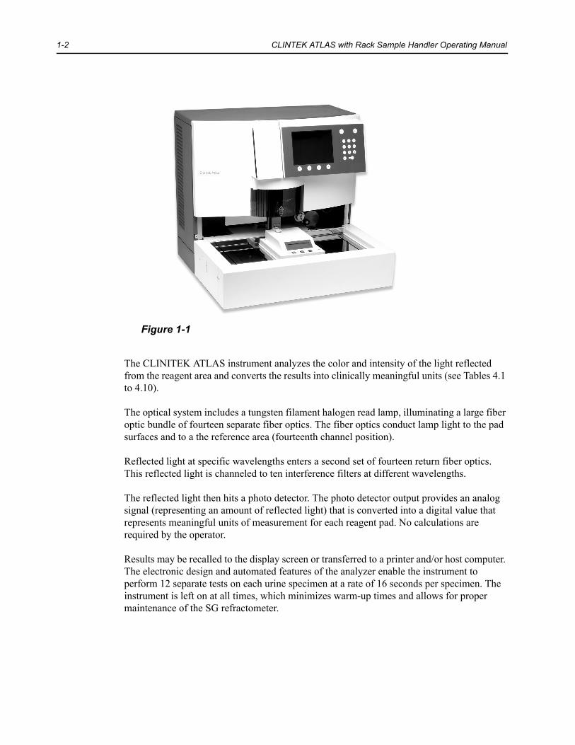
Figure 1-1
The CLINITEK ATLAS instrument analyzes the color and intensity of the light reflected from the reagent area and converts the results into clinically meaningful units (see Tables 4.1 to 4.10).
The optical system includes a tungsten filament halogen read lamp, illuminating a large fiber optic bundle of fourteen separate fiber optics. The fiber optics conduct lamp light to the pad surfaces and to a the reference area (fourteenth channel position).
Reflected light at specific wavelengths enters a second set of fourteen return fiber optics. This reflected light is channeled to ten interference filters at different wavelengths.
The reflected light then hits a photo detector. The photo detector output provides an analog signal (representing an amount of reflected light) that is converted into a digital value that represents meaningful units of measurement for each reagent pad. No calculations are required by the operator.
Results may be recalled to the display screen or transferred to a printer and/or host computer. The electronic design and automated features of the analyzer enable the instrument to perform 12 separate tests on each urine specimen at a rate of 16 seconds per specimen. The instrument is left on at all times, which minimizes warm-up times and allows for proper maintenance of the SG refractometer.

INTRODUCTION 1-3
The instrument is calibrated using four solutions found in the CLINITEK ATLAS Calibration Kit. A cleaning cycle and dry pad calibration are also performed as part of the Calibration Mode. At least 490 specimens, including calibrators and controls, can be tested with each reagent roll. Refer to your laboratory quality assurance program to ensure quality throughout the entire testing process.
Tubes containing samples to be tested are loaded into racks that each hold 10 tubes. Up to ten racks can be placed into the rack area on the right side (infeed). A minimum of two (2) mL of urine is required for testing.
This Operating Manual is designed to provide the user with the necessary information to operate and maintain the CLINITEK ATLAS System. The entire manual should be read before using the instrument. Pay special attention to Section 3 through Section 8.

1-4 CLINTEK ATLAS with Rack Sample Handler Operating Manual
Physical Characteristics
Control System—Analyzer
Figure 1-2
Communications between the operator and the instrument are made through the keyboard and the 12-line display. All instructions, menus, and messages are shown on the display, and the operator responds through the keyboard.
A screen saver will activate after 60 minutes of no activity on the keyboard. Press any key to return to the previous screen. (Version 7.11 or higher)
1 12-Line Display2 Soft Keys3 Keyboard

INTRODUCTION 1-5
The keyboard consists of ten numeric keys (0-9) plus three additional keys, whose functions are described below:
In addition to the 13 predefined keys, there are four “soft” keys along the bottom of the display. The function of these keys is defined by the specific screen being displayed. The specific key function is displayed immediately above the key. Not all of the softkeys are functional in every screen display.
Whenever an active keypad is pressed, a confirmatory key click sounds, unless this option has been turned off by the user. If an inactive keypad is pressed, a series of three short tones sounds.
Key Definition Description
BACKUP Returns the display to the previous (most recent) screen. If the cursor is in a data entry field, moves the cursor one position to the left and, in some cases, deletes that character. When the cursor is at the left-most position, restores the prior entry in the data entry field. If pressed again, exits the data entry field.
STANDBY Saves the data on the current screen, then returns the display to the Standby Mode (“Ready for Testing” screen).
ENTER Enters into memory the numeric information input or selects the menu option on which the cursor is located.

1-6 CLINTEK ATLAS with Rack Sample Handler Operating Manual
Control System—Rack Sample Handler
Figure 1-3
Communication between the operator and the Sample Handler is accomplished through the use of an LCD display and three LED keys located on the Sample Handler. During certain modes, each key lights up in a different color (green, yellow, or red) that corresponds to the function of the key. The key functions are also defined by the specific screen being displayed, in the same manner as the “soft” keys on the Analyzer display.
1 LED Keys2 LCD Display

INTRODUCTION 1-7
Sample Transport System
Figure 1-4
The platform of the Rack Sample Handler consists of two rack loading or unloading areas, the infeed on the right side and the outfeed on the left.
Racks can be loaded onto the right side only or onto both sides. Each rack is moved from front to back on the right side. It is then moved across the sampling area (right to left), then pushed from back to front on the left side. If the circulation function is selected, the racks continue to move across the front of the Rack Sample Handler (through the circulation area) from the left side to the right.
The racks are moved through the pushing action of sets of pawls, one on each side of the rack for forward/backward movement and a single one at the end the rack for side-to-side movement.
The STAT holder holds a single sample tube for processing in the STAT mode. It also holds the tube of bleach for performing the SG well cleaning cycle.
1 Sample Handler Outfeed2 Circulation Area3 STAT Holder4 Sampling Area5 Sample Handler Infeed

1-8 CLINTEK ATLAS with Rack Sample Handler Operating Manual
Pipetting System
Figure 1-5
The pipetting system consists of the syringe pump, pipette, and pipette transport.
For each sample:
1. The pipette moves to the appropriate tube on the sample tray and senses the sample level. The pipette will not detect non ionic solutions such as distilled or deionized water.
2. It then aspirates a small amount of the sample.
3. The pipette moves into position above the first reagent pad and dispenses a specific amount of sample onto each of the reagent strip pads and into the SG well for determination of the specific gravity and clarity.
4. It dispenses the remaining sample, followed by a larger volume of Rinse Solution, into the rinse well. This rinses both the inside and outside of the pipette.
5. Finally, the pipette dispenses the Rinse Solution into the SG well to ensure complete rinsing of the well.
1 Syringe Pump2 Pipette3 Pipette Transport

INTRODUCTION 1-9
Reagent Transport
Figure 1-6
The reagents, which are carried on a plastic backing, are transported from the reagent storage module through a series of sprockets. Each reagent strip is transported beneath the pipette, where a precise volume of urine sample is dispensed, then under the readhead assembly for reading. It then moves to the take up shaft where the backing is rolled around the shaft.
1 Reagent Storage Module2 Readhead Assembly3 Takeup Shaft

1-10 CLINTEK ATLAS with Rack Sample Handler Operating Manual
SG Refractometer/Clarity Device
Figure 1-7
Specific gravity is determined through the use of a fiber optic refractive index method. Light is transmitted through a specially shaped fiber optic onto which the sample is dispensed. The amount of light passing through the fiber optic is constantly measured at one end. The closer the sample’s refractive index is to that of the fiber optic, the more light is lost from the optic. Since refractive index is proportional to specific gravity, the light measured at the end of the fiber optic loop is linearly related to the specific gravity of the sample.
The refractive index of the Rinse Solution is determined between each sample as a reference value, compensating for temperature and light source variations. The clarity is also determined in this same area by measuring the transmission and scattering of light that passes through the specimen.
When samples are not being processed, the instrument dispenses a specific volume of Rinse Solution into the SG well every 15 minutes. This hydration step ensures that sample residues do not dry in the SG well and contaminate the fiber optic. Dried residue will influence the accuracy of subsequent SG readings until the well is cleaned. For this reason, the instrument must be left on at all times.
1 SG Well

INTRODUCTION 1-11
Rinse/Waste Systems
Figure 1-8
The instrument uses a Rinse Solution prepared by adding 2 mL of CLINITEK ATLAS Rinse Additive to 1000 mL of distilled or deionized water. The rinse bottle holds sufficient Rinse Solution for the use of one full reagent roll (490 tests).
The waste bottle is connected to the waste drain with tubing to allow easy access for emptying. It holds a sufficient volume of waste for the use of a full reagent roll.
The Rinse Solution tubing can be connected to a larger, non-pressurized container, and the waste tubing can be routed to an external drain.
1 Rinse Bottle2 Waste Bottle

1-12 CLINTEK ATLAS with Rack Sample Handler Operating Manual
Detection Systems
Figure 1-9
The instrument contains numerous different detection systems. Several are described below.
• Six different rack detectors determine the position of the racks in the Sample Handler. Figure 9-7 shows the locations of these sensors.
• The tube detector determines whether a tube is in place in a given position in the rack. If no tube is in place, the light from the detector is reflected back by a window on the back side of the STAT holder. A tube is detected when the light is interrupted by the tube and is not reflected back.
• The bubble sensor continually checks for fluid in the rinse tubing.
• The specimen level detector is located on the sample pipette. It determines the liquid level in each tube. This ensures that the pipette is submerged to a specific depth in the specimen.
1 Tube Detector2 Bubble Sensor
INTRODUCTION 1-13
Automated Bar Code Reader
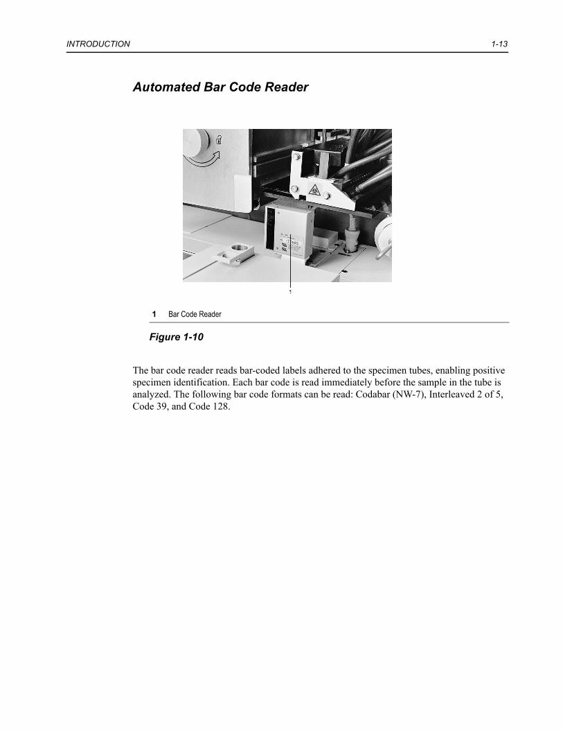
Figure 1-10
The bar code reader reads bar-coded labels adhered to the specimen tubes, enabling positive specimen identification. Each bar code is read immediately before the sample in the tube is analyzed. The following bar code formats can be read: Codabar (NW-7), Interleaved 2 of 5, Code 39, and Code 128.
1 Bar Code Reader

1-14 CLINTEK ATLAS with Rack Sample Handler Operating Manual
Rear of the Instrument
Figure 1-11
• The electrical power cord connects into the power receptacle.
• The instrument is turned on by pressing the top of the power switch.
• The instrument is cooled by a fan (located above the power receptacle).
• The fuse holder holds the fuses that protect the instrument against serious electrical overload.
• The interface connectors are the points at which a computer and/or 80-column or form printer can be connected.
The instrument contains two serial (EIA-232-D) ports. One (S1) can be used for interfacing to a host computer or LIS. The other port (S2) can be used for an optional handheld bar code scanner or alternate sample handlers, such as Lab Automation. The analyzer also contains one parallel (Centronics) port, to which most parallel printers can be interfaced.
1 Interface Connectors2 Power Receptacle3 Fuse Holder4 Power Switch

INTRODUCTION 1-15
Power Supply—Rack Sample Handler
Figure 1-12
The electrical power cord connects into the power receptacle. The power switch can be used to turn the Rack Sampler Handler on and off while the power to the Analyzer itself is turned off. Normally, however, this switch will be set to the OFF position, and power to the Rack Sample Handler will be controlled through the Analyzer.
1 Power Receptacle2 Power Switch

1-16 CLINTEK ATLAS with Rack Sample Handler Operating Manual
Optical System
A halogen lamp illuminates a large fiber optic bundle that is divided into 14 smaller bundles. One of the small bundles conducts the light from the lamp to a reference detector, where the amount of light is measured at all wavelengths. The remaining smaller bundles conduct the light to the reagent pad surfaces. A portion of the light striking the pad is reflected into a second set of fiber optic bundles. The wavelength of the reflected light depends on the degree of color change in the pad and is directly related to the concentration of the particular constituent in the urine.
The second set of fiber optic bundles conducts the reflected light to a disk that contains a set of interference filters. Under the instrument’s computer control, any filter in the disk can be positioned between any fiber optic and its corresponding photo detector. The light intensity that is reflected at one or more specific wavelengths from the surface of the reagent pad is converted by the photo detector into electrical impulses. These impulses are then processed by the instrument’s electronics, ratioed to the measurement of the reference detector at the same wavelength, and converted into clinically meaningful results.

INTRODUCTION 1-17
Specifications
Power required: Analyzer:120 VAC +10%/-15% 50/60 Hz
Optional—100 VAC +10% / -15% 50/60 Hz220–240 VAC +10% / -15% 50/60 Hz
Rack Sample Handler:100–240 VAC +10% / -15%, 50/60 Hz
NOTE: The CLINITEK ATLAS instrument has been manufactured and inspected as a 120 VAC instrument. Before it is used at any voltage other than 120 VAC, the instrument power cord, fuse, and/or rating label must be changed in order to comply with the specific requirements of each country.
Maximum Power Input: 600 VA (Analyzer)100 VA (Rack Sample Handler)
Heat Output: Approximately 2021 BTU/hour (Analyzer)Approximately 341 BTU/hour (Rack Sample Handler)
Dimensions: Depth — 64.8 cm (25.5 in.)Width — 72.4 cm (28.5 in.)Height — 66.0 cm (26.0 in.)
Weight: Instrument base only — 59.0 kg (130 lb.)Rack Sample Handler only — 27.5 kg (61 lb.)With sample handler attached — 86.5 kg (191 lb.)
Decibel Rating 60 dB (in a 20’ x 20’ room with no more than 40 dB background noise)
Recommended Minimum Bench Area:
Width — 78.7 cm (31 in.) (plus extra width on left for rinse bottle)Depth — 71.1 cm (28 in.)
Recommended Clearance Above Bench
71.1 cm (28 in.)
Ambient Operating Temperature Range:
18°C to 30°C (64°F to 86°F)

1-18 CLINTEK ATLAS with Rack Sample Handler Operating Manual
Ambient Operating Humidity Range:
20% to 80% relative humidity
Optimum Operating Conditions:
22°C to 26°C (72°F to 79°F)35% to 55% relative humidityNOTE: Because of the nature of some of the reagents found in the CLINITEK ATLAS Reagent Pak, reported values may be decreased at temperatures below 22°C (72°F) and increased at temperatures above 26°C (79°F).
Throughput: 16 seconds per specimen225 specimens per hour
Specimen Tube Requirements:
Style — LiplessWidth — 16 mmHeight — 95–104 mm
Calibration: Performed as a one or two point calibration, including baseline adjustment, for each reagent, clarity, and the SG refractometer to ensure optimal performance.
Compensation of Results: Leukocytes results are adjusted slightly to compensate for high specific gravity values (1.016 or above), unless “Japan (+/-)” is specified as the Result Units.
Performance of Specific Gravity Test:
Clinical studies have shown at least 90% of results to be within 0.005 of the TS Meter readings.
Linearity of SG Refractometer:
Results are linear through 1.045 when compared to the TS Meter. SG values up to 1.099 will be reported. However, measurements greater than 1.045 may be less accurate.
Limitation of SG Refractometer:
The presence of the drug Pyridium may interfere with the results obtained using the SG refractometer.
Performance of Clarity Test:
Clinical studies have shown good agreement between results obtained visually and instrumentally.
Limitation of Clarity Results:
Particulate material may settle out of the urine specimen prior to obtaining the instrumental clarity reading. Therefore, the clarity results obtained by the CLINITEK ATLAS may not show exact agreement with visual clarity readings that are obtained on freshly mixed specimens.

INTRODUCTION 1-19
ASTM Software Interface: Conforms to ASTM_E 1381-91, “Specification for Low-Level Protocol to Transfer Messages between clinical laboratory instrument and computer systems” and ASTM E 1394-91, “Specification for Transferring Information Between Clinical Instruments and Computer Systems.”
Instrument Safety Design: The instrument will operate safely in the following conditions:• indoor use only• installation category II (IEC 1010)• pollution degree 2 (IEC 1010)• maximum altitude 2000 meters (6560 feet)

1-20 CLINTEK ATLAS with Rack Sample Handler Operating Manual

2 INSTALLATION AND POWER UP
Installation
The CLINITEK ATLAS Automated Urine Chemistry Analyzer will be installed by your local technical support provider.
Environmental Factors
Prolonged exposure to excessive humidity and temperature should be avoided. Temperature should be held relatively constant to obtain the highest degree of operating stability.
The ambient temperature range for operating the instrument is 18°C to 30°C (64°F to 86°F). The optimum temperature range is 22°C to 26°C (72°F to 79°F). If the ambient room temperature changes by more than +5 °C from when the instrument was last calibrated, it should be recalibrated. At temperatures under 22°C, some results may be decreased, and at temperatures above 26°C, increased.
The ambient operating humidity range is 20% to 80% relative humidity. The optimum humidity range is 35% to 55% relative humidity.
Place the instrument where it will not be subjected to extreme temperature variations. Avoid proximity to direct sunlight, open windows, ovens, hot plates, open burners, radiators, and dry ice baths. It should also be located away from any instrument that uses a high voltage or large current, including centrifuges, large refrigerators and ovens. The instrument should not be used in an explosive atmosphere.
The bench on which the instrument is to be placed must have a firm, level surface, capable of supporting at least 90 kg (198 pounds) of weight. The surface should have a slope of no more than three degrees (3°) from horizontal in either direction.
Be sure the instrument will be located near a power source that meets the electrical requirements (voltage and amperage) specified on the rating label located on the rear panel of the instrument. The power receptacle must be grounded and should be a clean, noise-free, dedicated line.
CAUTIONThe CLINITEK ATLAS Analyzer is a precision instrument and must be handled accordingly. The instrument and the Rack Sample Handler are extremely heavy and therefore must always be moved by a minimum of two people. Rough handling of the instrument will disturb internal calibrated optics and electronics and/or cause other damage. Always handle the instrument with care.

2-2 CLINTEK ATLAS with Rack Sample Handler Operating Manual
Power-Up
Before turning the power on, close and latch both instrument doors if this has not been done previously (close the left door first).
Turn the power ON. The power switch is located on the rear of the instrument, immediately above the power cord (in the lower left corner when looking at the instrument from the front).
When the CLINITEK ATLAS instrument is first turned on, the fan will be heard. The screen will be blank for about 40 seconds while the operating software is loaded and memory tests are performed. After the 40 second delay, a series of screens will be displayed while the operating software is loaded and memory tests are performed. The initial screen will show the serial number of the Analyzer, and the revision of the software loaded. This information may be required by your local technical service provider.
During this time, the Sample Handler will also display the model number and software revision. After initialization, the Sample Handler will go to the Standby screen.
After power up, a stabilization and warming period of five minutes will be started, continually counting down on the display. During this time, testing and calibration cannot be performed. However, you can progress to the Main Menu and perform any of the options given on that menu during this waiting period. Press the keypad under the softkey option MAIN MENU to display this menu (see Section 3, MAIN MENU for a complete description of the Main Menu).
NOTE: If the instrument has been off for longer than one hour, prime the pump (by pressing 5 from the Main Menu). Then leave the instrument ON for at least one hour (to rehydrate the SG well) before re-assuming operation.
Once the five-minute warming period is complete, and if the Main Menu was not requested, the instrument will enter the Standby Mode. (If the instrument was running when power was lost, the analyzer will return to the screen that was active before power off.) If no operation occurs for ten minutes, the lamp will turn off. If the lamp is off for ten minutes, a 45 second warm-up will occur before operation can begin.
In Standby Mode, the Ready for Testing screen will be displayed. The following information is shown:
Field DefaultStrips remaining Not LoadedReagent Use Life Not LoadedReagent Pak Name Atlas 10Next Test Sequence #0-001Next Stat Sequence #S-001

INSTALLATION AND POWER UP 2-3
A variety of warning messages may also be displayed on the Ready for Testing screen. These warnings inform the user of the status of, for example, the reagents (not present, low quantity, expired use life), memory, and calibration. Because reagents have not yet been loaded into the newly installed instrument, “No Reagent” is displayed when the instrument is first turned on.
Three softkeys are also available from the Standby Mode:
ANALYZE: used to enter the Analyze Mode. Refer to Section 7, ROUTINE OPERATION, for information on this mode. If an error message is being displayed on the Ready for Testing screen, press ANALYZE to display further information on the error or warning.
STATUS: displays the STATUS screen, which provides information on the instrument’s memory and interface ports (see STATUS Display later in this section).
MAIN MENU: accesses the Main Menu, in the same manner as from the WARM-UP screen. For complete information, see Section 3, MAIN MENU.

2-4 CLINTEK ATLAS with Rack Sample Handler Operating Manual
STATUS Display
The STATUS Display can be requested from the Standby Mode (Ready for Testing screen). It provides information on the instrument’s memory and communication ports.
The display provides the following information:
Analyzer Memory Status: monitors and updates the status of the two memory locations. The instrument provides nonvolatile memory for 1000 routine and STAT results and for 200 control and calibrator results.
Routine/STAT Results: displays the status of the memory for routine and STAT results. If results are transferred to an external device (printer and/or computer), the number of results is constantly updated to reflect the remaining available space. If transmission is occurring properly, the available space is normally the same as or very close to the total space. If it is not, check for a communication problem (incompatible parameters, external device turned off, poor connection).If results are not transmitted to an external device (Computer and Printer Port Connections are set to OFF through the Connect to Computer and Connect to Printer menus in the Set Up Analyzer routine), the total and the available spaces are both 1000.Control/Calibration: displays the status of the memory for control and calibration results. If the QA Memory Status is set to ON, the status of this memory is monitored and updated each time a control or calibrator is analyzed. When the QA Report is printed, the available memory returns to 200. If the QA Memory Status is set to OFF, the total and the available spaces are both 200. See QA Memory Status‚ page 4-12 for details on setting QA memory status.
Analyzer Port Status: monitors and updates the status of the two communication ports (S1 and P1). The two ports are turned OFF or selected for use through the Set Up Analyzer menu, described in Section 4, CUSTOMIZING THE SOFTWARE. The Analyzer Port Status also displays the status of the S2 port.
S1 (Serial Port): displays the status of the first serial port. If the serial port is OFF, “Not Used” is displayed. If S1 has been selected for use, the status will show one of the following options, depending upon which Results Format was selected through the Set Up Analyzer menu (described in Section 4, CUSTOMIZING THE SOFTWARE):
• Computer/200+ mode (with the CT200+ format [CLINITEK® 200+ Urine Chemistry Analyzer]);
• Computer/ASTM mode (with the ASTM format); or• Computer/A2000 mode (with the CT A2000 format [CLINITEK Auto
2000 Automated Urine Chemistry Analyzer]).

INSTALLATION AND POWER UP 2-5
S2 (Serial Port): displays the status of the second serial port. If either the CLINITEK ATLAS handheld bar code scanner or an alternate sample handler is detected as connected to the S2 port, that device is identified (“Handheld BC Scanner” or “Sample Handler Interface”). Otherwise, the status is displayed as “Not Used.”P1 (Parallel Port): displays the status of the parallel port. The display will show either “Not Used” if the port is OFF or “Printer” if P1 has been selected for use.Status Options: provides the current status of the S1 and P1 ports if the port has been selected for use. With either port, the status options of “IDLE” or “ACTIVE” may be displayed. If an error has been detected through the interface, “ERROR” will be displayed. If a port is not configured for use (“Not Used”), the status option will be blank.
NOTE: If you have not already done so, press the MAIN MENU softkey to display the Main Menu options. It is through this menu that you will customize the CLINITEK ATLAS Analyzer to meet the individual needs of your laboratory, as instructed in Section 3 and Section 4.

2-6 CLINTEK ATLAS with Rack Sample Handler Operating Manual

3 MAIN MENU
The Main Menu on the Analyzer is displayed by pressing the keypad under the softkey option of MAIN MENU from the Standby Mode (Ready for Testing screen) and from the initial Warm-up screen after the instrument is turned on. The options available are:
1. Recall/Delete Results 2. Set Sequence Number3. Set Date/Time4. Load/Unload Reagent5. Prime Pump6. Clean SG Well7. Set Tone Volume8. Set Up Analyzer9. Analyzer Diagnostics

3-2 CLINTEK ATLAS with Rack Sample Handler Operating Manual
Recall/Delete Results
Results can be recalled to the screen for review or deleted from memory through this menu option. Refer to Section 8, RECALLING AND DELETING RESULTS, for complete instructions on using this option.
Set Sequence Number
Each specimen that is tested on the CLINITEK ATLAS Automated Urine Chemistry Analyzer is assigned a sequential identification number. The number is automatically incremented with each sample. The initial number can be selected through the Set Sequence Number menu option. Control and calibration samples have unique sets of sequential numbers that cannot be set by the user.
NOTE: The format of the sequence number is dependent upon the Results Format option that is currently active for the computer setup.
• The default condition (CT200+ format) uses a single-digit prefix number, plus a sequential number of three digits.
• The ASTM option uses a single-digit prefix plus a five-digit sequential number. • The CT A2000 option uses a four-digit number, with no prefix.
Refer to Section 4, CUSTOMIZING THE SOFTWARE, Analyzer Operation Menu, for an explanation of this option.
1. Press 2. Set Sequence Number from the Main Menu.
The Set Seq. Number screen will be displayed. The current sequence number is displayed and the cursor is positioned at the prefix (or first digit).
2. Use the numeric keypad to enter the prefix and sequential number.
If only the prefix needs to be changed, press after changing the prefix to accept the remainder of the number. All digits of the sequential number must be entered (e.g., “001”).
If an error is made when entering the number, press as needed to move the cursor to the left and correct the entry.
3. Press when the number has been correctly entered. The display returns to the Main Menu.
NOTE: When the sequence number reaches “999” (“99999” if the ASTM format is being used or “9999” with the CT A2000 format), the next number will be “001” (“00001” or “0001”). The prefix number does not change.

MAIN MENU 3-3
Set Date/Time
Press 3 from the Main Menu to display the Set Date/Time screen. Four different options can be selected through the use of softkeys located immediately below the display screen: Change Date Format, Change Date, Change Time Format and Change Time.
Change Date Format1. Press CHANGE DATE FORMAT from the softkey menu to change the formats. The date
can be displayed in one of three formats. The display will show the date in its current format, as well as the format description. A multiple choice menu lists the following format options:
• MM/DD/YYYY• DD.MM.YYYY• YYYY-MM-DD
2. Press the numeric key for your preferred format. The screen then returns to the Set Date/Time screen, with the date displayed in the new format.
NOTE: The date is always separated by hyphens (-) when it is transmitted to a host computer or LIS. The slash (/) and period (.) displayed with options 1 and 2 are not used.
Change Date1. Press CHANGE DATE from the softkey menu to change the date. The current date is
displayed, along with instructions to enter the date in the selected format.
2. Enter the correct date using the numeric keys. All digits must be entered, including leading zeros for numbers less than 10.
If an error is made in the entry, press the key as needed to move the cursor to the left, then enter the correct digit(s).
3. When the correct date has been entered, press . The screen reverts to the Set Date/Time screen.
Change Time Format
The time can be displayed in either 24-hour or 12-hour (AM/PM) format.
1. Press CHANGE TIME FORMAT from the softkey menu to change the time format.
The display will show the time in its current format, as well as the format description. The bottom line displays the format options.
2. Press the appropriate softkey for the preferred format (AM/PM or 24 Hour). The screen then returns to the Set Date/Time screen, with the time displayed in the new format.
3-4 CLINTEK ATLAS with Rack Sample Handler Operating Manual
Change Time1. Press CHANGE TIME from the softkey menu to change the time.
The current time is displayed, along with instructions to enter the time in the selected format.
2. Enter the correct time using the numeric keypad. The softkey(s) will disappear from the screen when the first numeric key is pressed and the instructions shown on the display will change to give added information.
If an error is made in the entry, press as needed to move the cursor to the left and correct the entry.
3. When the correct number has been entered, press . The softkey(s) will reappear.
4. Toggle the AM/PM softkey if necessary, then press DONE. The screen will revert to the Set Date/Time screen.
5. When all changes have been made from the Set Date/Time screen, press to return to the Main Menu.
Load/Unload Reagents
This menu option provides step-by-step instructions for loading and unloading the reagent roll. After completing the options provided in the Main Menu, refer to Section 5, LOADING THE REAGENT ROLL, for complete instructions.
Prime Pump
When the instrument is first installed, a priming cycle must be done before attempting to calibrate. Priming may also be necessary if the Rinse Solution bottle is allowed to become empty or is refilled at a time other than during the loading of a new reagent roll. Priming is also necessary if anything may have introduced air bubbles in the rinse line.
There may be other times at which the instrument requires the pump to be primed. However, if it is required because of the detection of an error, a softkey option will be displayed, making it unnecessary to return to the Main Menu to request the operation.
To prime the pump, press 5. Prime Pump from the Main Menu. The display will show the message “Please wait while the pump primes...”
The display returns to the Main Menu (or to the appropriate menu if the operation is selected from a softkey prompt) when the priming cycle is complete.
NOTE: If the instrument has been off for longer than one hour, prime the pump (by pressing 5 from the Main Menu). Then leave the instrument ON for at least one hour (to rehydrate the SG well) before re-assuming operation.

MAIN MENU 3-5
Clean SG Well
The SG well must be cleaned once a day or after loading a new reagent roll, whichever is more frequent. The procedure is performed automatically by the instrument and takes about 3 minutes.
• The display will prompt for SG well cleaning when 24 hours have elapsed since the last cleaning and again after a new reagent roll is loaded. The instrument will not begin processing until the cleaning procedure has been performed.
The cycle is started by pressing the softkey under the option CLEAN SG WELL that is displayed when the “Clean SG Well” warning is displayed.
• The SG well is also cleaned as part of the calibration procedure, regardless of whether calibration is requested through the Analyze Mode or is performed after a new reagent roll is loaded.
• In addition, the cleaning cycle can be requested at any time by pressing 6 from the Main Menu.
If the SG well needs to be cleaned at any time other than during calibration, the STAT holder must be used, as described in the following steps.
1. Press 6. Clean SG Well from the Main Menu or press the CLEAN SG WELL softkey.
2. Pour at least 2 mL of household bleach (5.25% sodium hypochlorite) into an appropriately labeled sample tube. This bleach solution is used to clean the SG well.
3. Pull the STAT holder forward (toward you) and place the tube of bleach into the holder. Push the holder back as far as it will go.
4. Press BEGIN on the Analyzer.
When the cleaning cycle is complete, the display returns to the Main Menu. Pull the STAT holder forward and remove the tube of bleach.
CAUTIONUse of bleach stronger than 5.25% sodium hypochlorite will damage the SG sensor. Therefore, check the concentration of sodium hypochlorite in the bleach being used. If it is higher than 5.25%, the bleach must be diluted with distilled water. For example, if the bleach is 6% sodium hypochlorite (e.g., Ultra Clorox), add 0.75 mL of water to 5 mL of the 6% bleach and mix gently.

3-6 CLINTEK ATLAS with Rack Sample Handler Operating Manual
Set Tone Volume
The volume of the instrument’s internal tone and the keyclick (the audible response when a keypad is pressed) can be changed through the use of this option.
1. Press 7. Set Tone Volume from the Main Menu.
2. Press the appropriate softkey for keyclick or volume. The active function will be designated by an arrow and the numeric keys can be pressed to increase or decrease the volume.
3. Press a numeric key (0-7) to set the volume of the instrument tone or the keyclick. The higher the number, the louder the volume. The bar graph shown will increase or decrease in response to each entry. As the key is pressed, a tone will sound at the new volume.
NOTE: The alarm that is sounded by the instrument to alert the operator to an error condition is not affected by any changes made through this screen.
4. Press when done to return to the previous screen, and set the second option.
5. When both have been properly set, press to return to the Main Menu.
Set Up Analyzer
Many of the operating functions of the CLINITEK ATLAS instrument can be customized through the Set Up Analyzer routine. The initial customization should be done after the instrument is installed. The parameters can then be modified as needed.
The Set Up Analyzer routine is entered by selecting 8 from the Main Menu. Correct entry of the password is required in order to access the routine. See Section 4, CUSTOMIZING THE SOFTWARE, for a complete description of this routine.
Analyzer Diagnostics
The Analyzer Diagnostics routine provides access to the following functions:
• It allows the user to perform several repair functions and minor adjustments. • It allows the display of several aspects of the raw data. This can help your local
technical service provider when attempting to troubleshoot an instrument problem. • The default values that are in place upon initial installation (Set Up Analyzer
Routine) can be restored. • The password can be changed.
Correct entry of the password is required in order to access the Analyzer Diagnostics routine. See Section 11, ANALYZER DIAGNOSTICS, for complete information on this routine.

MAIN MENU 3-7
Softkey Options
If the instrument has been configured for use with a printer and the P1 port selected for use (Connect to Printer Menu‚ page 4-41), there are two softkey options that are available from the Main Menu:
• Print QA Report• Print Setup
NOTE: Neither of the softkey options (PRINT QA REPORT and PRINT SETUP) will be displayed if the Printer Paper Type has been selected as “Vertical.” See Section 4, Paper Type‚ page 4-42.
Print QA Report
When control and calibration specimens are analyzed on the CLINITEK ATLAS instrument, they are assigned a special prefix and sequential number. The prefix depends upon the selection made for the Results Format (through the Set Up Analyzer routine).
• If the CT200+ or ASTM format is selected, the prefixes are “C” for controls and “K” for calibrators.
• If the CT A2000 format is selected, the prefixes are “CN” and “KL.”
The results are then stored in a unique memory area that is separate from that used for routine and STAT analyses. Up to 200 control and calibration results are stored in this memory.
Because the CT A2000 format uses only 2 digits for the sequential number, the numbers will duplicate. However, records can be differentiated by the date on which the calibrator or control was assayed.
Press the PRINT QA REPORT softkey option on the Main Menu to print control and calibrator records. The instrument must be configured to use an 80-column printer and the printer must be connected to the instrument.
It is suggested that a printout of the control and calibrator results be obtained on a regular basis (e.g., weekly or monthly).

3-8 CLINTEK ATLAS with Rack Sample Handler Operating Manual
NOTE: • If QA Memory Status is set to ON (see QA Memory Status‚ page 4-12), only those
records that have not been previously printed will be printed when this softkey is pressed.
After printing, you will be prompted to confirm that the report did print. It can be reprinted if necessary. Once the report has been printed and confirmed, the records are flagged and become available to be overwritten. The flagged control records can be reprinted only through Recall Results (see Section 8, RECALLING AND DELETING RESULTS). Calibration records cannot be reprinted.
• If QA Memory Status is OFF, all records in memory are printed each time this softkey is pressed.
Print Setup
It is strongly recommended that a printout of the instrument setup configurations be obtained after all parameters have been selected through the Set Up Analyzer routine (see Section 4.)
This can be done by pressing the softkey under PRINT SETUP on the Main Menu. The instrument must be configured for use with an 80-column printer and the printer connected to the instrument before selecting this option.

4 CUSTOMIZING THE SOFTWARE
General Information
The software in both the CLINITEK ATLAS Analyzer and the Rack Sample Handler can be customized to fit your individual laboratory requirements. Customization of the Analyzer and Sample Handler is described separately in this section. Customize the Sample Handler first, as described below.
User Setup Mode—Sample Handler
Customization of the Rack Sample Handler is selected through the User Setup Mode, which is accessed at the Rack Sample Handler Control System (LCD and LED keys on Rack Handler.
First enter the Menu Mode by pressing the key beneath the word Menu on the Standby screen of the Sample Handler. Each time the Menu key is pressed, a different selection or option is displayed on the top line of the display. The bottom line displays up to three “soft keys” that change with each Menu screen. These key options correspond to the three colored keys located immediately beneath the display.
Press the Menu key repeatedly until the User Setup screen is displayed.
Most option screens in the User Setup Mode show the same three softkeys:
ESC: Returns the display to the User Setup screen
ENT: Selects the displayed option for further definition
Menu: Changes to the next menu option in the User Setup Mode
Once an option has been selected by pressing ENT, one or more additional screens are displayed that allow you to customize the option. The current selection is either displayed on the top line or is preceded by an asterisk (*). Where appropriate, the default setting is noted in the text below.

4-2 CLINTEK ATLAS with Rack Sample Handler Operating Manual
Rack Circulation
Set Rack Circulation ON/OFF
The first screen displayed when ENT is pressed from the User Setup screen is the Rack Circulation screen, which allows the operator to select whether rack circulation is to occur.
1. Press ENT from the Rack Circulation screen to select an option.
2. On the next screen, press the appropriate key to turn rack circulation ON or OFF:
• If OFF (the default) is selected, the racks move from the right side (infeed) to the left side (outfeed) only. After a maximum of 10 racks have been processed, the run ends.
• If ON is selected, racks can be loaded onto both the right and left sides. As the racks move from the right side through the sampling area to the left side, racks from the left side are moved across the front of the Sample Handler to the right side, where they can then be processed.
3. Press CONT after making your selection.
• If OFF was selected, the display returns to the Rack Circulation screen. Press Menu to set the next option.
• If ON was selected, the Circulation Stop By screen is displayed.
Set Circulation Stop By1. Press the appropriate key from the Circulation Stop By screen to select the method by
which circulation ends:
• If 20Rack (the default) is selected, the number of racks will be counted before circulation begins, and circulation will stop after a maximum of 20 racks have been processed (10 racks placed onto the right side and 10 onto the left side).
• If Marker is selected, circulation will continue until the Stop Marker is detected. This special marker is placed in the final rack to be processed, after the last specimen. This feature allows additional racks to be added during a run.
It is the operator’s responsibility to ensure that the Stop Marker is in place, or that racks are removed after they have been processed. Otherwise, processed racks will continue to circulate, and specimens will be tested again.NOTE: Testing will also stop if the system detects 10 consecutive empty tube positions.
2. Press CONT. The display returns to the Rack Circulation screen.
3. Press Menu to set the next option.
CUSTOMIZING THE SOFTWARE 4-3
Bar Code Reader
Set BC Reader ON/OFF
Use of the bar code reader is specified through the Barcode Reader screen.
1. Press ENT from the Barcode Reader screen to select the use of the bar code reader and to customize the reader for your bar-coded labels.
2. Press the appropriate key to turn the use of the bar code reader ON or OFF, then press CONT.
• If OFF (the default) is selected, the display returns to the Barcode Reader screen. Press Menu to set the next option.
• If ON is selected, additional options must be selected, beginning with the bar code type.
Set Bar Code Type
Through the Barcode Type screen, the bar code reader can be programmed to read a specific bar code format or to automatically determine and read the format presented. Four formats can be read:
• Codabar (NW-7)• Code 39 • Interleaved 2 of 5 (I-2of5)• Code 128
1. Press the Up or Down key to cycle through the list of options: Auto, NW-7, CODE39, I-2of5, CODE128. Pressing Down reverses the order. The default setting is Auto.
2. Select the appropriate format, or Auto. Then press CONT.
NOTE: If a single format of bar code is used, that format should be selected. This will provide faster and more consistent readings. The Auto selection should be selected only if more than one format is used.
Set STAT Bar Code Reader ON/OFF
The STAT bar code reader option is only supported in Japan. It is an external hand-held reader for the STAT tube only (not the STAT rack), which is connected to Port CN-103 (on the left side of the Rack Sample Handler). The default setting for the STAT reader is OFF.

4-4 CLINTEK ATLAS with Rack Sample Handler Operating Manual
Remove Leading/Trailing BC Characters
The CLINITEK ATLAS Analyzer can display, store, and transmit a maximum of 13 characters. All characters in excess of this are ignored when the bar code is read. Through this option, up to nine leading or trailing bar code characters can be removed (chosen as the characters to ignore). The default setting is to remove zero characters.
1. In the Remove Lead BC Char screen, press the Up or Down key as needed to display the number of leading characters (0 to 9) to be removed. Then press CONT.
2. In the Remove Trail BC Char screen, press the Up or Down key as needed to display the number of trailing characters (0 to 9) to be removed. Then press CONT.
Test Bar Code Labels
The Barcode Test screen allows you to test bar-coded labels in the same manner as would occur with routine specimens.
1. Label one or more specimen tubes with bar-coded labels of the format and quality you will be using.
NOTE: The bar code lines must be perpendicular to the length of the tube (a skew of greater than 5° may result in reading problems). Refer to Section 14, BAR CODE Reader for additional information.
2. Place the bar-coded tubes into a specimen rack, with the label facing the open side of the rack.
3. Load the rack onto the right side of the instrument, with the open side facing to the back.
4. Press ENT. The light on the bar code reader will begin to blink on and off.
5. Gently push the rack forward and then to the left through the sampling area, slowly passing the first tube in front of the bar code reader. The label will be scanned and the result displayed on the Sample Handler screen.
6. Record the displayed number to compare to the intended number.
7. The letters “NG” (No Good) will be displayed on the top line if:
• the bar code cannot be read;• the bar code format is not the same as was selected through the Bar Code Type
screen (See Set Bar Code Type‚ page 4-3); or• the bar code being displayed has more than 13 characters, including the start and stop
characters.NOTE: If the number of “NG” errors encountered equals the barcode error limit (see Set Bar Code Error Limit‚ page 4-5), the ATLAS will stop processing samples during a run.
8. Repeat the process for each labeled tube, then press STOP when finished to turn the bar code reader off. The display returns to the Bar Code Reader screen.
9. Compare the number displayed during the test to the number on the tube.
CUSTOMIZING THE SOFTWARE 4-5
10. Use this information to determine whether any leading or trailing characters need to be removed (for example, if a checksum is being displayed). Remember that only 13 characters can be transmitted to the Analyzer and excess characters should be removed.
11. Press Menu to continue to the next option.
NOTE: If the use of a bar code reader has been selected as OFF, the next option is not displayed and the screens continue as shown in Rack Number Reset‚ page 4-6.
Bar Code Errors
Set Handling of Samples with a Bar Code Error
If an error is detected when reading a bar-coded label, the specimen can be either tested or skipped.
1. Press ENT from the Barcode Error screen to specify how bar code errors are to be handled.
2. From the Barcode Error Sample screen, press the appropriate key to specify an action:
• If Test (the default) is pressed, the specimen will be tested and the results stored without an ID number. The ID can then be entered during the End of Run Review.
• If Skip is pressed, the tube will be skipped and the specimen not tested at all.
With either action, the position number of the specimen for which there is a bar code error will be stored and displayed at the end of the run.
3. Press CONT when the selection has been made to advance to the Barcode Error Limit screen.
Set Bar Code Error Limit
After a specific number of bar code errors have been recorded, the Sample Handler stops processing. The number of errors that will be recorded before the run is stopped is selected from the Barcode Error Limit screen.
1. From the Barcode Error Limit screen, change the current selection by pressing the Up and Down keys as needed. The limit can range from 0 to 20. If 0 is selected, there is no limit to the number of errors that can accumulate. The default setting is three.
2. Press CONT when finished.
NOTE: When the error limit is reached, the run ends immediately. The specimen in the tube that produced the final error is not tested.

4-6 CLINTEK ATLAS with Rack Sample Handler Operating Manual
Set Bar Code Error Alarm
In the next screen, an alarm can be set, to sound each time a bar code error is detected.
1. From the Barcode Error Alarm Screen, press the appropriate key to turn the alarm ON or OFF (the default).
2. Press CONT to advance to the Error Alarm screen.
3. If ON was selected in Step 1, the Error Alarm screen allows you to select how often the alarm will sound.
Press the appropriate key to select an action:
• If ALWAYS is pressed, the alarm will sound with each tube once the first error has occurred.
• If ONCE (the default) is pressed, the alarm will sound only when an error actually occurs.
4. Press CONT when your selection has been made. The screen returns to the Barcode Error screen.
5. Press Menu to continue to the Rack No. Reset screen.
Rack Number Reset1. Press ENT from the Rack No. Reset screen to specify how the rack number will be reset
to 1.
2. Press the appropriate key, then press CONT when your selection has been made:
• If Key (the default) is pressed, you will be prompted as part of the Menu Mode to reset the rack number. The rack counter will continue to increment (from 1 to 999, then back to 1) until the number is reset through the Rack No. screen (see Menu Mode - Sample Handler‚ page 7-3).
• If RUN is pressed, the rack number resets to 1 each time a new run is started.NOTE: Anytime power is lost to the Sample Handler, the rack sequence number will be reset to 1.
3. Press Menu to continue to the Pipette Height screen.
Pipette Height
The pipette height determines the maximum distance the pipette will descend into a specimen tube. The default setting of 70 mm requires a minimum sample volume of approximately 8 to 10 mL, depending on the style of specimen tube.
Pipette height is set during installation. If you require a different pipette height setting, please call your local technical service provider.
CUSTOMIZING THE SOFTWARE 4-7
Review Setup Parameters
The final screen in the User Setup Mode allows the operator to review the selections that have been made.
1. Once all parameters have been set, press Menu to go to the Review Setup Parameter Screen.
2. Press ENT from the Review Setup Parameter screen and the name and status of the first parameter in the mode is displayed.
3. Press CONT to display the next parameter. When the final option has been displayed, the screen returns to the Review Setup Parameter screen.
Press ESC at any time during the Review Setup screens to immediately return to the Review Setup Parameter screen.
4. Press Menu to return to the User Setup screen.
5. If any changes need to be made to the User Setup parameters, press ENT from the User Setup screen, then press Menu until the parameter is reached.
6. When all selections have been made, press either Menu or ESC from the User Setup screen to return to the Standby screen.

4-8 CLINTEK ATLAS with Rack Sample Handler Operating Manual
Set Up Analyzer Routine - Instrument
The software in the CLINITEK ATLAS Automated Urine Chemistry Analyzer can be customized to fit your individual laboratory requirements. The software is customized through the Set Up Analyzer routine at the instrument display.
To enter the Set Up Analyzer Routine, select 8. Set Up Analyzer from the Main Menu. A password (numeric code) is required in order to access this routine. Enter the password at the bottom of the screen.
The default password is 2633. A different password can be selected through the Analyzer Diagnostics routine; however, the default code is always active. The same password is used to access the Analyzer Diagnostics routine.
Enter the password by pressing the appropriate numeric keys (asterisks will be displayed on the screen). Then press .
If the password does not match either the customized password or the instrument default password, the display prompts the user to re-enter the password.
When an acceptable code is entered, the Set Up Analyzer menu is displayed. The options available are:
1. Analyzer Operation2. Specimen Information3. Analyte Information4. Connect to Computer5. Connect to Printer6. Language
Each menu option is explained in detail in this section. Initial customization is most conveniently done by following the order given in this section, selecting each menu item in order.
NOTE: The default language for the analyzer screen displays is English. Other available languages are Japanese, Italian, Spanish, or German. Select the language first, before performing any other customization.The language is selected by pressing 6. Language from the Set Up Analyzer menu and pressing the softkey for the language. See Language‚ page 4-45, for more information. The language selection affects only the Analyzer display. The screens on the Rack Sample Han-dler are displayed in English only.

CUSTOMIZING THE SOFTWARE 4-9
Analyzer Operation Menu
Press 1 from the Set Up Analyzer menu to customize the following aspects of analyzer operation.
Options 2 (Sample Tray Type) and 5 (Waste Bottle) are not accessible when using the Rack Sample Handler. The default, or currently active, selections are displayed. Press the appropriate numeric key to change the current selection on a parameter. The display will change to show the possible options for that parameter. Trying to select an option that is not available (no number is displayed) will cause an inactive tone to sound.
Reagent Pak Name
A new function has been added to the Atlas to provide future capability. The first option on the Set Up Analyzer Menu will be used for this purpose. At this time, please leave this selection as the default (Atlas 10).
Sample Tray Type
This option is not available when using the Rack Sample Handler. (Pressing 2 will cause an inactive tone to sound.)
Results Format
The CLINITEK ATLAS instrument can be customized to simulate two reporting modes currently used by other CLINITEK instruments, the CLINITEK 200+ Urine Chemistry Analyzer or the CLINITEK Auto 2000 Automated Urine Chemistry Analyzer.
Menu Option Default1. Reagent Pack Name Atlas 102. Sample Tray Type N/A3. Results Format CT200+4. Result Units English-Conv5. Waste Bottle External6. STAT Reset Time 12:00 AM7. QA Memory Status OFF8. Auto. Run After Cal. OFF9. End of Run Review ON

4-10 CLINTEK ATLAS with Rack Sample Handler Operating Manual
If you have a software interface program that can transfer results from either of these two instruments to a host computer or LIS (Laboratory Information System), the CLINITEK ATLAS instrument can be configured to send its results in a nearly identical format. Refer to Tables 4.1 to 4.10 for the reported values available in each of these formats.
The instrument can also be customized to transmit results in the ASTM (American Society of Testing and Materials) protocol. This is a standardized software interface for laboratory computers and instruments. Refer to Tables 4.1 to 4.8 for the reported values available in this format.
1. If the “CT A2000” format is selected (to emulate the CLINITEK Auto 2000 instrument), several options are not available. Specimen IDs, color, clarity, and “abnormal” flags cannot be transmitted through the serial port (to the host computer or LIS). These options are available on the displayed and printed report only. Press 3. Result Format from the Analyzer Operation menu to select the format for communication between the CLINITEK ATLAS instrument and the computer. The options are:
• ASTM• CT200+• CT A2000
2. Press the softkey for the appropriate results format. (CT200+ is an abbreviation for CLINITEK 200+ Analyzer, and CT A2000 for CLINITEK Auto 2000 Analyzer.) The display returns to the Analyzer Operation menu.
Some of the host computers or LIS use software interface programs with the CLINITEK 200+ or CLINITEK Auto 2000 instrument that are data sensitive. That is, they expect specific values for each analyte. They may also expect the analytes to be reported in a specific order.
Using SG as an example, the CLINITEK 200+ instrument reports SG values in 0.005 increments (<=1.005, 1.010, 1.015, etc.). If these are the only values your interface program will accept (it would reject a value of 1.008 or 1.021), the program is probably data sensitive. If so, you must not change the default values that are programmed for the format selected. Otherwise, you must modify your interface program in order to transmit data from the CLINITEK ATLAS Analyzer.
It is suggested that you obtain a printout of the setup options for your CLINITEK 200+ instrument, or determine the switch settings being used with your CLINITEK Auto 2000 Analyzer. These same settings should be used when customizing the CLINITEK ATLAS instrument.
If your interface program is not data sensitive (it accepts any value that conforms to the specified number of characters), many of the default settings can be changed to provide greater flexibility in the reporting of results.

CUSTOMIZING THE SOFTWARE 4-11
Result Units
The test name abbreviations and the units in which the results are displayed are dependent upon the language or country that is selected. The options that are available depend upon the selection made for the Results Format.
• If CT200+ or ASTM is selected, results can be displayed in several different languages and units.
• If CT A2000 is selected, the units are selected by country, but all results are displayed in English.
1. Press 4. Result Units from the Analyzer Operation menu to select result units.
If CT200+ or ASTM is the Results Format selection, the display lists the options as:
If the Results Format selection is CT A2000, the display shows the following softkey options:
• Italy• Japan• Spain• USARefer to Tables 4.1 through 4.10 for the test name abbreviations and options for display of the results for each of the language/country options.
2. Press the appropriate numeric key for the language/units or the appropriate softkey for the country. The display will return to the Analyzer Operation menu.
Waste Bottle
The waste drain must be connected to the external tubing when using the Rack Sample Handler. Therefore, this option defaults to External and is not available for selection.
NOTE: The display will not prompt to empty the waste bottle when this option is set to External. Therefore, be sure to check the waste bottle periodically (if being used) and empty it when necessary.
• English (Conv)• English (SI)• French (Conv)• Italian
• Japan (+/-)• Spanish• German (Conv)• German (SI)

4-12 CLINTEK ATLAS with Rack Sample Handler Operating Manual
STAT Reset Time
Depending on which Results Format is selected, STAT specimens are assigned a sequential number from a unique series that has an “S” or “ST”.
• The “S” prefix indicates CT200+/AST.• The “ST” prefix indicates CT A2000.
The numbers are reset every 24 hours to “S-001” (CT200+), “S-00001” (ASTM), or “ST01” (CT A2000).
The time at which the numbers are reset can be customized to fit your individual laboratory’s work flow.
1. Press 6. STAT Reset Time from the Analyzer Operation menu to change the reset time.
2. Enter the time using the numeric keypad.
The softkey(s) will disappear from the screen when the first numeric key is pressed and the instructions shown on the display will change to give added information.
Use the numeric keypad to enter the time. Press if there has been an error.
3. When the correct number has been entered, press . The softkey(s) will reappear.
4. Toggle the AM/PM softkey if necessary, then press DONE. The display returns to the Analyzer Operation menu.
QA Memory Status
Control and calibration results (with prefixes of “C” or “CN” and “K” or “KL”, respectively, and depending on the Results Format selected) are stored in a separate memory from that used to store patient results. Two hundred sets of results are stored. See Print QA Report‚ page 3-7 for detailed explanations of result prefixes.
When the memory is filled (200 results), no further calibration or control testing will be allowed until the results are printed, or new results will immediately overwrite the oldest results. This option is set through the QA Memory Status screen.
1. Press 7. QA Memory Status from the Analyzer Operation menu to select an option:
• If the QA Memory Status is set to ON and the memory is full, stored results must be printed before additional control or calibration testing can occur. Once stored results are printed, records are flagged and can be overwritten.
If a control record has been flagged (already printed), it can still be reviewed and printed through Results Recall until it is overwritten (see Section 8). A warning is displayed when the number of unflagged stored sets reaches 190.
• If the QA Memory Status is set to OFF and the memory is full, each new set of control or calibration results overwrites the oldest set stored in memory.
CUSTOMIZING THE SOFTWARE 4-13
Each time the QA Report is printed, all records in memory (up to the memory capacity of 200) will be printed.
2. Press the appropriate softkey for the option (ON or OFF). The display then returns to the Analyzer Operation menu.
NOTE: The QA Memory Status and the Printer Paper Type (see Connect to Printer Menu‚ page 4-41) are mutually exclusive.
• If QA Memory is ON, the Vertical Paper Type is not available for selection. • If the Vertical Paper Type has been selected, QA Memory Status cannot be selected
as ON. This is because the QA Report cannot be printed onto a vertical paper type. If you want to select QA Memory as ON (and the option is not accessible), you must first change the paper type to 80-Column.

4-14 CLINTEK ATLAS with Rack Sample Handler Operating Manual
Auto. Run After Cal.
The instrument can be configured to automatically enter the ROUTINE Analyze Mode immediately following calibration.
If calibration is successful, the instrument will automatically begin analyzing the specimens that are found in any additional racks that are loaded into the right side of the Sample Handler. If no racks are found, the instrument will return to the Standby Mode after calibration has been completed.
1. Press 8. Auto. Run After Cal. from the Analyzer Operation menu to select this option.
2. Press the appropriate softkey to select either OFF or ON. The display will then to the Analyzer Operation menu.
End of Run Review
The End of Run Review alerts the operator to the presence of one or more specimens for which there are no results or for which there is missing information (such as ID number). The missing information can be entered using the handheld bar code scanner and/or the keyboard.
Specimens meeting the criteria for the sieve search will also be listed so the tubes can be pulled for further testing. See Define Sieves‚ page 4-33 for details.
• If the End of Run Review option is set to ON, the review occurs at the end of each run, when necessary.
• If the option is set to OFF, the display returns to Standby (Ready for Testing screen) after each run.
1. Press 9. End of Run Review from the Analyzer Operation menu to select this option.
2. Press the appropriate softkey to select either OFF or ON. The display then returns to the Analyzer Operation menu.
NOTE: The End of Run Review and several options on the Specimen Information Menu (see Specimen Information Menu next) are mutually exclusive.
• If End of Run Review is OFF, the Specimen ID Source cannot be through the Keyboard, and Color Determined By and Clarity Determined By must be through the Analyzer. This is because there will be no opportunity to manually enter the ID, color, or clarity into the record.
• If the Specimen ID Source is selected as Keyboard and/or color or clarity determination is selected as Visual, the End of Run Review must be ON.
Therefore, if you want to select the End of Run Review as OFF (and the option is not acces-sible), you must first change the Specimen ID Source to something other than Keyboard and Color/Clarity Determined By to Analyzer. Refer to Specimen ID Source, Color Determined By, and Clarity Determined By later in this section for further information.

CUSTOMIZING THE SOFTWARE 4-15
Return to the Setup Analyzer Menu
When all Analyzer Operation options have been selected, press to return to the Set Up Analyzer menu
NOTE: If changes have been made to the Results Format‚ page 4-9 or Result Units‚ page 4-11, a warning screen may be displayed when you attempt to exit from the Set Up Analyzer menu. Refer to Operating Note‚ page 4-45 for further information on the possible warnings.
Specimen Information Menu
Several options relating to specimen identification and descriptions can be customized through the Specimen Information menu. Press 2 from the Set Up Analyzer menu to customize the following aspects of analyzer operation.
Option 2 (Load List Deletion) is not accessible when using the Rack Sample Handler. If the Results Format selected previously is CT A2000, options 3 (Record Urine Color) and 7 (Record Urine Clarity) are available for use in the displayed and printed reports only. They cannot be sent from the serial port to the LIS or host computer.
The default, or currently active, selections are displayed. To change the current selection on a parameter, press the appropriate numeric key and the display will change to show the possible options for that parameter.
Menu Option Default1. Specimen ID Source OFF (if the bar code reader is on, the
ID source is Sample H.)2. Load List Deletion N/A3. Record Urine Color ON4. Color Determined By Analyzer5. Select Colors See below for default information.6. Set Color Normal Range See below for default information.7. Record Urine Clarity ON8. Clarity Determined By Analyzer9. Adjust Clarity Ranges No Clarity Adjustment (0%)

4-16 CLINTEK ATLAS with Rack Sample Handler Operating Manual
Specimen ID Source
Identification numbers that are unique to the specimen or to the patient can be entered into the record of each specimen tested. This option allows you to specify whether ID numbers will be used and, if used, their source. The numbers can be entered into the CLINITEK ATLAS memory from the Rack Sample Handler’s bar code reader or entered at the end of the run, using the handheld bar code scanner or through the instrument keyboard.
1. Press 1. Specimen ID Source from the Specimen Info. menu. The following options are provided:
• Off (Specimen IDs are not used)• Load List (Sent from computer)• Sample Handler• Keyboard (Data entered at end of a run)
Load lists are not allowed with the Rack Sample Handler. Therefore, option 2 (Load List) is not accessible.
2. Press the appropriate numeric key for the preferred selection. If you do not want to use ID numbers at all, press 1 for OFF. If OFF or Keyboard is selected, the display returns to the Specimen Info. menu.
• If Sample Handler is selected as the ID Source, the bar code reader must be set up through the User Setup Mode on the Rack Sample Handler, as described at the beginning of this section. During the run, each bar-coded tube is read and the number entered into memory as the ID# specific to that specimen. If a bar code cannot be read during a run, the ID# can be entered during the End of Run Review, if End of Run Review is set to ON. If the format of the bar code labels in use is unknown, see the Set Bar Code Type‚ page 4-3 and Test Bar Code Labels‚ page 4-4 for information on determining bar code type.
• Keyboard entry of the Specimen ID and End of Run Review (see End of Run Review‚ page 4-14) are mutually exclusive. If End of Run Review was selected as OFF, there will be no opportunity to manually enter the specimen ID into the record. Therefore, Keyboard is not accessible. If you want to use keyboard entry of ID numbers, you must first change the End of Run Review to ON.

CUSTOMIZING THE SOFTWARE 4-17
Set Up Optional Handheld Bar Code Scanner (North America)
If Sample Handler is selected as the Specimen ID Source, and if a CLINITEK ATLAS handheld bar code scanner is detected as being connected to the S2 port, a softkey option of “SET UP BC SCANNER” is displayed.
NOTE: End of Run Review must be selected in order to enter bar code information using the handheld bar code scanner.
1. Press this key to change the display to allow entry of the appropriate parameters for using the handheld scanner. Before setting up the handheld scanner, it must be installed and bar-coded identification labels available for use on the specimen tubes. The default, or currently active, selections are displayed:
The parameters selected for the handheld scanner must be consistent with those previously selected for the bar code reader on the Rack Sample Handler (User Setup Mode—Sample Handler‚ page 4-1).
2. To select the appropriate parameters, press the appropriate numeric key.
LASER WARNING: The handheld bar code scanner emits a low-power visible laser. To avoid damage to the eyes, never look directly at the laser beam or at its reflection from a shiny surface. Also, never point the scanner at anyone. Only trained field service personnel should perform procedures related to laser assemblies.Refer to Appendix D, Laser Safety for more safety information and laser specifications.
Menu Option Default1. Bar Code Type AUTO DET2. Remove Lead BC Char. 03. Remove Trail BC Char. 04. Test Bar Code Label

4-18 CLINTEK ATLAS with Rack Sample Handler Operating Manual
Bar Code Type
The format of the bar code being used must be selected through the Bar Code Type screen.
NOTE: With newer scanners, you cannot adjust the bar code type. The format is set to AUTO DET and cannot be altered.
1. Press 1. Bar Code Type.
2. Press the appropriate numeric key to specify the bar code format. The bar code formats that can be selected are:
• Auto Detect• Codabar (NW-7)• Code 39• Interleaved 2 of 5 (I-2of5)• Code 128Press Auto Detect only if more than one format is used. Faster and more consistent readings will occur if the specific format being used is selected. The display will then return to the previous menu.
Remove Lead BC Char.
Leading characters in the bar codes read by the handheld scanner can be automatically removed (ignored), in the same manner as with the bar code reader on the Rack Sample Handler. However, the number of characters that need to be removed may be different from what is needed with the bar code reader on the Sample Handler (see Test Bar Code Label‚ page 4-19).
1. To change the number of characters removed, press 2. Remove Lead BC Char from the Set Up Handheld BCS menu.
2. Enter the number of leading characters to be ignored in the ID number.
3. When the correct number has been entered, press and the display will return to the Set Up Handheld BCS menu.
Remove Trail BC Char
As with Remove Lead BC Char., trailing characters can also be automatically removed (ignored).
1. To change the number of characters removed, press 3. Remove Trail BC Char. from the Set Up Handheld BCS menu:
2. Enter the number of trailing characters to be ignored in the ID number.
3. When the correct number has been entered, press and the display will return to the Set Up Handheld BCS menu.

CUSTOMIZING THE SOFTWARE 4-19
Test Bar Code Label
Bar-coded labels can be tested to ensure that the correct format has been selected and that the labels can be read using the handheld scanner.
1. Press 4. Test Bar Code Label from the Set Up Handheld BCS menu.
The format selected previously is shown on the display.
2. Label one or more specimen tubes with bar-coded labels of the format and quality you will be using.
3. Scan the labels using the handheld scanner (refer to Operating the Handheld Bar Code Scanner which accompanied the scanner for information on its use).
4. Each time a bar code is read, the number will be displayed on the screen.
5. Check that the number agrees with the intended number. If a number is not displayed, check pwer connections and data connections to the handheld bar code scanner. Also, make sure End of Run Review is set to ON.
6. Press to return to the Set Up Handheld BCS menu.
NOTE: The Test Bar Code Label feature lets the operator test whether the handheld bar code scanner is operating. It also shows how the analyzer is interpreting bar code labels. This feature is useful to determine if extra leading and trailing characters are to be removed.
7. When all selections have been made, press to return to the Specimen Info. menu.
Load List Deletion
Load lists are not allowed when using the Rack Sample Handler. Therefore, this option is not available for selection.

4-20 CLINTEK ATLAS with Rack Sample Handler Operating Manual
Record Urine Color• If Record Urine Color is set to ON, Specimen color (determined either
instrumentally or visually) is included in each set of results.
• If Record Urine Color is set to OFF, color results will not be entered into the patient record. There will also be no prompt for entry of visual color results.
1. Press 3 from the Specimen Info. Menu to record urine color.
2. Press the appropriate softkey to select either OFF or ON. The display then returns to the Specimen Info. menu.
NOTE: If Record Urine Color is set to OFF, the next three options are not available.
Color Determined By
Color is automatically read during the testing cycle. However, the instrumental results can be withheld from the patient record and visual color entry made through the CLINITEK ATLAS keypad.
1. Press 4 from the Specimen Info. menu.
2. Press the appropriate softkey for Analyzer or Visual. The display returns to the Specimen Info. menu.
NOTE: The options for Color Determined By and End of Run Review (End of Run Review‚ page 4-14) are mutually exclusive.
• If End of Run Review is OFF, there will be no opportunity to manually enter a visually determined color into the record. Therefore, the color must be determined by the Analyzer and this option is not available for selection.
• If the color determination has been selected as Visual, the End of Run Review cannot be selected as OFF. If you want to visually determine specimen color (and the option is not accessible), you must first change the End of Run Review to ON.
NOTE: If this option is set to Visual, color cannot be used in the sieve. The following menu option is not available.

CUSTOMIZING THE SOFTWARE 4-21
Select Colors
When color is determined by the Analyzer (Color Determined By‚ page 4-20), the color descriptions for the first two levels of color can be defined. Two options will be presented for each of the two levels.
• The first level options are: Yellow (the default) or Straw• The second level options are: Dark Yellow (the default) or Amber• The additional color levels are Orange, Red, or Green.
The instrument can detect five levels of color. It reports Other if a color does not fit the criteria for one of the defined colors. (Tap water, if run as a sample, will be reported as Yellow or Straw, rather than as Other.) These colors, including the currently selected colors for the first two levels, are displayed in the column under Color Set.
1. Press 5 from the Specimen Information menu.
2. Press the appropriate soft key to change the value of the first two colors. When the softkey is pressed, the arrow changes to the other option for that position, and the color listed in the Color Set column reflects the new selection.
3. When both colors have been selected, press to return to the Specimen Info. menu.
Set Color Normal Range
The normal range of color values is used by the CLINITEK ATLAS instrument for flagging color results that are greater (further down the list) than the value designated as the normal range.
Whether the color is determined instrumentally or visually, abnormal color results are denoted by the display of an asterisk (*) next to the result on both the screen display and the printed patient report.
When the color is determined and recorded using the instrument determination, the normal range of values is also used for the sieve search, which is customized through the Analyte Information Menu‚ page 4-25. During the sieve search, a color result that is greater than the value designated as the normal range is considered abnormal.

4-22 CLINTEK ATLAS with Rack Sample Handler Operating Manual
1. Press 6 from the Specimen Info. menu to select the normal range.
The screens are slightly different, depending upon whether color is determined instrumentally or visually. If recorded instrumentally, the following options are displayed.
If color is recorded visually, there are two additional color options.
• Straw• Amber
2. For either screen, press the numeric key that represents the last value you want to be called normal (the default is Dark Yellow, or Amber). All values further down the list are marked with parentheses and will be flagged as abnormal.
3. When the values have been marked, press to return to the Specimen Info. menu.
Record Urine Clarity• If Record Urine Clarity is set to ON, Specimen clarity (determined either
instrumentally or visually) is included in each set of results.
• If Record Urine Clarity is set to OFF, clarity results will not be entered into the patient record. There will be no prompt for entry of visual clarity results.
1. Press 7 from the Specimen Info. menu to record urine clarity.
2. Press the appropriate softkey to select either OFF or ON. If ON is pressed, the first value (Clear) will be considered normal and all others abnormal.
The actual list of values is dependent upon the result units selected previously through the Analyzer Operation menu. See Tables 4.1 through 4.10 for the Tables of Reported Values for each language/country. The display returns to the Specimen Info. menu.
NOTE: If Record Urine Clarity is set to OFF, the next two options are not available.
• Yellow• Dark Yellow• Orange
• Red• Green• Other

CUSTOMIZING THE SOFTWARE 4-23
Clarity Determined By
Clarity is automatically determined during the testing cycle. However, the instrumental results can be withheld from the patient record and visual clarity entered through the CLINITEK ATLAS keypad.
1. Press 8 from the Specimen Info. menu.
2. Press the appropriate softkey to select Analyzer or Visual. The display returns to the Specimen Info. menu.
NOTE: The options for Clarity Determined By and End of Run Review (End of Run Review‚ page 4-14) are mutually exclusive.
• If End of Run Review is OFF, there will be no opportunity to manually enter a visually determined clarity into the record. The clarity must be determined by the Analyzer and this option is not available for selection.
• If the clarity determination has been selected as Visual, the End of Run Review cannot be selected as OFF. Therefore, if you want to visually determine specimen clarity (and the option is not accessible), you must first change the End of Run Review to ON.
NOTE: If this option is set to Visual, clarity cannot be used in the sieve and the next menu option is not available.
Adjust Clarity Ranges
The range of values for the clarity results can be adjusted. The points at which samples are called Clear vs. Cloudy or Cloudy vs. Turbid can each be adjusted.
1. Press 9 from the Specimen Info. menu to adjust the clarity ranges.
2. The range adjustment is displayed. The default is 0%. Press the numeric key corresponding to the range you want to adjust. If the ranges have been adjusted, you can press RESET to return both adjustments to the default setting of 0%.
3. Press DECREASE or INCREASE to reduce or enlarge the range of the first description (CLEAR with the CLEAR:CLOUDY adjustment or CLOUDY with the CLOUDY:TURBID adjustment). A negative or positive (“–” or “+”) sign will be displayed next to the percentage.
• If the range is enlarged (positive adjustment), the number of Clear results (vs. Cloudy) or the number of Cloudy results (vs. Turbid) will be increased.
• If the range is reduced (negative adjustment), the number of Clear results (vs. Cloudy) or Cloudy results (vs. Turbid) will be decreased.
• If a range is increased to +100%, the second description of the range (CLOUDY with the CLEAR:CLOUDY adjustment or TURBID with the CLOUDY:TURBID adjustment) is effectively eliminated from being reported.
• If a range is decreased to –100%, the first description of the range is effectively eliminated.

4-24 CLINTEK ATLAS with Rack Sample Handler Operating Manual
• If adjustments are made to both ranges, you may be limited in the percent change you can make. If the CLEAR:CLOUDY range is increased and the CLOUDY:TURBID range decreased, the two numbers (disregarding the negative and positive signs) must add up to no greater than 100.
• The population of results is not evenly distributed throughout each level. Therefore, the percentage of change made to a range is not necessarily proportional to the percentage of change seen in the results. That is, a 20% increase in the CLEAR:CLOUDY range will not necessarily cause a 20% increase in the number of Clear results. Depending on the distribution of results in your patient population, the change in results may be anywhere from very slight to significant.
4. Press the appropriate numeric keys to adjust the range. Press when done.
Return to the Setup Analyzer Menu
When all Specimen Information options have been selected, press to return to the Set Up Analyzer menu.
NOTE: If changes have been made to any option in the Specimen Information menu (except for Specimen ID Source and Select Colors), a warning screen may be displayed when you attempt to exit from the Set Up Analyzer menu. Refer to the Operating Note at the end of this section for further information on the possible warnings.
CAUTIONIt is strongly suggested that you analyze a statistically significant number of samples that cover all of the reporting levels to be changed (Clear, Cloudy, Turbid) before you adjust the ranges. The same specimens should then be analyzed again after the range has been adjusted to verify the new performance.Good laboratory practice requires that all control and proficiency specimens be tested in an identical manner to that used for testing routine specimens. Control ranges for the internal quality assurance program should be established by the individual laboratory when using adjusted ranges.If adjustments are made to the clarity ranges, the performance characteristics stated by the manufacturer for clarity are no longer valid. Validation of the new ranges and expected results become the responsibility of the user.

CUSTOMIZING THE SOFTWARE 4-25
Analyte Information Menu
Several options relating to the analytes can be customized through the Analyte Information option. Press 3 from the Set Up Analyzer menu to display the Analyte Information menu and access these options.
NOTE: If the Results Format selected previously is ASTM, option 4 is not accessible.
Analytes Reported
Ten analytes are analyzed for each specimen on the CLINITEK ATLAS instrument. One or more of these analytes can be eliminated from the reported results (by selecting OFF).
1. Press 1 from the Analyte Information menu to make this change.
The Analytes that can be selected are:
2. To change the status (OFF or ON) of any analyte, press the appropriate numeric key.
3. The display will change to show the softkey options of OFF and ON and an arrow will denote the analyte selected for change.
4. Press the appropriate softkey and the display will return to the previous Analytes Reported display.
5. Repeat the process as needed, pressing when all changes have been made.
The display then returns to the Analyte Information menu.
Menu Option Default1. Analytes Reported All analytes reported2. Analyte Report Order Dependent on Results Format selected3. Use PLUS System OFF4. SG Measurement Dependent on Results Format selected5. Alter Ranges No adjustment (0%) for all ranges6. Mark Abnormal Results ON7. Set Normal Ranges See below for default information.8. Sieve Results OFF9. Define Sieves See below for default information.
• SG• pH• PRO• GLU• KET
• BIL• BLO• NIT• URO• LEU

4-26 CLINTEK ATLAS with Rack Sample Handler Operating Manual
NOTE: If an analyte selection is changed from OFF to ON, that analyte will be added to the end of the Analyte Report Order (see Analyte Report Order next). If a selection is changed from ON to OFF, it will be removed from the Report Order and the sieve (if present), and the order of both will be adjusted as necessary.
Analyte Report Order
The order (sequence) in which the analytes are reported can be customized. The order selected is used for the displayed results, the printed report, and the serial port transmission. Only those analytes that are set to ON through the Analytes Reported option and the descriptions (color and clarity) set to ON through the Specimen Information menu are listed.
1. Press 2 from the Analyte Information menu to access this option.
The abbreviation for each analyte shown in the display is dependent upon the language/country that was selected previously. The default reporting order depends upon the Results Format selected.
2. To change the reporting order, press CHANGE.
The previous reporting order is cleared, and an arrow is positioned at Report Pos. 1, with the first of the possible analytes/descriptions displayed.
3. To change the analyte/description reported in that position, press CHANGE. The displayed analyte/description will change to the next in the following order: SG, pH, PRO, GLU, KET, BIL, BLO, NIT, URO, LEU, COL, and CLA.
If an analyte or description was set to OFF in Analytes Reported, it will not be included in this list.
4. Analytes are displayed one at a time, beginning with SG in position 1. Press CHANGE to display the next analyte/description. The display will return to the first analyte after all possible analytes have been displayed.
5. Press when the preferred analyte/description is being displayed. The arrow will move to the next position in numeric order.
6. Repeat the same process for each position.
If an analyte/description has already been entered into a previous position, it will not be repeated in the series of available options.
7. To return to the previous reporting order, press prior to entering the last two positions.
8. When Position 11 (or the next to last position if fewer than 12 are being reported) is entered, the one remaining analyte/description is entered into the last position and the display returns to the Analyte Information menu.
9. Repeat this step if additional changes are required.

CUSTOMIZING THE SOFTWARE 4-27
Use PLUS System
Rather than results being reported in traditional units (dependent upon the language selected previously), they can be reported in the PLUS System if CT200+ or ASTM is selected as the Results Format. The PLUS System is not available if the Results Format selected is CT A2000. The exact format used for the PLUS System is dependent upon the language selected. Refer to Tables 4.1 through 4.8 for a description of the reported values for your language.
1. Press 3 from the Analyte Information menu to turn the PLUS System ON or OFF.
2. Press the appropriate softkey to turn the use of the PLUS System ON or OFF. The display will then return to the Analyte Information menu.
SG Measurement
Specific gravity results can be reported in either 0.001 increments or in 0.005 increments. If ASTM is the Results Format selected, SG results are always reported in 0.001 increments and this option is not accessible.
1. Press 4 from the Analyte Information menu to set SG Measurement.
2. Press the appropriate numeric key.
• Select Option 1 to set the range from <1.005 to >1.020 in 0.005 increments• Select Option 2 to set the range from 1.000 to >1.099 in 0.001 incrementsThe display returns to the Analyte Information menu.
NOTE: If your computer interface program is data sensitive and expects values in 0.005 increments, you will need to modify your program if you want to obtain results in 0.001 increments.

4-28 CLINTEK ATLAS with Rack Sample Handler Operating Manual
Alter Ranges
The sensitivity of each reporting level for all tests except pH, SG, and color can be adjusted by altering the range of values that is assigned to each level. By adjusting the upper limit of a level, a greater or lesser number of specimens will be reported at that level. Conversely, a lesser or greater number of specimens will be reported at the next higher level
1. To alter the default ranges of an analyte, press 5 from the Analyte Information menu. The display will show the analytes that can be adjusted.
The analytes that can be adjusted are:
2. Press the appropriate numeric key to select the first analyte for which you want to alter the ranges. Notice there are two options for leukocytes (except when Japanese units are selected), depending upon the specific gravity of the specimen. Either or both may be changed. The percentage by which each range has been adjusted is displayed. If no adjustment has been made, the display will show 0%.
The ranges that can be adjusted are:
• NEGATIVE:TRACE• TRACE: 30 mg/dL• 30 mg/dL: 100 mg/dL• 100 mg/dL: > 300 mg/dL
3. Press RESET to return all ranges to the default setting of 0%. Or press the appropriate numeric key to select the first range you want to adjust.
4. Press DECREASE or INCREASE to reduce or enlarge the range of the first description in the pair (for example, NEGATIVE with the NEGATIVE:TRACE adjustment). A negative(–) or positive(+) sign will be displayed next to the percentage.
5. Use the numeric keypad to enter the percent to adjust the range. This number must be 0 to 100.
• If the range is enlarged (positive adjustment), the number of results for the first level of the pair is increased. Therefore the number of results at the second level is decreased.
• If the range is reduced (negative adjustment), the number of results for the first level of the pair is reduced. Therefore the number of results at the second level is increased.
• If the range is increased to +100%, the second level in the pair is effectively eliminated from being reported.
• PRO• GLU• KET• BIL• BLO
• NIT• URO• LEU (SG < 1.015)• LEU (SG > 1.016)

CUSTOMIZING THE SOFTWARE 4-29
• If the range is decreased to –100%, the first level in the pair is eliminated (or significantly decreased with the Negative level).
• If adjustments are made to both ranges, you may be limited in the percent change you are allowed to make. If the range is increased in one pair and decreased in the next higher pair, the two numbers (disregarding the negative and positive signs) must add up to no greater than 100.
• The population of results within any given level is not evenly distributed throughout the range. Therefore, the percentage of change made to a range is not necessarily proportional to the percentage of change seen in the results. That is, a 20% increase in the range for a given level will not necessarily cause a 20% increase in the number of results for that level. Depending on the analyte and the distribution of results in your patient population, the change in results may be anywhere from very slight to significant.
6. Press the appropriate numeric keys to adjust the range. Press when done.
7. Repeat Steps 3 through 6 to adjust each range you want to alter for the selected analyte.
8. When all ranges for the analyte have been adjusted, press . Then press to return to the initial Alter Ranges display, from which another analyte can be selected.
9. Follow Steps 2 through 7 for each analyte you want to alter.
10. When finished, press from the initial Alter Ranges display to return to the Analyte Information menu.
CAUTIONIf adjustments are made to the ranges, the performance characteristics stated by the manufacturer are no longer valid. Validation of the new ranges and expected results become the responsibility of the user.It is strongly suggested that you analyze a statistically significant number of samples that contain the analyte(s) and reporting levels affected before you alter any of the ranges. The same specimens should then be reanalyzed after you alter the range(s) to verify the adjustments made.Good laboratory practice requires that all control and proficiency specimens be tested in an identical manner to that used for testing routine specimens. Control ranges for the internal quality assurance program should be established by the individual laboratory when using altered ranges.

4-30 CLINTEK ATLAS with Rack Sample Handler Operating Manual
NOTE: If any of the ranges have been altered, a message listing the analytes for which altered ranges have been selected will be displayed whenever the instrument is in the Standby Mode (Ready for Testing screen). For example, “Altered Ranges Used For: PRO.” A similar message will be included in the printout of the instrument configuration, which is obtained by pressing PRINT SETUP from the Main Menu. Adjusted ranges for the clarity results are not listed in the message “Altered Ranges Used For:” that is displayed in the Standby Mode (Ready for Testing screen). Only chemistry tests (rather than physical parameters) are listed (refer to Alter Ranges‚ page 4-28). This message will not be displayed if Japanese units are selected.
Mark Abnormal Results
Results that are outside the normal range can be marked by flagging the abnormal result with an asterisk (*) on both the screen display and the printed patient result. If the result is marked and the Results Format selection is CT200+ or ASTM, the flag will also be sent along with the results to the host computer or LIS.
1. Press 6 from the Analyte Information menu to select the use of abnormal flagging.
2. Press the appropriate softkey to turn the marking of abnormal results ON or OFF. The display returns to the Analyte Information menu.

CUSTOMIZING THE SOFTWARE 4-31
Set Normal Ranges
The assignment of normal ranges is used for marking abnormal results for reporting purposes and for sieve searches (see Define Sieves‚ page 4-33). During the sieve searches, an analyte having a value greater than the value designated as the normal range is considered positive.
1. To change the normal range for an analyte, press 7 from the Analyte Information menu.
The default (or currently selected) normal ranges are displayed.
2. Press the appropriate numeric key to change the normal range for the first analyte.
3. Press the DECREASE or INCREASE softkey to change the displayed value to the next lower or higher value respectively. Continue pressing the appropriate softkey(s) until the preferred value is displayed.
If setting SG, the amount that SG is incremented will be the same as that used for reporting of results.
• If SG results are reported to the nearest 0.001 unit, each press of the softkey increases or decreases the displayed value by 0.001.
• If results are reported to the nearest 0.005 unit, each press of the softkey changes the displayed value by 0.005.
The values displayed are still considered to be normal.
• For all analytes other than SG and pH, the next higher value is the first that would be considered abnormal.
• For SG and pH, all values less than the lower limit of the range and greater than the upper limit will be considered abnormal.
4. Press when the preferred value is being displayed for the selected analyte.
If setting the range for any analyte other than SG or pH, the display returns to the initial Normal Ranges display, from which another analyte can be selected. If you just set the lower value of the range for either SG or pH, the cursor moves to the field for the upper limit.
Analyte DefaultSG <1.005 to 1.025pH 5.5 to 7.0PRO <NEGATIVEGLU <NEGATIVEKET <NEGATIVEBIL <NEGATIVENIT <NEGATIVEURO < 1.0 E.U./dLLEU <NEGATIVE

4-32 CLINTEK ATLAS with Rack Sample Handler Operating Manual
5. For SG or PH, press the softkeys as needed to adjust the upper limit, as described in Step 3. Then press , to return to the initial Normal Ranges display, from which another analyte can be selected.
6. Follow Steps 2 through 5 above for each analyte that needs to be changed.
7. When finished, press to return to the Analyte Information menu.
Sieve Results (Version 7.11 or Higher)
The CLINITEK ATLAS software includes two searches (sieves) that can be customized to scan patient records for results that need follow-up (confirmatory testing or microscopic evaluation). The sieves will identify any records with a result that is marked as abnormal (based on the Normal Ranges set previously) when any one of the search criteria is met. Lists of these records are displayed as part of the End of Run Review (see Section 7).
STATs are not included in the list, since STAT results are displayed immediately. If a STAT meets either sieve criteria, an asterisk (*) will be displayed next to the Sequence number.
The records can also be printed (see Print Routine Results‚ page 4-43), even if the End of Run Review has been selected as OFF (see End of Run Review‚ page 4-14).
1. Press 8 from the Analyte Information menu to turn use of the sieves ON or OFF.
2. Press the appropriate softkey to turn the use of the sieves ON or OFF. The display then returns to the Analyte Information menu.

CUSTOMIZING THE SOFTWARE 4-33
Define Sieves
Two separate sieve searches are available. Each sieve search can be customized to include any of the ten analytes, plus color and clarity. One sieve can be customized to identify specimens needing confirmatory testing, and the other to identify specimens needing microscopic examination.
Up to six analytes/descriptions can be selected for each sieve. However, only analytes selected as ON in Analytes Reported are displayed for selection (see Analytes Reported‚ page 4-25). Each sieve is independent of the other, and an analyte or description can be selected for both sieves.
The default analytes selected for each sieve are:
1. Press 9 from the Analyte Information menu to select a sieve to customize.
2. Press the appropriate softkey to select a sieve (Confirmatory or Microscopics).
The default or any previously selected analytes are displayed. An arrow is positioned at Sieve Test 1.
3. Press the softkey labeled DETAIL for information on defining the sieve characteristics. The following information is displayed:
“The sieve allows you to select the tests for which positive results indicate the need for further review.
You can set two different sieves; each can contain one or more of the same tests. A sieve report is available at the end of each test run.”
4. Press CONTINUE from the Detail screen to return to the Define Sieves screen.
5. Press CHANGE until the correct analyte is displayed.
6. Press to accept the analyte.
NOTE: The analytes are displayed in circular order. When the last analyte in the list is displayed, the first one is displayed next. Color and/or Clarity will not be included in the list, and cannot be included in the sieves if:
• Report Urine Color and/or Clarity is set to OFF • or if Color and/or Clarity Determined By is set to Visual.
7. The arrow then moves to Sieve Test 2. Press CHANGE until the correct analyte is displayed, and press to accept the analyte.
8. Repeat the previous step until all analytes and descriptions have been entered.
Sieve Default AnalytesConfirmatory GLU, KET, PRO, COLMicroscopics PRO, BLO, NIT, LEU, CLA

4-34 CLINTEK ATLAS with Rack Sample Handler Operating Manual
9. If a previously entered analyte is no longer required, press ERASE to delete the entry. Then press to accept the blank entry.
The arrow will not move. Test selections further down the list which include a selection will be moved up, so that all empty test positions are at the end of the list
10. When six analytes, or blank entries, have been selected, press to return to Sieve Test 1. At this time corrections can be made to any of the selections.
11. When the sieve has been defined, press to return to the previous menu.
12. The other sieve option can now be selected for customization. Repeat steps 5 to 11 for the second sieve.
Return to Set Up Analyzer Menu.
When all Analyte Information options have been selected, press to return to the Set Up Analyzer menu.
NOTE: If changes have been made to any option in the Analyte Information menu (with exception of the marking of abnormal results), a warning screen may be displayed when you attempt to exit from the Set Up Analyzer menu. Refer to Operating Note at the end of this section for further information on the possible warnings.

CUSTOMIZING THE SOFTWARE 4-35
Connect to Computer Menu
The CLINITEK ATLAS Analyzer can be interfaced to a host computer or LIS (Laboratory Information System). This allows results to be uploaded to the computer. Press 4 from the Set Up Analyzer menu to display the first of two menu screens. The Connect to computer screens allow you to specify whether or not the computer port is to be used, and to select the appropriate communication parameters.
The default condition for selection 1. Port Connection is OFF. That is, no computer connection is to be used. When set to OFF, options 2 through 7 are not available, and the default options will not be displayed. The second menu screen is also unavailable. The options that can be set from the Connect to Computer menu are:
To change the current selection on a parameter, press the appropriate numeric key and the display changes to show the possible options for that parameter.
Port Connection
The port connection option is used to specify whether or not a computer is to be used.
1. Press 1 from the first Connect to Computer (Con. to Comp. [1/2]) menu to change the selection being displayed for the port connection.
The display changes to show the available options for port connection (OFF and S1).
• Press the softkey under OFF if a computer is not going to be interfaced to the Analyzer. No further prompts will be displayed and the screen will return to the first Connect to Computer menu.
• If a computer interface is to be used, press the S1 softkey to select the serial (EIA-232-D) port. Although the instrument has two serial ports, labeled S1 and S2, only S1 can be used for a computer interface.
The display returns to the first Connect to Computer menu. The remaining options for interface parameters are displayed as active (the numbers beside the option names are displayed). A new softkey option, for the second menu screen, is also displayed.
Menu Option Default1. Port Connection OFF2. Baud Rate 96003. Data Bits Eight4. Parity None5. Stop Bits One6. Handshake ON7. Checksum ON

4-36 CLINTEK ATLAS with Rack Sample Handler Operating Manual
NOTE: If the Analyzer is interfaced to a computer, all interface parameters must be properly selected in order to ensure an accurate transmission between the two systems. The remaining options must be reviewed and changed if necessary, ensuring that each parameter agrees with the requirements of the host computer or LIS. To change the current selection on a parameter, press the appropriate numeric key and the display will change to show the possible options for that parameter.
Baud Rate1. Press 2 from the first Connect to Computer menu to select the Baud rate. The possible
options are:
2. Press the appropriate numeric key for the Baud rate. Be sure the Baud rate selected agrees with the requirements of the host computer or LIS. The display returns to the first Connect to Computer menu.
Data Bits1. Press 3 from the first Connect to Computer menu to select the number of Data Bits. The
possible options are displayed (Seven or Eight).
2. Press the appropriate softkey for the number of data bits matching the requirements of the host computer or LIS. The display then returns to the first Connect to Computer menu.
Parity
If the Data Bits is set to Seven, the Parity can be selected. If set to Eight, the Parity is automatically set to None and this option is not available.
1. Press 4 from the first Connect to Computer menu to select the Parity. The possible options are displayed (Odd, Even, None).
2. Select the parity by pressing the appropriate softkey, matching the requirements of the host computer or LIS. The display returns to the first Connect to Computer menu.
Stop Bits1. Press 5 from the first Connect to Computer menu to select the number of Stop Bits. The
possible options are displayed (One or Two).
2. Press the appropriate softkey for the stop bits as required by the host computer or LIS. The display then returns to the first Connect to Computer menu.
• 300• 600• 1200
• 2400• 4800• 9600

CUSTOMIZING THE SOFTWARE 4-37
Handshake1. Press 6 from the first Connect to Computer menu to select whether Handshake is to be
used.
If ASTM has been selected as the Results Format, Handshake is automatically set to OFF and this option is not available for selection.
2. Press the appropriate softkey to turn handshake OFF or ON. The display returns to the first Connect to Computer menu.
Checksum1. Press 7 from the first Connect to Computer menu to specify whether Checksum is to be
used.
If ASTM has been selected as the Results Format, Checksum is automatically set to ON and this option is not available for selection.
2. Press the appropriate softkey to select checksum as OFF or ON. The display returns to the first Connect to Computer menu.
Second Connect to Computer Menu
Press the softkey for MORE to display the second Connect to Computer (Con. to Comp. [2/2]) menu and continue customizing your communication parameters. The parameters that can be set from this menu are:
With each of the options on this menu, a selection of ON allows the specific result (color, clarity, control, STAT, or calibration results) to be sent to a host computer or LIS.
If OFF is pressed, the result will be displayed on the screen but not transmitted through the serial port. The exception to this is Option 5. Calibration results are never displayed on the screen.
It is the responsibility of the user to know whether the LIS or host computer software can accept these results. If the software is data sensitive, for example, it may not accept the prefix or first two digits sent with the sequence number on control and STAT results.
Menu Option Default1. Send Color ON2. Send Clarity ON3. Send Control Results OFF4. Send STAT Results ON5. Send Calibration Results N/A6. Send Tray/Tube with Data OFF

4-38 CLINTEK ATLAS with Rack Sample Handler Operating Manual
NOTE: Options 1 and 2 are not available if CT A2000 has been selected as the Results Format. With this format, color and clarity can be displayed and printed only. They cannot be transmitted through the serial port to a computer. Options 1 and/or 2 are also not available if Record Urine Color or Record Urine Clarity, respectively, is set to OFF.Option 5, Send Calibration Results, is available for selection only if ASTM has been selected as the Results Format. Option 6, Send Tray/Tube with Data, is available only if CT A2000 or CT200+ has been selected.
Send Color
If the Results Format selected is CT200+ or ASTM, the results of the color determination can be sent to the host computer or LIS. If CT A2000 has been selected as the Results Format, or if Report Urine Color is set to OFF, this option is not available.
1. Press 1 from the second Connect to Computer menu.
2. Press the appropriate key to select ON or OFF.
• Press ON is to send the color results to a host computer or LIS and to the display.
• Press OFF to send the color results to the display only.
The color results are sent to the printer (if available) and to the display regardless of the selection made here. The display returns to the second Connect to Computer menu.
Send Clarity
If the CT200+ or ASTM is the selected Results Format, the results of the clarity determination can be sent to the host computer or LIS. This option is not available if the Results Format selection is CT A2000 or if Record Urine Clarity is set to OFF.
1. Press 2 from the second Connect to Computer menu.
2. Press the appropriate softkey to select ON or OFF.
• Press ON is to send the clarity results to a host computer or LIS and to the display.
• Press OFF to send the clarity results to the display only.
The clarity results are sent to the printer (if available) and to the display regardless of the selection made here. The display returns to the second Connect to Computer menu.

CUSTOMIZING THE SOFTWARE 4-39
Send Control Results
The results of control testing can be sent to the host computer or LIS.
1. Press 3 from the second Connect to Computer menu.
2. Press the appropriate softkey to select ON or OFF.
• Press ON is to send the control results to a host computer or LIS and to the display.
• Press OFF to send the control results to the display only.
The display then returns to the second Connect to Computer menu.
NOTE: Control results are not automatically sent to the printer. This option must be selected in Print Control Results later in this section.
Send STAT Results
The results of STAT testing can be sent to the host computer or LIS.
1. Press 4 from the second Connect to Computer menu.
2. Press the appropriate softkey to select ON or OFF.
• Press ON is to send the STAT results to a host computer or LIS and to the display.
• Press OFF to send the STAT results to the display only.
The display returns to the second Connect to Computer menu.
NOTE: STAT results are not automatically sent to the printer. This option must be selected in Print STAT Results later in this section.
Send Calibration Results
If the Results Format previously selected is ASTM, calibration data can be sent to the host computer or LIS. This data includes the lot identification of the Reagent Pak and each Calibrator, as well as the date and time of calibration.
1. Press 5 from the second Connect to Computer menu.
2. Press the appropriate softkey to select the option as ON or OFF.
If ON is selected, the lot number, date, time, and status (Passed or Failed) for each calibrator will be sent to a host computer or LIS. The display then returns to the second Connect to Computer menu.
4-40 CLINTEK ATLAS with Rack Sample Handler Operating Manual
Send Tray/Tube with Data
This option allows the tray and tube number to be sent to the host computer or LIS with the results for each sample. The option is available only if the Results Format previously selected is CT A2000 or CT200+.
1. Press 6 from the second Connect to Computer menu.
2. Press the appropriate softkey to select the option as ON or OFF. The display then returns to the second Connect to Computer menu.
NOTE: Some computer interface programs are not able to accept this extra information. Before selecting ON for this option, verify the capabilities of your system.
Return to the Setup Analyzer Menu
When all the computer communication parameters have been selected, press (once or twice as needed) to return to the Set Up Analyzer menu.

CUSTOMIZING THE SOFTWARE 4-41
Connect to Printer Menu
The following options can be selected through the Connect to Printer Menu:
• to transmit results from the CLINITEK ATLAS instrument to a printer via the parallel (Centronics) port. If connected, results will be transferred to the printer as soon as they are available and the printer is ready to receive them.
• which results are printed• the paper type and printout format
Press 5 from the Set Up Analyzer menu to display the Connect to Printer menu.
The default condition for 1. Port Connection is OFF (i.e., no printer is used). When set to OFF, no further options are available, and the default values will not be displayed. The parameters that can be set from the Connect to Printer menu are:
To change the current selection on a parameter, press the appropriate numeric key. The display will change to show the possible options for that parameter.
Port Connection
Whether or not a printer is to be used is specified through the port connection option.
1. To change the selection being displayed for the port connection, press 1 from the Connect to Printer menu.
2. Press the appropriate softkey.
• Press the softkey under OFF if a printer is not connected. No further options will be available and the screen will return to the Connect to Printer menu.
• If a printer is connected, press the softkey under P1 to select the parallel (Centronics) port. The display returns to the Connect to Printer menu, at which time the remaining options for the printer use are displayed as active (the numbers beside the option names are displayed).
Menu Option Default1. Port Connection OFF2. Paper Type 80 Columns3. Printout Format 6 Lines4. Print Routine Results All5. Print STAT Results ON6. Print Control Results ON7. Form Feed End of Run ON

4-42 CLINTEK ATLAS with Rack Sample Handler Operating Manual
NOTE: If the Analyzer is interfaced to a printer, the types of results to be transmitted to the printer, as well as the format in which they are printed, must be specified. The remaining options should be reviewed and changed if necessary. To change the current selection on a parameter, press the appropriate numeric key and the display will change to show the possible options for that parameter.
Paper Type
The software must be configured for the type of paper used in the printer that is interfaced to the instrument. This allows the results to be printed in a proper format for the paper.
1. Select the appropriate paper type by pressing 2 from the Connect to Printer menu.
2. Select the appropriate softkey.
• If you are using a printer that prints 80 columns or wider, select the softkey under 80 Columns.
• If your printer uses a format that is narrower than 80 columns (40 columns minimum), such as a form printer, press the Vertical softkey.
The display then returns to the Connect to Printer menu.
NOTE: The Printer Paper Type and the QA Memory Status (see QA Memory Status‚ page 4-12) are mutually exclusive.
• If QA Memory is ON, the Vertical Paper Type is not available for selection. (The QA Report cannot be printed onto a vertical paper type.)
• If the Vertical Paper Type has been selected, QA Memory Status cannot be selected as ON and the PRINT QA REPORT softkey is not displayed on the Main Menu.
Printout Format
The options available for the printout format depend on the Paper Type selection.
1. Press 3 from the Connect to Printer menu to display possible printout formats.
• If 80-Column was selected as the paper type, the following options are displayed:
- 6 Lines per record- 1 Line per record
Results can be printed in an expanded format of 6 lines per record, or in a condensed format of 1 line per record. Refer to Figure 4-1 and Figure 4-2 for examples of the two formats. If 1 Line per Record is selected, the results will be printed in the Plus System format. Refer to Tables 4.1 through 4.10 for the specific results that will be printed, dependent upon the Results Format and language/country selected. Also, abnormal results will not be flagged with this format.

CUSTOMIZING THE SOFTWARE 4-43
• If Vertical was selected as the paper type, the following options are displayed.
- Individual Form- Continuous Rolls
Results can be printed in a continuous format (with 6 blank lines between each record) or with a form feed after each record, so that each new record is printed on a new page. Otherwise, the printout appears exactly the same. Refer to Figure 4-3 for an example of the vertical format.
2. Press the appropriate softkey. The display returns to the Connect to Printer menu.
Print Routine Results
All, some, or none of the routine results can be automatically printed.
1. To select which results will be printed, press 4 from the Connect to Printer menu. The possible options are displayed.
2. Press the appropriate numeric key for your selection:
• 1. OFF if you do not want any of the routine results printed (OFF);
• 2. Abnormals to print only those results that have been flagged as having one or more abnormal results;
• 3. Sieve Only to print only those results that meet either sieve criteria (with an abnormal result for one or more of the search criteria);
• or 4. All (Normal, Abnormal, Sieve) to print all results.
The display returns to the Connect to Printer menu.
Print STAT Results
STAT results can be printed automatically by selecting ON for this option.
1. Press 5 from the Connect to Printer menu.
2. Press the appropriate softkey to select OFF or ON for the printing of STAT results.
• If ON is selected, all STAT results will be printed as soon as they are available.
• If OFF, they are not printed unless they are recalled through the Results Recall menu and PRINT is requested.
The display then returns to the Connect to Printer menu.

4-44 CLINTEK ATLAS with Rack Sample Handler Operating Manual
Print Control Results
Results from control testing (those samples with a “C” or “CN” prefix on the sequence number) can automatically be printed by selecting ON for this option.
1. Press 6 from the Connect to Printer menu.
2. Press the appropriate softkey to select OFF or ON for the printing of control results.
• If ON is selected, control results will be printed as soon as they are available.
• If OFF, they are not printed unless they are recalled through the Results Recall menu and PRINT is requested.
The display then returns to the Connect to Printer menu.
Form Feed End of Run
If the Paper Type selected is 80 columns, you can select whether or not to have a form feed at the end of each run. The option is not available if the Paper Type is Vertical.
1. Press 7 from the Connect to Printer menu.
2. Press the appropriate softkey to select OFF or ON.
• If ON is selected, the printed results for each new run will begin on a new page.
• If OFF, the results will be printed immediately following the previous set of results (unless the form has been advanced manually).
The display then returns to the Connect to Printer menu.
Return to the Setup Analyzer Menu
When all options on the Connect to Printer menu have been selected, press to return to the Set Up Analyzer menu.

CUSTOMIZING THE SOFTWARE 4-45
Language
All display screens to which the operator has access can be displayed in one of five different languages.
1. Press 6 from the Set Up Analyzer menu to display the options for languages. The options are:
• English (default)• Italiano• Japanese (not available in older systems)• Espanol• Deutsch
2. Press the appropriate numeric key to select a language. The display returns to the Set Up Analyzer menu.
NOTE: The language selection affects only the language in which the screens are displayed. It has no effect on the Result Units (see Result Units‚ page 4-11), which must be selected separately.
Complete Set Up Analyzer and Print Configuration Changes
When all changes have been made through the Set Up Analyzer menu, press to return to the Main Menu.
NOTE: It is strongly recommended that you obtain a printout of the configurations after all parameters have been selected through the Set Up Analyzer routine. If an 80-column printer is connected to the instrument and has been selected for use, press the softkey option PRINT SETUP that is displayed on the Main Menu.
Operating Note
If changes have been made to any of the options that affect the determination, format, or storage of results, one of the following warnings may be displayed when you attempt to exit from the Set Up Analyzer menu.
1. The following information is displayed if:
• there are patient or control records being transmitted, or awaiting transmission, from the CLINITEK ATLAS Analyzer,
• or control records are in memory that have not been printed through the QA Report (if this option is selected as ON).

4-46 CLINTEK ATLAS with Rack Sample Handler Operating Manual
“The changes you requested to options that affect the storage of results CANNOT be made at this time because data is currently being sent, received, or waiting for transmission; QA results need to be printed; or the Analyzer contains a load list. It is recommended that you print a new copy of the Analyzer Setup Report.”
Any changes that would affect the records being transmitted or in memory will not be made and the changes must be re-entered. After all records have been transmitted, enter the changes again.
2. The following information is displayed if:
• all patient and control records have been transmitted from the CLINITEK ATLAS Analyzer,
• and all control records have been printed through the QA Report (if this option is selected as ON)
“You have changed the active selection for at least one option that affects the storage of results. The changes require the deletion of all results. If you have changed the Results Format option, the sequence numbers for STATs, Routines, Controls, and Calibrators will be reset to 1. Do you really want to do this?”
The routine and STAT records in memory, as well as the control records in memory, can be recalled to the screen display (see Section 8, RECALLING AND DELETING RESULTS). These records have all previously been printed and/or transmitted to a LIS or host computer.
All records in memory (routine, STAT, calibration, and control records) will be deleted if YES is pressed from this screen, and the sequential number will be reset to 001 (00001 or 0001).
• If you do not want to delete these historical records, press NO. The changes made to the affected options will NOT be made and all records in memory will be preserved.
• If the loss of these records is acceptable, press YES and the following information is displayed: “The Analyzer setup options have been changed. The Analyzer needs to be restarted with the new settings.”
Press RESTART. After the instrument has returned to the WARMUP screen (which takes about 80 seconds), press MAIN MENU and print the new Instrument Setup configurations. If an 80-column printer is available and has been selected for use, press the PRINT SETUP softkey that is displayed on the Main Menu.

CUSTOMIZING THE SOFTWARE 4-47
Figure 4-1 80 Column Printout, 6 Lines per Record
Figure 4-2 80 Column Printout, 1 line Per Record
Figure 4-3 Vertical Printout
10/22/01 4:55 PM SEQ #0-011 ID F738229711028 TRAY 32 #1 COL YELLOW SG 1.007 URO 0.2 E.U./dL*GLU 250 mg/dL BLO NEGATIVE NIT NEGATIVE BIL NEGATIVE pH 7.0 LEU NEGATIVE KET NEGATIVE *PRO 30 mg/dL CLA CLEAR 10/22/01 4:55 PM SEQ #0-012 ID F738229711029 TRAY 32 #2 COL YELLOW SG 1.009 URO 0.2 E.U./dL*GLU 500 mg/dL BLO NEGATIVE NIT NEGATIVE BIL NEGATIVE pH 6.5 LEU NEGATIVE KET NEGATIVE *PRO 100 mg/dL CLA CLEAR
TRAY 12 10/22/01 5:00 PM# SEQ ID COL GLU BEL KET SG BLO pH PRO URO NIT LEU CLA1 #0-011 F738229711028 YEL 1+ NEG NEG 1.007 NEG 7.0 1+ 0.2 NEG NEG CLR2 #0-012 F738229711029 YEL 2+ NEG NEG 1.009 NEG 6.5 2+ 0.2 NEG NEG CLR
10/22/01 4:55 PM SEQ #0-011 TRAY 32 #1ID F738229711028 COL YELLOW *GLU 250 mg/dL BIL NEGATIVE KET NEGATIVE SG 1.007 BLO NEGATIVE pH 7.0 *PRO 30 mg/dLURO 0.2 E.U./dLNIT NEGATIVELEU NEGATIVECLA CLEAR
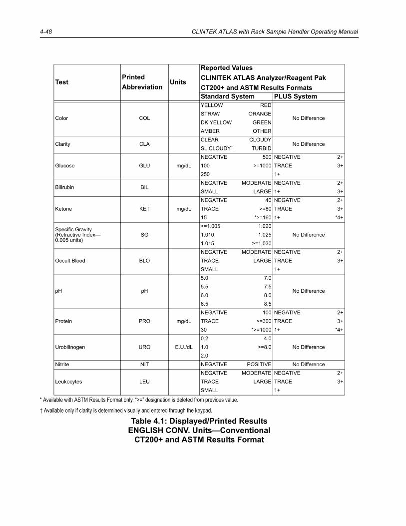
4-48 CLINTEK ATLAS with Rack Sample Handler Operating Manual
* Available with ASTM Results Format only. “>=” designation is deleted from previous value.
† Available only if clarity is determined visually and entered through the keypad.
Table 4.1: Displayed/Printed ResultsENGLISH CONV. Units—Conventional
CT200+ and ASTM Results Format
TestPrintedAbbreviation
Units
Reported ValuesCLINITEK ATLAS Analyzer/Reagent PakCT200+ and ASTM Results FormatsStandard System PLUS System
Color COL
YELLOW RED
No DifferenceSTRAW ORANGEDK YELLOW GREENAMBER OTHER
Clarity CLACLEAR CLOUDY
No DifferenceSL CLOUDY† TURBID
Glucose GLU mg/dLNEGATIVE 500 NEGATIVE 2+100 >=1000 TRACE 3+250 1+
Bilirubin BILNEGATIVE MODERATE NEGATIVE 2+SMALL LARGE 1+ 3+
Ketone KET mg/dLNEGATIVE 40 NEGATIVE 2+TRACE >=80 TRACE 3+15 *>=160 1+ *4+
Specific Gravity(Refractive Index—0.005 units)
SG<=1.005 1.020
No Difference1.010 1.0251.015 >=1.030
Occult Blood BLONEGATIVE MODERATE NEGATIVE 2+TRACE LARGE TRACE 3+SMALL 1+
pH pH
5.0 7.0
No Difference5.5 7.56.0 8.06.5 8.5
Protein PRO mg/dLNEGATIVE 100 NEGATIVE 2+TRACE >=300 TRACE 3+30 *>=1000 1+ *4+
Urobilinogen URO E.U./dL0.2 4.0
No Difference1.0 >=8.02.0
Nitrite NIT NEGATIVE POSITIVE No Difference
Leukocytes LEUNEGATIVE MODERATE NEGATIVE 2+TRACE LARGE TRACE 3+SMALL 1+

CUSTOMIZING THE SOFTWARE 4-49
* Available with ASTM Results Format only. “>=” designation is deleted from previous value.
† Available only if clarity is determined visually and entered through the keypad.
Table 4.2: Displayed/Printed ResultsENGLISH SI
Units—International (SI)CT200+ and ASTM Results Formats
TestPrintedAbbreviation
Units
Reported ValuesCLINITEK ATLAS Analyzer/Reagent PakCT200+ and ASTM Results FormatStandard System PLUS System
Color COL
YELLOW RED
No DifferenceSTRAW ORANGEDK YELLOW GREENAMBER OTHER
Clarity CLACLEAR CLOUDY
No DifferenceSL CLOUDY† TURBID
Glucose GLU mmol/LNEGATIVE 28 NEGATIVE 2+5.5 >=55 TRACE 3+14 1+
Bilirubin BILNEGATIVE MODERATE NEGATIVE 2+SMALL LARGE 1+ 3+
Ketone KET mmol/LNEGATIVE 3.9 NEGATIVE 2+TRACE >=7.8 TRACE 3+1.5 *>=15.6 1+ *4+
Specific Gravity(Refractive Index—0.005 units)
SG<=1.005 1.020
No Difference1.010 1.0251.015 >=1.030
Occult Blood BLDNEGATIVE MODERATE NEGATIVE 2+TRACE LARGE TRACE 3+SMALL 1+
pH pH
5.0 7.0
No Difference5.5 7.56.0 8.06.5 8.5
Protein PRO g/LNEGATIVE 1.0 NEGATIVE 2+TRACE >=3.0 TRACE 3+0.3 *>=10.0 1+ *4+
Urobilinogen UBG µmol/L3.2 66
No Difference16 >=13133
Nitrite NIT NEGATIVE POSITIVE No Difference
Leukocytes LEU Cells/µLNEGATIVE Ca125 NEGATIVE 2+Ca 15 Ca500 TRACE 3+Ca 70 1+

4-50 CLINTEK ATLAS with Rack Sample Handler Operating Manual
* Available with ASTM Results Format only. “>=” designation is deleted from previous value.
† Available only if clarity is determined visually and entered through the keypad.
Table 4.3: Displayed/Printed ResultsFRENCH
Units—ConventionalCT200+ and ASTM Results Formats
TestPrintedAbbreviation
Units
Reported ValuesCLINITEK ATLAS Analyzer/Reagent PakCT200+ and ASTM Results FormatsStandard System PLUS System
Color COL
JAUNE ROUGE
No DifferencePAILLE ORANGEJAUNE FONCE VERTAMBRE AUTRE
Clarity ASPLIMPIDE TROUBLE
No DifferenceLEG TROUB† OPAQUE
Glucose GLU g/LNEGATIF 5.0 NEGATIF 2+1.0 >=10.0 TRACES 3+2.5 1+
Bilirubin BILNEGATIF MOYEN NEGATIF 2+FAIBLE FORT 1+ 3+
Ketone CET g/LNEGATIF 0.4 NEGATIF 2+TRACES >=0.8 TRACES 3+0.15 *>=1.6 1+ *4+
Specific Gravity(Refractive Index—0.005 units)
DEN<=1.005 1.020
No Difference1.010 1.0251.015 >=1.030
Occult Blood SNG GR/µLNEGATIF env. 80 NEGATIF 2+env. 10 env. 200 TRACES 3+env. 25 1+
pH pH
5.0 7.0
No Difference5.5 7.56.0 8.06.5 8.5
Protein PRO g/LNEGATIF 1.0 NEGATIF 2+TRACES >=3.0 TRACES 3+0.3 *>=10.0 1+ *4+
Urobilinogen URO mg/dL0.2 4.0
No Difference1.0 >=8.02.0
Nitrite NIT NEGATIF POSITIF No Difference
Leukocytes LEU GB/µLNEGATIF env. 125 NEGATIF 2+env. 15 env. 500 TRACES 3+env. 70 1+

CUSTOMIZING THE SOFTWARE 4-51
*Available with ASTM Results Format only. “>=” designation is deleted from previous value.
†Available only if clarity is determined visually and entered through the keypad.
Table 4.4: Displayed/Printed ResultsITALIAN
Units—ConventionalCT200+ and ASTM Results Formats
TestPrintedAbbreviation
Units
Reported ValuesCLINITEK ATLAS Analyzer/Reagent PakCT200+ and ASTM Results FormatsStandard System PLUS System
Color COL
GIALLO ARANCIO
No DifferencePAGLIER. ROSSOGIALLO SC VERDEAMBRA ALTRO
Clarity ASPLIMPIDA TORBIDA
No DifferenceLEG. TORB† MOL. TORB
Glucose GLU g/dLNEGATIVO 0.5 NEGATIVO 2+0.1 >=1.0 TRACCE 3+0.25 1+
Bilirubin BILNEGATIVO MEDIO NEGATIVO 2+LEGGERO FORTE 1+ 3+
Ketone KET mg/dLNEGATIVO 40 NEGATIVO 2+TRACCE >=80 TRACCE 3+15 *>=160 1+ *4+
Specific Gravity(Refractive Index—0.005 units selected)
PS
<=1.005 1.020
No Difference1.010 1.025
1.015 >=1.030
Occult Blood SANNEGATIVO MEDIO NEGATIVO 2+TRACCE FORTE TRACCE 3+LEGGERO 1+
pH pH
5.0 7.0
No Difference5.5 7.56.0 8.06.5 8.5
Protein PRO mg/dLNEGATIVO 100 NEGATIVO 2+TRACCE >=300 TRACCE 3+30 *>=1000 1+ *4+
Urobilinogen URO E.U./dL0.2 4.0
No Difference1.0 >=8.02.0
Nitrite NIT NEGATIVO POSITIVO No Difference
Leukocytes LEU Cell/µLNEGATIVO Ca125 NEGATIVO 2+Ca 15 Ca500 TRACCE 3+Ca 70 1+

4-52 CLINTEK ATLAS with Rack Sample Handler Operating Manual
*Available with ASTM Results Format only. “>=” designation is deleted from previous value.
†Available only if clarity is determined visually and entered through the keypad.
Table 4.5: Displayed/Printed ResultsJAPAN
Units—Plus/MinusCT200+ and ASTM Results Formats
TestPrintedAbbreviation
Units
Reported ValuesCLINITEK ATLAS Analyzer/Reagent PakCT200+ and ASTM Results FormatsStandard System PLUS System
Color COL
YELLOW ORANGE
No DifferenceSTRAW REDDK YELLOW GREENAMBER OTHER
Clarity CLA- 1+
No Difference+/-† 2+
Glucose GLU g/dL- 0.5 - 2+0.1 >=1.0 +/- 3+0.25 1+
Bilirubin BIL- 2+
No Difference1+ 3+
Ketone KET- 2+
No Difference+/- 3+1+ *4+
Specific Gravity(Refractive Index—0.005 units selected)
SG
<=1.005 1.020
No Difference1.010 1.025
1.015 >=1.030
Occult Blood OB- 2+
No Difference+/- 3+1+
pH pH
5.0 7.0
No Difference5.5 7.56.0 8.06.5 8.5
Protein PRO mg/dL- 100 - 2++/- >=300 +/- 3+30 *>=1000 1+ *4+
Urobilinogen URO E.U./dL0.1 4.0
No Difference1.0 >=8.02.0
Nitrite NIT - + No Difference
Leukocytes WBC- 2+
No Difference+/- 3+1+

CUSTOMIZING THE SOFTWARE 4-53
*Available with ASTM Results Format only. “>=” designation is deleted from previous value.
†Available only if clarity is determined visually and entered through the keypad.
Table 4.6: Displayed/Printed ResultsSPANISH
Units—ConventionalCT200+ and ASTM Results Formats
TestPrintedAbbreviation
Units
Reported ValuesCLINITEK ATLAS Analyzer/Reagent PakCT200+ and ASTM Results FormatsStandard System PLUS System
Color COL
AMARILLO ANARANJ
No DifferenceCOLURICA ROJIZOAM. OSCURO VERDOSOAMBAR OTROS
Clarity ASPCLARO TURBIA
No DifferenceLIG. TURB† MUY TURB
Glucose GLU mg/dLNEGATIVO 500 NEGATIVO 2+100 >=1000 INDICIO 3+250 1+
Bilirubin BILNEGATIVO MODERADO NEGATIVO 2+BAJO ALTO 1+ 3+
Ketone CET mg/dLNEGATIVO 40 NEGATIVO 2+INDICIO >=80 INDICIO 3+15 *>=160 1+ *4+
Specific Gravity(Refractive Index—0.005 units selected)
DEN
<=1.005 1.020
No Difference1.010 1.025
1.015 >=1.030
Occult Blood SAN eri/µLNEGATIVO Apr 80 NEGATIVO 2+Apr 10 Apr 200 INDICIO 3+Apr 25 1+
pH pH
5.0 7.0
No Difference5.5 7.56.0 8.06.5 8.5
Protein PRO mg/dLNEGATIVO 100 NEGATIVO 2+INDICIO >=300 INDICIO 3+30 *>=1000 1+ *4+
Urobilinogen URO E.U./dL0.2 4.0
No Difference1.0 >=8.02.0
Nitrite NIT NEGATIVO POSITIVO No Difference
Leukocytes LEU cel/µLNEGATIVO Apr 125 NEGATIVO 2+Apr 15 Apr 500 INDICIO 3+Apr 70 1+

4-54 CLINTEK ATLAS with Rack Sample Handler Operating Manual
*Available with ASTM Results Format only. “>=” designation is deleted from previous value.
†Available only if clarity is determined visually and entered through the keypad.
Table 4.7: Displayed/Printed ResultsGERMAN CONV.
Units—ConventionalCT200+ and ASTM Results Formats
TestPrintedAbbreviation
Units
Reported ValuesCLINITEK ATLAS Analyzer/Reagent PakCT200+ and ASTM Results FormatsStandard System PLUS System
Color Farbe
HELL ORANGE
No DifferenceGELB ROTDUNKEL GRUENBRAEUNL. ANDERS
Clarity KlarheitKLAR S.FLOCKIG
No DifferenceFLOCKIG† TRUEB
Glucose GLU mg/dLNEGATIV 500 NEGATIV 2+100 >=1000 SPUR 3+250 1+
Bilirubin BILNEGATIV MAESSIG NEGATIV 2+SCHWACH STARK 1+ 3+
Ketone KET mg/dLNEGATIV 40 NEGATIV 2+SPUR >=80 SPUR 3+15 *>=160 1+ *4+
Specific Gravity(Refractive Index—0.005 units selected)
SG
<=1.005 1.020
No Difference1.010 1.025
1.015 >=1.030
Occult Blood OBL Ery/µL0 Ca 80 NEGATIV 2+Ca 10 Ca 200 SPUR 3+Ca 25 1+
pH pH
5.0 7.0
No Difference5.5 7.56.0 8.06.5 8.5
Protein PRO mg/dLNEGATIV 100 NEGATIV 2+SPUR >=300 SPUR 3+30 *>=1000 1+ *4+
Urobilinogen UBG mg/dL0.2 4.0
No Difference1.0 >=8.02.0
Nitrite NIT NEGATIV POSITIV No Difference
Leukocytes LEU Leu/µL0 Ca 125 NEGATIV 2+Ca 15 Ca 500 SPUR 3+Ca 70 1+

CUSTOMIZING THE SOFTWARE 4-55
*Available with ASTM Results Format only. “>=” designation is deleted from previous value.
†Available only if clarity is determined visually and entered through the keypad.
Table 4.8: Displayed/Printed ResultsGERMAN SI
Units—International (SI)CT200+ and ASTM Results Formats
TestPrintedAbbreviation
Units
Reported ValuesCLINITEK ATLAS Analyzer/Reagent PakCT200+ and ASTM Results FormatsStandard System PLUS System
Color Farbe
HELL ORANGE
No DifferenceGELB ROTDUNKEL GRUENBRAEUNL. ANDERS
Clarity KlarheitKLAR S.FLOCKIG
No DifferenceFLOCKIG† TRUEB
Glucose GLU mmol/LNEGATIV 28 NEGATIV 2+5.5 >=55 SPUR 3+14 1+
Bilirubin BILNEGATIV MAESSIG NEGATIV 2+SCHWACH STARK 1+ 3+
Ketone KET mmol/LNEGATIV 3.9 NEGATIV 2+SPUR >=7.8 SPUR 3+1.5 *>=15.6 1+ *4+
Specific Gravity(Refractive Index—0.005 units selected)
SG
<=1.005 1.020
No Difference1.010 1.025
1.015 >=1.030
Occult Blood OBL Ery/µL0 Ca 80 NEGATIV 2+Ca 10 Ca 200 SPUR 3+Ca 25 1+
pH pH
5.0 7.0
No Difference5.5 7.56.0 8.06.5 8.5
Protein PRO g/LNEGATIV 1.0 NEGATIV 2+SPUR >=3.0 SPUR 3+0.3 *>=10.0 1+ *4+
Urobilinogen UBG µmol/L3.2 66
No Difference16 >=13133
Nitrite NIT NEGATIV POSITIV No Difference
Leukocytes LEU Leu/µL0 Ca 125 NEGATIV 2+Ca 15 Ca 500 SPUR 3+Ca 70 1+
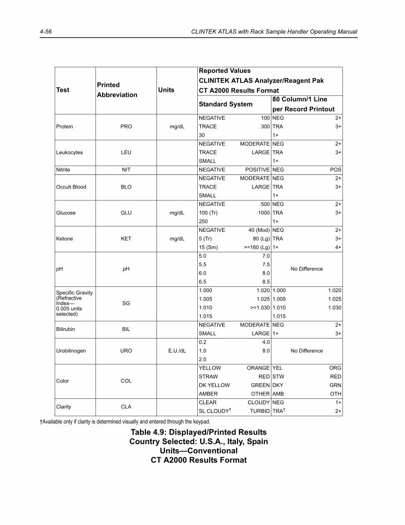
4-56 CLINTEK ATLAS with Rack Sample Handler Operating Manual
†Available only if clarity is determined visually and entered through the keypad.
Table 4.9: Displayed/Printed ResultsCountry Selected: U.S.A., Italy, Spain
Units—ConventionalCT A2000 Results Format
TestPrintedAbbreviation
Units
Reported ValuesCLINITEK ATLAS Analyzer/Reagent PakCT A2000 Results Format
Standard System80 Column/1 Lineper Record Printout
Protein PRO mg/dLNEGATIVE 100 NEG 2+TRACE 300 TRA 3+30 1+
Leukocytes LEUNEGATIVE MODERATE NEG 2+TRACE LARGE TRA 3+SMALL 1+
Nitrite NIT NEGATIVE POSITIVE NEG POS
Occult Blood BLONEGATIVE MODERATE NEG 2+TRACE LARGE TRA 3+SMALL 1+
Glucose GLU mg/dLNEGATIVE 500 NEG 2+100 (Tr) 1000 TRA 3+250 1+
Ketone KET mg/dLNEGATIVE 40 (Mod) NEG 2+5 (Tr) 80 (Lg) TRA 3+15 (Sm) >=160 (Lg) 1+ 4+
pH pH
5.0 7.0
No Difference5.5 7.56.0 8.06.5 8.5
Specific Gravity(Refractive Index—0.005 units selected)
SG
1.000 1.020 1.000 1.0201.005 1.025 1.005 1.0251.010 >=1.030 1.010 1.0301.015 1.015
Bilirubin BILNEGATIVE MODERATE NEG 2+SMALL LARGE 1+ 3+
Urobilinogen URO E.U./dL0.2 4.0
No Difference1.0 8.02.0
Color COL
YELLOW ORANGE YEL ORGSTRAW RED STW REDDK YELLOW GREEN DKY GRNAMBER OTHER AMB OTH
Clarity CLACLEAR CLOUDY NEG 1+SL CLOUDY† TURBID TRA† 2+
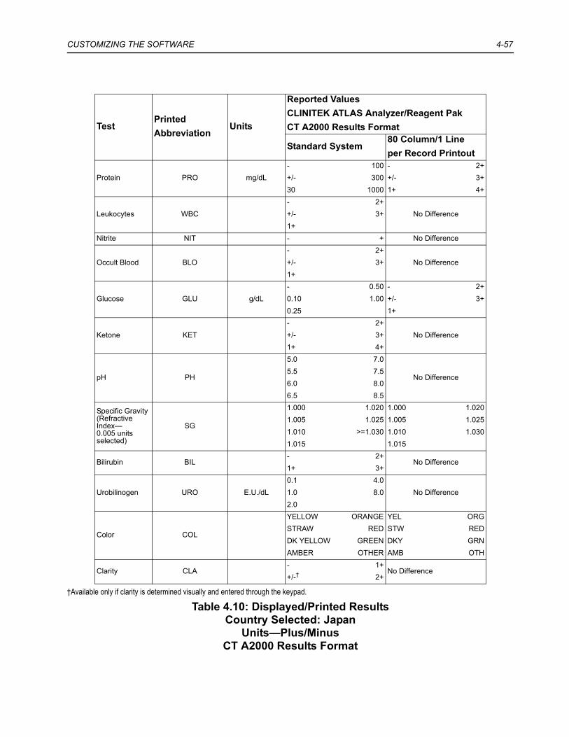
CUSTOMIZING THE SOFTWARE 4-57
†Available only if clarity is determined visually and entered through the keypad.
Table 4.10: Displayed/Printed ResultsCountry Selected: Japan
Units—Plus/MinusCT A2000 Results Format
TestPrintedAbbreviation
Units
Reported ValuesCLINITEK ATLAS Analyzer/Reagent PakCT A2000 Results Format
Standard System80 Column/1 Lineper Record Printout
Protein PRO mg/dL- 100 - 2++/- 300 +/- 3+30 1000 1+ 4+
Leukocytes WBC- 2+
No Difference+/- 3+1+
Nitrite NIT - + No Difference
Occult Blood BLO- 2+
No Difference+/- 3+1+
Glucose GLU g/dL- 0.50 - 2+0.10 1.00 +/- 3+0.25 1+
Ketone KET- 2+
No Difference+/- 3+1+ 4+
pH PH
5.0 7.0
No Difference5.5 7.56.0 8.06.5 8.5
Specific Gravity(Refractive Index—0.005 units selected)
SG
1.000 1.020 1.000 1.0201.005 1.025 1.005 1.0251.010 >=1.030 1.010 1.0301.015 1.015
Bilirubin BIL- 2+
No Difference1+ 3+
Urobilinogen URO E.U./dL0.1 4.0
No Difference1.0 8.02.0
Color COL
YELLOW ORANGE YEL ORGSTRAW RED STW REDDK YELLOW GREEN DKY GRNAMBER OTHER AMB OTH
Clarity CLA- 1+
No Difference+/-† 2+

4-58 CLINTEK ATLAS with Rack Sample Handler Operating Manual

5 LOADING THE REAGENT ROLL
Step-by-step instructions for loading and unloading the CLINITEK ATLAS Reagent Pak are given on the screen display and are explained in detail in this section.
The SG well must be cleaned each time a new reagent roll is loaded.
The instrument must also be calibrated:
• if the lot number of the reagent roll is different from that previously entered;• if more than 24 hours have elapsed since the last calibration was performed.
Testing of control specimens is strongly recommended following calibration. They can be tested following completion of the Calibration Mode by entering the Control Analyze Mode (see Section 6, CALIBRATION/TESTING CONTROLS).
If calibration is to be performed, be sure you have available a tube of bleach (5.25% sodium hypochlorite), the CLINITEK ATLAS Rinse Additive and CLINITEK ATLAS Calibrators #1, #2, #3, and #4 before entering the Load Reagent routine. Two mL of the Rinse Additive are added to 1000 mL of distilled or deionized water to make the Rinse Solution.
NOTE: The reagent loading sequence can be aborted at any time by pressing the STANDBY key ( ).
1. Press 4 from the Main Menu to load the reagent roll.
The display changes to the first set of Load Reagent instructions. The display will provide ongoing instructions for loading the reagent, which will be repeated and supplemented in this section.
2. Remove racks from the Sample Handler, as necessary, to open the doors.
BIOHAZARDWear personal protective equipment. Use universal precautions. Refer to Appendix C, Protecting Yourself from Biohazards for recommended precautions when working with biohazardous materials.
CAUTIONUse of bleach stronger than 5.25% sodium hypochlorite will damage the SG sensor. Therefore, check the concentration of sodium hypochlorite in the bleach being used. If it is higher than 5.25%, the bleach must be diluted with distilled water. For example, if the bleach is 6% sodium hypochlorite (e.g., Ultra Clorox), add 0.75 mL of water to 5 mL of the 6% bleach and mix gently.

5-2 CLINTEK ATLAS with Rack Sample Handler Operating Manual
3. Open the right instrument door first, turning the small knob counterclockwise to release the latch. Then open the left door.
The loading diagram is located on the inside of the left door. The same diagram is shown at the end of this section. Refer to this diagram for each of the remaining steps.
4. Press the CONTINUE softkey and continue to Step 6:
• if there are no reagents already loaded;• if the entire backing is already clear of the readhead (“D”).Press the ADVANCE softkey if a reagent roll is loaded into the instrument.
5. Press CONTINUE when the entire plastic backing is free of the readhead.
If there is a problem with the advancement, press HALT to stop the mechanism. Correct the problem, then press ADVANCE again.
After CONTINUE is pressed, the display changes to allow entry of the lot number of the new CLINITEK ATLAS Reagent Pak.
6. Enter the lot number of the reagent. The lot number is printed on the plastic canister. For numeric entries, use the keypad. For alphabetic and character entries, use the softkeys.
a. Press the softkey under the correct letter (or character) until the letter is displayed at the cursor. The displayed letter (or character) will be accepted when any other key is pressed. If a second letter is required that uses the same softkey, press to accept the first letter and move the cursor one position to the right.
b. If a space is needed, press the softkey under the symbol “ ”. This symbol will be shown above the cursor until it is accepted, at which time a space will appear on the data entry line.
c. If an error is made, press to erase the previously entered character on the display.
d. Press when the lot number has been correctly entered.The display will provide ongoing instructions for loading the new reagent roll:

LOADING THE REAGENT ROLL 5-3
7. Remove the used reagent roll from “G” (the takeup reel) as follows:
a. Rotate “G” until the notch on the back plate is aligned with the hook on the back wall of the instrument. Use the hook to lock the back plate into position.
b. Firmly grasp the used reagent roll and turn it counterclockwise (the same direction as the roll is wound) about 1/4 turn. This loosens the tension on the roll and allows it to be removed from “G.” The reagent roll will be very difficult to remove if you do not first loosen the tension.
c. Holding “G” at its exposed end, turn it firmly counterclockwise to unlock “G” from the back plate (Figure 5-1).
d. Remove “G” with the used reagent roll wound around it.
Figure 5-1
e. Slide the used roll off of “G” and into a plastic bag. You may need to push it slightly to get it started. Close the bag securely and discard appropriately.
f. Align one of the lines on “G” with the “Unlock” symbol on the back plate.g. Push “G” in as far as it will go. Then firmly turn “G” clockwise until the line
aligns with the “Lock” symbol. h. Remove the hook from the back plate so “G” is free to rotate.
8. Wipe “E” (Tension Sprocket) with a damp paper towel.
E Tension SprocketF Idler/Stationary Rod SleeveG Take Up Reel

5-4 CLINTEK ATLAS with Rack Sample Handler Operating Manual
9. Remove “F” (stationary rod sleeve) by pulling it forward (Figure 5-2). Clean the sleeve thoroughly, using a wet paper towel and/or by soaking. Be sure to remove all built-up residue. Replace the sleeve onto its holding stem, pushing it all the way on.
A replacement sleeve is included in the Supply Kit. This one can be used while the other one is being cleaned.
Figure 5-2
10. Clean “D” (the readheads). Remove the platform and thoroughly wipe the underside with a damp, lint-free cloth or paper towel until there is no sign of dirty streaking. Then replace the platform.
Refer to Section 9, MAINTENANCE, Periodic Maintenance for complete information on this procedure.
NOTE: Failure to clean the readheads before loading each new reagent roll may cause a Dry Calibration Error.
11. Press CONTINUE when finished with the above steps.
The display continues to the next set of instructions.
12. Open the reagent compartment door by turning the knob counterclockwise. Remove and discard the old packet of desiccant.
13. Lower “B” by rotating the handle on “B” counterclockwise as far as it will rotate. While holding the handle in this position, press down firmly on “B” until it drops down.
14. Load the reagent onto the instrument.
F Idler/Stationary Rod Sleeve

LOADING THE REAGENT ROLL 5-5
a. Carefully remove the foil lid from the canister. Leave the large packet of desiccant in the center of the roll in place.
b. Grasp the reagent roll, holding the desiccant packet in place, and lift it from the canister.
c. Partially insert the roll into the reagent compartment with the clear plastic leader unrolling over the top (counterclockwise) and the black stripe at the back side (Figure 5-3).
d. Be sure the leader is positioned to the left of “A” (a stationary rod). e. While still holding the roll with one hand, remove the tape that secures the
leader. Then push the roll the rest of the way into the reagent compartment.
Figure 5-3
NOTE: Before inserting the reagent roll, check that the guide plate attached to “A” is in its proper position. The guide pins on the right side of the plate should be laying inside the two small grooves in the rounded edge of the reagent compartment.
15. Follow the instructions given on the prompts and refer to the diagram on the instrument door to thread the reagent leader.
E Tension SprocketF Idler/Stationary RodG Take Up Reel

5-6 CLINTEK ATLAS with Rack Sample Handler Operating Manual
Gently guide the leader:
• behind and under “A” (the reagent format guard),• under “C” (the first rotating spool with pins), • through “D” (the readhead assembly), • over “E” (the second rotating spool with pins), • and under “F” (the stationary rod).
16. Press CONTINUE when these steps have been completed.
The display changes to the next set of instructions.
17. Turn “G” (the takeup reel) until you locate the slot that has two white lines in the middle. The slot is wider at the front and back than at the center.
a. Insert the end of the leader into the wider part of this step-ups it in about an inch, and slide it to the center, narrower part (Figure 5-4).
b. While holding the leader in the slot, rotate “G” counterclockwise until the leader is securely wound around the reel.
c. Continue rotating “G” until the holes along the side of the leader have been engaged by the pins on spool “C.”
Figure 5-4
18. Raise “B” by lifting up firmly on the handle of “B” until “B” snaps up. Then rotate the handle fully clockwise. Make sure that it slides into the small notch on the plate under “B.”
A Reagent Format GuardC Drive Sprocket Assembly

LOADING THE REAGENT ROLL 5-7
19. When these steps are complete, press CONTINUE.
The takeup reel will rotate several turns to the point at which the holes on each side of the leader are past the readheads.
a. If there is no advancement, or if there is a problem in the advancement, press HALT.
b. Correct the problem, ensuring that the holes in the plastic leader are engaged on the pins of “C.” Then press ADVANCE to begin advancing the reagent again.After the reagent movement ends, the display changes the next set of instructions.
c. Follow the prompt, ensuring that the holes on each side of the leader are fitted onto the pins of “E.” You may need to press ADVANCE one or more times, then rotate “E” slightly to fit the pins into the holes.
d. Press CONTINUE when all steps are complete.The instrument will automatically advance the backing until the first strip is located. When the first strip is detected, the reagent installation is complete. The display will prompt: “Close and latch reagent compartment door.”
20. Close the reagent compartment door and turn the knob fully clockwise.
21. Complete the following steps prior to calibration.
a. The prompt changes to “Check and refill rinse solution container” and “Close Analyzer doors.” Check the volume of Rinse Solution remaining in the container and ensure that at least one liter is available. If using the bottle supplied with the Sample Handler, prepare a fresh bottle of Rinse Solution. Empty any remaining Rinse Solution from the rinse bottle, then fill with 1000 mL of distilled or deionized water. Add 2 mL of CLINITEK ATLAS Rinse Additive (Product Number 5007A) and swirl gently to mix.
b. Replace the rinse bottle, then close both instrument doors (closing the left door first).
c. Remove the tubing from the waste bottle and empty the bottle if it is more than half full. Replace it into its proper position and replace the tubing.
This completes the Load Reagent process.
• If 24 hours or more have elapsed since the last calibration or if the lot number of the reagent roll just loaded is different from the previous reagent, the instrument will proceed to the automatic calibration sequence (see Section 6).
• If the last calibration was performed within the previous 24 hours and the lot number of the reagent roll has not changed, calibration is optional. However, you must clean the SG Well before testing a new batch of samples.
Press CALIBRATE to enter the Calibration Routine (refer to Section 6). Press CLEAN SG to begin the SG Well Cleaning cycle. Or press CONTINUE to return to the Standby Mode. The SG Well must be cleaned before a new run can be started.

5-8 CLINTEK ATLAS with Rack Sample Handler Operating Manual
Figure 5-5 Loading Diagram
A Reagent Format GuardB Reagent Guide ShoeC Drive Sprocket AssemblyD ReadheadE Tension SprocketF Idler/Stationary Rod SleeveG Take up ReelH Desiccant Pillow/Packet

6 CALIBRATION/TESTING CONTROLS
Calibration
Calibration is required:
• any time the reagent roll is replaced with another of a different lot number;• when a reagent roll is replaced with another of the same lot number, and 24 hours
have elapsed since the previous calibration;• if some error conditions occur;• if the ambient room temperature has changed by more than 5° C.
The instrument can also be recalibrated at any time by pressing CALIBRATE from the Analyze Mode. To enter the Analyze Mode, press ANALYZE from the Standby Mode (Ready for Testing screen). See Section 7, ROUTINE OPERATION for details.
NOTE: If the instrument has been off for longer than one hour, prime the pump (by pressing 5 from the Main Menu). Then leave the instrument ON for at least one hour (to rehydrate the SG well) before re-assuming operation.
Before entering the Calibration Mode, have the following items available:
• Sample Tubes: See Section 13, SERVICE, SUPPLIES AND PARTS for tube specifications.
• CLINITEK ATLAS Calibration Kit: (Product No. 5018A)(Calibrator #4 [Clarity] is also available separately as Product No. 5006.)
• Tube of Bleach: Use household bleach with a sodium hypochlorite concentration of 5.25%. This bleach solution is used to clean the SG well in the instrument. A fresh tube of bleach should be used each day.
CAUTIONUse of bleach stronger than 5.25% sodium hypochlorite will damage the SG sensor. Therefore, check the concentration of sodium hypochlorite in the bleach being used. If it is higher than 5.25%, the bleach must be diluted with distilled water. For example, if the bleach is 6% sodium hypochlorite (e.g., Ultra Clorox), add 0.75 mL of water to 5 mL of the 6% bleach and mix gently.
BIOHAZARDWear personal protective equipment. Use universal precautions. Refer to Appendix C, Protecting Yourself from Biohazards for recommended precautions when working with biohazardous materials.

6-2 CLINTEK ATLAS with Rack Sample Handler Operating Manual
1. Prepare the tubes of calibration and cleaning solutions as follows:
a. Pour at least 2 mL of 5.25% sodium hypochlorite into a properly labeled sample tube. This tube may be reused throughout the day as needed without discarding. However, it must always contain at least 2 mL.
b. Pour each of the four Calibration Solutions (from the Calibration Kit) into properly labeled sample tubes (one tube per solution).• The tubes of Calibrator #1, #2, and #3 must each contain a minimum of 3
mL of solution to allow for duplicate testing.• The tube of Calibrator #4 must contain a minimum of 5 mL of solution to
allow the instrument to automatically repeat the clarity calibration sequence when needed.
c. Allow all solutions to warm to room temperature before being used.NOTE: If you are not reporting clarity, Calibrator 4 is not required for calibration.
2. Enter the calibration routine by responding to the instrument prompt, or by pressing the CALIBRATE softkey
3. The first display shows the previously entered lot numbers for the calibrators, if numbers have been entered. If all the lot numbers are correct, press CONTINUE.
4. If any of the lot numbers are incorrect, or if none are entered, press UP or DOWN to move the arrow to the appropriate line.
The arrow moves in a circular pattern. If it is located at the bottom line (Calibrator 4) and DOWN is pressed, it will move to the top line (Calibrator 1), and vice-versa.
5. When the arrow is pointing to the calibrator lot number that needs to be changed, press . The display will change to allow new numbers (up to 13 digits) to be entered. The
cursor moves to the first digit of the lot number.
6. Enter the new lot number in the same manner used for entering the reagent roll lot number. For numeric entries, use the keypad. For alphabetic and character entries, use the softkeys.
• Press the softkey under the correct letter (or character) until the letter is displayed at the cursor. The displayed letter will be accepted when any other key is pressed. If a second letter is required that uses the same softkey, press to accept the first letter and move the cursor one position to the right.
• If a space is needed, press the softkey under the displayed symbol “ ”. This symbol will be shown above the cursor until it is accepted (by pressing or another key). Then a space will appear on the data entry line.
• If an error is made, press to erase the previously entered character on the display. If there are no characters remaining, press to redisplay the number that was previously entered into memory.
• Press when the lot number has been correctly entered. The display will return to that shown in Step 1 above.

CALIBRATION/TESTING CONTROLS 6-3
7. Enter the lot number for the next calibrator in the same manner as described in Steps 3-6 above. Repeat for each line, as needed.
8. When all calibrator lot numbers have been correctly entered, press CONTINUE to continue in the Calibration Mode.
9. Place the tube of bleach and the four tubes of Calibrator Solution into a specimen rack in the following order:
• 1st Test Position - Bleach• 2nd Test Position - Cal 4• 3rd Test Position - Cal 1• 4th Test Position - Cal 2• 5th Test Position - Cal 3
10. Place the rack onto the right side of the Sample Handler, with the open side facing to the back (Figure 6-1). Push the rack to the right so it is aligned along the retaining rail. Then press CONTINUE on the Analyzer.
Figure 6-1
If the instrument has just been turned on and the five-minute warming time has elapsed, the calibration sequence begins immediately.
If the lamp has been off for longer than ten minutes, it must warm for 45 seconds before testing begins. The display shows the message “Optics Stabilizing” and a time bar indicates the time remaining. The rack is moved into position for testing, beginning with the cleaning cycle.
The time bar decreases as the cleaning cycle progresses (about 3 minutes). It is followed immediately by the dry pad calibration. Readings are taken on the dry reagent pads at each of the two readheads. These readings are used to calibrate the optical system. The screen changes to reflect the status of the calibration sequence.

6-4 CLINTEK ATLAS with Rack Sample Handler Operating Manual
Again, the time bar decreases as the dry pad calibration progresses (about 45 seconds). When the readings are complete, the instrument will rewind the strips just read so the first strip is in position to be wetted during the wet calibration sequence.
The display continually updates the status of several factors:
Strips Remaining: the number of reagent strips remaining in the reagent roll. A newly installed roll resets the counter to 490 strips. With each strip used, the display decreases until it reaches “1.” The display will remain at “1” until the instrument detects the final strip. (There may be more than 490 strips in the reagent roll.)Tray ID: the sequential number of the specimen rack being tested.Tube Number: the tube position at which testing is being performed.
The display will change with each calibrator tested, decrementing the number of strips remaining and incrementing the tube number. Calibrator #4 is tested first, without the use of any reagent strips. Calibrators #1, #2, and #3 are then tested, each in duplicate.
After all calibrators have been pipetted and while the instrument is analyzing the results, the display will show the message “Completing Calibration Process. Please Wait.”
Upon the successful completion of the calibration mode, the “Calibration Successful” screen is displayed. The display then returns to the Standby Mode (Ready for Testing screen).
11. Remove the calibration rack after it has been moved to left side of the Sample Handler. Either controls or routine samples can be processed. Place the rack with the control solutions or the racks of samples onto the Sample Handler (see Section 7).
NOTE: If Auto. Run After Cal. was selected through the Set Up Analyzer routine, the instrument will proceed automatically to the ROUTINE Analyze Mode. It will begin analysis of specimens in any additional racks that have been loaded onto the Sample Handler. Refer to Section 7 for information on the Analyze routine.NOTE: If an error occurs during the Calibration Mode, an appropriate screen will be displayed. The problem, a brief description of the remedy, and in some cases an error number are displayed. Some errors require more than one screen to provide a complete description of the problem or the action needed. These screens will display a softkey of MORE that will move the dis-play to the continuing information. The screens will also offer one or more softkeys in order to correct the error. Refer to Section 11, ANALYZER DIAGNOSTICS for further information.

CALIBRATION/TESTING CONTROLS 6-5
Testing Controls
Controls can be tested through the Control Analyze Mode. It is strongly recommended that controls be analyzed after calibration. Additional control runs may be performed as required by individual laboratory practices.
NOTE: If 5 control samples are analyzed consecutively (with no other urine specimens run between the controls), it is strongly recommended that the SG well be cleaned immediately after the fifth control, before analyzing any patient specimens or additional controls.
Before entering the Control Analyze Mode, prepare the CLINITEK ATLAS Control Solution(s) using CLINITEK ATLAS Positive or Negative Control Strips. Follow the instructions in the insert accompanying the product.
The Control Solutions are stable for 8 hours after preparation, except for bilirubin in the Positive Control. It is stable for 3 hours under normal laboratory conditions.
Prepare additional or alternative controls according to the directions accompanying the product. Pour at least 2 mL of each control into properly labeled tubes. A total of three controls may be run in a single Control run.
1. Press ANALYZE from the Standby Mode (Ready for Testing screen) to enter the Control Analyze Mode.
2. Press CONTROL.
3. Place up to three tubes of control solution into a specimen rack in the following positions:
• Control 1 - Position 1• Control 2 - Position 2• Control 3 - Position 3
4. Place the rack onto the right side of the Sample Handler, with the open side facing to the back.
5. Push the rack to the right so it is aligned along the retaining rail.
6. Press CONTINUE on the Analyzer.
NOTE: The control tubes must be placed in the rack in the correct positions. Otherwise, one or more controls will not be tested.
BIOHAZARDWear personal protective equipment. Use universal precautions. Refer to Appendix C, Protecting Yourself from Biohazards for recommended precautions when working with biohazardous materials.

6-6 CLINTEK ATLAS with Rack Sample Handler Operating Manual
7. The next display shows the previously entered lot numbers for the controls, if numbers have been entered. If all the lot numbers are correct, press CONTINUE. The Control Analyze Mode will begin.
8. If any of the lot numbers are incorrect, or if none are entered, press UP or DOWN to move the arrow to the appropriate line.
9. When the arrow is pointing to the control lot number that needs to be changed, press . The display will change to allow new numbers (up to 13 digits) to be entered. The cursor moves to the first digit of the lot number.
10. Enter the new lot number in the same manner used for entering the reagent roll and calibrator lot numbers. For numeric entries, use the keypad. For alphabetic and character entries, use the softkeys.
• Press the softkey under the correct letter (or character) until the letter is displayed at the cursor. The displayed letter will be accepted when any other key is pressed. If a second letter is required that uses the same softkey, press to accept the first letter and move the cursor one position to the right.
• If a space is needed, press the softkey under the displayed symbol “ ”. This symbol will be shown above the cursor until it is accepted (by pressing or another key). Then a space will appear on the data entry line.
• If an error is made, press to erase the previously entered character on the display. If there are no characters remaining, press to redisplay the number that was previously entered into memory.
• Press when the lot number has been correctly entered. The display will return to that shown in Step 3 above.
11. Enter the lot number for the next control in the same manner as described in Steps 7-10 above. Repeat for each line, as needed.
12. When all control lot numbers have been correctly entered, press CONTINUE.
The specimen rack is moved into position for testing. The instrument will then search for a tube in position 1.
The status of the Strips Remaining, Tray ID, and Tube Number is continually updated on the display.
The display also shows the Specimen ID (the identification number of the specimen), if specimen IDs are being used. If a bar-coded label is read, the number is displayed. Otherwise, the number can be entered at the end of the run.
The display will change with each control tested, decrementing the number of strips remaining and incrementing the tube number. In addition, the message on the display will change to signify which control is being tested (1st through 3rd). Each control is tested once.
After all controls have been pipetted and while the instrument is analyzing the results, the display will show the message “Analyzer Completing Test Cycle. Please wait.”
13. Remove the control rack after it has been moved to the left side of the Sample Handler.

CALIBRATION/TESTING CONTROLS 6-7
As each set of results becomes available, they are displayed for review and printing. The specimen ID, color and/or clarity can be entered at the first screen, if they are being determined by the operator, and this option was selected as ON. (see End of Run Review‚ page 7-14), When all necessary information is available, the results are displayed.
The Control Results screen shows the following information:
Tray/Tube: the sequential rack number and the tube position of the control record being displayed.Test Type: the type of Analyze Mode that was used for this specimen (Control).Seq: The sequential number that was assigned to the record. A prefix of “C” or “CN” (depending upon the Results Format selected) is assigned to each sequence number.Time and Date: the date and time at which the control was aspirated for testing.ID: the identification number (if being used) of the specimen.Lot #: the lot number that was entered at the beginning of the Control Analyze Mode for the control in the designated position.
14. Review the control record, then press CONTINUE.
Abnormal results are not flagged on the control records. If results for another control are available, the new record will be displayed.
15. Press CONTINUE after each record. If Print Control Results and/or Send Control Results have been selected as ON (through Set Up Analyzer Routine - Instrument‚ page 4-8), the control results will be printed and/or transmitted to a computer as soon as they are available.
When the last record has been displayed, the display returns to the Ready for Testing screen (Standby Mode) from which the Routine Analyze Mode can be requested.

6-8 CLINTEK ATLAS with Rack Sample Handler Operating Manual
If Control Results are Out of Range
If CLINITEK ATLAS Control Solutions are used, they should produce the values stated in the package insert for the CLINITEK ATLAS Positive and Negative Control Strips. If the results obtained for either of the Control Solutions fall outside of the ranges assigned to the control, one or more of the following errors may have occurred. Check each possibility in the order given.
1. The Control Solution may have deteriorated. Prepare a fresh Control Solution and reassay the control.
2. The existing calibration is invalid because the ambient room temperature has changed by more than 5° C from the last calibration. Recalibrate the instrument, using fresh calibration solutions, then reassay the control.
3. The CLINITEK ATLAS Control Strips are deteriorated. Obtain a fresh bottle of CLINITEK ATLAS Control Strips and prepare a fresh Control Solution. Assay the fresh Control Solution.
4. The reagent roll is deteriorated. Load a new reagent roll, calibrate the instrument, and reassay the Control Solution.
5. The CLINITEK ATLAS Analyzer is malfunctioning. Refer to Section 11, ANALYZER DIAGNOSTICS or contact the your local technical service provider for assistance (see Section 13, SERVICE, SUPPLIES AND PARTS for further service information).

7 ROUTINE OPERATION
Standby Mode — Analyzer
After power up, the machine will go through a five-minute warming period. If calibration is not performed, the instrument will enter the Standby mode.
The Ready for Testing screen will be displayed. The Ready for Testing screen shows the following information:
Strips Remaining: the number of strips (minimum) that are remaining in the reagent roll. A new reagent roll contains at least 490 strips. This display counts down with each strip that is used. The display will remain at “1” until the last strip is detected.
Reagent Use Life: the amount of time remaining that the reagent roll can be used. A reagent roll can be used for 14 days from the time of installation.
A valid calibration must be in memory before any testing can occur. If the instrument has not been calibrated since a new reagent roll was installed, “Analyzer Not Calibrated” will be displayed on the warning line. This warning will not be displayed if the last calibration was performed within the previous 24 hours of loading the new reagent roll and if the lot number did not change.
When the Reagent Use Life display reaches 0 days, the remaining life will be displayed in hours. Once the use life has passed, the warning “Reagent Use Life Expired” will be displayed. A new reagent roll must be installed before continuing.
Reagent Pak Name: This field identifies the reagent pack name and should be left as the default “Atlas 10”.
Next Test Sequence: the sequence number that will be assigned to the next routine sample to be analyzed. The beginning sequence number can be changed through the Main Menu.
Next STAT Sequence: the sequence number that will be assigned to the next STAT sample to be analyzed. The STAT series of numbers uses an “S” prefix (or “ST” with the CT A2000 format). The sequential number reverts back to 001 (00001 or 01) every 24 hours. The time at which this occurs can be changed through the Set Up Analyzer routine.
In addition, the following softkey options are listed on the Ready for Testing screen:
ANALYZE: activates the Analyze Mode, as described in Routine Analysis‚ page 7-5.
STATUS: displays the status of the instrument’s memory and communication ports (see STATUS Display‚ page 2-4).
MAIN MENU: returns the display to the Main Menu.

7-2 CLINTEK ATLAS with Rack Sample Handler Operating Manual
Standby Mode — Sample Handler
The Rack Sample Handler LCD also displays a Standby screen. The screen may display one of several messages relating to the last run:
Stop Marker: The run was stopped because the stop marker was detected.
Rack End: The number of racks that were detected at the beginning of the run were analyzed.
No Tube: The run was stopped because 10 consecutive empty tube positions were detected (not necessarily a single empty rack).
No rack: No racks were detected in the Sample Handler when the run was started.
BC Err: The bar-coded label on at least one tube was unable to be read. Displayed only if the bar code reader is being used.
NOTE: The first two messages are displayed only if the Rack Circulation function has been selected as ON through the User Setup Mode (see User Setup Mode—Sample Handler‚ page 4-1).
The system is ready for routine testing when the Standby screen is displayed on the Rack Sample Handler and the Ready for Testing screen is displayed on the Analyzer. However, before starting each new run, several parameters on the Sample Handler should be reviewed. These are described next.

ROUTINE OPERATION 7-3
Menu Mode - Sample Handler
The Menu Mode is entered from the Rack Handler Standby screen by pressing the key located beneath the word Menu.
Throughout the Menu Mode, pressing ESC returns the display to the Standby screen. Pressing Menu changes the display to the next option in the mode.
Bar Code Error
If any bar code errors have been recorded from a previous run, the Bar Code Error screen displays the number of errors.
1. Press ENT to display the specimen numbers for which bar code errors have been recorded and/or to clear the bar code errors.
The screen shows the rack and tube number of the last specimen that was assayed and of the first tube for which the bar code was not able to be read.
2. Press the appropriate key as follows:
• Press Next to view each specimen number (rack and tube number) for which a bar code error is recorded. Pressing Next also erases the displayed “Err” number from memory. This key is not displayed if only one error was recorded.
Locate the appropriate tubes and enter the ID number during the End of Run Review, either manually or using the handheld bar code scanner.NOTE: If more than 20 errors have been detected (“0” was selected as the Bar Code Error Limit in the User Setup Mode), the message “Too Many Errors” will be displayed after 20 errors have been viewed.
• To clear (erase) the entire list without review, press and hold the All CLR key for 3 seconds.
• Press CONT to return to the Standby screen.
NOTE: If the BC Err screen is displayed for longer than 16 seconds without any key being pressed, the display will automatically revert back to the previous screen without clearing the errors.

7-4 CLINTEK ATLAS with Rack Sample Handler Operating Manual
Starting Rack Number
The number of the next rack to be processed can be changed if the Rack No. Reset option was selected as Key through the User Setup Mode (see Section 4).
NOTE: If Rack No. Reset was set to RUN, this option is not displayed.
1. Press Menu from the Standby screen to reset the starting rack number.
2. Press ENT to select an option for changing the starting rack number:
• Press Reset to change the rack number to “1.”
• Press CONT to specify the number (from 1 to 999). A new screen is displayed, with “Up” and “Down” keys. Press these keys as needed until the preferred rack number is displayed. Press CONT to accept the displayed number.
3. The display then returns to the Rack No. screen. Press Menu to continue to the next option.
Starting Sample Number
The Start Sample screen allows the user to specify the tube number within the rack that is to be processed first.
Each time Up is pressed, the Start Sample number increases by one digit from “1” to “10,” then returns to “1.”
1. Press Up as needed until the preferred starting sample number is displayed.
2. Press Menu to accept the displayed number.
3. Press Menu again to continue to the next option (User Setup), or press ESC to return to the Standby screen.

ROUTINE OPERATION 7-5
Routine Analysis
Ensure that the installed reagent roll is within its use life. If the reagent use life has been exceeded, the message “REAGENT USE LIFE EXPIRED. The use life of the reagent has expired. You must load a reagent.” will be displayed.
The Analyze Mode will not begin until a new reagent roll has been loaded. Press the softkey under the option LOAD REAGENT to access the routine directly from this screen. Refer to Section 5, LOADING THE REAGENT ROLL, for complete information.
Prepare Specimen Racks
Prepare the racks of patient specimens for testing.
NOTE: Urine specimens that are visibly mucoid or bloody should not be analyzed on this instrument. Also, a large amount of foam on top of a specimen may cause inaccurate results or a dispensing error.
1. Allow the specimens to reach room temperature if they have been refrigerated. Test the specimens within two hours after reaching room temperature (or after voiding if not refrigerated), sooner if testing bilirubin or urobilinogen.
2. Mix each specimen thoroughly.
3. Pour at least 2 ml of each specimen into an appropriately labeled specimen tube.
4. Load the tubes of patient specimens into the racks. Be sure the barcode labels are placed vertically on the tube. A skew of greater than 5° may result in reading problems (Figure 7-1). Each tube must be placed in the rack so the bar code is facing the open side of the rack. Ensure that the tubes are properly seated, skewed tubes are likely to interfere with the pipette.
NOTE: • The Analyzer will end the run if 10 consecutive empty positions are detected (not
necessarily a single empty rack). Therefore, it is suggested that you always load tubes beginning with position 1 in each rack. This will ensure that no more than nine empty positions are detected consecutively.
BIOHAZARDWear personal protective equipment. Use universal precautions. Refer to Appendix C, Protecting Yourself from Biohazards for recommended precautions when working with biohazardous materials.

7-6 CLINTEK ATLAS with Rack Sample Handler Operating Manual
Figure 7-1
1 Perpendicular2 5° skew

ROUTINE OPERATION 7-7
Place Racks onto Sample Handler1. Place the racks onto the Sample Handler with the open side of each rack facing the back
(Figure 7-2).
Figure 7-2
• If Rack Circulation is set to OFF, load a maximum of 10 racks onto the right side (infeed).
• If Rack Circulation is set to ON, load the first 10 racks onto the right side and load a maximum of 10 more racks onto the left side. Never add racks to the circulation area across the front of the instrument. Racks in this area are not detected and will cause a rack jam error.
NOTE: Each side of the Sample Handler holds 11 racks. However, a rack jam will occur if you load more than 10 racks onto either side.
2. Push all racks to the right, so they are aligned along the retaining rail.
Rack Circulation OFF
If Rack Circulation was selected as OFF through the User Setup Mode, the first rack is moved into position for sampling. After all tubes have been tested, the rack is moved to the left and the second rack moved into position. This process continues until 10 racks have accumulated on the left (outfeed) side, at which time the instrument stops processing and returns to the Standby Mode (Ready for Testing screen).
NOTE: Additional racks can be added anytime before testing begins on the next to last tube in the last rack. Load the additional racks when the racks are not moving. If additional racks are added to the right side, racks must be removed from the left side before 10 racks have accumulated. Testing will stop when 10 racks have accumulated on the left side.

7-8 CLINTEK ATLAS with Rack Sample Handler Operating Manual
Rack Circulation ON; Stop by 20Rack
If Rack Circulation is ON and Circulation Stop by 20Rack was selected, the number of racks in each side will be counted before processing begins. This number is stored in memory as the maximum number of racks to be processed. When the circulation function begins, racks are moved across the front of the Sample Handler from the left side to the right. Processing stops and the instrument returns to the Standby Mode after the stored number of racks has been processed.
NOTE: • Do not add or remove racks from either side after processing has started! If racks are
added, the same number of racks will be left unprocessed when the instrument returns to Standby, and the error message “#19 Rack Remained” will be displayed. If any unprocessed racks are removed, the same number of previously tested racks will be retested.
• If a rack jam occurs, the Sample Handler will recount and reset the number of racks to be tested. Therefore, any processed racks should be removed to prevent those racks from being retested.
Rack Circulation ON; Stop by Marker
If Rack Circulation is ON and Circulation Stop by Marker was selected, processing begins without counting the number of racks present, and the circulation function operates in the same manner as described in Rack Circulation ON; Stop by 20Rack previously. If the addition of racks in the midst of a run is anticipated, this selection is recommended. Processing is stopped by placing the Stop Marker into the final rack to be tested, following the last specimen.
If no Stop Marker is used, processing can also be stopped by:
• placing an empty rack after the last rack to be tested; or• removing all racks from the left side after they have been tested (before ten racks
have accumulated) so there are no more racks being transferred to the right side.NOTE: It is the operator’s responsibility to ensure that the Stop Marker is in place, or that racks are removed after they have been processed. Otherwise, processed racks will continue to circulate, and specimens will be tested again.
Analysis1. Ensure that the Standby screen is being displayed on the Sample Handler. Press
ANALYZE on the Analyzer (Ready for Testing) screen. The screen shows a change in the softkey options.
2. From this next screen, you can analyze routine specimens, control specimens, or calibrate the analyzer. Press the appropriate softkey to select a function.
• To analyze specimens, press the ROUTINE softkey and continue as instructed below.

ROUTINE OPERATION 7-9
• To analyze control specimens, press CONTROL. See Testing Controls‚ page 6-5 for details.
• To perform a calibration sequence prior to routine analysis, press CALIBRATE. See Calibration‚ page 6-1 for details.
If samples have not been analyzed within the previous ten minutes, the lamp will have a warm-up time of 45 seconds. The display will show the message “Optics Stabilizing” and a time bar will indicate the time remaining. The display will then briefly show the message “Synchronizing with external sample handler”. It will then change to the Routine screen.
The Routine screen shows the following information, which is constantly updated with each specimen tested:
Strips Remaining: the number of strips (minimum) that are remaining in the reagent roll. A new reagent roll contains at least 490 strips. This display counts down with each strip that is used. The display will remain at “1” until the last strip is detected.Tray ID: the sequential number of the rack being tested.Tube Number: the tube position at which testing is being performed.Specimen ID: the identification number of the specimen that is currently being aspirated. This will be displayed only if the bar code reader is being used.Results Completed for Tube: the rack and tube number of the last specimen for which results have been completed.First Tube Marked for Review: the rack and tube position number of the first set of results that have been flagged for End of Run Review.Total # Tubes Marked for Review: the total number of tubes that have been flagged for End of Run Review.
The display also shows one active softkey option, CANCEL: terminates the run. The display will then show the last specimen for which results were processed. Press CONTINUE from this screen to return the display to the Standby Mode (Ready for Testing screen) or to the appropriate End of Run Review screen.
For each sample analysis:
a. The pipette moves to the appropriate tube and aspirates a small volume of sample.
b. The pipette moves into position above the first reagent pad and the rack moves to the next tube.
c. At a specific time in a precise timing cycle, the pipette dispenses a specific amount of urine onto each reagent pad and into the SG well.
d. The pipette dispenses the remaining sample, followed by a larger volume of Rinse Solution, into the rinse well. This rinses both the inside and outside of the pipette.
e. The pipette returns to the SG well and dispenses Rinse Solution.f. The pipette moves to the sample tray and the cycle begins again for the next
sample.

7-10 CLINTEK ATLAS with Rack Sample Handler Operating Manual
When any STAT specimens and all samples in the loaded racks have been sampled, the display will show the message “Analyzer Completing Test Cycle. Please Wait.” until all specimens have been completely analyzed.
After Testing is Complete
As soon as all testing has been completed, the instrument returns to the Standby Mode (Ready for Testing screen) and two tones sound.
One or more screens may be displayed to alert the operator:
• if there have been any errors that prevented the instrument from obtaining results for a specimen,
• if additional data entry is required for one or more specimens,• if any sets of results meet the sieve search criteria.
Refer to End of Run Review‚ page 7-14 for complete information on these screens.
1. Confirm that all the data have been transferred to the printer and/or computer before continuing.
2. Press ANALYZE, then CONTROL to run controls. Ensure that the tube(s) of control solution are properly positioned in a rack. Place the rack onto the right side of the Sample Handler, in the position closest to the sampling station.
3. When finished with testing, remove the racks from the Sample Handler and load new racks of specimens, if needed. Press ANALYZE, then ROUTINE to begin analyzing a second run.
4. When all samples have been tested, ensure that all results have been transferred to the printer and/or computer by pressing STATUS from Standby (Ready for Testing screen). Do not turn the instrument off when finished. It is designed to be left on at all times.
Operating Notes
The rack and position number of each tube is displayed on both the Sample Handler display and the CLINITEK ATLAS display. However, the two numbers will not agree for several seconds during each sampling cycle. The number on the Sample Handler display is incremented as soon as the tube is detected and moved into position for sampling. The number on the CLINITEK ATLAS display is incremented when the pipette enters the tube to sample the specimen.
Any spills on the base of the Sample Handler should be wiped off immediately. Moisture underneath the racks can prevent the racks from moving correctly, causing rack jams.
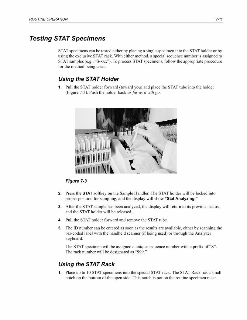
ROUTINE OPERATION 7-11
Testing STAT Specimens
STAT specimens can be tested either by placing a single specimen into the STAT holder or by using the exclusive STAT rack. With either method, a special sequence number is assigned to STAT samples (e.g., “S-xxx”). To process STAT specimens, follow the appropriate procedure for the method being used.
Using the STAT Holder1. Pull the STAT holder forward (toward you) and place the STAT tube into the holder
(Figure 7-3). Push the holder back as far as it will go.
Figure 7-3
2. Press the STAT softkey on the Sample Handler. The STAT holder will be locked into proper position for sampling, and the display will show “Stat Analyzing.”
3. After the STAT sample has been analyzed, the display will return to its previous status, and the STAT holder will be released.
4. Pull the STAT holder forward and remove the STAT tube.
5. The ID number can be entered as soon as the results are available, either by scanning the bar-coded label with the handheld scanner (if being used) or through the Analyzer keyboard.
The STAT specimen will be assigned a unique sequence number with a prefix of “S”. The rack number will be designated as “999.”
Using the STAT Rack1. Place up to 10 STAT specimens into the special STAT rack. The STAT Rack has a small
notch on the bottom of the open side. This notch is not on the routine specimen racks.

7-12 CLINTEK ATLAS with Rack Sample Handler Operating Manual
2. Place the rack onto the right side of the Sample Handler. Please note the following:
• If the STAT rack is introduced during a run, analysis of the rack will not take place until all preceding racks are processed.
• If the circulation function is OFF, add the STAT rack in the same manner as a routine rack.
• If the circulation function is being used, with the Stop by “20Rack,” the STAT rack should be added before processing begins. Otherwise, the last rack will not be tested when the instrument stops processing and returns to Standby.
• If the circulation function is being used, with the Stop by “Marker”, add the STAT rack to the infeed as an additional rack anywhere before the Stop Marker. Only add the STAT rack when the racks in the Sample Handler are not moving.
The STAT specimens will be assigned a unique sequence number with a prefix of “S.” The STAT rack will be assigned the next incremental rack number.
Obtaining STAT Results1. As soon as all results and information are available for the STAT specimen and for all
previously analyzed specimens, the record is transmitted to the host computer or LIS and/or to the printer. The results are also displayed on the screen.
If the results meet the criteria specified for the sieve search, an asterisk (*) is displayed next to the Sequence number. If specimen IDs, visual color, and/or clarity were selected for use and have not been entered into the record or if an ERROR was reported for the clarity result, a screen is first displayed that requests entry of the missing information for the STAT specimen(s). This screen is identical to that described in Specimen Information‚ page 7-15. Refer to this section for complete information on entering the necessary information. When all information has been entered, the results are displayed.
2. Press CONTINUE when finished with the screen. The results for any additional STAT specimens will be displayed if they are available, or the display will return to the appropriate screen for the current operation.

ROUTINE OPERATION 7-13
Recovering from Rack Sample Handler Errors
If an error is detected by the Rack Sample Handler:
• all processing will stop, • an error message and number will be displayed, • the error alarm will sound, • and the far-right key will be lit in red. • An error number will also be displayed on the Analyzer screen.
Press the red-lit key (STOP) to silence the alarm. Determine the reason for the error, referring to Section 11 for specific information, and correct if possible.
To begin testing again1. Move all racks out of the sampling and circulation area (see Figure 1-4). Move the racks
in the same direction as occurs during instrument operation. If testing was not completed on a rack, replace it into the front position in the right side, so it will be the first rack to be tested.
2. Reset the starting sample number, if necessary (see Starting Sample Number‚ page 7-4). The CLINITEK ATLAS display will provide the rack and position number of the last tube for which processing was completed. Use this number to determine the starting number.
3. After noting the information provided, press CONTINUE. The display will return to the Standby Mode (Ready for Testing screen) or to the appropriate End of Run Review screen (explained next).

7-14 CLINTEK ATLAS with Rack Sample Handler Operating Manual
End of Run Review
If End of Run Review has been selected as ON through the Set Up Analyzer routine, a screen will be displayed to alert the operator that specimens exist for which there are no results.
Processing of the run is generally not stopped when errors occur that cause missing results (for example, inadequate sample volume or inadequate dispense of sample onto a reagent pad). Instead, the specimen positions are displayed at the end of the run so that corrective action can be taken before proceeding The run will be terminated, however, if more than 44 specimens needing review have accumulated.
If there are results that meet the sieve search criteria or if additional data entry is required, different information will be displayed:
• For example, if specimen ID numbers were selected for use (through the Set Up Analyzer routine), any tube positions for which this information is missing will be displayed.
• If all samples were properly tested, specimen information entered, and results stored, the display will show all tube positions for which the results met the sieve criteria that were established through the Set Up Analyzer routine.
One or more screens, or none at all, may be displayed, depending upon the status of the results and the selections made during the Set Up Analyzer routine. STATs are not included, since STAT results are displayed immediately.
NOTE: If Specimen ID numbers are not being used, the Sequence Number will be displayed instead of the Specimen ID in the End of Run Review.

ROUTINE OPERATION 7-15
Error Conditions
The Error Condition screen applies only to samples with ID, color, and clarity entries. It is displayed if there are rack/tube positions for which no results are available because of an error condition.
The error condition that occurred is displayed next to the tube position and specimen ID, if available. Four possible error conditions may be displayed. If any of these errors occur during a run, results will not be available for the specimen on which the error occurred. The run is terminated only if a Pad Dispense Error is detected on three consecutive strips. The possible errors are:
Pad Dispense Error: displayed if the instrument detects that an inadequate volume of sample was dispensed.
Low Sample Volume: displayed if the instrument detects an inadequate specimen level in the sample tube at the specific tube position. Each tube should contain at least 2 mL of specimen to ensure adequate volume for pipetting. Non ionic solutions, such as distilled and deionized water, are not detected by the pipette.
Analyzer Cycle Error: displayed if an optical error is detected while reading the strip.
Optical Problem Detected: displayed if an optical error is detected during calculation of the result.
There are three possible softkey options on the Error Condition screen. Two of these are displayed only as required by the specific screen being displayed:
NEXT: indicates there are more tube positions, or there are additional rack numbers on which an error occurred. Pressing this softkey changes the display to the next group of up to four tube positions. This option is displayed only when there are additional screens to be displayed.
PREVIOUS: similarly, indicates there are lower numbered tube positions or rack numbers to be displayed. Pressing this softkey changes the display to the previous group of tube positions. This option will not be displayed when the first group of tube positions is displayed.
CONTINUE: changes the display to the next screen in the End of Run Review (see Sieve Lists‚ page 7-18) or returns the display to the Ready for Testing screen if there are no specimens for which the results meet the sieve criteria.
1. Press NEXT to display additional (higher-numbered) tube positions or rack numbers. Press PREVIOUS to display earlier screens. Record the rack/tube positions and specimen IDs so these specimens can be rerun.
2. Press CONTINUE to continue the End of Run Review.
Specimen Information
This screen allows manual entry of specimen IDs or visual color or clarity.

7-16 CLINTEK ATLAS with Rack Sample Handler Operating Manual
If an error occurred during the instrumental determination of clarity, you will also be given the opportunity to visually determine the clarity and enter it through these screens.
In addition, the display includes the rack/tube position and ID number, if available, of any record for which results are not available because of an error condition. The error (“Low Sample Volume,” “Pad Dispense Error,” “Analyzer Cycle Error,” or “Optical Problem Detected”) is displayed where the color and clarity are normally displayed. For additional information on these errors, refer to Error Conditions‚ page 7-15.
The arrow is initially positioned on the first tube position listed, and the cursor is located at the first field that requires an entry. The instructions given below assume that all three fields require entries (tube specimen ID, color, and clarity).
1. Enter the specimen ID number (up to 13 alphanumeric characters), using the Analyzer keyboard (or, if applicable, with the handheld bar code scanner). To enter the ID using the keyboard, proceed as follows:
• Press the appropriate numeric keys for a numeric entry.• If an alphabetic entry is needed, press the softkey under the letter (or character) until
the appropriate letter is displayed at the cursor. The displayed letter (or character) will be accepted when any other key is pressed. However, if a second letter is required that uses the same softkey, press to accept the first letter and move the cursor one position to the right.
• If a space is needed, press the softkey under the displayed symbol “ ”. This symbol will be shown above the cursor until it is accepted (by pressing or another key). Then a space will appear on the data entry line.
• If an error is made, press to erase the previously entered character on the display. If there are no characters remaining, pressing will move the cursor to the previous field that required an entry.
• Press when the ID has been correctly entered. The cursor moves to the Color field.
2. The Color field initially shows the default color of YEL (Yellow). When the cursor is positioned in this field, the screen changes to display the various Color options.
• If the color shown is accurate, press to accept the description and move to the Clarity field.
• For a different color description, press the appropriate numeric key. • For no color entry, press the NO ENTRY softkey for a blank entry. The cursor will
move to the Clarity field. • If an error was made in the entry, press to return the cursor to the previous field (in
this example, the Color field that was just completed).
3. The Clarity field shows the default clarity of CLR (Clear) unless an ERROR occurred. When the cursor is positioned in this field, the screen changes to display the various Clarity options.
• If the clarity shown is accurate, press to accept the description and move to the next line (Specimen ID of the next tube position).

ROUTINE OPERATION 7-17
• For a different clarity description, press the appropriate numeric key. • For no clarity entry, press the NO ENTRY softkey for a blank entry. In either case, the
cursor will move to the first field of the next line that requires entry of the specimen ID, color, and/or clarity.
• If an error was made in the entry, pressing returns the cursor to the previous field (in this example, the Clarity field that was just completed).
4. Repeat Steps 1 to 3 above, as necessary, for each line on the display. As the bottom line of the display is completed, the display will scroll to show the next tube position.
5. When all required information has been entered, the display will continue to the next screen in the End of Run Review.

7-18 CLINTEK ATLAS with Rack Sample Handler Operating Manual
Sieve Lists
If criteria were selected for either sieve (Confirmatory and Microscopics) through the Set Up Analyzer routine, any specimens that meet the criteria will be displayed on the appropriate Sieve List screen. (Version 7.11 or higher)
STATs are not included in the display, since STAT results are displayed immediately. If a STAT meets the criteria of either sieve, an asterisk (*) is displayed next to the Sequence number.
Manually entered color and clarity are not included in the sieve search.
If any samples meet the Confirmatory criteria, the Confirmatory sieve list is displayed. Each rack is listed separately. After all Confirmatory screens are displayed, the Microscopics sieve list is displayed
There are four available softkeys with either screen:
DETAIL: displays the result for one specimen at a time.
CRITERIA: displays the sieve criteria that are being used, as specified through the Set Up Analyzer routine.
PRINT: prints the displayed screen. This softkey is displayed only if a printer was selected through the Set Up Analyzer routine.
CONTINUE: changes the display to the next rack or to the first screen of the Microscopics sieve list. If all racks of both sieve lists have been displayed, pressing CONTINUE returns the display to the Standby Mode (Ready for Testing Screen).
1. Press PRINT to print the displayed screen.
2. Press CRITERIA to display the sieve criteria. The sieve criteria that were specified in the Set Up Analyzer routine are displayed. If a specimen has abnormal results for one or more of the listed analytes, it will be flagged by the sieve for display during this portion of the End of Run Review.
NOTE: To change the criteria, you must re-enter the Set Up Analyzer routine. This will clear all routine, STAT, and control results in memory. Therefore, do NOT change the criteria until all records have been printed and/or transmitted to a host computer or LIS.
3. Press DETAIL to display the results for each of the listed tube locations. See Detail Screen below.
4. Press CONTINUE when finished. The display will show the next rack of the current sieve list. When all Confirmatory List screens have been displayed, the first screen of the Microscopics List is displayed.
5. When all screens have been displayed, press CONTINUE to return the instrument to the Ready for Testing screen (Standby Mode).

ROUTINE OPERATION 7-19
Detail Screen
If the DETAIL softkey is pressed from either sieve list screen, the results for each of the listed tube positions are displayed, one set at a time.
The Detail screen provides the following information for each set of results displayed:
Tray/Tube: the sequential rack number and tube position of the specimen being displayed.
Test Type: the type of Analyze Mode that was performed (Routine).
Seq: the sequential number of the test being displayed.
Date and Time: the date and time at which the specimen was aspirated for testing.
ID: the specimen identification number, if IDs are being used.
There are also four possible softkey options on the Detail screen. Each is displayed only as required by the specific screen being displayed:
NEXT: indicates there are additional records (with a higher sequence number) that meet the sieve criteria. Pressing this softkey changes the display to the next record. This option is displayed only when there are additional records (with higher sequence numbers) to be displayed.
PREVIOUS: indicates there are previously displayed records (with a lower sequence number) that meet the sieve criteria. Pressing this softkey changes the display to the previous record. This option is not displayed when the first record is displayed.
PRINT: allows printing of the displayed record or of all records that meet the sieve criteria. This softkey is displayed only if a printer has been selected through the Set Up Analyzer routine.
CONTINUE: returns the display to appropriate sieve list screen.
1. Press NEXT and PREVIOUS as needed to review the records.
2. Press PRINT if you want to print. The softkey options at the bottom of the screen will change to display “THIS REC.” and “ALL REC.” The latter softkey is displayed only if there is more than one record that meets the sieve criteria. Press THIS REC. to print the displayed record only. Press ALL REC. to print all the records that meet the sieve criteria.
3. Press CONTINUE when you have finished reviewing the records. The display returns to the appropriate sieve list screen.

7-20 CLINTEK ATLAS with Rack Sample Handler Operating Manual
Disposal of System Waste and Supplies
Laws and regulations enacted to protect the environment and to encourage resource conservation require the disposal of hazardous and biohazardous wastes in a specified manner. Some of the wastes from the CLINTEK ATLAS Analyzer can be classified as hazardous or biohazardous wastes. It is essential that the laboratory take appropriate steps to determine the laws and regulations applicable to their disposal and to effect compliance. If it is necessary to sample instrument wastes and effluent in order to evaluate compliance with applicable regulations, the laboratory should contact a local licensed biohazardous waste disposal firm for assistance.
Human specimens, control materials, and all reagents, should also be handled and disposed of in accordance with the prevailing regulations and guidelines of agencies with jurisdiction over the laboratory. Refer to the product label and to Material Safety Data Sheets for details concerning any special precautions related to the handling of ATLAS Reagents, Calibrators, and Controls. Material Safety Data Sheets are available from Siemens Diagnostics.

8 RECALLING AND DELETING RESULTS
Results can be recalled to the display screen or deleted from memory whenever the instrument is not processing samples.
Press 1 from the Main Menu to display the Recall/Delete results menu. The following options are available:
1. Routine Test Results2. STAT Test Results3. Control Test Results4. Last Run Test Results5. Delete Results
Recalling Results1. Select one of the four types of results to recall from the Recall/Delete Results menu (see
above for choices).
The next screen (Recall Results By) shows another list of menu options to further define which results you want displayed. The choices available are dependent on the type of result chosen for recall.
If Routine Test Results or STAT Test Results was chosen, the options are:
If Control Test Results was chosen, the options are:
If Last Run Test Results was chosen, the options are:
• Sequence Number• Specimen ID• Date• Abnormals
• Confirmatory Sieve (version 7.11 or higher)• Microscopics Sieve (version 7.11 or higher)• All Results
• Sequence Number• Specimen ID• Lot ID
• Date• All Results
• Abnormals• Confirmatory Sieve
• Microscopics Sieve• All Results

8-2 CLINTEK ATLAS with Rack Sample Handler Operating Manual
2. Select an option from the Recall Results By menu.
• If Sequence Number, Specimen ID, Lot ID, or Date is selected, an additional screen is displayed for additional definition of the option.
• If Abnormals, Confirmatory Sieve, Microscopic Sieve, or All Results is selected, there are no further screens displayed and the first result is displayed.
Recall Results By Sequence Number
If Sequence Number was selected, the SEQ # selection screen will be displayed. The SEQ # selection screen is nearly identical for selecting Routine, STAT, or Control results by sequence number. The only difference is the prefix number.
• For Routine results, the prefix number must be entered if the Results Format selected is CT200+ or ASTM (see Set Sequence Number‚ page 3-2).
• For STAT and Control results, the prefix of “S” or “C,” respectively, is automatically displayed (or “ST” or “CN” if the Results Format is CT A2000).
There are two ways in which records can be selected by sequence number:
Starting SEQ #: You can select an entire group of records by entering the lowest SEQ # of the group you want to recall. When only the lowest SEQ # is entered, all records equal to or greater than the SEQ # entered, all having the same prefix number, are selected.
1. Enter the number and press .
2. Press SEARCH to display the first result. Or, re-enter the SEQ # if an error was made.
Starting and Ending SEQ #: You can select a specific group of records by entering the lowest and highest SEQ #s of the group you want to recall. This group of records can include records from more than one prefix group. The records selected will include both of the SEQ #s entered and all SEQ #s between.
1. Enter the lowest number and press , then enter the highest number and press .
2. If you want to recall only a single record, enter the same number for both Starting and Ending SEQ #.
3. Press SEARCH to display the first result, or re-enter the first SEQ # if an error was made.

RECALLING AND DELETING RESULTS 8-3
Recall Results By Specimen ID
If Specimen ID was selected, the Specimen ID selection screen will be displayed. Through the ID selection screen, a single record, or a group of records with a common beginning set of digits, can be recalled using the specimen ID number.
1. To select one specific record, enter the complete specimen ID of the record to recall, using the numeric keypads and/or the alphabetic/character softkeys. If applicable, the handheld bar code scanner could also be used to enter the number from the bar-coded label on the tube.
2. To select a group of records with a common beginning set of digits, enter only those digits that all the records in the group have in common.
3. Press when the number is correctly entered. The screen will display the record(s) that correspond to the entered ID number. For example, entering the digits “956” would recall every record for which the first three digits are “956.”
Recall Results By Lot ID
If Lot ID was selected, the Lot ID selection screen will be displayed. Control records can be recalled by the Lot ID number, a process that is identical to recalling patient records by specimen ID number.
1. Enter the lot ID number of the control records to recall, using the numeric keypads and/or the alphabetic/character softkeys.
2. Press when the number is correctly entered. The screen will then display the most recent record that corresponds to the entered lot ID number.
Recall Results By Date
If Date was selected, the Date selection screen is displayed.
1. Enter the Starting Date.
2. Enter the Ending Date.
3. Press SEARCH to display the first result. Re-enter the dates if an error was made.

8-4 CLINTEK ATLAS with Rack Sample Handler Operating Manual
Results Screen
The first record that meets the specified criteria is displayed on the Results Screen. If more than one record has the same Sequence #, Specimen ID, or Lot ID, the most recent record is displayed first.
The Results screen gives numerous pieces of information:
Tray/Tube: the tray number and tube position of the record being displayed.
Test Type: the type of Analyze Mode that was used for this specimen. The possible options are Routine, STAT, and Control.
Seq: the sequential number that was assigned to the record. If there are results in the record that meet the sieve criteria, an asterisk (*) is displayed prior to the Sequence number.
Time and Date: the date and time at which the specimen was aspirated for testing.
ID: the specimen identification number if IDs are being used.
In addition, there are four softkeys with the following functions:
NEXT: recalls the next record in the list that meets the specified criteria. If there are no additional records, this softkey is not displayed.
PREVIOUS: reverses the direction in which the records are recalled, moving backwards through the list of those that meet the specified criteria. If the first record is being displayed, this softkey is not displayed.
SEND/PRINTER/COMPUTER: allows for transmission of the displayed record or of all recalled records to a printer or host computer/LIS. This softkey is displayed as SEND if both a printer and computer interface have been selected through the Set Up Analyzer routine. If only a printer or computer interface has been selected, the softkey is displayed as PRINTER or COMPUTER, respectively.
DONE: returns the display to the menu screen from which the results were recalled (i.e., Routine, STAT, Controls, Last Run).
1. Press NEXT or PREVIOUS as needed to cycle through the specimen result screens.
2. If you want to print or transmit one or more records (and the softkey is available), press SEND, PRINTER, or COMPUTER, whichever is being displayed.
The softkey options change to THIS REC. and ALL REC.
• Press THIS REC. to send the displayed record only.• Press ALL REC. to send all the recalled records. If PRINTER or COMPUTER was pressed, the record(s) will be transmitted to the appropriate device.
If SEND was pressed, the softkeys will change again to specify the destination of the transmission. Press COMPUTER to send the recalled record(s) to a host computer or LIS or press PRINTER to print the record(s).

RECALLING AND DELETING RESULTS 8-5
3. Press DONE when all records have been reviewed, printed, and/or transmitted. The display will return to the menu screen from which the results were recalled.
Deleting Results
You can also delete results that are stored in memory from the Recall / Delete menu. You can delete all routine and STAT results, all control and calibrator results, or both.
1. Press 5. Delete Results from the Recall/Delete menu.
2. Select an option by pressing the appropriate numeric key:
1. Delete Routine and STAT Results2. Delete Control and Calibration Results3. Delete ALL Results
NOTE: If the selected results have not been sent to a computer or printer, or if a load list is in memory, a warning will be displayed and you will not be allowed to delete the results. Press CONTINUE to return to the Delete Results menu.
3. Confirm your decision at the next screen.
• If you do NOT want to delete results, press CANCEL and the display will return to the Delete Results menu without deleting any results.
• If you are sure you want to delete the selected results, press DELETE and they will be erased. The process may take several seconds to accomplish, depending upon the number of results being deleted.
4. After the results have been deleted, press to return to the Recall/Delete screen.

8-6 CLINTEK ATLAS with Rack Sample Handler Operating Manual

9 MAINTENANCE
General Information
The CLINITEK ATLAS Automated Urine Chemistry Analyzer requires minimal maintenance. Handle the instrument with care. Avoid prolonged exposure to excessive humidity or extreme temperatures. Keep the exterior of the instrument, including the display and keyboard, free of dust by wiping periodically with a damp cloth and mild detergent. Do not use any type of solvent on any part of the instrument. Do not use any kind of spray cleaners, since the aerosol may enter and damage the optical system.
The instrument should be left on at all times. The SG well is automatically rehydrated every 15 minutes to prevent drying of the fiber optic. The instrument doors should be kept closed at all times (except when required by the procedure being performed) to prevent dust and debris from entering the readhead area and to ensure proper rehydration of the SG well.
If the instrument is going to be idle for several days, the waste bottle should be emptied prior to the idle period to prevent excessive bacterial growth in the bottle. If the instrument has been off for longer than one hour, prime the pump (by pressing 5 from the Main Menu). Then leave the instrument ON for at least one hour (to rehydrate the SG well) before re-assuming operation.
NOTE: For your convenience, a maintenance log template is provided at the end of this section. Copy this log template every month, and use it as a record of the maintenance of your CLINITEK ATLAS.
BIOHAZARDWear personal protective equipment. Use universal precautions. Refer to Appendix C, Protecting Yourself from Biohazards for recommended precautions when working with biohazardous materials.

9-2 CLINTEK ATLAS with Rack Sample Handler Operating Manual
Daily Maintenance
Sample Handler/Racks
Each day, the sample handler area should be cleaned with a damp cloth and mild detergent to remove any splatters. Clean the specimen racks using a mild detergent and rinse with clear water. Dry carefully with a soft, lint-free cloth.
SG Well
The SG well must be cleaned once a day or after loading a new reagent roll, whichever is more frequent. The procedure is performed automatically by the instrument and takes about 3 minutes.
• The display will prompt for SG well cleaning when 24 hours have elapsed since the last cleaning and again after a new reagent roll is loaded. The instrument will not begin processing until the cleaning procedure has been performed.
The cycle is started by pressing the softkey under the option CLEAN SG WELL that is displayed when the “Clean SG Well” warning is displayed.
• The SG well is also cleaned as part of the calibration procedure, regardless of whether calibration is requested through the Analyze Mode or is performed after a new reagent roll is loaded.
• In addition, the cleaning cycle can be requested at any time by pressing 6 from the Main Menu. The display provides the instructions needed.
If the SG well needs to be cleaned at any time other than during calibration, the STAT holder must be used, as described in the following steps.
1. Press 6 from the Main Menu or press the CLEAN SG WELL softkey.
2. Pour at least 2 mL of household bleach (5.25% sodium hypochlorite) into an appropriately labeled sample tube. This bleach solution is used to clean the SG well.
3. Pull the STAT holder forward (toward you) and place the tube of bleach into the holder. Push the holder back as far as it will go.
4. Press BEGIN on the Analyzer.
5. When the cleaning cycle is complete, the display returns to the Main Menu. Pull the STAT holder forward and remove the tube of bleach.
CAUTIONUse of bleach stronger than 5.25% sodium hypochlorite will damage the SG sensor. Therefore, check the concentration of sodium hypochlorite in the bleach being used. If it is higher than 5.25%, the bleach must be diluted with distilled water. For example, if the bleach is 6% sodium hypochlorite (e.g., Ultra Clorox), add 0.75 mL of water to 5 mL of the 6% bleach and mix gently.

MAINTENANCE 9-3
Periodic Maintenance
When Loading New Reagent Roll
Perform the following three procedures each time the reagent roll is replaced (at least once every 14 days).
• Clean the stationary rod sleeve (part “F” on the loading diagram) and the tension Sprocket (part “E” on the loading diagram). See Section 5, LOADING THE REAGENT ROLL for instructions.
• Check the syringe to ensure that it is tightly secured (Figure 9-1). The syringe tightens in a counterclockwise direction and should be just finger tight. Gently attempt to tighten the syringe. Tighten it only if it rotates freely.
• Clean the readhead assembly and platform, as described next.
Figure 9-1

9-4 CLINTEK ATLAS with Rack Sample Handler Operating Manual
Readhead Assembly and Platform
This procedure should be performed each time the reagent roll is replaced.
1. Remove the used reagent roll.
2. Turn the two shorter screws located at the front and back of the readhead assembly. Keep one hand underneath the platform (Figure 9-2). The platform will drop down and can be removed when these screws are sufficiently loosened.
Figure 9-2
3. Clean the platform with a soft cloth dampened with water. Dry it with a soft cloth.

MAINTENANCE 9-5
4. Clean the underside of the readhead assembly by gently wiping with a damp paper towel (Figure 9-3). Continue cleaning the readhead until there is no sign of dirty streaking on the towel.
Figure 9-3
5. Replace the platform by sliding the small pins on the platform into the opening on the readhead. Hold the platform in place by pressing up from underneath until the two shorter screws have been retightened. The screws have a slight spring tension. Press down slightly on each screw as you begin to tighten it.
Readhead Sockets
The sockets in the readhead assembly into which the optics fit can become contaminated with dried urine from the reagent strips. If this occurs, the optical sensitivity of the instrument will be affected. Therefore, these sockets should be cleaned every four months or after every 100 Reagent Paks (50,000 tests), whichever occurs first. The procedure is simple and requires only about ten minutes to complete.
Materials Required• Cleaning Brush• Portable Lamp or Small Flashlight• Distilled Water• Isopropyl Alcohol• Lens Paper

9-6 CLINTEK ATLAS with Rack Sample Handler Operating Manual
Procedure1. Unload the used Reagent Pak.
2. Turn the instrument power off and remove the power cord from the receptacle.
3. Clean the readhead assembly and platform, as instructed earlier in this section. Do not replace the platform.
4. Clean the rotating spool and the stationary rod sleeve (parts “E” and “F” on the loading diagram found on the inside of the reagent compartment door and at the end of Section 5 in this manual).
5. Loosen the two thumb screws on the side of the readhead cover, then lift the cover off (Figure 9-4).
Figure 9-4
6. Arrange the portable lamp or flashlight so that good lighting is provided inside the instrument. You should be able to clearly see all the sockets and optics on the readhead assembly.
7. Completely loosen the two taller knurled head screws, located at the front and back of the readhead assembly.
1 Thumbscrews

MAINTENANCE 9-7
8. Holding onto the screws, lift the inner block of the assembly, which contains the optics, from the bottom block (Figure 9-5). Be sure to lift the inner block just enough to expose the empty sockets on the bottom block, without bending or damaging the optics.
Figure 9-5
9. Carefully rest the edge of the inner block on the rotating spool immediately to the right of the readhead. Be sure the optics themselves (on the bottom of the block) are not touching the spool.

9-8 CLINTEK ATLAS with Rack Sample Handler Operating Manual
10. Clean each socket in the bottom block using the circular end of the cleaning brush (included in the Supply Kit) by moving the brush in and out of the hole a couple of times (Figure 9-6). There are four rows of sockets. All should be cleaned.
Figure 9-6
11. After all sockets have been cleaned, gently wipe both the under and top sides of the bottom block, using a clean paper towel dampened with water. Be sure to remove any residue or dust that has accumulated from the cleaning procedure.
12. Carefully inspect the underside of the inner block for any film or precipitation on the bottom of the fiber optics. Each optic should appear as a shiny frosted circle inside a dark circle.
Under normal conditions, the fiber optics do not come into contact with the specimens or reagent pads, so they should not be contaminated. However, if any of the optics are dirty, clean them all as follows:
a. Lightly dampen a piece of lens paper with distilled water and wipe gently along the bottom of the fiber optics on the underside of the inner block.
b. After the optics appear clean, dampen a clean piece of lens paper with isopropyl alcohol and again gently wipe the fiber optics to dry the surfaces.
13. Replace the inner block onto the bottom block of the readhead assembly and tighten the taller thumb screws.
14. Replace the platform by sliding the small pins on the platform into the opening on the readhead. Tighten the two shorter screws while holding the platform in place and pressing up from underneath. Press down slightly on each screw as you begin to tighten it.
15. Place the readhead cover over the optic bundles, fitting the two slots over the thumb screws. Press down firmly on the cover until it is level and tighten the thumb screws.

MAINTENANCE 9-9
16. Plug the power cord into the instrument receptacle and turn the instrument power on.
17. Load a new Reagent Pak (refer to Section 5, LOADING THE REAGENT ROLL) and recalibrate the instrument.
NOTE: If the instrument has been off for longer than one hour, prime the pump (by pressing 5 from the Main Menu). Then leave the instrument ON for at least one hour (to rehydrate the SG well) before re-assuming operation.
Tube and Rack Sensors
The Sample Handler contains several sensor windows that must be cleaned periodically to prevent rack jams and operating problems. These are shown in the diagram in Figure 9-7.
• The four small oval windows on the outside edges of the Sample Handler platform sense the rack movement.
• Two larger, square windows are located along the back wall, in the sampling area. One detects the presence of the Stop Marker. The other detects the presence of a rack at the sampling station.
• The tube detector is located at the back of the Sample Handler, under the reagent compartment. Its reflector window is located on the back side of the STAT holder.
• The bar code reader, if installed, also has an optic window that must be cleaned.
Once each month or whenever residue is observed on any of the optic windows, all should be cleaned as described below.

9-10 CLINTEK ATLAS with Rack Sample Handler Operating Manual
1. Dampen a long, cotton-tipped swab with water. Gently wipe each sensor (see Figure 9-7 for locations). Be sure not to leave any residue on the plastic surfaces.
NOTE: The tube detector window is located at the back of the Sample Handler, about 5 inches (13 cm) behind the sampling area. You can access the sensor by opening the left instrument door and reaching through from the side, under the reagent compartment.
2. Using a dry swab, carefully dry the surfaces.
Figure 9-7

MAINTENANCE 9-11
Checking for Leakage
Once each month, check the pipette for leaks. These could indicate the need to replace the pipette assembly or the valve.
1. Press 9. Analyzer Diagnostics from the Main Menu.
2. Enter the default password (entry code) of 2633, or your personalized code to access the Diagnostics menu.
3. Press 1 for Replace Hardware.
4. Press 1 for Replace Pipette.
The display will change to show the first of five screens of instructions for the replacement of the pipette assembly. Only the first screen will be used for this procedure. The remainder of the screens will be bypassed.
5. Remove any racks that are in the sampling area.
6. Press the softkey option of MOVE PIPETTE. The pipette will be moved forward so that it is accessible. After all movement has ceased, open both the instrument doors.
7. Place a paper towel or filter paper under the pipette (but not touching the tip). Leave the instrument in this position for two minutes.
8. Check the paper towel for any drips from the pipette tip. If the towel is dry, continue as instructed in Step 9. below.
If any moisture is observed, tighten the finger nut on the right side of the valve by turning it 1/4 to 1/2 turn. See Replacing the Pipette Assembly‚ page 12-7.
Place a dry paper towel or filter paper under the pipette. Observe the pipette for another two minutes. If the leakage continues to be seen, the pipette assembly and/or the valve may need to be replaced. Call your local technical service support provider to determine the next step. See Section 12, MINOR REPLACEMENT AND ADJUSTMENTS, for the replacement procedures.
9. Close the instrument doors and press the CONTINUE softkey.
10. Press POSITION PIPETTE at the next display and press DONE when the final display is shown. The display will return to the Replace Hardware menu.
11. Press as needed to return to the Main Menu or the Standby Mode.

9-12 CLINTEK ATLAS with Rack Sample Handler Operating Manual
Cleaning the Rack Movement Pawls
If urine spills are allowed to dry on the rack movement pawls, the pawls may stick and not function properly. If this happens, the racks may move in an uneven manner. The pawl that is sticking needs to be cleaned.
1. Remove all racks from the Sample Handler, then press ANALYZE and ROUTINE.
2. Watch the pawls as they move forward and backward along the pairs of slots in the loading and unloading areas.
You should be able to see each white pawl rotated up and moving through the slot. If one is not operating the way it should, the pivot mechanism may need to be cleaned.
3. When the pawls are about midway across the loading and unloading areas, turn off the power to the Analyzer or unplug the Sample Handler power cord from its outlet. Use an unbent paper clip or other small object to catch the dirty pawl and raise it to the upright position.
4. Carefully wet the pivot with one or two drops of distilled or deionized water (Figure 9-8) and rotate the pawl up and down. If needed, add another drop of water and continue rotating the pawl until it moves freely.
NOTE: Add water very sparingly!
Figure 9-8
5. Wipe off any excess water from the platform, then turn on the Analyzer or plug the Sample Handler power cord into its electrical outlet.
MAINTENANCE 9-13
Disinfection of the Instrument
Disinfection may be required on several parts of the instrument, such as the Sample Handler, reagent strip platform, displays and keyboards, detector windows, and specimen racks.
Several solutions are acceptable for use on the instrument. Cidex and Theracide are commercially available products that can safely be used when prepared and used according to the labeling accompanying the product. Isopropanol is also acceptable (a 70% to 85% solution is more effective than 100%).
Wet the item to be disinfected with the solution. Wait the appropriate length of time for the solution used (as noted by the manufacturer), then wipe off with water and dry.
NOTE: Do not use aerosol products, as the aerosol may enter and damage the optical system. Bleach should also not be used, since it can adversely affect several parts of the instrument, especially the readhead platform and the bar code reader.

9-14 CLINTEK ATLAS with Rack Sample Handler Operating Manual

Maintenance Log - CLINITEK ATLAS® with Rack Sample Handler
System Serial Number ______________________ Month ________ Year ________
1 2 3 4 5 6 7 8 9 10 11 12 13 14 15 16 17 18 19 20 21 22 23 24 25 26 27 28 29 30 31
Operator’s InitialsDaily Maintenance ActivityClean Sample Handler
Clean Sample Tray
Clean SG Well
When Loading ReagentsClean Stationary Rod Sleeve (F)
Clean Platform
Clean Underside of Readhead
Check Syringe Fitting
MonthlyClean Detector Windows
Check Pipette for Leaking
Every Four MonthsClean Readhead Sockets
Clean Rack Movement Pawls
As NeededReplace Fuse
Replace Lamp
Replace Pipette
Replace Syringe
Lubricate Syringe Lead Screw
Replace the Rinse Tubing


10 TROUBLESHOOTING
Troubleshooting — General Information
As with all complex instruments, errors may occur with the CLINITEK ATLAS Automated Urine Chemistry Analyzer. Some errors require the instrument to adjust its operations, after which time processing can continue. Other errors require intervention by the operator. Error messages may be displayed on either the Analyzer screen or on the Rack Sample Handler screen.
The display screen on the Analyzer will show a brief explanation of the problem detected and detailed information on the action needed to correct the problem. In some cases, a service code will also be displayed in the upper left corner of the screen, which you may be instructed to record.
One or more softkey options will also be displayed, with appropriate information for each. If the explanation for an error requires more than one screen to display, MORE will be displayed as a softkey option. Read the screen information, then press MORE to display the next screen. Softkey options that are specific for correcting the error will be displayed at the final screen.
Detailed information on some of the most common error messages are available later in this section.
Error numbers and messages specific to the Rack Sample Handler may be displayed on the Sample Handler screen. The error numbers alert the operator of an operational or instrument problem. The Troubleshooting Chart later in this section lists the various errors, along with probable causes and recommended remedies.
An error message and number will also be displayed on the Analyzer screen. The error numbers will generally not be the same as those shown on the Sample Handler screen. Refer to the end of the Troubleshooting Chart for information on the Analyzer screens.
When instrument processing was stopped because of the detection of an error, a screen will be displayed prior to returning to the Standby Mode. Press CONTINUE to return to the Standby Mode.

10-2 CLINTEK ATLAS with Rack Sample Handler Operating Manual
Warnings in the Standby Mode (Ready for Testing Screen)
A variety of warnings may be displayed in the Standby Mode (Ready for Testing screen) on the Analyzer. These warnings inform the user of the status of, for example, the reagents (not present, low quantity, expired use life), memory, and calibration.
Press ANALYZE to display further information on the warning.
As with the Analyzer screen, several different messages may be displayed on the Standby screen of the Rack Sample Handler. Refer to Section 7, ROUTINE OPERATION, for complete information on these messages.
When to call for assistance• If the error message continues to be displayed after performing the steps described as
“Action Needed” on the Analyzer Screen.
• If the problem cannot be corrected through the Analyzer Diagnostics routine (see Section 11, ANALYZER DIAGNOSTICS) or through use of the troubleshooting information contained in this section.
• If additional assistance is required concerning an instrument problem.
• If the problem cannot be isolated or is beyond the scope of this manual.
Before calling for assistance, complete the Preservice Checklist‚ page 13-2.
Then contact your local technical support provider for information and assistance.

TROUBLESHOOTING 10-3
Messages Displayed on the Sample Handler ScreenError No./Message Probable Cause Remedy#01 ROM Checksum Error #02 RAM Chip Error#03 Parameter Loss#04 Hardware Error (nn)
Instrument malfunction. Turn off the power to the Analyzer, wait 15 seconds, then turn it back on. If the error repeats, record the error number and contact your local technical service provider.
#08 Calibration Error X An error was detected at the beginning of the Calibration Analyze Mode.
If X is:
1—The tubes were not in consecutive order
1—Place the tubes in the correct positions, as shown on the display screen.
2—Fewer than five tubes were detected.
2—Be sure all five tubes are in place.
3—No rack was detected. 3—Do not press CONTINUE from the Calibration screen until the rack is in place.
#09 Control Error X An error was detected at the beginning of the Control Analyze Mode.
If X is:
1—The tubes were not in consecutive order.
1—Place the control tubes in consecutive position, beginning with position #1.
2—No rack was detected. 2—Be sure the specimen rack is in place before pressing ANALYZE, CONTROL.
#12 Clean Error A tube was not detected in the STAT holder when the SG Well Clean Cycle was started.
Be sure the tube of full-strength bleach is in place in the STAT holder, and the holder pushed as far back as it will go, before requesting the Clean Cycle.
#13 Rack area full The left (outfeed) side of the Sample Handler contains 10 racks. This error occurs only when rack circulation is set to “OFF.”
Remove the racks from the left side.

10-4 CLINTEK ATLAS with Rack Sample Handler Operating Manual
#14 Rack Jam nn A rack jam has been detected. The number (“nn”) describes the area in which the error has occurred:1–2: Infeed area (right side)3–6: Sampling area (back)7–8: Outfeed area (left side)9–10: Circulation area (front)
Attempt to clear the jam. Clean the base of the Sample Handler if it is wet or dirty. Attempt to begin processing again. If the error repeats, record the number (“nn”) and contact your local technical service provider.
#16 -Poor Bar Code Labels The bar code reader was unable to read the bar codes because the format is different from that selected through the User Setup Mode.
If more than one format of bar code is being used, select Auto as the Bar Code Type in the User Setup Mode.
#17 Bar Code Error Limit The number of bar-coded labels that were unable to be read has reached the number specified through the User Setup Mode.
Record the rack and position numbers of the tubes for which errors are recorded. The ID number for these tubes can be entered during the End of Run Review either using the optional handheld bar code scanner or through the Analyzer keyboard
#19 Rack Remained 1—A rack still remains on the right side when the number of racks tested has reached the number stored in memory. Occurs only if circulation mode is “ON” and stop is by “20Rack.”
1—A rack may have been added to the batch after processing was started and the number of racks present has been stored in memory. Begin testing again to complete the run. Be sure all racks for the run are in place before processing begins.
2—The Sample Handler was unable to feed a rack through the sampling area in the allowed time. May be caused by the presence of an unreadable bar code label on a tube that is preceded by numerous (8 to 9) empty tube positions.
2—Begin testing again to complete the run. Be sure to use bar-coded labels that are within the specifications required by the bar code reader.
#20 Communi. Timeout Communication between the Analyzer and Sample Handler is not occurring as it should.
Turn the Analyzer off, wait 15 seconds, then turn it back on. If the error repeats, contact your local technical service provider.
Error No./Message Probable Cause Remedy

TROUBLESHOOTING 10-5
Messages Displayed on the Analyzer Screen
#21 Motor Error X Instrument malfunction. Record the entire error number and contact your local technical service provider.
#22 Can’t Start X The instrument is unable to complete the initialization. If X is:1—there is a rack in the circulation area across the front of the Sample Handler.2—there are racks on the right (infeed) side of the Sample Handler.
Remove all racks from the Sample Handler before turning the power on. Turn the power off, wait 15 seconds, then turn it back on. If the error repeats, record the entire error number and contact your local technical service provider.
Error Number Probable Cause Remedy100 The Sample Handler is not
at the Standby screen or is not ready to begin analyzing.
Press ESC or CONT as needed to return the Sample Handler to the Standby screen.
All other Refer to the Sample Handler screen for a description of the problem.
Refer to the Troubleshooting Chart—numbers Sample Handler for complete information.
Error No./Message Probable Cause Remedy

10-6 CLINTEK ATLAS with Rack Sample Handler Operating Manual

11 ANALYZER DIAGNOSTICS
The CLINITEK ATLAS instrument software includes an Analyzer Diagnostics routine. Through this routine,
• several minor repairs and adjustments can be made,• the Set Up Analyzer defaults can be restored, • the password changed, • and several aspects of the raw data can be displayed.
This data can help your local technical service provider determine the cause of an error or instrument problem.
Press 9 from the Main Menu to select Analyzer Diagnostics routine.
You will be prompted to enter the password. The instrument default code is 2633, or you can enter your individually selected password. After correct entry, the display will show the following options:
1. Replace Hardware2. Adjust Tube Detector3. Reset Analyzer Setup Defaults4. Display Rev. Level/Cycles/Password5. Display Calibration Data6. Display Test Data7. Display Sensor Status8. Test Display, Keypad, and Ports9. Install Shipping Lock
Option 2 is not available for selection when using the Rack Sample Handler.
Replace Hardware
Four different pieces of hardware can be replaced with the aid of this option. Complete information on performing these replacements (pipette, rinse tubing, syringe, and valve) are found in Section 12, MINOR REPLACEMENT AND ADJUSTMENTS.
Adjust Tube Detector
Tube detection is handled through the Rack Sample Handler software. This option is not available for selection.

11-2 CLINTEK ATLAS with Rack Sample Handler Operating Manual
Reset Analyzer Setup Defaults
When the CLINITEK ATLAS Analyzer is sent from the manufacturer, all options in the Set Up Analyzer routine are set to default values. These values can be restored, deleting most values that were changed through the Set Up Analyzer routine (see Section 4). However, settings for language will be saved.
1. Press 3 from the Diagnostics menu to select this option.
2. Press YES to reset all the values selected in the Set Up Analyzer routine to the defaults. All records in memory will also be deleted.
Press NO if you want to leave the changed values as they are, without restoring the defaults.
A screen will be displayed that requires a second YES response before restoring the defaults.
3. Press YES again to reset the default values. A softkey will then be displayed by which the instrument will restart to initialize the default settings.
Press NO if you want to leave the changed values as they are, without restoring the defaults.
NOTE: If default values are restored, the instrument must be recalibrated.
Display Rev. Level/Cycles/Password
Press 4 from the Diagnostics menu to display:
• the instrument Serial Number;• the revision level of the software that is installed in the instrument;• the ROM timestamp, which represents the date and time at which the software was
compiled;• the total cycle count (the total number of specimens, including controls and
calibrators, that have been tested in the lifetime of the instrument).
This screen also allows the customized (user-selected) password to be changed.
1. Press the softkey under PASSWORD to display the current user-selected password. If no customized password has been selected, asterisks are displayed instead. A softkey option of CHANGE is then displayed.
2. To change (or create) a customized password, press CHANGE.
As the new password is entered (a maximum of six numeric characters), asterisks are placed on the screen.
3. Press when the password has been entered. You will then be prompted again:
4. Re-enter the password, taking care to enter the same digits as previously. Then press .

ANALYZER DIAGNOSTICS 11-3
• If entered correctly twice, the new password is accepted. This password can now be used to enter the Set Up Analyzer and Analyzer Diagnostics routines. In addition, the default password (2633) can also be used. Press to return to the Diagnostics menu.
• If the two entries did not agree, the screen will display a message, indicating that the password has NOT been changed. Press to return to the Diagnostics menu and repeat the process, ensuring that you enter the password identically both times.
Display Calibration Data1. Press 5 from the Diagnostics menu to display the calculated calibration values from the
most recent calibration attempt (successful or failed).
One or more series of numbers will be displayed for each reagent test, as well as for clarity and the SG refractometer. If requested by your local technical service provider, these numbers may assist in determining the cause of an instrument problem.
If a printer was selected through the Set Up Analyzer routine, a softkey option of PRINT is displayed and the screen can be printed.
2. Press to return to the Diagnostics menu.
Display Test Data1. Press 6 from the Diagnostics menu to display the test data values that are computed from
the reflectance measurements taken from the most recent sample.
These values, including clarity and the refractive index value from the SG refractometer, are displayed even if the results from that specimen were rejected and the clinical values were displayed as “ERROR”. If requested by your local technical service provider, these numbers may assist in determining the cause of an instrument problem.
If a printer was selected through the Set Up Analyzer routine, a softkey option of PRINT is displayed and the screen can be printed.
2. Press to return to the Diagnostics menu.
Display Sensor Status
This option should be accessed only when directed by your local technical service provider.
The CLINITEK ATLAS Analyzer has numerous sensors that constantly monitor the status of the electronic components of the instrument.
1. Press 7 from the Diagnostics menu to view the status and responses of these sensors.
2. Press to return to the Diagnostics menu.

11-4 CLINTEK ATLAS with Rack Sample Handler Operating Manual
Test Display, Keypad, and Ports
Several aspects of the display, keypad, and interface ports can be tested through this option.
Press 8 from the Diagnostics menu to display the following options:
1. Serial Port Loop Back Test2. Serial Port Output Character Test3. Parallel Port Output Test4. Display Test5. Keypad Test
Serial Port Loop Back Test
This test allows the instrument to compare data that is transmitted from the serial port to that received by the same port. Either serial port can be tested.
1. Press 1.
2. Select the port to test (S1 or S2).
3. Obtain a loopback connector, either by making your own or by ordering from your local technical support provider (see Replacement Parts‚ page 13-7).
The connector is a serial 25-pin male connector on which pins 2 and 3 and pins 4 and 5 are connected. Using this connector, all data that is sent out from the serial port is received by the same port. The data is then displayed on the screen.
4. Attach the connector to the appropriate serial port (S1 or S2).
5. Press BEGIN to start the test.
The port will begin transmitting and receiving the ASCII character set (20H to 7EH). The display will constantly update several pieces of information:
RTS Status: the current status of the RTS (Request to Send) line. The options are HIGH and LOW.CTS Status: the current status of the CTS (Clear to Send) line. The options are HIGH and LOW.Bytes Sent: the total number of bytes sent.Error Count: incremented each time the number of bytes received does not equal the number sent.
6. Press the CLEAR ERRORS softkey at any time to reset the Error Count to 1.
7. The test continues until 99,999 bytes have been sent. Press the END TEST softkey to terminate before that time.
When the test is completed, or when END TEST is pressed, the display shows the bytes sent and the error count.
8. Record the two sets of numbers, if needed. Then press . The display will return to the Display,Keypad,Port menu.

ANALYZER DIAGNOSTICS 11-5
Serial Port Output Character Test
This test allows for a display of the actual data that is being transmitted from the serial port to a video terminal. If a keyboard is connected to the video terminal, characters from that keyboard can be sent to the instrument through the serial port and displayed on the instrument screen. Either serial port can be tested.
1. Press 2 to display softkey options of S1 and S2, along with the prompt “Select port to test.”
2. Select a port.
3. Connect a video terminal to the serial port, using a standard serial interface cable and the configuration shown on the screen display.
If the video terminal includes a keyboard, characters can be typed from that keyboard for display on the CLINITEK ATLAS screen.
4. When ready to start the test, press BEGIN.
The entire ASCII character set (20H to 7EH) is sent from the instrument through the serial port to the video terminal.
The RTS (Request to Send) line is held at HIGH.
5. Press keys on the video terminal keyboard. Each key is displayed on the instrument screen. Each character that is sent should be identical to the character received. The status of the CTS (Clear to Send) input is also displayed.
6. The test continues indefinitely, until the END TEST softkey is pressed. The display then returns to the Display,Keypad,Port menu.
Parallel Port Output Test1. Press 3.
2. Check that the printer has paper, and that the printer is turned on and on-line.
3. Press BEGIN, to transmit the printable ASCII character set (20H to 7EH) to the parallel port.
The lines will be formatted as: 9 leading spaces; 31 characters; <CR><LF>.
4. When the printout is complete, press to return the display to the Display,Keypad,Port menu.

11-6 CLINTEK ATLAS with Rack Sample Handler Operating Manual
Display Test
The display can be tested to ensure that all pixels (the lighted elements on the display) are being lit and turned off appropriately.
1. Press 4 from the Display,Keypad,Port menu.
2. Press BEGIN when ready to start the test.
3. The test will alternately display a screen filled with block characters and a screen with no pixels lit.
4. When you have determined which pixels, if any, are faulty, press any key. The display will return to the Display,Keypad,Port menu.
If there are numerous faulty pixels, or it they are located in critical areas, the display may need to be replaced. Contact your local technical service provider for further information.
Keypad Test
If there is a question as to whether a key on the instrument is functioning properly, the keypad can be tested for its response.
1. Press 5 from the Display,Keypad,Port menu. The Keypad Test screen is displayed.
2. Press various keys and view the results as follows:
• Each numeric key that is pressed should be displayed correctly. • The four softkeys will be displayed, from left to right, as “A” through “D”. • The STANDBY key will be displayed as . • The ENTER key ( ) will be displayed as . • When the BACKUP key is pressed, will be momentarily displayed, the test will be
ended, and the display will return to the Display,Keypad,Port menu.
3. Press to end the test and return to the Display,Keypad,Port menu.

ANALYZER DIAGNOSTICS 11-7
Return to Diagnostics Menu
Press when all tests have been completed to return the display to the Diagnostics menu.
Install Shipping Lock
If the instrument must be shipped, the pipette must be locked into place to protect it from damage. Your local technical service provider will prepare the instrument for shipping. At that time, option 9 will move the pipette into the proper position for the pipette shipping plate to be installed.
Return to Main Menu
When all options on the Diagnostics menu have been completed, press to return to the Main Menu.

11-8 CLINTEK ATLAS with Rack Sample Handler Operating Manual

12 MINOR REPLACEMENT AND ADJUSTMENTS
This section is provided to help perform minor repairs on the CLINITEK ATLAS Analyzer. The procedures must be completely understood before being attempted and should be performed with care.
For any repairs other than those given in this section, refer to Section 13, SERVICE, SUPPLIES AND PARTS for instructions on service for your instrument.
The CLINITEK ATLAS Supply Kit is included with each instrument. This kit contains items used in the minor repair procedures.
CAUTIONThe CLINITEK ATLAS Analyzer is a precision instrument and must be handled accordingly. The instrument and the Rack Sample Handler are extremely heavy and therefore must always be moved by a minimum of two people. Rough handling of the instrument will disturb internal calibrated optics and electronics and/or cause other damage. Always handle the instrument with care.
BIOHAZARDWear personal protective equipment. Use universal precautions. Refer to Appendix C, Protecting Yourself from Biohazards for recommended precautions when working with biohazardous materials.

12-2 CLINTEK ATLAS with Rack Sample Handler Operating Manual
Replacing the Fuse
Materials Required• Small screwdriver (blade type)• Instrument Line Fuse:
3.0 amp, 250 volt, Slo-Blo (Part No. 40151130) (for 120 VAC instruments)3.0 amp, 250 volt, Slo-Blo (Part No. 40151130) (for 100 VAC instruments)1.6 amp, 250 volt, Time Delay (Part No. 40151131) (for 220–240 VAC instruments only).
Procedure
1. Using a small screwdriver, pry the fuse holder open (Figure 12-1).
Figure 12-1
2. There are two fuses in the instrument. Either or both may be blown. Remove the fuse(s) from the holder and discard if blown.
NOTE: Use the small screwdriver to push the fuse out of the holder.
CAUTIONUse a fuse of the specified type and amperage rating only.
WARNINGTurn the instrument off and remove the AC electrical power cord from the instrument before replacing the fuse.

MINOR REPLACEMENT AND ADJUSTMENTS 12-3
3. Replace the defective fuse with an identical type fuse listed above. Snap the new fuse straight down into the appropriate compartment in the holder.
4. Turn the holder so the arrow next to the appropriate voltage range (110–120V or 220–240V) is pointing down.
5. Replace the fuse holder into the instrument. Push in firmly until it is flush with the power module plate.
6. Plug in the power cord and turn the instrument on.
7. Dispose of the fuse according to local regulations.
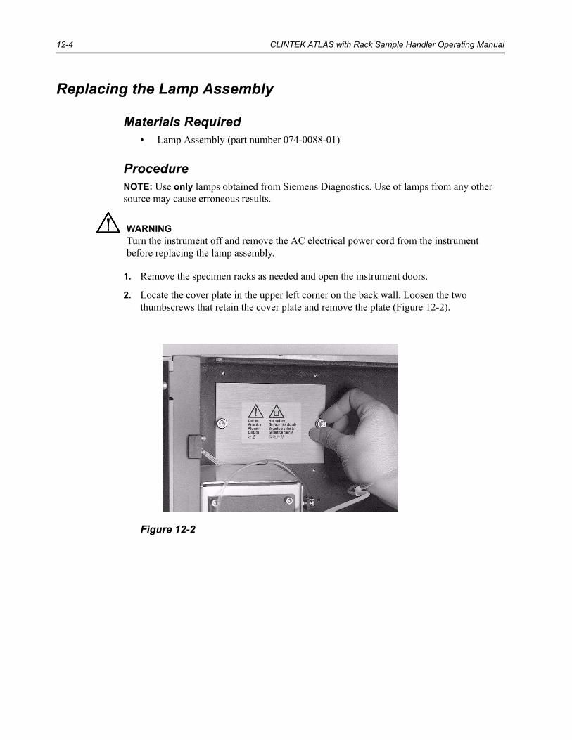
12-4 CLINTEK ATLAS with Rack Sample Handler Operating Manual
Replacing the Lamp Assembly
Materials Required• Lamp Assembly (part number 074-0088-01)
ProcedureNOTE: Use only lamps obtained from Siemens Diagnostics. Use of lamps from any other source may cause erroneous results.
1. Remove the specimen racks as needed and open the instrument doors.
2. Locate the cover plate in the upper left corner on the back wall. Loosen the two thumbscrews that retain the cover plate and remove the plate (Figure 12-2).
Figure 12-2
WARNINGTurn the instrument off and remove the AC electrical power cord from the instrument before replacing the lamp assembly.

MINOR REPLACEMENT AND ADJUSTMENTS 12-5
3. The lamp area is shown in Figure 12-3. Locate the lamp wire connector, the lamp assembly, the lamp holder, and the lamp lever.
Figure 12-3
4. Disconnect the lamp wire connector by pinching the two tabs on the front and back sides of the connector and pulling straight down (Figure 12-4).
Figure 12-4
1 Lamp wire connector2 Lamp Assembly3 Lamp Holder4 Lamp Lever
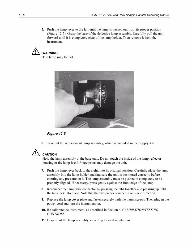
12-6 CLINTEK ATLAS with Rack Sample Handler Operating Manual
5. Push the lamp lever to the left until the lamp is pushed out from its proper position (Figure 12-5). Grasp the base of the defective lamp assembly. Carefully pull the unit forward until it is completely clear of the lamp holder. Then remove it from the instrument.
Figure 12-5
6. Take out the replacement lamp assembly, which is included in the Supply Kit.
7. Push the lamp lever back to the right, into its original position. Carefully place the lamp assembly into the lamp holder, making sure the unit is positioned correctly before exerting any pressure on it. The lamp assembly must be pushed in completely to be properly aligned. If necessary, press gently against the front edge of the lamp.
8. Reconnect the lamp wire connector by pressing the tabs together and pressing up until the tabs lock into place. Note that the two pieces connect in only one direction.
9. Replace the lamp cover plate and fasten securely with the thumbscrews. Then plug in the power cord and turn the instrument on.
10. Re calibrate the instrument, as described in Section 6, CALIBRATION/TESTING CONTROLS.
11. Dispose of the lamp assembly according to local regulations.
WARNINGThe lamp may be hot.
CAUTIONHold the lamp assembly at the base only. Do not touch the inside of the lamp reflector housing or the lamp itself. Fingerprints may damage the unit.

MINOR REPLACEMENT AND ADJUSTMENTS 12-7
Replacing the Pipette Assembly
Materials Required• Pipette Assembly (part number 074-B042-01)
Procedure1. From the Main Menu, press 9.
2. Enter the default password (entry code) of 2633, or your personalized code, to enter the Analyzer Diagnostics menu.
3. Press 1 for Replace Hardware.
4. Press 1 for Replace Pipette.
The display will change to show the first of five screens of instructions. Follow the on-screen directions, referring to this manual for complete information.
5. Remove the specimen racks as needed, then press MOVE PIPETTE. The pipette will be moved forward so that it is accessible.
6. After all movement has ceased, open both the instrument doors.
7. Place a small cup under the pipette tip.
8. To remove the pipette tubing from the syringe valve, loosen the finger nut that connects the tubing to the right side of the valve (Figure 12-6). The liquid will drain into the cup beneath the pipette. Remove the tubing from the clip on the back wall of the instrument.
Figure 12-6

12-8 CLINTEK ATLAS with Rack Sample Handler Operating Manual
9. Locate the wire and small plug that connects the pipette into the back wall of the instrument. Disconnect the plug from its receptacle (Figure 12-7) by pressing down firmly on the tab at the top of the plug and pulling straight out (similar to disconnecting a telephone jack).
Figure 12-7
10. After the tubing is completely free, remove the two thumbscrews on the square block that mounts the pipette to its holder (Figure 12-8). Lift the pipette up and forward from the holder.
Figure 12-8

MINOR REPLACEMENT AND ADJUSTMENTS 12-9
11. Remove the new pipette assembly (included in the Supply Kit) from the plastic container. Remove the large outer shield, then carefully remove the small inner shield, pulling down from the top of the pipette.
12. Hold the new pipette with the flat side of the mounting block facing forward.
Carefully fit the tip down into the slot of the holder bar and fit the mounting block into the holder (Figure 12-9). Be sure the tip does not touch the holder as it is being inserted.
Replace the two thumbscrews and tighten to just past finger tight.
Figure 12-9
13. Holding the small plug with the tab facing up, insert the plug into its receptacle on the back wall of the instrument. Press in firmly until it snaps into place. Then, press the tubing retainer into the clip on the back wall.
14. Insert the end of the tubing into the valve opening and tighten the nut to just past finger tight. Do not overtighten, as this may strip the threads.
15. Close the instrument doors and press the CONTINUE softkey.
16. Press POSITION PIPETTE. The pipette will be moved back to its proper “home” position and the system will be primed.
CAUTIONThe pipette tip is fragile and easily damaged. Do not handle the tip or allow the assembly to drop onto its end.

12-10 CLINTEK ATLAS with Rack Sample Handler Operating Manual
17. After the priming cycle is complete, the pipette will dispense a drop of liquid onto the first pad of the used reagent strip on the platform. Open the instrument doors and confirm that the liquid has been dispensed onto the center of the first pad.
If the drop is dispensed onto the platform or between the pads, check that the pipette has been properly installed. Contact your local technical support provider if the problem cannot be resolved.
18. Close the instrument doors and press DONE. The display will return to the Replace Hardware menu.
19. Discard the old pipette assembly in an appropriate container.
20. Recalibrate the instrument, as described in Section 6, CALIBRATION/TESTING CONTROLS.

MINOR REPLACEMENT AND ADJUSTMENTS 12-11
Replacing the Rinse Tubing
Materials Required• Open End Wrench (5/16 inch)• Hex Key Wrench (3/32 inch)• Rinse Tubing (part number 95001722)
Procedure1. From the Main Menu, press 9.
2. Enter the default password (entry code) of 2633, or your personalized code. The display will change to the Analyzer Diagnostics menu.
3. Press 1 for Replace Hardware.
4. Press 2 for Replace Rinse Tubing. The display will change to show the first of four screens of instructions. Follow the on-screen directions, referring to this manual for complete information.
5. Remove the specimen racks as needed and open the instrument doors.
6. Leave the cannula end of the rinse tubing inserted in the rinse bottle. Using the open end wrench, loosen the fitting that connects the other end of the tubing to the left side of the valve (Figure 12-10).
7. Remove the tubing from the valve. The liquid in the tubing will drain back into the rinse bottle.
Figure 12-10
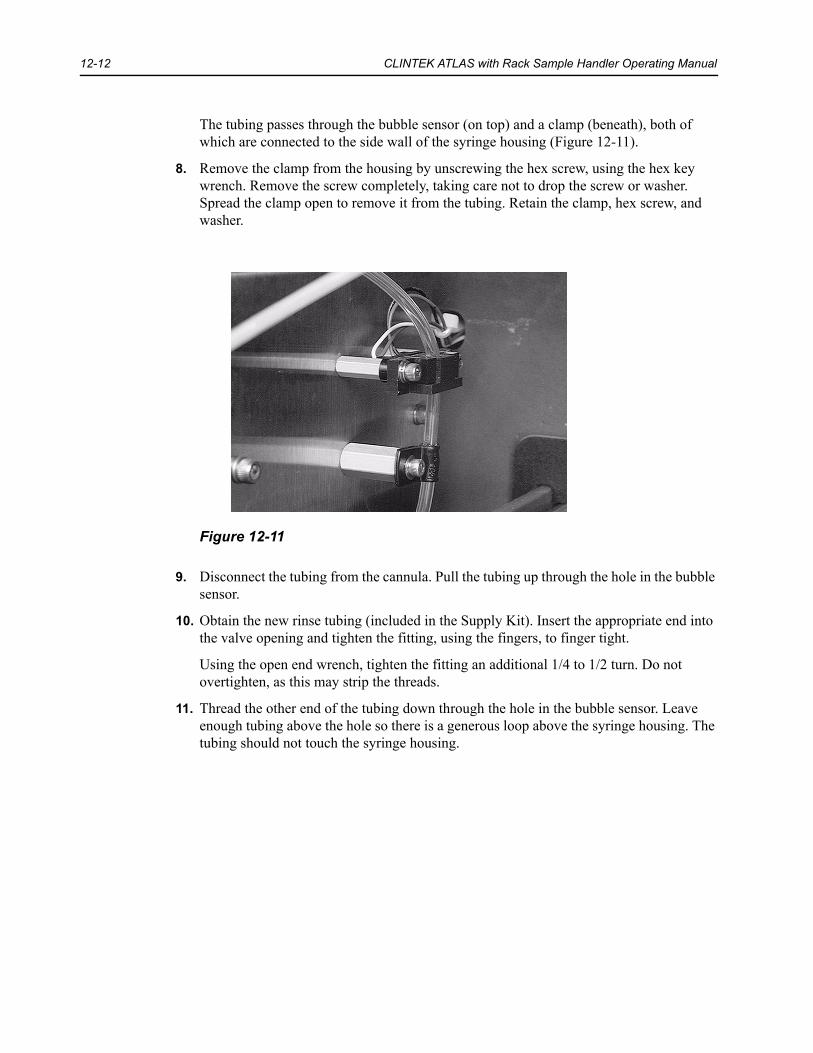
12-12 CLINTEK ATLAS with Rack Sample Handler Operating Manual
The tubing passes through the bubble sensor (on top) and a clamp (beneath), both of which are connected to the side wall of the syringe housing (Figure 12-11).
8. Remove the clamp from the housing by unscrewing the hex screw, using the hex key wrench. Remove the screw completely, taking care not to drop the screw or washer. Spread the clamp open to remove it from the tubing. Retain the clamp, hex screw, and washer.
Figure 12-11
9. Disconnect the tubing from the cannula. Pull the tubing up through the hole in the bubble sensor.
10. Obtain the new rinse tubing (included in the Supply Kit). Insert the appropriate end into the valve opening and tighten the fitting, using the fingers, to finger tight.
Using the open end wrench, tighten the fitting an additional 1/4 to 1/2 turn. Do not overtighten, as this may strip the threads.
11. Thread the other end of the tubing down through the hole in the bubble sensor. Leave enough tubing above the hole so there is a generous loop above the syringe housing. The tubing should not touch the syringe housing.

MINOR REPLACEMENT AND ADJUSTMENTS 12-13
12. Hold the clamp so the longer arm is to the right, with the opening for the tube to the back (see Figure 12-12).
Figure 12-12
13. Thread the tubing through the opening in the clamp (or spread the clamp apart enough to slip the tubing in).
14. Slide the clamp up the tubing until it is in the approximate position under the bubble sensor.
15. Put the washer on the hex screw. Insert the screw through both holes on the arms of the clamp (Figure 12-13).
16. Loosely connect the clamp to the syringe housing. You may find it easier to get started if you place the hex wrench into the hex screw head before beginning. Be sure the opening on the clamp is straight up and down.
Figure 12-13

12-14 CLINTEK ATLAS with Rack Sample Handler Operating Manual
17. Hold onto the clamp so it does not rotate. Then gently pull the tubing so it is straight between the clamp and bubble sensor, while maintaining the generous loop above the syringe housing. Continue holding the clamp in position and securely tighten the hex screw.
18. Thread the tubing through the hole on the side of the instrument and connect it to the cannula.
19. Check that the tubing is completely straight between the bubble sensor and the clamp (the clamp opening must be straight up and down).
20. Press CONTINUE. A series of readings will be taken on the dry tube as it passes through the bubble sensor, then the display will change to a new set of instructions. If necessary, refill the rinse container, insert the cannula into the bottle, and empty the waste container.
21. Ensure that the tubing is securely connected on both ends and that the cannula is inserted into the rinse bottle. Press FILL TUBE and watch the liquid level in the rinse tubing. Continue pressing FILL TUBE until the liquid has been drawn completely through the tubing and into the syringe and no air bubbles are seen in the syringe as it fills. If the rinse tubing is longer than 4 feet, manually prime the extra length of tubing first.
NOTE: If a leak is seen while the liquid is being pulled into the tubing, press LEAKING. Remove the tubing as instructed in Steps 4 to 6 previously. The tubing must be completely dry before reinstalling. Any water droplets in the tube can be blown out using forced air. Then reinstall the tubing as instructed in Steps 7 to 11. Press CONTINUE and repeat Step 13.
22. When the liquid has filled the tubing and syringe, press CONTINUE. A second series of readings will be taken through the bubble sensor and the pump will prime, after which the display will change to the final set of instructions.
23. Close the instrument doors and press DONE when finished. The display returns to the Replace Hardware menu.
24. Discard the old rinse tubing in an appropriate container.
25. Recalibrate the instrument, as described in Section 6, CALIBRATION/TESTING CONTROLS.

MINOR REPLACEMENT AND ADJUSTMENTS 12-15
Replacing the Syringe
Materials Required• Pump Syringe (part number 50559017)
Procedure1. From the Main Menu, press 9, then enter the default password (entry code) of 2633, or
your personalized code, to change the display to the Analyzer Diagnostics menu.
2. Press 1 for Replace Hardware, then 3 for Replace Syringe. The plunger on the syringe will be pulled down approximately half way and the display will change to show the first of three screens of instructions. Follow the on-screen directions, referring to this manual for complete information.
3. Remove the specimen racks as needed and open the instrument doors.
4. Unscrew the syringe from its fitting on the valve by rotating the syringe body clockwise while pulling gently downward (Figure 12-14).
Figure 12-14

12-16 CLINTEK ATLAS with Rack Sample Handler Operating Manual
5. Once the tip of the syringe is completely free from the valve, loosen and remove the screw that secures the plunger onto the syringe mounting plate on the instrument (Figure 12-15). Be sure to continue holding the syringe with one hand while removing the screw with the other. Remove the syringe and set aside.
Figure 12-15
6. Obtain a new syringe (included in the Supply Kit) and remove it carefully from its box. The syringe may be packaged unassembled (body and plunger separate) or assembled (plunger already inserted into the body). Follow the appropriate step for preparing the syringe, as described below:
• If the syringe is unassembled, dip the plunger into the bottle of Rinse Solution to wet the seal end, then slowly push the plunger into the body until it is slightly more than half way inserted (to about the 1000 mL line).
• If the syringe is already assembled, draw up a small quantity of Rinse Solution, then continue pulling against the plunger until it is slightly less than half way withdrawn (approximately the 1000 mL line).
7. Fit the hole on the plunger onto the pin under the syringe mounting plate and loosely replace the plunger screw.

MINOR REPLACEMENT AND ADJUSTMENTS 12-17
8. Gently pull up on the syringe body to extend the length until it fits into the hole at the base of the valve. Rotate the body counterclockwise while continuing to lift gently until the syringe is firmly connected into the valve. The syringe should thread easily all the way to the top. If it doesn’t, loosen it and try again. Tighten the plunger screw to finger tight only. Do not overtighten. Press the CONTINUE softkey when the syringe is properly installed. The display will change to the next set of instructions.
9. Refill the rinse container, if necessary, then press PRIME PUMP. The syringe will go through a priming sequence of several aspirations and dispense cycles. Watch the syringe fitting carefully to ensure there are no leaks. If there is any leakage, reinstall the syringe, carefully ensuring that it is securely screwed into the valve, then press PRIME PUMP again. If there are no leaks, press CONTINUE.
10. Close the instrument doors and press DONE. The display will return to the Replace Hardware menu.
11. Discard the old syringe in an appropriate container.
12. Recalibrate the instrument, as described in Section 6, CALIBRATION/TESTING CONTROLS.
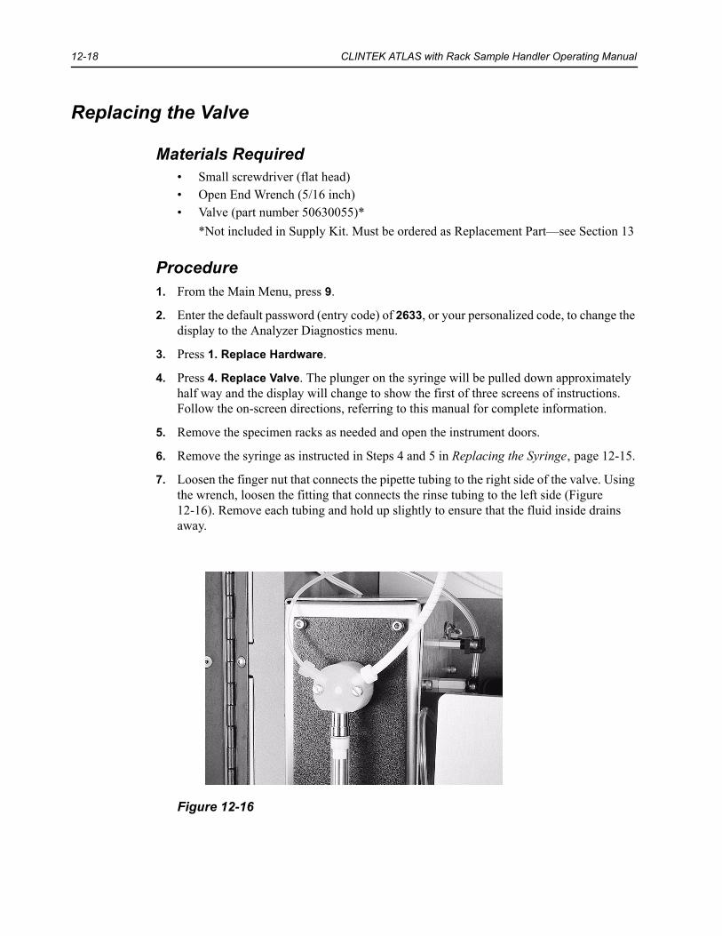
12-18 CLINTEK ATLAS with Rack Sample Handler Operating Manual
Replacing the Valve
Materials Required• Small screwdriver (flat head)• Open End Wrench (5/16 inch)• Valve (part number 50630055)*
*Not included in Supply Kit. Must be ordered as Replacement Part—see Section 13
Procedure1. From the Main Menu, press 9.
2. Enter the default password (entry code) of 2633, or your personalized code, to change the display to the Analyzer Diagnostics menu.
3. Press 1. Replace Hardware.
4. Press 4. Replace Valve. The plunger on the syringe will be pulled down approximately half way and the display will change to show the first of three screens of instructions. Follow the on-screen directions, referring to this manual for complete information.
5. Remove the specimen racks as needed and open the instrument doors.
6. Remove the syringe as instructed in Steps 4 and 5 in Replacing the Syringe‚ page 12-15.
7. Loosen the finger nut that connects the pipette tubing to the right side of the valve. Using the wrench, loosen the fitting that connects the rinse tubing to the left side (Figure 12-16). Remove each tubing and hold up slightly to ensure that the fluid inside drains away.
Figure 12-16

MINOR REPLACEMENT AND ADJUSTMENTS 12-19
8. Loosen the two screws that hold the valve to the syringe plate on the instrument, using a small flathead screwdriver. Remove the valve from the plate.
9. Remove and save the screws from the old valve before discarding it. Obtain a new valve.
10. Locate the small “D” shaped peg on the back side of the valve and align it with the “D” shaped hole in the syringe plate. Insert the peg into the hole, then, if necessary, gently turn the valve counterclockwise until the syringe fitting is pointing down (Figure 12-17). Rotate the valve slightly in each direction until the two small pins on the valve slip into the holes on the mounting plate. When the valve can no longer be rotated (and the syringe fitting is facing down), the valve is properly located.
Figure 12-17
11. Place the screws into the valve and tighten each to just past finger tight.
12. Replace each tubing into its appropriate hole on the valve. The rinse tubing should go in the left side and the pipette tubing in the right side. Tighten each of the fittings, using the fingers, until finger tight. Then turn each fitting an additional 1/4 to 1/2 turn using the wrench for the left side and the fingers for the right side. Do not overtighten, as this may strip the threads.
13. Install the syringe as instructed in Steps 6 to 8 in Replacing the Syringe‚ page 12-15. Press the CONTINUE softkey when the syringe is properly reinstalled.
14. Refill the rinse container, if necessary, then press PRIME PUMP. The syringe will go through a priming sequence of several aspiration and dispense cycles. Watch for the following items:
• As the syringe homes for the first time, make sure the valve does not shift its position. If it does, tighten the screws slightly more.
• Check for leakage at the syringe fitting. If any is observed, reinstall the syringe, carefully ensuring that it is securely screwed into the valve fitting.

12-20 CLINTEK ATLAS with Rack Sample Handler Operating Manual
• Check the tubing fittings carefully to ensure that there are no leaks and that the syringe is filled with fluid only (no air) after the first two cycles. A loose fitting in the tubing from the Rinse Solution (left side) will cause the syringe to draw air.
• Fluid will leak from the fitting for the pipette tubing (right side) if it has not been tightened sufficiently. Carefully tighten the nut on the tubing fitting, as necessary, turning it no more than 1/4 to 1/2 additional turn.
If there is any leakage, tighten the loose fittings and press PRIME PUMP again. Recheck for leakage. When there are no leaks, press CONTINUE.
15. Close the instrument door and press DONE. The display will return to the Replace Hardware menu.
16. Discard the old valve in an appropriate container.
17. Recalibrate the instrument, as described in Section 6, CALIBRATION/TESTING CONTROLS.

MINOR REPLACEMENT AND ADJUSTMENTS 12-21
Lubricating the Syringe Lead Screw
If the syringe mechanism begins making a squeaking or grinding sound, the lead screw should be lubricated.
Materials Required• Lead Screw Lubricant (part number 50336038)
Procedure1. Be sure the instrument is in the Standby Mode (Ready for Testing screen) so the syringe
is in its uppermost position. Turn the instrument off.
2. Obtain the Lead Screw Lubricant, which is included in the Supply Kit. Accompanying the lubricant is an instruction sheet with complete information on its use. Follow these instructions, cleaning the lead screw if necessary, then drawing a thin line of lubricant down the length of the lead screw (Figure 12-18).
NOTE: Use the lubricant very sparingly. It is helpful to gently press out a small amount of lubricant onto a tissue before attempting to apply it to the lead screw.
Figure 12-18
3. Turn the instrument on. After the instrument has completed its initialization cycle, enter the Main Menu and press 5 to prime the pump. This will distribute the lubricant over the full length of the lead screw.

12-22 CLINTEK ATLAS with Rack Sample Handler Operating Manual

13 SERVICE, SUPPLIES AND PARTS
Service Information
When You Have a Problem With the Instrument
When problems arise during operation of the CLINITEK ATLAS Analyzer, first refer to Section 10, TROUBLESHOOTING. Avoid problems by carefully following proper operating and cleaning procedures. If the problem cannot be solved and an instrument failure is apparent, your local technical service provider is available to assist you.
Before calling for instrument service, collect the information stated in the “Preservice Checklist” in this section. This information will help your local technical service provider to identify the probable cause of your instrument malfunction.
Where to Call for Service
Contact your local technical service provider for service information and assistance.

13-2 CLINTEK ATLAS with Rack Sample Handler Operating Manual
Preservice ChecklistYes No
1. Is the “Analyzer Initializing” screen displayed within one minute after the instrument is first turned on?
2. If Step 1 is NO:
• Is the instrument plugged into a live AC electrical outlet?
• Is the line fuse defective? (See Section 12.)
• Do you hear the fan operating?
3. Is the appropriate sequence of screens displayed when the instrument is first turned on?
4. Is the rear panel of the instrument warm (if instrument has been turned on for a period of time)?
5. Is the keyboard operating properly?
6. If Step 5 is NO, have you performed the Keypad Test through the Diagnostics routine? (See Section 11.)
7. Does the lamp illuminate brightly when the instrument is in the Analyze Mode? (If NO, see Section 12 to replace lamp.)
8. Does the instrument proceed properly during the Analyze Mode?
9. Are any error messages or warnings being displayed?
If so, what are they? (List the error description and any numbers that are displayed.) ______________________________________________________________________________________
10. If unable to complete the Calibration sequence or if unusual results are being obtained with controls or routine samples:
• Has the Reagent Pak passed its expiration date?
• Have the Calibration Solutions passed their expiration dates?
• Have the bottles of Control Strips passed their expiration dates or have the Control Solutions passed their use life (8 hours)?
• Has the readhead been cleaned? (See “Periodic Maintenance” in Section 10.)
11. Are reasonable results being displayed for the controls and patient samples?
12. What is the software revision level being used? (Press “4” from the Analyzer Diagnostics menu.) __________
13. Have you performed the appropriate tests through the Analyzer Diagnostics routine for the problem being seen?
14. Is the rinse bottle full?
• Was distilled or deionized water used in preparing the Rinse Solution?
• Was CLINITEK ATLAS Rinse Additive added to the water?
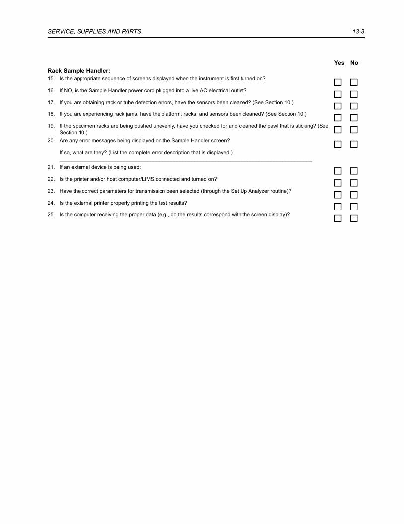
SERVICE, SUPPLIES AND PARTS 13-3
Rack Sample Handler:15. Is the appropriate sequence of screens displayed when the instrument is first turned on?
16. If NO, is the Sample Handler power cord plugged into a live AC electrical outlet?
17. If you are obtaining rack or tube detection errors, have the sensors been cleaned? (See Section 10.)
18. If you are experiencing rack jams, have the platform, racks, and sensors been cleaned? (See Section 10.)
19. If the specimen racks are being pushed unevenly, have you checked for and cleaned the pawl that is sticking? (See Section 10.)
20. Are any error messages being displayed on the Sample Handler screen?
If so, what are they? (List the complete error description that is displayed.) ______________________________________________________________________________________
21. If an external device is being used:
22. Is the printer and/or host computer/LIMS connected and turned on?
23. Have the correct parameters for transmission been selected (through the Set Up Analyzer routine)?
24. Is the external printer properly printing the test results?
25. Is the computer receiving the proper data (e.g., do the results correspond with the screen display)?
Yes No

13-4 CLINTEK ATLAS with Rack Sample Handler Operating Manual
To Order Supplies and Replacement Parts
A complete list of available Supplies and Replacement Parts is provided below. Where appropriate, descriptions of the items available is provided.
In the United States, Replacement Parts may be ordered directly from:
Order ServicesSiemens Diagnostics115 Norwood Park SouthNorwood, MA 02062or by calling toll free:1-800-255-3232
Outside of the United States, contact your local technical service provider.

SERVICE, SUPPLIES AND PARTS 13-5
CLINITEK ATLAS Supply Items
Part Number DescriptionCLINITEK ATLAS Reagent Pak (Product Number 5017)
The CLINITEK ATLAS 10 Reagent Pak contains a roll of reagent strips, each containing reagent areas for testing glucose, bilirubin, ketone (acetoacetic acid), occult blood, pH, protein, urobilinogen, nitrite, and leukocytes. The reagent roll also provides a pad for determining the color of the specimen. When combined with the specific gravity and clarity measurements provided by the instrument’s SG refractometer/clarity device, a full chemistry profile is provided. Each CLINITEK ATLAS Reagent Pak provides at least 490 determinations.
CLINITEK ATLAS Calibration Kit (Product Number 5018A)
The CLINITEK ATLAS Calibration Kit contains four bottles (#1, #2, #3, and #4) of Calibrator Solution. Each bottle contains 230 mL.The instrument must be calibrated using these calibrators each time a new reagent roll is loaded (unless the last calibration was performed within the previous 24 hours and the lot number of the reagent roll has not changed). Certain instrument errors and hardware replacements may also require recalibration. Calibration can also be requested at any time through the Analyze Mode. Refrigeration of Calibrators #1, #2, and #3 is required.
CLINITEK ATLAS Calibrator #4 (Clarity)(Product No. 5006)
CLINITEK ATLAS Calibrator #4 (Clarity) is also available as a separate item.
CLINITEK ATLAS Positive and Negative Control Strips for UrinalysisPositive Control Strips (Product Number 5019)Negative Control Strips(Product Number 5037)
CLINITEK ATLAS Positive and Negative Control Strips for Urinalysis provide positive or negative results for all parameters that are analyzed by the CLINITEK ATLAS Analyzer. The Control Strips provide confidence that the CLINITEK ATLAS Reagent Pak is reacting properly and that the instrument is functioning properly. Each bottle contains 25 strips.
CLINITEK ATLAS Rinse Additive(Product Number 5007A)
The Rinse Additive is added to distilled or deionized water to make the Rinse Solution that is used by the instrument to rinse the pipette tip and SG well. It is provided as four bottles of 26 mL each. Each bottle is sufficient to make 13 liters (2 mL/1000 mL distilled water) of Rinse Solution (the instrument requires 1 liter per reagent roll).

13-6 CLINTEK ATLAS with Rack Sample Handler Operating Manual
CLINITEK ATLAS Rack Sample Handler (Product Number 074-A004-02)
The CLINITEK ATLAS Rack Sample Handler can be attached to the CLINITEK ATLAS Analyzer to provide fast, efficient processing of large numbers of samples.
CLINITEK ATLAS Bar Code Reader(Product Number 5258)
The bar code reader can be mounted onto the Rack Sample Handler to allow specimen identification numbers to be automatically read through the use of bar-coded labels adhered to the tubes. Four different bar code formats can be used: Code 39, Code 128, Codabar, and Interleaved 2 of 5. Labels as small as 10,80 mm (0.39 x 3.15 inches) can be used. Larger sizes, which allow for the printing of human readable information, are acceptable.
CLINITEK ATLAS Specimen Racks(Product Number 5262)
The CLINITEK ATLAS Specimen Racks are the only racks that can be used on the Rack Sample Handler. Ten racks are included with the Sample Handler. Additional racks can be purchased to allow more specimens to be tested in a single run.
CLINITEK ATLAS STAT Rack(Product Number 5263)
This special rack holds up to 10 tubes for use in STAT testing. When the rack is detected, the prefix on the sequential number assigned to each tube changes to “S.” Bar-coded labels on the STAT tubes can be read using the Bar code Reader (Product No. 5258).The STAT Rack looks nearly identical to the routine specimen racks (Product Number 5262). The only difference is a small opening on the bottom of the open side of the rack. Therefore, it is strongly suggested that you label the STAT rack in some manner as soon as you receive it, so it is not inadvertently used for routine testing.
Part Number Description
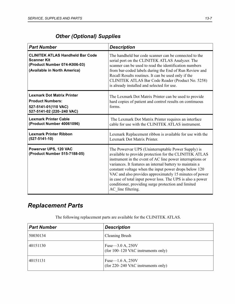
SERVICE, SUPPLIES AND PARTS 13-7
Other (Optional) Supplies
Replacement Parts
The following replacement parts are available for the CLINITEK ATLAS.
Part Number DescriptionCLINITEK ATLAS Handheld Bar Code Scanner Kit(Product Number 074-K006-03)(Available in North America)
The handheld bar code scanner can be connected to the serial port on the CLINITEK ATLAS Analyzer. The scanner can be used to read the identification numbers from bar-coded labels during the End of Run Review and Recall Results routines. It can be used only if the CLINITEK ATLAS Bar Code Reader (Product No. 5258) is already installed and selected for use.
Lexmark Dot Matrix PrinterProduct Numbers: 527-5141-01(110 VAC)527-5141-02 (220–240 VAC)
The Lexmark Dot Matrix Printer can be used to provide hard copies of patient and control results on continuous forms.
Lexmark Printer Cable(Product Number 40061096)
The Lexmark Dot Matrix Printer requires an interface cable for use with the CLINITEK ATLAS instrument.
Lexmark Printer Ribbon(527-5141-10)
Lexmark Replacement ribbon is available for use with the Lexmark Dot Matrix Printer.
Powervar UPS, 120 VAC(Product Number 515-7188-05)
The Powervar UPS (Uninterruptable Power Supply) is available to provide protection for the CLINITEK ATLAS instrument in the event of AC line power interruptions or variances. It features an internal battery to maintain a constant voltage when the input power drops below 120 VAC and also provides approximately 15 minutes of power in case of total input power loss. The UPS is also a power conditioner, providing surge protection and limited AC_line filtering.
Part Number Description
50030134 Cleaning Brush
40151130 Fuse—3.0 A, 250V (for 100–120 VAC instruments only)
40151131 Fuse—1.6 A, 250V (for 220–240 VAC instruments only)

13-8 CLINTEK ATLAS with Rack Sample Handler Operating Manual
NOTE: All part numbers are subject to change without notice.
95001723 External Rinse Tubing
95002318 External Waste Tubing
50660047 Hex Key—0.50 inch
50300008 Hex Key—5/32 inch
50302506 Hex Key—7/64 inch
50300022 Hex Key—3/32 inch
50660130 Hex Wrench, Open End —5/16 inch
074-0088-01 Lamp Assembly
71520103 Loopback Connector
50336038 Lubricant
074-B042-01 Pipette Assembly
50559017 Pump Syringe
50048117 Rinse Bottle
95001722 Rinse Tubing
50567525 Stationary Rod Sleeve
50361095 Stop Marker
50630055 Valve
50048118 Waste Bottle
Part Number Description

SERVICE, SUPPLIES AND PARTS 13-9
Instrument Information
Please record the following information. Keep this sheet in the operating manual for future reference
Date of Installation
Analyzer Model/Serial Number
Rack Sample Handler Model/Serial Number

13-10 CLINTEK ATLAS with Rack Sample Handler Operating Manual

14 BAR CODE Reader
General Information
The CLINITEK ATLAS bar code reader is available for the CLINITEK ATLAS Automated Urine Chemistry Analyzer when used with the CLINITEK ATLAS Rack Sample Handler. When installed and selected as the source of specimen identification numbers, the bar code reader will scan bar coded labels that are adhered to the specimen tubes, providing a positive identification for each tube. (The information provided in this section does not apply to the optional handheld bar code scanner, although some of the bar code format details may be the same.)
Four different bar code formats can be used:
• Code 39 • Code 128• Codabar (NW-7)• Interleaved 2 of 5
The software in the CLINITEK ATLAS Rack Sample Handler can be programmed to accept only one format, or to discriminate automatically between the different formats.
Installation
The bar code reader will be installed by your local technical support provider.
Setting Up and Testing the Bar Code Reader
After the bar code reader has been installed and all installation procedures have been completed on the CLINITEK ATLAS instrument, the bar code reader must be selected as ON through the User Setup Mode on the Rack Sample Handler. The Sample Handler must also be selected as the Specimen ID Source through the Set Up Analyzer menu. Refer to User Setup Mode—Sample Handler‚ page 4-1 and Specimen Information Menu‚ page 4-15 for complete information on selecting the ID Source and setting up the bar code reader.
To select the appropriate bar code format, follow the instructions given in Section 4 and on the Rack Sample Handler display screen. Ensure that the bar coded labels to be used in your laboratory comply with the specifications given later in this section.

14-2 CLINTEK ATLAS with Rack Sample Handler Operating Manual
Troubleshooting
If the bar coded labels are not positioned properly on the specimen tube, or if the tubes are not positioned properly in the specimen rack, reading problems may occur. Rotate the tube slightly to ensure that the bar codes are showing completely through the open side of the rack and attempt to read the label again. This is especially important if the bar codes are not quite perpendicular to the length of the tube.
It is also important that the labels be printed to the required specifications. Reading errors may occur if:
• the narrow bar width is too small, • the bar code length too great, • the height too small, • or the background reflection too high or low.
The test labels included with the bar code reader can be used to verify the operation of the reader. Two sheets of labels are provided. Each sheet contains two consecutively numbered labels in each of the six format/check digit combinations. These test labels are of a known quality, printed to the minimum narrow bar width the bar code reader should be able to read.
If the reader is not able to consistently read your labels, apply a test label of the format being used to a new specimen tube and perform the Bar Code Test. If the reader is able to read the test label, the quality of your labels may be suspect. If the test label cannot be read, the reader itself is suspect.
If you have problems that cannot be resolved, contact your local technical service provider for assistance.

BAR CODE Reader 14-3
Specifications
Bar Code Formats
The CLINITEK ATLAS bar code reader meets the requirements of ASTM E1466-92, “Standard Specification for Use of Bar Codes on Specimen Tubes in the Clinical Laboratory” (available from ASTM, 100 Barr Harbor Dr., West Conshohocken, PA 19428). In addition to supporting the two formats required by the specification (Code 39 and Code 128), the bar code reader and CLINITEK ATLAS system also support the use of Codabar and Interleaved 2 of 5 (I-2of5). The following information is provided for each format. Additional information can be found in Section 4, CUSTOMIZING THE SOFTWARE.
NOTE: Although some formats support the use of a check digit, the check digit is not verified by the bar code reader or the instrument. If bar code labels with a check digit are used in your laboratory, consider removing this digit. See Remove Trail BC Char‚ page 4-18.
Code 39: This format is also known as Code 3 of 9. The entire 43 character set (alphanumeric and special characters) may be used for the specimen ID number. The asterisk characters appended to both ends of the patient ID for Code 39 during the label creation process are automatically removed by the bar code reader and the handheld bar code scanner. If bar code labels with a check digit are used in your laboratory, consider removing this digit. See Remove Trail BC Char‚ page 4-18.
NOTE: Both upper- and lower-case alphabetic letters can be read. However, only upper-case letters can be entered through the instrument softkeys. Therefore, the use of upper-case letters only is recommended in case a bar coded label is unable to be read and the specimen ID must be entered manually.
Code 128: As with Code 39, the entire 43 character set (alphanumeric and special characters) may be used for the specimen ID number. Refer to the NOTE under Code 39 for information on the use of upper and lower case alphabetic characters.
Codabar (NW-7): Any of the numeric digits (0-9) and six special characters may be used for the specimen ID number. In addition Codabar adds a letter before and after the user ID. This letter is typically an uppercase or lowercase A. The bar code reader and handheld bar code scanner remove these characters.
Interleaved 2 of 5: The specimen ID number must contain numeric digits (0 to 9) only. Interleaved 2 of 5 forces an even number of digits for the specimen ID number. If an odd number of digits has been created, Interleaved 2 of 5 prepends a padding zero in front of the ID. If an odd number of digits is always used for patient IDs, and the padding zero is not wanted, see Section 4, Remove Lead BC Char. for information on removing this character.

14-4 CLINTEK ATLAS with Rack Sample Handler Operating Manual
Bar Code Symbols and Labels
The bar code symbols, and the labels themselves, must meet certain specifications, detailed below:
Number of Characters: 1 to 32 data characters. A maximum of 13 characters can be displayed, stored and transmitted by the CLINITEK ATLAS Analyzer. Excess characters must be removed as leading and/or trailing characters. (see Bar Code Reader‚ page 4-3)
Narrow Bar Width: 0.19 to 0.51 mm (0.0075 to 0.02 inch). It is better to be closer to the upper limit (0.51 mm/0.02 inch), as long as the entire bar code can be contained within the maximum length.
Narrow to Wide Ratio: Must be within the specifications for the format being used. This is generally 2.0 to 3.0.
Symbol Length: Maximum of 80 mm (3.15 inches), including the quiet zones.
Quiet Zone: Minimum of ten times the narrow bar width at each end of the symbol.
Symbol Height: Minimum of 10 mm (0.40 inch). Larger than 10 mm is better, as it permits more error in positioning the sample tubes in the tray.
Total Size of Label: May be greater than 10 mm by 80 mm (0.39 inch by 3.15 inches) to allow for printing of human readable information. Printing of the specimen ID number in alphanumeric digits is strongly recommended.
Placement of Label: Must be placed on sample tube so the entire bar code symbol, including the quiet zones, is visible through the open side of the specimen rack.
Orientation of Label: Must be placed so the bars are perpendicular to the length of the specimen tube. The skew from perpendicular should be less than 5°.
Symbol grade: Minimum grade of “C” as defined by ANSI X3.182-1990 (available from American National Standards Institute, 1430 Broadway, New York, NY 10018).

BAR CODE Reader 14-5
Routine Care
The bar code reader and handheld bar code scanner require very little in the way of routine care. However, the optic window may become splattered with urine. Therefore, once each month, or whenever residue is noticed, the window should be cleaned. Wipe with a damp, soft cloth until all residue is gone, then dry with a soft cloth.
Several solutions are acceptable for disinfecting the bar code reader and handheld bar code scanner. Cidex and Theracide are commercially available products that can safely be used. 70–85% isopropanol is also acceptable. Wet the optic window and case with solution. Wait the appropriate length of time for the solution used, then wipe off with water and dry.

14-6 CLINTEK ATLAS with Rack Sample Handler Operating Manual

Appendix A: List of Symbols
Symbol Description
Used for both Warning and Caution.A warning indicates the risk of personal injury or loss of life. A caution indicates the possibility of loss of data or damage to or destruction of equipment.
Warning. Biohazard
Warning. Hot surface
Lift here. Left.
Lift here. Right.
Lock-Unlock
Rinse solution dilution.

A-2 CLINTEK ATLAS with Rack Sample Handler Operating Manual
Symbol Description
BACKUP
STANDBY
ENTER
ON/OFF
Printer (IEC 5193)
Revision Number
Fuse
In Vitro Diagnostic Medical Device
The product meets the safety requirements of Underwriters Laboratories (United States).
The product meets the safety requirements of Underwriters Laboratories and Canadian Standards Association. (Canada).
Manufactured by

A-3
Symbol Description
Authorized Representative
CE Mark. Product meets the requirements of applicable European Directives.
Serial Number
Catalog Number
Manufacturing Date
Class 1 Laser Classification Label. This label is added to the system only if the optional handheld bar code scanner is used.

A-4 CLINTEK ATLAS with Rack Sample Handler Operating Manual

Appendix B: List of Offices
For Service
To contact the legal representative for Siemens Diagnostics within the European community, contact the Siemens Diagnostics Authorized Representative. For service, contact your local technical support provider.
Siemens Diagnostics Authorized Representative
Siemens Medical Solutions Diagnostics Europe LimitedChapel Lane, Swords, Co. Dublin, Ireland
Siemens Diagnostics Offices Worldwide
Siemens Medical SolutionsDiagnostics Pty LtdABN 65 007 436 651885 Mountain HighwayBayswater Victoria 3153Australia

B-2 CLINTEK ATLAS with Rack Sample Handler Operating Manual

Appendix C: Protecting Yourself from Biohazards
This information summarizes the established guidelines for handling laboratory biohazards. This summary is based on the guidelines developed by the National Institutes of Health (NIH), the Centers for Disease Control (CDC), the NCCLS Document M29-A, Protection of Laboratory Workers from Instrument Biohazards and Infectious Disease Transmitted by Blood, Body Fluids, and Tissue, and the Occupational Safety and Health Administration’s Bloodborne Pathogens Standard.1–3
Use this summary for general information only. It is not intended to replace or supplement your laboratory or hospital biohazard control procedures.
By definition, a biohazardous condition is a situation involving infectious agents biological in nature, such as the hepatitis B virus, the human immunodeficiency virus (HIV), and the tuberculosis bacterium. These infectious agents may be present in human blood and blood products and in other body fluids.
The following are the major sources of contamination when handling potentially infectious agents:
• needlesticks• sharp objects, such as probe tips• hand-to-mouth contact • hand-to-eye contact • direct contact with superficial cuts, open wounds, and other skin conditions that may
permit absorption into subcutaneous skin layers • splashes or aerosol contact with skin and eyes

C-2 CLINTEK ATLAS with Rack Sample Handler Operating Manual
To prevent accidental contamination in a clinical laboratory, strictly adhere to the following procedures:
• Wear gloves while handling parts of the instrument that have contact with body fluids such as serum, plasma, urine, or whole blood.
• Wash your hands before going from a contaminated area to a non-contaminated area, or when you remove or change gloves.
• Perform procedures carefully to minimize aerosol formation.• Wear facial protection when splatter or aerosol formation are possible. • Wear personal protective equipment such as safety glasses, gloves, lab coats or other
protective clothing when working with possible biohazard contaminants. • Keep your hands away from your face. • Cover superficial cuts and wounds. • Dispose of contaminated materials according to your laboratory’s biohazard control
procedures.• Disinfect your work area with a 15% bleach solution.• Do not eat, drink, smoke, or apply cosmetics or contact lenses while in the
laboratory. • Do not pipette any liquid, including water, with your mouth.• Do not place any tools or any other items in your mouth.• Do not use the biohazard sink for any personal cleaning, such as rinsing cups or
washing hands.
To prevent needlestick injuries, needles should not be recapped, purposely bent, cut, broken, removed from disposable syringes, or otherwise manipulated by hand.
References1. Centers for Disease Control. 1988. Update: Universal precautions for prevention of
transmission of human immunodeficiency virus, hepatitis B virus and other bloodborne pathogens in healthcare settings. MMWR, 37:377–382, 387, 388.
2. National Committee for Clinical Laboratory Standards. Protection of laboratory workers from instrument biohazards and infectious disease transmitted by blood, body fluids, and tissue; approved guideline. NCCLS Document M29-A. Villanova (PA): NCCLS; 1997 Dec. 90p.
3. Federal Occupational Safety and Health Administration. Bloodborne Pathogens Standard. 29 CFR 1910. 1030.

Appendix D: Laser Safety
If the CLINITEK ATLAS system is equipped with the bar code reader option, it functions during operation as a CDRH Class I (IEC Class 1) Laser Product pursuant to both EN 60825-1 and the United States Code for Federal Regulations, Title 21, Sub-chapter J, Part 1040. The information in this section applies only if the system is equipped with one of the optional bar code reader options.
The rack handler is equipped with a CDRH Class I (IEC Class 1) optical reader with the following characteristics
If the CLINITEK ATLAS is equipped with the optional handheld bar code scanner, the following label will be installed by the service technician:
Maximum power output 25.5 µW
Wavelength 655 nm
Pulse duration 200 ns
Beam divergence N/A

D-2 CLINTEK ATLAS with Rack Sample Handler Operating Manual
This label is positioned as follows:
No operator access to other interior areas of the product is intended for this equipment. Access behind guards or panels that are not interlocked is for service functions only.
Only trained field service personnel should perform procedures related to CLINITEK ATLAS laser assemblies. All field service procedures must be followed precisely.
1 Class 1 Laser Rating Label2 Rating Label

Appendix E: Readhead Optic Placement
During various troubleshooting procedures, you technical service provider may ask you to move some of the optics in the readhead. The diagram below may be useful during that process. It provides details about where the optics are located in the readhead.
Figure E-1
CAUTIONDo not remove or rearrange any optics unless specifically instructed to do so by an authorized technical service provider. Proper placement of the optics is essential to instrument function. In addition, the optics can be damaged by rough handling.
1 Read Optic, Row 12 Source Light Optic, Row 23 Read Optic, Row 34 Source Light Optic, Row 4
5
3
2
1
9
8
7
6
4
13
10
11
12
14
1 42 3

E-2 CLINTEK ATLAS with Rack Sample Handler Operating Manual

Appendix F: Customer Bulletins
Place all customer bulletins in this appendix.

F-2 CLINTEK ATLAS with Rack Sample Handler Operating Manual

Index
AAuthorized Service Representative B-1
BBar Code Formats 14-1Bar Code Reader 14-1
description 1-13laser safety information D-1
Bar Code Scanner 14-1description 1-13laser safety information D-1
Bar Code Scanner, Handheldsetup 4-17
Barcode Reader Formats 4-3Bleach
suggested strength 3-5, 5-1, 6-1, 9-2
CCalibration
minimum quantity of solution 6-2when to calibrate 6-1
Calibration frequency 6-1Clarity
how clarity is determined 1-1Control Solutions
stability 6-5Controls
Postion 6-5Results out of range 6-8Stability 6-5Testing 6-5
DDaily Maintenance 9-2Disinfection 9-13Disposal of waste and supplies 7-20
EEnvironmental Factors
Humidity 2-1Temperatures 2-1
IInstallation 2-1
MMaintenance
Daily 9-2General 9-1Periodic 9-3
Minimum Sample Size 1-3
OOperating Conditions, Ideal and Required 2-1Operation
routine run 7-5
RRack Sample Handler Setup 4-1Readhead, Cleaning 9-4Reagent
components 1-1number of specimens tested per roll 1-3

Index-2
Results Formats 4-48– 4-57
SSample Handler Setup 4-1Service Representative B-1Setup Optional Handheld Bar Code Scanner 4-17Setup Rack Sample Handler 4-1Siemens Diagnostics offices
authorized representatives B-1Specific Gravity 1-1Standby
automatic after end of run 7-10manually placing in 1-5
TTurn Instrument Off
if off for more than one hour 2-2, 3-4, 6-1, 9-1, 9-9
if off for several days 9-1instrument must be left on at all times 1-2,
1-10, 9-1