bayer pattern based cfa zooming / cfa interpolation framework … · bayer pattern based cfa...
TRANSCRIPT
BAYER PATTERN BASED CFA ZOOMING / CFA INTERPOLATION FRAMEWORK
R. Lukac1 K. Martin1 K.N. Plataniotis1 B. Smolka2+ A.N. Venetsanopoulos1
1 The Edward S. Rogers Sr. Department of ECE, University of Toronto, 10 King’s College Road,Toronto, Ontario M5S 3G4, Canada, e-mails: {lukacr, kmartin, kostas, anv}@dsp.utoronto.ca
2 Department of Automatic Control, Silesian University of Technology,Akademicka 16 Str., 44-101 Gliwice, Poland, e-mail: [email protected]
ABSTRACT
A unified framework for Bayer pattern based single-sensorimaging devices is introduced. Operating on the Bayercolor filter array (CFA) data, the method performs CFA im-age zooming and full color image reconstruction in a cost-effective way making the system practical for hardware im-plementation. The high-level system components, namelyCFA zooming, CFA interpolation and CFA based correctionstep utilize a color-ratio model and an edge-sensing mecha-nism to produce naturally colored and sharp, enlarged out-put. Simulation studies presented here indicate that the newmethod produces excellent results and outperforms other ap-proaches in terms of both objective and subjective evaluationmeasures.
1. INTRODUCTION
Single-sensor digital imaging devices typically use a chargecoupled device (CCD) or a complementary metal-oxidesemiconductor (CMOS), combined with a color filter array(CFA) to separate incoming light into a specific spatial ar-rangement of color components. The Bayer pattern (Figure1a) [2] is the most common CFA, providing a mosaic of Red(R), Green (G), and Blue (B) color components.
Technological advances have allowed for the miniatur-ization of single-sensor cameras resulting in their being em-bedded in a myriad of consumer electronic devices. Many ofthese devices, such as mobile phones and personal digital as-sistants (PDAs), are restricted in their optical capabilities andcomputational resources and thus provide limited function-ality and quality of output. To provide high-quality enlargedcamera output in such an imaging device, a unified CFA im-age processing framework is introduced here. The frame-work unifies three algorithmic steps (CFA zooming, CFA in-terpolation and CFA based correction step) designed for cost-effective hardware implementations in single-sensor cam-eras. The employed edge-sensing mechanism tracks varyingimage statistics while a color-ratio model is used in each ofthe algorithmic steps to avoid color artifacts in the output.Therefore, the unified framework produces the enlarged, fullcolor camera output as a sharp, visually pleasing color im-age.
2. PROPOSED SOLUTION
Let us consider a K1 ×K2 Bayer CFA image b : Z2 → Z3
representing a two-dimensional matrix of three-componentRGB vectors b(m,n) = [b(m,n)1,b(m,n)2,b(m,n)3] located in thespatial position (m,n), for m = 1,2, ...,K1 and n = 1,2, ...,K2.
+ Supported by the KBN grant 4T11F01824.
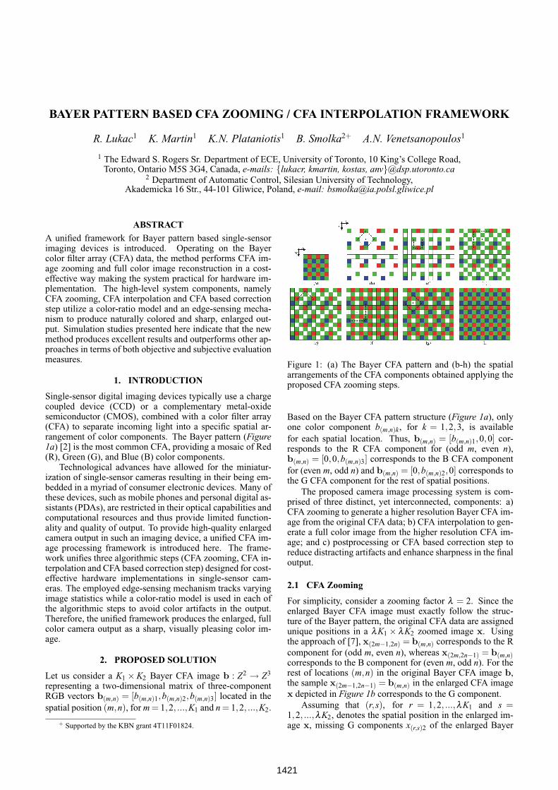
Figure 1: (a) The Bayer CFA pattern and (b-h) the spatialarrangements of the CFA components obtained applying theproposed CFA zooming steps.
Based on the Bayer CFA pattern structure (Figure 1a), onlyone color component b(m,n)k, for k = 1,2,3, is availablefor each spatial location. Thus, b(m,n) = [b(m,n)1,0,0] cor-responds to the R CFA component for (odd m, even n),b(m,n) = [0,0,b(m,n)3] corresponds to the B CFA componentfor (even m, odd n) and b(m,n) = [0,b(m,n)2,0] corresponds tothe G CFA component for the rest of spatial positions.
The proposed camera image processing system is com-prised of three distinct, yet interconnected, components: a)CFA zooming to generate a higher resolution Bayer CFA im-age from the original CFA data; b) CFA interpolation to gen-erate a full color image from the higher resolution CFA im-age; and c) postprocessing or CFA based correction step toreduce distracting artifacts and enhance sharpness in the finaloutput.
2.1 CFA Zooming
For simplicity, consider a zooming factor λ = 2. Since theenlarged Bayer CFA image must exactly follow the struc-ture of the Bayer pattern, the original CFA data are assignedunique positions in a λK1 × λK2 zoomed image x. Usingthe approach of [7], x(2m−1,2n) = b(m,n) corresponds to the Rcomponent for (odd m, even n), whereas x(2m,2n−1) = b(m,n)corresponds to the B component for (even m, odd n). For therest of locations (m,n) in the original Bayer CFA image b,the sample x(2m−1,2n−1) = b(m,n) in the enlarged CFA imagex depicted in Figure 1b corresponds to the G component.
Assuming that (r,s), for r = 1,2, ...,λK1 and s =1,2, ...,λK2, denotes the spatial position in the enlarged im-age x, missing G components x(r,s)2 of the enlarged Bayer
1421
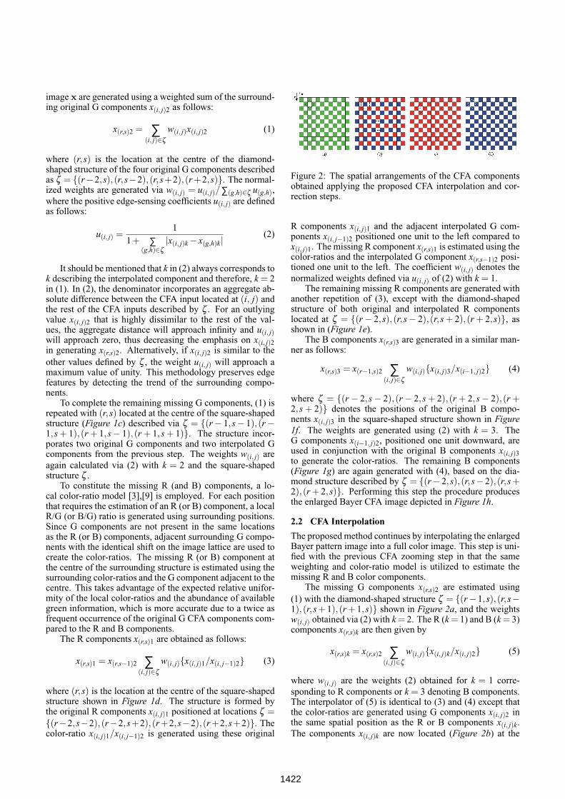
image x are generated using a weighted sum of the surround-ing original G components x(i, j)2 as follows:
x(r,s)2 = ∑(i, j)∈ζ
w(i, j)x(i, j)2 (1)
where (r,s) is the location at the centre of the diamond-shaped structure of the four original G components describedas ζ = {(r−2,s),(r,s−2),(r,s+2),(r+2,s)}. The normal-ized weights are generated via w(i, j) = u(i, j)/∑(g,h)∈ζ u(g,h),where the positive edge-sensing coefficients u(i, j) are definedas follows:
u(i, j) =1
1+ ∑(g,h)∈ζ
|x(i, j)k− x(g,h)k|(2)
It should be mentioned that k in (2) always corresponds tok describing the interpolated component and therefore, k = 2in (1). In (2), the denominator incorporates an aggregate ab-solute difference between the CFA input located at (i, j) andthe rest of the CFA inputs described by ζ . For an outlyingvalue x(i, j)2 that is highly dissimilar to the rest of the val-ues, the aggregate distance will approach infinity and u(i, j)will approach zero, thus decreasing the emphasis on x(i, j)2in generating x(r,s)2. Alternatively, if x(i, j)2 is similar to theother values defined by ζ , the weight u(i, j) will approach amaximum value of unity. This methodology preserves edgefeatures by detecting the trend of the surrounding compo-nents.
To complete the remaining missing G components, (1) isrepeated with (r,s) located at the centre of the square-shapedstructure (Figure 1c) described via ζ = {(r− 1,s− 1),(r−1,s + 1),(r + 1,s− 1),(r + 1,s + 1)}. The structure incor-porates two original G components and two interpolated Gcomponents from the previous step. The weights w(i, j) areagain calculated via (2) with k = 2 and the square-shapedstructure ζ .
To constitute the missing R (and B) components, a lo-cal color-ratio model [3],[9] is employed. For each positionthat requires the estimation of an R (or B) component, a localR/G (or B/G) ratio is generated using surrounding positions.Since G components are not present in the same locationsas the R (or B) components, adjacent surrounding G compo-nents with the identical shift on the image lattice are used tocreate the color-ratios. The missing R (or B) component atthe centre of the surrounding structure is estimated using thesurrounding color-ratios and the G component adjacent to thecentre. This takes advantage of the expected relative unifor-mity of the local color-ratios and the abundance of availablegreen information, which is more accurate due to a twice asfrequent occurrence of the original G CFA components com-pared to the R and B components.
The R components x(r,s)1 are obtained as follows:
x(r,s)1 = x(r,s−1)2 ∑(i, j)∈ζ
w(i, j){x(i, j)1/x(i, j−1)2} (3)
where (r,s) is the location at the centre of the square-shapedstructure shown in Figure 1d. The structure is formed bythe original R components x(i, j)1 positioned at locations ζ ={(r−2,s−2),(r−2,s+2),(r+2,s−2),(r+2,s+2)}. Thecolor-ratio x(i, j)1/x(i, j−1)2 is generated using these original
Figure 2: The spatial arrangements of the CFA componentsobtained applying the proposed CFA interpolation and cor-rection steps.
R components x(i, j)1 and the adjacent interpolated G com-ponents x(i, j−1)2 positioned one unit to the left compared tox(i, j)1. The missing R component x(r,s)1 is estimated using thecolor-ratios and the interpolated G component x(r,s−1)2 posi-tioned one unit to the left. The coefficient w(i, j) denotes thenormalized weights defined via u(i, j) of (2) with k = 1.
The remaining missing R components are generated withanother repetition of (3), except with the diamond-shapedstructure of both original and interpolated R componentslocated at ζ = {(r− 2,s),(r,s− 2),(r,s + 2),(r + 2,s)}, asshown in (Figure 1e).
The B components x(r,s)3 are generated in a similar man-ner as follows:
x(r,s)3 = x(r−1,s)2 ∑(i, j)∈ζ
w(i, j){x(i, j)3/x(i−1, j)2} (4)
where ζ = {(r− 2,s− 2),(r− 2,s + 2),(r + 2,s− 2),(r +2,s + 2)} denotes the positions of the original B compo-nents x(i, j)3 in the square-shaped structure shown in Figure1f. The weights are generated using (2) with k = 3. TheG components x(i−1, j)2, positioned one unit downward, areused in conjunction with the original B components x(i, j)3to generate the color-ratios. The remaining B components(Figure 1g) are again generated with (4), based on the dia-mond structure described by ζ = {(r−2,s),(r,s−2),(r,s +2),(r + 2,s)}. Performing this step the procedure producesthe enlarged Bayer CFA image depicted in Figure 1h.
2.2 CFA Interpolation
The proposed method continues by interpolating the enlargedBayer pattern image into a full color image. This step is uni-fied with the previous CFA zooming step in that the sameweighting and color-ratio model is utilized to estimate themissing R and B color components.
The missing G components x(r,s)2 are estimated using(1) with the diamond-shaped structure ζ = {(r−1,s),(r,s−1),(r,s + 1),(r + 1,s)} shown in Figure 2a, and the weightsw(i, j) obtained via (2) with k = 2. The R (k = 1) and B (k = 3)components x(r,s)k are then given by
x(r,s)k = x(r,s)2 ∑(i, j)∈ζ
w(i, j){x(i, j)k/x(i, j)2} (5)
where w(i, j) are the weights (2) obtained for k = 1 corre-sponding to R components or k = 3 denoting B components.The interpolator of (5) is identical to (3) and (4) except thatthe color-ratios are generated using G components x(i, j)2 inthe same spatial position as the R or B components x(i, j)k.The components x(i, j)k are now located (Figure 2b) at the
1422
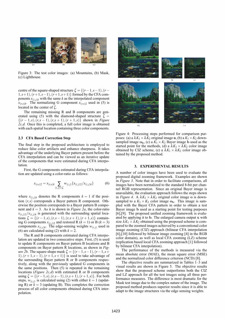
Figure 3: The test color images: (a) Mountains, (b) Mask,(c) Lighthouse.
centre of the square-shaped structure ζ = {(r−1,s−1),(r−1,s+1),(r+1,s−1),(r+1,s+1)} formed by the CFA com-ponents x(i, j)k with the same k as the interpolated componentx(r,s)k. The normalizing G component x(r,s)2 used in (5) islocated in the center of ζ .
The remaining missing R and B components are gen-erated using (5) with the diamond-shaped structure ζ ={(r − 1,s),(r,s − 1),(r,s + 1),(r + 1,s)} shown in Figure2c,d. Once this is completed, a full color image is obtainedwith each spatial location containing three color components.
2.3 CFA Based Correction Step
The final step in the proposed architecture is employed toreduce false color artifacts and enhance sharpness. It takesadvantage of the underlying Bayer pattern present before theCFA interpolation and can be viewed as an iterative updateof the components that were estimated during CFA interpo-lation.
First, the G components estimated during CFA interpola-tion are updated using a color-ratio as follows:
x(r,s)2 = x(r,s)k ∑(i, j)∈ζ
w(i, j){x(i, j)2/x(i, j)k} (6)
where x(i, j)k denotes the R components k = 1 if the posi-tion (r,s) corresponds a Bayer pattern R component. Oth-erwise the position corresponds to a Bayer pattern B compo-nent and k = 3. As it is shown in Figure 2a, the color-ratiox(i, j)2/x(i, j)k is generated with the surrounding spatial loca-tions ζ = {(r− 1,s),(r,s− 1),(r,s + 1),(r + 1,s)} contain-ing G components x(i, j)2 and restored R (k = 1) or B (k = 3)components x(i, j)k. The edge-sensing weights w(i, j) used in(6) are calculated using (2) with k = 2.
The R and B components estimated during CFA interpo-lation are updated in two consecutive steps. First, (5) is usedto update R components on Bayer pattern B locations and Bcomponents on Bayer pattern R locations, as shown in Fig-ure 2b. The square-shape mask ζ = {(r−1,s−1),(r−1,s+1),(r + 1,s− 1),(r + 1,s + 1)} is used to take advantage ofthe surrounding Bayer pattern R or B components respec-tively, along with the previously updated G components inthe same positions. Then (5) is repeated in the remaininglocations (Figure 2c,d) with estimated R or B componentsusing ζ = {(r−1,s),(r,s−1),(r,s+1),(r +1,s)}. For bothsteps, w(i, j) is calculated using (2) with either k = 1 (updat-ing R) or k = 3 (updating B). This completes the correctionprocess of all color components obtained during CFA inter-polation.
Figure 4: Processing steps performed for comparison pur-poses: (a) a λK1×λK2 original image o, (b) a K1×K2 down-sampled image ob, (c) a K1×K2 Bayer image b used as thestarted point for the methods, (d) a λK1 ×λK2 color imageobtained by CIZ scheme, (e) a λK1 ×λK2 color image ob-tained by the proposed method.
3. EXPERIMENTAL RESULTS
A number of color images have been used to evaluate theproposed digital zooming framework. Examples are shownin Figure 3. Note that in order to facilitate comparisons, allimages have been normalized to the standard 8-bit per chan-nel RGB representation. Since an original Bayer image isunavailable, the evaluation approach follows the steps shownin Figure 4. A λK1 ×λK2 original color image o is down-sampled to a K1 ×K2 color image ob. This image is sam-pled with the Bayer CFA pattern in order to obtain a testBayer image b used as a starting point for testing purposes[6],[9]. The proposed unified zooming framework is evalu-ated by applying it to b. The enlarged camera output x withsize λK1×λK2 obtained using the proposed scheme is com-pared to the zoomed images achieved by a conventional colorimage zooming (CIZ) approach (bilinear CFA interpolation[6],[10] followed by bilinear image zooming [4] in the RGBcolor domain), as well as local CFA zooming (LZ) scheme(replication based local CFA zooming approach [1] followedby bilinear CFA interpolation).
The performance of the methods is measured via themean absolute error (MAE), the mean square error (MSE)and the normalized color difference criterion (NCD) [8].
The objective results are summarized in Tables 1–3 andvisual results are shown in Figure 5. The objective resultsshow that the proposed scheme outperforms both the CIZand LZ approach for all the test images using all three per-formance measures. The difference is most dramatic for theMask test image due to the complex nature of the image. Theproposed method produces superior results since it is able toadapt to the image structures via the edge sensing weights.
1423
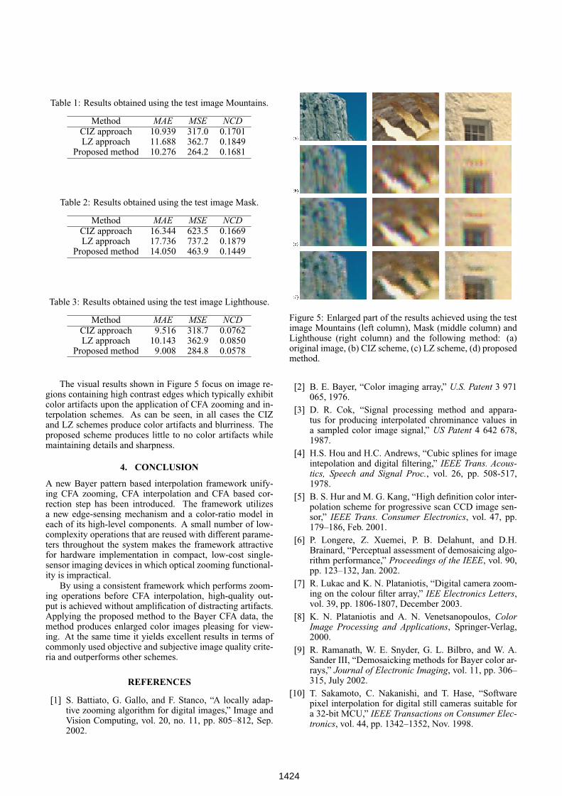
Table 1: Results obtained using the test image Mountains.
Method MAE MSE NCDCIZ approach 10.939 317.0 0.1701LZ approach 11.688 362.7 0.1849
Proposed method 10.276 264.2 0.1681
Table 2: Results obtained using the test image Mask.
Method MAE MSE NCDCIZ approach 16.344 623.5 0.1669LZ approach 17.736 737.2 0.1879
Proposed method 14.050 463.9 0.1449
Table 3: Results obtained using the test image Lighthouse.
Method MAE MSE NCDCIZ approach 9.516 318.7 0.0762LZ approach 10.143 362.9 0.0850
Proposed method 9.008 284.8 0.0578
The visual results shown in Figure 5 focus on image re-gions containing high contrast edges which typically exhibitcolor artifacts upon the application of CFA zooming and in-terpolation schemes. As can be seen, in all cases the CIZand LZ schemes produce color artifacts and blurriness. Theproposed scheme produces little to no color artifacts whilemaintaining details and sharpness.
4. CONCLUSION
A new Bayer pattern based interpolation framework unify-ing CFA zooming, CFA interpolation and CFA based cor-rection step has been introduced. The framework utilizesa new edge-sensing mechanism and a color-ratio model ineach of its high-level components. A small number of low-complexity operations that are reused with different parame-ters throughout the system makes the framework attractivefor hardware implementation in compact, low-cost single-sensor imaging devices in which optical zooming functional-ity is impractical.
By using a consistent framework which performs zoom-ing operations before CFA interpolation, high-quality out-put is achieved without amplification of distracting artifacts.Applying the proposed method to the Bayer CFA data, themethod produces enlarged color images pleasing for view-ing. At the same time it yields excellent results in terms ofcommonly used objective and subjective image quality crite-ria and outperforms other schemes.
REFERENCES
[1] S. Battiato, G. Gallo, and F. Stanco, “A locally adap-tive zooming algorithm for digital images,” Image andVision Computing, vol. 20, no. 11, pp. 805–812, Sep.2002.
Figure 5: Enlarged part of the results achieved using the testimage Mountains (left column), Mask (middle column) andLighthouse (right column) and the following method: (a)original image, (b) CIZ scheme, (c) LZ scheme, (d) proposedmethod.
[2] B. E. Bayer, “Color imaging array,” U.S. Patent 3 971065, 1976.
[3] D. R. Cok, “Signal processing method and appara-tus for producing interpolated chrominance values ina sampled color image signal,” US Patent 4 642 678,1987.
[4] H.S. Hou and H.C. Andrews, “Cubic splines for imageintepolation and digital filtering,” IEEE Trans. Acous-tics, Speech and Signal Proc., vol. 26, pp. 508-517,1978.
[5] B. S. Hur and M. G. Kang, “High definition color inter-polation scheme for progressive scan CCD image sen-sor,” IEEE Trans. Consumer Electronics, vol. 47, pp.179–186, Feb. 2001.
[6] P. Longere, Z. Xuemei, P. B. Delahunt, and D.H.Brainard, “Perceptual assessment of demosaicing algo-rithm performance,” Proceedings of the IEEE, vol. 90,pp. 123–132, Jan. 2002.
[7] R. Lukac and K. N. Plataniotis, “Digital camera zoom-ing on the colour filter array,” IEE Electronics Letters,vol. 39, pp. 1806-1807, December 2003.
[8] K. N. Plataniotis and A. N. Venetsanopoulos, ColorImage Processing and Applications, Springer-Verlag,2000.
[9] R. Ramanath, W. E. Snyder, G. L. Bilbro, and W. A.Sander III, “Demosaicking methods for Bayer color ar-rays,” Journal of Electronic Imaging, vol. 11, pp. 306–315, July 2002.
[10] T. Sakamoto, C. Nakanishi, and T. Hase, “Softwarepixel interpolation for digital still cameras suitable fora 32-bit MCU,” IEEE Transactions on Consumer Elec-tronics, vol. 44, pp. 1342–1352, Nov. 1998.
1424