bbc report - logo of the bbc
TRANSCRIPT
\ Research Department. REPORT No. Co 005. 11th January, 193?
Serial No. 193?L!
Inv~stigation by: Drawing No s : A.E.Barrett, D.B~WeigalL
i I
!
C.005.1 to C.005.8
REPORI' ON UTVESTIGATIONS LEADING TO
PROVISIONAL MODIFICATIONS TO MARCONI-STILLE EQUIPMENT
I SUMMARY.
I
M MAIDA VALE.
This report describes the results of experiments which led to the increase of signal-noise ratio. Some of the factors which must be considered when determining the optimum recording characteristic are mentioned. Three arrangements of the pole pieces in the reproducing head are compared, the single pole piece arrangement being adopted for use at Maida Vale. The report concludes with a description of the modifications made to the equipments in service.
IUIMliiiiillil 300008844 R
, t_,,;;
(ii )
(Hi)
-2-
Object of Investigation.
Method of Approach.
Determination of maximum Recording Level at any frequency.
AmplifieFs used.
Experimental methods used.
Variable factors affecting maximum recording levels.
(iv) Final Choice of Recording Characteristics.
(v) Methods of Reproducing to give Highest Signalnoise Ratio.
Two Pole System: Pole pieces staggered.
Two Pole System: Pole pieces opposite one another.
Single Pole System.
(vi) Frequency Characteristic of Reproducing Amplifier.
(vii) General Conclusions.
Appendix. Modification to Equipment.
, 1
!' :
-3-
( i ) OBJECT OF INVESI'IGATION.
To effect a temporary improvement to tide over the period of a
further investigation.
This improvement should involve as little fundamental change as
possible to existing apparatus, so that it could be carried out
innnediately. By such improvement it was hoped to increase the signal-
noise ratio, to improve the frequency response and, if possible, to
reduce the non-linear distortion.
( ii ) METHOD OF APPROACH.
In order to obtain the highest possible signal to noise ratio
from any system, it is necess~J to adjust the frequency characteristic
of the programme input to the system, so that at any frequency the
maxtmum level of programme will bear a suitable relationship to the
maximum permissible level to the system.
Thus to choose the best possible recording characteristic to
use, it is necessary to decide upon two points. The first is the actual
maximum level which may be applied in practice to the recording head at
any frequency. The second is the energy distribution as a function of I
frequency of the programme to be recorded.
The first point must be investigated by experiment. As regards
the second, the evidence is largely statistical. Time was not available
for a complete analysis of a large number of different types of prograrmn8"
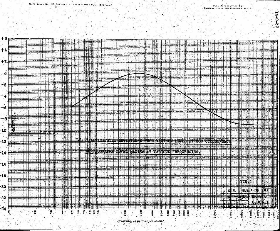
As a basis for experiment, a curve was taken from a paper by Harvey
-4-
Fletcher, published in the Bell Technical Journal, Vol. X, No. 3, of the
maximum amplitudes encountered at any particular frequency for an I
orchestra playing a typical work. A modified version of this curve is
reproduced in Fig. 1.
In practice it would, appear that in the majority of programmes
the maximum ffinplitudes occur at frequencies between 200 cycles and 500
cycles.
Time was not available for a complete investigation into the
causes of ground noise, but experiments were carried out in order to
discover the effect of the shape and adjustment of pole pieces, and the
variation of the saturation and demagnetisation currents. Further
experiments on the causes of ground noise are at present in hand.
(iii) DETERMJNATION OF MAXIMDM RECORDING LEVEL.
It is extremely difficult to fix a definite value for the
maximum permissible recording level at any frequency. One of the chief
difficulties is that owing to the high level of surface noise, and the
variation of speed of the tape, resulting in an ,inconstancy of frequency,
it is not easy to measure either percentage harmonic content, or the
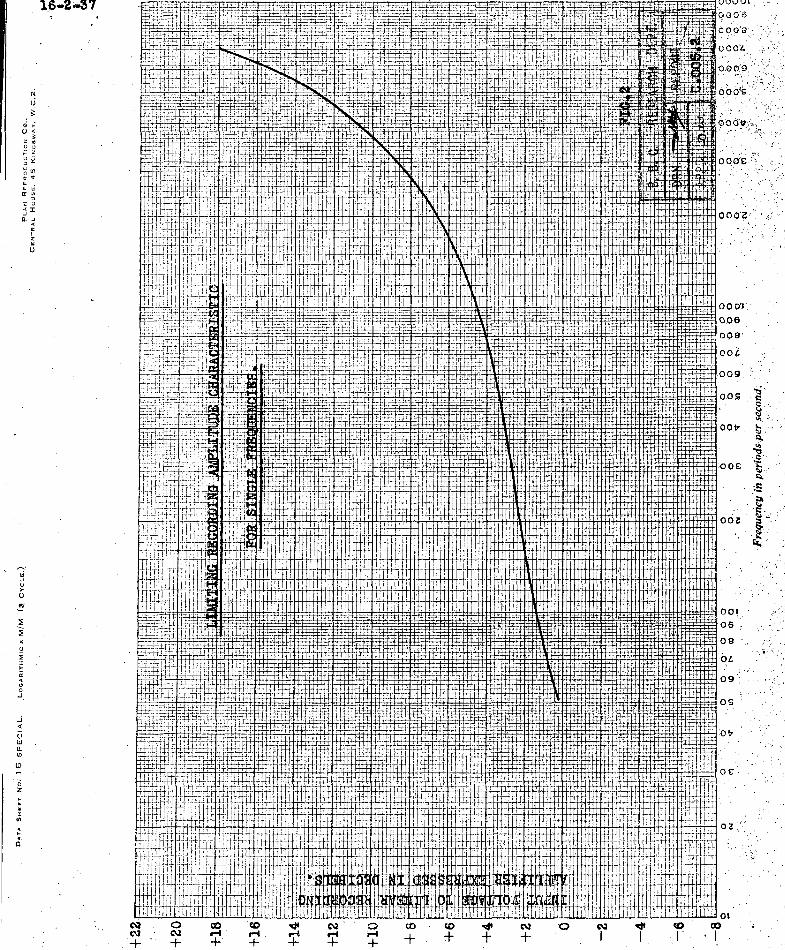
levels of intermodulation tones. In practice, the maximum permissible
recording level was taken as the lowest level at which there occurred
some definite indication of amplitude ,distortion by any of the methods
used, as described later. The resulting curve is shmm in Fig. 2.
-5-
~plifiers used_~~~ Tests.
The output impedance of the recording amplifier was approximately
40 ohms, feeding the recording head, which had a D.C. resistance of 150
ohms, and an inductance of about 0.1 hy. The amplifier thus always fed
into an impedance that was high compared with the output impedance. The
frequency characteristic of the uncorrected amplifier was sensibly flat
up to 10 kilocycles.
The frequency characteristic of the reproducing amplifier was
also flat up to 10 kilocycles.
Experimental Methods Used.
Various methods were used to indicate amplitude distortion.
(1) The reproduced w8.veform was examined using a cathode-ray oscillograph.
(2) Listening tests were carried out using pure tones. The method used was to reduce the input level and increase the output level by 20 dB. at the same moment. By this method the presence of harmonics or departures from amplitude linearity are shown up surprisingly well at the medium and lower frequencies.
(3) Amplitude characteristics were taken using a test programme meter, the reproduced level being plotted against recording level. This method was found to give consistent result s which agreed reasonably well with the results of the other methods at the middle and lower frequencies.
(4) For certain tests a 1500 cycles high pass filter was used to cut out the fundamental frequency of the reproduced tone, and the harmonic content was approximately calculated from the resulting change of level, as indicated by a programme meter, on switching in the filter.
-6-
Variable factors affecting maximum recording levels.
The main factors affecting the maxirmun recording levels for a
given tape and type of recording head are the shape and adjustment of
the recording pole pieces and the working point on the hysteresis loop
which is determined by the saturation and demagnetising systems.
~cording Pole Pieces.
It is not easy to obtain very conclusive results regarding the
effect of pole-pieces. Unless the whole width of the edge is in contact
wi th the tape, overloading is likely to occur at the actual point of
contact long before the normal overloading point is reached. Such a
state of affairs may be due to an inaccurately ground pole piece, to dirt
or a slight burr, or to wear of the pole piece guide forming part of the
recording head.
The problem is also complicated by the effect of the stray field
from the pole pieces as distinct from the direct field in the tape
between the two pole pieces. In the simple theory of steel tape
recording, it is the latter field alone which has been regarded as the
most important. Recent experiments have indicated that stray field from
the second pole piece passed by the tape is largely responsible for
recording.
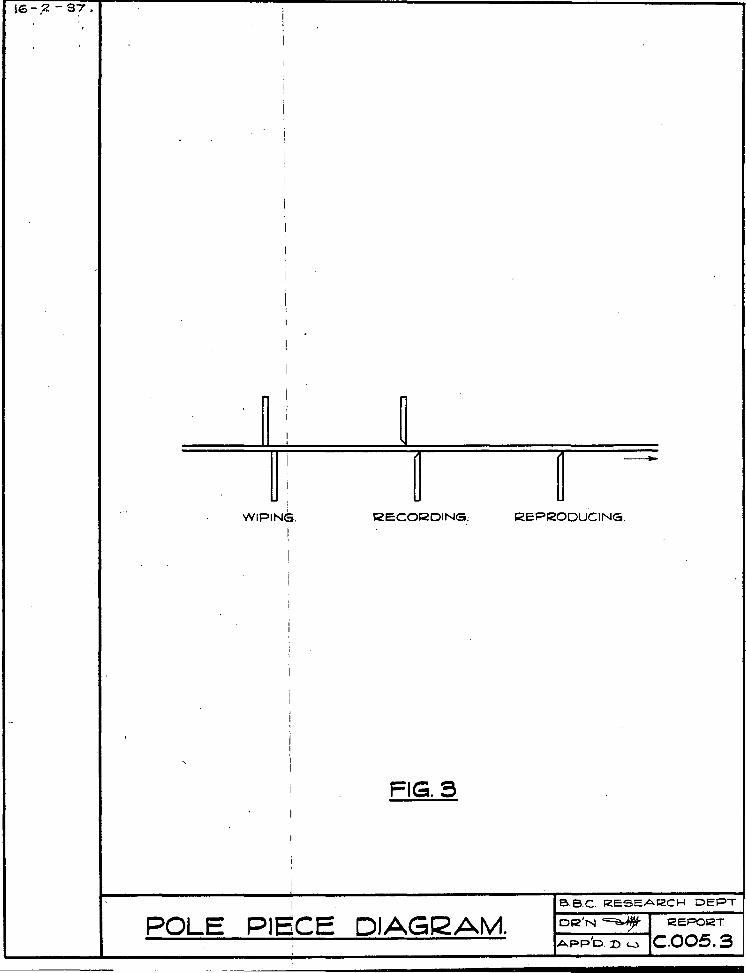
Associated with the effect just described is the fact that
improvement has been obtained by reversing the direction of the tapered
edge of the second pole piece as illustrated in Fig. 3. The new
-7-
arrangement is now standard practice.
With regard to the sharpness of the pole piece, a compromise must
be adopted. The sharper the pole piece, Le., the smaller th:e flat , the
less will be the attenuation of the higher frequencies. On the other
hand, wear may be very serious as the tape runs through, and the passage
of a joint th~ough the recording head will have a very much worse effect
than with a blunt tip. In addition, saturation effects in the tip may
occur with a sharp pole piece.
Wo!king Point on HYsteresis LooV.
The working point on the hysteresis loop is determined largely by
the value of the direct current component in the recording head. The
optimum value of this current is not the same for all frequencies;
further, the value chosen has a slight effect upon the reproduced noise
level.
A compromise must be made, therefore, in the choice of this value,
and that previously in use, i.e., about 3.8 milliamps. appears satisfactoryo
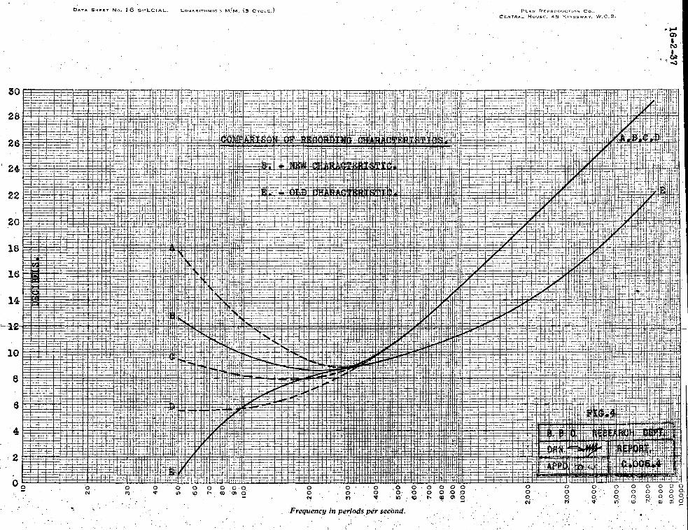
(iv) FINAL CHOICE OF RECORDING CHARACTERISTICS.
The maximum recording level as a function of frequency (Fig Q 2)
was determined under what appeared to be the most satisfactory working
conditions. This was expressed in the form of the voltage applied to
the grids of the output stage of the recording amplifier. With this
was combined the inverse of a somewhat conservative version of the
maximum amplitude-frequency characteristic of an orchestra. The-
-8-
resultant curve was taken as a possible recording characteristic, and is
shown in Fig. 4(b).
This curve rises more sharply towards the higher frequencies than
the previous recording curve, and instead of falling away in the extreme
bass, actually tips up. As previous results had apparently tended to
show that blasting was liable to occur in the bass sooner than elsewhere,
correction circuits were deSigned for the recording amplifier which would
give varying degrees of bass tip.
The best possible recording characteristic is to a certain extent
dependent upon the method of monitoring for control purposes.
If a really satisfactory visual monitoring system is practicable
and can be made to indicate the maximum permissible runplitude in all
frequencies, it is then possible to use a recording frequency character
istic such that overloading is likely to occur equally at all frequencies,
when the amplitude frequency characteristic of the voltage applied to the
amplifier is similar to that existing in a normal transmission of music.
If, however, this cannot be arranged, a recording frequency
characteristic is desirable such that overloading of the lower frequencies
occurs before the higher frequencies. Aural control is then possible,
attention being concentrated on the lower frequencies, and the result of
an overload of this kind is less objectionable than when overloading
occurs simultaneously at all frequencies.
The curve shown in Fig. 4(b) was actually adopted after experiment,
alternative curves which were tried being shown by the broken lines
-9-
(A, C, and D). Fig. 4(e) shows the old type of characteristic for
comparison,
(v) 1lET:[ODS OF REPRODUCING TO GIVE HIGREm' SIGNAL-NOISE RATIO.
A frequency characteristic for recording having been chosen, such
that the maximunl possible level may be recorded at all frequencies, the
next step was to decide upon a reproducing system which would give the
highest possible signal-noise ratio. Three systems were tried.
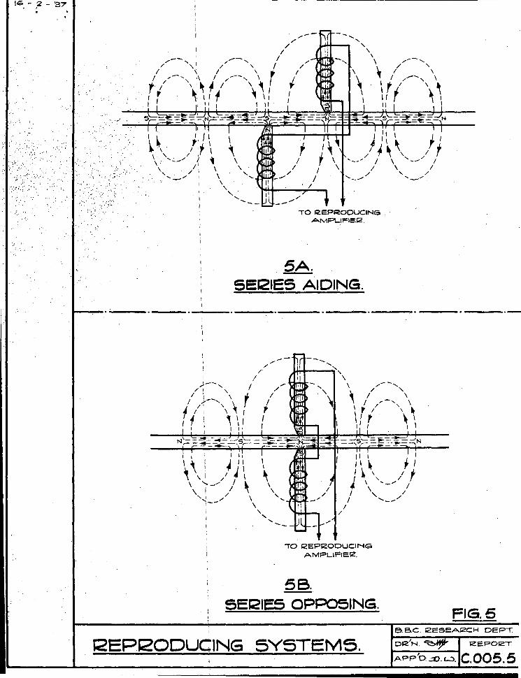
Two Pole System: pole-pieces sta§.8er~d.
Wi th this system the gap between the pole pieces measured in the
direction of the run of the tape is adjusted to be approximately equal to
half the wavelength of the highest frequency to be reproduced. The coils
on the reproducing pole pieces are connected in 11series-aidingH , and the
nett e.m.f. induced in the tvm coils will be proportional to the
difference between the rates of change of flux through the two coils.
For long wavelengths this difference will be small, so that low
frequencies will be very considerably attenuated by such a method of
reproduction. This is shown diagramatically in Fig. 5(a).
A reproducing characteristic has to be used which will attenua"te
the higher frequencies to compensate for this. As a result, the lower
frequency components of ground noise become most important, and no
appreciable improvement can be effected by a 5000 cycle low pass filter.
-10-
~Pole System: ]?ole-]2ie.ces exactlx. opposite.
In this case the coils are connected in l'series-.opposing71 , so
that the nett e.m.f. will be equal to the sum of the e.mof1s generated
in each coil and proportional to the rate of change of flux through the
coils. The llseries-opposingll connection is due to the fact that the
flux passes th~ough the two coils in opposite directions.
With this method the reproduced level is not greatly changed at
the higher frequencies, but the level at the lower frequencies is very
much greater than in the previous case, as the low frequencies are no
longer attenuated. This arrangement is shovm diagramat ically in F:Lgc
5 (b).
In order to obtain a straight frequency characteristic, the
higher frequencies have to be tipped up in the reproducing amplifier, so
that the nett gain in signal-nOise ratio by this method will be
comparatively small at the higher frequencies, corresponding actually to
the difference in the efficiency of the two methods of picking up noise.
At the low frequencie s, however, the gain is very considerable. The
consequence is that ground noise is reduced to a hiss.
One advantage of this method is that there is no definite upps::'
limit to the frequency range, although by deliberately cutting off at
between 5000 and 6000 p.p.s., a very appreciable reduction of ground
noise is obtained.
The main 'disadvantage of this system is that it requires extremely
accurate adjustment. In order to obtain a reasonably flat frequency
•
-11-
characteristic, the two pole pieces must be exactly opposite each other.
Under service conditions, with varying pole pieces and worn pole-piece
guides, it would be practically impossible to ensure that this was always
the case throughout the whole of a reproduction.
Single Pole Sy~tem.
The operation of this system is almost exactly the same as that
using two poles opposite one another. The removal of the second pole
piece is liable to lead to a slight loss of 'top' since, with the two
pole pieces, the flux is slightly more concentrated. In spite of this
the background noise is lower than with the two staggered pole system.
It has another advantage which is of some importance in practice. With
the two pole system it is necessary to adjust the setting of the
reproducing head by ear. This is not very difficult when recording,
but when reproducing a programme that was recorded some time previously,
it is extremely difficult to get exactly the correct setting. With the
single pole system, however, no such adjustment is necessary. It was
decided to use this system and to design the correction circuit for the
repro duc ing amp lif i er a cc ordingly •
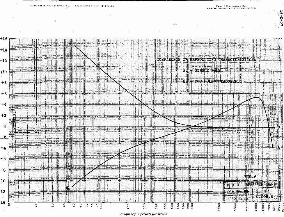
(vi) FREQ,UEl'ICY CFf...ARACTERIsrIC OF REPRODUCING AMPLIF.rE~:
In determining the frequency characteristic of the reproducing
amplifier, the main factors to be considered are the best compromise
between surface noise and frequency range, and the shape of the
-12-
reproducing pole piece, It was found tliat to. cut off the higher
frequencies above 5000 cycles gave a satisfactory balance of frequency
range and ground noise when pole pieces of the same a~ape as the recording
pole pieces were used. The characteristic used is shown in Fig. 6(a),
with the old curve shown in Fig. 6(b) for comparison.
(vii) GENERAL CONCLUSIONS.
The present system appears to be more dependent upon pole piece
variation than the previous system. This is probably because previously
it was possible to compensate for the change in frequency characteristic
resulting from poor pole pieces to a certain extent by adjustment of the
heads, and poor quality recording was not sho.Vil up as vividly as at
present. As a result, R more consistently high standard of recording
should be possible. It is definite, however, that pole pieces must be
very accurately shaped to give good results.
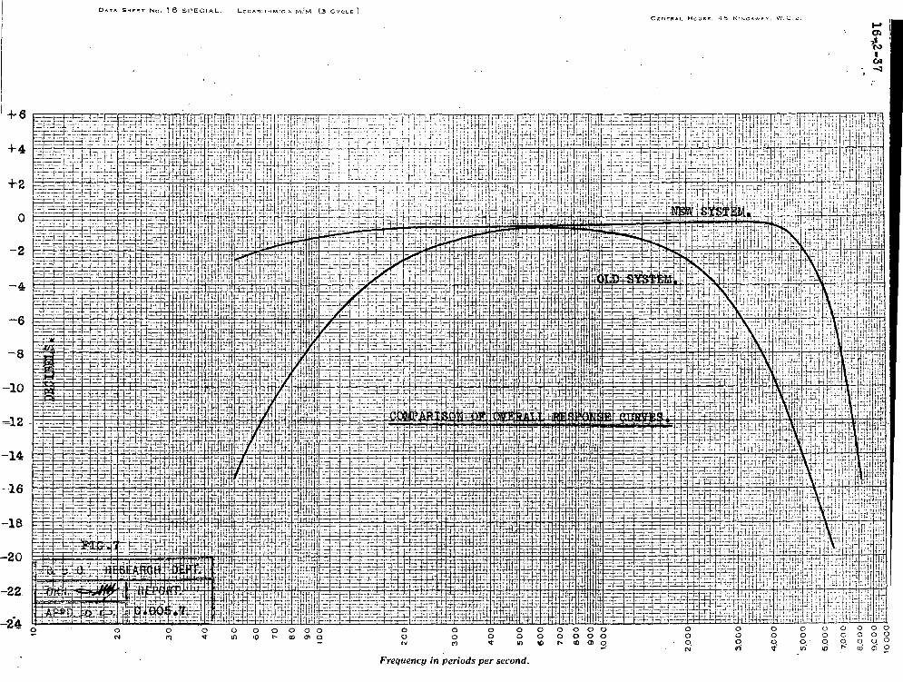
The overall frequency characteristic of the system from the input
of the recording amplifier to the output of the reproducing amplifier is
shown in Fig. 7, in which it is compared with the original characteristic
obtained before the alterations described were made.
Actual measurements upon a given tape show an improvement of 10
dB. in the signal-noise ratio on changing over from the old to the new
system; the actual noise figures were from 24 dB. to 34 dB. below
programme level, measured on a programme meter.
Figure 1.
Figure 2.
Figure 3.
Figure 4.
Figure 5.
Figure 6.
Figure 7 ..
Figure 8.
-13-
LIST OF FIGURES.
Least anticipated deviations from maximum level at
300 cycles of programme level measured at various
frequencies.
Limiting Recording Amplitude Characteristic.
Pole Piece Diagram.
Comparison of Recording Characteristics.
Reproducing Pole Piece Systems.
Comparison of Reproducing Characteristics.
Comparison of Overall Response Curves.
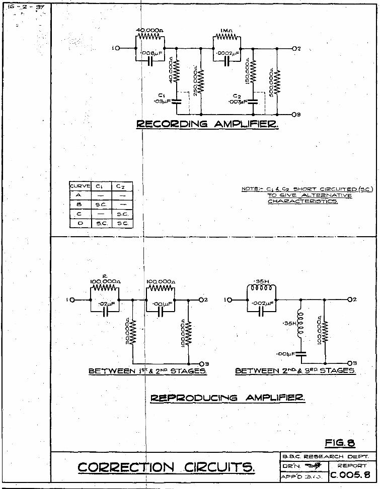
Correction Circuits.
-14-
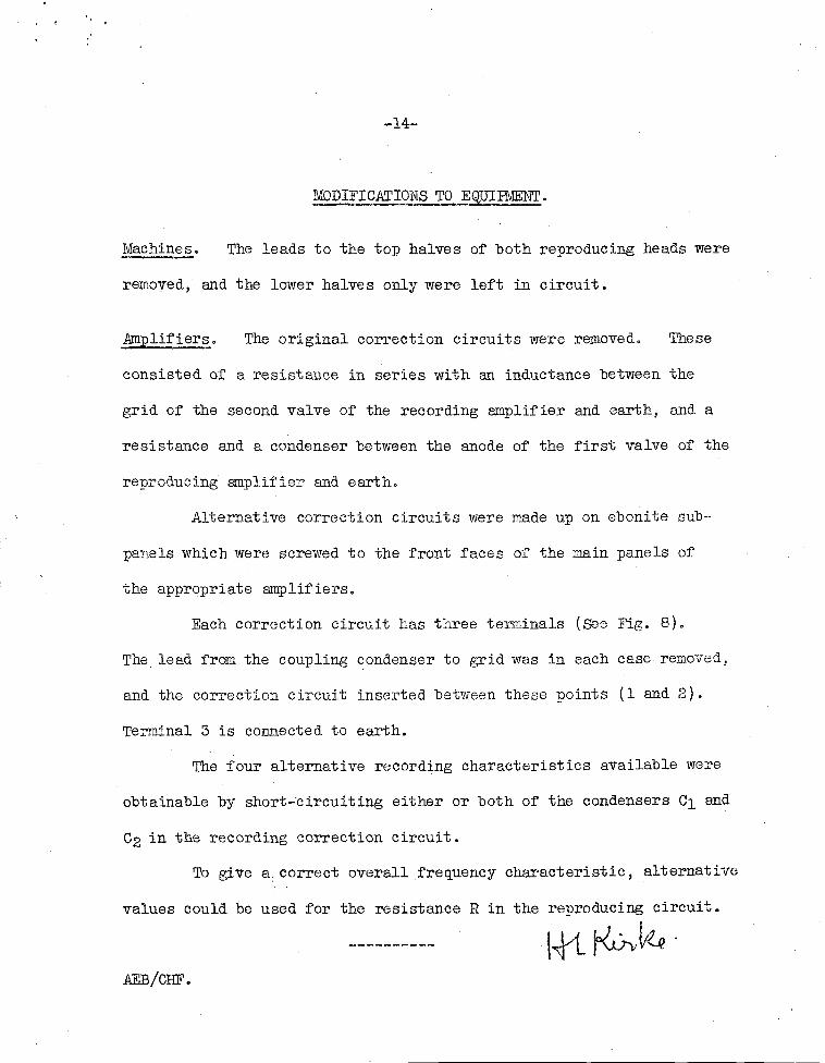
~ODIFICATIONS TO EQUIPMENT.
Machines. The leads to the top halves of both reproducing heads were
removed, and the lower halves only were left in circuit.
Amplifiers. The original correction circuits were removed. These
consisted of a resistance in series with an inductance between the
grid of the second valve of the recording amplifier and earth, and a
resistance and a condenser between the anode of the first valve of the
reproducing amplifier and earth.
Alternative correction circuits were made up on ebonite sub-
panels which were screwed to the front faces of the main panels of
the appropriate amplifiers.
Each correction circuit has three terminals (See Fig. 8).
The. lead from the coupling condenser to grid was in each case removed,
and the correction circuit inserted between these points (1 and 2).
Terminal 3 is connected to earth.
The four alternative recording characteristics available were
obtainable by short-circuiting either or both of the condensers Cl and
C2 in the recording correction circuit.
To give a. correct overall frequency characteristic , alternative
values could be used for the resistance R in the reproducing circuit.
\+1-~'~ . AEB/CHF.
-20
-22
.. ~.
" .~ .
'bAT,. SHEET No. 16 .SPECIAL. f::,09A'RITHMIC'X M/M. (3 'CY~LS:.) •
o " N
o ,0 0 ""Cl) 010
,- o '0 ,0 0 -t, III
, Frequency;n per{ods.'persecond. . " , (. ~ . c.... -: .
PLAN R£PRODUCTION CO .•
<?EN7"RA·L:HoUSE. 45 KINGSWAY. W.C.2.
o o
, ,~':
N
U si
cl .;. U <
~ Z • C 0 ~ Z
g~ 011)
g" .. • W It •
o z 0 j 1: It -'
< < f. Z .
~.
,; -' o > u .!! ::> 1" ~ ~ z t < < o o .J
j .: u w It
'" to
c z f. · · r
III
· f. .. o
U
lp-20.37 00091
-··+····~£:[~li~f~f;JTl I ltG .. ;O·6 OO.O·g
~}±fFr
""PI
f " 'n n' It
OOO·/.
O'g --.\
666'1: ..
~~q~+T -.• ~. "ooO·~.';;.
ffi f ~B'!HIft;-f ... H+
~i{~~f itl:T lTiIVrtfRtllfI+jfh.
. it, I) T! ,,1 'hh-';"1.4tr
11
: mf+l+lffm:~~!+J+lj+~f H+j~4+t~i+f-l~+++J-H.!+J\!'I-P-i+4}f+++1t ~l-l+HJl-H-H+H+i+l-I-++i-I+Hj-HW + W-l+i-~+JI!-4~W~l d.,Hi,-I'i·H;;-"-"+
F+i
r;.:-;
'1\
f-f
I:fT ~1-
-t·~· 1.-
:nr
'T' re-
fF
f:I:
lTfjjltt~~:~ fH.ITm:. ~ 11~: it~~' I~i~ ~11T ·~·~m~1mt-.. I;ti: ~:H~tl :Ifttttl+t~t' :~~+l~I'::::~~;;;;:w[' ~n;:titll: IttlilIlIWtttttt· ,,!-H. +tttt
f
ttU r" l[t! I IJ I ' I i" 11 ill' ,m '11 lIT I t' I ; let L II!I I'll '1 I:] I rt I i JI I .' . I
I,H-1trltl' '[I 'I 'f- +lli'h -I t'll'l I' I ·~H h· I-Ht-. i.rt-c ,: 4-H !-l.j..-!-i+,i H' . . " . ..' . .. . + 1/11,1 1, ,illl 11,111, I, ,I. 1,,1 ,11.1,:,
~~}f f~i-t$
~+l-Hi'i 'J+t' i+WtU" t-tml:tT+ :i;~]T; tl :" Fp··· !-;-H±l:.t-2" ~h+t-!+ri- t- ,.-t+ ;.::; ~:::;;-'.:.;:t-~"::.:.:-..:::i_'
-[tl~:P:···-
FT
, - ',).':, .. "": " :.'
QOO'Cr:
oOO'Z'
0.06
oos·
00l.
009
0010 ~. <::>
~.
00l> 1;;.' t4
~ ·0"
O€: '5 t4
.s::
OO~
06
09
OL
09",
os
:017
.~
l t· ~.,.
'·'r
lliffi~ffiffiililli~llilliffifflmffiffifrlliillmillillillffillimffiftlli~ffillimmmm~~tr:~mmmm~oz
N N +
I ; ~-"~oo pj.~~ml-I-i-I.j·W~·+il~-iilli-+j-f Q·U-4Hri-l
Nli:oo~~~rnJ.l,~Idri""ifi-f-j,~J.H+~d-tittitn' ~ -:1 )! H t! I i!! I j i I! II! 11 i: j r J lit i II1 i I1I Uli! j II! Ill!! I! j·f 01
~ ~ ~ N 0 ro NON ~ ~ ro ~. .~ ~ !f ~ + + 1 I I'· I
,,': .',
l6-.2 97.
11
'!
!i
il
11
!!
ii
11
I
11
!I
11
1'
11
i!
!I
~ !I
~ 11
i!
"
~I ~ ~ -i
11
WIPINJ;. I<ECOI<DING, REPRODUCING. 11
I'
11
1I
" I,
" 11
"
\
,
11 FIG.S 1
11
ii
ii
I1 BB.C. RESEA12CH DEPT
POLE PIECE DJAGf2AM. DI<'N~ 12 EPO 12T
APP/D. D <....) C.OOS.3 I
O",TA SHEliT No. 16 SPECIAL. LOG .... RlnlMlc x M/M. (3 CYCLI¥=J PL~N REf'Fl('lOVCTI{,)N Co .. CeNTRAL. HOUSE. 45 KING$WAY. W.C.2.
.':'
.. ',' .
':'
'. '.'~ '. ".' . ,
,-'.
//--", I!
/ ~
,. I1 ~' 1
I if \ / ,I
-/ ( " I: \ " /' '.:-" \ .. \ , , ................ _-
11 1 J '\ ~ f I
/~~, /t "" / \ '-- /
/ \ / ........ _----/ ' ...... _//
TO J<EPI20DUCIN6 AMPLIFIEI2.
5A. Sef2IES AIDING.
1 , 1 I,
\ \ ~ 11 \
"I IJ\ ~ \".,// .. '\ \ 1'- I '\ \ '-! ,,/ \ "
1'-- \ , "- ....
-"" /
/
/
J\ I 1 , \ ~ ~ I , ~ \ I f I \ " ",,/ ~ - /
\ / / "-_/ I
TO I<EPI<ODUCIN6 AMPLIFIEIZ.
58. SEr2IES OPP05ING.
k2EPJ20DUCING 5YSTEMS.
+16
+14
+12
+10
+8
+6
+4
+2
o
-4
-6
-8
-10
12
14
OA.TA. SHEF.T No. 16 SPECIAL. LOGARITHMIC X M/M. (3 CYCI..Ii:.)
o 0 0 0 '.Of'aJO')O
o o N
o o ot
o o 10
Frequency in periods per second.
PLAN R£PR'nt1uCTION CO •.
CENTRAl.. Hou~r,:. 45 t<1~(~~WAY. W.C.2.
o ,.)
O .. TA Sl-tEl!;l" No. 16 SPECIAL... LOGAf"<lTHMJC)" M/M (3 CYCLfi:.) CCNfRAI. HouSI!. 45 Kl~JOtiVl"Y. 'wV r......d..
1+ 6
+4
+2
-6
-8
-10
=12
-14
-16
-18
-20
-22
Frequency in periods per second.
IG - 2 - 37 . ,.... . ... 1"', ~'"'
j .
,-UICVE Cl C'Z
A - -B SC. -C - S.C.
0 S.C. S.C.
il
'11
I 4O,OOOn
11
I '11
I,
II Cl
11 ·09).LF
11
--, 1 1 1 1 1
r2ECOI2DING
IMn.
8 o (j
--, 0 1
10
1 1 1
AMPLIFIEI2.
NOTE:- Ct &.. C2 SHOI2T CII2CUITED (5.c) TO GoIVE. AL TEI2NATIVE CHA12ACTE1215TICS
______ ll . '--' '1'-'--'--'--'--'---'-'-'
12. 100.000n.
Cl o
1I
1
8 '~I gli I,
ioO,ooo.n
...--__ ---c:)'2
Cl
8 o (j Q
1I • 9 BETWEEN Is;r.& 2 ND. STAGES.
\
1.---.4-..,..--09 BETWEEN 2 ND.& 3 I<! D. STAGES.
r2.eF=-~ODUC'NG AMPLIFISJ2.
1I
C0I2J2ECliIONCU2CUIT5.
FIG.e 6.B.C. RESEARCH DEPT.
DI2'N~ ~ I2EPol2T
pb :i>.l-.J. C. 005. S