bce final notes dbacer
DESCRIPTION
built environmentTRANSCRIPT

1
UNIT – I
INTRODUCTION SCOPE OF CIVIL ENGINEERING
INTRODUCTION:- Civil Engineering is the oldest branch of engineering which is growing right from the stone-age civilization. American Society of Civil Engineering defines civil engineering as the profession in which knowledge of the mathematical and physical sciences gained by study, experience and practice is applied with judgment to develop ways to utilize economically the materials and forces of the nature for the progressive well-being of man. In this chapter various civil engineering infrastructure projects for 21st century are listed and the role of civil engineer is presented. Apart from civil engineering there are other infrastructural facilities required by the public which need coordination with other engineers. Importance of this interdisciplinary approach in engineering is also presented in this chapter. SCOPE OF CIVIL ENGINEERING:- The world has realized that a government should not involve itself in production and distribution but develop infrastructure to create an atmosphere for economical development. Civil Engineering activities in the infrastructure development are as under: 1. A good planning of towns and extension areas in the cities is required. Each extension area should be self-sufficient in accommodating offices, educational institutions, markets, hospitals, recreational facility and residential accommodations. 2. Fast rate of urbanization and increase in the cost of land has forced civil engineers to go for vertical growth in cities. In metropolitan cities, 25 storey buildings have become common. Even in small towns multi-storey buildings have become necessity. These requirements have brought in new building technologies and sophisticated analysis methods. Civil Engineers have to solve the problems of rural areas and poor people also. Low cost housing is the need of the day to make poor people afford their own houses. 3. Water is an important need for all living beings. Civil engineers have to exploit various water resources and ensure water supply to urban areas throughout the year. Rural areas need water for agriculture also. Hence civil engineers have to build dams and tanks and bring water to houses through pipes, and to fields through canals and distributaries. 4. Another important amenity that public require is good roads. Design of appropriate base course thickness, finishing surfaces, cross drainage, design of horizontal and vertical curves are the duties of civil engineers. Proper design of intersection of roads is necessary. Construction of culverts, bridges and tunnels became part of road works. Railway is an important long distance facility. Construction of railway lines and railway station is an important infrastructure activity. Globalization has resulted in need for building airports and harbors also. 5. Other important infrastructural activities of civil engineering are controlling air pollution, noise pollution and land pollution. ROLE OF ENGINEERS IN THE INFRASTRUCTURE DEVELOPMENT:- A civil engineer has to conceive, plan, estimate, get approval, create and maintain all civil engineering infrastructure activities. Civil engineer has a very important role in the development of the following infrastructures: 1. Measure and map the earth’s surface. 2. Plan and develop extensions of towns and cities. 3. Build the suitable structures for the rural and urban areas for various utilities. 4. Build the tanks and dams to exploit water resources. 5. Build river navigation and flood control projects. 6. Build canals and distributaries to take water to agricultural fields. 7. Purify and supply water to needy areas like houses, schools, offices etc. 8. Provide and maintain communication systems like roads, railways, harbors and airports. 9. Devise systems for control and efficient flow of traffic. 10. Provide, build and maintain drainage and waste water disposal system.

2
11. Monitor land, water and air pollution, and take measures to control them. Fast growing industrialization has put heavy responsibilities on civil engineers to preserve and protect environment.
GENERAL CONCEPTS RELATED TO BUILDING SELECTION OF SITE:- The selection of a site for affordable housing should reflect the particular needs of the population that your housing development will serve. An important consideration is the location of the property in relation to the services residents will need to access, such as shopping, medical, schools and transportation. A steep piece of property is generally not suitable for elderly or physically disabled residents. Location of the site may also have a significant impact on the cost of your project. You will have to strike a balance between meeting the needs of your residents and the final location of your project The shape, slope and soil conditions of a piece of property will all have an impact on the practicality of development. An odd-shaped lot may present design challenges and the cost to remediate a polluted site will have a serious impact on project viability. The availability of services to a site is another important consideration, as it is expensive to bring or upgrade water, sewer, power and other utilities, as well as roads and sidewalks, to a piece of property. There are many factors which must be taken in to account while selecting a site for a commercial and residential buildings. Some of these factors are given below.
1. Shape of the Plot 2. Location of the plot 3. Availability of amenities 4. Water Table 5. Sewerage system
1. Shape of the plot: Geometry of the plot for any kind of construction is very important which can largely affect the appearance of your structure. Shape of the plot should be such that the construction can be easily made with cost low as possible. And also in the future you can further expand it. A plot with more routes will be considered a good one. 2. Location of the plot: The surround area of the residential plot is very important. It effects the price and the beauty of the plot. Plot should be taken in the area provided with a lot of services. And in a suitable environment free from all kind of pollutions. Efforts should be make to buy it near to main road. Because such plots are more valuable as compared to the plots situated away from the main road. 3. Availability of Amenities: Plot for a residential building should be taken in the area provided with much number of amenities. Such as electricity, Telephone, Fax, Internet, Gas, School, Colleges, University etc. and the most important is the good and fast transport system. So that communication becomes more fast and quick. 4. Water table: The water table at the site of residential building should not be very high. Otherwise it will affect the quality of water which is used for drinking and domestic purposes. A plot with normal water table will be more preferred as compared with other plots having high water table. 5. Sewerage System: There should be proper sewerage system at the site of residential plots. So that the extra water of houses can easily be drawn out especially in rains and floods. If in case there is no sewerage system the dirty water effect the building and as well the occupants as well. BASIC REQUIREMENTS OF BUILDINGS: The design and performance of a good building should satisfy the following basic requirements: 1. Strength and stability: The structure should be stable to resist all the loads i. e. dead load, live load, and wind load. Building should be capable of transferring the expected loads in its life period safely to the ground. Design of various structural components like slabs, beams, walls, columns and footing should ensure safety. None of the structural components should buckle, overturn and collapse. To achieve strength and stability of building, proper load factor should be applied while designing a structure. 2. Dimensional Stability: Excessive deformation of structural components gives a sense of instability and result into crack in walls, flooring etc. All structural components should be so designed that deflections do not exceed the permissible values specified in the codes. 3. Resistance to Dampness: Dampness in a building is a great nuisance and it may reduce the life of the building. Great care should be taken in planning and in the construction of the building to avoid dampness. The presence of moisture in any building deteriorates the strength of materials and results in reduction in

3
durability. In order to prevent the entry of damp into a building, damp-proof courses are provided at various levels. 4. Resistance to Fire: To protect the building against fire, composite and noncombustible materials should be used in the construction of walls, columns, beams, etc. Also standards of fire safety or fire extinguishers as specified in the building codes should be provided with sufficient and quick fire exit. Regarding achieving resistance to fire, the basic requirements laid down in the codes are: (a) The structure should not ignite easily. (b) Building orientation should be such that spread of fire is slow. (c) In case of fire, there should be means of easy access to vacate building quickly. 5. Heat Insulation: A building should be so oriented and designed that it insulates interior from heat. To achieve heat insulation requirements for different types of building, one or more following means should be adopted : 1. In the construction of cavity walls, roofs, floors, etc. to fill air spaces in construction materials, heat insulating materials like slag wool, light weight concrete should be used. 2. The buildings should be provided with chhajjas, canopy, weather sheds, verandah, courtyards, tress, garden etc. to achieve heat insulation. 3. Top terrace of the building should be insulated against heat insulation against heat economically by using special flooring method. 6. Sound Insulation: Buildings should be planned against outdoor and indoor noises. It is necessary to give attention to the sound insulation of buildings because of various factors such as increase in population, change in habits of community, increase in noise pollution, improvement in building construction practices, etc. The function of sound insulating construction is to reduce the sound passing through it. Generally hard materials are used for sound insulating construction. 7. Protection from Termite: Termites are known as white ants as they are no related to ants. The termites live in colony and they are very fast in eating wood and other cellulosic materials as food. The cellulose forms their basic nutrient. They also damage household articles like furniture, furnishings, clothing, stationary, plastic, leather, rubber etc. for the removal of termites from the building adopt pre-construction techniques of termite-proofing. The post construction treatments of termite proofing consist of opening earth around the building and treating it with chemicals; drilling holes in damaged portions of masonry and woodwork and injecting chemicals under pressure. 8. Durability: Period of time up to which the building remains habitable is called its durability.
1. Durability of a building depends upon following factors: 2. Degree of maintenance 3. Method of construction adopted 4. Types of materials used in building. 5. Exposure condition to weathering which is determined by the climate environment, site, aspect and
height of building To increase and maintain durability of a building following steps should be taken
1. Proper features like projecting eaves, copings, sunshades, parapets, sills etc. should be provided in building to prevent from rainfall, sunlight, moisture and other exposures of weather.
2. Proper care is to be taken in designing a building, in maintenance of building, in choice of materials and in the protection of a building against weathering effects.
9. Security against Burglary: For the safety of building, the external walls should be strong enough. Also window openings should be protected with M. S. grill or concrete jail or by any other means. In important buildings where high security is required, automatic alarm system is also provided. 10. Lighting and Ventilation: For healthy and happy living natural light and ventilations are required. In every building position, number and sizes of doors and windows should be such that sufficient day light free from glare comes from the right direction. Sufficient daylight should reach in every room of building, to create pleasing environment to work and to live. Ventilation in the building means passage of clean air in a building. Hence windows or openings should be provided on the opposite sides to facilitate cross ventilation.
TYPES OF BUILDING:- Building is defined in many aspects as: As a Civil Engineering structures such as a house, worship centre, Factories etc. that has a foundation, wall, roof etc. that protect human being and their properties from direct harsh effect of weather like rain, wind, sun etc.

4
I) RESIDENTIAL BUILDING:- Residential buildings are called houses/homes, though buildings containing large numbers of separate dwelling units are often called apartment buildings or apartment blocks to differentiate them from the more 'individual' house. Building types may range from one-room wood-framed, masonry, or adobe dwellings to multi-million dollar high-rise buildings able to house thousands of people. Increasing settlement density in buildings (and closer distances between buildings) is usually a response to high ground prices resulting from many people wanting to live close to work or similar attractors. II) PUBLIC BUILDING:- (i) “public building” means any building- (a) Used as a- (i) School (including a tutorial school) or college (including a tutorial college) or University or other educational institution; (ii) Hostel; (iii) Library; (iv) Hospital, nursing home, dispensary, clinic or maternity centre; (v) club; (vi) Lodging house, boarding house or hotel; or (vii) choultry; (b) ordinarily used for public meetings or for celebrating marriage functions III) COMMERCIAL BUILDING:- A commercial building is a building that is used for commercial use. Types can include office buildings, warehouses, or retail (i.e. convenience stores, 'big box' stores, shopping malls, etc.. In urban locations, a commercial building often combines functions, such as an office on levels 2-10, with retail on floor 1. Local authorities commonly maintain strict regulations on commercial zoning, and have the authority to designate any zoned area as such. A business must be located in a commercial area or area zoned at least partially for commerce IV) INDUSTRIAL BUILDING:- An industrial building, is a building used for industrial activities. Types of industrial buildings:- Brewery Factory Foundry Mining Power plant Refinery Mill Oil Rig.
PRINCIPAL OF PLANNING A building must be planned on paper and on the architect drawing before construction of that building is undertaken. Residential building such as bungalows, farmhouse, flat system, apartments, township and public building such as post office, banks, hostels, cinema theaters, and railway station require rigorous planning before construction activity is undertaken. In the planning process some basic principles are involved which are known as Principle of planning. Principle of planning involves planning for meeting the following requirements also:
1. Orientation- aspects and prospects 2. Privacy 3. Grouping 4. Circulation 5. Roominess 6. Sanitary convenience 7. Flexibility 8. Elegance 9. Economy
1. Orientation: proper orientation means setting or placing of the rooms of the residential building which allow the inmates of the house to enjoy the utmost whatever are good and to avoid whatever is bad in respect of comforts in the elements of nature such as the sun, wind, and rain. Good orientation means placement of rooms in relation to sun, wind, rain, topography and outlook and at the same time providing a convenient

5
access both to the courtyard, compound or street. To protect the main rooms from the effect of heat of the sun, they should always be on east or north. Activities in a house take place at different times of the day, thus one needs sun shine in the morning and cool after noon in the kitchen. So a kitchen is planned with main windows fixed towards east. It is better to place the kitchen facing east. Living rooms have some windows towards east and a few towards north. Bed rooms are placed in the north, West or south west direction. Verandahs are provided towards East and west to protect rooms from the effect of intense heat of the sun. 1 a. Aspect: It is the placement of various rooms of a building in accordance with various activities meant to be performed there at different times of the day. This term has nothing to do with the architectural aspect of outlook of building. 1 b. Prospects: It is about locating and selecting types of doors and windows so as to reveal pleasant features and conceal undesirable features of the buildings from a person viewing from outside. 2. Privacy: Planning should take care of privacy of one room from other room in a building as well as some parts of a building from neighboring buildings and from streets. It is ensured by proper grouping of rooms and by suitably providing doors, windows and ventilators. Planning the entrance at appropriate position also contributes a lot in providing privacy. 3. Grouping: Grouping means disposition of various rooms in the building for the convenience of users and their utility. Arrangement of various rooms with reference to their relatedness of functions is called grouping. Grouping in different types of buildings vary due to different nature of functions. For instance dining room or dining space should be close to the kitchen. Bedroom should have sanitary arrangements nearby. The corridor area in a house should be minimum and well ventilated. 4. Circulation: Circulation means the space to be provided for movement from room to room or floor to floor. The external an internal movement of persons, vehicles and good in and around a building is referred to as circulation. It depends upon the function of the building and on the way the spaces are arranged, along which movement of person or vehicles or both takes place. It usually follows a regular and recurring pattern. Different circulation patterns have been observed for different buildings: (i) Horizontal Circulation Pattern: Movement occurs on a horizontal plane. Passages, lobbies, halls provided serve horizontal circulation. (ii) Vertical Circulation Pattern : This refers to the mass movements taking place through stairs, lifts or other mechanized means in multi-storied buildings. In contrast to horizontal circulation pattern, here a third dimension of height is added. True vertical circulation pattern would follow only in some tower like building, say Qutab Minar. 5. Roominess: It refers to suitable proportioning of length, width and height of rooms in the building to get maximum benefit from the minimum dimensions. Length to width ratio should be 1.2 to 1.5. If it is nearly square lot of area is wasted for movement, while, it is more than 1.5, it gives the ‘tunnel’ effect. Doors for rooms should be properly located so that utility and privacy are maximum. Cupboards and lofts should be provided to increase roominess. Proper colours to wall and floor also give roominess effect. Light colour gives effect of more space. 6. Sanitary Convenience: Sanitary conveniences include provision of bathrooms, lavatories, Urinals etc. Provision of these is not only necessities but statutory requirement also. These facilities should be located giving free access to all users. In these blocks, suitable slopes should be given to the floors to drain out water easily. 7. Flexibility: This aspect of planning means a room designed for a specific purpose should be possible to use for other purposes, if necessary. A study room may be planned for using as a guest room. If partition is provided between living room and dining room, it is possible to remove partition and use living room plus dining room for the family functions. If independent access is given to backyard from kitchen, backyard can be used for dinner functions. Thus in planning flexibility also should be considered. 8. Elegance: Elegance means general effect produced for a viewer from outside. It depends upon proper positioning of doors, windows, ventilators, chhajjas, balconies etc. Elevations should be attractive. The width, height and the projections in the building contribute a lot for the elegance. Taj Mahal is an example famous for its elegance. 11. Economy: Economy without sacrificing comfort, conveniences and durability is another basic principle of planning a building. For this circulation area should be minimized. Materials should be so selected that maintenance cost is minimized.

6
INTRODUCTION TO BYE-LAWS During planning and construction of any building, certain restrictions are laid down by municipal
bodies, urban development authorities and other government departments as town planning trusts related to clear spaces to be left round the buildings, permissible height of building, permissible construction areas etc. Hence the proposed plans of buildings are to be prepared according to these bye-laws which are checked and approved by above authorities. Minimum provisions designed from national building code by various authorities to protect the safety of the public with regarding to structural sufficiency, fire hazards and health aspects are called building bye-laws. The building bye-laws and regulations govern the following building aspects :- 1. Building Line 2. Height Of Building 3. Open Space Requirement 4. F.S.I. (Floor Space Index) 5. Carpet Area 6. Built Up Area 7. Setbacks 8. Ventilation.
1. Building Line: Building line is laid down in each case parallel to the plot boundaries by the local authorities beyond which nothing can be constructed towards the plot boundaries. Certain buildings like cinema, business centers, factories etc which attract large no. of people and vehicles as such more space is required. Hence the buildings should be set back a further distance away from the building line. The line which accounts for this extra margin is called control line. The fixation of building line depends upon the site of proposed building keeping in views present width and future widening requirement. 2. Height Of Building: The vertical distance from the average grade for a building or other structure, or for a wing or distinct portion of a building or other structure, to the highest point of the roof for that wing or distinct portion of the building or structure. The maximum height of the building depends upon width of street on which building fronts, minimum width of rear space and vicinity of aerodromes.
Width of street Maximum height of building
< 8m 1.5 times width of street 8m to 12m 12m > 12m < 24m
3. Open Space Requirement: The open space around the building is required to be provided to meet requirements regarding lighting, ventilation, future expansion, and approach. Open space for front, rear and side yard depend upon height of building and can be calculated by formula W=Width of open space around the building in m=3+ (h/10)/3 Where h= height of the building in m < 25m Open space for yard for the building of height less than 10m should be 3m average but in no case less than 1.8m. 4. F.S.I. (Floor Space Index): It is the ratio of total built up area to plot area. It is a measure of intensity of land use. It is introduced to regulate population density and to control over crowding of dwelling units. It limits the floor area of a building in relation to the plot area. Thus if F.S.I is 1, then total permissible area of all the floor in the building is equal to the area of the plot. The F.S.I changes as per the locality.
.܁.۴ ۷ =܉܍ܚۯ ܘܝܜܔܑܝ۰ ܔ܉ܜܗ܂
܉ܚܜۯ ܜܗܔ۾
5. Carpet Area: It is defined as actual area of usable room at any floor level. (Literally means the area where carpet can be laid). It does not include sanitary accommodation, verandahs, corridors, and passage, stores in domestic building, staircase and shafts for lifts, garages, air condition ducts and plant room. 6. Built Up Area: It is the area covered by all floors of a building. It includes everything covered under roof. Area occupied by balcony, staircase is excluded from the built up area.

7
7. Setbacks: It is the distance measured from centerline of road up to which plinth of building may extend. It is provided to facilitate future road widening, parking of vehicles, free circulation of air etc. set back distance is about 1.5 to1.67 times more for theatres, commercial complexes, factories than residential building.
Type of Road Minimum set back distance Ratio of column 3 to column 2 Residential
building Industrial building
Village Road 9m 15m 1.67 Major district Road 15m 24m 1.60 National or state highway 30m 45m 1.50
Advantages Widening of roads Improve visibility and impart safety to traffic Better condition of light, air, ventilation of building It is used for parking space or developing as garden. It protect the building from street nuisance They reduce the danger of fire by increasing distance between opposite building. If setback is uniform, the buildings are constructed in one line parallel to axis of road, result in
improvement of road.
8. Ventilation: Ventilation is used to remove unpleasant smells and excessive moisture, introduce outside air, to keep interior building air circulating, and to prevent stagnation of the interior air. Ventilation includes both the exchange of air to the outside as well as circulation of air within the building. It is one of the most important factors for maintaining acceptable indoor air quality in buildings. Windows, ventilation, direct opening to external air should be provided for proper ventilation. INTRODUCTION TO TYPES OF LOADS ON BUILDINGS
To get safe structures at the same time without ignoring economy of the structure, it is necessary to estimate the various loads acting suitably. Indian standard code IS: 875–1987 specifies various design loads for buildings and structures. They have grouped various loads as under: 1. Dead loads (DL) 2. Imposed loads or Live Load (LL) 3. Wind loads (WL) 4. Earthquake loads (EQL)
Details of earthquake load are covered in IS: 1893 – 1984 which should be considered along with other types of loads given in IS-875. The code also gives various load combinations to be considered in the design.
DEAD LOAD (DL): - The dead load in a building comprises the weight of roofs, floors, beams, columns, walls, and partition walls etc. which form permanent part of the building. It is to be found by working out volume of each part and then multiplying with unit weight. Unit weight of various materials is listed in part-I of IS: 875.
IMPOSED LOADS (IL):- The loads which keep on changing from time to time are called as imposed loads. Common Examples of such loads in a building are the weight of the persons, weights of movable partition, dust loads and weight of furniture’s. These loads were formerly known as live loads. These loads are to be suitably assumed by the designer. It is one of the major load in the design. The minimum values to be assumed are given in IS 875 (part 2)–1987. It depends upon the intended use of the building. These values are presented for square metre of floor area.
WIND LOADS (WL):- The force exerted by the horizontal component of wind is to be considered in the design of buildings. It depends upon the velocity of wind and shape and size of the building. Complete details of calculating wind load on structures are given in IS-875 (Part 3) -1987. EARTHQUAKE FORCES (EQL): - Earthquake shocks cause movement of foundation of structures. Due to inertia additional forces develop on super structure. The total vibration caused by earthquake may be resolved into three mutually perpendicular directions, usually taken as vertical and two horizontal directions. The movement in vertical direction does not cause forces in superstructure to any significant extent. But movement in vertical direction does not cause forces in superstructure to any significant extent. But

8
movement in horizontal directions causes considerable forces. The intensity of vibration of ground expected at any location depends upon the magnitude of earthquake, the depth of focus, the distance from the epicenter and the strata on which the structure stands. The response of the structure to the ground vibration is a function of the nature of foundation soil, size and mode of construction and the duration and intensity of ground motion. IS: 1893–1984 gives the details of such calculations for structures standing on soils which will not considerably settle or slide appreciably due to earthquake. The seismic accelerations for the design may be arrived at from seismic coefficients, which are defined as the ratio of acceleration due to earthquake and acceleration due to gravity. For the purpose of determining the seismic forces, India is divided into five zones. Depending on the problem, one of the following two methods may be used for computing the seismic forces:
(a) Seismic coefficient method (b) Response spectrum method
SUBSTRUCTURE
SOILS: 'Soil' is defined as a natural aggregate of mineral grains with or without organic matter. Soils are
obtained from continuous process of weathering of rocks on the earth’s surface. The loads of the structure are transferred to sub-soil. Soils are classified as: 1. Non- Cohesive soils 2. Cohesive soils 1. Non- cohesive soils: Non- Cohesive soils are made of coarser particles. In dry state they possess no plasticity. Lack any cohesion Non- Cohesive soils are classified as:
1. Gravel 2. Sandy Soil 3. Silt
1. Gravel: Gravels are weathered and disintegrated rock fragments from residual deposits Grain sizes, coarsed particles of rock having sizes 4.75 mm to 80 mm are known as Gravels. They include river deposits made of rounded pebbles and shingles. Cemented and compact gravels do not shrink or swell due to evaporation or absorption of water. Gravel can be well compacted and allows water to drain freely. The variety in particle sizes in gravel means that even when closely packed it still contains voids and drains well. Gravel soils do not hold water. They sustain heavy load without any appreciable settlement. They provide very good foundation next to rock. 2. Sandy Soil: Sandy soils are non- cohesive deposits from rock disintegration. Coarser particles of silica obtained from disintegration of rocks having sizes 0.06 mm to 4.75 mm are known as Sandy Soil. They are mostly river deposits. This soil is formed by the disintegration and weathering of rocks such as limestone, granite, quartz and shale. This soil retains a certain amount of moisture and nutrients. In a way sandy soil is good for plants since it lets the water drain easily, so that it prevents root problems. Sands provide good foundation except when they are loose and not confined. 3. Silt: The finer particles of rock having sizes 0.002 mm to 0.06 mm are known as Silt. It is a fine grained soil and has little plasticity. Silt is relatively impervious. It shrinks or swells due to evaporation or absorption of water. It is composed of minerals like quartz and fine organic particles. Silty soil is found in flood plains or around lakes. It is granular like sandy soil but it has more nutrients than sandy soil and offers better drainage. This type of soil can hold more moisture and at times becomes compact. It is much easier to work with when it has moisture. They do not sustain heavy load and shows signs of settlement. It is not a very good foundation material unless it has been compressed and hardened, or has been dried out. Hence it is not suitable for foundation.
9
2. Cohesive soils: Non- Cohesive soils are made of finer particles. They possess plasticity and cohesion Cohesive soils are classified as:
1. Shale 2. Clayey Soil 3. Black cotton soil 4. Peat 5. Made up grounds
1. Shale: It is a fine-grained sedimentary rock that forms from the compaction of silt and clay-size mineral particles that we commonly call "mud". This composition places shale in a category of sedimentary rocks known as "mudstones”. It is a compressed form of laminated clay. Shale usually contains other clay-size mineral particles such as quartz, chert and feldspar. Shale breaks into thin pieces with sharp edges. It occurs in a wide range of colors that include: red, brown, green, gray, and black. It is the most common sedimentary rock and is found in sedimentary basins worldwide. 2. Clayey Soil: Finer soil particles having sizes less than 0.002 mm is known as Clay. Clay soil is formed after years of rock disintegration and weathering. It is a soft plastic and can be molded in moist condition when dry it shrinks and when wet it swells.Clay drains slowly and compresses when foundations are placed upon them. It takes large settlement and takes long time for it. Therefore difficult to predict the settlement and time taken for it.Hence it is not suitable for foundation. 3. Black cotton soil: High percentage of montomonillonite renders high degree of expansiveness. These property results cracks in soil without any warning. These cracks may sometimes extent to severe limit like ½” wide and 12” deep. So building to be founded on this soil may suffer severe damage with the change of atmospheric conditions. It shows large shrinkage and settlement.Hence it forms very poor base for foundation.
4. Peat: This kind of soil is basically formed by the accumulation of dead and decayed organic matter; it naturally contains much more organic matter than most of the soils. The decomposition of the organic matter in this soil is blocked by the acidity of the soil. This kind of soil is formed in wet climate. It is generally found in marshy areas. Hence it not suitable for foundation.
5. Made up grounds: The ground is formed after filling with refuse. Hence it is very un-suitable for foundation. BEARING CAPACITY OF SOIL: Bearing capacity of soil denotes the ability of soil to sustain the total load of the structure without yielding or showing any settlement. Types of Bearing capacity 1. Ultimate Bearing Capacity : It denotes the ultimate load per unit area, which would cause the soil to displace. 2. Safe Bearing Capacity : It denotes the maximum load per unit area, that the soil can resist safely without displacement. The factors affecting bearing capacity of soil are:-
1. Type and nature of soil, such as coarsed grained, fine grained soils etc. 2. Environmental conditions: Drainage, seepage and accumulation of water affects the bearing capacity. 3. Extent of soil compaction. 4. Physical properties: such as density, shear strength etc. 5. Moisture content. 6. Flexibility or rigidity of the foundation. 7. Differential settlement. 8. Types of foundation. 9. Depth of foundation. 10. Proximity of ground water table.

10
FOUNDATION: The lowest artificially prepared part of the structures which are in direct contact with the ground and which transmit the load of the structures to the ground are known as Foundations or Substructure. The soil ground on which the foundations rest is called the Foundation Bed or Foundation Soil and it ultimately bears the load and interacts with the foundations of the building. The lower most portion of the foundation which is in direct contact with the subsoil is called the Footing.
Shallow foundation: When the depth of foundation 'D' is less or equal to the width 'B' it is called as Shallow Foundation or open foundation i.e. D ≤ B. It is placed immediately beneath the lower part of the super structure. The main object of this type of foundation is to spread the load of the super structure over a larger area to bring the pressure intensity within safe limits. These are generally used for all ordinary buildings which carry light or moderate loads and where good bearing capacity is available at shallow depth, or reasonable depth. i.e. D ≤ 5 m. The various types of shallow foundations are as follows:
1. Wall Footing (Strip) 2. Column Footing
1. Wall Footing (Strip): It consists of a continuous strip of footing to spread the load of wall over a larger area. Hence, it is also called spread footing. The width and depth of the strip depends upon the load on foundation and S.B.C. of the so footings can be either simple or stepped. 2. Column footing: These are used to support individual columns. TYPES OF COULUMN FOOTING
(a) Isolated Footing (b) Combined Footing (c) Cantilever Footing or Strap Footing (d) Raft / Mat Footing
(a) Isolated Footing: It is also known as independent footing because for each column separate footing is provided. It is generally provided under a column to distribute the point or concentrated load in the form of uniformly distributed load on the soil below. It may be of brick or stone masonry, R.C.C. etc. This type of footing is also known as 'pad footing’. The shape may be square, rectangular or circular in plan. As per the

11
construction of the pad, they are known as flat and sloped footings. These are commonly used for framed structures. It can be Simple, Stepped, Sloped
(a) Simple Spread Footing (b)Stepped Footing
Sloped Footing (b) Combined Footing: When two columns rest on a single footing, it is called as 'Combined Footing'. They may be rectangular or trapezoidal in shape.This type of construction is found necessary when an external column is situated near the boundary line of the plot and it is not possible to project its footing in that direction. In such case a combined footing is adopted so that the external column footing will not encroach upon the area outside the boundary line of the building. Sometimes the two columns may be very near to each other and it may so happen that footings of these columns overlap each other. In that case both the columns are made to rest on a combined footing. It can be of two types: (i) Rectangular (ii) Trapezoidal (c) Cantilever Footing or Strap Beam Footing: This is also called as eccentrically loaded footing or Strap Footing. In this case it may so happen that the extreme column of the building is very close to the boundary so that the extreme column footing is likely to encroach upon the area outside the boundary line of the plot. In such a case a strap or beam of sufficient strength is provided at the bottom connecting the boundary or exterior column and the nearest interior column. The strap or beam thus provided supports the weight of the exterior column. The interior column rests on its own footing so an eccentric footing is therefore provided just below the exterior column. The beam jointing the two footings need not touch the soil or rest on the ground. The cantilever footing is constructed in reinforced cement concrete.
Strap Beam Footing

12
(d) Raft / Mat Footing: In case of made up grounds, soft clay or marshy site or in case of possibility of differential settlement, the usual spread footing, will not be suitable. Also, if excavations are made for footings, very little is left to be excavated. In such case, it is wiser on our part to excavate over the entire area of the building for its foundation. Generally a R.C.C. slab of suitable thickness is laid over the entire area of the building in the form of raft or mat and is therefore known as raft or mat foundation. It is so designed that the allowable bearing power of the soil is not exceeded. If necessary beams and columns construction is carried out to improve the strength and stability of the foundation. The raft is designed as an inverted R.C.C. roof subjected to the uniform distributed load of soil pressure and supported by walls, beams and columns. DEEP FOUNDATION: When a stratum of good bearing capacity is not available at reasonable depth i.e. D > 4B and where other types of foundations such as grillage or raft foundations are not suitable, then deep foundation must be adopted to attain a bearing stratum which will be suitable in all respect. They are generally provided when depth of foundation is more than 5 meters. In addition to the above, there may be many other conditions which may require deep foundation for scouring stability and durability of the structure. For example, in bridge construction, the pier must be founded well below the scouring depth, even though good bearing stratum may be available at shallow depth. The various types of deep foundations are as follows:
1. Pile Foundation 2. Pier Foundation
1. Pile Foundation: A pile is defined as a shaft of suitable diameter employed to transfer the loads deep into a soil which may be capable of sustaining the load of the structure. A pile may be short or long. A pile is considered to be long when its length is more than 30 m. Pile foundation is generally adopted when the spread foundation, raft or grillage foundations are likely to be unsuitable, very expensive or practically impossible. In case of compressible soil, soil of made up type, water-logged soil, piles are usually used advantageously for foundation for any type of construction. Piles are usually used for foundations of buildings, bridges, piers, docks, etc. In short pile foundation is very helpful to solve the problems of all difficult foundations. Based upon the function piles are classified as :
(i) Bearing Piles (ii) Friction Piles (iii) Fender Piles (iv) Anchor Pile (v) Batter Piles (iii) Sheet Piles Bearing Piles: Piles are the poles made of timber, plain concrete, R.C.C. or steel. These piles are hammered down to rest on hard surface. On top of a number of piles a concrete cap is cast and over that construction activity of building starts. Thus bearing piles transfer the load to hard surface directly. Friction Piles: When hard surface is not met at reasonable depth, the frictional resistance between the adjoining soil and pile is checked and the pile length is kept sufficient enough to Transfer the load by friction. Figure 4.9 shows typical pile foundations.

13
2.Pier Foundation: Small piers are generally used for buildings, towers etc. For multistoried or sky-scrapers, they may be made massive as much large as 3 m. in diameter and could be sunk to a depth of 30 to 40 m. When the soil met with is boulder, the ordinary pile driving becomes impracticable. In such cases piers are usually used. Piers are constructed in open excavation or in bore holes as such they do not cause any disturbance to the adjoining soil. Accordingly they are termed as excavated pier, drilled pier, etc. 3. Cassion Foundation: The word caisson is a French word meaning a box. In civil engineering caisson is defined as a water-tight structure, made up of wood, steel, R.C.C. constructed for foundations involving under water construction, i.e. for foundations of piers, abutments of bridges, dock-structures, break-waters, lamp-houses etc. The caisson remains in the position and subsequently becomes integral part of the structure. The caissons are classified as: 1. Box-caisson 2. Wells or open caisson 3. Pneumatic caisson. SUITABILITY OF FOUNDATION UNDER DIFFERENT CONDITIONS
1. For low bearing capacity of ground such as soft clay, murum, black cotton soil or marshy site, wide spread (strip) foundation, raft or mat foundation or even pile foundation an suitable.
2. If the ground is soft, use spread or inverted arch foundation to distribute the load over larger area. 3. In case of uneven soils or made-up grounds where there is possibility of differential settlement,
provide raft or mat foundation. 4. If the load is concentrated on columns as in case of framed structure with panel walls, use isolated,
independent or pad footing. 5. If columns are placed very close to each other, provide combined or continuous footing. 6. In case the extreme column of the building is very close to the boundary line of the pier use cantilever
or strap footing. 7. If hard stratum is available at great depth where raft, grillage foundations are likely to be unsuitable,
and very expensive, use pile foundation. 8. When a heavy building is to be constructed in soft soil or sandy soil overlaying hard bed at
reasonable depth, use pier foundation.
SUPERSTRUCTURE The part of the building which is above ground level is known as Superstructure. A part of
superstructure located between the ground level and the floor level is known as the Plinth. Plinth is the portion of the structure between the surface of the surrounding ground and level of the floor immediately above the ground. Types of construction:
1. Load Bearing Structure 2. Framed Structure
1. Load Bearing Structure: In this case the loads of roof and floors are borne by the walls and they finally transfer the same to the foundation below. These walls are known as load bearing walls and the structure is therefore known as load bearing walled structure. The walls in the ground floor have to bear the loads of all the floors above and as such, they should be sufficiently thick on account of which they consume more useful floor space. Each element of the building participates in transferring the load. The load is distributed to the area coming is in the zone of 45° or 60°. The lateral stability is achieved by floors and roofs Uses: These types of structures are suitable for residential buildings up to three storey. 2. Framed Structure: To meet out the growing demand for mass housing, due to population explosion, and the acute shortage of land or the high cost of land, in big cities, multistoried buildings are generally constructed. If these are built as load bearing walled structures, the walls of very large thickness will have to be provided. As such they become very heavy and costly. They also occupy large space. Since, now-a-days space has much value every inch of the space must be utilized carefully. So here load bearing construction becomes unsuitable and impracticable. In such a case some sort of skeleton or frame is erected consisting of slabs, beams and columns. All these structural elements are properly. Connected together to form a structure. Such a structure is known as framed structure. Uses: The framed structure is widely used for high-rise buildings or sky-scrapers and heavy structures like factories, work-shops resisting dynamic forces.

14
COMPARISION BETWEEN LAOD BEARING STRUCTURES AND FRAMED STRUCTURES Sr. No. Load bearing structure Framed structure
1. Almost all the walls are load bearing walls.
All the walls are partition walls or screen walls. None of the wall is load bearing.
2. Almost all the walls are provided with shallow or deep foundations.
All the walls rest on plinth beams and not provided with Any foundations
3. All load bearing walls are taken Deep into the subsoil for foundation.
Only columns are taken deep into the subsoil and are provided with footings.
4. Load bearing walls are constructed of bricks or stones.
Columns, beams and slabs are constructed of R.C.C.
5. Thickness of load bearing walls in any case is not less than 200 mm.
Only exterior walls are of thickness 200 mm and all interior walls are of thick-ness 100 mm or less.
6. A load bearing wall when once Constructed shall remain in position and should never be dismantled.
The walls of framed structure can be shifted at any place as they are lighter and not load bearing.
7. Too many openings for doors, windows, Ventilators, etc. are not permissible.
There is no such restriction in framed structure. The space between two columns can be kept fully or partially open as per planning and requirements .
8.
Plans for different .floors remain same as every wall on the upper floors must be a corresponding wall in continuation of the wall of lower floor.
Planning for each floor is independent and free from whatever the planning of lower floor.
9. It requires soil of good bearing capacity like rocks, sandy soil, gravelly soil, etc.
Even in the case of soil with poor bearing capacity, piles may be driven until hard stratum is reached and R.C.C. columns are constructed over them.
10. Best suited for small residential houses, rural houses and houses up to three storey.
Best suited for multistoried and high rise buildings, commercial complexes, public buildings, etc.
BUILDING MATERIALS
BRICKS: Brick is a rectangular block of regular shape obtained by moulding a mixture of clay and sand and
generally burnt at high temperature. The earth for good brick should contain clay or Alumina 20 to 30%, sand or silica 35 to 50%, silt 20 to 35% by weight. The mineral constituents of bricks are alumina (plasticity), silica (cracking, shrinkage), lime (binding), magnesia (binding) and iron oxide (binding, strength, colour). The brick clay should have plasticity and good binding property. It should with stand high temperature without-deformation. It should be free from pebbles, stones, gravel, grit, alkaline salts, lumps of lime, vegetables and organic matter.

15
Bricks sizes 1. Modular brick or Standard Brick: The bricks confirming to IS 1077-1976 are known as modular
brick. The size of brick is 19 cm x 9 cm x 9 cm. With mortar joint the size becomes 20 cm x 10 cm x 10 cm.
2. Traditional brick or Conventional Brick: These bricks are manufactured traditionally or right from ancient times. here is a slight variation in the size of the brick from place to place. The common size is 23 cm x 11.4 cm x 7 cm.
Classes of bricks
Properties & tests on bricks
1. Bricks should be well-burnt, copper coloured. 2. They should be free form crack, fissures, tones etc. 3. Brick should have perfect edges, required shape and standard size 19 x 9 x 9 cm (Modular brick)
(Dimension Tolerance Test). 4. Bricks should be sufficiently hard i.e. when scratched with a nail, no impression be present. 5. Bricks should give clear metallic ringing sound when struck with each other. 6. Bricks should be homogeneous and free from blow holes, cracks, voids, the latter is dangerous as
they slake upon absorption of water, expand in volume and cause the crumble or split. 7. Bricks should not absorb water more than 20% and 22% by weight for 1st and 2nd bricks respectively
when soaked in cold water for 24 hours (Water Absorption Test). 8. Bricks should not break, when struck against another brick or when dropped from a height of 1 m on
the firm ground. 9. Bricks should be sound proof, fire resistant, and weather resistant. 10. Bricks should be free from harmful constituents like soluble salts of calcium ma and potassium
(Efflorescence Test). 11. Bricks should be strong and durable. The crushing strength should be 3.5 N/mm2 (Compressive
Strength Test). 12. Bricks should have 5 to 7 N / mm2 shearing strength. 13. The density of brick should be 1.7 to 1.9 kN / mm2.
Uses of bricks 1. Bricks are used for the construction of walls. 2. Hallow blocks i.e. bricks with cavities are used in the construction of walls, as they are very light so
very useful for high rise buildings. 3. Bricks are also used for the construction of columns, compound walls, chimney and other special
works. 4. Bricks of good quality i.e. 1st class bricks are used for fencing of wall.

16
5. Paving bricks manufactured from clay containing large percentage of iron are used pavements since they resist abrasion.
6. Fire bricks manufactured from fire clay are used as refractory bricks for lining furnace. 7. Sand-lime bricks are used for decorative work.
Cement: Cement is an artificial material manufactured by burning a mixture of calcareous material (containing
lime) silicious material (containing silica) argillaceous material (containing aluminia) in proper proportion at a very high temperature of 1400 to 1450° C to form calcined product known as clinker to which a small quantity of gypsum (cas04) about 2 % to 3 % is added to retard the action of flash setting and pulverized into a very fine powder in a ball mill known as cement. There are two processes known as "wet" and "dry" processes depending upon whether the mixing and grinding of raw materials is done in wet or dry conditions. With a little change in the above process there is a semi-dry process also where the raw materials are ground dry and then mixed with about 10 to 14 per cent of water and then burnt to clinkering temperature. This cement, on setting appears like a variety of sand stone found in Portland in England, and hence, the name Portland cement. Cement is mostly supplied in bags. Each bag of cement contains 35 litres or 0.035 cubic metre of cement. Cement, when mixed with water, a chemical action takes place called hydration of cement as a result, the cement paste first sets and finally hardens to a solid mass. When mixed with water and sand it forms, mortar. When mixed with sand, crushed rock and water, it forms Plain cement concrete (P.C.C.) and with addition of steel, it becomes reinforced cement concrete (R.C.C.). Being a very good binding material, it is considered as one of the most important building materials and largely employed in all kinds.
Grades of cement Grade refers to the compressive strength of cement at 28 days, when tested as per IS: 4031-1988.
(a) 33 Grade: It has compressive strength not less than 33 N / mm2. (b) 43 Grade: It has compressive strength not less than 43 N / mm2. (c) 53 Grade: It has compressive strength not less than 53 N / mm2. Test on cement
1. The colour should be grey greenish and it should be uniform. 2. When touched, cement should feel uniform, and cool. It should be free from lumps. 3. Cement, when thrown into a bucket of water in small quantity, the particles should float for some
time before they sink. 4. The weight of residue on Sieve No.9 should be less than 10% and the specific surface of cement
should be more than 2250 mm2/ gm. as per Fineness Test (Degree of grinding of cement). It increases the quality of cement.
5. The expansion of cement should not be more than 10 mm as per Soundness Test (Le Chateliar method)
Uses of cement 1. Cement slurry is used for filling cracks in concrete structures. 2. Cement mortar is used for masonry work, plastering and pointing. 3. Cement concrete is used for the construction of various structures like buildings, bridges, water tanks,
tunnels, docks, harbors, bridges etc. 4. Cement is used to manufacture lamp posts, telephone posts, railway sleepers, piles etc. 5. For manufacturing cement pipes, garden seats, dust bins, flower pots etc. cement is commonly used. 6. It is useful for the construction of roads, footpaths, courts for various sports etc. 7. Coloured cement is used for interior and exterior decorative works.
Types of cement By changing properties and adding certain ingredients it is possible to obtain which can exhibit different qualities for the use under different conditions.
1. Ordinary Portland Cement 2. Quick setting Cement 3. Rapid hardening Cement 4. Low heat Cement 5. Blast furnace slag Cement 6. Port land Pozzolana Cement 7. Sulphate resisting Cement 8. High alumina Cement 9. Air entrained Cement

17
10. Expansive Cement 11. White Cement 12. Coloured Cement 1. Ordinary portland cement
It is one of the most important building material admirably suited for use in general concrete construction, where there is no exposure to sulphate in the soil or in ground water. It is used as a binding material with sand and crushed rock. When mixed with sand and water it forms cement mortar which is used for stone an wall construction, jointing and plastering. When mixed with sand, crushed rock and forms cement concrete and with steel it forms reinforced cement concrete.This cement is manufactured on a large scale USES: It is used in all construction work such as foundation, slabs, beams, columns, curtain walls, lintel
tanks, pipes, posts. For important and heavy structures such as dams, bridges, roads, culverts etc. 2. Quick setting cement
This type of cement has the quick setting property known as quick setting cement. This cement starts setting within five minutes on adding of water. This property is achieved by reducing the percentage of gypsum and adding certain amount of sulphate during grinding process of manufacture of cement. USES: It is used where work is to be completed in very short time such as concreting in a static or running water.
3. Rapid hardening cement This type of cement contains high percentage of lime than ordinary cement. It is burnt at very high
temperature and fine grinding is done, which it to attain greater strength at early ages ; that is why it is known as high-early cement or rapid hardening cement. USES: This cement is used in construction work when early strength is necessary for early removal of form-
work for reuse. To open the road to traffic with minimum delay, winter concreting, urgent repair works, wall sealing
etc 4. Low heat cement This type of cement is manufactured by reducing the percentage of lime and alumina. The heat of
hydration generated in this cement is very low. The high heat of hydration generated in mass concrete structures is dangerous because it may cause cracks due to development of internal stresses during setting. Low heat cement also has a better inherent resistance to chemical deterioration than ordinary portland cement.
USES: Low heat cement which generates low heat of hydration is very suitable for mass concrete structures such as retaining walls, dams, and bridges etc.
5. Blast furnace slag cement It is manufactured by adding 25% to 60% blast furnace lag to the clinker during the manufacture of
Portland cement. The blending by no means detracts from any desired property of cement. Indeed, it confers upon it some additional advantages. USES:
In view of its low heat evolution, it can be used in mass concrete structures such as retaining walls, dams, bridge abutments, foundation, sea-water construction, and such works that are subjected to sulphate and acidic attack.
6. Portland pozzolana cement This is the most ancient type of manufactured cement. It was first made from naturally occurring
volcanic ash obtained from Mount Vesuvius in the district of Pozzuoli in Italy and hence, the name. The ash contains silicates of calcium, aluminum, iron etc. An intimate mixture of volcanic ash and lime is heated at a high temperature to give Pozzolana cement. USES : Portland Pozzolana has a low heat evolution and is therefore widely used for the construction of large dams (Bhakra dam), marine structures, sewage works etc.
7. Sulphate resisting cement This type of cement is manufactured by reducing the percentage of tricalcium aluminates below 6%. It
resists the action of acids, alkalies, fumes, gases and sea water. USES :

18
It is used for the construction of tanks, pipe lines, sewers etc. at chemical plants. It is also used for the construction of docks, harbours, to protect them from the action of sea water. 8. High alumina cement This type of cement is manufactured by mixing aluminum ore, bauxite and lime. It is a type of rapid
hardening cement. Its initial setting time is 3· 5 hours and final setting time is 5 hours. Hence, it used in situation, where more time is required for mixing and placing concrete. Due to its high early strength, the speed of construction is also increased. USES : It is useful for road-works and for early removal of form works for reuse. It is also used in concrete
works where it has to resist frost, high temperature, acids, alkalies 9. Air- entrained cement The cement is made by mixing a small amount of air entraining agent like alkali salts of wood resins. If
resists frost action. USES : The primary purpose of air entrainment cements to increase the durability of the hardened concrete,
especially in climates subject to freeze-thaw The secondary purpose is to increase workability of the concrete while in a plastic state. 10. Expansive cement This cement expands as it sets. This property is achieved by adding expanding medium like sulpho
aluminates and a stabilizing agent to ordinary cement. USES : This is used for filling the cracks in concrete structures
11. White cement It is ordinary Portland cement white in colour. It is manufactured from raw materials which are entirely
free from iron-oxide. In the manufacture of this cement, the oil fuel is used instead of coal for burning. USES :
It is useful for works such as external renderings of buildings, facing slabs, terrazzo tiles and floorings, bath-rooms, water closets, garden paths, ornamental concrete products, etc. In swimming pools white cement is used to replace glazed tiles. It is used for fixing marbles and glazed tiles.
12. Coloured cement The cements of desired colours are produced by intimately mixing pigments with ordinary cement. The
chlorium oxide gives green colour. Cobalt produce blue colour. Iron oxide with different proportion produce brown, red or yellow colour. Addition of manganese dioxide gives black or brown coloured cement. USES : The are used for interior and exterior decorative works. These cements are used for giving finishing touches to floors, walls, window sills, roofs etc.
STONES:
Stone is a natural occurring material of construction and is obtained from rocks by 'quarrying' i.e. by excavating, heating, wedging and blasting. Therefore they are irregular in shape and size. Stones are easily, readily and cheaply available from rocky and hilly areas and are best suited for building construction. DRESSED & UNDRESSED STONES: DRESSED STONES: The sharp corners of the stones are removed and made smooth if required to make them suitable for construction. This process is known as "dressing of stones". It is commonly done by means of chisels and hammers. For large work they are dressed by machine. It should be easy to dress so that the cost of dressing is reduced. However the care should be taken so that, this is not be at the cost of the required strength and the durability. APPLICATION OF STONES IN CONSTRUCTION Stones are used in the following civil engineering constructions:
1. Stone masonry is used for the construction of foundations, walls, columns and arches. 2. Stone slabs are used as damp proof courses, lintels and even as roofing materials. 3. Stones with good appearance are used for the face works of buildings. Polished marbles and granite
are commonly used for face works. 4. Stones are used for paving of roads, footpaths and open spaces round the buildings. 5. Stones are also used in the constructions of piers and abutments of bridges, dams and retaining
walls.

19
6. Crushed stones with graved are used to provide base coarse for roads. When mixed with tar they form finishing coat.
7. It is the prime material used in the construction of pavements of cement concrete, bituminous concrete, and water bound macadam roads.
8. Broken stones are used for road work and for laying railway tracks as stone ballast. 9. Broken stones are used for the preparation of cement concrete as coarse aggregates. The concrete is
used for the construction of foundations, columns, lintels, beams, floors etc. 10. Crushed stones are used for making artificial stones and building blocks 11. Crushed stone is used as alternative substitute for artificial sand. 12. Lime stones are used in the manufacture of lime, cement and other chemical processes.
AGGREGATES: Sand and stone chips are collectively known as aggregates. Types of aggregates: Aggregates are classified as
1. Fine aggregates 2. Coarse aggregates
1. Fine aggregates The material which passes through I.S. Sieve of size 4.75 mm and retained on I.S. Sieve No. 5 (.05 mm) is considered as Fine aggregate e.g. Natural sand, surkhi etc. The Fineness Modulus should be between 2 to 3.5 (an empirical factor determined by finding the cumulative percentage of material retained on the set of I.S. Sieves and then dividing the sum by 100 (Fineness Modulus Test). 2. Coarse aggregates The material which passes through an 80 mm sieve and retained on 4.75 mm sieve is considered as Coarse aggregate. E.g. Pebbles, gravel, crushed rock etc. If the size of aggregate is 4.75 to 30 mm it is called fine gravel. If 30 to 80 mm it is called coarse gravel. The Fineness Modulus should be between 6 to 8.5.
3. Light weight aggregates A lightweight inert material, such as foamed slag, vermiculite, clinker, and perlite, used in unreinforced concrete for making structures of low weight and high insulation are termed as Light weight aggregates. Lightweight aggregates can be processed natural materials (for example expanded clay or expanded shale), processed by-products (for example foamed slag or sintered pulverized fuel ash) or unprocessed materials -natural (for example pumice). Uses of light weight aggregates:
1. It has many and varied applications including multistory building frames and floors, bridges, offshore oil platforms, and prestressed or precast elements of all types.
2. Light weight aggregates can be used both for insulation purposes and to reduce settlement and improve stability of fills on soft subsoil.
USES OF AGGREGATES 1. They are used to make concrete aggregates. 2. Aggregates can be used as a road base and coverings and for road stabilization,. 3. To form asphaltic concrete aggregates and other bituminous mixtures. 4. Aggregates can be used as construction fill. 5. They are useful in the manufacture of concrete products such as blocks, bricks, pipes, etc., 6. They serve as railroad ballast. 7. Aggregates are used in construction to provide drainage, fill voids, protect pipes, and to provide hard
surfaces. 8. They are also used in water filtration and sewage treatment processes. Water will percolate through a
trench filled with aggregate more quickly than it will through the surrounding soil, thus enabling an area to be drained of surface water.
9. This is frequently used alongside roads in order to disperse water collected from the asphalt surfacing.

20
REINFORCING STEEL: Types of steel: Steel is an alloy of ferrous metal with 0.25 to 1.5 percent of carbon. Higher the carbon content, harder is the steel. Steel is an intermediate form between cast iron and wrought iron. Steel bars of circular cross sections are mainly used as reinforcement to strengthen concrete structures. There are three types of reinforcing steel:
1. Mild steel 2. High Yield Strength Deformed bars (HYSD)/TOR steel 3. High tensile steel. 1. MILD STEEL It contains carbon up to 0.23 to 0.25%. Higher value is permitted for bars of 20 mm and above diameter. It is available in diameters of 6, 10, 12, 16, 20, 25 and 32 mm. Its yield strength is 250 N/mm2 and young’s modulus 2 × 10⁵ N/mm2.
USES OF MILD STEEL Mild steel is used as distribution steel in R.C.C members. Mild steel is used as rolled structural
sections like I-section, T-section, channel section, angle iron, plates; round and square rods in construction work.
Plain and corrugated sheets of mild steel are used as roof coverings, partitions. Mild steel is also used in the manufacture of various tools and equipments, machine parts, towers
and industrial buildings etc. It is used as window bars, for grills and for making steel gates. It is used for miscellaneous metallic items like springs nuts, bolts, nails, rivets, wire ropes, etc. It is used for tanks, pipes, boiler plates, tubes, castings, forging, stamping and ships. It is used for balustrades of stairs, grills, doors and windows. It is used for water supply and sanitary fittings. It is used for pile sections, rails etc. 2. HYSD BARS OR TOR STEEL These bars are provided with ribs deformation on surface so that bond between concrete and steel
improves. These bars are available in diameters 8, 10, 12, 16, 20, 22,25, 28 and 32 mm.
USES OF HYSD BARS OR TOR STEEL Nowadays these bars are replacing mild steel bars as reinforcement since their strength in tension and
bond is higher. Tor steel is used as main steel in R.C.C members. In the fabrication, of steel tank, steel pipes. In the fabrication of structural steel in trusses, stanchions, beams in the form of various sections. 3. HIGH TENSILE STEEL High tensile steel bars are made with 0.8 % carbon and 0.6 % manganese apart from small percentages of silicon, sulphur and phosphorous. The process of making these wires involve cold drawing and tempering. hey are usually available in 2, 3, 4, 5, 6, 7 mm diameters. They may be bundled with number of them to form a strand. These bars are having tensile strength as high as 1400 N/mm2 to 1900 N/mm2. The young’s modulus of steels is also same as that of mild steel.
USES HIGH TENSILE STEEL High tensile bars are used as reinforcement in prestressed concrete.
4. TMT Thermo Mechanically Treated steel It is a new-generation-high-strength steel having superior properties such as weld ability, strength, ductility and bend ability meeting highest quality standards at international level USES OF TMT
Concrete re-enforcement structures Infrastructure applications like Dams, Bridges, Flyovers, Roads, Tunnels etc. Commercial applications like skyscrapers, malls, complexes, factories etc. Residential projects of any size. Use in coastal and humid areas due to its corrosion resistance property Earthquake prone areas due to superior strength Construction of Industrial structures, Concrete roads, Underground structures

21
STRUCTURAL STEEL: Structural steel is steel construction material, a profile, formed with a specific shape or cross
section and certain standards of chemical composition and mechanical properties. Variety of heavy steel shapes (such as the H-beams, I-beams, and T-beams) used
as load bearing members of a structural frame are collectively called Structural Steel. Steel is very ductile and has elastic properties. Carbon plays an important role which increases its
strength and reduces ductility to some extent. The ductility is the required property of the structural steel.
Mild steel having carbon content of 0.1 to 0.25% is used for all structural works. Steel is manufactured in steel mills and is available only in standard shapes and sizes. These standard sections are made by rolling, hence, they are called 'Rolled Steel Sections', which are
usually known by their shapes seen in cross-section and are readily available in market TYPES OF STRUCTURAL STEEL
1. Steel Bars 2. Plates 3. Flats 4. Standard Sections 1. STEEL BARS
Bars are the common form used in building construction. Bars may be round or square in cross sections. (i) Round Bars Round bars are available in lengths of 10 to 12 m. The diameter varies from 6 to 32 mm.
(ii) Square Section Bars Square section of 5 to 32 mm is most common.
(iii) Tor Steel Bars or Deformed Bars Certain special type of bars having slight projections or helical ribs on their surface. The diameter varies from 8 to32 mm.
USES OF STEEL BARS The steel bars are also used in reinforced brick work construction. Square section bars are used as railing in buildings for grill work and gates. Tor Steel or Deformed Bars which are widely used as reinforcement in all type of R.C.C.
construction. 2. PLATES The plates are used as webs and flanges for beams, columns, and column bases. They have a maximum area of 30 m2 and thickness varies from 5 to 28 mm. Plates thinner than 5 mm are known as Sheets. They are either plain or corrugated. Corrugations increase the strength of plain sheets.
USES These are used as roof coverings, Gusset Plates etc
3. FLATS These are similarly rolled as plates but are larger and have shorter width. The thickness varies from 3 to 80 mm and width from 18 to 500 mm. USES These are used in railings, grill work and built-up sections. 4. STANDARDS SECTIONS (i) Angle Sections: Angle sections may be of (a) Equal legs (b) Unequal legs USES They are used in bridges, trusses and general structural Steel work. (ii) Channel Sections: They are in the form of “C” shape. USES These are used for columns, trusses, roof purlins, composite beams and girders. (iii) I-Sections: They are also called Rolled Steel Joist (R.SJ.) or girders. USES They are used for columns, beams, in buildings. They are also used as bridge girders.

22
(iv) T-Sections: They are widely used for steel roof trusses and to form built up sections. (v) H-Sections: These are used for columns. (vi) Tubular Sections: These are used for columns, trusses and pipes
STRUCTURAL GLAZING Structural glazing is a system of bonding glass to a building’s structural framing members utilizing a high strength, high performance silicone sealant specifically designed and tested for structural glazing applications. In structural glazing applications, dynamic wind loads are transferred from the glass, by the structural silicone sealant, to the perimeter structural support. The net results of this glazing technique are: Four-sided systems which yield an unobstructed glass surface Two-sided systems, where horizontal or vertical accents can be achieved.
FOUR-SIDED SYSTEMS Four-sided structural glazing impresses by monolithic frameless appearance. All four sides of the plane element are bonded to an adapter frame with silicone adhesive sealants. These prefabricated glass modules are subsequently attached to the structure. The joints between are either wet-sealed with compatible weather sealant or dry- sealed with
preformed gaskets. TWO-SIDED SYSTEMS In the two-sided structural glazing system, only two mutually opposite glass or panel edges are
bonded (horizontally or vertically) to a frame with Sikasil SG silicone adhesive. The two other mutually opposite sides are fixed mechanically like capped curtain wall systems. Due to mechanical fixation this system is saver.
SCOPE Allows for broader architectural design flexibility ▪ Increases the thermal efficiency of buildings, because the exterior exposure of metal framing is Either reduced or eliminated. ▪ Reduces or eliminates water and air infiltration ▪ Reduces the potential for thermal breakage of glass and unnecessary metal can further reduce Building costs. The technology promotes optimum heat and Sound insulation.
CONCRETE TYPES:
1. Plain Cement Concrete (PCC) 2. Reinforced Cement Concrete (RCC) 3. Prestressed Concrete 4. Precast Concrete 5. Ready Mix Concrete. 1. Plain Cement Concrete (PCC): It is a mixture of cement, fine aggregate, coarse aggregate and water. The proportion of these ingredients
depends upon the grade of mix required for meeting the requirements of a particular job. The grades of P.C.C. are generally designated as M15, M20, M25 etc. Where M stand for mix and the number stands for compressive strength of that mix after 28 days expressed in N/mm2 The proportion ingredients for various mixes can be decided by using nominal mixes. For example a mix of 1:2:4 i.e. 1 part of cement, 2 parts of fine aggregate and 4 parts of coarse aggregate along with water in proportion to water-cement ratio makes a concrete of grade M15. The concrete is manufactured either by hand mixing or machine mixing using volume batching or weight batching techniques for measuring the

23
quantities of the ingredients. Plain cement concrete has very less tensile strength and therefore it is not used for flexural members.
2. Reinforced Cement Concrete (RCC): As P.C.C has a little usable tensile strength (l/10th of strength in compression) it is reinforced with a
tensile material usually steel. Due to bonding between steel and concrete stresses are transferred from one material to another thus concrete caters for compressive stresses and steel for tensile stresses. Recently use of M15 concrete for any type of R.C.C. work is prohibited by Indian standards. The minimum grade of concrete to be used is M20. The concrete manufactured on site is termed as 'in-situ- concrete'. Uses of PCC and RCC
• PCC: Footing, Mass Concrete, Compound Walls, Concrete Flooring, Piers, Abutments, etc. • RCC : Beams, Columns, Slabs, Stairs, Lintels, Foundations 3. Prestressed Concrete : This is a reinforced concrete in which concrete is subjected to compressive stresses, before the external
loads are applied, by inducing tensile stresses in the reinforcement to counteract tensile stresses caused in the concrete by external loads. If the tensile reinforcement is subjected to tensile stresses before the external loads are applied compressive stresses are induced in the concrete of the beam which absorbs or counteracts the tensile stresses caused by external loads in concrete. Thus concrete can therefore be used effectively in resisting tensile stresses also. Steel cables of high tensile strength are used as reinforcements along with rich concrete mix (preferably above M30).
The prestressed concrete members are generally precast. The prestressing is done either by pre-tensioning or post tensioning. In pre-tensioning the cables are prestressed in place in the form, before concrete is placed. In post tensioning prestressing force is applied to already placed cables after the concrete has completely set and attained the desired strength. The prestressing force is applied using hydraulic jacks. The prestressing technique has eliminated the 'weakness of concrete in tension resulting into crack free members. Uses
• Girders for bridges (Balgandharv bridge, Harris bridge Pune) • Beams for large spans (Nehru memorial hall, Pune) • Railway slippers • Electric poles 4. Precast Concrete:
The term precast concrete is applied to individual concrete members of various which are cast in separate forms before they are placed in the structure. Precast members are cast either on building sites or in casting yards located at distance or in precast concrete factories. Precast members are then transported to the site and then placed in position by cranes other devices if they are heavy like beam or slab units. Uses
• For casting various building elements such as beams, columns, slabs, water tank. • For manufacture of compound poles, electricity poles, ornamental structures. • Fabrication of RC.C. pipes, bridge girders, bridge piers, concrete piles. 5. Ready Mix Concrete:
Concrete supplied by ready mix concrete plants under controlled conditions like electronic weightment, controlled materials and proper mixture proportioning. Uses:
The first and foremost advantage is that, the concrete is produced exactly as per the mix design. The batching is very precise weight batching and hence it is very exact and sticks very closely to the
actual mix design. Modern RMC plants are entirely computerized and automated and this gives consistent quality,
flexibility, immediate availability of any design mix you want to order, and high grade of quality control.
Advantages of RMC: • Uniform assured quality of concrete. • Removes chances of mishandling and adulteration. • Faster construction speed. • Storage needs at construction sites are eliminated. • Reduction in the wastage of materials. • Documentation of mix design.

24
UNIT II
SURVEYING Surveying is the science and art of determining the relative positions of points above, on, or beneath
the earth’s surface and locating the points in the field. It is the process of measuring horizontal distances, vertical distances and included angles to determine the location of points on, above or below the earth surfaces. The term surveying is the representation of surface features in a horizontal plane. The process of determining the relative heights in the vertical plane is referred as Leveling. The data obtained by surveying are used to prepare the plan or map showing the ground features. For setting out of any engineering work like buildings, roads, railway tracks, bridges and dams involves surveying.
Principles of Surveying:
Principle 1: To Work from whole to part
A number of control points are fixed in the area concerned by adopting very accurate and precise methods. The lines joining these control points will be control lines. Other measurements are made to locate points inside these control lines. Thus, main triangles and traverses are formed first. The main triangles and traverses are divided into smaller ones by using less rigorous methods. By doing so, accumulation of errors is avoided and any local error can be easily identified. If survey work is started from a part (smaller triangle or traverse) and preceded to whole there are chances of errors getting multiplied at every stage. Hence any survey work should be from whole to part and not from part to whole
Principle 2: To locate new station by at least two independent measurements New points should be fixed by at least two independent measurements
As per the Principle 2, the location of a new point involves one of the following.
1. Measurement of two distances. 2. Measurement of two angles 3. Measurement one angle and one distance
Fig 1: It shows the method of locating R with reference to known length PQ by using the known distances of PR (l1) and QR (l2)
Fig 2: It shows the method of locating R with reference to the length PQ by using the known angles QPR (θ1) and PQR (θ2)
Fig 3: It shows the method of locating R with reference to known length PQ by using the known distance of PR (l1) and known angle QPR (θ1)

25
PLAN:
Scale - The ratio between the distances of two points on the map, plan or photograph and the actual distance between the same two points on the ground.
Plan: Graphical representation of a building structure like residential, commercial, public, bridge, dam etc. to a smaller scale such as 1 : 20, 1 : 50, 1 : 100 etc.
MAPS:
A selective, symbolized and generalized representation of the whole or part of the earth at a reduced scale. Graphical representation of a very bigger land like land of city, land of nation to a greater scale such as 1 : 1000, 1 : 5000, 1 : 10000 etc. is called as map. A map is a graphic form, normally to scale of spatial abstraction of features on, or in relation to, the surface of the earth. For example: Map of Maharashtra, map of India, map of city like Pune, Nagpur.
TYPES OF MAPS
1. Surveying Maps 2. Thematic Maps
1. Surveying Maps: Following are the various types of surveying maps:
a. Topographic maps
b. Engineering maps
c. Geographic maps
d. Cadastral maps
a. Topographic maps: It shows natural and artificial features on the surface of the earth. Surveying done for this purpose is called topographic surveying.
b. Engineering maps: This maps shows the details of engineering projects e.g. roads, dams, bridge. Surveying done for this purpose is called engineering surveying.
c. Geographic maps: These are about the political boundaries of the country and used by general public. Surveying done for this purpose are undertaken by state agency. Map, representation of geographic area, usually a portion of the earth surface, drawn or printed on a flat surface. In most instances a map is a diagrammatic rather than a pictorial representation of terrain, it usually contains a number of generally accepted symbols., which indicate the various natural, artificial or cultural, cultural, features of the area, it covers.
d.cadastral maps: These shows ownership rights of individual or communities. Surveying done for this purpose is called cadastral surveying.
2. Thematic Maps or Special Maps:
There are the special maps used for special purposes. A tool to communicate geographical concept such as distribution of population densities, climate, movement of goods, land use etc. is called as Thematic Maps.
Introduction to various survey instruments:
Revolutionary changes have taken place in last few years in surveying instruments that are used for measuring level differences, distances and angles. This has become possible because of introduction of electronics in these measurements. With rapid advancements in the technology and availability of cheaper and innovative electronic components, these instruments have become affordable and easy to use. This module outlines developments in the technology for various survey measurements such as digital levels, electronic distance measuring instruments, electronic theodolites, and total stations.
Various Instruments are as follows: 1. EDM 2. Lasers 3. Total Station

26
4. Digital planimeter
1. Electronic distance measuring instruments (EDM)
EDMl can be manufactured for use with theodolites (both digital and optical) or as an independent unit. These can be mounted on standard units or theodolites or can also be tribrach mounted.
The advantage is mainly functional Precise linear measurement can now be used for longer base lines and field operations can be simplified and trilateration can replace or augment triangulation.
2. Lasers:
Laser is an acronym for "light amplification by the stimulated emission of radiation". Device that stimulates atoms or molecules to emit light at particular wavelengths and amplifies that light, typically producing a very narrow beam of radiation. The emission generally covers an extremely limited range of visible, infrared, or ultraviolet wavelengths.
Uses: 1. These laser tools are used for leveling, plumbing, machine control, excavation work, landscaping,
swimming pool construction, concrete leveling, home building, and many various site tasks. 2. Crystals, glasses, semiconductors, gases, liquids, beams of high-energy electrons, etc. generate laser
beams. 3. Eye surgery 4. Machining of electronic and medical parts 5. Fluorescence measurements 6. Mastering of CDs and DVDs 7. Biomedical instruments, high-speed printers 8. Next-generation optical disc players 9. Light shows 10. DVD players, bar-code scanners, laser pointers 11. Airborne weapons 12. Industrial cutting and drilling, surgery
Application: • Align and plumb your walls • Leveling floors • Attach your laser to a wall or ceiling mount for easy drop ceiling • installation • Easily check door or window heights • Installing drop ceilings • Align shelves, cabinets • Use a tripod for easy installation and alignment of cabinets, chair rails, etc. • Any type of basic surveys • Lasers easily check and level posts and beams on decks, fences and porches • Site layout • Easily check land elevations • Lasers with a slope capability can set grade for proper drainage and irrigation.
3. Total Station
A Total Station is one such instrument used in modern surveying. It is a combination of an electronic theodolite, an electronic distance meter (EDM) and a dedicated software running on an external computer. Some Total Stations also have a GPS interface which combines these two technologies to make use of the advantages of both and reduce the consequences of each technology's disadvantages. These instruments can record horizontal and vertical angles together with slope distance and can be considered as combined EDM plus electronic theodolite
Application: • Point location • Slope reduction • Missing line measurement (MLM)

27
• Resection • Offset measurements • Layout or setting out operation • Area computation
4. Digital planimeter
An electronic digital planimeter is used now-a-days to obtain the areas of irregular figures directly, accurately as well as quickly, which saves lot of time and labor. There are different types of digital planimeters such as X-PLAN 360, PLANIX 5000.
INTRODUCTION TO GIS, GPS AND THEIR APPLICATIONS:
Global Positioning Systems (GPS)
The station points used in surveying are to be identified before executing any project: For this purpose, surveyors used permanent objects as reference points and made reference sketches of station points. Navigators used sun and stars as references. Sometimes when the project is taken up the so called parmanent object (like building corner) may not exist when the execution of project work is taken up. For navigations weather conditions may obstruct the observations. Now a days this problem is overcome by using an instrument called Global Positioning System (GPS). This was developed by United States defence department and was called as Navigational System with Time and Ranging Global Positioning System (NAVSTAR) or which is now simply known as GPS. There are 24 geostationary satellites positioned around the earth by US air force. These satellites are used as reference points to locate any point on the earth. These satellites are at an altitude of 20200 km above the earth. The 24 satellites are positioned such that from any point on the earth a minimum of 4 satellites are visible. A user needs only GPS receiver. The receiver measures the travel time of the signals from satellites and calculate position (latitude and longitude) and the elevation altitude of the station with reference to a selected datum. The advantages of using GPS are: 1. Can be used in day as well as in night. 2. Intervisibility of the two stations on the earth is not a requirement. 3. Time required to establish the position of a point is much less. 4. Man power required is less. 5. Accuracy is high. Most expensive GPS provide accuracies within 10 mm.
Uses of GPS GPS is very useful in 1. Marine navigation
2. Airborne aviation
3. Surveying of land. 4. Sports such as yatching, hiking. 5. The sophistication of GPS has improved so much that drivers of automobiles can get directions to their destinations easily on the screen.

28
Geographical information system (GIS):
Maps are used as the languages of simple geography. Importance of map making is recognised long ago. Surveyors went round the land and prepared maps. Data required for locating and calculating extent of a place/region is called spatial data. Physical properties and human activities related to a place/region are stored in the form of tables, charts and texts. This information is called attribute data. Referring to maps/plans and then to attribute data stored in hard copies like books is time consuming updating and managing the data is difficult. This problem is overcome by combining spatial data and attribute data of the location by appropriate data base management in computers. The location information (spatial data) is digitized from available maps and stored in computers. For this data structure used is either raster data or vector data format. In raster data structures pickcells are associated with the spatial information, while in vector data structure coordinates are associated with each region and sub-regions. Over the spatial data attribute data is overlayed and stored. Once this geographical information system is developed, the user can access the attribute data of any place by clicking over the spatial data of that place. The user can utilise the information for further analysis, planning or for the management. For example, if land records of a village are developed as GIS data, the user can click the state map to pick up the district map and then access taluka map. Then he will access it to pick up the village map. Then land record of that village can be obtained and property map of any owner can be checked and printed. All this can be achieved in a very short time from any convenient place. Remote sensing and GIS go hand in hand, since lot of data for GIS is from remote sensing. Remote sensing needs GIS for data analysis. Some of the areas of GIS application are: 1. Drainage systems 2. Streams and river basins management 3. Lakes 4. Canals 5. Roads 6. Railways 7. Land records 8. Layout of residential areas 9. Location of market, industrial, cultural and other utilities 10. Land use of different crops etc. The above information helps in planning infrastructural development activities such as planning Roads, rail routes, dams, canals, tunnels, etc. It helps in taking steps to check hazards of soil erosion and environmental pollution. Monitoring of crop pattern and condition helps in taking necessary action to the challenges in future.
TRANSPORTATION ENGINEERING Transportation means the movements of the people and materials from one place to another. Transportation engineering is a branch of civil engineering which deals with the study, design and construction of roads, railways, bridges, tunnels, waterways, seaways and air-ways.
ROLE OF TRANSPORTATION IN NATIONAL DEVELOPMENT Economic Development Social Development Cultural Development Political Development A good system of transportation is very essential for the rapid economic, industrial and cultural growth of a country. As blood transportation through arteries of the body is essential for the human welfare, so also a similar good system of transportation is essential for national welfare. For rapid growth of a country, good net work of communication is essential. It is the back-bone of overall progress of a country. To raise the production of raw materials, fuels and machineries etc. by providing market to it. Widens the size of the market. Facilitates establishment of industries in backward areas. Solves the problem of unemployment in rural areas

29
Protect the people from the difficulties of war, natural calamities and other problems. Establish relationship among different parts of the people and strengthens the feeling of unity and brotherhood. Utilization of natural resources lying unutilized in different hills, mountains, forests and mines.Supply of Raw materials, fuel and machineries to different industries.
Modes of transport
1. Road ways
2. Railways
3. Air ways
4. Water ways
5. Other means of Transport
1. Road ways
Roadways provide a channel for movement of people and goods between various centres of the city. Roads can be used by all types of vehicles such as bullock carts, carriages, rickshaws, cycles, scooters, jeeps, cars, buses, lorries etc.There is complete freedom to road users to transfer the vehicle from one place to another. But this flexibility in particular in railways is not possible. Roads can lead to any remote places and farm products can be brought to market. They help in the growth of trade and other economic activities of the country. In emergencies such as accidents, the injured person can be rushed to the hospital by way of roads only. During floods and draughts, roads are found to be a great boon in transferring the basic commodities efficiently. They are equally useful during movements of the defense force. They help to maintain law and order within the country. In short, roadways are essential for well-being of the nation. Roads are the dominant mode of transportation in India today. They carry almost 90 percent of the country’s passenger traffic and 65 percent of its freight. The density of India’s highway network is about 0.66 km of highway per square kilometer of land which is similar to that of the United States (0.65) and much greater than China's (0.16) or Brazil's (0.20). However, most highways in India are narrow and congested with poor surface quality, and 40 percent of India’s villages do not have access to all-weather roads. Road network of India is the largest road networks (3.314 million kilometers ) in the world.
2. RAILWAYS
It is a convenient mode of transport for travelling long distances. They carry heavy and bulky materials. They are called permanent ways since the steel rails are laid permanently along the route on which
the train runs. It is relatively faster than road transport. It is suitable for carrying heavy goods in large quantities over long distances. Its operation is less affected by adverse weathers conditions like rain, floods, fog, etc. Now-a-days underground railways also called tubeways are coming into practice. Metro Rail is again
a faster mode of transport. It is one of the largest railways under single management. It carries some 17 million passengers and 2 million tons of freight a day and is one of the world’s
largest employer. The railways play a leading role in carrying passengers and cargo across India's vast territory. The trains were introduced by the British in 1853. The Indian railways improved a lot from then on to become the one of the longest railway networks
in the world. There are 16 railway zones in India. There are almost 8000 railway stations in the country. The total route length of the railway network is 64,061 km (39,806 mi). About 46% of the railway route is electrified. The Indian railways use 4 gauges: broad gauge, standard gauge, meter gauge, narrow gauge.

30
3. AIRWAYS These include aeroplanes, helicopters, air crafts, jet planes etc. It is the fastest method of travel. They are useful for quick transport of perishable foods and valuable goods. They are very useful during war times in transportation of armies and weapons and to supply of
essential commodities during famine, floods and draughts. They require constructions of run-ways, control tower, terminal buildings, hangars etc. Hence, the
cost of construction and maintenance is high. The hot air balloons are also used for air-travels, but are suitable for short distances. It is the fastest mode of transport. It is very useful in transporting goods and passengers to the area, which are not accessible by any
other means. It is the most convenient mode of transport during natural calamities. It provides vital support to the national security and defence
4. WATERWAYS The transport on water is by boats and steamers. These are the cheapest form of transport and include navigation on rivers, lakes etc. The transportation is very slow and therefore, consumes more time. It is a relatively economical mode of transport for bulky and heavy goods. It is a safe mode of transport with respect to occurrence of accidents. The cost of maintaining and constructing routes is very low most of them are naturally made. It promotes international trade. SEAWAYS: They transport the goods through seas and oceans from one harbour to other. The transportation is by ships, boats and steamers. They consume more time. They also carry large volume of bulky goods. They require constructions of ports, docks, harbours, breakwaters, light-houses etc.
CLASSIFICATION OF HIGHWAYS
Expressways
National Highways
State Highways
Major District Roads
Other District Roads
Village Roads
EXPRESSWAYS:
A new category - Express Highways is suggested in the Third Road Development Plan (1981 - 2001) (20 Year Road Plan).
These are meant to function as divided arterial highways for the movement of moving motor traffic under free flow condition in big metropolitan cities like Mumbai, Kolkata, Delhi, Chennai.
They have the highest design speed. They connect major centres of traffic generation and intended to serve trips of medium and long
length between large residential areas, industrial or commercial concentrations and the central business districts (C.B.D.).
Two or three such express highways are necessarily to be provided around big cities of modern days to face the tremendous growth of traffic.
As per the restrictions, the speed of the vehicles should never be less than specified minimum limit while travelling on the express highway.
They are therefore, restricted only for very fast moving vehicles. Parking, loading, un-loading of goods and pedestrian traffic are not permitted on these express
highways.

31
They have at least four lanes and are generally provided with divided carriage way, controlled access, grade separators at intersections and fencing.
Express highways are designed with easy gradients and smooth curves so as to carry traffic speedily and safely.
These are comparable next to railways in cost and carrying capacity of traffic.
NATIONAL HIGHWAYS They run through the length and breadth of the country. They connect all national capitals with state capitals, major cities, towns, border areas. These are considered as arteries of the communication system in the country. They are more important from strategic point of view. They also connect neighbouring countries. They should have at least two traffic lanes and good surface finishing and excellent strength to carry
heavy traffic. The construction and maintenance of these roads are usually carried by the Central Government. All the national highways are assigned numbers for example highway connecting ChennaiBelgaum-
Pune-Mumbai is called N.H.- 4 ; Mumbai-Ahemdabad-Jaipur-Delhi is called N.H.- 8 ; Madurai-Rameshwaram is called N.H.- 49 and so on.
Typical cross section of national highway
STATE HIGHWAYS
These are the main roads running within the states. They connect the important towns, and cities of the state with national high ways and highways of
neighboring states. They generally have one lane but two lanes are always preferred. They have modern type of bituminous or concrete surfacing. They are considered as the main arteries of the communication system of the state. The construction and maintenance are usually carried by the state government by taking grants from
central government. Total length of all SH in the country is 1, 37,119 Kms.
MAJOR DISTRICT ROADS These roads connect all the districts, all production areas and markets with state high way or national
high way or railways.
They also further connect the Taluka places within the district.
They have a single metalled lane of traffic.
They have modern type of surfaces.
India has a total of 4, 70,000 kms of MDR.

32
OTHER DISTRICT ROADS
These are also called as minor district roads.
These are roads connecting a particular town to a town or a village with some other roads.
They have some lower specifications than major district roads and state highways.
These roads should have good metalled surface, proper drainage and should be accessible throughout the year.
They possess much importance because they provide direct link to the villages and serve a large rural population, as such they should be motorable throughout the year.
They establish connections with major district roads and state high ways.
The construction and maintenance are carried by the district authorities or Zilla Parishad. (Z.P.).
VILLAGE ROADS
These are meant mainly for village use.
These roads connect a village to a village or a village to a district or a taluka headquarters.
These are generally stabilized earth roads but the metal surface is preferable to serve more useful purpose.
The construction and maintenance are carried by the local district boards.
There are more than 2,25,000 km long village roads in the state of Maharashtra.
India has 26,50,000 kms of ODR+VR out of the total 33,15,231 kms of all type of roads. PAVEMENT: Definition Pavement is the durable surface material laid down on an area intended to sustain vehicular or foot traffic, such as road or walkway. Types of Pavements:
Flexible Pavement Rigid Pavement
1. Flexible Pavement Hot mix asphalt (HMA) pavements Called "flexible" since the total pavement structure bends (or flexes) to accommodate traffic loads. Flexible pavements will transmit wheel load stresses to the lower layers by grain-to-grain transfer through the points of contact in the granular structure. The design of flexible pavement uses the concept of layered system.Flexible pavements are constructed using bituminous materials Structure
Surface course Base course Subbase course Subgrade
Typical Cross section of Flexible Pavement

33
Typical layers of a conventional flexible pavement includes seal coat, surface course, tack coat, binder course, prime coat, base course, sub-base course, compacted sub-grade, and natural sub-grade Seal Coat: Seal coat is a thin surface treatment used to water-proof the surface and to provide skid resistance. Tack Coat: Tack coat is a very light application of asphalt, usually asphalt emulsion diluted with water. It provides proper bonding between two layer of binder course and must be thin, uniformly cover the entire surface, and set very fast. Prime Coat: Prime coat is an application of low viscous cutback bitumen to an absorbent surface like granular bases on which binder layer is placed. It provides bonding between two layers. Unlike tack coat, prime coat penetrates into the layer below, plugs the voids, and forms a water tight surface. Surface course: It is the layer directly in contact with tract loads and generally contains superior quality materials. They are usually constructed with dense graded asphalt concrete (AC). Binder course: This layer provides the bulk of the asphalt concrete structure. Its chief purpose is to distribute load to the base course. The binder course generally consists of aggregates having less asphalt and doesn't require quality as high as the surface course, so replacing a part of the surface course by the binder course results in more economical design. Base course: The base course is the layer of material immediately beneath the surface of binder course and it provides additional load distribution and contributes to the sub-surface drainage. It may be composed of crushed stone, crushed slag, and other untreated or stabilized materials. Sub-Base course: The sub-base course is the layer of material beneath the base course and the primary functions are to provide structural support, improve drainage, and reduce the intrusion of fines from the sub-grade in the pavement structure.If the base course is open graded, then the sub-base course with more fines can serve as a filler between sub-grade and the base course.A sub-base course is not always needed or used Sub-grade: The top soil or sub-grade is a layer of natural soil prepared to receive the stresses from the layers above. It is essential that at no time soil sub-grade is overstressed. It should be compacted to the desirable density, near the optimum moisture content.
Rigid Pavement Portland cement concrete (PCC) pavements. Called “rigid” since PCC’s high modulus of elasticity does
not allow them to flex appreciably. Pavements are placed either directly on the prepared sub- grade or on a single layer of granular or stabilized material. Since there is only one layer of material between the concrete and the sub-grade, this layer can be called as base or sub-base course. Rigid pavements have sufficient flexural strength to transmit the wheel load stresses to a wider area below.
Typical Cross section of Rigid Pavement
Types of Rigid Pavement Jointed Plain Concrete Pavement (JPCP) Jointed reinforced concrete pavement (JRCP) Continuously Reinforced Concrete Pavement (CRCP) Pre-stressed concrete pavement (PCP).
Difference between Flexible & Rigid Pavement
Flexible Pavement Rigid Pavement 1.Deformation in the sub grade is transferred to the upper layers
1. Deformation in the subgrade is not transferred to subsequent layers
2.Design is based on load distributing characteristics of the component layers
2.Design is based on flexural strength or slab action
3.Have low flexural strength 3.Have high flexural strength

34
4.Load is transferred by grain to grain contact 4.No such phenomenon of grain to grain load transfer exists
5.Have low completion cost but repairing cost is high
5.Have low repairing cost but completion cost is high
6.Have low life span 6.Life span is more as compare to flexible 7. Surfacing cannot be laid directly on the sub grade but a sub base is needed 7.Surfacing can be directly laid on the sub grade
8.No thermal stresses are induced as the pavement have the ability to contract and expand freely
8.Thermal stresses are more vulnerable to be induced as the ability to contract and expand is very less in concrete
9. expansion joints are not needed 9.expansion joints are needed 10. Strength of road is highly dependent on the strength of the sub grade
10. Strength of road is less dependent on the strength of the sub grade
11. Rolling of surfacing is needed 11. Rolling of surfacing is not needed
12. Road can be used for traffic within 24 hours 12. Road cannot be used until 14 days of curing
13. Force of friction is less 13. Force of friction is high
TRAFFIC SIGNS 1. Regulatory 2. Warning 3. Informatory
(A)Regulatory Signs: Regulatory Signs are meant to inform the road user of certain laws, regulations and prohibitions. The violation of these signs is a legal offence. Example:
Stop and give way sign Prohibitory signs No Parking signs Speed limit and vehicle control signs Restriction end sign Compulsory direction control and other signs
Regulatory Signs
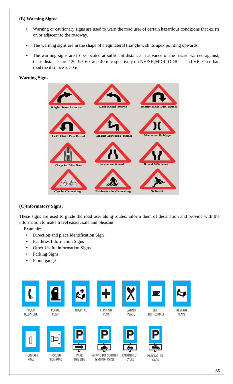
35
(B) Warning Signs:
• Warning or cautionary signs are used to warn the road user of certain hazardous conditions that exists on or adjacent to the roadway.
• The warning signs are in the shape of a equilateral triangle with its apex pointing upwards.
• The warning signs are to be located at sufficient distance in advance of the hazard warned against; these distances are 120, 90, 60, and 40 m respectively on NH/SH,MDR, ODR, and VR. On urban road the distance is 50 m
Warning Signs
(C)Informatory Signs:
These signs are used to guide the road user along routes, inform them of destination and provide with the information to make travel easier, safe and pleasant. Example:
• Direction and place identification Sign • Facilities Information Signs • Other Useful information Signs • Parking Signs • Flood gauge

36
Traffic Signals:
Definition: Traffic Signals are control devices which could alternately direct the traffic to stop and proceed at intersections using red and green traffic light signals automatically.
Advantages of Signals:
1. Signal is provided at intersection to manage the traffic flow. 2. Signals provide safety to vehicular traffic and pedestrian. They reduce and avoid the accidents. 3. Signals are easy to understand compare to traffic police management at intersection.
Disadvantages of Signals:
1. Fast moving vehicles may cause rear end collision at signalized intersection 2. Improper design of signal cycle length can cause fixed delay. 3. Duration off-peak hour unnecessary delay occurs at signalized intersection.
Purposes:
At Intersection where a large number of crossing and right turn traffic, there is possibility of collision and accident.
To provide orderly movement with safety and speed, signals are provided at intersection.
The crossing streams of traffic flow are separated by time segregation.
Types Of traffic Signals
Fixed Time Manually Operated Traffic actuated Pedestrian Special Traffic
Fixed Time Signals: are set to repeat regularly a cycle of red, amber and green lights. The timing demand to clear off the intersection with the help of detectors which are installed at the approaches. These are very costly.
Pedestrian Signals: are meant to give the right of way to pedestrians to cross a road. The vehicular traffic should be stopped by red or stop signal on the traffic signal of the road.
Traffic actuated Signals: are those in which the timings of the phase and cycle are changed according to traffic demand to clear off the intersection with the help of detectors which are installed at the approaches. They are very costly.

37
PARKING SYSTEM Types of Parking System
1. On -Street Parking 2. Off- Street Parking
1. On –street parking (Kerb parking):
The vehicles are parked on the kerb or on the side of street or road. Types of Kerb Parking:
Parallel Parking Angle parking
Parallel Parking:
Parallel parking is a method of parking a vehicle in line with other parked vehicles. Vehicles parked in parallel are in one line, parallel to the kerb, with the front bumper of each facing the back bumper of the next. Parallel parking allows a vehicle to park in a smaller space than would be true of forward parking. Parallel parking requires initially driving the vehicle slightly past the parking space followed by reversing into the space. Subsequent position adjustment may be required by the use of forward and reverse gears
Angle parking:
Angled parking is on-street parking in which the vehicle has it's front closest to the curb. Angled parking uses less linear curb length per parking space than traditional parallel parking so more spaces can be provided on the same block. This type of parking commonly occurs in parking lots, shopping centers and on very wide streets in some communities. In addition, angled parking acts as a traffic claiming device because a passing driver is aware that a parked vehicle could back into the roadway at any moment. Angle parking is more convenient for the motorists than the parallel parking. Angle parking is more convenient for the motorists than the parallel parking. Out of various angle parking, 45 0 angle parking is the best and most convenient.
Types of Angle parking: 30 0 angle parking 60 0 angle parking 45 0 angle parking 90 0 angle parking
2. Off –street parking When parking facility is provided at a separate place away from the kerb it is known as off-street
parking. Off-street parking is an important part of the transportation system. It is an efficient means of storing vehicles while they aren’t in use, and it causes little disruption to
the neighboring roadways. Additionally, since parking is the terminal or destination for a trip, the availability of off-street
parking can affect the attractiveness of destinations as well as transportation modes. Off-street parking facilities range from:
Car garage in the home Multi-story garages
Off-street parking becomes a necessity wherever the need for vehicle parking exceeds the capacity of on-street parking.
Types of off street parking: Surface parking lots Multi floor parking garages
A parking lot also known as car lot, is a cleared area that is intended for parking vehicles. Usually, the
term refers to a dedicated area that has been provided with a durable or semi-durable surface. In most countries where cars are the dominant mode of transportation; parking lots are a feature of every city and suburban area. Shopping Malls, sports stadiums, mega churches and similar venues often feature parking lots of immense area.

38
CAUSES OF ACCIDENTS:
1. Drivers: Excessive speed and rash driving, violation of rules and regulayion, sleep or alcohol. 2. Pedestrians: Violating regulation, carelessness in using the carriageway meant for vehicular traffic. 3. Passengers: Alighting from or getting into moving vehicles. 4. Vehicle defects: Failure of breaks, streeting system, lighting system, and any other defects in the
vehicles. 5. Road conditions: slippery or skidding road surface, pot holes and other damaged condition of road
surface. 6. Road design: Defective geometric design like sight distance, improper curve, design overtaking sight
distance etc. 7. Weather: Unfavorable weather like mist, fog, snow, dust, heavy rainfall etc. 8. Animals: Stray animals on the road. 9. Other Causes: Incorrect signs or signals, badly located advertisement board, ribbon development etc.

39
UNIT –III
ENVIRONMENT AND NATURAL RESOURCE
MANAGEMENT
WATER SUPPLY
1. INTRODUCTION
1.1 Importance and necessity of water supply schemes Water supply scheme involves:
(a) Collection (b) Conveyance (c) Treatment (d) Distribution of water
For every living being water, air, food, shelter etc are the primary needs of which the water has the greatest importance. It is truly said that the” water is best of all things”. Everywhere water is required for various purposes such as:
a) For drinking and cooking b) For bathing and washing c) Washing of clothes and utensils d) For watering of lawns and gardens e) For heating and air conditioning systems f) For growing of crops g) Fire fighting h) Steam power and various industrial processes i) Construction works j) Washing of vehicles k) Street washing l) Recreation in swimming pools fountains and cascades etc.
Without food human can survive for a number of days, but water is such an essential element without it he cannot. In the ancient times humans required water for drinking, bating, cooking etc. but with the advancement of civilization the utility of water enormously increased and now such a stage has come that without well organized public water supply scheme, it is impossible to run the present civic life and develop the towns.
In ancient times the water was collected from surface sources like rivers, lakes and ponds.etc. The original small water source become insufficient and large water sources become inevitable. The large water source may be far away from the township and the water may not be safe for dinking. The role of water supply scheme, i.e. collection, conveyance treatment and distribution of water comes in handy here. For every town or a city, an administrative body, either the municipality or corporation has been established to look after the public health and to supply potable water to consumers after proper treatment.
2) SOURCES Following are the sources of water:
1) Surface sources: a) Rivers, streams b) Lakes c) Ponds d) Impounded reservoirs.
2) Underground sources(sub-surface): a) Springs b) Wells

40
1) Artesian well 2) Dug/draw well 3) Tube well
c) Infiltration galleries.
SURFACE SOURCES: Natural Ponds and Lakes In mountains at some places natural basins are formed with impervious bed by springs and streams are known as “lakes”. The quality of water in the natural ponds and lakes depends upon the basin’s capacity, catchment area, annual rainfall, porosity of ground etc. But lakes and ponds situated at higher altitudes contain almost pure water which can be used without any treatment. But ponds formed due to construction of houses, road, and railways contains large amount of impurities and therefore cannot be used for water supply purposes. Streams and Rivers Rivers and streams are the main source of surface source of water. In summer the quality of river water is better than monsoon because in rainy season the run-off water also carries with clay, sand, silt etc which make the water turbid. So river and stream water require special treatments. Some rivers are snow fed and perennial and have water throughout the year and therefore they do not require any arrangements to hold the water. But some rivers dry up wholly or partially in summer. So they require special arrangements to meet the water demand during hot weather. Mostly all the cities are situated near the rivers discharge their used water of sewage in the rivers, therefore much care should be taken while drawing water from the river. Impounding Reservoirs: In some rivers the flow becomes very small and cannot meet the requirements of hot weather. In such cases, the water can be stored by constructing a bund, a weir or a dam across the river at such places where minimum area of land is submerged in the water and max. Quantity of water to be stored. In lakes and reservoirs, suspended impurities settle down in the bottom, but in their beds algae, weeds, vegetable and organic growth takes place which produce bad smell, taste and colour in water. Therefore this water should be used after purification. When water is stored for long time in reservoirs it should be aerated. SUBSURFACE SOURCES:
Infiltration Galleries
Infiltration Wells: In order to obtain large quantity of water, the infiltration wells are sunk in series in the blanks of river. The wells are closed at top and open at bottom. They are constructed by brick masonry with open joints as shown in fig.
Infiltration Well Jack Well

41
For the purpose of inspection of well, the manholes are provided in the top cover. The water filtrates through the bottom of such wells and as it has to pass through sand bed, it gets purified to some extent. The infiltration well in turn is connected by porous. pipes to collecting sump called jack well and there water is pumped to purification plant for treatment Springs: Sometimes ground water reappears at the ground surface in the form of springs. Springs generally supply small springs. Springs generally supply small quantity of water and hence suitable for the hill towns. Some springs discharge hot water due to presence of sulphur and useful only for the curve of certain skin disease patients.
Types of springs: 1. Gravity Springs: When the surface of the earth drops sharply the water bearing stratum is exposed to atmosphere and gravity springs are formed as shown in fig. 2. Surface Spring: This is formed when an impervious stratum which is supporting the ground water reservoir becomes out crops as shown in fig.
Surface Spring
3. Artesian Spring: When the ground water rises through a fissure in the upper impervious stratum as shown in fig.
Artesian spring
When the water-bearing stratum has too much hydraulic gradient and is closed between two imperious stratums, the formation of artesian spring from deep seated spring.
Artesian spring

42
Wells: A well is defined as an artificial hole or pit made in the ground for the purpose of tapping water. In India 75 to 85% of Indian population has to depend on wells for its water supply. The three factors which form the basis of theory of wells are 1. Geological conditions of the earth’s surface 2. Porosity of various layers 3. Quantity of water, which is absorbed and stored in different layers. The following are different types of wells 1. Shallow wells 2. Deep wells 3. Tube wells 4. Artesian wells (a) Shallow Wells: Shallow wells are constructed in the uppermost layer of the earth’s surface. The diameter of well varies from 2 to 6 m and a maximum depth of 7m. Shallow wells may be lined or unlined from inside. Fig. shows a shallow well with lining (steining). These wells are also called draw wells or gravity wells or open wells or drag wells or percolation wells.
Shallow Well
Quantity of water available from shallow wells is limited as their source of supply is uppermost layer of earth only and sometimes may even dry up in summer. Hence they are not suitable for public water supply schemes. The quantity of water obtained from shallow wells is better than the river water but requires purification. The shallow wells should be constructed away from septic tanks, soak pits etc because of the contamination of effluent. The shallow wells are used as the source of water supply for small villages, undeveloped municipal towns, isolated buildings etc because of limited supply and bad quality of water. (b) Deep Wells : The Deep wells obtain their quota of water from an aquifer below the impervious layer as shown in fig No. The theory of deep well is based on the travel of water from the outcrop to the site of deep well. The outcrop is the place where aquifer is exposed to the atmosphere. The rain water entered at outcrop and gets thoroughly purified when it reaches to the site of deep well. But it dissolves certain salts and therefore become hard. In such cases, some treatment would be necessary to remove the hardness of water.
Deep Well
The depth of deep well should be decided in such a way that the location of out crop is not very near to the site of well. The water available at a pressure greater atmospheric pressure, therefore deep wells are also referred to as a pressure wells.
3) DRINKING WATER REQUIRMENTS Absolutely pure water is never found in nature. Absolutely pure water is that water which only contains two parts of Hydrogen and one part of Oxygen by volume and nothing else. But the water found in nature contains number of impurities in varying amounts. While falling in the form of rains the water absorbs number of gases, dust and organic and inorganic impurities. This water when moves on ground further

43
carries the silts and other impurities. Therefore the runoff water has large no of impurities. These impurities make the water unsuitable for the drinking. Therefore such impurities must be removed from the water as well as while removing such impurities the essential elements and bacteria’s that naturally present in water and mostly useful for the human health must not be removed.
Therefore the drinking water has the following requirements
a) It should be free from the bacteria’s that causes the diseases.
b) It should be colourless
c) It should be odourless
d) It should be tasty and cool
e) It should be free from the silts
f) It should be free from any objectionable matter
g) It should have dissolved oxygen and free carbonic acid so that it may remain fresh
h) It should not corrode pipes
The water supplied to the community should be strictly according to the standards laid down from time to time.
4) WATER DEMAND 4.1 Types of Demands:
While designing the water supply schemes of the town, it is also necessary to determine the total years demand. Following are the various types of water demand of a city or town:
(i) Domestic water demand.
(ii) Commercial and Industrial demand.
(iii) Fire-demand.
(iv) Demand for public uses.
(v) Compensate losses demand.
4.2 Domestic Water Demand It includes the quantity of water required in the houses for drinking, bathing, cooking, washing etc. The
quantity of water required for domestic use mainly depends on the habits, social status, Climatic conditions and customs of the people. In India on an average, the domestic consumption of water under normal condition is about135 litres/day/capita as per IS: 1172-1171. In developed countries this figure may be as high as 350 litres/day/capita. The increase in water consumption in developed countries is mainly due to use of air coolers, air conditioners, maintenance of lawns, automatic household appliances such as home laundries, dishwashers etc.
Domestic Water Demand: The total consumption in this demand, generally amounts to 55 to 60% of the total water consumption the break up of 135 litres/day/capita may be taken as follows: .
Table 4.1 Average Domestic Water Consumption in an Indian City.
Heads Use Consumption in litres /day/ person
(a) Drinking 5
(h) Cooking 5
(c) Bathing 55
(d) Washing of clothes 20
(e) Washing of utensils 10
(j) Washing and cleaning of houses and residences
10
(g) Flushing of Latrines etc. 30
Total 135

44
4.2 Demands For Public Use Quantity of water required for public utility purposes such as for washing and sprinkling or roads
cleaning of sewers, watering of public parks, gardens, public fountains etc, comes under public demand. To meet the water demand for public use, provision of 5% of the total consumption is made while designing the water works for a city.
The requirements of water for public purposes shall be taken as given in Table 5.2. Table 4.2. Water Requirements For Public Purpose.
S. No. Purpose Water Requirement
1. Public parks 1.4 litres/day/capita
2. Street washing 1.0 litres/day/capita
3. Sewer cleaning litres/day/capita 4.3 Per Capita Demand In community water is used for various purposes as described above. For the purpose of estimation of
total requirements of water, the demand is calculated on an average basic, which is expressed as so many litres/capita/day.
If Q is the total quantity of water required by a town per year in litres, and the population of the town is P, the per capita demand will be.
Per capital demand = Q litres / day. P x 365 QUANTITY OF WATER The per capita demand of the town depends on various factors and will be according to the living
standard of the public and the number and type of the commerical places in the town etc. For an average Indian town, the requirement of water in various uses is as under:
(i) Domestic use 135 litres/capita/day (iij Industrial 40 litres/capita/day (iii) Public use 25 litres/capita/day (iv) Fire demand 15 litres/capita/day (v) Losses, wastage and thefts 55 litres/capita/day Total quantity of water required by the town per day shall be 270 multiplied with the total population
of litres/day. 5) IMPURITIES IN WATER AND THEIR EFFECT Impurities in water can be listed as follows: a) Suspended impurities b) Colloidal Impurities c) Dissolved impurities (a) Suspended Impurities: These impurities are the suspension of solid particles that are large enough to be removed by filtration or surface and heavier ones settle down. The suspended particles which have same specific gravity as that of water are mixed in the water. Suspended impurities include clay, algae, fungi, organic and inorganic matter and mineral matter etc. These all impurities are macroscopic and cause turbidity in water. The concentration of suspended matter in water is measured by its turbidity. Examples: sand clay and other inorganic soils, algae, bacteria’s. (b) Colloidal Impurities: It is very finely divided dispersion of particles in water. These particles are so small that these particles cannot be removed by ordinary filters and are not visible to the naked eye. As a matter of fact all the colloidal impurities are electrically charged and remain in continuous motion. The electric charge is due to presence of absorbed ions on the surface of the solid. Acid or neutral materials such as silica, glass and most organic particles acquire negative charge in neutral water, where as basic materials such as metallic oxides AL2O3 and. Fe2O3 are positively charged. These electric charges on the surfaces of particles are large enough in comparison with their mass to cause the particles to repel one another when they move within the sphere of action of each others charge. Due to this repelling action all colloidal particles remain in motion and do not settle. That is why there removal is very difficult. These

45
colloidal impurities are generally associated with organic matter containing bacteria’s and are the chief source of epidemics. Most of the colour of water is due to colloidal impurities their quantity is determined by the colour tests. The size of colloidal particles is in between (1=1 micron=0.001mm) to (1=1 milli micron =0.000001mm) or (10-3 mm to 10-6mm). Examples: Silica, clay, iron oxide Fe2O3 , aluminum AL2O3 , manganese oxide MnO2 ,Vegetable and organic waste. (c) Dissolved Impurities: Some impurities are dissolved in water when it moves over the rocks, soil etc. solids, liquids; gases are dissolved in natural waters. These dissolved impurities may contain organic compounds, inorganic salts and gases etc. The concentration of local dissolved solids is usually expressed in p.p.m and is obtained by weighing the residue after evaporation of the water sample from a filtered sample. Examples: calcium, magnesium, sodium, potassium, iron, salts, gases like hydrogen. Effects of the impurities IMPURITY CONSTITUENTS EFFECTS
Suspended Impurities
a) Bacteria b)Algae, Protozoa c)Silts
Some cause diseases Odour, Colour, Turbidity Murkiness or Turbidity
Dissolved Impurities
a)Salts 1)Calcium & Magnesium
Bicarbonate Alkalinity Alkalinity & Hardness Hardness Hardness Corrosion
Carbonate
Sulphate
Chloride
2)sodium
Bicarbonate Alkalinity, Softening effect Alkalinity, Softening effect Foaming in Boilers Dental Flurosis or mottled enamel Taste
Carbonate Sulphate Fluoride Chloride
b) Metals and Compounds Taste, red colour, corrosiveness, hardness Black or brown colour Cumulative poisoning Toxicity , poisoning Toxic effect on heart and nerves Toxic & illness Fatal Affect central nervous system Highly toxic to animals Discoloration of skin & eyes Blue baby conditions, infant poisoning, colour, acidity
Iron oxide Manganese Lead Arsenic Barium Cadmium Cyanide Boron Selenium Silver nitrates
( c ) Vegetable Dyes
( d ) gases Oxygen Corrosiveness to metals
Acidity, corrosiveness Odour, acidity, corrosiveness
Carbon Dioxide Hydrogen Sulphide
6) TREATMENT OF WATER (Purification of Water) GENERAL INTRODUCTION Water available in various sources contains various types of impurities and cannot be directly used by the public for various purposes, before removing the impurities. For potability water should be free from unpleasant tastes, odours and must have sparkling appearance. The water must be free from disease-spreading germs. The amount and type of treatment process will depend on the quality of raw water and the standards of quality of raw water and the standards of quality to be required after treatment as per the table no.

46
The surface sources generally contains large amount of impurities therefore they requires sedimentation, filtration and chlorination as treatment. If the water contains algae or other micro organisms, pre chlorination has to be done tastes and odours , dissolved gases like CO2, H2S are removed by aeration. During the flood season, the turbidity of the surface water may be high and flocculation may become necessary to remove turbidity. Ground water which is usually clear may require only disinfection and chemical treatment for the removal of pathogens, Iron removal, Softening etc. Sometimes ground water contains dissolved gases like hydrogen sulphide (H2S) carbon dioxide (CO2), which gives very bad odour and requires its removal by aeration.
PURIFICATION OF WATER Object: The water from sources may have some characteristics which are unsuitable for human consumption, industrial use, commercial use etc. the following are some of those characteristics: a) Turbidity b) It may contain colour c) It may contain acids, salts and gases which have corrosive action and may impart hardness of water. d) It may contain bacteria which may cause water borne diseases. Therefore the object of purification of water is to remove those impurities and make the water suitable for domestic, industrial, commercial uses. Underground water may be free from the above impurities but sometimes it may possess the property of hardness which should be removed. PRIMARY TREATMENT OF WATER (TREATMENT UNIT FLOW DIAGRAM) Water treatment includes many operations like Aeration, Flocculation, Sedimentation, Filtration, Softening, Chlorination and demineralization. Depending upon the quality of raw water and the quality of water desired. Several combinations of the above processes may be adopted as shown in the flow diagram above processes may be adopted as shown in the flow diagram
One complete water treatment plant requires the following process starting from the source of water up to the distribution zone in order of sequence SEQUENCE OF UNITS: 1) Intake point 2) Pump house 3) Plain sedimentation tank 4) Coagulation tank 5) Filtration unit 6) Chlorination unit 7) Water softening plant
8) Over-head reservoir

47
The following points should be kept in mind while giving layout of any treatment plant. 1. The W.T.P. should be located as near to the town so as to avoid the contamination. 2. All the units of plant should be located in order of sequence and flow from one unit to other by gravity. 3. All the units are arranged in such a way that minimum area is required so as to reduce the cost of construction. 4. Sufficient area should be reserved for the future expansion 5. Staff quarters and office should be provided near the treatment plants so that the operators can watch the plants easily. 6. The site of treatment plant should be very neat and give very good aesthetic appearance.

48
Functions of units:
1) Intake point: The function of this unit is to collect water in the intake well so that the water can be supplied throughout the year.
2) Pump House: The function of this unit is to draw the water from the intake well and to supply same to the treatment plat.
3) Plain Sedimentation Tank: The function of this unit is to remove the heavier suspended particles in water. In this tank the water is detained for some period or allowed to flow at very low velocity so that the heavier suspended particles are settle down at the bottom of the of sedimentation tank but some lighter particles still remain in suspension.
4) Coagulation Tank: the function of this unit is to remove the lighter suspended particles by the application of some coagulants. In this tank some recommended coagulants is mixed with water and the water is allowed to flow at very low velocity through the coagulation tank. The coagulants make the liter particles to gain the settle able size and ultimately settle down at the bottom of the tank but some finer colloidal particles still remain in the suspension.
Sedimentation with Coagulation 5) Filtration Unit: The function of this unit is to remove the finer colloidal particles and some
bacteria for filtering media of sand and gravel but some bacteria still remain in the water. 6) Chlorination unit: the function of this unit is to destroy the bacteria by application of chlorine. 7) Water Softening Tank: the function of this unit is to remove the hardness of water to make it fit
for commercial purpose. This unit is not always necessary. 8) Overhead Reservoir: The function of this unit is to store purified water after the treatment is
complete. The water from the reservoir is supplied to the consumers by gravity.
7) DISINFECTION OF WATER NECESSITY OF DISINFECTION: The processes of destroying harmful bacteria from water and to make it safe for drinking is known as disinfection. The substances used for disinfection used for disinfectants. The common disinfectants are lime, iodine and bromine, ozone, potassium permanganate, silver; chlorine etc. chlorine is the most important disinfectant which has a wonderful power for killing bacteria in short span of time with a minimum amount of expenditure. So this chemical is used in most developing countries.
The processes of destroying all the bacteria (either harmful or harmless) are known as sterilization. But in a water supply scheme, we require only the removal of harmful bacteria’s (i.e. pathogenic bacteria) which may cause water borne diseases like cholera, dysentery, typhoid etc. REQUIREMENTS OF GOOD DISINFECTANTS 1. They should destroy all the harmful pathogens and make it safe for use,. 2. They should not take more time in killing bacteria 3. They should be economical and easily available 4. They should not require high skill for their application 5. After treatment the water should not become toxic and objectionable to the user. 6. The concentration should be determined by simply and quickly. METHODS OF DISINFECTION:
a) Disinfection by boiling b) By ultra-violet rays c) By iodine and bromine d) By excess lime e) By ozone

49
f) By potassium permanganate g) By silver h) By chlorine
Disinfection by Boiling: When water is boiled to the boiling temperature ( 100oc ) the bacteria is completely removed. It should be boiled at least for 10-15 minutes. Boiling also removes some of the dissolved salts. It is the most effective method of disinfection. But this is not suitable for large scale. It is suitable for domestic purpose, i.e. to boil water before its use as drinking water. In case of an epidemic, the consumers should always boil water to check the water borne diseases.
Disinfection by ultraviolet rays: When mercury enclosed in a quarts bulb an electric current is passed through it, the ultra violet rays are emitted. These rays are found to be very powerful in killing all type of bacteria. In this method the water is allowed to flow under the bulb for several times. The depth of flow should not exceed 10-15 cm. this method does not impart any taste or colour to the water or there is no possibility of overdosing. It is costly processes and suitable for small water supply installations like factories, institutions, training camp, etc.
Disinfection by iodine and bromine: the iodine and bromine also have property of killing bacteria. Dose of iodine and bromine should be 8-10 ppm. These chemicals are available in the form of small pellets. The water is stored in a suitable container and required number of pellets are dropped in the water and left for 5 minutes. Water becomes safe for drinking. This method is suitable for small water supply installations like industries, military or survey camps.
Disinfection by excess lime: naturally lime is added to the water is to remove some salts but when excess lime is added to the water it is found to be act as a disinfectant. The excesses lime increases the pH value of water i.e. increases the alkalinity of water which is detrimental to bacteria because bacteria cannot resist the alkalinity of water. It is found that pH value 9-10 can remove bacteria to the extent of 99% but after treatment the residual lime should be removed by the method of re carbonation.
Disinfection by ozone: in atmosphere the molecules of oxygen contains two items (O2 ) but it changes to three when electric current of high voltage is passed through the stream of air in chamber. This triatomic oxygen is known as ozone (O 3 ).the ozone easily breaks into oxygen ( O2 ) and nascent atom ( O ). This third atom is very powerful in killing bacteria. The dose of ozone varies from2-5 ppm and contact period varies from 5-10 mins. If after treatment some residual ozone is present in water, it is automatically removed. Since ozone is unstable in nature, there is no possibility any danger to the consumers. It is costly method.
Disinfection by potassium permanganate: potassium permanganate is a powerful oxidizing agent. It oxidizes the organic matter present in water and hence the bacteria get killed. this mostly used for disinfecting water of wells in village, swimming pools, ponds etc. not suitable for large scale. Dose of chemical is about2-3 ppm and contact period is 2-3 hrs.
Disinfection by chlorine: Chlorine has got the wonderful power of destroying bacteria. It is best among all the other disinfectants used for the disinfection of water. It kills bacteria very fast and its effect effect lasts for such a long time that it even acts in the distribution systems. It is cheap and reliable. If some residual chlorine exists in water it does not cause any harm to the consumers.
8) STANDARDS OF PURIFIED WATER The physical, chemical, bacteriological standards for water quality as suggested by the following agencies: 1) Indian Council of Medical Research (I.C.M.R) committee 2) World Health Organization (W.H.O) 3) United States Public Health Society (U.S.P.H.S) 4) American Water Works Association (A.W.W.A) The manual on water supply and treatment prepared by the central public health and environmental engineering Organization, under the Ministry of Urban Development (MUD) India lays down the following standards of water.

50
S.N CHARECTERISTICS ACCEPTIBLE CAUSE OF REJECTION
1 Turbidity ( J.T.U scale) 2.5 10
2 Colour (platinum cobalt scale) 5.0 2.5
3 Taste and Odour unobjectionable Unobjectionable
4 Total Dissolved Solids(mg/l) 500 1500
5 Hardness ( as CaCO3) (mg/l) 200 600
6 Chlorides ( as Cl) (mg/l) 200 1000
7 Fluorides ( as F) (mg/l) 1.0 1.5
8 Sulphates ( as SO4) (mg/l) 200 400
9 Nitrates ( as NO3) (mg/l) 45 45
10 Calcium ( as Ca) (mg/l) 75 200
11 Magnesium ( as Mg) (mg/l) 30 150
12 Iron ( as Fe) (mg/l) 0.1 1.0
13 Manganese ( as Mn) (mg/l) 0.05 0.5
14 Copper (as Cu) (mg/l) 0.05 1.5
15 Zinc (as Zn) (mg/l) 5.0 15.0
Toxic materials
16 Arsenic ( as As) (mg/l) 0.05 0.05
17 Cadmium (as Cd) (mg/l) 0.01 0.01
18 Chromium (as Hexavalent Cr) (mg/l) 0.05 0.05
19 Cynides ( as Cn) (mg/l) 0.05 0.05
20 Lead (as Pb) (mg/l) 0.1 0.01
21 Mercury (total Hg) (mg/l) 0.001 0.001
Radio Activity
22 Gross Alpha Activity 3 pci/l 3 pci/l
23 Gross Beta Activity 30 pci/l 30 pci/l
24 Pci= pico curie
The figures indicated under acceptable column are the limits up to which the water is generally acceptable for consumers. Cause of rejection column shows the limit of tolerance if the supply contains the impurities exceeds the limit the water is not safe for drinking and must be rejected.
WASTE MANAGEMENT (Collection & disposal methods of liquid, solid and gaseous wastes) SANITARY ENGINEERING It is the branch of public health engineering which deals with the preservation and maintenance of health of the individual and the community, by preventing communicable diseases. It consists of scientific and methodical collection, conveyance, treatment and disposal of waste matter so that public health can be protected from the offensive and injurious substances. Sanitation is the prevention of sporadic outbreak of disease, and can be achieved by either controlling or eliminating such environmental factors that contributes into the some form or the other to the transmission of diseases. If the waste water created and given out by the human and animal life, and also by industries etc, is allowed to accumulate, it will get decompose and will contaminate or pollute air, water and food. Hence sanitary disposal of waste, either in solid form or in liquid form, is most essential. The sanitary sewage includes excreta (i.e. waste matter eliminated from the boy), domestic sewage (i.e. used water form the home community which includes toilet, bath, laundry, and Lavatory and kitchen-sink wastes) and industrial waste. The improper disposal of human excreta and sewage is the major factor threatening the health and comfort of individuals where satisfactory sewage system is not available.

51
IMPORTANT TERMS AND DEFINATIONS: 1) Refuse: is a general term used to indicate what is rejected or let out as worthless. It may be liquid, semisolid or solid form and may be divided into six catagories: a) garbage b) rubbish c) sullage d) sewage e) subsoil water f) storm water. 2) Garbage: Dry refuse such as papers, decayed fruits, vegetables, grass and leaves, and sweeping from streets, markets and other public places. Thus garbage contains large amount of organic and putrefying matter. 3) sullage: sullage is a term used to indicate waste water from bathrooms kitchens, washing places and wash basins etc. It does not create any bad smell because the organic matter in it is either absent or in very negligible amount. 5) Sewage: sewage indicates the liquid waste from community. It includes sullage , discharge from latrines, urinals, stables, industrial waste and also ground surface and storm water. It is extremely putrescible: its decomposition produces large quantities of malodorous gases and it may contain numerous pathogenic or disease producing bacteria. 6) Sub-soil water: it is the ground water that finds its entry into sewers through leaks. 7) Storm water: it indicates the rain water of the locality 8) Sanitary sewage: sanitary sewage or the domestic sewage indicates sewage mainly derived from the residential building and industrial establishments. It is extremely foul in nature. Sanitary sewage may be classified as a) domestic sewage and b) industrial sewage. 9) Domestic sewage: it is the sewage obtained from the lavatory basins, urinal and water closets of residential buildings office buildings, theaters and other institutions. Since it contains human excreta and urine, it is extremely foul in nature. 10) Industrial sewage: It s wastewater obtained from the industrial and commercial establishments. Is may contain objectionable organic compounds that may not be amenable to conventional treatment processes. 11) Night soil: It is a term used to indicate the human excreta. 12) Sewer: it is an underground conduit or drain through which sewage is carried to a point of discharge or disposal. Sources of Wastes:
• Solid waste- vegetable waste, kitchen waste, household waste etc. • E-waste- discarded electronic devices like computer, TV, music systems etc. • Liquid waste- water used for different industries e.g. tanneries, distilleries, thermal power plants • Gaseous waste: • Plastic waste- plastic bags, bottles, bucket etc. • Metal waste- unused metal sheet, metal scraps etc. • Nuclear waste- unused materials from nuclear power plants
For the disposal of waste products of a town two works are required: 1) Collection works 2) Disposal works The disposal works mainly consists of treatment works which are essential to neither treat the waste water and dispose it off on such a way that it may not cause any harm to the health of public nor pollute the nearby water sources and environment. The collection works are the works which are done to collect the waste products. In olden days it was done by the conservancy method, but in modern cities it is done by water carriage method. The water carriage system has so many systems as separate, combined or partially separate in which the sewage or storm water can be collected. METHODS OF COLLECTION The sanitation of a town or city is done by two methods which are: 1) Conservancy system 2) Water carriage System. CONSERVANCY SYSTEM This is an old system in which various types of wastes, such as night soil, garbage etc. are collected separately in vessels or deposited in pools or pits and then removed periodically at least once in 24hrs. On account of this method of handling independently the different type of refuse from place the term

52
conservancy system has been derived. The system is also known as the dry system. The following are the methods of collection of various types of waste in the system. 1) Night soil: night soils or human excreta in latrines, privies or cesspools etc . is collected separately in pans or pails and carried on heads of sweepers to a central place from where it is transported in bullock carts or motor vans to a place away from the town for final disposal. Normally it is buried into ground, in trenches, to give excellent manure in one or two years.
2) Garbage: garbage is collected separately, in dust bins and conveyed on head, carts or motor vans once or twice a day. It may consist of waste matter of both non combustible as well as combustible type the two are therefore sorted out. Garbage disposal method includes the open ump, hog fiddling, and incineration, dumping into sanitary field, fermentation or biological digestion.
Incineration, if properly controlled, is satisfactory for burning combustible diffuse. 3) Refuse: sullage and storm water. Sullage and storm water are collected and conveyed separately
in closed or open gutters. The liquid and semi liquid mass of filth which frequently overflow the receptacles in privies is swept away by the sweepers to drain from the privies, which carry it to drains carrying sullage and storm water , along the public lanes or streets. In India, the conservancy system is still on vogue in all the villages and small towns. Only a few cities have the water carriage systems. Disadvantages of conservancy system:
1) Hygiene and sanitary aspect: the conservancy system is highly unhygienic and cause insanitary conditions since the excreta start decomposing within few hrs of its production. Even if it is assumed that cleaning will take place twice in a day, the excreta remaining in the privies will emit bad smell and will give rise to fly nuscence.
2) Transportation aspect: transportation of night soil takes place in open carts through streets and other crowded localities this is highly undesirable.
3) Labor aspect: the working of the system depends entirely on the mercy of labors (sweepers). If they go on strike even for one day for any reason what so ever, the privies can not be used because of foul smell. Te whole locality will smell very badly.
4) Building design aspect: The lavatories or privies are to be located outside the house and slightly away from the main building the compact design is therefore is not possible.
5) Conditions of drains: insanitation may be there due to carriage of sullage through open drains laid in the streets.
6) Human aspects: in the present day world, when man has progressed much, it is highly humiliating to ask human beings to transport night soil in pails on their heads.
7) Risk of epidemic: due to improper or careless disposal of night soil, there are more chances of outbreak of epidemic.
8) Pollution problems’: Liquid waste from lavatories etc., during their washing may soak in the ground, thus contaminating the soil. If the ground water is a t a shallow depth, it may also be polluted due to percolation of waste water.
9) Cost consideration: though t system is quit cheap in the beginning its maintenance and establishment cost are very high.
10) Disposal land requirements: the system requires considerable land for the disposal of sewage. WATER CARRIAGE SYSTEM In this system, the collection, conveyance and disposal of various types of waste are carried out with the help of water. Thus water is used as medium to convey the waste from its point of production to the pint of its treatment or a final disposal. Sufficient quantity of water is required to be mix with the waste so that dilution ratio is so great that the mixture may flow just like water. In this system, specially designed latrines called water closet (w.c) are used which are flushed with 5-10 liters of water after its used by every person the human excreta is thus flushed away and lead to suitable design and maintain sewer. The waste from kitchens, baths, wash basins etc. re also laid to the sewers the sewers are the underground closed pipes which are laid on suitable longitudinal gradient slow that flow takes under gravity and proper flow velocity is maintained to keep the sewer clean. The sewers laid the sewerage so collected to suitable site where it is treated suitably and then is disposed off by irrigation or by dilution. It should be noted that the garbage is collected separately and conveyed in same manner as in case if conservancy system. If garbage is permitted in the sewers, they may be clogged. This system requires large initial cost of installation and it requires large quantity of water also to create efficient flow conditions. If the financial conditions of people are poor, it may be difficult to adopt

53
this system. However this is the most efficient and hygienic system of sewerage disposal, and may be adopted in stages if sufficient funds are not available in the beginning. ADVANTAGES OF WATER CARRIGE SYSTEM This is the most modern system of drainage with the following advantages.
1) Huygens and sanitary aspect: the system is very hygienic since the night soil and other waste water is conveyed through closed conduits which are not directly exposed to the atmosphere. There is no bad smell because of continuous flow.
2) Epidemic aspect: there are no chances of outbreak of epidemic because flies and other insects do not have direct access to the sewage.
3) Pollution aspect: the liquid waste etc. is directly conveyed through the sewers, and therefore there are no changes of the waste Water being soaked in the ground thus contaminating the soil. The waste water dies not percolate down to join the ground water. There are no chances of pollution of water of well in individual houses if any.
4) Compactness in design: since the latrines are flushed after every use, excreta do not remain and there are no foul smells. The latrines can therefore be attached to the bedrooms and living. This permits a compact design. The lavatories can be accommodated in any part of the house.
5) Labour aspect: the labour required for the operation and maintenance is extremely small. In fact, the functioning of the system is practically automatic; except for the operation of certain pumps etc. there is no labour problem. In the individual houses, the latrines/lavatories can be conveniently cleaned by occupants themselves.
6) Treatment aspect: the system permits the use of modern methods of treatment of the sewage collected through the sewers. The treated waste water and sewage can be safely disposed of without any risk.
7) Land disposal requirements: because of treatment facilities the land required for the disposal of the treated waste water is very much smaller than that required for the conservancy system.
8) Cost consideration: though the initial cost of installation of the system are very high, the running costs are very small manual labour is very much reduced.
Management of Solid Waste For waste management we stress on ‘three R’s’-Reduce, reuse and recycle before destruction and safe storage of wastes.
(i) Reduction in use of raw materials: Reduction in the use of raw materials correspondingly decreases the production of waste. Reduced demand for any metallic product decreases its mining, hence less production of waste.
(ii) Reuse of waste materials: The refillable containers and plastic bags which are discarded after use should be reused. In Villages casseroles and silos are made from waste paper and rubber rings from discarded cycle tubes. Such practices reduce waste generation
(iii) Recycling of materials: Recycling is the reprocessing of discarded materials into new useful products.
Formation of some old type products e.g., old aluminum cans and glass bottles are melted and recast into new cans and bottles.
Formation of new products: Preparation of cellulose insulation from paper, preparation of fuel pellets from kitchen waste. Preparation of automobiles and construction materials from steel cans.
The process of reducing, reusing and recycling saves money, energy, raw materials, land space and also reduces pollution. Recycling of paper will reduce cutting of trees for making fresh paper. Reuse of metals will reduce mining and melting of ores for recovery of metals from ores and prevent pollution.
(iv) Waste disposal: For discarding wastes the following disposal methods can be adopted:
Sanitary landfill: In a sanitary landfill, garbage is spread out in thin layers, compacted and covered with clay or plastic foam. In the modern landfills the bottom is covered with an impermeable liner, usually

54
several layers of clay, thick plastic and sand. The liner protects the ground water from being contaminated due to percolation of leach ate. Leach ate from bottom is pumped and sent for treatment. When landfill is full it is covered with clay, sand, gravel and top soil to prevent seepage of water. Several wells are drilled near the landfill site to monitor if any leakage is contaminating ground water. Methane produced by anaerobic decomposition is collected and burnt to produce electricity or heat. Composting: Due to shortage of space for landfill in bigger cities, the biodegradable yard waste (kept separate from the municipal waste) is allowed to degrade or decompose in an oxygen rich medium. A good quality nutrient rich and environmental friendly manure is formed which improves the soil conditions and fertility. Wormy technology, using earthworms can further help in converting solid organic waste into good quality compost. Incineration: Solid wastes can be brunt in large amounts at high temperature (around 1800°C) in incinerator. Incinerator is a high temperature furnace used for burning solid wastes. Earlier incinerators used to be made of simple brick lining, but the modern ones are rotary. Kiln incinerators having a long inclined passage through which the waste is constantly moved. There is about 75% reduction in waste mass and 90% reduction in volume. The incinerators in which the waste to be burnt is not segregated are known as mass burn incinerators. There are special incinerators where potentially harmful or hazardous.
Water Resources Engineering Introduction to Hydraulic structures of storage A hydraulic structure is a structure submerged or partially submerged in any body of water, which disrupts the natural flow of water. They can be used to divert, disrupt or completely stop the flow. An example of a hydraulic structure would be a dam, which slows the normal flow rate of river in order to power turbines. A hydraulic structure can be built in rivers, a sea, or any body of water where there is a need for a change in the natural flow of water 1)Dam is a solid barrier constructed at a suitable location across a river valley
Storage of water is utilized for following objectives: to store flowing water. Drought and flood Water for domestic consumption Irrigation Hydropower Other additional utilization is to develop For navigational facilities Control fisheries
BASED ON PURPOSE 1. STORAGE DAM OR IMPOUNDING DAM 2. DETENTION DAM 3. DIVERSION DAM 4. COFFER DAM 5. DEBRIS DAM 1. STORAGE DAM OR IMPOUNDING DAM:- It is constructed to create a reservoir to store water during periods when there is huge flow in the river (in excess of demand) for utilisation later during periods of low flow (demand exceeds flow in the river). Water stored in the reservoir is used for irrigation, power generation, water supply etc. By suitable operation, it can also serve as a detention dam.
2. DETENTION DAM: - It is primarily constructed to temporarily detain all or part of the flood water in a river and to gradually release the stored water later at controlled rates so that the entire region on the downstream side of the dam is protected from possible damage due to floods. It may also be used as a storage dam.
3. DIVERSION DAM: - It is constructed to divert part of or all the water from a river into a conduit or a channel. For diverting water from a river into an irrigation canal, mostly a diversion weir is constructed across the river.

55
4. COFFER DAM: - It is a temporary dam constructed to exclude water from a specific area. It is constructed on the u/s side of the site where a dam is to be constructed so that the site is dry. In this case, it behaves like a diversion dam.
5. DEBRIS DAM:-It is constructed to catch and retain debris flowing in a river.
Figure: Dam Construction
BASED ON HYDRAULIC DESIGN
1. OVERFLOW DAM OR OVERFALL DAM
It is constructed with a crest to permit overflow of surplus water that cannot be retained in the reservoir. Generally dams are not designed as overflow dams for its entire length. Diversion weirs of small height may be designed to permit overflow over its entire length.
2. NON-OVERFLOW DAM
It is constructed such that water is not allowed to overflow over its crest.
In most cases, dams are so designed that part of its length is designed as an overflow dam (this part is called the spillway) while the rest of its length is designed as a non-overflow dam. In some cases, these two sections are not combined.
BASED ON MATERIAL OF CONSTRUCTION
1. RIGID DAM
It is constructed with rigid material such as stone, masonry, concrete, steel, or timber. Steel dams (steel plates supported on inclined struts) and timber dams (wooden planks supported on a wooden framework) are constructed only for small heights (rarely).
2. NON-RIGID DAM (EMBANKMENT DAMS)
It is constructed with non-rigid material such as earth, tailings, rock fill etc.
Earthen dam – gravel, sand, silt, clay etc
Tailings dam – waste or refuse obtained from mines
Rock fill dam – rock material supporting a water tight material on the u/s face
Rock fill composite dam – Rockfill on the d/s side and earth fill on the u/s side
Earthen dams are provided with a stone masonry or concrete overflow (spillway) section. Such dams are called composite dams.
In some cases, part of the length of the dam is constructed as earth dam and the rest (excluding the spillway) as a masonry dam. Such dams are called masonry cum earthen dams.
BASED ON STRUCTURAL BEHAVIOUR
1. GRAVITY DAM 2. ARCH DAM 3. BUTTRESS DAM 4. EMBANKMENT DAM

56
GRAVITY DAM It is a masonry or concrete dam which resists the forces acting on it by its own weight. Its c/s is approximately triangular in shape. Straight gravity dam – A gravity dam that is straight in plan. Curved gravity plan – A gravity dam that is curved in plan. Curved gravity dam (Arch gravity dam) – It resists the forces acting on it by combined gravity action (its own weight) and arch action. Solid gravity dam – Its body consists of a solid mass of masonry or concrete Hollow gravity dam – It has hollow spaces within its body. Most gravity dams are straight solid gravity dams Concrete Gravity Dams
Weight holds dam in place
Lots of concrete (expensive)
These dams are heavy and massive wall-like structures of concrete in which the whole weight acts vertically downwards
As the entire load is transmitted on the small area of foundation, such dams are constructed where rocks are competent and stable.
o Bhakra Dam is the highest Concrete Gravity dam in Asia and the second highest in the world. o Bhakra Dam is across river Sutlej in Himachal Pradesh o The construction of this project was started in the year 1948 and was completed in 1963 . o It is 740 ft. high above the deepest foundation as straight concrete dam being more than three times
the height of Qutab Minar. o Length at top 518.16m (1700 feet); width at base 190.5m (625 feet), and at the top is 9.14m (30
feet) o Bhakra Dam is the highest Concrete Gravity dam in Asia and Second Highest in the world.
2. ARCH DAM
It is a curved masonry or concrete dam, convex upstream, which resists the forces acting on it by arch action.
The only arch dam in India – Idukki dam (double curvature in plan) – concrete arch dam
Arch Dams
o Arch shape gives strength o Less material (cheaper) o Narrow sites o Need strong abutments
3. BUTTRESS DAM
It consists of water retaining sloping membrane or deck on the u/s which is supported by a series of buttresses. These buttresses are in the form of equally spaced triangular masonry or reinforced concrete walls or counterforts. The sloping membrane is usually a reinforced concrete slab. In some cases, the u/s slab is replaced by multiple arches supported on buttresses (multiple arch buttress dam) or by flaring the u/s
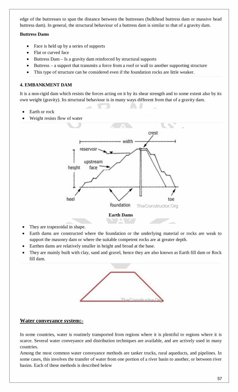
57
edge of the buttresses to span the distance between the buttresses (bulkhead buttress dam or massive head buttress dam). In general, the structural behaviour of a buttress dam is similar to that of a gravity dam.
Buttress Dams
Face is held up by a series of supports Flat or curved face Buttress Dam – Is a gravity dam reinforced by structural supports Buttress – a support that transmits a force from a roof or wall to another supporting structure This type of structure can be considered even if the foundation rocks are little weaker.
4. EMBANKMENT DAM
It is a non-rigid dam which resists the forces acting on it by its shear strength and to some extent also by its own weight (gravity). Its structural behaviour is in many ways different from that of a gravity dam.
Earth or rock Weight resists flow of water
Earth Dams
They are trapezoidal in shape. Earth dams are constructed where the foundation or the underlying material or rocks are weak to
support the masonry dam or where the suitable competent rocks are at greater depth. Earthen dams are relatively smaller in height and broad at the base. They are mainly built with clay, sand and gravel, hence they are also known as Earth fill dam or Rock
fill dam.
Water conveyance system:- In some countries, water is routinely transported from regions where it is plentiful to regions where it is scarce. Several water conveyance and distribution techniques are available, and are actively used in many countries. Among the most common water conveyance methods are tanker trucks, rural aqueducts, and pipelines. In some cases, this involves the transfer of water from one portion of a river basin to another, or between river basins. Each of these methods is described below

58
1)Tanker Trucks: Tanker trucks are fitted with a cistern or storage tank to transport and distribute water from a point of supply to the point of use, particularly to suburban and rural areas not served by a piped supply. If water is not supplied from a central treatment facility, it is usually extracted from the closest natural source (rivers, canals, reservoirs, or groundwater sources) and transported by the trucks to the point of use. Water thus transported may be pumped into a storage cistern, dispensed directly into household or other containers, or discharged into a small-scale treatment facility for centralized distribution. The tanks on the trucks are usually manufactured locally, and some trucks are equipped to carry portable pumps to extract the water from its source. 2) Pipelines: Water may conveyed through pipelines by gravity flow or by pumping. The latter system will be significantly more expensive to construct, operate and maintain than similar gravity-flow systems. Large-diameter pipelines can be used to convey water over large distances, while smaller-diameter pipelines can be used to provide bulk or individual supplies at the point of use. 3) Aqueducts: Aqueducts are canals used to bring water from a river or reservoir to a water distribution center. The main factors to be considered in the design of an aqueduct are the demand to be met, the source of the water, the topography in the area in which the aqueduct is to be built, the size and nature of the storage facilities, and the size and location of the distribution network. Aqueducts are best suited to meeting large-scale demands in areas with a fairly flat or gently sloping landscape suitable for conveying water to the point of use by gravity. 4) Open canals: An open canal, channel, or ditch, is an open waterway whose purpose is to carry water from one place to another. Channels and canals refer to main waterways supplying water to one or more farms. Field ditches have smaller dimensions and convey water from the farm entrance to the irrigated fields. According to the shape of their cross-section, canals are called rectangular (a), triangular (b), trapezoidal (c), circular (d), parabolic (e), and irregular or natural (f) A trapezoidal canal cross-section
A side slope of 1:2 (one to two) The freeboard of the canal is the height of the bank above the highest water level anticipated. It is required to guard against overtopping by waves or unexpected rises in the water level. The side slope of the canal is expressed as ratio, namely the vertical distance or height to the horizontal distance or width. For example, if the side slope of the canal has a ratio of 1:2 (one to two), this means that the horizontal distance (w) is two times the vertical distance (h)

59
The bottom slope of the canal does not appear on the drawing of the cross-section but on the longitudinal section (see Fig. 76). It is commonly expressed in percent or per mil.
An example of the calculation of the bottom slope of a canal is given below (see also Fig. 76):
or
Watershed management
Watershed management is a process for protecting the lakes, streams, and wetlands in our watersheds from point and nonpoint source pollution. It is accomplished by developing an understanding of key factors that affect the water quality of lakes, streams and wetlands and by following a plan of action to prevent, reduce, or minimize those activities within a watershed that may negatively impact water quality. Watershed management consists of many diverse activities including controlling point and nonpoint source

60
pollution, monitoring water quality, adopting ordinances and policies, educating stakeholders, and controlling growth and development in a watershed. Watershed management is the planned manipulation of one or more factors of the natural or disturbed drainage to maintain a desired condition of the water resource. Why is watershed management important? In the most general term watershed management is important for the improvement and maintenance of good water quality in our watershed. In the recent years the water quality standards have come under stress due to increasing population, depleting water resources, bad management practices. Addressing all the issues that concerns the water resources of our watershed in any way come under the watershed management strategy. What are some of the solutions to address watershed problems? There are three main activities that are recommended for a good watershed management practice:
Rehabilitating lands that are source of sediment loss and chemical export Protecting the sensitive areas in the watershed so that resources can be conserved that may be spent
in rehabilitation of the same, otherwise Improving the characteristics of water resources that affect the quality of water
Objectives of Watershed Development Programmes (WDPs)
Watershed development aims to balance the conservation, regeneration and use by humans of land and water resources within a watershed. Common benefits from successful watershed development projects include improved agricultural yields and increased access to drinking water. The overall attributes of the watershed development approach, by and large, are three fold, viz. promoting economic development of the rural area, employment generation, and restoring ecological balance
RAINWATER HARVESTING is a process involving collection and storage of rain water (with the help of artificially designed system) that runs off natural or man-made catchment areas e.g. roof top, compounds, rock surface or hill slopes or artificially repaired impervious/semi-pervious land surface. Undoubtedly a number of factors contribute to the amount of water harvested e.g. the frequency and the quantity of rainfall, catchments characteristics, water demands and the quantum of runoff, and above all speed and ease with which the rainwater percolates through the subsoil to recharge the ground water. There are two main techniques of rain water harvestings. 1. Storage of rainwater on surface for future use. 2. Recharge to ground water A rooftop rainwater harvesting system consists the following elements:
Collection area, Conveyance system, Filtration /treatment Storage Usage/ Recharge
The collection area in most cases is the roof of a house or a building. The effective roof area and the material used in constructing the roof influence the efficiency of collection and the water quality. A conveyance system usually consists of gutters or pipes that deliver rainwater falling on the rooftop to cisterns or other storage vessels. Both drainpipes and roof surfaces should be constructed of chemically inert materials such as wood, plastic, aluminum, or fiberglass, in order to avoid adverse effects on water quality. The water ultimately is stored in a storage tank or cistern, which should also be constructed of an inert material. Reinforced concrete, fiberglass, or stainless steel is suitable materials. Storage tanks may be constructed as part of the building, or may be built as a separate unit located some distance away from the building.
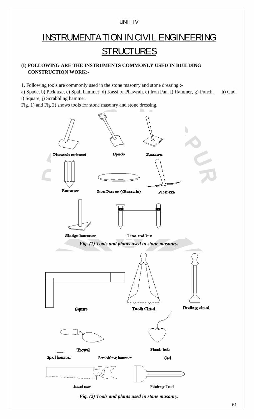
61
UNIT IV
INSTRUMENTATION IN CIVIL ENGINEERING
STRUCTURES
(I) FOLLOWING ARE THE INSTRUMENTS COMMONLY USED IN BUILDING CONSTRUCTION WORK:- 1. Following tools are commonly used in the stone masonry and stone dressing :- a) Spade, b) Pick axe, c) Spall hammer, d) Kassi or Phawrah, e) Iron Pan, f) Rammer, g) Punch, h) Gad, i) Square, j) Scrabbling hammer. Fig. 1) and Fig 2) shows tools for stone masonry and stone dressing.
Fig. (1) Tools and plants used in stone masonry.
Fig. (2) Tools and plants used in stone masonry.

62
2. Various tools for excavation: - Fig a) shows tools of excavation. 3. Hoisting equipments like various types of cranes. 4. Derricks, Guy Derrick, Scotch derrick. 5. Dumpers. 6. Tractors. 7. Bulldozers. 8. Drag lines. 9. JCB. 10. Drag lines. 11. Various rollers for compaction. 12. Graders. 13. Tilting mixers. 14. Vibrators. Some of the instruments are explained in following sections. 1) CRANES:-
Normally cranes are used in building construction for lifting and erecting pre-fabricated units and for other purposes. Depending upon the nature of work and load to be lifted different cranes are used. Tower cranes are the non-swinging type cranes mounted on high steel tower. These cranes are suitable for tall structures, high rise building construction of buildings in congested areas in assembling of high industrial plants. With tower cranes loading and unloading of heavy structural pieces is done quite easily. The tower on which crane is mounted has a truss structure welded with bars and angles and channels generally jib is attached to last tower. The tower cranes are available in different forms with a horizontal jib carrying a saddle or trolley or alternatively with a lifting or derricking jib with lifting hook at extreme end. The horizontal jibs can bring the load closer to tower while luffing jibs are used to clear obstruction.
The tower crane are of following types :- 1. Self supporting static tower crane. 2. Supported static tower crane. 3. Travelling tower crane. 4. Climbing crane.
1. Self Supporting Static Tower Crane :-
The self supporting cranes have a static tower with rotating or slewing tower. The maximum height of tower is 27.4 m and the maximum height to which load is attached is 26.2m. The hoisting radius will be 1.1 rpm. The crane is operated either from ground level as well as the operator cabin provided above the tower.
2. Supported static tower crane :- A stationary (static or fixed) crane, either freestanding or supported by the building, can be erected on a suitable concrete base or other substantial mount. Increases in the height of the crane are made possible through the use of the telescoping mechanism of the crane, permitting the addition of sections.
Fig. (3) Self supporting static tower crane.

63
Fig. (4) Supported Static tower crane.
1. Travelling tower crane :- The addition of a rail-mounted undercarriage to the stationary crane allows free traveling under load
on either straight or curved tracks. This is particularly useful when the application requires a larger area than the working radius the crane permits. There is also a truck-mounted tower crane, and attachments that convert conventional crawler or truck cranes to tower cranes (Figure 6).
Fig. (5) Travelling tower crane. 3. Climbing crane :-
With their working radiuses varying from 30m to 70m, cranes are famous for their large operating ranges, varied working methods and wide uses. This series of tower cranes has a horizontal jib frame, a jib-trolley radius-changing mechanism and a hydraulic self-raising mechanism. It is original in design, reliable in operation and satisfactory in shape. Equipped with all necessary safety devices, these cranes show a good speed-control capacity, satisfactory operating stability and high work efficiency. They can be widely used for the construction of high-rise hotels, residential buildings, high-rise industrial buildings, large-span factory buildings and tower-like buildings like tall chimneys.
Fig. (6) Climbing crane.

64
2) DERRICKS:- These are mounted on triangulate frame and their load carrying capacity is 5-10 MT and its jib
length is 30 m. It is mainly used for factory columns, trusses, frames, etc. The derricks are classified as: - (a) The Guy derrick, (b) Scotch derrick.
1. The Guy Derrick :- In this type of crane vertical post is longer than jib and is mounted on the basement and held by five or more anchored guy ropes. These are simple type of static crane powers by diesel engine. The shorter lib has advantage that at minimum radius it can rotate through full 3600 clearing the guys by passing underneath them
Fig. (7) The Guy Derrick.
1. The Scotch Derrick :- It has short vertical centre post and a jib is usually two times as long as centre post. These
are capable of slewing 2700 only as they are restricted in further rotational movement by sloping lattice guy. The centre post carried the hoisting slewing and luffing gears together with the operator and his cab. Most of the scotch derricks are stationary and requires firm anchorage and heavy ballasting to hold down the feet of stays and the base of the centre post. The weight on foot of each stay, should be such that it should be four times the rate of maximum lifting capacity foot derricks. The capacity of scotch derricks are upto 200 tonne.
Fig. (8) The Scotch Derrick. 3) BULLDOZERS:-
Bulldozers are the cheapest and first choice for excavating and moving earth upto 100 m. These are either crawler or wheel type. Amongst this crawler type is mostly used. In bulldozer cutting blade is mounted at the direction perpendicular to the direction of travel. And when cutting blade is set at the angle with the direction of travel it is called as angle dozer and these angle dozers are used inside hill works where the material is to be pushed down the slope. The bulldozer pushes earth forward while angle dozer

65
pushes it forward and to one side. When ‘V’ shaped blade is attached in front side and purpose of providing V shape blade is to cut the trees and to drive out roots it is called as tree dozer and if blade attached can be tilted to rise from one end by 20 to 25 cm it is called tilt dozer.
Fig. (9) Bulldozer. 4) WHEEL LOADER (JCB):- Excavation machine made up of a wheel tractor, a backhoe and a front hand loader. This type of excavator is manufactured by JCB sales limited that are why the name is JCB. It is typical type of multi-purpose excavator machine which is based upon a tractor power unit and very popular in the construction industry and commonly used by building contractors due to its versatility of multi-purpose working. JCB as an excavators are available with small to medium size. The tractor is normally a diesel-powered wheeled vehicle in which a hydraulically controlled loading shovel is fitted at the front and a hydraulically controlled back acting bucket or hoe at the rear of the vehicle.
Fig. (10) A typical section of JCB.
5) DRAGLINE (EXCAVATOR MACHINE):- It is the most flexible excavating tool. However they are more suitable where swampy condition prevent other equipments from being used. It has more reach than a shovel both for excavating as well as disposal. It can dig far below its base almost in any location. These are classified on the basis of mounting whether truck mounted, crawler tractor mounted or wheel mounted. The operating cycle of the dragline consists of five basic steps: 1. The empty bucket is positioned, ready to be filled. 2. The bucket is dragged toward the dragline to fill it. 3. The filled bucket is simultaneously hoisted and swung over to the spoil pile. If the swing motion must be slowed to permit hoisting, the dragline is said to be hoist critical. When hoisting to the dump position is completed before the boom is in position to dump, the dragline is said to be swing critical. 4. The material is dumped on the spoil. 5. The bucket is swung back to the cut while simultaneously being lowered and retrieved to the digging position.

66
Fig. (11) A typical section of Dragline (Excavator machine). (II) FOLLOWING ARE THE INSTRUMENTS COMMONLY USED IN COMPACTION WORK:-
To increase the bearing capacity, strength of earth structure the soil stabilization and compaction is necessary. Compaction is achieved by applying proper methods and by using many types of rollers depending upon the requirement of degree of compaction. Many types of compacting equipments are available like steel rollers, vibration rollers, tamping rollers, pneumatic rollers all these are manually propelled or mechanically operated. 1) PLAIN ROLLERS:- The plain steel rollers weighing from 5m to 15m are used for ordinary rolling work where deep compaction is not required. It consists of two axle and three wheels of which front one is used for steering while rear two wheels are used as driving units. A three wheel tandom rollers differs from two wheels in that it has three drums and three axle and are designed in terms of MT that means if it is indicated as 10/12 MT means the minimum weight of machine is 10 tonnes.
Fig. (12) Plain Roller 2) SHEEP FOOTED ROLLERS:- Whenever the compaction is to be done to a great depth the place like in embankment or canal sheep foot rollers are used. The sheep foot rollers consist of a hollow steel drum around its periphery of which welded projections or feet just like that of sheep are used. These are varies from 15-20 cm long. In the working of these rollers soil is supposed to be compacted and consolidated. When the compression by projecting teeth is not more than 12mm deep and then top layer is finished with smooth wheel roller. These rollers are called as temping rollers. The pressure variation below its feet is 4 to 7 kg/cm and 25 to 70 km/cm for light heavy rollers respectively.
Fig. (13) Sheep footed Roller

67
3) PNEUMATIC ROLLERS:- The pneumatic-tired rollers are widely used for compaction of subgrades, bases, bituminous
mixes, and many types of material. They have rubber tires instead of steel tires or drums and generally feature two tandem axles, with three or four tires on the front axle and four or five tires on the rear. They are aligned so the rear tires cover the spaces left between the tracks of the front tires. The tires are mounted in pairs that can oscillate, or singly with spring action, so tires can move down into soft spots that would be bridged by steel drum. The rubber tires add to their downward pressure a kneading effect, as material is pressed toward spaces between the tires. Pneumatic-tired rollers can be ballasted to adjust the weight. Depending on size and type, the weight may vary from 10 to 35 tons. However, more important than gross weight is the weight per wheel for the material being compacted. Pneumatic rollers ballast with water are top-heavy and are very unstable when operating on uneven terrain.
Fig. (14) Pneumatic Roller 4) VIBRATORY ROLLERS:-
Vibratory rollers are the recent development of compacting dry and lean concrete. A heavy roller which vibrates while vibrates while rolling is used for the compaction of dry lean concrete. Mainly for construction of dams and pavements.
Fig. (15) Vibratory Roller 5) TILTING TYPE MIXERS:-
In tilting type mixers the drum can be tilted at one side after proper mixing is done and effective mixing of concrete can be carried out simultaneously. These are having capacity in between 0.1 m3 to 0.2 m3. In tilting type drum mixers drum is made up of cast iron and steel plate body rotates across its axis inside the drum. For continuous agitation blades are fixed. While charging drum all ingredients in required specification are poured into the hopper and then with the help of winding and unwinding of wire rope the material is charged into drum through the hopper. Hopper is also made up of steel plate. The clutch and brake control the movement of hopper. The water is added as per requirement and then drum is rotated at specific required rpm and then it is tilted on other side and the mixed concrete is spilled out through the drum and then utilized for site work. Due to their portability and easy operations these are preferred on site. These can handle aggregate size of 15 cm to 20cm.
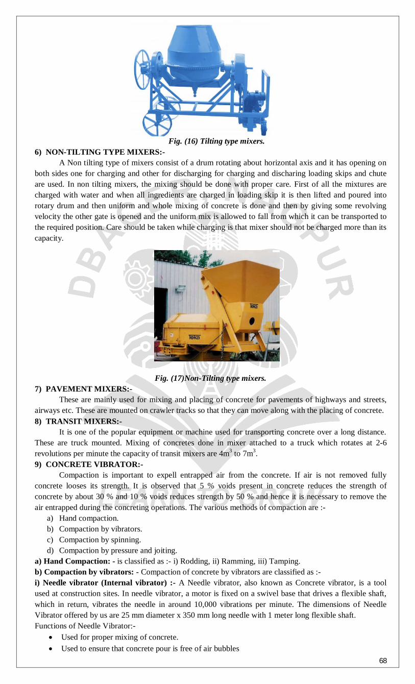
68
Fig. (16) Tilting type mixers. 6) NON-TILTING TYPE MIXERS:- A Non tilting type of mixers consist of a drum rotating about horizontal axis and it has opening on both sides one for charging and other for discharging for charging and discharing loading skips and chute are used. In non tilting mixers, the mixing should be done with proper care. First of all the mixtures are charged with water and when all ingredients are charged in loading skip it is then lifted and poured into rotary drum and then uniform and whole mixing of concrete is done and then by giving some revolving velocity the other gate is opened and the uniform mix is allowed to fall from which it can be transported to the required position. Care should be taken while charging is that mixer should not be charged more than its capacity.
Fig. (17)Non-Tilting type mixers. 7) PAVEMENT MIXERS:- These are mainly used for mixing and placing of concrete for pavements of highways and streets, airways etc. These are mounted on crawler tracks so that they can move along with the placing of concrete. 8) TRANSIT MIXERS:- It is one of the popular equipment or machine used for transporting concrete over a long distance. These are truck mounted. Mixing of concretes done in mixer attached to a truck which rotates at 2-6 revolutions per minute the capacity of transit mixers are 4m3 to 7m3. 9) CONCRETE VIBRATOR:- Compaction is important to expell entrapped air from the concrete. If air is not removed fully concrete looses its strength. It is observed that 5 % voids present in concrete reduces the strength of concrete by about 30 % and 10 % voids reduces strength by 50 % and hence it is necessary to remove the air entrapped during the concreting operations. The various methods of compaction are :-
a) Hand compaction. b) Compaction by vibrators. c) Compaction by spinning. d) Compaction by pressure and joiting.
a) Hand Compaction: - is classified as :- i) Rodding, ii) Ramming, iii) Tamping. b) Compaction by vibrators: - Compaction of concrete by vibrators are classified as :- i) Needle vibrator (Internal vibrator) :- A Needle vibrator, also known as Concrete vibrator, is a tool used at construction sites. In needle vibrator, a motor is fixed on a swivel base that drives a flexible shaft, which in return, vibrates the needle in around 10,000 vibrations per minute. The dimensions of Needle Vibrator offered by us are 25 mm diameter x 350 mm long needle with 1 meter long flexible shaft. Functions of Needle Vibrator:-
Used for proper mixing of concrete. Used to ensure that concrete pour is free of air bubbles

69
Used to ensure that the concrete pour is even with a smooth finish.
Fig. (18) Needle Vibrator. ii) Form work vibrator (External vibrator) :-
External Vibrator is more suitable vibrator for concreting the column, thin walls or in casting of precast members. It gives a good finish to the concrete surface. Compaction by external vibrator or formwork vibrator is particularly used to the area where reinforcement, lateral ties and spacers becomes more congested and gives more interfere to the internal vibrator. External vibrator consume more power than the internal vibrator because vibration is given to the concrete indirectly through the formwork.
Fig. (19) External Vibrator iii) Table vibrator:- Table vibrators are used to compact concrete to avoid blowholes on concrete slabs.
Fig. (20) External Vibrator. vi) Surface vibrator (Screed vibrator):-
Surface vibrators are also known as screed board vibrators. These are particularly used where the compaction is to be done for thin concreting members such as floor slab, roof slab, road surface etc. where other type of vibrators is not suitable. These are small vibrators placed on the screed board. These screed vibrators are not effective beyond 15 cm. NDT
Quality control method that does not damage or destroy the material or product being tested. Performed on a finished item instead of on a material sample, it uses infrared radiation, radiography, ultrasound, x-rays, and other techniques to detect fatigue effects, structural flaws, and other such defects.
ULTRASONIC TESTING
The basic principle of this method of testing is that the velocity of an ultrasonic pulse through concrete is related to its density and elastic properties. Some care is necessary when testing, but an experienced operator may obtain a considerable amount of information about a concrete member. The advantage of this method is that the pulse passes through the complete thickness of the concrete so that significant defects can be detected. The method also determines the measurement of concrete deterioration which might have occurred due to age or through the action of fire, frost or chemical attack.
The measurement of concrete uniformity Determination of the presence or absence of voids, cracks and other imperfections

70
Measurement of layer thickness and elastic modulus Determination and monitoring of concrete strength
Quality control and inspection of concrete structures is the primary application for the Ultrasonic Concrete Testing System. It uses measurement of the speed of ultrasonic pulses through the concrete to correlate concrete strength to standard strength. It will identify non-homgeneous conditions in the structure such as honeycombs, voids, cracks, frozen concrete, etc. Use it to survey complete structures, new, old, fire damaged or weathered. The large LCD display shows a graphic waveform and the elapsed time in 0.1 microsecond increments. The system includes two 54 KHz transducers with connecting cables, readout unit, power cord, built-in rechargeable batteries, carrying case and coupling grease. The system facilitates automatic calculation of: • Ultrasonic Pulse Velocity • Poisson's Ratio • Modulus of Elasticity
Environmental Engineering:
SPECTROPHOTOMETER Instrument used to measure the intensity of wavelengths in a spectrum of light compared with the intensity of light from a standard source. II Device for measuring the brightness of the various portions of spectra. Principle:
Light Intensity Change : By Absorbance or Transmittance Quantity : Using Absorbance
Use: To determine the intensity of transmitted light To Determine the absorbance or transmittance Used in dyes industry To determine colour impurities in water
Strain Gauges:
It is passive resistive transducer. This is a transducer which transforms mechanical elongation and compression into resistance change. The elongation or compression per unit length of conducting wire is called as strain. The strain gauge is an example of a passive transducer that uses the variation in electrical resistance in wires to sense the strain produced by a force on the wires. (2) Applications:
The strain gauges find application in following areas : 1) Experimental stress analysis 2) Load cells 3) Torque meters 4) Diaphragm type pressure gauges 5) Accelerometers 6) Flow meters 7) Temperature sensors Electric Resistance Strain Gauges The strain gage is one of the most widely used strain measurement sensors. It is a resistive elastic unit whose change in resistance is a function of applied strain.
where R is the resistance, ε is the strain, and S is the strain sensitivity factor of the gage material (gage factor in some books).

71
Among strain gages, an electric resistance wire strain gage has the advantages of lower cost and being an established product. Thus it is the most commonly used type of device. Other types of strain gages are acoustic, capacitive, inductive, mechanical, optical, piezo-resistive, and semi-conductive. A wire strain gage is made by a resistor, usually in metal foil form, bonded on an elastic backing. Its principle is based on fact that the resistance of a wire increases with increasing strain and decreases with decreasing strain, as first reported by Lord Kelvin in 1856.
Management of Utilities using telemetry:
Definition of Telemetry:
A technology that allows data measurements to be made at a distance is called as telemetry. The word is derived from Greek roote. The tele means remote and metron means measure. System which needs external instructions and data so as to operate require the counter part of telemetry. In short, a process by which the measured physical quantities such as temperature level, pressure, flow, displacement, velocity, acceleration, relative humidity, speed etc. are transrmtted to a suitable and convenient remote station or to a process etc. is called as telemetry.
Basic Telemetry System:
It consists of the following building block which transmits data to the desire destination. A measuring instrument: It measures pressure, flow, temperature, level or any other variable. A conversion element or transducer: It converts the measured variable into proportional electrical, hydraulic or pneumatic signals. A transmitter: It transmits the measured variable to a receiver. A receiver: It receives the transmitted variable.
Applications and Management of utilities using telemetry
There are several applications of telemetry; some of them are briefly explained as below:
1. It is used in Meteorology by weather balloons for transmitting meteorological data. 2. Telemetry is used to transmit drilling mechanics and formation evaluation information uphole, in
real time, as a well is drilled in oil and gas industries
3. It is also used in agriculture, in which wireless weather stations play a major role in disease prevention and precision irrigation. Telemetry stations transmit parameters necessary for decision-making to a base station to know the air temperature and relative humidity precipitation and leaf wetness (for disease prediction models), solar radiation and wind speed, water deficit stress leaf sensors and soil moisture.
4. Water resources sewer utilities can be well monitored and managed by telemetry.
5. Telemetry play a vital role in water management including water quality and stream gauging
functions. Major applications include AMR i.e. Automatic Meter Reading, ground water monitoring, leak detection in distribution of pipelines and equipment surveillance.
6. Telemetry is used to manage the complex system such as missiles, spacecraft, oil rigs and chemical
plants since it allows the automatic monitoring, altering and recordkeeping necessary for efficient and safe operation.
7. Telemetry is used in energy monitoring. In factories, buildings and houses, energy consumption system is monitored at multiple locations; related parameters such as temperature etc. are sent via wireless telemetry to a central point. The information is collected and processed, enabling the most efficient use of energy. Telemetry system also manages predictive maintenance.
8. PROCESSING DATA FROM TELEMETRY The meter readings from reservoirs are useful information for managing the distribution system and helps in preventing overflow from reservoirs. However the effectiveness of Telemetry in pumping operations is dependent on reliability of instrumentation for measuring flows, pressures, KWh meters, etc. Standard practice is to calculate pump efficiency and water audit calculations on a monthly basis.

72
Telemetry can also be used to supervise water hammer protection system wherein the pump failures are linked to initiate measures to prevent occurrence of water hammer.
Fig. SCADA system integrating industrial process and operator panel. SCADA System. Supervisory Control and Data Acquisition Instead of manual review of data collected by telemetry and initiating action manually, if telemetry is extended to include actions based on the data for remote control of pumps and other equipment then such a system is known as SCADA. Supervisory Control and Data Acquisition (SCADA) is a computer aided system which collects, stores and analyses the data on all aspects of O&M. The operating personnel can retrieve the data and control their operations and sometimes the system itself is programmed to control the operations on the basis of the acquired data. SCADA enhance the efficiency of the O&M personnel who are better informed about the system and hence are in full control of the operations. Whether in a telemetry system or a SCADA system up-to the minute real time information is gathered from remote terminal unit located at the water treatment plant, reservoir, flow meter, pumping station etc. and transmitted to a central control station where the information is updated, displayed and stored manually or automatically. In a SCADA system the information is linked to a supervisory system for local display, alarm annunciation etc. which may be linked to remote control of pumping operations or operation of valves etc. Data collection in SCADA SCADA systems will have probes/sensors which will sense and generate signals for the level, pressure and flow in a given unit and transmit the signals for storage and analysis in the computer. The signals are transmitted by radio, by Telephone, microwave satellite or fiberoptic transmission systems. The signals transmitted are stored as data, analysed and presented as information. SCADA systems can include the network diagrams of the distribution system of which detailed sketches of a particular area can be viewed by the operator if necessary to observe the current operating data such as flow, pressure, level or residual chlorine. SCADA systems in Water distribution are programmed for collection and processing of following information. • to monitor levels in Service reservoirs, pressures and flows in a distribution system • to monitor and store data on levels in SRs, or flows/quantity of delivered into a SR or pressures of distribution system and generate alarms for threshold values of levels, flows and pressures to initiate operation of valves and pumps • to monitor and store data on operation of pumps such as Voltage, amperes, energy consumed, operating times and down times of pumps • to measure and record chlorine residuals and generate alarms at thresh hold values of residual chlorine in the distribution systems.

73
Working of SCADA The SCADA works at the application layer i.e. the layer at which the end user or operator/supervisor interfaces to the process controller and I/O devices. The SCADA system includes the basic blocks such as :
Input output signal hardware or instrumentation, The process controller. The HMI software and display. Network communication. Process database and Controller interface hardware and software.
This whole system operates either in a stand alone mode or in networked mode. In the networked mode the all possible nodes connected to the supervisory controller usually called as master is connected to all possible and required slaves.All these slaves has unique slave address and the supervisory controller can select the specific slave by placing the appropriate slave address, followed by the datagram, that includes the targeted message to specific slave and the compulsory pre-amble and post-amble message frame overheads. This software addressing for the multiple clients and controllers connected to the supervisor reduces the wiring complexity of the system upto the considerable level.
Fig. shows the functional block diagram of SCADA system.
SUSTAINABLE DEVELOPMENT It is defined in the report of the 1987 world commission on environment and development, our common future as development which meets the needs of the present without compromising the ability of future generation to meet their own needs. Sustainable development simply means development that genuinely sustains and improves economic, social and environmental well being with no major trade off, locally and globally, now and in the future. Role of Engineers in Sustainable Development:
Engineers can play a significant role in ensuring sustainable solutions available, considered and implemented.
In contrast, the applied knowledge of this engineering community has been largely absent from this policy debate, despite this fact which engineers use science to plan, build and operate this infrastructure which may directly contribute to solutions and sometimes problems of environmental degradation.
Re-address engineering responsibilities by incorporating sustainable developments principles into the codes of ethic of these engineering organisations throughout this world.
Incorporate long term environmental impacts and costs into this analysis of alternate solutions being

74
considered. Information exchange is this comer stone of sustainable development and technological innovation.
Engineers can use wenet to share ideas, conduct business and develop sustainable engineering solutions.
The world engineering partnership for sustainable development with its partners is creating an global communications network with engineers to provide leadership and practical content to the concept of sustainable development wenet represents is a major step in linking engineers and sharing technology with developed and developing nations. Hence engineer can use wenet for sustainable development.
Near form solutions to critical global environmental issues such as fresh water and global climate change exist, for application in both developed and developing countries and for all regions of the world. CONCEPT OF GREEN BUILDINGS Green building is also termed as green construction or sustainable building. Green building is that structure which is built by using the process which is environmentally responsible and resource-efficient throughout a building's life-cycle from siting to: (i) Design (ii) Construction (iii) Operation (iv) Maintenance (v) Renovation and (vi) Demolition
To achieve the effective target of greens buildings, there should be a close co-operation of the design team, the architects, engineers and the client at all stages of the desired project.
The green building practice expands and complements the classical building design concerns of economy, utility, durability, eco-friendly and comfort.
Objective of green building: The common objective of green building is to design the building in such way that it should reduces the overall impact of the built environment on human health and the natural environment Following are the main and common objective of the green building
Efficient utilisation of energy, water and other resources Protecting occupant health and improving employee productivity Reducing waste, pollution and environmental degradation Recycling of waste material Maximum utilisation of eco-friendly material or natural material which are available locally.
Sustainable design and green architecture. Green Buildings Retain the Environment at the location of the Building. Suppose we propose a multi-storied office complex to accommodate thousands of officers and staff, it requires a vast area. Therefore selection of a site for such a building complex should consider retention of local vegetation, wild life, natural water courses etc. Either a site with bio diversity should be avoided or the building should be planned to reduce site disturbance.
Fig. Conceptual drawing of Green Building

75
LEED CERTIFICATION Meaning of LEED is leadership in energy and environmental design. LEED consists of a suite of rating system for the design, construction and operation of high performance green buildings; homes and neighborhoods. Certification is granted solely by the Green Building Certification Institute (GBCI), which is responsible for the third party verification of project compliance with LEED requirements. LEED certification assures that a building project is environmentally responsible; profitable and a healthy place to work.
Ratings for LEED certification exist for the following categories 1. New construction 2. Existing buildings 3. Core and shell 4. Schools 5. Commercial buildings and its interiors 6. Homes 7. Healthcare facilities Neighborhood development
LEED certified buildings has the following salient features 1. It has lower operating costs 2. It has a higher asset value 3. It conserve both water and energy 4. It is healthier and safer for occupants 5. It reduces green house gas emissions 6. It show the owner's commitment to environmental stewardship and social responsibility 7. It qualify for tax rebates, zoning allowances and other incentives LEED certification is obtained after submitting an application documenting compliance with the requirements of the rating system as well as paying registration and certification fees. In order to establish a building's points awards in each credit category, buildings applying for certification are compared with a theoretical baseline defined by a LEED methodology