bcy - carly : the international expert in refrigeration … technical documentation...bcy-p14.2 c c...
TRANSCRIPT
Refrigeration & Climate Components Solutions BCY-P14.1
C
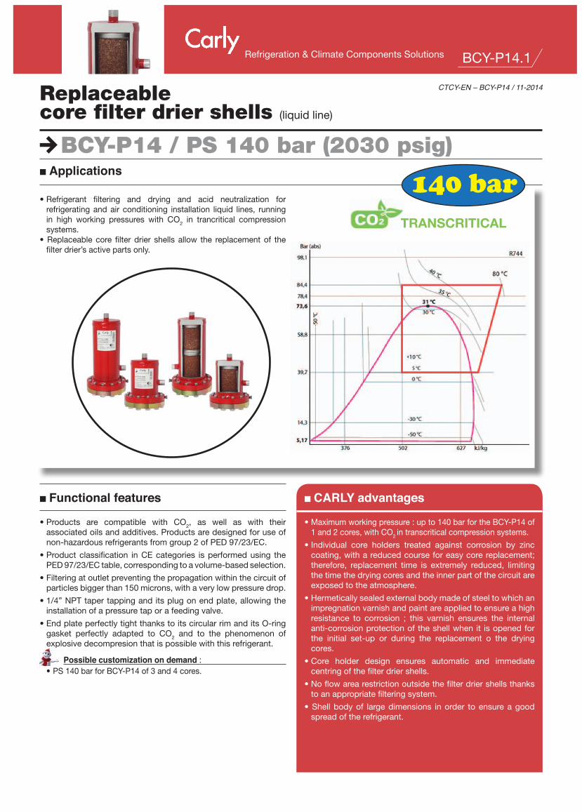
BCY-P14 / PS 140 bar (2030 psig)
Replaceablecore filter drier shells (liquid line)
CTCY-EN – BCY-P14 / 11-2014
•Products are compatible with CO2, as well as with theirassociatedoilsandadditives.Productsaredesignedforuseofnon-hazardousrefrigerantsfromgroup2ofPED97/23/EC.
•Productclassification inCEcategories isperformedusing thePED97/23/ECtable,correspondingtoavolume-basedselection.
•Filteringatoutletpreventingthepropagationwithinthecircuitofparticlesbiggerthan150microns,withaverylowpressuredrop.
•1/4”NPTtapertappinganditsplugonendplate,allowingtheinstallationofapressuretaporafeedingvalve.
•EndplateperfectlytightthankstoitscircularrimanditsO-ringgasket perfectly adapted to CO2 and to the phenomenon ofexplosivedecompresionthatispossiblewiththisrefrigerant.
Possible customization on demand :•PS140barforBCY-P14of3and4cores.
n Functional features n CARLY advantages
•Maximumworkingpressure:upto140barfortheBCY-P14of1and2cores,withCO2intranscriticalcompressionsystems.
•Individual core holders treated against corrosion by zinccoating,withareducedcourseforeasycorereplacement;therefore, replacement time is extremely reduced, limitingthetimethedryingcoresandtheinnerpartofthecircuitareexposedtotheatmosphere.
•Hermeticallysealedexternalbodymadeofsteeltowhichanimpregnationvarnishandpaintareappliedtoensureahighresistance to corrosion ; this varnish ensures the internalanti-corrosionprotectionoftheshellwhenit isopenedforthe initial set-up or during the replacement o the dryingcores.
•Core holder design ensures automatic and immediatecentringofthefilterdriershells.
•Noflowarearestrictionoutsidethefilterdriershellsthankstoanappropriatefilteringsystem.
•Shellbodyof largedimensions inorder toensureagoodspreadoftherefrigerant.
n Applications
•Refrigerant filtering and drying and acid neutralization forrefrigeratingandair conditioning installation liquid lines, runningin high working pressures with CO2 in trancritical compressionsystems.
• Replaceable core filter drier shells allow the replacement of thefilterdrier’sactivepartsonly.
TRANSCRITICAL
140 bar

Refrigeration & Climate Components SolutionsBCY-P14.2
C
BCY-P14 / PS 140 bar (2030 psig)
Replaceablecore filter drier shells (liquid line)
CTCY-EN – BCY-P14 / 11-2014
•Filter drier shells are to be mounted onthe liquid line between the receiver andtheexpansionelement.
•The refrigerant flow direction, indicatedbyanarrowonthefilterdriershells’tags,shouldbecompliedwith.
•Assembly can be performed in anyposition,butnotverticallywiththeoutletconnectionorienteddownwards.
•During filter drier shells assembly,provide for sufficient course to allowcorereplacement(refertosizesL2inthetechnicalfeaturestable).
•The connection to the installation, bysoldering or welding, of the filter shell,must be done only after removing theclosingflange,itsgasketandtheinternalcoreholders.
• The O-ring gasket of the closing flange
mustbelubricatedbeforeitsinstallation,withrefrigeratingoilcompatiblewiththeoiloftheinstallation.
•We recommend to clean and to protectthe connections of the filter drier shellwith appropriate products in order toensureagoodresistancetocorrosionoftheaffectedareas.
•Becarefultoproperlyselectthesolenoidvalves located downstream of the filterdrier shells; their oversizing could causeliquid hammer phenomena hinderingthe filter drier shells’ proper mechanicalbehaviour; these liquid hammerphenomena can originate from othersources,inlong-pipinginstallations.
•Neverinstallfilterdriershellsinanareaofthecircuitthatcanbeisolated.
•Never trap refrigerant in its liquid state
(between a check valve and a solenoidvalve,forinstance).
•Thefilterdriershells’efficiencyandtherefrigerant’smoisturecontentshouldbecheckedusingVCYL-Pliquidsightglasses.
•Makesurethatthepipingcansupportwithoutdeformationtheweightofthefilterdriershell;otherwise,provideforaclampofthefilterdriershellwithaclamponastablepartoftheinstallation.
•IncaseofremplacementofremovableelementsoffilterdriershellsBCY-P14(flange,screw,gasket),itismandatorytouseonlyidenticalcomponents,suggestedbyCARLYinthelistofsparepartsattheendofthischapter.
Top core holder with outlet screen
Adapter CCY A
CCY-HP, PLATINIUM, N
Bottom core holder
n Warning
n General assembly precautions
Beforeselectingorinstallinganycomponent,pleaserefertothechapter0ofCARLYtechnicalcatalogue-WARNING.
The installation of a component ina refrigeration system by a skilledprofessional,requiressomeprecautions:•Some are specific to each component,
and in this case, theyare specified in theRECOMMENDATIONS SPECIFIC partdefinedhereafter;
•OtheraregeneraltoallCARLYcomponents,
they are presented in the chapter 115 –GENERAL ASSEMBLY PRECAUTIONS.
n Specific recommendations to replaceable core filter drier shells BCY-P14

Refrigeration & Climate Components Solutions BCY-P14.3
C
BCY-P14 / PS 140 bar (2030 psig)
CTCY-EN – BCY-P14 / 11-2014Replaceablecore filter drier shells (liquid line)
n Special precautions for components used with CO2 in transcritical systems
•Themaximalworkingpressureandthepowervariationsoftheinstallationmustbetakenintoaccountasofitsdesign,inordertoselectallthecomponentsconsequently.
•Thepressureofthecircuitduringthestopphasesmustalsobetakenintoaccount,becauseitcanbeveryhigh,duetothepressureequalizationaccordingtotheambienttemperature;severalsolutionsexisttolimitandcontrolthispressurewhentheinstallationisstopped.
- Designoftheinstallationallowingtoresisttothispressure.- Implementationofa«buffer»volumeofstorageorexpansion(receiver).- Installationofasecondarycircuitwithvalveorsolenoidvalve,allowingthefluidtransfertothecoldestpoint,or
thelesshighinpressureoftheinstallation.- Implementationofasmall separate refrigerationunit, tomaintain the liquid temperatureatapressure lower
thanthemaximalworkingpressure;itissofarthemosteffectivetechnicalsolution,butwithamajordrawback,whichisthepowerfailure(safetyunittobeconsidered,orbackuppowersupply).
•TheimplementationontheliquidlineofafilterdriershellBCY-P14equippedwithdryingcoresCCY 48 HPorPLATINIUM 48, ishighlyrecommended.Seriousproblemscanoccurinthepresenceofmoisture,suchasexpansionvalveblockingandformationofdryiceandevencarbonicacid.Toavoidthis,itisimperativetolimitthecircuitopeningsinordertoavoidairintroduction,causingthecondensationinthepipes,andtoproceedtoahighevacuationoftheinstallation,beforeanycommissioningorrestarting.
•ForanoperationwithCO2atlowtemperature,providethermalinsulationonthecomponentswhichcanbecoveredbyfrost.
•There isno incompatibilitybetweenCO2and themainmetallicmaterialscommonlyused in refrigerationsystems (steel,copper,brass...)
•Ontheotherhand,thereisarealcompatibility issuebetweenCO2andpolymers.Forexample,swellingphenomenaandinternalexplosionofthesealarepossible.CarlyfilterdriershellsBCY-P14donothavepolymergasketsdirectlyincontactwithCO2.

Refrigeration & Climate Components SolutionsBCY-P14.4
C
BCY-P14 / PS 140 bar (2030 psig)
1 2
Replaceablecore filter drier shells (liquid line)
CTCY-EN – BCY-P14 / 11-2014
n Core replacement procedure
1•IsolatetheBCY-P14filterdriershell.
2•Purgetheinstallationuptoatmosphericpressure(shellshouldbeemptyofrefrigerants)
3•Removetheendplate.
4•Removethecoreholdersoneaftertheother.
5•Removetheusedcores.
6•Cleanverycarefullythecoreholders,theadapter(CCY A 48)andtheinnerpartoftheshellcase.
7•Replace systematically the O-ring gasket on the end plate, and lubricate it before its installation with refrigerating oilcompatiblewiththeoiloftheinstallation.Attention:thisgasketisspecificforthistypeofshellanditisnotincludedwithCCY48HPandPLATINIUM48cores;itwillhavetobesuppliedseparately,itsreferenceisindicatedinthesparepartslist,intheendofthischapter;checkthecoreholderandcoreendgaskets.
8•Removethecorefromitscanandputitonthecoreholder,separatingbytractionthetwoflangesthatholdthecoreholder(sketch1)
9•Repeattheoperationforeachcoreholder.
10•Quicklyinstallthecoreholderswiththeircoreintheshell,complyingwiththeirmountingorder:thefirstoneholdsthefilterelementsandthelastoneistheoneequippedwiththecompressionspring(sketch2)
11•Reinstalltheclosingflangemakingsurethatthecompressionspringiscorrectlypositionedandgraduallyanduniformlytightentheclosingscrews(refertochapter115ofCARLYtechnicalcatalogue–GENERAL MOUNTING PRECAUTIONS–Criss-crosstightening).Maximumbolttighteningtorque:100N.m.
12•Makesurethattheendplate’s1/4’’NPTtapertappingpresentontheclampofthefiltershellhasbeenproperlypluggedinandsealed.
13•Makevacuumintheinstallationandcheckair-tightnessofthewholesetbeforeputtingbackunderpressure.

Refrigeration & Climate Components Solutions BCY-P14.5
C
BCY-P14 / PS 140 bar (2030 psig)
BCY-P14 485 S/MMS 5/8 BCY-P14 485 S/MMS 16 34 1BCY-P14 487 S/MMS 7/8 BCY-P14 487 S/MMS 22 34 1BCY-P14 489 S 1 1/8 BCY-P14 489 MMS 28 34 1BCY-P14 4811 S/MMS 1 3/8 BCY-P14 4811 S/MMS 35 34 1BCY-P14 4813 S 1 5/8 BCY-P14 4813 MMS 42 34 1BCY-P14 967 S/MMS 7/8 BCY-P14 967 S/MMS 22 68 2BCY-P14 969 S 1 1/8 BCY-P14 969 MMS 28 68 2BCY-P14 9611 S/MMS 1 3/8 BCY-P14 9611 S/MMS 35 68 2BCY-P14 9613 S 1 5/8 BCY-P14 9613 MMS 42 68 2
CTCY-EN – BCY-P14 / 11-2014Replaceablecore filter drier shells (liquid line)
n Selection table
Nota: the diameter of connections must not be inferior to the diameter of the main pipe.
CARLYreferences
Connections
To solder ODF
inch
CARLYreferences
Connections
To solder ODF
mm
Dehydratable refrigerant capacity kg of refrigerant
Numberof coresR744 CO2
24 °C

Refrigeration & Climate Components SolutionsBCY-P14.6
C
BCY-P14 / PS 140 bar (2030 psig)
BCY-P14 485 S/MMS 1 420 141 146 210 273 210 159 114 18BCY-P14 487 S/MMS 1 420 141 146 210 283 210 169 124 18BCY-P14 489 S BCY-P14 489 MMS 1 420 141 146 210 288 210 174 129 18BCY-P14 4811 S/MMS 1 420 141 146 210 296 210 182 137 18BCY-P14 4813 S BCY-P14 4813 MMS 1 420 141 146 210 296 210 182 137 18BCY-P14 967 S/MMS 1 840 141 146 210 422 210 309 124 21BCY-P14 969 S BCY-P14 969 MMS 1 840 141 146 210 427 210 314 129 21BCY-P14 9611 S/MMS 1 840 141 146 210 435 210 322 137 21BCY-P14 9613 S BCY-P14 9613 MMS 1 840 141 146 210 435 210 322 137 21
CARLYreferences
Connectiontypes
(1)
Filteringsurface
cm2
Dimensionsmm
Weight
kgØ1 Ø2 (2) Ø3 L1 L2 E1 E2
BCY-P14 485 S/MMS 2,30 140 / 100 -40 / IIBCY-P14 487 S/MMS 2,30 140 / 100 -40 / IIBCY-P14 489 S BCY-P14 489 MMS 2,30 140 / 100 -40 / IIBCY-P14 4811 S/MMS 2,30 140 / 100 -40 / IIBCY-P14 4813 S BCY-P14 4813 MMS 2,30 140 / 100 -40 / IIBCY-P14 967 S/MMS 4,10 140 / 100 -40 / IIBCY-P14 969 S BCY-P14 969 MMS 4,10 140 / 100 -40 / IIBCY-P14 9611 S/MMS 4,10 140 / 100 -40 / IIBCY-P14 9613 S BCY-P14 9613 MMS 4,10 140 / 100 -40 / II
L1
1
3
L2
E1
E2
2
12 x HM16 x 60
1/4" NPT
Replaceablecore filter drier shells (liquid line)
CTCY-EN – BCY-P14 / 11-2014
n Technical features
(1) Chapter «Connection features and drawings» (refer to chapter 114 to CARLY technical catalogue).(2) Including weld.
CARLYreferences
VolumeMaximalworkingpressure
Workingpressure
(1)
Maximalworking
temperature
Minimalworking
temperature
Workingtemperature
(1)CE
Category(2)V
LPS bar
PS BT bar
TS maxi°C
TS mini°C
TS BT°C
(1) The working pressure is limited to the PS BT value when working temperature is lower than or equal to TS BT value.(2)Classificationbyvolume,accordingtoPED97/23/EC(refertochapter0toCARLYtechnicalcatalogue).

Refrigeration & Climate Components Solutions BCY-P14.7
C
BCY-P14 / PS 140 bar (2030 psig)
CY 37001030 CY 37001090
CY 37001070
CY 37001080 CY 37001030 CY 37001090
CY 37001040 CY 37001080 CY 37001030 CY 37001090
CY 15558700 CY15555200
CTCY-EN – BCY-P14 / 11-2014Replaceablecore filter drier shells (liquid line)
n Spare parts
(1) Gasket delivered with core holders(2)GasketnotdeliveredwithcoresCCY48N,CCY48HPandPLATINIUM48
Shells CARLY References for core holdersQuantity and type of gaskets for use
Core holders gasket (1) End toric gasket (2)
BCY-P6 1 core CY 37001070 1 gasket CY 15558700 1 gasket CY 15555602 BCY-P6 2 cores CY 37001030 + CY 37001090 1 gasket CY 15555200 +1 gasket CY 15558700
CARLYreferences
Part N° Designation Quantity
CY 19900700 1 + 2 Set of 12 fastening screws for end plate 1 CY 33301204 3 + 8 End plate + gasket 1 CY 37001030 4 Core holder ( 2 cores ) 1 CY 37001070 4 Core holder ( 1 core ) 1 CY 37001090 4 Core holder ( 2 cores ) 1 CY 11010750 5 Adapter for core holder 1 CCY A 48 6 Adapter for end core holder 1 CY 15555200 7 Adhesive gasket for core holders : CY 37001030, CY 37001040 et CY 37001080 1 CY 15555602 8 End toric gasket 1 CY 10810010 9 1/4” NPT phosphate plug for end plate 1
2
3
9
7
8
1
6
4
5
5
2
3
9
7
8
1
6
4
5
5