bdd from book
TRANSCRIPT
II
,I II
Ir
I
"
200 201
Algorithms for VLSJ Design Automat'100library ieee;
use ieee.stdJogic_II64.a1I;
entity example is
port (xl, x2, x3, x4, x5: in stdJogic;yl, y2: out stdJogic);
end example;
architecture behavioralof exampleisbegin
react:process (xl, x2,x3,x4,x5)begin
ifxl ='I' and x2='0'then
yl <= x3and x4;y2 <= x3or x4;
elsifx2='I'then
yl <= not (x3and (x4or x5»;y2 <= '-';
elseyl <= '-';y2 <= '0';
end if;end processreact;
end behavioral;
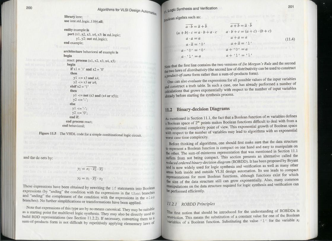
Figure 11.5 The VHDL code for a simple combinational logic circuit.
and the dc-sets by:
Yl = Xl .X2 .X2
r
Y2 =Xl . x2 . X2
These expressions have been obtained by rewriting the if statements into Booleanexpressions (by "anding" the condition with the expressions in the then branchesand "anding" the complement of the condition with the expressions in the elsebranches). No further simplifications or transformations have been applied.
Note that expressions of this type are by no means canonical. They may be suitableas a starting point for multilevel logic synthesis. They may also be directly used tobuild BDD representations (see Section 11.2.2). If necessary, converting them to asum-of-products form is not difficult by repetitively applying elementary laws of
1 L.ogicSynthesis and Verification1.
800lean algebra such as:
a.b=a+b
(a + b). c = a. b + a. c
a+b=a.ba . b + c = (a + c) . (b + c)
a+a=a (11.4)a.a =aa .a= '0' a+a= '1'
a+ '0' =aa. '0' = '0'a. '1' =a a+ '1' = '1'
Notethat the first line contains the two versions of De Morgan's Rule and the secondthetWOlaws of distributivity (the second law of distributivity can be used to construct
aproduct-o!-sums form rather than a sum-of-products form).
One can also evaluate the expressions for all possible values of the input variables
andconstruct a truth table. In such a case, one has already performed a number ofcalculations that grows exponentially with respect to the number of input variablesalreadybefore starting the synthesis process.
11.2 Binary-decision Diagrams
Asmentioned in Section 11.1, the fact that a Boolean function of m variables definesaBooleanspace of 2mpoints makes Boolean functions difficult to deal with from acomputationalcomplexity point of view. This exponential growth of Boolean spacewithrespect to the number of variables may lead to algorithms with an exponentialworstcase time complexity.
Before thinking of algorithms. one should first make sure that the data structuretorepresent a Boolean function is compact on one hand and easy to manipulate ontheother. The sum-of-minterms representation that was mentioned in Section 11.1suffers from not being compact. This section presents an 'alternative called thereduced ordered binary-decision diagram (ROBDD). It has been proposed by Bryantandis now widely used for logic synthesis and verification as well as many otherareas both inside and outside VLSI design automation. Its use leads to compactrepresentations for most Boolean functions, although functions exist for whichthe size of the data structure still can grow exponentially. Also, many commonmanipulationson the data structure required for logic synthesis and verification canbeperformed efficiently.
11.2.1 ROBDD Principles
The first notion that should be introduced for the understanding of ROBDDs isrestriction.This means the substitution of a constant value for one of the Booleanvariables of a Boolean function. Substituting the value' l' for the variable Xi
'1"1'1111,I jl
,,' n
IP ::11 ql
II
., I'I
lII
202Algorithms for VLSI Design Autorn" I'
.. IO~
(l s iSm) in a function I will be denoted by Ix; and substituting the valu' 0' by IX;'.So: e
Ix; = I(XI, ..., Xi-I, , 1', Xi+l,..., xm)
IX;' = I(XI,..., xi-I, , 0', Xi+I,..., Xm)
The two restrictions are also called the positive and respectively negative cofactors
of I with respect to Xi. Consider e.g. the function I given earlier in Equation (I 1.1):
I = XI .X2 .X3 + XI . X2 . X3 + XI .X2 . X3 + XI .X2 .X3 + XI .X2 .X3 + XI .X2 .x3For this function:
Ix) = X2 .X3 + X2 . X3 + X2 . X3
IXI = X2 .X3 + X2 . X3 + X2 . X3
The two restrictions with respect to a single Boolean variable are used to expressthe identity which is known as the Shannon expansion of a Boolean function f(although the principle was already known to Boolel):
I =Xi . Ix; + Xi . IX;' (I 1.5)
Note that the restriction of a Boolean function is a Boolean function with one variableless than the original function. The recursive application of Equation (11.5) to the twofunctions in its right-hand side will eventually lead to a fully-expanded expression.The recursionstopswhenall variableshavebeenexpandedand the restrictionsIx;and IX;'are equal to either of the constant functions' 0' or ' l' (the number ofvariables, m, is zero for a constant function). The step-by-step full expansion of theexample function mentioned above, taking the variables in the order XI, X2 and X3.results in:
I = XI . (X2.X3 + X2 .X3 + X2 . X3) + XI . (X2 .X3 + X2 .X3 + X2 .X3)
= XI . (X2 . (X3 + X3) + X2 . (X3)) + XI' (X2 . (X3)+ X2 . (X3+ X3))
= XI . (X2 . (X3 . '1' + x3 . '1') + X2 . (X3 . '1' + x3 . '0')) +
XI . (X2 . (X3 . ' 0' + x3 . ' 1 ' ) + x2 . (X3 . ' l' + x3 . '1'))
(11.6)
Irrespective of the many possible initial specifications of a Boolean function, the
full Shannon expansion of the function will lead to a unique representation providedthat the expansion processes the variables in a fixed order. Full Shannon expansionis therefore a canonical form, which is not so surprising as the form enumeratesall points in the input space of the Boolean function (compare the form to the suJJ1of minterms and the truth table). The interesting aspect of the fully expanded forJJ1
I George Boole (1815-1864) is the founder of what is known today as Boolean algebra. Claude Shannon(born in 1916) is especially known as the father of information theory.
11.Logic Synthesis and Verification203
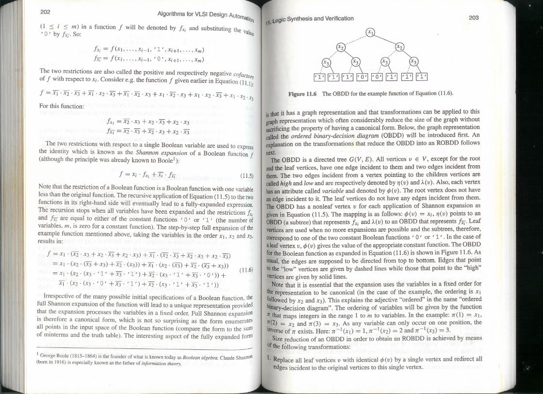
Figure 11.6 The OBDD for the example function of Equation (11.6).
is that it has a graph representation and that transformations can be applied to this
graphrepresentation which often considerably reduce the size of the graph withoutsacrificing the property of having a canonical form. Below, the graph representationcalled the ordered binary-decision diagram (OBDD) will be introduced first. An
explanation on the transformations that reduce the OBDD into an ROBDD followsnext.
The OBDD is a directed tree G(V, E). All vertices v E V, except for the root
andthe leaf vertices, have one edge incident to them and two edges incident fromthem. The two edges incident from a vertex pointing to the children vertices arecalledhigh and low and are respectively denoted by 71(V)and A(V).Also, each vertexhasan attribute called variable and denoted by ifJ(v).The root vertex does not haveanedge incident to it. The leaf vertices do not have any edges incident from them.TheOBDD has a nonleaf vertex v for each application of Shannon expansion asgivenin Equation (11.5). The mapping is as follows: ifJ(v) = Xi, 71(V)points to anOBDD(a subtree) that represents Ix; and A(V) to an OBDD that represents IX;'.Leafverticesare used when no more expansions are possible and the subtrees, therefore,correspondto one of the two constant Boolean functions' 0' or ' l' . In the case ofaleaf vertex v, ifJ(v) gives the value of the appropriate constant function. The OBDDfortheBoolean function ~ expanded in Equation (11.6) is shown in Figure 11.6.Asusual,the edges are supposed to be directed from top to bottom. Edges that pointtothe "low" vertices are given by dashed lines while those that point to the "high"verticesare given by solid lines.
Note that it is essential that the expansion uses the variables in a fixed order foriherepresentation to be canonical (in the case of the example, the ordering is Xlfollowedby X2 and X3).This explains the adjective "ordered" in the name "orderedbinary-decisiondiagram". The ordering of variables will be given by the function11"thatmaps integersin the range I to m to variables.In the example:1T(1)= XI.~(2) = X2 and 1T(3) = X3. As any variable can only occur on one position, thetnverse of 1Texists. Here: 1T-I(XI) = 1,1T-l (X2) = 2 and 1T-I (X3) = 3.
Size reduction of an OBDD in order to obtain an ROBDD is achieved by meansofthe following transformations:
l. Replace all leaf vertices v with identical ifJ(v) by a single vertex and redirect alledges incident to the original vertices to this single vertex.
I!I I
i "II" II
i ..II
Ii il ::1:"I "
II II j
I L, !I
II
, "I
j1rI
IIII
II I II
:I
,II

III..I
Ilf
!~I
~
I
I
hiIIIIII~
IfII
'Ii
(~
II
Algorithms for VLSI Design Automation
I!
II,
It I
"
(b)
(c)
Figure 11.7 The application of Transfonnation Steps 1 (a), 2 (b). and 3 (c) to the OBDDofFigure 11.6 in order to obtain an ROBDD.
2. Process all vertices from bottom to top. If two vertices u and v are found for which
ifJ(u) = ifJ(v), 7](u) = 7](v) and ).,(u) = ).,(v), remove v and redirect to u all edgesoriginally incident to v.
3. If edges v exist for which 7](v) = ).,(v), remove v and redirect to 7](v) all edgesoriginally incident to v.
Figure 11.7 illustrates how the subsequent application of these three steps to theOBDD of Figure 11.6 results in an ROBDD.
Note that any assignment of one of the two Boolean values' 0' and '1' to all
Boolean variables selects a unique path from the root vertex to any of the leaf verticesin the ROBDD. The value of the leaf vertex is the value of the represented Booleanfunction for the combination of input values chosen by the assignment.
1 L.ogicsynthesis and Verification1.205
(a) (b)
Figure11.8 1\\'0 possible ROBDDs for the function of Equation (11.8) using a favorable (a)anda less favorable (b) variable ordering.
The ordering of variables strongly affects the size of an ROBDD. Families ofBooleanfunctions are known that can be characterized by some complexity param-eterk for whichthe size of the ROBDDcan vary from a linear to an exponentialfunctionof k depending on the chosen variable ordering. Consider e.g. the family offunctionsgiven below:
k
f = f1 X2j-1 EBX2jj=l
(the'EB'symbol denotes the EXCLUSIVE-OR operator). When k = 2, one gets thefunction:
(11.7)
f = (Xl EB X2) . (X3 EB X4) (11.8)
The ROBDDs of this function for two different variable orderings are given inFigure 11.8. In the general case of the function of Equation (11.7), 'processing thevariablesin increasing index order (Xl, X2,X3, ... ) willresultin a compactROBDDcontaining3k + 2 vertices. Processing the variables with an odd index before thevariableswith an even index (Xl, X3. . . . , X2, X4, . .. ), on the other hand, will resultinan exponentially gro~ing ROBDD with 3. 2k - 1 vertices (exercise: check theseexpressions).This difference in size is due to the fact that the EXCLUSIVE-OROperationcan be directly "evaluated" for the first ordering whereas, for the secondordering,all possible value combinations of the variables with an odd index have tobe stored before the evaluation of the EXCLUSIVE-ORs can start.
Although a favorable variable ordering can be found for most Boolean functions,families of functions exist that have an exponentially growing number of vertices
~ntheir ROBDDs irrespective of the variable ordering. The multiplication functionISsuch a function. The multiplication of two words of k bits, gives a result of 2kbits. Bryant has proven that for each ordering at least one of the 2k outputs needs anROBDDwhose size is an exponential function of k.
II
"II
" il
IIII """II
1'1 II
i!jI I" I
II I
II
'I
204
IdII
11111
II
Ii
" r
II
(a)