bds-progress report for coe on practical renewable ... pdf/26-nit rourkela.pdf6 satyabrata sahoo...
TRANSCRIPT

8/29/2014
1
Progress Report CoE on Practical Renewable Energy SystemCoE on Practical Renewable Energy System
Coordinator: Prof. Bidyadhar Subudhi
Department of Electrical EngineeringNational Institute of Technology, Rourkela
Amount of Money Sanctioned:
Funds Received and Utilisation
1) F. No. 16‐16/2013‐TS. VII (General) dated 26th March 2013: Rs. 155 Lakhs2) F. No. 16‐16/2013‐TS. VII (SC) dated 26th March 2013: Rs. 30 Lakhs3) F. No. 16‐16/2013‐TS. VII (ST) dated 26th March 2013: Rs. 15 Lakhs
Total: Rs. 200 Lakhs

8/29/2014
2
Detailed Expenditure of CoE-Renewable Energy Sources as on 15th June,2014
Head of Expenditure Amount of Expenditure as on 15th June 2014
Procurement 2,16,15,548/-Procurement 2,16,15,548/(P.O. has been issued Wind Energy Control System and PV Hybrid Energy System)PO is under process for 100 kW PV Experimental Set up
Assistantship 3,24,000/-(Ph.D. Scholars)
R& D 5,17,833
IOC 1,77,528
Total Expenditure Rs. 2,26,34,909/- (Two Crore Twenty Six Lakh Thirty Four Thousand Nine Hundred Nine only)
InvestigatorsSlNo.
Name Qualification Areas of Interest
1 Prof. B. D.Subudhi,EE Dept.
PhD(Sheffield) Control of PV and Wind Energy Systems, Smart Grid Control, Active Power Filtering
2 Prof.P.K.Ray,EE Dept
PhD(NIT Rourkela) Estimation & Filtering in Power System, Renewable Energy SourcesEE Dept. Sources
3 Prof. K.K. MohapatraEC Dept.
PhD(IIT Kanpur) Embedded Systems , Power Electronics
4. Prof. R.K. SahooME Dept.
PhD (IIT Kharagpur) Heat Transfer, Cryogenic Engineering
5 Prof K.B. MohantyEE Dept.
PhD(IIT Kharagpur) Power Electronic Drives, Vector Drives and Torque Controlled Drives
6 Prof A K Panda PhD(Utkal University) Soft Switching Converters AC Drives and Power Quality6 Prof A.K. PandaEE Dept.
PhD(Utkal University) Soft Switching Converters, AC Drives and Power Quality Analysis in PE Circuits
7 Prof S. SamantEE Dept.
PhD(IIT Kharagpur) Modeling and Control of Power Electronics Converters
8 Prof S.MaityEE Dept.
PhD(IIT Kharagpur) Nonlinear Dynamics in Power Electronics Circuits
9 Prof S.GhoshEE Dept
PhD(IIT Kharagpur) Decentralized Control, Robust control and Time-delay systems

8/29/2014
3
External CollaboratorsProf S. Mishra, EE, IIT D
Prof. Y.S.R. Sood, NIT Hamirpur, p
Sl. No. Name of the Scholar Title of Thesis Name of the Supervisor(s) Status
1 R.Pradhan Development of New ParameterExtraction Schemes and MaximumPower Point Controllers forPhotovoltaic Power Systems
B.Subudhi Awarded in March 2013
2 Basant Kumar Dash Development of Control Strategies forHybrid Electric Vehicles
B.Subudhi & R.Reddy Synopsis is over and will submit by 30th
June 20143 O.P.Suresh Active and Reactive Power Control of
WECSB.Subudhi July 2010, In
progress4 R.Panigrahi Power quality improvement using
Active power filtersP.C.Panda, B.Subudhi Since Jan 2011, In
progress5 Ventkatratnam Embbeded Control Design of PV
systemK.K.Mahapatra and B.Subudhi
Since july 2011
6 Satyabrata Sahoo Hybrid Energy System B.Subudhi & G.Panda Since Jan 20137 Brundaban Sahoo Robust Control of Wind Energy System B.Subudhi & D.Bagarty Since July 20128 Sasmita Behera Grid Interface of Wind Energy System B.Subudhi & B.B.Pati Since July 20119 Raja Rout Real-time Implementation of Control
Algorithms for an solar powered AUVB.Subudhi Since July 2012
10 Satyajit Mohanty Control of Grid Connected PV System B.Subudhi and P.K.Ray Since Jan 2013
11 Om Prakash Pahari Active & reactive power control of grid connected PV system
B Subudhi Since July 2013
12 Nirjharini Sahoo Active Power Filtering with application to Distributed Generations
G.Panda & B.Subudhi Since Jan 2013

8/29/2014
4
PhD students hired by CoESatyajit Dash
Active and Reactive Power Control of Wind Energy SystemSupervisor: Prof. B SubudhiSince July 2013
Snehaprava SwainControl of Wind Energy SystemSupervisor: Prof. P.K.RaySince July 2013
u10
Advertisement for new PDF, PhD and M.Tech students
Interview will be held on 20 June 2014

Slide 7
u10 user, 6/17/2014

8/29/2014
5
Research CollaborationsIBM: Smart Grid ControlQueen Marry University of London: Modelling & Control of Renewable Quee a y U ve s ty o o do : ode g & Co t o o e ewab eEnergy SystemsFar East Federal Univ., Vladivostok, Russia: Control of Ocean Energy and Solar Powered Autonomous Underwater Robots
Research Foci of the CoE1. PV System Control
•Parameter extraction and MPPT (Maximum Power point Tracking)•Robust Control of Grid Interface PV System•Development of Global MPPT algorithms for PV system under non-uniform Insolation•Grid Integration Issues
2. Wind Energy Conversion System and Control•Active and Reactive Power Control•MPPT(Maximum Power Point Tracking)•Wind Speed Estimation with Wavelet Neural Networks•WECS Grid Integration Issue
3. Distributed Power Generation•Development of Control Techniques in Shunt Active Power Filter
•Development of Real-time Estimation and Filtering Algorithms with Applications to Distributed Generation
4. Fuel Cell u6

Slide 10
u6 ask Prof. KK.Mohapatra that sir has requested to tell some thing user, 6/17/2014

8/29/2014
6
Sl Sponsoring
Agency
Title of Project Amount of grant (INR
Lakh)
Period Co-investigator
1 DST Estimation & Filtering with Application to Distributed
38 2013-2016 P.K.Ray
Some Sponsored Research Funding Secured
Generations2 TEQIP Establishment of Centre of
Excellence on Renewable Energy System
500 2013-2015 P.K.Ray
3 DST UKIERI
Modelling & Control of Hybrid Renewable Energy
Sources
33 2013-2015 M. H. ShaheedQueen Mary,
Univ.of LondonP K RP.K.Ray
4 CPRI Study of power quality problems and counter
measures in present power systems using power electronics devices.
21 2011-2014 P.C.Panda
Sl. No.
Sponsoring Agency
Title of Project Project Cost (INR Lakh)
Period Investigators
1 CPRI Development of New Estimationand Control Techniques for ShuntActive Power Filter with
30 2 Years P.K.Ray
B.D. Subudhi
Sponsored Research Funding Applied
Active Power Filter withApplications to Aircraft Systems
1 MNRE Development of a PhasorMeasurement Unit for Wide AreaMeasurement System in a SmartGrid
36 3 Years P.K.Ray
B.D. Subudhi
2 DST-SERI (A)
Development of a CompactControl Unit for a roof top PV
44 3 Years P.K.Ray
B.D. SubudhiSystem
3 DST-SERI (B)
Development of Grid IntegrationStrategies for Large PV System .
142 3 Years B.D. Subudhi
P.K.Ray
S.Ghosh
P. Kale
u3

Slide 12
u3 ask sandip two more projectsuser, 6/17/2014

8/29/2014
7
PhD Theses AwardedR.Pradhan
Development of New Parameter Extraction Schemes and Maximum Power Point Controllers for Photovoltaic Power Systemsfor Photovoltaic Power SystemsSupervisor: Prof. B.SubudhiAwarded in March 2013
PhD Theses Submitted K. C. Bhuyan
DEVELOPMENT OF CONTROLLERS USING FPGA FOR FUEL CELLS IN STANDALONE AND UTILITY APPLICATIONS STANDALONE AND UTILITY APPLICATIONS Supervisor: Prof. K.K. Mahapatra
MTech Theses Awarded1.Wind Speed Estimation by Neural Networks,Prangya Parimita Pradhan
Awarded in May 2014, Prof. B.Subudhi (Supervisor)y , ( p )
2. Modelling of PV System and Prediction of Solar Insolation,Reema Mohanty
Awarded in May 2014, Prof. B.Subudhi (Supervisor)
3. State Estimation through wireless Communication for a Smart Grid
Joysankar Dwibedy,Awarded in May 2014, Prof. B.Subudhi (Supervisor)
4 SEMS for WECS Vidyabhusan Awarded in May 2014 Prof B Subudhi 4. SEMS for WECS,Vidyabhusan,Awarded in May 2014, Prof. B.Subudhi (Supervisor)
5. Fuzzy PI Control of WECS,Suchismita Acharya,Awarded in May 2014, Prof. B.Subudhi (Supervisor)

8/29/2014
8
MTech Theses Awarded (Contd.)6. Power System Frequency Estimation by Linear and Nonlinear Techniques, Nilesh N Sindhe, Awarded in May 2014, Prof. P. K. Ray (Supervisor)
7. Automatic Load Frequency Control of Multi area Power System, Sushmita Ekka, Awarded in May 2014, Prof. P. K. Ray (Supervisor)
8. Power System Harmonics Estimation using different Signal Processing Techniques, Rishikesh K. Jaiswal, Awarded in May 2014, Prof. P. K. Ray (Supervisor)
9. Economic Load Dispatch in Power System using PSO, Bhishma Narayan Prasad, d d fAwarded in May 2014, Prof. P. K. Ray (Supervisor)
10. A Hybrid Recursive Least Square PSO based algorithm for Power System Harmonics Estimation, Mahasweta Biswal, Awarded in May 2014, Prof. P. K. Ray (Supervisor)
Journal Publications from CoER.Panigrahi, P.C.Panda and B.Subudhi, A Robust Extended Complex Kalman Filter and Sliding Mode Control based Shunt Active Power Filter, Electric Power Components and Systems, vol.42,no.5,pp.520–532, 2014
B.Subudhi and R.Pradhan, A Comparative Study on Maximum Power Point Tracking Techniques for Photovoltaic Power System, IEEE Trans. Sustainable Energy, vol.4, no.1, pp.89-98, Jan 2013.y , gy, , , pp , J
B. Subudhi and S.S. Ge, Sliding mode Control and observer based slip ratio control of Electric and Hybrid Electric Vehicles, IEEE Trans. on Intelligent Transportation System, vol.13, no.4, pp.1617-1626,2012
P.K.Ray and B.Subudhi, Ensemble Kalman Filtering Algorithm applied to Power System Harmonics Estimation, IEEE Trans. on Instrumentation and Measurement , vol.61, no.12, pp.3216-3224, 2012
B. Subudhi, P. K. Ray and S. Ghosh, “Variable Leaky LMS Algorithm Based Power System Frequency Estimation” IET Science, Measurement & Technology, vol.6, issue 4, pp. 288-297, 2012
P K R d B S b dhi BFO d RLS l h f P S H E A li d S f P.K.Ray and B.Subudhi, BFO optimized RLS algorithm for Power System Harmonics Estimation, Applied Soft Computing (Elsevier), 12 (2012) 1965–1977
B. Subudhi and R.Pradhan, A Comparative Study on Solar Array Parameter Extraction Methods, International Journal of Renewable Energy Technology (Inderscience) , vol.3, no.3, pp-315, 2012
B.Subudhi and O.P.Suresh, Sliding mode approach to torque and pitch control for an wind energy system using FPGA, Journal of Archives of Control Sciences, Volume 22(LVIII), 2012, No. 3, pp. 255–272

8/29/2014
9
Conference PublicationsB.K.Dash and B.Subudhi, A Fuzzy Adaptive Sliding Mode Slip Ratio Controller of a HEV, 2013 IEEE Intl. Conf. on FuzzySystems (FUZZ-IEEE 2013), Hyderabad, India July 2013
R.Pradhan and B.Suudhi, An Adaptive Prediction Error Filter for Photovoltaic Power Harvesting Applications, IndiaConference (INDICON), 2012 Annual IEEE, 2012, Kochi, 7-10 Dec. 2012
O.P.Suresh and B.Subudhi, Sliding mode approach to torque and pitch control for an wind energy system using FPGA,, g pp q p gy y g ,India Conference (INDICON), 2012 Annual IEEE, 2012 , Kochi, 7-10 Dec. 2012
R.Pradhan and B.Subudhi, A Steepest-Descent based Maximum Power Point Tracking Technique for a Photovoltaic PowerSystem, Intl Conf.Allahabad, 2012
R.Pradhan and B.Subudhi, A New Digital Double Integral Sliding Mode Maximum Power Point Tracker for PhotovoltaicPower Generation Application, 3rd IEEE International Conference on Sustainable Energy Technologies, IEEE ICSET 2012,Kathmandu, Nepal, 24-27 Sep 2012.
R Panigrahi P C Panda and B Subudhi Comparison of Performances of Hysteresis and Dead Beat Controllers in ActiveR.Panigrahi, P.C.Panda and B.Subudhi, Comparison of Performances of Hysteresis and Dead Beat Controllers in ActivePower, 3rd IEEE International Conference on Sustainable Energy Technologies, IEEE ICSET 2012, Kathmandu, Nepal, 24-27 Sep 2012.Kathmandu
R.Panigrahi, P.C.Panda and B.Subudhi, New strategy for generation of reference current in active power filters withdistortion in line voltage, IEEE Conf. Madras, 2012
u9
Short Term Courses by CoE Control of Renewable Power Generation Systems:
7-11 July 2014yCoordinators: B Subudhi, P K Ray and S Ghosh

Slide 17
u9 write some more for example your publuser, 6/17/2014

8/29/2014
10
Research Works of the CoE
1. PV System Control1.1 Parameter extraction of PV System and Adaptive MPPT Control Design
Students Name: Raseswari Pradhan (Ph.D awarded)
Supervisor Name: Prof B.D.Subudhi
Objectives j
To propose efficient algorithms in terms of fast convergence and accuracy for extraction of parameters of a PV panel.
To develop a mathematical model of a PV panel having obtained parameters by the proposed parameter extraction algorithms.
To evaluate efficiency of the proposed parameter extraction algorithms through both simulated and experimental results.
To review on the reported approaches to MPPT design.
To propose new MPPT algorithms such that the accuracy in tracking reference voltage can be achieved in less time.
To propose new adaptive controllers for MPPT considering the uncertainties of the PV system dynamics due to changing solar
irradiance at different weather conditions.
To simulate the proposed MPPT algorithms in MATLB/SIMULINK and real-time simulation model in OPAL-RT simulator.
To develop a prototype of a PV control and experimental implementation of the proposed MPPT algorithms.
To evaluate the efficacy of the proposed MPPT algorithms.

8/29/2014
11
Experimental Set-upSPARTAN 3AFPGA board
Voltage
sensor
DC/DC Boost converter
Temperature DisplayFPGA board
Proto-type PV SystemPV Panel
LoadDAQDSO
PVPanel
DC-DCBoost
Converter1-
InverterLoadLC
FilterRC
Filter
21
FPGABoard
PC
SignalConditioner
v1 i1 v2 i2 i3v3
pulse1 Pulse
Conditioned signals6
(6-no.)Data and Command
Flow
Block diagram of PV system prototype
Prototype Experimental Set-up of the PV Control systemThe PV system is a stand-alone type. It consists of PV array, DC/DC boost converter, inverter, SPARTAN 3A FPGA board, signal conditioners (voltage and current sensors), personal computer and analog filtering circuits.
Prototype experimental set-up of the PV system Vi Microsystems Spartan-3A DSP Trainer Kit withfollowing components such as (1) SPARTAN-3A DSPProcessor, (2) PLL Clock Setting, (3) JTAG Connector,(4) RS232 Serial Port, (5) Parallel Port, (6) LCD Display,(7) PWM Connector, (8) SDA Bus Connector, (9) PowerSupply and (10) USB

8/29/2014
12
(a) Parameter Extraction Problem Formulation
( )
output current ipv of a single-diode five-parameter model
( )0 exp 1p pv pv s s
php pv pv
s shpv
b
q n v i n v ii
ak TR R
I In R
+ + = − − −
P-V Characteristics
Proposed Hybrid NRM parameter extraction
I-V Characteristics
24
Method I(NRM),Method II(Comprehensive method), Proposed Hybrid NRM

8/29/2014
13
Normal condition
Simulation Results Proposed BFO parameter extraction algorithm
Shedding condition
BFO technique is better than PSO technique25
Absolute MPP Power Error empp (%) at STC
PV Module
Proposed
Hybrid
NRM
PSO ComprehensiveProposed
BFO
Proposed Hybrid NRM parameter extraction simplifiedthis problem to a two-order problem. In this algorithm,existing NRM is modified by adding an additional
Contributions
Proposed Hybrid NRM parameter extraction and BFO parameter extraction algorithm comparison
NRM
Shell SQ85 0.0044 0.0354 0.0473 0.00133
PM648 0.00485 0.0083 0.0334 0.00257
SSI-M6-205 0.003 0.004 0.013 0.00012
g y giterative algorithm.
Proposed BFO parameter extraction algorithm is aglobal optimization algorithm. It also has boundarylimit of parameters.
The PV model parameters such as Iph, I0, Rs, Rsh andith th th diti t t d
Shell ST40 0.00134 0.0016 0.0018 0.000507
Computational time (s)
PM648 3.58 5.65 14.36 2.36
SSI-M6-205 3.184309 6.13 14.28 1.86
a vary with the weather conditions are extracted.
The comparison of the computational time andabsolute MPP power error by the proposed BFOmethod with that of hybrid NRM, PSO andcomprehensive method for a number of PV panels areshown in the table.

8/29/2014
14
(b) MPPT Problem FormulationThere exists a single point called MPP at any solar irradiance at which output power of the PV system is the
maximum. 0pv
pv
dpdv
=
Operating point of a PV system can be adjusted to match
At MPP
p g p y j
with this calculated Vref using a DC/DC boost converter to
operate at MPPT.
For this a controller block is employed in the PV system
to accomplish the above adjustment in the DC/DC boost
converter.
D i i ff i MPPT l i h h i h
PV system with MPPT
Designing effective MPPT algorithms together with a
controller are the important tasks in view of achieving
maximum power extraction from an installed PV system.
This MPPT can estimate the MPPs of a PV system
on-line using a RLS based system identifier and a
Proposed Auto‐tuning based Adaptive MPPT (ATAMPPT)
on-line using a RLS based system identifier and a
NRM technique. This MPPT takes place on-line
and uses the on-line estimated MPPs of the PV
panel.
28

8/29/2014
15
Simulation Results
Proposed ATAMPPT
Real time Simulation Results
29
Observation: Auto-tuned PID-controller can track the reference MPP
voltage Vref of 48.9V with minimal fluctuations in PV voltage. It is
also capable of tracking MPP at variable weather conditions.
Simulation Results
Proposed ATAMPPT
Tracking time and voltage fluctuation are less in case of ATAMPPT compared to P&O-MPPT, INC-MPPT and APO-MPPT
30

8/29/2014
16
GM
Simulation Results Proposed ATAMPPT
PM
PV system with ATAMPPT is stable
Gain margin (GM) = 40dBPhase margin (PM) = 19.260
31
Real-time Simulation Results
V-A
PO
[V] A
V-IN
C [V
] B
Proposed ATAMPPT
v PV
Time [s]
A = 25mV v PV
Time [s]
B = 40mV
V]
32
v PV-
P&
O [V
Time [s]
C
C = 27mV
A < B < C

8/29/2014
17
ipv-ATAMPPT [A]
Real-time Simulation Results Proposed ATAMPPT
vpv-ATAMPPT [V]
vdc-ATAMPPT [V]
Time [s]
D
Real-Tracking time and voltage fluctuation are less in case of ATAMPPT compared to P&O-MPPT, INC-MPPT and APO-MPPT
33
Time [s]D = 15mV
D < A < B < C
P&O-MPPT
Experimental ResultsProposed ATAMPPT
ATAMPPT
Less tracking time and voltage fluctuation in case of ATAMPPT compared to P&O-MPPT34

8/29/2014
18
A new ATAMPPT is proposed for PV systems
MPPs of a PV system are estimated on-line using a RLS based systemidentifier and a NRM technique
Summary and Contribution
Its effectiveness are verified by comparing with existing MPPTs such asP&O, INC and APO. It is found that the ATAMPPT has less tracking error,tracking time and voltage fluctuations.
Simulation in MATLAB/SIMULINK, real-time simulation in Opal-RT andexperimental results using the prototype set-up are presented to validate theperformance of the ATAMPPT
It provides effective tracking of MPP as well as regulates the load voltagefixed at different weather conditions
35
The proposed ATAMPPT has NRM as MPPT algorithm and an auto-tuned adaptive PID-controller. Initial condition of the NRM algorithm iscarefully chosen so it is not suffering from singularity problem
Contributions
A new MPPT called APEFC MPPT designed using recursive least square (RLS) with a variable forgetting factor and
adaptive predictive error filter based controlling concept.
This MPPT alleviates the shortcoming of ATAMPPT i.e. requirement of accurate estimated PV panel parameters in a
(c) Adaptive Predictive Error Filter based MPPT
short period hence may be inappropriate in handling quick weather variations.
Further, this MPPT considers external disturbances. The proposed APEFC is an adaptive PID-controller. Here, the
APEF part of this APEFC MPPT is an adaptive PD-controller where the proportional and derivative gains are tuned
on-line by pole-placement algorithm.
The integral term only acts as catalyst in the APEFC-MPPT and hence speeds up the dynamic response of the PVThe integral term only acts as catalyst in the APEFC MPPT and hence speeds up the dynamic response of the PV
system. Therefore, an empirically chosen fixed value of integral gain has been used.

8/29/2014
19
Changing Solar irradiance
Simulation Results Proposed new RLS-APEFC-MPPT Controller
Changing Solar Cell Temperature
37
Bode plot
Simulation Results Proposed new RLS-APEFC-MPPT Controller
Both GM and PM are positive
Also gm pmω ω< PV system with Proposed APEFC-MPPT is stable38

8/29/2014
20
SSI-M6-205 PV Panel
Simulation Results Proposed new RLS-APEFC-MPPT Controller
Proto-type PV System
Less Steady-state error and Tracking time in case of RLS-APEFC-MPPT39
Started late but settles fast
Faster tracking speedT ki ti l
Proposed APEFC-MPPT
Simulation Results Proposed new RLS-APEFC-MPPT Controller
Faster tracking speed
Tracking time less
Proposed APEFC-MPPT
Faster tracking speedReaches near zero earlier
Proposed APEFC-MPPT is more efficient than RLS-APEFC-MPPT 40
8/29/2014
21
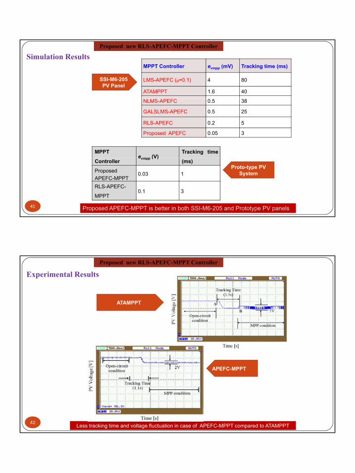
MPPT Controller evmpp (mV) Tracking time (ms)
LMS-APEFC (µ=0.1) 4 80
ATAMPPT 1.6 40
SSI-M6-205 PV Panel
Simulation Results Proposed new RLS-APEFC-MPPT Controller
NLMS-APEFC 0.5 38
GALSLMS-APEFC 0.5 25
RLS-APEFC 0.2 5
Proposed APEFC 0.05 3
MPPTevmpp (V)
Tracking time
Proposed APEFC-MPPT is better in both SSI-M6-205 and Prototype PV panels
Controllerevmpp (V)
(ms)
ProposedAPEFC-MPPT
0.03 1
RLS-APEFC-
MPPT0.1 3
Proto-type PV System
41
ATAMPPT
Experimental Results Proposed new RLS-APEFC-MPPT Controller
APEFC-MPPT
Less tracking time and voltage fluctuation in case of APEFC-MPPT compared to ATAMPPT42

8/29/2014
22
This Chapter proposed a new RLS-APEFC-MPPT controller.
The RLS-APEFC-MPPT has variable forgetting factor.
This proposed MPPT is designed with an adaptive PID-controllerh it t t d b d ti di ti filt
Summary and Contribution
where its parameter are tuned by an adaptive predictive filter
It possesses both faster response and lesser steady-state error thanthat of LMS-APEFC, NLMS-APEFC, GALSLMS-APEFC basedMPPTs and ATAMPPT.
The effectiveness and accuracy of the proposed APEFC techniquehave been verified through simulation and experimental studies
This proposed APEFC MPPT is found to be computationally lesscomplex, and effective in tracking MPP of a PV system.
43
(d) Double Integral Sliding Mode MPPT and Adaptive Double Integral Sliding Mode
MPPT• The RLS-APEFC MPPT is computationally complex with still high steady-state error and chattering in PV voltage.
• By using double integral sliding mode controller (DISMC), a DC/DC converter, it exhibits fast dynamic response, less steady-
state error and reduced chattering in PV voltage.
• Therefore two new MPPTs are developed exploiting the concept of DISMC for a stand-alone PV system such as DISMC-
MPPT and adaptive DISMC-MPPT. These MPPTs are designed in such a way that there is guaranteed stability achieved.
• In literature, two distinct sliding surfaces have been used namely sliding surface 1 (SS1) and sliding surface 2 (SS2). DISMC
with SS1 has less number of components and control variables but has higher chattering in PV voltage whereas DISMC with
SS1 has less chattering and fast tracking but has more number of control variables hence costly and complex.SS1 has less chattering and fast tracking but has more number of control variables hence costly and complex.
• Therefore, a new sliding surface is selected and used to design two DISMC-MPPTs. In the proposed DISMC-MPPT, sliding
surface is assumed fixed whilst in the proposed adaptive DISMC-MPPT; sliding surface is updated with changing weather
conditions.
8/29/2014
23
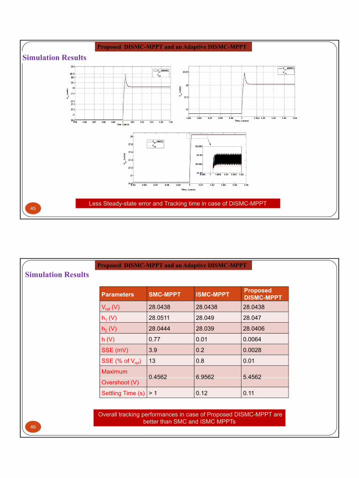
Simulation Results Proposed DISMC-MPPT and an Adaptive DISMC-MPPT
Less Steady-state error and Tracking time in case of DISMC-MPPT45
Parameters SMC-MPPT ISMC-MPPT ProposedDISMC-MPPT
Vref (V) 28.0438 28.0438 28.0438
h (V) 28 0511 28 049 28 047
Simulation Results Proposed DISMC-MPPT and an Adaptive DISMC-MPPT
h1 (V) 28.0511 28.049 28.047
h2 (V) 28.0444 28.039 28.0406
h (V) 0.77 0.01 0.0064
SSE (mV) 3.9 0.2 0.0028
SSE (% of Vref) 13 0.8 0.01
Maximum 0 4562 6 9562 5 4562
Overshoot (V)0.4562 6.9562 5.4562
Settling Time (s) > 1 0.12 0.11
46
Overall tracking performances in case of Proposed DISMC-MPPT are better than SMC and ISMC MPPTs

8/29/2014
24
DISMC-MPPT ISMC-MPPT
Simulation Results Proposed DISMC-MPPT and an Adaptive DISMC-MPPT
Proposed DISMC-MPPT has less chattering
SMC-MPPT
47
radi
ance
s [W
/m2 ] i
ii
iii
Simulation Results Proposed DISMC-MPPT and an Adaptive DISMC-MPPT
Sola
r Irr
Time[s]
i: 1000W/m2, ii: 700W/m2
and iii: 500W/m2
Proposed DISMC-MPPT is better than SMC and ISMC MPPTs48

8/29/2014
25
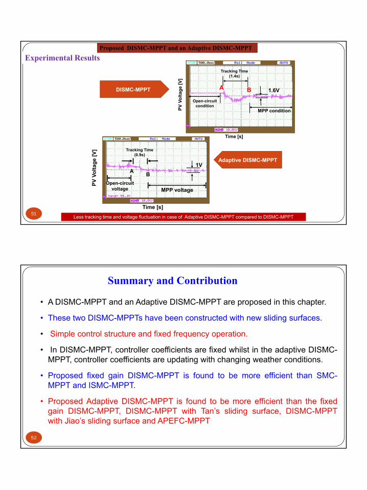
Experimental Results Proposed DISMC-MPPT and an Adaptive DISMC-MPPT
DISMC-MPPT
Although tracking time is higher but less voltage fluctuation in case of DISMC-MPPT compared to APEFC-MPPT
49
Controller
Properties
Tan’s
DISMC-
MPPT
Jiao’s
DISMC-
MPPT
Proposed
DISMC-
MPPT
Proposed
Adaptive
DISMC-
MPPT
Number of current sensors Three Two Two Two
Simulation Results Proposed DISMC-MPPT and an Adaptive DISMC-MPPT
Sliding surface parameters Fixed Fixed Fixed Adaptive
Complexity More Less Less Less
Control VariablesVpv,Vdc,
ipv, iL& iC1
Vpv,Vdc,
ipv, & iC1
Vpv,Vdc,
ipv, & iC1
Vpv,Vdc,
ipv, & iC1Cost more less less less
Reaching time 22 ms < 5ms 110 ms < 5 ms
Settling-time 22 ms > 25ms 5 ms 2.5 ms
Chattering 1.43V 9.3V 28mV 12.5mV
SSE 0.26 V 0.59 V 0.01 V 0.002 VSettling-time during step-change in input 2.5ms 20ms 2ms 1.2ms
Maximum overshoot duringstep-change in input 0.5 volts 4 V 5.4562 V 1 V
50 Overall MPPT property case of Proposed DISMC-MPPT is better
8/29/2014
26
DISMC-MPPT
Volta
ge [V
]
Tracking Time(1.4s)
Open-circuit
1.6VA B
Experimental Results Proposed DISMC-MPPT and an Adaptive DISMC-MPPT
Adaptive DISMC-MPPTge [V
] Tracking Time(0.9s)
1V
PV V Open circuit
conditionMPP condition
Time [s]
Less tracking time and voltage fluctuation in case of Adaptive DISMC-MPPT compared to DISMC-MPPT
PV V
olta
g
MPP voltageOpen-circuit
voltage
Time [s]
1VA B
51
• A DISMC-MPPT and an Adaptive DISMC-MPPT are proposed in this chapter.
• These two DISMC-MPPTs have been constructed with new sliding surfaces.
Summary and Contribution
• Simple control structure and fixed frequency operation.
• In DISMC-MPPT, controller coefficients are fixed whilst in the adaptive DISMC-MPPT, controller coefficients are updating with changing weather conditions.
• Proposed fixed gain DISMC-MPPT is found to be more efficient than SMC-MPPT and ISMC-MPPT.MPPT and ISMC MPPT.
• Proposed Adaptive DISMC-MPPT is found to be more efficient than the fixedgain DISMC-MPPT, DISMC-MPPT with Tan’s sliding surface, DISMC-MPPTwith Jiao’s sliding surface and APEFC-MPPT
52

8/29/2014
27
(e) Self-tuned IPID-controller based MPPTThe DISMC-MPPT with adaptive sliding surface yields better tracking results than that of P&O-MPPT, INC-MPPT,
APO-MPPT, ATAMPPT and APEFC-MPPT with less voltage and current fluctuations, less tracking error and less
tracking time but, the performance of adaptive DISMC-MPPT is dependent on the selection of its sliding surface.
Therefore, there is need of designing a new MPPT using a black-box model of PV system that is identified on-lineTherefore, there is need of designing a new MPPT using a black box model of PV system that is identified on line
considering error in measurement (disturbances).
Hence, a self-tuning MPPT with IPID-controller and RLS identifier for a PV system is proposed. In this self-tuned
MPPT, tracking of MPP is done in a single step by taking as cost function. This MPPT uses incremental PID-
controller.
pv
pv
dpdv
Closely matching
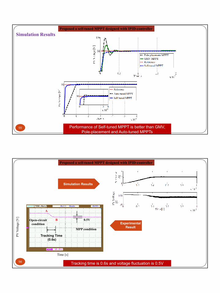
Simulation Results Proposed a self-tuned MPPT designed with IPID-controller
.
54 PV curve with RLS-estimated parameters of PV system matching closely to actual curve
Less estimation error
8/29/2014
28
Simulation Results Proposed a self-tuned MPPT designed with IPID-controller
55 Performance of Self-tuned MPPT is better than GMV, Pole-placement and Auto-tuned MPPTs
Simulation Results
Proposed a self-tuned MPPT designed with IPID-controller
0.5V
Volta
ge [V
]
MPP condition
Open-circuit condition
A
BExperimental
Result
56
Time [s]
PV V
Tracking Time(0.6s)
Tracking time is 0.6s and voltage fluctuation is 0.5V
8/29/2014
29
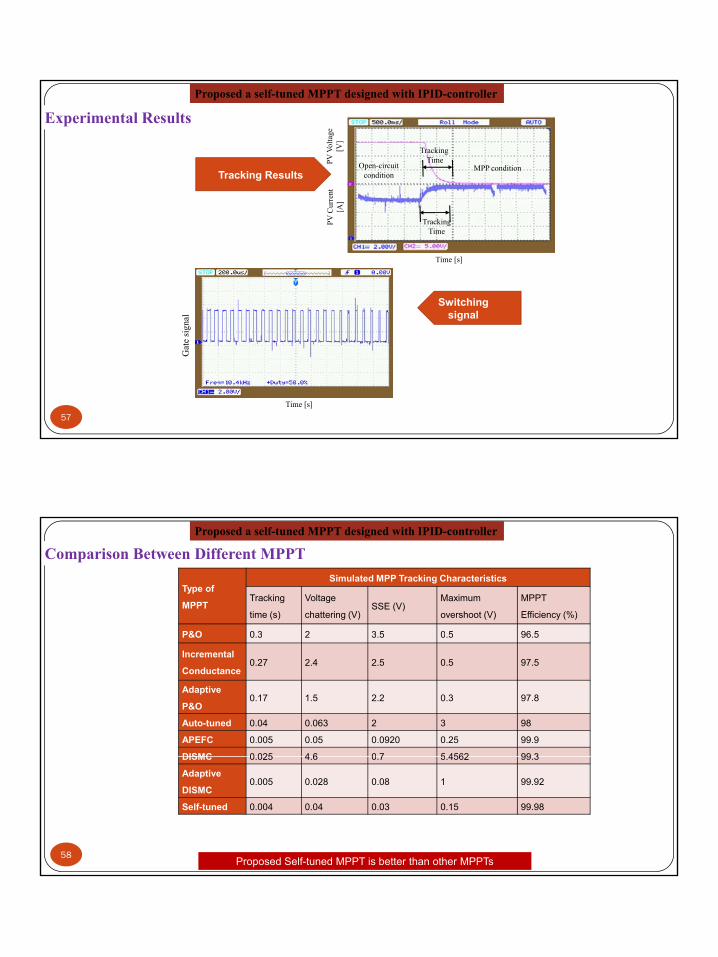
Tracking Results
PV V
olta
ge[V
]re
nt
TrackingTime
MPP conditionOpen-circuit condition
Experimental Results Proposed a self-tuned MPPT designed with IPID-controller
Switching signal
PV C
urr
[A]
Tracking Time
Time [s]
al g
57
Gat
e si
gna
Time [s]
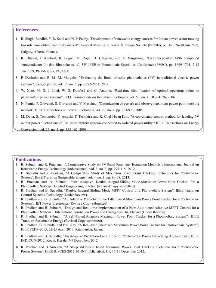
Type of
MPPT
Simulated MPP Tracking Characteristics
Tracking
time (s)
Voltage
chattering (V)SSE (V)
Maximum
overshoot (V)
MPPT
Efficiency (%)
P&O 0.3 2 3.5 0.5 96.5
Comparison Between Different MPPT Proposed a self-tuned MPPT designed with IPID-controller
P&O 0.3 2 3.5 0.5 96.5
Incremental
Conductance0.27 2.4 2.5 0.5 97.5
Adaptive
P&O0.17 1.5 2.2 0.3 97.8
Auto-tuned 0.04 0.063 2 3 98
APEFC 0.005 0.05 0.0920 0.25 99.9
DISMC 0 025 4 6 0 7 5 4562 99 3
Proposed Self-tuned MPPT is better than other MPPTs58
DISMC 0.025 4.6 0.7 5.4562 99.3
Adaptive
DISMC0.005 0.028 0.08 1 99.92
Self-tuned 0.004 0.04 0.03 0.15 99.98

8/29/2014
30
Type of MPPT
Experimental MPP Tracking
Characteristics
Tracking time Voltage chattering
Comparison Between Different MPPT Proposed a self-tuned MPPT designed with IPID-controller
(s) (V)
P&O 0.9 8
Auto-tuned 0.8 5
APEFC 0.7 3
DISMC 0.76 2.5
Adaptive DISMC 0.45 2
S lf t d 0 26 1
Proposed Self-tuned MPPT is better than other MPPTs59
Self-tuned 0.26 1
This chapter proposed a self-tuned MPPT designed with IPID-controller.
For designing this MPPT, PV system is considered as an ARX model. P t f thi ARX d l id tifi d i RLS l ith
Summary and Contribution
Parameters of this ARX model are identified using RLS algorithm.
With simulation and experimental studies, it is found that this MPPT is able to provide less fluctuation in PV voltage.
It has also has less steady state tracking error SSE.
Its MPP tracking time is very less. Further, maximum overshoot during the transient period of MPP tracking is lessduring the transient period of MPP tracking is less.
60
8/29/2014
31
References
1. R. Singh, Randhir, Y. R. Sood and N. P. Padhy, "Development of renewable energy sources for Indian power sector moving
towards competitive electricity market", General Meeting in Power & Energy Society (PES'09), pp. 1-6, 26-30 Jun 2009,
Calgary, Alberta, Canada.
2. R. Dhakal, J. Kofford, B. Logue, M. Ropp, D. Galipeau, and Y. Xingzhong, "Electrodeposited AlSb compoundg pp p g g p p
semiconductor for thin film solar cells", 34th IEEE in Photovoltaic Specialists Conference (PVSC), pp. 1699-1701, 7-12
Jun 2009, Philadelphia, PA, USA.
3. P. Denholm and R. M. M. Margolis, "Evaluating the limits of solar photovoltaics (PV) in traditional electric power
systems", Energy policy, vol. 35, no. 5, pp. 2852-2861, 2007.
4. W. Xiao, M. G. J. Lind, W. G. Dunford and C. Antoine, "Real-time identification of optimal operating points in
h t lt i t " IEEE T ti I d t i l El t i l 53 4 1017 1026 2006photovoltaic power systems", IEEE Transactions on Industrial Electronics, vol. 53, no. 4, 1017-1026, 2006.
5. N. Femia, P. Giovanni, S. Giovanni and V. Massimo, "Optimization of perturb and observe maximum power point tracking
method", IEEE Transactions on Power Electronics, vol. 20, no. 4, pp. 963-973, 2005.
6. M. Datta, S. Tomonobu, Y. Atsushi, F. Toshihisa and K. Chul-Hwan Kim, "A coordinated control method for leveling PV
output power fluctuations of PV–diesel hybrid systems connected to isolated power utility," IEEE Transactions on Energy
Conversion, vol. 24, no. 1, pp. 153-162, 2009.
Publications1. B. Subudhi and R. Pradhan, “A Comparative Study on PV Panel Parameter Extraction Methods”, International Journal on
Renewable Energy Technology (Inderscience), vol. 3, no. 3, pp. 295-315, 2012.2. B. Subudhi and R. Pradhan, “A Comparative Study of Maximum Power Point Tracking Techniques for Photovoltaic
System”, IEEE Trans. on Sustainable Energy, vol. 4, no. 1, pp. 89-98, 2013.3. R. Pradhan and B. Subudhi, “An Adaptive Double-Integral-Sliding-Mode-Maximum-Power-Point-Tracker for a
Photovoltaic System”, Control Engineering Practice (Revised Copy submitted).4. R. Pradhan and B. Subudhi, “Double Integral Sliding Mode MPPT Control of a Photovoltaic System”, IEEE Trans. on, g g y ,
Control Systems Technology (Under Review).5. R. Pradhan and B. Subudhi, “An Adaptive Predictive Error Filter based Maximum Power Point Tracker for a Photovoltaic
System”, IET Power Electronics (Revised Copy submitted).6. R. Pradhan and B. Subudhi, “Design and Real-time Implementation of a New Auto-tuned Adaptive MPPT Control for a
Photovoltaic System”, International journal on Power and Energy System, Elsivier (Under Review).7. R. Pradhan and B. Subudhi, “A Self-Tuned Adaptive Maximum Power Point Tracker for a Photovoltaic System”, IEEE
Trans. on Sustainable Energy (Revised Copy submitted).8. R. Pradhan, B. Subudhi and P.K. Ray, “A Real-time linearized Maximum Power Point Tracker for Photovoltaic System”,
IEEE PEDS-2013, 22-25 April 2013, Kitakyushu, Japan.
9. R. Pradhan and B. Subudhi, “An Adaptive Prediction Error Filter for Photovoltaic Power Harvesting Applications”, IEEEINDICON-2012, Kochi, Kerala, 7-9 December, 2012.
10. R. Pradhan and B. Subudhi, “A Steepest-Descent based Maximum Power Point Tracking Technique for a PhotovoltaicPower System”, IEEE ICPCES-2012, MNNIT, Allahabad, UP, 17-19 December 2012.
8/29/2014
32
11. R. Pradhan and B. Subudhi, “A New Digital Double Integral Sliding Mode Maximum Power Point Tracker for PhotovoltaicPower Generation Application”, ICSET-2012, Kathmandu, Nepal, 24-27 September 2012.
12. B. Subudhi and R. Pradhan, “Characteristics Evaluation and Parameter Extraction of a Solar Array Based on ExperimentalAnalysis”, IEEE PEDS-2011, Singapore 5-8 December 2011.
13. B. Subudhi and R. Pradhan, “A Comparative Study on Solar Parameter Extraction Methods”, NSC-2010, Surathkal,Karnataka, 10-12 December, 2010.
14. R. Pradhan, B. Subudhi and P.K. Ray, “A Real-time linearized Maximum Power Point Tracker for Photovoltaic System”,IEEE PEDS-2013, 22-25 April 2013, Kitakyushu, Japan.
15. R. Pradhan and B. Subudhi, “An Adaptive Prediction Error Filter for Photovoltaic Power Harvesting Applications”, IEEEINDICON-2012, Kochi, Kerala, 7-9 December, 2012.
16. R. Pradhan and B. Subudhi, “A Steepest-Descent based Maximum Power Point Tracking Technique for a PhotovoltaicPower System”, IEEE ICPCES-2012, MNNIT, Allahabad, UP, 17-19 December 2012.
17. R. Pradhan and B. Subudhi, “A New Digital Double Integral Sliding Mode Maximum Power Point Tracker for Photovoltaic17. R. Pradhan and B. Subudhi, A New Digital Double Integral Sliding Mode Maximum Power Point Tracker for PhotovoltaicPower Generation Application”, ICSET-2012, Kathmandu, Nepal, 24-27 September 2012.
18. B. Subudhi and R. Pradhan, “Characteristics Evaluation and Parameter Extraction of a Solar Array Based on ExperimentalAnalysis”, IEEE PEDS-2011, Singapore 5-8 December 2011.
19. B. Subudhi and R. Pradhan, “A Comparative Study on Solar Parameter Extraction Methods”, NSC-2010, Surathkal,Karnataka, 10-12 December, 2010.
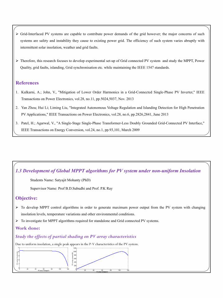
1.2 Robust Control of Grid Interface PV SystemStudents Name: Om Prakash Pahari (PhD)Supervisor Name: Prof B. Subudhi
ObjectiveTo study and investigate PV system Grid connection issues.
To develop intelligent MPPT based on the insolation variation or weather conditions.
To investigate on Power Quality/active and reactive power control of a grid connected PV system.
8/29/2014
33
Grid-Interfaced PV systems are capable to contribute power demands of the grid however; the major concerns of such
systems are safety and instability they cause to existing power grid. The efficiency of such system varies abruptly with
intermittent solar insolation, weather and grid faults.
Therefore, this research focuses to develop experimental set-up of Grid connected PV system and study the MPPT, Power
References
1. Kulkarni, A.; John, V., "Mitigation of Lower Order Harmonics in a Grid-Connected Single-Phase PV Inverter," IEEE
Transactions on Power Electronics vol 28 no 11 pp 5024 5037 Nov 2013
, p p p y y ,
Quality, grid faults, islanding, Grid synchronisation etc. while maintaining the IEEE 1547 standards.
Transactions on Power Electronics, vol.28, no.11, pp.5024,5037, Nov. 2013
2. Yan Zhou; Hui Li; Liming Liu, "Integrated Autonomous Voltage Regulation and Islanding Detection for High Penetration
PV Applications," IEEE Transactions on Power Electronics, vol.28, no.6, pp.2826,2841, June 2013
3. Patel, H.; Agarwal, V., "A Single-Stage Single-Phase Transformer-Less Doubly Grounded Grid-Connected PV Interface,"
IEEE Transactions on Energy Conversion, vol.24, no.1, pp.93,101, March 2009
1.3 Development of Global MPPT algorithms for PV system under non-uniform Insolation
Students Name: Satyajit Mohanty (PhD)
Supervisor Name: Prof B.D.Subudhi and Prof. P.K Ray
Objective:Objective:
To develop MPPT control algorithms in order to generate maximum power output from the PV system with changing
insolation levels, temperature variations and other environmental conditions.
To investigate for MPPT algorithms required for standalone and Grid connected PV systems.
Work done:
St d th ff t f ti l h di PV h t i tiStudy the effects of partial shading on PV array characteristics
Due to uniform insolation, a single peak appears in the P-V characteristics of the PV system.
0 20 40 60 80 100 1206
7
8
9
10
11
PV array Volltage(V)
PV
arr
ay C
urre
nt(A
)
0 20 40 60 80 100 1200
200
400
600
800
1000
1200
PV array voltage(V)
PV a
rray
pow
er(W
)

8/29/2014
34
0 20 40 60 80 100 12010
12
14
16
18
20
22
Cur
rent
of P
V a
rray
0 20 40 60 80 100 1200
200
400
600
800
1000
1200
1400
1600
Pow
er fr
om P
V a
rray(
W)
Output characteristics of PV array with non-uniform insolation (a) I-V characteristics (b)P-V characteristics
0 20 40 60 80 100 120Voltage of PV array
0 20 40 60 80 100 120Voltage across PV array(V)
Due to variation in solar insolation and partial shading conditions, a no of multiple peaks appear in the P‐V characteristics ofthe PV system
150
200
250
300
rent
(mA)
100
150
200
250
rren
t(mA
)
V‐I curve obtained from solar simulatorusing frosted glass and 50% shading
0.1 0.15 0.2 0.25 0.3 0.35 0.4 0.45 0.5 0.55 0.60
50
100
Voltage(V)
Cur
0.05 0.1 0.15 0.2 0.25 0.3 0.35 0.4 0.45 0.5 0.550
50
100
Voltage(V)
Cur
References
[1] Kun Ding, X. Bian, H.H Liu, and Tao Peng, “A MATLAB Simulink Based PV module model and its application under
conditions of non-uniform irradiance”, IEEE Trans. on Energy Conversion, vol. 27, no.4, 2012, pp. 864-871.
[2] Young-Hyok Ji, Doo-Yong Jung, Jun-Gu Kim, Jae-Hyung Kim, Tae-Won Lee and Chung-Yuen Won, “A Real Maximum Power
Point Tracking Method for Mismatching Compensation in PV Array Under Partially Shaded Conditions”, IEEE Trans. on Power
Electronics, vol. 26, no. 4, Apr. 2011, pp. 1001-1009.
[3] Hiren Patel and Vivek Agarwal, “Maximum Power Point Tracking Scheme for PV Systems Operating Under Partially Shaded
Conditions”, IEEE Trans. on Industrial Electronics, vol. 55, no. 4, Apr. 2008, pp.302-310.
[4] Hiren Patel and Vivek Agarwal “MATLAB-Based Modeling to Study the Effects of Partial Shading on PV Array[4] Hiren Patel and Vivek Agarwal, MATLAB Based Modeling to Study the Effects of Partial Shading on PV Array
Characteristics”, IEEE Trans. on Energy Conversion, vol. 23, no. 1, Mar. 2008, pp.302-310.
8/29/2014
35
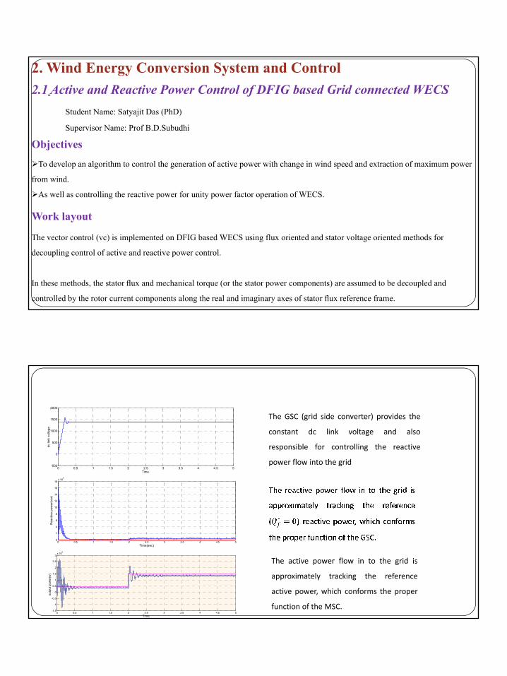
2. Wind Energy Conversion System and Control2.1 Active and Reactive Power Control of DFIG based Grid connected WECS
Student Name: Satyajit Das (PhD)
Supervisor Name: Prof B.D.Subudhi
Obj tiObjectives
To develop an algorithm to control the generation of active power with change in wind speed and extraction of maximum power
from wind.
As well as controlling the reactive power for unity power factor operation of WECS.
Work layout
The vector control (vc) is implemented on DFIG based WECS using flux oriented and stator voltage oriented methods for
decoupling control of active and reactive power control.
In these methods, the stator flux and mechanical torque (or the stator power components) are assumed to be decoupled and
controlled by the rotor current components along the real and imaginary axes of stator flux reference frame.
500
1000
1500
2000
dc li
nk v
olta
ge
The GSC (grid side converter) provides the
constant dc link voltage and also
responsible for controlling the reactive
0 0.5 1 1.5 2 2.5 3 3.5 4 4.5 5-500
0
Time
p g
power flow into the grid
2
4
6
8
10
12
14
16
18x 10
6
Rea
ctiv
e po
wer
(var
)
0 0.5 1 1.5 2 2.5 3 3.5 4 4.5 5-1.5
-1
-0.5
0
0.5
1
1.5
2
2.5
3x 10
6
Time
outp
ut p
ower
(w)
0 0.5 1 1.5 2 2.5 3 3.5 4 4.5 50
Time(sec)
The active power flow in to the grid is
approximately tracking the reference
active power, which conforms the proper
function of the MSC.

8/29/2014
36
Future Work
1. To investigate on power quality, active and reactive power control of a grid connected WECS by implementing different
control technique such as Direct Torque Control (DTC), Direct Power Control (DPC) using MATLAB/ Simulink.
2. To develop an experimental set-up of Grid connected WECS.
3 To design new strategy for controlling active and reactive power for the Wind Energy Conversion System and3. To design new strategy for controlling active and reactive power for the Wind Energy Conversion System and
implementation of the same in real time experimental set up.
References[1] S. Muller, M. Deicke, and R. W. De Doncker, “Doubly fed induction generator systems for wind turbines,”IEEE Ind. Appl. Mag., vol. 8, no. 3,pp. 26–33, May/Jun. 2002.
[2] J. Hu, Y. He, L. Xu, and B. W. Williams, “Improved control of DFIG systems during network unbalance using PI-R current regulators ” IEEE Trans Ind Electron vol 56 no 2 pp 439 451 Feb 2009regulators, IEEE Trans. Ind. Electron., vol. 56, no. 2, pp. 439–451, Feb. 2009.
[3] R. Pena, J. C. Clare, and G. M. Asher, “Doubly fed induction generator using back-to-back PWM converter and is application to variable-speed wind–energy generation,” Proc. IEE B Electr. Power Appl., vol. 143,no. 3, pp. 231–241, May 1996.
[4] G. S. Buja and M. P. Kazmierkowski, “Direct torque control of PWM inverter-fed ac motors-a survey,” IEEE Trans. Ind. Electron., vol. 51,no. 4, pp. 744–575, Aug. 2004.
2.2 MPPT (Maximum Power point Tracking)Students Name: O.P.Suresh (Ph.D), Suchismita Acharya(M.Tech)
Supervisor Name: Prof B.D.Subudhi
ObjectiveDevelopment of new MPPT technique for DFIG based Grid connected WECS
Power coefficient Vs TSR Power coefficient vs tip speed ratio at zero pitch angle
Power coefficient vs tip speed ratio at different pitch angle

8/29/2014
37
References
[1] T. Thiringer and J. Lindres, “Control by variable rotor speed of a fixed-pitch wind turbine operating in a wide speed
range,” IEEE Trans. Energy Conversion, vol. 8, pp. 520–526, Sept. 1993.
[2] I. Eskandarzadeh and H. Ince, “Modeling and output power optimization of a wind turbine driven doubly output
induction generator,” Proc. IEEE – Electr. Power Applicat, vol.141, no.2, pp. 33–38, March.1994.
Publications
[3] Fengxiang Wang, Chengwu Lin, and Longya Xu “A chopping and doubly-fed adjustable speed system without bi-
dirctional converter,” IEEE Trans. Ind. Applicat., vol. 20, pp. 2393–2397, October 2002.
[4] Yifan Tang, and Longya Xu “A flexible active and reactive power control strategy for a variable speed constant frequency
generating system,” IEEE Trans. Power Electronic, vol. 10, pp. 472–478, July 1995.
1. O.P.Suresh and B.Subudhi, Sliding mode approach to torque and pitch control for an wind energy system using FPGA,
India Conference (INDICON), 2012 Annual IEEE, 2012 , Kochi, 7-10 Dec. 2012
2. O.P.Suresh and B.Subudhi, Sliding mode approach to torque and pitch control for an wind energy system using FPGA,
India Conference (INDICON), 2012 Annual IEEE, 2012 , Kochi, 7-10 Dec. 2012
Objectives and work layout
I t ti f i d i i ti t bl
2.3 Wind Speed Estimation with Wavelet Neural NetworksStudent Name: Prangya Parimita Pradhan (M.Tech)
Supervisor Name: Prof B.D.Subudhi
Integration of wind energy in existing power system causes problemsPower Quality,StabilityPower Dispatching
Control methodEffective wind speed/ power forecasting.
WORK LAYOUTThe available wind speed sample (2982) collected from National Renewable Energy Laboratory (NREL)[1] has been
decomposed up to 5th level with Maximum Overlap Discrete Wavelet transform(MODWT).
Each decomposed sample forecasted individually with different neural networks.
Finally each level forecasted outputs are added to get the wind speed forecast up to 30 hour ahead.

8/29/2014
38
1.Wind speed estimation with feed-forward multilayer neural network:
This neural network consists of three layer as input layer, hidden layer and output layer.
Si id l f i h b l d i i f i i h hidd l d fi d
Wind Speed Forecast
Sigmoidal function has been selected as activation function in the hidden layer, defined as
Where x is the input to the hidden layer that is the decomposed wind speed samples (detail coefficients of each
level from 1st to 5th level and approximate coefficients of 5th level) patterns.
2. Wind speed estimation with wavelet neural network:
Feed-forward wavelet neural network also consists of three layer same as feed-forward multilayer neural
k h i i l hidd l d h l
11
( ) xexφ −+=(.)φ
network that is input layer, hidden layer and the output layer.
Instead of sigmoidal function Mexican hat has been selected as mother wavelet that is the activation
function in the wavelet layer ( hidden layer), defined as
20.5(( ) / )2, ( ) (1 ( ) ) iu b ai
a b iu bu e
aψ − −−
= − ×
(.)ψ
1
2
3
4
spee
d(m
/s),e
rror
predictedactualerror
Results of wind speed estimation with neural network
Mean absolute error(MAE)=10.14%
0 10 20 30 40 50 60 70 80 90 100-1
0
time(hour)
win
d
wind speed forecast of 100 successive hour ahead forecasting with multilayer feed-forward neural network
3
4
),err
or
predictedactualerror
0 10 20 30 40 50 60 70 80 90 100-1
0
1
2
time(hour)
win
d sp
eed(
m/s
)
wind speed forecast of 100 successive hour ahead forecasting with feed-forward wavelet neural network
Mean absolute error(MAE)=1.53%

8/29/2014
39
Future Work
Comparative studies with other methods for wind speed forecasting.
Wind power forecast will be carried out by recursively taking the previous wind power forecast values along with the wind
speed forecast obtained from neural network.
References[1]National Renewable Energy Laboratory[Online]. Available: http://www.nrel.gov/wind/integrationdatasets/eastern/data.html.
[2] “Indian Wind Energy and Economy,” Indianwindpower.com. Retrieved 2009-09-17.
[3] Shu Fan, James R. Liao, Ryuichi Yokoyama, Luonan Chen and Wei-Jen Lee, “Forecasting the Wind Generation Using a Two-
To design a control strategy to overcome the limitation of existing approaches .
Stage Network Based on Meteorological Information,” IEEE Trans. Energy Convers., vol. 24, no. 2, June 2009.
[4] Kanna Bhaskar and S. N. Singh, “AWNN-Assisted wind power forecasting using feed-forward neural network, “IEEE
Transactions on sustainable energy, vol.3,no. 2,april 2012.
[5] Xinghuo Yu, M. OnderEfe, and OkyayKaynak, “A General Back propagation Algorithm for Feed forward Neural Networks
Learning,” IEEE Transactions on neural networks, vol.13, no.1, january2002.
2.4 WECS Grid Integration IssuesStudents Name: Snehaprava Swain (Ph.D)
Supervisor Name: Prof P.K. Ray
Objectives1)power system security and stability analysis
2) Power quality improvement
Work DoneMaintaining grid reliability by precise synchronization of voltage and current:
Here an ac system of 60amp, 120v is analysed before synchronisation as well as after synchronization. This system analysis is analogous to the WTCS analysis inter linked with the power system grid.
Case‐I :(Before Synchronization)Case‐II:(After Synchronization)
current is slightly out of phase with the voltage.current is in phase with the voltage.

8/29/2014
40
Future ScopeReliability assessment of the integrated system by calculating different reliability indices.
References
[1].M. Moeini-Aghtaie , A. Abbaspour , and M. Fotuhi-Firuzabad, “Incorporating large-scale distant wind farms in
probabilistic transmission expansion planning—Part I: Theory and algorithm ” IEEE Trans Power Syst vol 27 no 3 ppprobabilistic transmission expansion planning Part I: Theory and algorithm, IEEE Trans. Power Syst., vol. 27, no. 3, pp.
1585–1593, Aug. 2012.
[2]T. Ackermann, Wind Power in Power Systems. Hoboken, NJ, USA: Wiley, 2008.
[3] R. Karki and R. Billinton, “Reliability/cost implications of PV and wind energy utilization in small isolated power
systems,” IEEE Trans. Energy Convers., vol. 16, no. 4, pp. 368–373, Dec. 2001.
[4] Y. Gao and R. Billinton, “Adequacy assessment of generating systems containing wind power considering wind speed
correlation,” IET Renew. Power Generat., vol. 3, no. 2, pp. 217–226, Jun. 2009.
[5] P. Hu, R. Karki, and R. Billinton, “Reliability evaluation of generating systems containing wind power and energy
storage,” IET Generat., Trans., Distrib., vol. 3, no. 8, pp. 783–791, Aug. 2009
3.Distributed Power Generation
3.1 Development of Control Techniques in Shunt Active Power FilterStudents Name: Rakhee Panigrahi(Ph.D)
Objectives
To develop different control strategies in Shunt Active Power Filter (SAPF) to provide an adequate dynamic behavior under
consideration of grid perturbations
Supervisor Name: Prof B Subudhi, Prof P.C. Panda
Control strategies :
Hysteresis controller (HC) and Dead beat (DB) Controller
Sliding Mode Current (SMC) controller
Model Predictive based current controller (MPC)

8/29/2014
41
Functional Structure of SAPF Hysteresis and
Dead beat Current Controller:
sV
sV Li ci DCV
sL sR
cR
cLci
si Li
DCV
DCV
'DCV
sV
Lisi
*refi
si ci1Ci
2Ci
1PV
Control Block Diagram using Hysteresis(HC)
Control Block Diagram using Dead Beat
control (DBC) method
Li
DCV +−I
DCVI
++
ˆ I
Ci
ˆ II
Ci
Ci + −Ci
ei
1PV
I
CV CV+ −
SV
LV
Ci
SV
Simulation Results
100
150
200
250
300300
Vol
tage
(V)
0
30
Am
plitu
de(A
)
0 0.02 0.04 0.060
50
Time(s)0 0.05 0.1 0.15 0.2 0.25 0.3-30
Time(s)
A
150
200
250
300300
age(
V)
0
30
litud
e(A
)
(a)
0 0.02 0.04 0.060
50
100
Time(s)
Vol
ta
0 0.05 0.1 0.15 0.2 0.25 0.3-30Time(s)
Am
pl
(a) Capacitor voltage and compensating waveforms in DB method (b) Capacitor voltage and compensating waveforms in HC method
(b)

8/29/2014
42
Sliding Mode Controller
Labciav
SVLOAD
bvcv
sabci
fL
R
sL sR
∗
dcvfR
⇑
⇑
−+
PI CONTROLLERdcv∗
i
Fabci
PWM
SLIDING MODECONTROLLERsabci
sabci∗ smi
abcUavbvcv
UNIT VECTOR GENERATIONUSING RECKF
FUNDAMENTAL ESTIMATIONAND
PROPOSED
MULTIPLIER
REFERENCE GENERATION
Structure of SMC based SAPF
Simulation Results
50
0
50
100
150
(V) a
nd C
urre
nt(A
)
Source CurrentSource Voltage
KF
-50
0
50
100
150
age(
V) a
nd C
urre
nt(A
)
Source CurrentSource Voltage
EKF
0 0.25 0.5 0.75 1 1.25 1.5 1.75 2 2.25 2.5-150
-100
-50
Time(s)
Vol
tage
(
0 0.25 0.5 0.75 1 1.25 1.5 1.75 2 2.25 2.5
-150
-100
Time(s)
Vol
ta
50
100
150
d C
urre
nt(A
)
Source CurrentSource Voltage
ECKF
50
100
150
Cur
rent
(A)
Source CurrentSource Voltage
RECKF
(a) (b)
0 0.25 0.5 0.75 1 1.25 1.5 1.75 2 2.25 2.5-150
-100
-50
0
Time(s)
Vol
tage
(V) a
nd
0 0.25 0.5 0.75 1 1.25 1.5 1.75 2 2.25 2.5-150
-100
-50
0
Time(s)
Vol
tage
(V) a
nd
Source voltage and source current waveforms in SMC based SAPF for (a) KF, (b) EKF, (c) ECKF, (d) RECKF
(c) (d)
8/29/2014
43
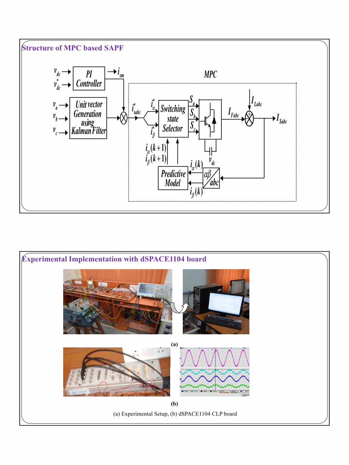
Structure of MPC based SAPF
PIController
dcv smidcv∗
S I
MPC
avbvcv
Unit vectorGeneration
usingKalman Filter
sabci∗ iα∗
iβ∗
Switchingstate
Selector
aSbScS
( 1)i kα +( 1)i k
FabcI +−LabcI
SabcI
dcvαβ
abcPredictive
Model
( )i kα
( )i kβ
( 1)i kβ +
Experimental Implementation with dSPACE1104 board
(a)
(b)
(a) Experimental Setup, (b) dSPACE1104 CLP board

8/29/2014
44
Future Plan1. The Shunt Active power filter applications can be extended to multiple actions such as hybrid filter, STATCOM, unified power
quality conditioner (UPQC).
2. The control strategy of SAPF can be extended in nonlinear framework such as nonlinear H-infinity filtering, nonlinear quadratic
Gaussian controller and the estimation approaches can be extended to Unscented Kalman filter Particle filterGaussian controller and the estimation approaches can be extended to Unscented Kalman filter, Particle filter.
References
[1] J. M. Kanieski, R. Cardoso, and H. A. Grundling, “Kalman filter based control system for power quality conditioning
devices”, IEEE Trans.on Industrial Electron., doi:10.1109/TIE, 2012.
[2] K. H. Kwan, P. L. So, and Y. C. Chu, “An output regulation-based unified power quality conditioner with Kalman filters”,[ ] , , , p g p q y ,
IEEE Trans. on Industrial Electron., vol. 59, pp.4248-4262, Nov. 2012.
[3] M. Rivera, V. Yaramasu, and J. Rodriguez, “Model Predictive current control of two-level four leg inverters-part II:
experimental implementation and validation,” IEEE Trans. Power Electron., vol. 28, no. 7, pp. 3469–3478, Jul. 2013.
[4] N. Gupta, S. P. Singh and R. C. Bansal, “A digital signal processor based performance evaluation of three-phase four-wire
shunt active filter for harmonic elimination, reactive power compensation and balancing of non-linear loads under non-ideal
mains voltages,” Elect. Power Compon. Syst., vol. 40, no. 10, pp. 1119-1148, 2012.
[5] A. Chandra, B. Singh, and B. N. Singh, “An Improved Control Algorithm of Shunt Active Filter for Voltage Regulation,
H i Eli i i P F C i d B l i f N li L d ” IEEE T P El l 15Harmonic Elimination, Power-Factor Correction, and Balancing of Nonlinear Loads,” IEEE Trans. Power Electron., vol. 15,
no. 3, pp. 495–507, May. 2000.
Publications[1] R.Panigrahi, P.C.Panda and B.Subudhi, A Robust Extended Complex Kalman Filter and Sliding Mode Control based Shunt
Active Power Filter, Electric Power Components and Systems, vol.42,no.5,pp.520–532, 2014.
[2] R Panigrahi P C Panda and B Subudhi Comparison of Performances of Hysteresis and Dead Beat Controllers in Active[2] R.Panigrahi, P.C.Panda and B.Subudhi, Comparison of Performances of Hysteresis and Dead Beat Controllers in Active
Power, 3rd IEEE International Conference on Sustainable Energy Technologies, IEEE ICSET 2012, Kathmandu, Nepal, 24-27
Sep 2012.Kathmandu.

8/29/2014
45
[3] R.Panigrahi, P.C.Panda and B.Subudhi, New strategy for generation of reference current in active power filters with
distortion in line voltage, IEEE Conf. Madras, 2012
[4] P.K.Ray and B.Subudhi, Ensemble Kalman Filtering Algorithm applied to Power System Harmonics Estimation, IEEE
Trans. on Instrumentation and Measurement , vol.61, no.12, pp.3216-3224, 2012
[5] B. Subudhi, P. K. Ray and S. Ghosh, “Variable Leaky LMS Algorithm Based Power System Frequency Estimation” IET
S i M t & T h l l 6 i 4 288 297 2012Science, Measurement & Technology, vol.6, issue 4, pp. 288-297, 2012
[6] P.K.Ray and B.Subudhi, BFO optimized RLS algorithm for Power System Harmonics Estimation, Applied Soft
Computing (Elsevier), 12 (2012) 1965–1977
3.2. Development of Real-time Estimation and Filtering Algorithms with Applications to Distributed Generation
Objectives and work layout
Student Name: Aurobinda Bag (PhD)
Supervisor Name: Prof B.D.Subudhi, Prof P.K. Ray
Objectives and work layoutTo develop efficient and robust nonlinear estimation algorithms in nonlinear framework for power system frequency and harmonics estimation of
an AC Micro-grid comprising of two Renewable Energy Sources such as PV and WES.
To utilize the developed estimation algorithms for designing active power filters of the Micro-grid system and to verify the techniques using
MATLAB and OPAL -RT.
To implement the developed estimation and filtering algorithms on the hardware (Microgrid, Active Filter).
WORK LAYOUTThe project intends to analyse and develop advanced filter solutions based on combinations of passive filters and active filters. The use of
passive filters is almost standard for harmonic mitigation; therefore, the primary focus is to develop active filter solutions. For the active
power filters, the power electronic converters already present in the hybrid energy system.

8/29/2014
46
The objective is to have an optimized combination of active and passive filter. At present the harmonic mitigation is mainly
achieved by large passive filters in the wind turbines and at the grid connection substation. In addition to reviewing this
approach, use of active filters either in combination with the existing and/or new passive filters will be investigated.
References
[1] Damoun Ahmadi, Jin Wang,” Online Selective Harmonic Compensation and Power Generation With Distributed Energy Resources”
IEEE Trans. on Power Electronics, Vol. 29, no. 7, pp.3738-3747, July 2014.
[2] Koen J. P. Macken, Koen Vanthournout, Jeroen Van den Keybus, Geert Deconinck, and Ronnie J. M. Belmans,“Distributed Control of
Renewable Generation Units With Integrated Active Filter” IEEE Trans. on Power Electronics, Vol. 19, no. 5, pp.1551-1561, Sep 2004.
[3] R. Chudamani, K. Vasudevan and C.S.Ramalingam “ Real time Estimation of Power System Frequency using nonlinear Least Squares” IEEE Trans. on
Power Delivery, vol. 24, no.3, pp. 1021-1028, 2009.
[4] H. Akagi, A. Nabae and S. Atoh “Control Strategy of Active Power Filters Using Multiple- Voltage Source PWM Converters", IEEE Trans. on Ind.Applicat.
Vol.1, no.3, pp. 460-465, May/June 1986.
Laboratory Development

8/29/2014
47
Laboratory DevelopmentRenewable Power Generation Control LabWind Energy Conversion System(WECS)PV SystemMNRE10 KW PV ModuleSpecification:(A) Wind Energy Control System1. Wind Turbine and Generator
2kW DFIG generator with a PMSM based wind turbine emulator2. Voltage source inverters:
(i) To feed the PMSM(ii) To be connected to the output of DFIG for grid connection
3. Programmable Power Source:(i) dsPIC based PWM Controller(ii) Voltage Source Inverter
4. RTDS (Real Time Simulator)
5. Sensors:
(i) Temperature sensor
(ii) Air speed sensor
(iii) Speed sensor(iii) Speed sensor
3. DC-DC Converter 2kW:
(i) dsPIC Based PWM Converter
(ii) Voltage Source Inverter
(iii) DC to DC Bidirectional buck boost converter for charging the battery
4. Bi-directional Converters:
(i) 4 Nos of high speed IGBT or MOSFET semiconductor devices are to be used
(ii) 4 Nos of isolated high speed driver circuits are used
(iii) 2 Nos of hall effect current tranducers used for sensing the input and output of the converter current
(iv) 2 Nos of hall effect voltage tranducers used for sensing the input and output of the converter voltage
(v) In boost mode input is 100v and output is 300v

8/29/2014
48
(vi) In buck mode input is 300v and output is 100v(vii) Power rating is 200w(viii) dv/dt protection is available for all IGBT (snubber circuit)(ix) dsPIC 4011 digital controller is used for generating the gate signal for IGBT with over load protection
5. VSI inverters:(i)VPE SPARTAN 3A/3A DSP BOARD(ii) Voltage source inverter 2 nos
6. Data acquisitionData acquisition systemFPGA Based high speed data acquisition system with anti-aliasing filter
7. Non-linear load(i)Diode rectifier(1200V, 60A)(ii)3 KW resistive load with 9 selector switch
8. Batterynos. of 12V, 200A per hour battery is connected in sensing to get 100V DC output
9. Wind Energy Emulator(i)Energy Emulator using DC motor coupled with 1kW slip ring induction motor(ii)Dc shunt moor coupled with 1kW slip ring IM with sensor set up.(iii)VPE Spartan 3A/3A DSP Board(iv)Power module for DFIG(v)Shunt active filter
10. Voltage source inverter
Under Process100 Kw PV SystemMNRE Solar Insolation recording setup

8/29/2014
49
Thank You