be1 40q loss of excitation relay
TRANSCRIPT

8/12/2019 BE1 40Q Loss of Excitation Relay
http://slidepdf.com/reader/full/be1-40q-loss-of-excitation-relay 1/45
INSTRUCTION MANUALFOR
LOSS OF EXCITATION RELAY
BE1-40Q
P0050-23
40Q
Publication: 9171500990Revis ion: L 09/07

8/12/2019 BE1 40Q Loss of Excitation Relay
http://slidepdf.com/reader/full/be1-40q-loss-of-excitation-relay 2/45

8/12/2019 BE1 40Q Loss of Excitation Relay
http://slidepdf.com/reader/full/be1-40q-loss-of-excitation-relay 3/45
9171500990 Rev L BE1-40Q Introduct ion i
INTRODUCTIONThis instruction manual provides information about the operation and installation of the BE1-40Q Loss ofExcitation Relay. To accomplish this, the following information is provided:
• General Information and Specifications
• Controls and Indicators
• Functional Description
• Installation• Testing
WARNING!
To avoid personal injury or equipment damage, only qualified personnel shouldperform the procedures in this manual.
NOTE Be sure that the relay is hard-wired to earth ground with no smaller than 12 AWGcopper wire attached to the ground terminal on the rear of the unit case. Whenthe relay is configured in a system with other devices, it is recommended to use aseparate lead to the ground bus from each unit.

8/12/2019 BE1 40Q Loss of Excitation Relay
http://slidepdf.com/reader/full/be1-40q-loss-of-excitation-relay 4/45
ii BE1-40Q Introduct ion 9171500990 Rev L
First Printing: November 1986
Printed in USA
© 1986, 1988-1991, 1994-1995, 1998, 2001, 2007 Basler Electric, Highland Illinois 62249 USA
All Rights Reserved
September 2007
It is not the intention of this manual to cover all details and variations in equipment, nor does this manualprovide data for every possible contingency regarding installation or operation. The availability and designof all features and options are subject to modification without notice. Should further information berequired, contact Basler Electric.
BASLER ELECTRICROUTE 143, BOX 269
HIGHLAND IL 62249 USAhttp: //www.basler.com, [email protected]
PHONE +1 618.654.2341 FAX +1 618.654.2351
CONFIDENTIAL INFORMATION
of Basler Electric, Highland Illinois, USA. It is loaned for confidential use, subjectto return on request, and with the mutual understanding that it will not be used inany manner detrimental to the interest of Basler Electric.

8/12/2019 BE1 40Q Loss of Excitation Relay
http://slidepdf.com/reader/full/be1-40q-loss-of-excitation-relay 5/45
9171500990 Rev L BE1-40Q Introduct ion iii
REVISION HISTORY
The following information provides a historical summary of the changes made to the BE1-40Q instructionmanual (9171500990). Revisions are listed in reverse chronological order.
Manual
Revision and Date Change
L, 09/07 • Added manual part number and revision to footers.• Updated Output Contact ratings in Section 1.
• Updated Power Supply Burden data in Section 1.
• Updated front panel illustrations to show laser graphics.
• Updated Target Indicator description in Section 3.
• Added GOST-R to Section 1, General Information.
• Moved content of Section 7, Manual Change Information to ManualIntroduction.
• Moved content of Section 6, Maintenance to Section 4, Installation.
K, 02/01 • Updated S1 case drawings in Section 4 to the most recent drawings.
J, 10/98 • Corrected Voltage Sensing in Specifications from “Each have a
burden that is less than 0.1 ohm over the” to “Each have a burdenthat is less than 1 VA over the”.
• Deleted 500 Vdc from Resistive Output Circuits.
• Deleted all references to Service Manual.
• Updated Style Number Identification Chart by changing Power SupplyType T from “230 Vac” to “240 Vac”.
• Added new power supply information to Specifications and Section 3starting with “Basler Electric enhanced the power supply design…”
• Changed the format of the manual.
H, 03/95 • Changed Section 1, General Information, Specifications, OutputCircuits and Isolation.
• Added phase rotation sensitivity information to Section 3, FunctionalDescription.
• Changed Section 4, Installation, Dielectric Test, to reflect specificationchanges.
• Corrected Figure 4-1 and changed Figure 5-2, note 2.
• Corrected typographical error in Table 5-4, Reactive Power (Vars), +120.
• Corrected typographical error in Section 6, Maintenance, General.
G, 01/94 • Deleted references to mho characteristic.
• Corrected Figure 4-3 (Sensing Input Test Setup), current sensinginput terminals 8 and 9 were reversed on earlier versions;renumbered equations; updated format; and added new internal
connection diagrams Figures 4-3 through 4-5, added new mountingdiagrams Figures 4-6 through 4-14.
• Added new Section 5, Setting and Testing, moved appropriate datafrom Section 4 into Section 5, and changed Section 5 and 6 toSection 6 and 7.

8/12/2019 BE1 40Q Loss of Excitation Relay
http://slidepdf.com/reader/full/be1-40q-loss-of-excitation-relay 6/45
iv BE1-40Q Introduct ion 9171500990 Rev L
Manual
Revision and Date Change
F, 01/91 • Pages 1-3, 1-5 (Style Chart), 1-7 2-1 (Item H), 4-4 (step 3), 4-7 (Step3): Time delay range is 0.1 to 9.90 seconds, adjustable in incrementsof 0.1 seconds. This was previously unclear or (in some cases)erroneous.
• Page 1-8: RFI specification added.
• Pages 1-6, 5-1: minor editing.
E, 09/90 • Legend of Figure 3-2 corrected.• Page 3-1 (under “Phase Shift”): 68° was 52°.
D, 08/89 • Equations 4.1 through 4.4 put into standard form by removingnegative sign from the angle theta.
C, 06/89 • Figure 3-2 corrected.
• Equations on page 4-8 restated for clarification.
• Arithmetical errors corrected in the example given on page 4-8.
• Table 4-2 corrected.
• Figure 4-3 was reformatted.
• Figure 4-7 revised to clarify installation.
B, 11/88 •
Minor corrections and editing. A, 11/88 • Figure 3-3 added.
• Editing changes made to clarify specifications.
• Two articles added to Section 4, entitled, “Setting the Pickup” (page4-5) and, “Relay Characteristic Verification” page 4-7.
—, 01/86 • Initial release

8/12/2019 BE1 40Q Loss of Excitation Relay
http://slidepdf.com/reader/full/be1-40q-loss-of-excitation-relay 7/45
9171500990 Rev L BE1-40Q Introduction v
CONTENTS
SECTION 1 GENERAL INFORMATION................................................................................................ 1-1PURPOSE........................................................................................................................................... 1-1
APPLICATION .................................................................................................................................... 1-1Capability Curves ......................................................................................................................... 1-1BE1-40Q Operating Characteristics............................................................................................. 1-1Time Delay.................................................................................................................................... 1-1
MODEL AND STYLE NUMBER.......................................................................................................... 1-3Style Number Example................................................................................................................. 1-3
SPECIFICATIONS .............................................................................................................................. 1-4Current Sensing............................................................................................................................ 1-4Current Sensing Burden............................................................................................................... 1-4Voltage Sensing ........................................................................................................................... 1-4Pickup Range ............................................................................................................................... 1-4Pickup Accuracy ........................................................................................................................... 1-4Dropout......................................................................................................................................... 1-4Time Delay Range........................................................................................................................ 1-4Timing Accuracy ........................................................................................................................... 1-4Output Contacts............................................................................................................................ 1-5Power Supply................................................................................................................................ 1-5Target Indicators........................................................................................................................... 1-6
Type Tests.................................................................................................................................... 1-6Physical ........................................................................................................................................ 1-6
Agency Recognition/Certification ................................................................................................. 1-6
SECTION 2 CONTROLS AND INDICATORS ....................................................................................... 2-1INTRODUCTION................................................................................................................................. 2-1
SECTION 3 FUNCTIONAL DESCRIPTION........................................................................................... 3-1INTRODUCTION................................................................................................................................. 3-1VOLTAGE SENSING.......................................................................................................................... 3-1PHASE SHIFT..................................................................................................................................... 3-1CURRENT SENSING ......................................................................................................................... 3-2HI/LOW RANGE SWITCH .................................................................................................................. 3-2
TAP SWITCH...................................................................................................................................... 3-3TRANSDUCER ................................................................................................................................... 3-3COMPARATOR .................................................................................................................................. 3-3TIMING........................................................................................................................ ........................ 3-3OUTPUTS........................................................................................................................................... 3-3PUSH-TO-ENERGIZE OUTPUT PUSHBUTTON .............................................................................. 3-3POWER SUPPLY STATUS OUTPUT................................................................................................ 3-3POWER SUPPLY ............................................................................................................................... 3-3TARGET INDICATORS ...................................................................................................................... 3-4
Internally Operated Targets.......................................................................................................... 3-4Current Operated Targets ............................................................................................................ 3-4
SECTION 4 INSTALLATION.................................................................................................................. 4-1
INTRODUCTION................................................................................................................................. 4-1RELAY OPERATING GUIDELINES AND PRECAUTIONS ............................................................... 4-1MOUNTING......................................................................................................................................... 4-1CONNECTIONS................................................................................................................................ 4-12MAINTENANCE................................................................................................................................ 4-15STORAGE......................................................................................................................................... 4-15
8/12/2019 BE1 40Q Loss of Excitation Relay
http://slidepdf.com/reader/full/be1-40q-loss-of-excitation-relay 8/45
vi BE1-40Q Introduct ion 9171500990 Rev L
SECTION 5 TESTING ............................................................................................................................ 5-1SETTING............................................................................................................................................. 5-1
Per Unit Conversion Example ...................................................................................................... 5-1OPERATIONAL TEST ........................................................................................................................ 5-2
Introduction................................................................................................................................... 5-2Pickup Verification ........................................................................................................................ 5-2Timing Verification ........................................................................................................................ 5-4Relay Characteristics Verification................................................................................................. 5-4

8/12/2019 BE1 40Q Loss of Excitation Relay
http://slidepdf.com/reader/full/be1-40q-loss-of-excitation-relay 9/45
9171500990 Rev L BE1-40Q General Informat ion 1-1
SECTION 1 GENERAL INFORMATION
PURPOSE
Loss of excitation protection is applied on nearly all synchronous generators. Reduced or complete lossof excitation can cause loss of synchronism, instability and, possibly, damage to the generator fromoverheating. Many modern excitation systems include minimum-excitation limiters to preventunderexcitation; however, loss of excitation protective relays are still applied as backup to theseautomatic controls. BE1-40Q Loss of Excitation Relays provide this protection by monitoring the fieldexcitation (measuring the magnitude and direction of var flow) and tripping the generator before seriousdamage to the generator can occur.
Synchronous generators in parallel are normally operated in the overexcited (lagging) region, whichallows generation of reactive power (vars). Although the field excitation may be safely adjusted to causethe generator to absorb vars (leading), this is usually avoided because stability is unreliable under thiscondition.
When field excitation is not sufficient to maintain the terminal voltage of an interconnected generator, thesystem will attempt to supply reactive power to excite the generator. If the system cannot supply therequired vars, the weakened field may allow the rotor to slip poles during disturbances such as loadchanges or faults, causing loss of synchronism.
When the system can supply the necessary vars, the generator will act as an induction generator,drawing excitation from the system. The machine voltage will remain above the setting of undervoltage
relays, but the current induced by the rotor slip will flow in the damper (amortisseur) windings. Theexcessive heating caused by the current flow reduces machine life exponentially.
Under either condition, BE1-40Q Relays will detect the increased vars at the generator terminals as aloss of excitation and trips the generator to prevent loss of synchronism or excessive heating within thegenerator.
APPLICATION
Capability Curves
Generator manufacturers supply capability curves that specify the operating limits of a particular machine(similar to those shown in Figure 1-1). The curves are derived from the heating characteristics that occuron the stator end iron, the stator winding, and the rotor winding. Plotted on the complex power plane, real
power P (kW) is on the horizontal axis and reactive power Q (var) is on the vertical axis.
An additional limit is often included on these curves, as shown in Figure 1-2. Here, the steady statestability limit further defines the safe operating limit of the generator. If the stability limit is exceeded, anout-of-step condition can occur due to loss of synchronism.
BE1-40Q Operating Characteris tics
BE1-40Q relay characteristics closely follow the generator capability curves. The response characteristicis represented by a line eight degrees from horizontal, placed above the most restrictive limit of normaloperation. As shown in Figure 1-3, the attendant intercept of the line on the Q axis (at -0.4 per unit vars inthis example) is used to establish the pickup of the relay. A front panel rotary switch is used to set theTAP setting. Refer to Section 5, Setting and Testing, for specific information on determining the pickupsetting.
Time Delay
A time delay is included in BE1-40Q Relays to prevent misoperation for transient conditions such aspower swings due to synchronizing or external fault clearing. A definite time delay of 0.1 to 9.9 secondscan be set on the front panel thumbwheels in increments of 0.1 second. Setting both thumbwheels to 0causes an instantaneous trip signal to be sent when the TAP setting is exceeded. Refer to Section 5 forspecific setting information.

8/12/2019 BE1 40Q Loss of Excitation Relay
http://slidepdf.com/reader/full/be1-40q-loss-of-excitation-relay 10/45
1-2 BE1-40Q General Informat ion 9171500990 Rev L
Figure 1-1. Typical Generator Capability Curve
Figure 1-2. Normal Operation with Steady State Stability Limit
Figure 1-3. An example of BE1-40Q Relay Operating Characteristics

8/12/2019 BE1 40Q Loss of Excitation Relay
http://slidepdf.com/reader/full/be1-40q-loss-of-excitation-relay 11/45
9171500990 Rev L BE1-40Q General Informat ion 1-3
MODEL AND STYLE NUMBER
BE1-40Q electrical characteristics and operational features are defined by a combination of letters andnumbers that make up the style number. Model number BE1-40Q designates the relay as a BaslerElectric Loss of Excitation Relay. The model number, together with the style number, describes theoptions included in a specific device and appears on the front panel, draw-out cradle, and inside the caseassembly.
The style number identification chart for the BE1-40Q relay is illustrated in Figure 1-2.
Figure 1-4. BE1-40Q Style Identification Chart
Style Number Example
If a BE1-40Q relay has a style number of F3E–E1O–B1S2F, the relay has the following features:
F -------- 60 Hz single-phase current sensing
3 -------- 120 Vac, 25-1000 varE--------One output relay with normally open contacts
E1 ------ Definite timing
O -------Operating power derived from 48 Vdc
B--------One current operated target
1 --------Push-to-energize output
S--------Power supply status output
2 --------One auxiliary output relay with normally closed contacts
F --------Semi-flush mounting case

8/12/2019 BE1 40Q Loss of Excitation Relay
http://slidepdf.com/reader/full/be1-40q-loss-of-excitation-relay 12/45
1-4 BE1-40Q General Informat ion 9171500990 Rev L
SPECIFICATIONS
BE1-40Q electrical and physical specifications are listed in the following paragraphs.
Current Sensing
Unit is designed to operate from the secondary of a standard current transformer rated at 5 A, 50 and 60Hz (based on configuration). Internal current sensing transformers are rated at 10 A continuous, 15 A for1 minute, and 200 A for 1 second.
Current Sensing Burden
Maximum sensing burden is less than 0.1 ohm at pickup over the frequency range of 45 to 65 Hz.
Voltage Sensing
Three line-to-line voltage sensing inputs are available: 120, 208, and 240 Vac (nominal). Each have aburden that is less than 1 VA over the frequency range of 45 to 65 Hz.
Pickup Range
Refer to Table 1-1.
Table 1-1. Pickup Ranges
Sensing InputRange
Tap A B C D E F G H J K
HI 20 40 60 80 100 120 140 160 180 2002
120 Vac LOW 5.0 10 15 20 25 30 35 40 45 50
HI 100 200 300 400 500 600 700 800 900 10003
120 Vac LOW 25 50 75 100 125 150 175 200 225 250
HI 40 80 120 160 200 240 280 320 360 4005
208 Vac LOW 10 20 30 40 50 60 70 80 90 100
HI 200 400 600 800 1000 1200 1400 1600 1800 20006
208 VacLOW 50 100 150 200 250 300 350 400 450 500
HI 40 80 120 160 200 240 280 320 360 4008
240 Vac LOW 10 20 30 40 50 60 70 80 90 100
HI 200 400 600 800 1000 1200 1400 1600 1800 20009
240 Vac LOW 50 100 150 200 250 300 350 400 450 500
Pickup Accuracy
±2% of the front panel setting or ±0.1 var, whichever is greater for a power factor angle of -90°.
Dropout
Not less than 95% of actual pickup.
Time Delay Range
Definite time delay is adjustable by two front panel thumbwheels over a range of 01 to 99 (0.1 to 9.9seconds) in increments of 0.1 seconds. A setting of 00 enables instantaneous operation.
Timing Accuracy
Shown in Figure 1-5. Note that each curve is slightly offset by a factor that represents integration time.
Repeatability is within ±5% or 25 milliseconds, whichever is greater.

8/12/2019 BE1 40Q Loss of Excitation Relay
http://slidepdf.com/reader/full/be1-40q-loss-of-excitation-relay 13/45
9171500990 Rev L BE1-40Q General Informat ion 1-5
Figure 1-5. Relay Response Time for Typical Time Dial Settings
Output Contacts
Resistive Ratings
120 Vac: Make, break, and carry 7 Aac continuously250 Vdc: Make and carry 30 Adc for 0.2 s, carry 7 Adc continuously,
break 0.3 Adc500 Vdc: Make and carry 15 Adc for 0.2 s, carry 7 Adc continuously,
break 0.3 Adc
Inductive Ratings
120 Vac, 125 Vdc, 250 Vdc: Break 0.3 A (L/R = 0.04)
Power Supply
Power supply types and specifications are listed in Table 1-1.
Table 1-1. Power Supply Ratings
TypeNominal
Input VoltageInput Voltage Range Burden at Nominal
O (midrange) 48 Vdc 24 to 150 Vdc 1.9 W
125 Vdc 24 to 150 Vdc 2.2 WP (midrange)
120 Vac 90 to 132 Vac 18.4 VA
R (low range) 24 Vdc 12 to 32 Vdc ∗ 1.9 W
48 Vdc 24 to 150 Vdc 1.9 WS (midrange)
125 Vdc 24 to 150 Vdc 2.2 W
250 Vdc 68 to 280 Vdc 2.3 WT (high range)
240 Vac 90 to 270 Vac 32.1 VA
∗ Type R power supply initially requires 14 Vdc to begin operating. Once operating, the input voltage maybe reduced to 12 Vdc and operation will continue.

8/12/2019 BE1 40Q Loss of Excitation Relay
http://slidepdf.com/reader/full/be1-40q-loss-of-excitation-relay 14/45
1-6 BE1-40Q General Informat ion 9171500990 Rev L
Target Indicator
An electronically latched, manually reset target indicator is optionally available to indicate closure of thetrip output contact. Either an internally operated or a current operated target may be specified. Aninternally operated target should be selected when a normally closed (NC) output contact is specified.
Current Operated Target
Minimum Rating: 200 mA flowing through the trip circuitContinuous Rating: 3 A1 Second Rating: 30 A2 Minute Rating: 7 A
Type Tests
Shock: Withstands 15 G in each of three mutually perpendicular planeswithout structural damage or performance degradation.
Vibration: Withstands 2 G in each of three mutually perpendicular planes,swept over the range of 10 to 500 Hz for a total of six sweeps, 15minutes each sweep, without structural damage or degradation ofperformance.
Dielectric Strength: Tested in accordance with IEC 255-5 and IEEE C37.90. All circuits toground: 2,121 Vdc. Input to Output circuits: 1,500 Vac/2,121 Vdc.
Radio Frequency Interference: Maintains proper operation when tested for interference inaccordance with IEEE C37.90.2-1987, Standard WithstandCapability of Relay Systems to Radiated ElectromagneticInterference from Transceivers.
Surge Withstand Capability: Qualified to IEEE C37.90.1-1989, Standard Surge WithstandCapability (SWC) Tests for Protective Relays and Relay Systems.
Physical
Temperature
Operating Range: –40 to 70°C (–40 to 158°F)
Storage Range: –65 to 100°C (–85 to 212°F)
Weight: 13.5 lb (6.12 kg)
Case Size: S1 (Refer to Section 4 for case dimensions.)
Agency Recognit ion/Certi ficat ion
UL Recognition: UL recognized per Standard 508, File E97033NOTE: Output contacts are not UL recognized for voltages greaterthan 250 volts.
Gost-R Certification: Gost-R certified, No. POCC US.ME05.B03391; complies with therelevant standards of Gosstandart of Russia. Issued by accreditedcertification body POCC RU.0001.11ME05.

8/12/2019 BE1 40Q Loss of Excitation Relay
http://slidepdf.com/reader/full/be1-40q-loss-of-excitation-relay 15/45
9171500990 Rev L BE1-40Q Contro ls and Indicators 2-1
SECTION 2 CONTROLS AND INDICATORS
INTRODUCTION
All BE1-40Q controls and indicators are located on the front panel. The controls and indicators are shownin Figure 2-1 and described in Table 2-1. Figure 2-1 illustrates a relay with the maximum number ofcontrols and indicators. Your relay may not have all of the controls and indicators shown and describedhere.
P0050-24
40Q
A
B
C
D
EF
G
H
I
Figure 2-1. BE1-40Q Controls and Indicators
Table 2-1. Control and Indicator Descriptions
Locator Description
A Tap Switch. A ten-position rotary switch sets the pickup point when used in conjunctionwith the Range switch (see Locator I). Pickup levels (in vars) are labeled on the TapRange Chart (see Locator E).
B Pickup Indicator. LED illuminates to indicate that the pickup level has been exceeded.
C Power Indicator. This red LED lights when operating power is applied to the relay.
D Target Reset Switch. This switch is operated to reset the target indicator.
E Tap Range Chart. Provides an index of reactive power levels (in vars) that correspond tothe Tap switch positions.

8/12/2019 BE1 40Q Loss of Excitation Relay
http://slidepdf.com/reader/full/be1-40q-loss-of-excitation-relay 16/45
2-2 BE1-40Q Contro ls and Indicators 9171500990 Rev L
Locator Description
F Output Test Pushbutton. This pushbutton allows manual actuation of the output relay.Output relay actuation is achieved by inserting a nonconductive rod through the frontpanel access hole.
G Target Indicator. The electronically latched red target indicator illuminates when thecorresponding output relay energizes. To ensure proper operation of the current-operatedtarget, the current flowing through the trip circuit must be 200 mA or higher. The targetindicator is reset by operating the target reset switch (locator D).
H Time Delay Selectors. Two thumbwheel switches select the trip time delay. The leftthumbwheel represents seconds; the right thumbwheel represents tenths of a second.
I Range Switch. Two-position switch selects the reactive power range (HI or LOW) desired.

8/12/2019 BE1 40Q Loss of Excitation Relay
http://slidepdf.com/reader/full/be1-40q-loss-of-excitation-relay 17/45
9171500990 Rev L BE1-40Q Functional Descript ion 3-1
SECTION 3 FUNCTIONAL DESCRIPTION
INTRODUCTION
BE1-40Q Loss of Excitation relays are static devices that respond to the relation of voltage to currentmagnitudes of the monitored circuit. As such, they are sensitive to phase rotation. All connections shownin this manual assume ABC rotation. BE1-40Q relay functions are illustrated in Figure 3-1 and describedin the following paragraphs.
Figure 3-1. Function Block Diagram
VOLTAGE SENSING
The monitored voltage input is derived from a system voltage transformer connected phase-to-phase. Aninternal voltage transformer (PT) provides isolation and reduces the nominal value of the voltage sensinginput (i.e., 120, 208, or 240 Vac) to internal circuitry requirements.
PHASE SHIFT
Since the voltage input, V AB, leads the sensed input current, IB, by an angle of 150° for a unity power
factor condition, the voltage phasor is internally shifted 68° in a lagging direction (delayed) to achieve the
relay response characteristics. The resultant ITRIP leads the polarizing voltage VPOL by 8° (when the
system power factor angle (Ө) is equal to -90° as shown in Figure 3-2.

8/12/2019 BE1 40Q Loss of Excitation Relay
http://slidepdf.com/reader/full/be1-40q-loss-of-excitation-relay 18/45
3-2 BE1-40Q Functional Descript ion 9171500990 Rev L
Figure 3-2. Phase Shift Example
The response of the relay is:
Front Panel Pickup Setting =( ) ( )
⎟ ⎠
⎞⎜⎝
⎛
°
−°⎟⎟ ⎠
⎞⎜⎜⎝
⎛
8cos
8sin
3
θ B AB IV
Or
( )⎟⎟
⎠
⎞
⎜⎜
⎝
⎛
−°
°⎟⎟ ⎠
⎞⎜⎜⎝
⎛ =
θ 8sin
8cos3SettingPickupPanelFront
ABB
VI
Where:
V AB = phase A to phase B voltage magnitude
IB = phase B current magnitude
Ө = system power factor angle = (voltage angle) - (current angle)
CURRENT SENSING
The monitored current is derived from the secondary of a system current transformer rated nominal fiveamperes. An internal current transformer (CT) provides isolation and scaling for proper relay operation.The front panel HI/LOW RANGE switch uses the tapped secondary of the internal CT for range selectionto increase pickup stability.
Note that when the connection plugs (paddles) are removed, the CT inputs are shorted.
HI/LOW RANGE SWITCH
The front panel HI/LOW RANGE switch selects which secondary winding of the internal CT is connectedto the TAP switch and thus the measurement circuitry. The position of this switch may be changed whilesensing current is present. The effect of this switch, in conjunction with the TAP switch, is shown in theSpecifications, Table 1-1, and on the front panel tap range chart.

8/12/2019 BE1 40Q Loss of Excitation Relay
http://slidepdf.com/reader/full/be1-40q-loss-of-excitation-relay 19/45
9171500990 Rev L BE1-40Q Functional Descript ion 3-3
TAP SWITCH
The front panel TAP switch selects the pickup setting (in single-phase vars), depending on the position ofthe HI/LOW RANGE switch, as shown in Table 1-1. The TAP switch selects the resistive burden valuethat is placed across the output of the internal sensing input CT. The resistive burden establishes thescaling of the internal signal that represents the input current value.
TRANSDUCER
The transducer consists of a multiplier and integrator. The multiplier and associated control circuits
produce an output that is representative of the product of the scaled current input and the scaled, phase-shifted voltage input signal. The output waveform of the multiplier is an instantaneous value; therefore,the output is integrated to develop a signal that represents the average var value. The integratorresponse time is a function of the pickup multiple, as shown in Section 1, Specifications.
COMPARATOR
The signal representing the single-phase var value is compared with the pickup reference. When thereference value is exceeded, the PICKUP LED indicator is illuminated and timing is initiated.
TIMING
A definite time delay is initiated when the monitored var level exceeds the pickup reference. A calibratedfrequency generating circuit, in conjunction with counter circuits and the front panel TIME DELAY
thumbwheel switches, establishes the definite time delay interval.Time delay is adjustable from 0.1 to 9.9 seconds in 0.1-second intervals. A setting of 00 enablesinstantaneous (no intentional time delay) operation. Timing is instantaneously reset if the var levelreduces to less than the pickup setting.
For a complete description of timing accuracy, refer to Specifications in Section 1.
OUTPUTS
Defined by the style number, the output relay may have either a normally open (NO) or normally closed(NC) configuration. The normally open output contact option is required when a current operated target isdesired.
In addition, an auxiliary output contact may be provided which is specified by style number as NO, NC, orSPDT. If an auxiliary contact is provided, then the power supply status output is not available.
PUSH-TO-ENERGIZE OUTPUT PUSHBUTTON
A small pushbutton switch may be provided as an option to allow testing the primary output contact and (ifpresent) the auxiliary output contact. To prevent accidental operation, the pushbutton is recessed behindthe front panel and is depressed by inserting a thin, non-conducting rod through an access hole in thefront panel.
POWER SUPPLY STATUS OUTPUT
The power supply status relay has a set of normally closed contacts and energizes when operating poweris applied to the BE1-40Q. If relay operating power is lost or either side of the power supply output (+12Vdc or –12 Vdc) fails, the power supply status relay de-energizes and opens the power supply status
output contacts.
POWER SUPPLY
Operating power for the relay circuitry is supplied by a wide range, electrically isolated, low-burden powersupply. Power supply operating power is not polarity sensitive. The front panel power LED and powersupply status output indicate when the power supply is operating. Power supply specifications are listedin Table 1-1.

8/12/2019 BE1 40Q Loss of Excitation Relay
http://slidepdf.com/reader/full/be1-40q-loss-of-excitation-relay 20/45
3-4 BE1-40Q Functional Descript ion 9171500990 Rev L
TARGET INDICATOR
A target indicator is an optional component selected when a relay is ordered. The electronically latchedand reset target consists of a red LED indicator located on the relay front panel. A latched target is resetby operating the target reset switch on the front panel. If relay operating power is lost, an illuminated(latched) target is extinguished. When relay operating power is restored, the previously latched target isrestored to its latched state.
A relay can be equipped with either an internally operated target or current operated target.
Internally Operated Target
The relay trip output is directly applied to drive the target indicator. The indicator is illuminated regardlessof the current level in the trip circuit.
Current Operated Target
A current operated target is triggered by closure of the output contact and the presence of at least 200milliamperes of current flowing in the trip circuit.
NOTE
Prior to September 2007, BE1-40Q the target indicator consisted of amagnetically latched, disc indicator. This mechanically latched target indicatorhas been replaced by the electronically latched LED target in use today.

8/12/2019 BE1 40Q Loss of Excitation Relay
http://slidepdf.com/reader/full/be1-40q-loss-of-excitation-relay 21/45
9171500990 Rev L BE1-40Q Installation 4-1
SECTION 4 INSTALLATION
INTRODUCTION
BE1-40Q relays are shipped in sturdy cartons to prevent damage during transit. Upon receipt of a relay,check the model and style number against the requisition and packing list to see that they agree. Inspectthe relay for shipping damage. If there is evidence of damage, file a claim with the carrier, and notify yoursales representative or Basler Electric.
If the relay will not be installed immediately, store it in its original shipping carton in a moisture- and dust-free environment. Before placing the relay in service, it is recommended that the test procedures ofSection 5, Setting and Testing be performed.
RELAY OPERATING GUIDELINES AND PRECAUTIONS
Before installing or operating the relay, not the following guidelines and precautions.
• For proper current operated target operation, a minimum current of 200 milliamperes must flowthrough the output trip circuit.
• If a wiring insulation test is required, remove the connection plugs and withdraw the relay from itscase.
MOUNTING
Because the relay is of solid-state design, it does not have to be mounted vertically. Any convenientmounting angle may be chosen.
Panel cutting and drilling dimensions are shown in Figures 4-1 through 4-3. Case dimensions areillustrated in Figures 4-4 through 4-9. Case cover dimensions are shown in Figure 4-10.
CAUTION
When the connection plugs are removed, the relay is disconnected from theoperating circuit and will not provide system protection. Always be sure thatexternal operating (monitored) conditions are stable before removing a relay forinspection, test, or service.
NOTE
Be sure that the relay is hard-wired to earth ground with no smaller than 12 AWGcopper wire attached to the ground terminal on the rear of the case. When therelay is configured in a system with other devices, it is recommended to use aseparate lead to the ground bus from each device.

8/12/2019 BE1 40Q Loss of Excitation Relay
http://slidepdf.com/reader/full/be1-40q-loss-of-excitation-relay 22/45
4-2 BE1-40Q Installation 9171500990 Rev L
Figure 4-1. Panel Cutting/Drilling, Semi-Flush Case

8/12/2019 BE1 40Q Loss of Excitation Relay
http://slidepdf.com/reader/full/be1-40q-loss-of-excitation-relay 23/45
9171500990 Rev L BE1-40Q Installation 4-3
Figure 4-2. Panel Cutting/Drilling, Double-Ended Projection-Mount Case

8/12/2019 BE1 40Q Loss of Excitation Relay
http://slidepdf.com/reader/full/be1-40q-loss-of-excitation-relay 24/45
4-4 BE1-40Q Installation 9171500990 Rev L
Figure 4-3. Panel Cutting/Drilling, Single-Ended Projection-Mount Case

8/12/2019 BE1 40Q Loss of Excitation Relay
http://slidepdf.com/reader/full/be1-40q-loss-of-excitation-relay 25/45
9171500990 Rev L BE1-40Q Installation 4-5
D1427-27
12-04-01
Figure 4-4. Case Dimensions, Side View, Double-Ended Semi-Flush Case

8/12/2019 BE1 40Q Loss of Excitation Relay
http://slidepdf.com/reader/full/be1-40q-loss-of-excitation-relay 26/45
4-6 BE1-40Q Installation 9171500990 Rev L
Figure 4-5. Case Dimensions, Side View, Double-Ended Projection-Mount Case

8/12/2019 BE1 40Q Loss of Excitation Relay
http://slidepdf.com/reader/full/be1-40q-loss-of-excitation-relay 27/45
9171500990 Rev L BE1-40Q Installation 4-7
D1427-29
02/2001
Figure 4-6. Case Dimensions, Side View, Single-Ended Semi-Flush Case
8/12/2019 BE1 40Q Loss of Excitation Relay
http://slidepdf.com/reader/full/be1-40q-loss-of-excitation-relay 28/45
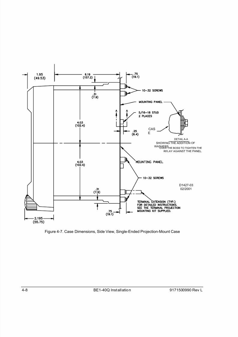
4-8 BE1-40Q Installation 9171500990 Rev L
D1427-03
02/2001
DETAIL A-A
SHOWING THE ADDITION OF
WASHERSOVER THE BOSS TO TIGHTEN THE
RELAY AGAINST THE PANEL.
CAS
E
Figure 4-7. Case Dimensions, Side View, Single-Ended Projection-Mount Case
8/12/2019 BE1 40Q Loss of Excitation Relay
http://slidepdf.com/reader/full/be1-40q-loss-of-excitation-relay 29/45
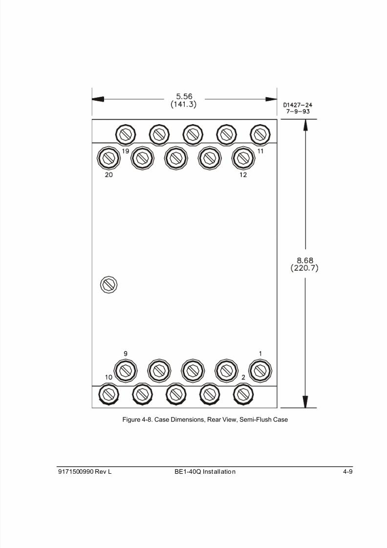
9171500990 Rev L BE1-40Q Installation 4-9
Figure 4-8. Case Dimensions, Rear View, Semi-Flush Case

8/12/2019 BE1 40Q Loss of Excitation Relay
http://slidepdf.com/reader/full/be1-40q-loss-of-excitation-relay 30/45
4-10 BE1-40Q Installation 9171500990 Rev L
Figure 4-9. Case Dimensions, Rear View, Projection-Mount Case

8/12/2019 BE1 40Q Loss of Excitation Relay
http://slidepdf.com/reader/full/be1-40q-loss-of-excitation-relay 31/45
9171500990 Rev L BE1-40Q Installation 4-11
P0002-12
01-31-01
Figure 4-10. Case Cover Dimensions, Front View

8/12/2019 BE1 40Q Loss of Excitation Relay
http://slidepdf.com/reader/full/be1-40q-loss-of-excitation-relay 32/45
4-12 BE1-40Q Installation 9171500990 Rev L
CONNECTIONS
Be sure to check the model and style number of a relay before connecting and energizing the relay.Incorrect wiring may result in damage to the relay. Except where noted, connections should be made withwire no smaller than 14 AWG.
Typical sensing input connections are shown in Figure 4-11. Typical output connections are shown inFigure 4-12. Internal wiring diagrams are shown in Figures 4-13 through 4-15. All connections shown inthis manual assume ABC rotation.
Figure 4-11. Sensing Input Connections

8/12/2019 BE1 40Q Loss of Excitation Relay
http://slidepdf.com/reader/full/be1-40q-loss-of-excitation-relay 33/45
9171500990 Rev L BE1-40Q Installation 4-13
Figure 4-12. Output Connections
Figure 4-13. Interconnection with Current Operated Targets

8/12/2019 BE1 40Q Loss of Excitation Relay
http://slidepdf.com/reader/full/be1-40q-loss-of-excitation-relay 34/45
4-14 BE1-40Q Installation 9171500990 Rev L
Figure 4-14. Interconnection with Current Operated Targets and Power Supply Status Output

8/12/2019 BE1 40Q Loss of Excitation Relay
http://slidepdf.com/reader/full/be1-40q-loss-of-excitation-relay 35/45
9171500990 Rev L BE1-40Q Installation 4-15
Figure 4-15. Interconnection with Internally Operated Target and Auxiliary Output Contacts (SPDT)
MAINTENANCE
BE1-40Q relays require no preventative maintenance other than a periodic operational check. If the relayfails to function properly, contact Technical Sales Support at Basler Electric to coordinate repairs.
STORAGE
This protective relay contains aluminum electrolytic capacitors which generally have a life expectancy in
excess of 10 years at storage temperatures less than 40°C (104°F). Typically, the life expectancy of a
capacitor is cut in half for every 10°C rise in temperature. Storage life can be extended if, at one-yearintervals, power is applied to the relay for a period of 30 minutes.

8/12/2019 BE1 40Q Loss of Excitation Relay
http://slidepdf.com/reader/full/be1-40q-loss-of-excitation-relay 36/45
4-16 BE1-40Q Installation 9171500990 Rev L
This page intentionally left blank.

8/12/2019 BE1 40Q Loss of Excitation Relay
http://slidepdf.com/reader/full/be1-40q-loss-of-excitation-relay 37/45
9171500990 Rev L BE1-40Q Setting and Testing 5-1
SECTION 5 SETTING AND TESTING
SETTING
Setting the pickup value of BE1-40Q relays is facilitated by using the capability curves supplied by thegenerator manufacturer as shown previously in the examples in Section 1. The figure for relay operatingcharacteristics is repeated here as Figure 5-1. Note that the line representing the relay characteristic is
positioned on the curve 8° from horizontal and just above the point where the steady state stability limit
arc intersects the capability curve. (The 8° slope applies to all BE1-40Q relays.)
Figure 5-1. Example of BE1-40Q Relay Operating Characteristics
The pickup setting is determined by the point where the BE1-40Q characteristic intersects the Q axis inper unit (pu) quantities. Therefore, for the example shown in Figure 5-1, the pickup is -0.4 pu. The actualper unit pickup setting for your relay is determined by your specific application.
Per Unit Conversion Example
The per unit quantity is converted to a TAP switch setting by the procedure described in the followingexample.
Given:
Rated power = 100 MVA
Rated voltage = 12.8 kV
CT ratio = 5000/5
PT ratio = 12800/120
Step 1. Determine the desired primary vars.
Three-phase primary vars = 0.4 x rated power
= 0.4 x 100 MVA
= 40 Mvar
Single-phase primary vars = 13.33 Mvar
Step 2. Determine the desired primary current.
Primary current = (single-phase primary var)⎟⎟
⎠
⎞
⎜⎜
⎝
⎛
LLV
3

8/12/2019 BE1 40Q Loss of Excitation Relay
http://slidepdf.com/reader/full/be1-40q-loss-of-excitation-relay 38/45
5-2 BE1-40Q Setting and Testing 9171500990 Rev L
= (13.33 Mvar)⎟⎟
⎠
⎞
⎜⎜
⎝
⎛
12800
3
= 1804 A
Step 3. Specify a BE1-40Q relay having a nominal sensing range of 120 VLL (for a PT ratio of12800/120).
Step 4. Determine the desired secondary current.
Secondary current =RatioCT
CurrentPrimary
=5000/5
1804
= 1.8 A
Step 5. Determine the pickup.
Pickup = relayrelay
IV
×3
= 8.13
120×
= 125
= Low Range, TAP position E (Table 1-1)
OPERATIONAL TEST
Introduction
The following procedures verify proper relay operation and calibration.
Results obtained from these procedures may no fall within specified tolerances. When evaluating results,
consider three prominent factors:• Test equipment accuracy
• Testing method
• External test set components tolerance level
Pickup Verification
Step 1. Connect the test circuit as shown in Figure 5-2. Apply appropriate operating power, dependingon the power supply option (refer to the Style Chart in Section 1), to terminals 3 and 4. ThePOWER LED should illuminate.
Step 2. For relay styles with target indicators, actuate the target reset switch to insure that the target isreset.
Step 3. Make the following front panel adjustments on the BE1-40Q relay:
RANGE switch - LOW position
TAP switch - Position A (minimum)
TIME DELAY switches - 10 (1.0 second)
Step 4. If equipped with a power supply status output relay (option 2-S), verify that the contact is openwhen external power is applied. Remove input power and verify that the status contacts close.Re-apply external power.

8/12/2019 BE1 40Q Loss of Excitation Relay
http://slidepdf.com/reader/full/be1-40q-loss-of-excitation-relay 39/45
9171500990 Rev L BE1-40Q Setting and Testing 5-3
Figure 5-2. Test Circuit Connections
Step 5. Adjust the voltage source to the nominal value of the sensing input as designated by the seconddigit of the style number. (Refer to Table 5-1).
Table 5-1. Nominal Sensing Input Voltage
Second Digit of Style Number Nominal Ac Voltage
2 or 3 120
5 or 6 208
8 or 9 240
Step 6. Adjust the phase of the current source to produce an output that lags the voltage input by 60°.
Step 7. Slowly increase the magnitude of the current source until the PICKUP LED illuminates. On unitswith target indicators, the indicator should illuminate.
Step 8. Note the indicated voltage and current, and calculate the actual pickup value as defined by:
relayrelay
IV
×3
Compare the result with Table 1-1 in Section 1. Reset the target indicator, if present.
NOTE
The equation in Step 8 applies only to Step 8 of the Pickup Verification TestProcedure. For the pickup response of the BE1-40Q relay, see Section 3,Functional Description.
8/12/2019 BE1 40Q Loss of Excitation Relay
http://slidepdf.com/reader/full/be1-40q-loss-of-excitation-relay 40/45
5-4 BE1-40Q Setting and Testing 9171500990 Rev L
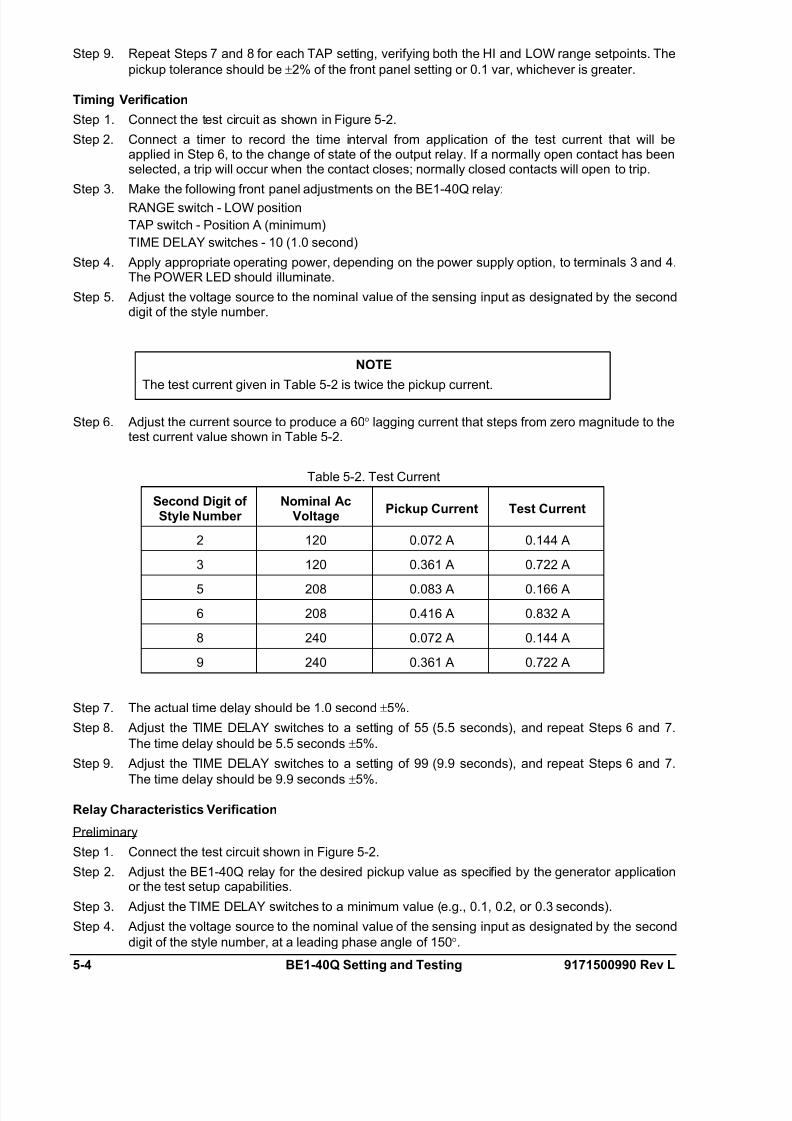
Step 9. Repeat Steps 7 and 8 for each TAP setting, verifying both the HI and LOW range setpoints. The
pickup tolerance should be ±2% of the front panel setting or 0.1 var, whichever is greater.
Timing Verification
Step 1. Connect the test circuit as shown in Figure 5-2.
Step 2. Connect a timer to record the time interval from application of the test current that will beapplied in Step 6, to the change of state of the output relay. If a normally open contact has beenselected, a trip will occur when the contact closes; normally closed contacts will open to trip.
Step 3. Make the following front panel adjustments on the BE1-40Q relay:
RANGE switch - LOW position
TAP switch - Position A (minimum)
TIME DELAY switches - 10 (1.0 second)
Step 4. Apply appropriate operating power, depending on the power supply option, to terminals 3 and 4.The POWER LED should illuminate.
Step 5. Adjust the voltage source to the nominal value of the sensing input as designated by the seconddigit of the style number.
Step 6. Adjust the current source to produce a 60° lagging current that steps from zero magnitude to thetest current value shown in Table 5-2.
Table 5-2. Test Current
Second Digit ofStyle Number
Nominal AcVoltage
Pickup Current Test Current
2 120 0.072 A 0.144 A
3 120 0.361 A 0.722 A
5 208 0.083 A 0.166 A
6 208 0.416 A 0.832 A
8 240 0.072 A 0.144 A
9 240 0.361 A 0.722 A
Step 7. The actual time delay should be 1.0 second ±5%.
Step 8. Adjust the TIME DELAY switches to a setting of 55 (5.5 seconds), and repeat Steps 6 and 7.
The time delay should be 5.5 seconds ±5%.
Step 9. Adjust the TIME DELAY switches to a setting of 99 (9.9 seconds), and repeat Steps 6 and 7.
The time delay should be 9.9 seconds±5%.
Relay Characteristics Verification
Preliminary
Step 1. Connect the test circuit shown in Figure 5-2.
Step 2. Adjust the BE1-40Q relay for the desired pickup value as specified by the generator applicationor the test setup capabilities.
Step 3. Adjust the TIME DELAY switches to a minimum value (e.g., 0.1, 0.2, or 0.3 seconds).
Step 4. Adjust the voltage source to the nominal value of the sensing input as designated by the second
digit of the style number, at a leading phase angle of 150°.
NOTE
The test current given in Table 5-2 is twice the pickup current.
8/12/2019 BE1 40Q Loss of Excitation Relay
http://slidepdf.com/reader/full/be1-40q-loss-of-excitation-relay 41/45
9171500990 Rev L BE1-40Q Setting and Testing 5-5
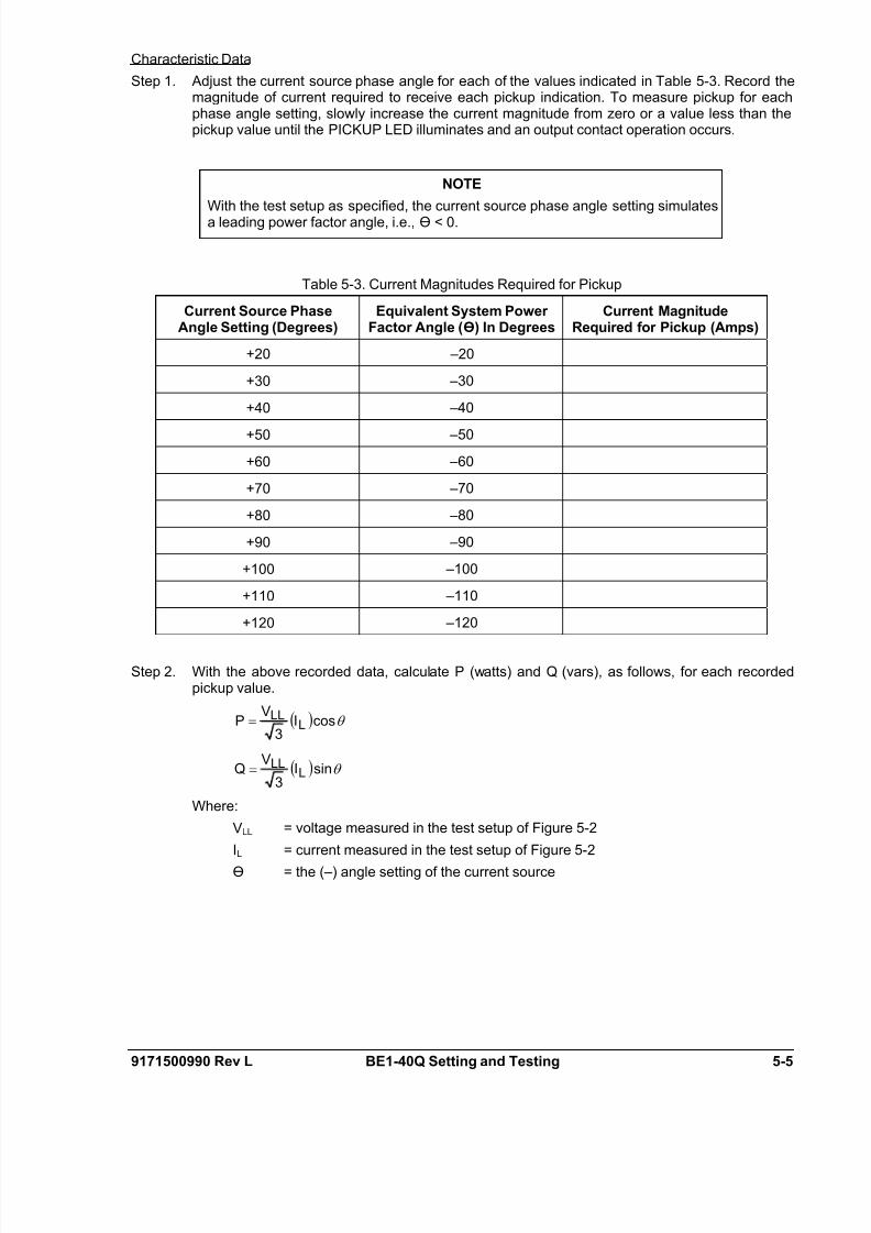
Characteristic Data
Step 1. Adjust the current source phase angle for each of the values indicated in Table 5-3. Record themagnitude of current required to receive each pickup indication. To measure pickup for eachphase angle setting, slowly increase the current magnitude from zero or a value less than thepickup value until the PICKUP LED illuminates and an output contact operation occurs.
Table 5-3. Current Magnitudes Required for Pickup
Current Source PhaseAngle Setting (Degrees)
Equivalent System PowerFactor Angle (Ө) In Degrees
Current MagnitudeRequired for Pickup (Amps)
+20 –20
+30 –30
+40 –40
+50 –50
+60 –60
+70 –70
+80 –80
+90 –90
+100 –100
+110 –110
+120 –120
Step 2. With the above recorded data, calculate P (watts) and Q (vars), as follows, for each recordedpickup value.
( ) θ cos3
LLL I
VP =
( ) θ sin3
LLL I
VQ =
Where:
VLL = voltage measured in the test setup of Figure 5-2
IL = current measured in the test setup of Figure 5-2
Ө = the (–) angle setting of the current source
NOTE
With the test setup as specified, the current source phase angle setting simulatesa leading power factor angle, i.e., Ө < 0.

8/12/2019 BE1 40Q Loss of Excitation Relay
http://slidepdf.com/reader/full/be1-40q-loss-of-excitation-relay 42/45
5-6 BE1-40Q Setting and Testing 9171500990 Rev L
Step 3. The results from the above calculations can now be plotted on a graph of the complex powerplane.
Graph Example
Given:
Relay style number is F3E-E1P-B1S1F. (Reference the Style Chart, Figure 1-4.)
Pickup is set to 125. (Reference Table 1-1.)
Test results are obtained as given in Step 1. For this example, we are using the data shown incolumns [1] and [2] of Table 5-4.
Step 1. Calculate P and Q for a current phase angle of 20° (Ө = –20°).
( ) ( )°−= 20cos806.33
120P
= 247.8 W
( ) ( )°−= 20sin806.33
120Q
= –90.18 vars
Note that the above results for a phase angle of –20° have been entered in Table 5-4, columns[3] and [4], first row. Similarly, the values of P and Q can be solved for the other phase angles of
column [1].
Step 2. Finally, the data from Table 5-4 is shown plotted on the complex power plane shown in Figure5-3. A blank graph is provided as Figure 5-4.
Table 5-4. Data for the Hypothetical Graph of Figure 5-3
[1] [2] [3] [4]
Current SourcePhase Angle Degrees
System PhaseAngle Ө
Current Magnitude forPickup (Amps)
Real Power(Watts)
ReactivePower (Vars)
+20 –20 3.806 247.76 –90.18
+30 –30 2.902 174.12 –100.53
+40 –40 2.404 127.60 –107.07+50 –50 2.107 93.82 –111.81
+60 –60 1.927 66.75 –115.62
+70 –70 1.827 43.28 –118.92
+80 –80 1.788 21.51 –121.98
+90 –90 1.804 0.00 –125.00
+100 –100 1.879 –22.60 –128.18
+110 –110 2.024 –47.95 –131.74
+120 –120 2.267 –78.54 –136.04
NOTE
If: β,II andVV ∠=∝∠=
Then:
Real power (P) = ( ),β-cosIV ∝×
Reactive power (Q) = ( ) and,β-sinIV ∝×
System power factor angle (Ө) = β−∝

8/12/2019 BE1 40Q Loss of Excitation Relay
http://slidepdf.com/reader/full/be1-40q-loss-of-excitation-relay 43/45
9171500990 Rev L BE1-40Q Setting and Testing 5-7
Figure 5-3. BE1-40Q Relay Characteristics Plotted on Complex Power Plane
Figure 5-4. Blank Graph
8/12/2019 BE1 40Q Loss of Excitation Relay
http://slidepdf.com/reader/full/be1-40q-loss-of-excitation-relay 44/45
5-8 BE1-40Q Setting and Testing 9171500990 Rev L
This page intentionally left blank.

8/12/2019 BE1 40Q Loss of Excitation Relay
http://slidepdf.com/reader/full/be1-40q-loss-of-excitation-relay 45/45