beaaqualogic service bus - oracle...services, set up security, manage resources, and capture data...
TRANSCRIPT
BEAAquaLogic Service Bus™
User Guide
Version: 2.1Document Revised: December 2005

CopyrightCopyright © 2005 BEA Systems, Inc. All Rights Reserved.
Restricted Rights LegendThis software and documentation is subject to and made available only pursuant to the terms of the BEA Systems License Agreement and may be used or copied only in accordance with the terms of that agreement. It is against the law to copy the software except as specifically allowed in the agreement. This document may not, in whole or in part, be copied, photocopied, reproduced, translated, or reduced to any electronic medium or machine readable form without prior consent, in writing, from BEA Systems, Inc.
Use, duplication or disclosure by the U.S. Government is subject to restrictions set forth in the BEA Systems License Agreement and in subparagraph (c)(1) of the Commercial Computer Software-Restricted Rights Clause at FAR 52.227-19; subparagraph (c)(1)(ii) of the Rights in Technical Data and Computer Software clause at DFARS 252.227-7013, subparagraph (d) of the Commercial Computer Software--Licensing clause at NASA FAR supplement 16-52.227-86; or their equivalent.
Information in this document is subject to change without notice and does not represent a commitment on the part of BEA Systems. THE SOFTWARE AND DOCUMENTATION ARE PROVIDED “AS IS” WITHOUT WARRANTY OF ANY KIND INCLUDING WITHOUT LIMITATION, ANY WARRANTY OF MERCHANTABILITY OR FITNESS FOR A PARTICULAR PURPOSE. FURTHER, BEA Systems DOES NOT WARRANT, GUARANTEE, OR MAKE ANY REPRESENTATIONS REGARDING THE USE, OR THE RESULTS OF THE USE, OF THE SOFTWARE OR WRITTEN MATERIAL IN TERMS OF CORRECTNESS, ACCURACY, RELIABILITY, OR OTHERWISE.
Trademarks or Service MarksBEA, BEA JRockit, BEA Liquid Data for WebLogic, BEA WebLogic Server, Built on BEA, Jolt, JoltBeans, SteelThread, Top End, Tuxedo, and WebLogic are registered trademarks of BEA Systems, Inc. BEA AquaLogic, BEA AquaLogic Data Services Platform, BEA AquaLogic Enterprise Security, BEA AquaLogic Service Bus, BEA AquaLogic Service Registry, BEA Builder, BEA Campaign Manager for WebLogic, BEA eLink, BEA Manager, BEA MessageQ, BEA WebLogic Commerce Server, BEA WebLogic Enterprise, BEA WebLogic Enterprise Platform, BEA WebLogic Enterprise Security, BEA WebLogic Express, BEA WebLogic Integration, BEA WebLogic Java Adapter for Mainframe, BEA WebLogic JDriver, BEA WebLogic JRockit, BEA WebLogic Log Central, BEA WebLogic Personalization Server, BEA WebLogic Platform, BEA WebLogic Portal, BEA WebLogic Server Process Edition, BEA WebLogic WorkGroup Edition, BEA WebLogic Workshop, and Liquid Computing are trademarks of BEA Systems, Inc. BEA Mission Critical Support is a service mark of BEA Systems, Inc. All other company and product names may be the subject of intellectual property rights reserved by third parties.
All other trademarks are the property of their respective companies.

BEA AquaLogic Service Bus User Guide iii
Contents
1. Introduction
2. Modeling Message Flow in AquaLogic Service BusAbout AquaLogic Service Bus Message Flow . . . . . . . . . . . . . . . . . . . . . . . . . . . . . . . . . 2-2
Building a Message Flow . . . . . . . . . . . . . . . . . . . . . . . . . . . . . . . . . . . . . . . . . . . . . . 2-3
Message Execution . . . . . . . . . . . . . . . . . . . . . . . . . . . . . . . . . . . . . . . . . . . . . . . . . . . 2-5
Pipelines . . . . . . . . . . . . . . . . . . . . . . . . . . . . . . . . . . . . . . . . . . . . . . . . . . . . . . . . . . . . . . . 2-5
Branching in Message Flows . . . . . . . . . . . . . . . . . . . . . . . . . . . . . . . . . . . . . . . . . . . . . . . 2-8
Operational Branching . . . . . . . . . . . . . . . . . . . . . . . . . . . . . . . . . . . . . . . . . . . . . . . . 2-8
Conditional Branching . . . . . . . . . . . . . . . . . . . . . . . . . . . . . . . . . . . . . . . . . . . . . . . . 2-9
Performing Transformations . . . . . . . . . . . . . . . . . . . . . . . . . . . . . . . . . . . . . . . . . . . . . . 2-10
Configuring Single or Multiple Stages in Pipelines. . . . . . . . . . . . . . . . . . . . . . . . . . . . . 2-12
Using Multiple Stages. . . . . . . . . . . . . . . . . . . . . . . . . . . . . . . . . . . . . . . . . . . . . . . . 2-13
Handling Errors . . . . . . . . . . . . . . . . . . . . . . . . . . . . . . . . . . . . . . . . . . . . . . . . . . . . . . . . 2-14
Generating the Error Message, Reporting, and Replying . . . . . . . . . . . . . . . . . . . . . 2-15
Example . . . . . . . . . . . . . . . . . . . . . . . . . . . . . . . . . . . . . . . . . . . . . . . . . . . . . . . . . . 2-16
Selecting a Service Type . . . . . . . . . . . . . . . . . . . . . . . . . . . . . . . . . . . . . . . . . . . . . . . . . 2-18
Use a WSDL to Define a Service . . . . . . . . . . . . . . . . . . . . . . . . . . . . . . . . . . . . . . . 2-19
Choosing a WSDL Port or Binding? . . . . . . . . . . . . . . . . . . . . . . . . . . . . . . . . . . . . 2-20
Any SOAP or Any XML Service Types. . . . . . . . . . . . . . . . . . . . . . . . . . . . . . . . . . 2-21
Messaging Service Type . . . . . . . . . . . . . . . . . . . . . . . . . . . . . . . . . . . . . . . . . . . . . . 2-21
Dynamic Routing . . . . . . . . . . . . . . . . . . . . . . . . . . . . . . . . . . . . . . . . . . . . . . . . . . . . . . . 2-21

iv BEA AquaLogic Service Bus User Guide
Message Context . . . . . . . . . . . . . . . . . . . . . . . . . . . . . . . . . . . . . . . . . . . . . . . . . . . . . . . 2-22
Key Context Manipulation Facts . . . . . . . . . . . . . . . . . . . . . . . . . . . . . . . . . . . . . . . 2-24
Copying JMS Properties From Inbound to Outbound . . . . . . . . . . . . . . . . . . . . . . . 2-25
RPC and Document Style SOAP . . . . . . . . . . . . . . . . . . . . . . . . . . . . . . . . . . . . . . . . . . 2-25
RPC Web Services . . . . . . . . . . . . . . . . . . . . . . . . . . . . . . . . . . . . . . . . . . . . . . . . . . 2-26
Document Style SOAP. . . . . . . . . . . . . . . . . . . . . . . . . . . . . . . . . . . . . . . . . . . . . . . 2-28
Variable Structures . . . . . . . . . . . . . . . . . . . . . . . . . . . . . . . . . . . . . . . . . . . . . . . . . . . . . 2-31
Quality of Service . . . . . . . . . . . . . . . . . . . . . . . . . . . . . . . . . . . . . . . . . . . . . . . . . . . . . . 2-45
Delivery Guarantees. . . . . . . . . . . . . . . . . . . . . . . . . . . . . . . . . . . . . . . . . . . . . . . . . 2-45
Outbound Message Retries . . . . . . . . . . . . . . . . . . . . . . . . . . . . . . . . . . . . . . . . . . . 2-50
Content Types, JMS Type, and Encoding. . . . . . . . . . . . . . . . . . . . . . . . . . . . . . . . . . . . 2-51
Asynchronous Request/Response . . . . . . . . . . . . . . . . . . . . . . . . . . . . . . . . . . . . . . . . . . 2-51
JMS Correlation ID . . . . . . . . . . . . . . . . . . . . . . . . . . . . . . . . . . . . . . . . . . . . . . . . . 2-52
WS-I Compliance . . . . . . . . . . . . . . . . . . . . . . . . . . . . . . . . . . . . . . . . . . . . . . . . . . . . . . 2-53
WS-I Compliance Checks . . . . . . . . . . . . . . . . . . . . . . . . . . . . . . . . . . . . . . . . . . . . 2-54
3. Securing Inbound and Outbound MessagesAquaLogic Service Bus Security FAQ . . . . . . . . . . . . . . . . . . . . . . . . . . . . . . . . . . . . . . . 3-2
About AquaLogic Service Bus Security . . . . . . . . . . . . . . . . . . . . . . . . . . . . . . . . . . . . . . 3-7
WebLogic Server Prerequisites. . . . . . . . . . . . . . . . . . . . . . . . . . . . . . . . . . . . . . . . . . . . . 3-9
Main Steps for Securing AquaLogic Service Bus Domains . . . . . . . . . . . . . . . . . . . 3-9
Details and Options for Securing AquaLogic Service Bus Domains . . . . . . . . . . . 3-10
Transport-Level Security. . . . . . . . . . . . . . . . . . . . . . . . . . . . . . . . . . . . . . . . . . . . . . . . . 3-13
HTTPS Transport-Level Security . . . . . . . . . . . . . . . . . . . . . . . . . . . . . . . . . . . . . . 3-13
Inbound HTTPS Transport-Level Security. . . . . . . . . . . . . . . . . . . . . . . . . . . . 3-15
Outbound HTTPS Transport-Level Security . . . . . . . . . . . . . . . . . . . . . . . . . . 3-18
HTTP Transport-Level Security . . . . . . . . . . . . . . . . . . . . . . . . . . . . . . . . . . . . . . . 3-19
Security for JMS, Email, FTP, and File Transport . . . . . . . . . . . . . . . . . . . . . . . . . . 3-20

BEA AquaLogic Service Bus User Guide v
JMS Transport-Level Security . . . . . . . . . . . . . . . . . . . . . . . . . . . . . . . . . . . . . 3-20
Email and FTP Transport-Level Security . . . . . . . . . . . . . . . . . . . . . . . . . . . . . 3-23
File Transport Security . . . . . . . . . . . . . . . . . . . . . . . . . . . . . . . . . . . . . . . . . . . 3-23
Transport-Level Security in Message Flow and Service Callout Actions . . . . . . . . 3-23
Message-Level Security (Web Services Security) . . . . . . . . . . . . . . . . . . . . . . . . . . . . . 3-24
About Web Services Security . . . . . . . . . . . . . . . . . . . . . . . . . . . . . . . . . . . . . . . . . . 3-24
Inbound Web Services Security . . . . . . . . . . . . . . . . . . . . . . . . . . . . . . . . . . . . . . . . 3-26
About Inbound Web Services Security . . . . . . . . . . . . . . . . . . . . . . . . . . . . . . . 3-26
Client Request and Proxy Service Response. . . . . . . . . . . . . . . . . . . . . . . . . . . 3-26
How to Configure a WS-Security Pass-Through Scenario . . . . . . . . . . . . . . . . 3-27
How to Configure an Active Intermediary WS-Security Proxy Service . . . . . 3-28
Outbound Web Services Security . . . . . . . . . . . . . . . . . . . . . . . . . . . . . . . . . . . . . . . 3-29
About Outbound Web Services Security. . . . . . . . . . . . . . . . . . . . . . . . . . . . . . 3-30
How to Configure Outbound Web Services Security . . . . . . . . . . . . . . . . . . . . 3-30
Disabling Outbound WS-Security in the Pipeline. . . . . . . . . . . . . . . . . . . . . . . 3-33
Web Service Policy . . . . . . . . . . . . . . . . . . . . . . . . . . . . . . . . . . . . . . . . . . . . . . . . . . . . . 3-33
About Web Service Policy . . . . . . . . . . . . . . . . . . . . . . . . . . . . . . . . . . . . . . . . . . . . 3-34
Web Services Policy Attachment . . . . . . . . . . . . . . . . . . . . . . . . . . . . . . . . . . . . . . . 3-35
Effective Policy . . . . . . . . . . . . . . . . . . . . . . . . . . . . . . . . . . . . . . . . . . . . . . . . . . . . 3-37
Out-of-the-Box WS-Policy Statements . . . . . . . . . . . . . . . . . . . . . . . . . . . . . . . . . . 3-38
SAML Support. . . . . . . . . . . . . . . . . . . . . . . . . . . . . . . . . . . . . . . . . . . . . . . . . . . . . . . . . 3-41
Identity Propagation . . . . . . . . . . . . . . . . . . . . . . . . . . . . . . . . . . . . . . . . . . . . . . . . . 3-41
Pass-Through Identity Propagation . . . . . . . . . . . . . . . . . . . . . . . . . . . . . . . . . . . . . 3-42
SAML Credential Mapping . . . . . . . . . . . . . . . . . . . . . . . . . . . . . . . . . . . . . . . . . . . 3-42
Inbound Authentication with a SAML WS-Security Token . . . . . . . . . . . . . . . . . . 3-43
Troubleshooting SAML Web Services Security. . . . . . . . . . . . . . . . . . . . . . . . . . . . 3-45
Access Control. . . . . . . . . . . . . . . . . . . . . . . . . . . . . . . . . . . . . . . . . . . . . . . . . . . . . . . . . 3-46
About Access Control. . . . . . . . . . . . . . . . . . . . . . . . . . . . . . . . . . . . . . . . . . . . . . . . 3-46

vi BEA AquaLogic Service Bus User Guide
Users. . . . . . . . . . . . . . . . . . . . . . . . . . . . . . . . . . . . . . . . . . . . . . . . . . . . . . . . . . . . . 3-47
Groups . . . . . . . . . . . . . . . . . . . . . . . . . . . . . . . . . . . . . . . . . . . . . . . . . . . . . . . . . . . 3-47
Security Roles . . . . . . . . . . . . . . . . . . . . . . . . . . . . . . . . . . . . . . . . . . . . . . . . . . . . . 3-48
Role-Based Access in AquaLogic Service Bus Console . . . . . . . . . . . . . . . . . 3-49
Credentials . . . . . . . . . . . . . . . . . . . . . . . . . . . . . . . . . . . . . . . . . . . . . . . . . . . . . . . . 3-55
Service Accounts . . . . . . . . . . . . . . . . . . . . . . . . . . . . . . . . . . . . . . . . . . . . . . . 3-55
Proxy Service Providers . . . . . . . . . . . . . . . . . . . . . . . . . . . . . . . . . . . . . . . . . . 3-56
Configuring Credentials . . . . . . . . . . . . . . . . . . . . . . . . . . . . . . . . . . . . . . . . . . 3-57
Configuring Proxy Service Access Control . . . . . . . . . . . . . . . . . . . . . . . . . . . 3-58
Securing AquaLogic Service Bus for a Production Environment. . . . . . . . . . . . . . . . . . 3-59
4. Using the Test ConsoleFeatures . . . . . . . . . . . . . . . . . . . . . . . . . . . . . . . . . . . . . . . . . . . . . . . . . . . . . . . . . . . 4-2
Prerequisites . . . . . . . . . . . . . . . . . . . . . . . . . . . . . . . . . . . . . . . . . . . . . . . . . . . . . . . . 4-2
Testing Proxy Services . . . . . . . . . . . . . . . . . . . . . . . . . . . . . . . . . . . . . . . . . . . . . . . . . . . 4-2
Direct Calls . . . . . . . . . . . . . . . . . . . . . . . . . . . . . . . . . . . . . . . . . . . . . . . . . . . . . . . . 4-3
Indirect Calls . . . . . . . . . . . . . . . . . . . . . . . . . . . . . . . . . . . . . . . . . . . . . . . . . . . . . . . 4-3
HTTP Requests . . . . . . . . . . . . . . . . . . . . . . . . . . . . . . . . . . . . . . . . . . . . . . . . . . . . . 4-4
Testing Business Services . . . . . . . . . . . . . . . . . . . . . . . . . . . . . . . . . . . . . . . . . . . . . . . . . 4-5
Transport Security . . . . . . . . . . . . . . . . . . . . . . . . . . . . . . . . . . . . . . . . . . . . . . . . . . . 4-5
Recommended Approaches to Testing Proxy and Business Services. . . . . . . . . . . . . . . . 4-5
Tracing Proxy Services Using the Test Console. . . . . . . . . . . . . . . . . . . . . . . . . . . . . . . . 4-7
Example: Testing and Tracing a Proxy Service . . . . . . . . . . . . . . . . . . . . . . . . . . . . . 4-8
Testing Resources . . . . . . . . . . . . . . . . . . . . . . . . . . . . . . . . . . . . . . . . . . . . . . . . . . . . . . 4-12
MFL . . . . . . . . . . . . . . . . . . . . . . . . . . . . . . . . . . . . . . . . . . . . . . . . . . . . . . . . . . . . . 4-12
Example . . . . . . . . . . . . . . . . . . . . . . . . . . . . . . . . . . . . . . . . . . . . . . . . . . . . . . 4-13
XSLT . . . . . . . . . . . . . . . . . . . . . . . . . . . . . . . . . . . . . . . . . . . . . . . . . . . . . . . . . . . . 4-14
XQuery. . . . . . . . . . . . . . . . . . . . . . . . . . . . . . . . . . . . . . . . . . . . . . . . . . . . . . . . . . . 4-14

BEA AquaLogic Service Bus User Guide vii
Performing In-line XQuery Testing. . . . . . . . . . . . . . . . . . . . . . . . . . . . . . . . . . . . . . . . . 4-16
Testing Services With Web Service Security . . . . . . . . . . . . . . . . . . . . . . . . . . . . . . . . . 4-17
Test Console Transport Settings . . . . . . . . . . . . . . . . . . . . . . . . . . . . . . . . . . . . . . . . . . . 4-22
5. MonitoringMonitoring Scenarios. . . . . . . . . . . . . . . . . . . . . . . . . . . . . . . . . . . . . . . . . . . . . . . . . . . . . 5-1
About Monitoring . . . . . . . . . . . . . . . . . . . . . . . . . . . . . . . . . . . . . . . . . . . . . . . . . . . . . . . 5-3
Aggregation Interval. . . . . . . . . . . . . . . . . . . . . . . . . . . . . . . . . . . . . . . . . . . . . . . . . . 5-4
Monitoring Architecture. . . . . . . . . . . . . . . . . . . . . . . . . . . . . . . . . . . . . . . . . . . . . . . 5-4
Monitoring Services . . . . . . . . . . . . . . . . . . . . . . . . . . . . . . . . . . . . . . . . . . . . . . . . . . 5-6
Refresh Rate of Monitored Information. . . . . . . . . . . . . . . . . . . . . . . . . . . . . . . . . . . 5-7
Dashboard. . . . . . . . . . . . . . . . . . . . . . . . . . . . . . . . . . . . . . . . . . . . . . . . . . . . . . . . . . 5-7
Service Summary. . . . . . . . . . . . . . . . . . . . . . . . . . . . . . . . . . . . . . . . . . . . . . . . . . . . . . . . 5-9
About the Service Summary. . . . . . . . . . . . . . . . . . . . . . . . . . . . . . . . . . . . . . . . . . . . 5-9
Service Monitoring Summary . . . . . . . . . . . . . . . . . . . . . . . . . . . . . . . . . . . . . . . . . 5-10
Service Monitoring Details. . . . . . . . . . . . . . . . . . . . . . . . . . . . . . . . . . . . . . . . . . . . 5-12
Server Summary . . . . . . . . . . . . . . . . . . . . . . . . . . . . . . . . . . . . . . . . . . . . . . . . . . . . . . . 5-16
About the Server Summary . . . . . . . . . . . . . . . . . . . . . . . . . . . . . . . . . . . . . . . . . . . 5-17
Log Summary . . . . . . . . . . . . . . . . . . . . . . . . . . . . . . . . . . . . . . . . . . . . . . . . . . . . . . 5-17
Server Summary . . . . . . . . . . . . . . . . . . . . . . . . . . . . . . . . . . . . . . . . . . . . . . . . . . . . 5-20
Server Details . . . . . . . . . . . . . . . . . . . . . . . . . . . . . . . . . . . . . . . . . . . . . . . . . . . . . . 5-22
Alert Summary. . . . . . . . . . . . . . . . . . . . . . . . . . . . . . . . . . . . . . . . . . . . . . . . . . . . . . . . . 5-24
About the Alert Summary . . . . . . . . . . . . . . . . . . . . . . . . . . . . . . . . . . . . . . . . . . . . 5-24
System Alerts History. . . . . . . . . . . . . . . . . . . . . . . . . . . . . . . . . . . . . . . . . . . . . . . . 5-26
System Alert Details. . . . . . . . . . . . . . . . . . . . . . . . . . . . . . . . . . . . . . . . . . . . . . . . . 5-28
View Alert Rule Details . . . . . . . . . . . . . . . . . . . . . . . . . . . . . . . . . . . . . . . . . . . . . . 5-29
Alert Rules . . . . . . . . . . . . . . . . . . . . . . . . . . . . . . . . . . . . . . . . . . . . . . . . . . . . . . . . . . . . 5-30
About Alert Rules. . . . . . . . . . . . . . . . . . . . . . . . . . . . . . . . . . . . . . . . . . . . . . . . . . . 5-30

viii BEA AquaLogic Service Bus User Guide
Some Uses for Alerts . . . . . . . . . . . . . . . . . . . . . . . . . . . . . . . . . . . . . . . . . . . . . . . . 5-31
Understanding Alert Rules. . . . . . . . . . . . . . . . . . . . . . . . . . . . . . . . . . . . . . . . . . . . 5-32
6. ReportingReporting Scenarios . . . . . . . . . . . . . . . . . . . . . . . . . . . . . . . . . . . . . . . . . . . . . . . . . . . . . 6-2
Reporting Framework . . . . . . . . . . . . . . . . . . . . . . . . . . . . . . . . . . . . . . . . . . . . . . . . . . . . 6-3
JMS Reporting Provider . . . . . . . . . . . . . . . . . . . . . . . . . . . . . . . . . . . . . . . . . . . . . . . . . . 6-4
About the JMS Reporting Provider . . . . . . . . . . . . . . . . . . . . . . . . . . . . . . . . . . . . . . 6-5
How to Enable Message Reporting. . . . . . . . . . . . . . . . . . . . . . . . . . . . . . . . . . . . . . . . . . 6-6
Using the Reporting Module . . . . . . . . . . . . . . . . . . . . . . . . . . . . . . . . . . . . . . . . . . . . . . . 6-7
Summary of Messages . . . . . . . . . . . . . . . . . . . . . . . . . . . . . . . . . . . . . . . . . . . . . . . . 6-8
View Message Details . . . . . . . . . . . . . . . . . . . . . . . . . . . . . . . . . . . . . . . . . . . . . . . . 6-9
Purging Messages. . . . . . . . . . . . . . . . . . . . . . . . . . . . . . . . . . . . . . . . . . . . . . . . . . . 6-12
Configuring a Database for the JMS Reporting Provider Store. . . . . . . . . . . . . . . . 6-13
Configuring a Database in a Development Environment . . . . . . . . . . . . . . . . . 6-13
Configuring a Database for Production . . . . . . . . . . . . . . . . . . . . . . . . . . . . . . 6-14
Removing, Stopping, or Untargeting a Reporting Provider . . . . . . . . . . . . . . . . . . . . . . 6-14
Stopping a Reporting Provider when the Server is Running . . . . . . . . . . . . . . . . . . 6-15
Untargeting a Reporting Provider when the Server is Running. . . . . . . . . . . . . . . . 6-16
Untargeting the JMS Reporting Provider—Server Not Running . . . . . . . . . . . . . . 6-17
7. Tracing
8. UDDIOverview of BEA AquaLogic Service Bus and UDDI. . . . . . . . . . . . . . . . . . . . . . . . . . . 8-1
Basic Concepts of the UDDI Specification . . . . . . . . . . . . . . . . . . . . . . . . . . . . . . . . 8-2
Benefits of Using a UDDI Registry with AquaLogic Service Bus . . . . . . . . . . . . . . 8-2
Introduction to UDDI Entities . . . . . . . . . . . . . . . . . . . . . . . . . . . . . . . . . . . . . . . . . . 8-3
Prerequisites . . . . . . . . . . . . . . . . . . . . . . . . . . . . . . . . . . . . . . . . . . . . . . . . . . . . . . . . 8-5

BEA AquaLogic Service Bus User Guide ix
Certification . . . . . . . . . . . . . . . . . . . . . . . . . . . . . . . . . . . . . . . . . . . . . . . . . . . . . . . . 8-5
Features. . . . . . . . . . . . . . . . . . . . . . . . . . . . . . . . . . . . . . . . . . . . . . . . . . . . . . . . . . . . 8-5
What is the BEA AquaLogic Service Registry?. . . . . . . . . . . . . . . . . . . . . . . . . . . . . 8-6
Sample Business Scenario for AquaLogic Service Bus and UDDI . . . . . . . . . . . . . . 8-6
Cross-Domain Deployment in AquaLogic Service Bus . . . . . . . . . . . . . . . . . . . 8-7
Using AquaLogic Service Bus and UDDI. . . . . . . . . . . . . . . . . . . . . . . . . . . . . . . . . . . . . 8-8
Typical Workflow. . . . . . . . . . . . . . . . . . . . . . . . . . . . . . . . . . . . . . . . . . . . . . . . . . . . 8-8
Configuring a Registry . . . . . . . . . . . . . . . . . . . . . . . . . . . . . . . . . . . . . . . . . . . . . . . . . . . 8-9
Publishing a Proxy Service to a UDDI Registry . . . . . . . . . . . . . . . . . . . . . . . . . . . . . . . 8-11
Importing a Service from a Registry . . . . . . . . . . . . . . . . . . . . . . . . . . . . . . . . . . . . . . . . 8-12
Mapping AquaLogic Service Bus Proxy Services to UDDI Entities . . . . . . . . . . . . . . . 8-13
UDDI Mapping Details for an AquaLogic Service Bus Proxy Service . . . . . . . . . . 8-16
Transport Attributes . . . . . . . . . . . . . . . . . . . . . . . . . . . . . . . . . . . . . . . . . . . . . . . . . 8-18
Service Type Attributes . . . . . . . . . . . . . . . . . . . . . . . . . . . . . . . . . . . . . . . . . . . . . . 8-20
Canonical tModels Supporting AquaLogic Service Bus Services . . . . . . . . . . . . . . . . . 8-21
Example . . . . . . . . . . . . . . . . . . . . . . . . . . . . . . . . . . . . . . . . . . . . . . . . . . . . . . . . . . . . . . 8-23
A. Tuning AquaLogic Service Bus
B. Debugging AquaLogic Service Bus
C. XQuery Implementation

x BEA AquaLogic Service Bus User Guide

BEA AquaLogic Service Bus User Guide 1-1
C H A P T E R 1
Introduction
BEA AquaLogic Service Bus is part of BEA’s new AquaLogic family of Service Infrastructure Products. AquaLogic Service Bus manages the routing and transformation of messages in an enterprise system. Combined with its monitoring and administration capability, AquaLogic Service Bus provides a unified software product for implementing and deploying your Service-Oriented Architecture (SOA).
AquaLogic Service Bus is a configuration-based, policy-driven Enterprise Service Bus (ESB). From the AquaLogic Service Bus Console, you can monitor your services, servers, and operational tasks. The console provides you with the ability to configure proxy and business services, set up security, manage resources, and capture data for tracking or regulatory auditing. The AquaLogic Service Bus Console enables you to respond rapidly and effectively to changes in your service-oriented environment.
AquaLogic Service Bus relies on WebLogic Server run-time facilities. It leverages WebLogic Server capabilities to deliver functionality that is highly available, scalable, and reliable.
This guide provides detailed information on using and configuring AquaLogic Service Bus. It is intended for those responsible for messaging and SOA, such as enterprise architects, operations specialists, security architects and developers, application architects and developers, server and application administrators, and support engineers.
While sometimes providing procedural information, this guide does not provide detailed information on how to configure resources using the AquaLogic Service Bus Console. To learn how to use the AquaLogic Service Bus Console, see Using the AquaLogic Service Bus Console.

In t roduc t i on
1-2 BEA AquaLogic Service Bus User Guide
This document includes the following topics:
Modeling Message Flow in AquaLogic Service Bus—presents guidelines to follow when you model message flows in AquaLogic Service Bus. A message flow defines the implementation of a proxy service, which is the AquaLogic Service Bus definition of an intermediary Web services that is hosted locally on AquaLogic Service Bus. In AquaLogic Service Bus, service clients exchange messages with an intermediary proxy service instead of directly with a business service.
Securing Inbound and Outbound Messages—contains the information that you need to secure messages when using AquaLogic Service Bus, including transport configuration, Web Service Policy, access-control security, and securing AquaLogic Service Bus for a Production Environment.
Monitoring—contains information about monitoring and collecting run-time information for systems operations and business auditing purposes. Describes how you can monitor the health of the system, including the state of the services, servers, and Service Level Agreement (SLA) violations.
Reporting—contains information on how to capture message data for tracking messages or regulatory auditing. This section also contains information about setting up your own reporting provider; using the JMS reporting provider included with AquaLogic Service Bus; using the Reporting module in AquaLogic Service Bus Console; and configuring a reporting provider for alert data. Alerts contain information about SLA violations.
Tracing—contains information on how to trace messages without shutting down the server. This feature is useful in both a development and production environment. This feature allows you to troubleshoot and diagnose a message flow in one or more proxy services.
UDDI—contains information about how to use Universal Description, Discovery and Integration (UDDI) registries with AquaLogic Service Bus. The UDDI protocol is one of the major building blocks required for successful Web services. UDDI creates a standard interoperable platform that enables companies and applications to find and use Web services over the Internet.
Tuning AquaLogic Service Bus—provides tips on tuning AquaLogic Service Bus in a production environment.
Debugging AquaLogic Service Bus—this appendix provides information about enabling debugging for different modules in AquaLogic Service Bus.

BEA AquaLogic Service Bus User Guide 2-1
C H A P T E R 2
Modeling Message Flow in AquaLogic Service Bus
In BEA AquaLogic Service Bus, Message Flow defines the implementation of a proxy service. This section presents some guidelines to follow when you model message flows in AquaLogic Service Bus. Configuration of AquaLogic Service Bus is performed in the AquaLogic Service Bus Console, which is described in the Using the AquaLogic Service Bus Console.
This section includes the following topics:
About AquaLogic Service Bus Message Flow
Pipelines
Branching in Message Flows
Performing Transformations
Configuring Single or Multiple Stages in Pipelines
Handling Errors
Selecting a Service Type
Dynamic Routing
Message Context
RPC and Document Style SOAP
Variable Structures
Quality of Service

Mode l ing Message F l ow in AquaLog ic Ser v ice Bus
2-2 BEA AquaLogic Service Bus User Guide
Content Types, JMS Type, and Encoding
Asynchronous Request/Response
WS-I Compliance
About AquaLogic Service Bus Message FlowMessage Flows are the definitions of AquaLogic Service Bus proxy services. Pipelines, branch nodes, and route nodes define the implementation of AquaLogic Service Bus proxy services. Using the AquaLogic Service Bus Console, you configure the logic for the manipulation of messages in proxy service message flow definitions. This logic includes such activities as transformation, publishing, and reporting—the logic is configured in individual actions within the message flow.
The followng figure shows a high level view of the components of the message flow definition.
Figure 2-1 Components of Message Flows

About AquaLog ic Se rv i ce Bus Message F l ow
BEA AquaLogic Service Bus User Guide 2-3
This topic includes the following sections:
Building a Message Flow
Message Execution
Building a Message FlowAny element may appear at the root of the message flow. One of the simplest of message flow designs is to have only a route node representing the entire flow. There is also no restriction on what two elements you can chain together. For example, two pipeline pair nodes can be chained together without a branch node in between. With regards to branching, each branch can start with a different element. One branch can terminate with a route node, another can be followed by a pipeline pair, and yet another may have no descendant. In the latter case, a branch with no descendants means that at run time, when this branch is executed, response processing begins immediately. However, in general a message flow is likely to come in two forms:
In the case of non-operational services (services that are not based on WSDLs with operations), the flow is likely to consist of a single pipeline pair at the root followed by a route node.
In the case of operational services, the flow is likely to consist of a single pipeline pair at the root, followed by a branch node based on operation, with each branch consisting of a pipeline pair followed by a route node.
A message flow is constructed by chaining together instances of the top-level components described in the following table. Subsequent sections in this topic describe the node types in more detail.
Table 2-1 Message Flow Components
Node Type Summary
Pipeline Pair
See “Pipelines” on page 2-5.
A pipeline pair ties together a single request and a single response pipeline into one top-level element. A pipeline pair node can have only 1 direct descendant in the message flow. During request processing, only the request pipeline is executed when visiting a pipeline pair node. When reversing the path for response processing, only the response pipeline is executed.
See Table 2-3 for a simple pipeline pair node.
To learn how to configure a pipeline pair node, see “Adding a Pipeline Pair Node” in Proxy Services: Message Flow in Using the AquaLogic Service Bus Console.

Mode l ing Message F l ow in AquaLog ic Ser v ice Bus
2-4 BEA AquaLogic Service Bus User Guide
To learn how to create a message flow, see “Viewing and Changing Message Flow” in Proxy Services: Message Flow in Using the AquaLogic Service Bus Console.
Branch
See “Branching in Message Flows” on page 2-8
A branch node enables processing to proceed down exactly one of several possible paths. Branching is driven by an XPath-based switch table. Each branch in the table specifies a condition (for example, <500) that is evaluated in order against a single XPath expression (for example, ./ns:PurchaseOrder/ns:totalCost on $body). Whichever condition is satisfied first determines which branch is followed. If no branch condition is satisfied, then the default branch, which is always present, is followed. A branch node may have several descendants in the message flow: one for each branch, including the default branch.
To learn how to add a branch node, see “Adding a Conditional Branch Node” in Proxy Services: Message Flow in the Using the AquaLogic Service Bus Console.
For information about working with the message context variables to design conditions, see Message Context in the Using the AquaLogic Service Bus Console.
Route A route node is used to perform request/response communication with another service. It represents the boundary between request and response processing for the proxy service. When the route node dispatches a request message, the request processing is considered complete. When the route node receives a response message, the response processing begins. The route node supports conditional routing as well as request and response transformations.
As the route node represents the boundary between request and response processing, it cannot have any descendants in the message flow.
To learn how to add a route node, see “Adding a Route Node” in Proxy Services: Message Flow in the Using the AquaLogic Service Bus Console.
Node Type Summary

Pipe l ines
BEA AquaLogic Service Bus User Guide 2-5
Message ExecutionThe following table demonstrates the path of a message in a typical message flow.
Table 2-2 Path of a Message Through a Message Flow
PipelinesA principle component in a proxy service’s implementation is the pipeline. A pipeline is a named sequence of stages representing a non-branching one-way processing path.
Pipelines are typed into one of three categories:
Request—Request pipelines are used for processing the request path of the message flow.
Response—Response pipelines are used for processing the response path of the message flow.
Message Flow Node What Happens to Message Processing?
Request Processing Request processing begins at the root of the message flow.
Pipeline Pair Executes the request pipeline only.
Branch Evaluates the branch table and proceeds down the relevant branch.
Route Performs the route along with any request transformations.
Note: Whether or not any routing is performed, the route node represents the change over from request processing to response processing. When a response comes in, the message processing proceeds along the reverses path it took for the request. The same thing occurs for any request path that ends without a route node—that is, without waiting for any response in this case, response processing is initiated.
Response Processing
Route Executes any response transformations.See Route for Request Processing.
Branch Skips any branch nodes and continues with the node that preceded the branch.
Pipeline Pair Executes the response pipeline.
Root of the Message Flow
Sends the response back to the client.

Mode l ing Message F l ow in AquaLog ic Ser v ice Bus
2-6 BEA AquaLogic Service Bus User Guide
Error—Error pipelines are designed to handle errors for stages and nodes in a message flow, and also at the level of the message flow (service).
To create the request and response paths, request and response pipelines are paired and organized into a single node called a pipeline pair node.
The following figure shows an example of a simple message flow. It defines a proxy service named loanGateway3.
Figure 2-2 Message Flow Definition for a Proxy Service
The message flow in the preceding figure shows:
A start node—the root of the tree structure for the loanGateway3 proxy service
A pipeline pair node (PipelinePairNode1), which includes request and response pipelines. The request pipeline includes one stage (validate loan application). The
icon associated with the validate loan application stage indicates that an error handler is defined for this stage. To learn more about error handlers, which are also implemented as message flows, see “Handling Errors” on page 2-14.
A Route node (Route to Normal Loan Processing Service)
In addition to the view of the message flow shown in the preceding figure, the AquaLogic Service Bus Console displays the corresponding tree view map of the message flow to help you navigate components of a message flow at design time.

Pipe l ines
BEA AquaLogic Service Bus User Guide 2-7
Figure 2-3 Message Flow Definition for a Proxy Service
To view or edit the components of the message flow, you can click the component in either the graphical message flow view or the map (tree) view.
This flow structure provides a clear overview of the message flow behavior in design time, making both routes and branch conditions explicit parts of the overall design, rather than locating them out of view inside a pipeline stage or route node. A branch node allows you to conditionally execute these pipeline pairs, and route nodes at the ends of the branches perform the request and response dispatching. To learn more about branch nodes, see Branching in Message Flows.
Mode l ing Message F l ow in AquaLog ic Ser v ice Bus
2-8 BEA AquaLogic Service Bus User Guide
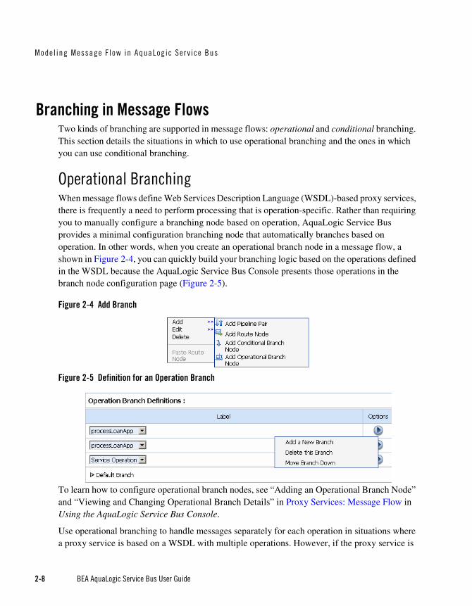
Branching in Message FlowsTwo kinds of branching are supported in message flows: operational and conditional branching. This section details the situations in which to use operational branching and the ones in which you can use conditional branching.
Operational BranchingWhen message flows define Web Services Description Language (WSDL)-based proxy services, there is frequently a need to perform processing that is operation-specific. Rather than requiring you to manually configure a branching node based on operation, AquaLogic Service Bus provides a minimal configuration branching node that automatically branches based on operation. In other words, when you create an operational branch node in a message flow, a shown in Figure 2-4, you can quickly build your branching logic based on the operations defined in the WSDL because the AquaLogic Service Bus Console presents those operations in the branch node configuration page (Figure 2-5).
Figure 2-4 Add Branch
Figure 2-5 Definition for an Operation Branch
To learn how to configure operational branch nodes, see “Adding an Operational Branch Node” and “Viewing and Changing Operational Branch Details” in Proxy Services: Message Flow in Using the AquaLogic Service Bus Console.
Use operational branching to handle messages separately for each operation in situations where a proxy service is based on a WSDL with multiple operations. However, if the proxy service is

Branch ing in Message F lows
BEA AquaLogic Service Bus User Guide 2-9
not based on a WSDL and receives multiple document types, consider using a conditional branching node.
Conditional BranchingConditional branching is driven by a lookup table with each branch tagged with a simple but unique string value. A variable in the message context is designated as the lookup variable for that node, and at run time, its value is used to determine which branch to follow. If no branch matches the value of the lookup variable, then the default branch is followed. Setting the value of the lookup variable must be done before reaching the branch node.
Take for example, a scenario in which a proxy service is of type Any SOAP or Any XML, and you need to determine what the message type is so that you can perform conditional branching. You can use a stage action to identify the message type and use a conditional branching node in the flow to separate processing based on the message type received.
In this case, when you create a conditional branch node in a message flow, you build your branching logic based on evaluation of the value of the variable populated in the preceding stage.
To learn how to configure operational branch nodes, see “Adding a Conditional Branch Node” in Proxy Services: Message Flow in Using the AquaLogic Service Bus Console..
You can also use conditional branching to expose the routing alternatives at the top level flow view. For example, if you invoke service A or service B based on a condition, instead of configuring conditional branching using a routing table within the route node, you can expose this branching in the message flow itself and use simple route nodes as the subflows for each of the branches.

Mode l ing Message F l ow in AquaLog ic Ser v ice Bus
2-10 BEA AquaLogic Service Bus User Guide
The following figure shows a simple message flow with a top-level branch node (BranchNode1) and two subordinate route nodes. At run time, one branch is executed, causing messages to be routed to either service A or service B.
Figure 2-6 Top-Level Branch Node
To learn about configuring conditional branching in a route node, see “Adding Route Node Actions” in Proxy Services: Message Flow in Using the AquaLogic Service Bus Console..
Consider your business scenario before deciding whether you configure branching in the message flow or in a stage or route node. When making your decision, remember that configuring branches in the message flow can become awkward in the design interface if the number of branches that extend from the branch node is large.
For more information, see “Overview of Message Flow” in Proxy Services: Message Flow in Using the AquaLogic Service Bus Console.
Performing TransformationsThis section presents guidelines to follow when you design transformations. Transformation maps describe the mapping between two data types. AquaLogic Service Bus supports data mapping using XQuery and the eXtensible Stylesheet Language Transformation (XSLT) standard. XSLT maps describe XML-to-XML mappings, whereas XQuery maps can describe XML-to-XML, XML to non-XML, and non-XML to XML mappings. For more information, see XQuery Transformations and XSL Transformations in Using the AquaLogic Service Bus Console. For information on using the BEA XQuery Mapper to create XQueries, see Transforming Data Using the XQuery Mapper in Transforming Data Using the XQuery Mapper.

Pe r f orming Trans fo rmat ions
BEA AquaLogic Service Bus User Guide 2-11
The point in a message flow at which you specify a transformation depends on whether:
The message format relies on target services—that is, the message format must be in a format acceptable by the route destination. This applies when the transformation is performed in a route node or one of the publish actions.
Publish actions identify a target service for a message and configure how the message is packaged and sent to that service. Publish Table actions are also available—a Publish Table action is comprised of a set of routes wrapped in a switch-style condition table. It is a short-hand construct that allows different routes to be selected based upon the results of a single XQuery expression.
You perform the transformation on the response or request message regardless of the route destination.
In this case, you can configure the transformations in the request or response pipeline stages.
If the message format you need to transform to or from depends on the target service(s), you must perform the transformation in a route action or publish action. In the case of transformations designed in publish actions, the transformations have a local copy of the $outbound variable and message-related variables ($header, $body, and $attachments). Any changes you make to an outbound message in a publish action only affect the published message. In other words, the changes you make in the publish action are rolled back before the message flow proceeds to any actions that follow the publish action in your message flow. It is important to understand the scope of the message context information in publish actions and route nodes. For more information, see Proxy Services: Actions and Message Context in Using the AquaLogic Service Bus Console.
Take for example a scenario in which the message flow deals with a large purchase order, for which it is necessary to send a summary of the purchase order, via email, to a manager. A summary can be created that details the salient aspects of the purchase order in the SOAP body of the incoming message by including a publish action in the request pipeline. In the publish action, the purchase order data can be transformed into a summary order—for example, all the attachments in $attachments can be deleted because they are not required in the summary order.
Another example is a situation in which you need to route messages to one of two possible destinations, based on a WS-addressing header—content-based routing. In addition, the second destination requires that the document in the SOAP body be transformed to a newer version. In this situation, you can configure the route node to conditionally route to one of the two destinations. You can configure a transformation in the route node to transform the document for the second destination.

Mode l ing Message F l ow in AquaLog ic Ser v ice Bus
2-12 BEA AquaLogic Service Bus User Guide
You can also set the control elements in the outbound context variable ($outbound) to influence the behavior of the system for the outbound message (for example, you can set the Quality of Service). See “Inbound and Outbound Variables” and “Constructing Messages to Dispatch” in Message Context in the Using the AquaLogic Service Bus Console for information about the subelements of the inbound and outbound variables and how the content of messages is constructed using the values of the variables in the message context.
For more information about:
Quality of Service—see “Quality of Service” on page 2-45
Configuring pipelines—see “Pipelines” in “Overview of Message Flow” in Proxy Services: Message Flow in Using the AquaLogic Service Bus Console
Actions, see “Adding an Action” in Proxy Services: Actions in theUsing the AquaLogic Service Bus Console
Route nodes, see “Adding a Route Node” in Proxy Services: Message Flow in Using the AquaLogic Service Bus Console
Configuring Single or Multiple Stages in PipelinesIn AquaLogic Service Bus message flows, stages are the containers for actions that define the logic of the message flow. In most cases it is sufficient to use a single stage in a pipeline. However, some situations require the use of multiple stages. This section outlines some of the reasons why you might use multiple stages in a pipeline. For information about configuring a stage, see “Adding a Stage” in Proxy Services: Message Flow in Using the AquaLogic Service Bus Console.
The tasks performed by actions in message flows includes (specific information about creating and configuring any action in a message flow is available in Proxy Services: Actions in Using the AquaLogic Service Bus Console.information):
Transformation of messages. For more information, see XQuery Transformations and XSL Transformations in the Using the AquaLogic Service Bus Console.
Reporting on messages. For more information, see Reporting in Using the AquaLogic Service Bus Console and Chapter 6, “Reporting”.
Perform a lookup with a Service Callout action to achieve message enrichment or to facilitate routing decisions.

Conf igur ing S ing le o r Mu l t ip l e S tages in P ipe l ines
BEA AquaLogic Service Bus User Guide 2-13
Validate the message and raise errors. For more information, see “Error Messages and Handling” in Proxy Services: Error Handlers in Using the AquaLogic Service Bus Console.
Publish a copy of the message, or data from the message that has been transformed by the message flow, to a specified destination. For more information, see:
– “Publish” in Proxy Services: Actions in Using the AquaLogic Service Bus Console
– “Constructing Messages and Dispatches” in Message Context in Using the AquaLogic Service Bus Console.
Iterate over a sequence of values and execute a block of actions using the For Each action.
Generate a log. For more information, see “Viewing Server Log Files” in Monitoring in the Using the AquaLogic Service Bus Console.
Assign the result of an XQuery expression to a context variable.
Insert the result of an XQuery expression at an identified place relative to nodes selected by an XPath expression.
Validate elements selected by an XPath expression against a top level XML schema element or WSDL resource.
Rename elements selected by an XPath expression without modifying contents.
Set the transport headers for inbound and outbound messages.
Using Multiple StagesConsider the following characteristics of stages and actions to help you decide between designing multiple stages or configuring a single stage with multiple actions:
Multiple stages provide a natural modularity compared to configuring all the actions in a single stage.
Each stage in a request or response pipeline can have a separate error handling pipeline. Designing your pipeline with multiple stages allows you to avoid writing a single error handler that must handle all errors by all actions in a single stage. For more information, see “Error Messages and Handling” in Proxy Services: Error Handlers in the Using the AquaLogic Service Bus Console.
If you use the resume action (in a stage level error handler) or the skip action, processing is resumed at the next stage in a request or response pipeline. Therefore, you must place the
Mode l ing Message F l ow in AquaLog ic Ser v ice Bus
2-14 BEA AquaLogic Service Bus User Guide
actions that you want performed after a resume or skip action in subsequent stages in the message flow.
– The Resume action is used in error handlers. At run time, this action causes the message flow processing to continue as though no error has occurred. Processing continues after the node or stage in which the error handler is configured.
– The Skip action specifies that at run time, the execution of the current stage is skipped and the processing proceeds to the next stage in the message flow.
For more information, see “Adding a Stage” and “Viewing and Changing Stage Configuration Details” in Proxy Services: Message Flow in the Using the AquaLogic Service Bus Console.
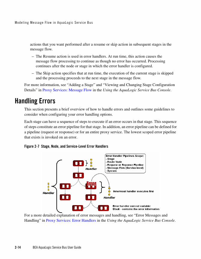
Handling ErrorsThis section presents a brief overview of how to handle errors and outlines some guidelines to consider when configuring your error handling options.
Each stage can have a sequence of steps to execute if an error occurs in that stage. This sequence of steps constitute an error pipeline for that stage. In addition, an error pipeline can be defined for a pipeline (request or response) or for an entire proxy service. The lowest scoped error pipeline that exists is invoked on an error.
Figure 2-7 Stage, Node, and Service-Level Error Handlers
For a more detailed explanation of error messages and handling, see “Error Messages and Handling” in Proxy Services: Error Handlers in the Using the AquaLogic Service Bus Console.

Hand l ing E r ro rs
BEA AquaLogic Service Bus User Guide 2-15
You can handle errors in the following ways:
Configure a test that checks if an assertion is true and use a reply action (with failure) in the request or response pipelines.
Catch and handle the errors at the stage level, route node level, or pipeline level. For more information, see “Adding Stage Error Handling”, “Adding Pipeline Error Handling”, and “Adding Error Handling for the Route Node” in Proxy Services: Error Handlers in Using the AquaLogic Service Bus Console.
Catch and handle the errors at the service level. For more information, see “Adding Error Handling for the Proxy Service” in Proxy Services: Error Handlers in Using the AquaLogic Service Bus Console.
Let the system error handler handle the error. The system error handler handles the error in the event that the error is not handled by a stage or a service level handler.
A predefined context variable (the fault variable) is used to hold information about any error that occurs during message processing. When an error occurs, this variable is populated with information before the appropriate error handler is invoked. The fault variable is defined only in error handler pipelines and is not set in request and response pipelines, or in route or branch nodes. To learn more about $fault, see “Predefined Context Variables” in Message Context in Using the AquaLogic Service Bus Console.
In general, it is easier to handle specific errors at the lowest level of the message flow and use higher level error handlers for more general default processing of errors that are not handled at the lower levels. It is good practice to explicitly handle anticipated errors in the pipelines and allow the service-level handler to handle unanticipated errors. However, if you decide to handle anticipated errors in the pipelines, you can only handle WS-Security related errors at the service level.
Generating the Error Message, Reporting, and ReplyingIn the event of errors for request/response type inbound messages, it is often necessary to generate a message that is sent back to the originator outlining the reason why an error occurred. You can accomplish this using a reply with failure action after configuring the message context variables with the response you want to send. For example, when a HTTP message fails, Reply with Failure generates the HTTP 500 status. When a JMS message fails, Reply with Failure sets the JMS_BEA_Error property to true. The AquaLogic Service Bus error actions are discussed in “Error Messages and Handling” in Proxy Services: Error Handlers in the Using the AquaLogic Service Bus Console.

Mode l ing Message F l ow in AquaLog ic Ser v ice Bus
2-16 BEA AquaLogic Service Bus User Guide
An error handling pipeline is invoked if a service invoked by a proxy service returns a SOAP fault or transport error. Any received SOAP fault is stored in $body, so if a Reply with Failure is executed without modifying $body, the original SOAP fault is returned to the client that invoked the service. If a reply action is not configured, the system error handler generates a new SOAP fault message. The proxy service recognizes that a SOAP fault is returned because a HTTP error status is set, or the JMS property SERVER_Error is set to true.
Some use cases require error reporting. You can use the report action in these situations. For example, consider a scenario in which the request pipeline reports a message for tracking purposes, but the service invoked by the route node fails after the reporting action. In this case, the reporting system logged the message, but there is no guarantee that the message was processed successfully, only that the message was successfully received.
You can use the AquaLogic Service Bus Console to track the message to obtain an accurate picture of the message flow. This allows you to view the original reported message indicating the message was submitted for processing, and also the subsequent reported error indicating that the message was not processed correctly. To learn how to configure a Report action and use the data reported at run time, see Proxy Services: Actions in Using the AquaLogic Service Bus Console.
ExampleThis example shows how the Report and Reply actions can be configured in error handlers. The message flow shown in Figure 2-2 includes an error handler on the validate loan application stage. The error handler in this case is a simple message flow with a single stage configured—it is represented in the AquaLogic Service Bus Console as shown in the following figure:
Figure 2-8 Error Handler Message Flow

Hand l ing E r ro rs
BEA AquaLogic Service Bus User Guide 2-17
The stage is, in turn, configured with actions (Replace, Report, and Reply) as shown in the following figure:
Figure 2-9 Actions in Stage Error Handler
The actions specify the behavior of the stage error handler as follows:
Replace—to specify that the contents of a specified element of the body variable are replaced with the contents of the fault context variable. The body variable element is specified by an XPath expression. The contents are replaced with the value returned by an XQuery expression—in this case $fault/ctx:reason/text()
Report—AquaLogic Service Bus provides the capability to deliver message data to one or more reporting providers. Message data can be captured from the body of the message or from any other variables associated with the message, such as header or inbound variables. You can use the message delivered to the reporting provider for functions such as tracking messages or regulatory auditing. This Report action results in report messages being written to the AquaLogic Service Bus Reporting Data Stream in the case that this error handler is invoked. The JMS Reporting Provider reports the messages on the AquaLogic Service Bus Dashboard.
In this case, in the event of an error, the contents of the fault context variable are reported. errorCode is the key name, and the key value is extracted from the fault variable using the following XPath expression: ./ctx:errorCode. Key/value pairs are the key identifiers that are used to identify these messages in the Dashboard at run time.
To learn how to configure a Report action and use the data reported at run time, see Proxy Services: Actions in Using the AquaLogic Service Bus Console.

Mode l ing Message F l ow in AquaLog ic Ser v ice Bus
2-18 BEA AquaLogic Service Bus User Guide
Reply—In this case, the reply is With Failure. At run time, an immediate reply is sent to the invoker of the loanGateway3 proxy service (see Figure 2-2) indicating that the message had a fault.
For configuration information, see “Error Messages and Handling” in Proxy Services: Error Handlers in Using the AquaLogic Service Bus Console.
Selecting a Service TypeAquaLogic Service Bus supports a variety of service types that range from conventional Web services (using XML or SOAP bindings in WSDLs) to non-XML or generic services. This section provides guidelines on selecting a service type.
AquaLogic Service Bus service types include:
SOAP Services—SOAP services receive and respond with SOAP messages. SOAP messages are constructed by wrapping the contents of the header and body variables inside a <soap:Envelope> element.
XML Services (Non SOAP)—The messages to XML-based services are XML, but can be of any type allowed by the proxy service configuration.
Messaging Services—Messaging services are those that can receive messages of one data type and respond with messages of a different data type. The supported data types include XML, MFL, text, and untyped binary.
Note: All service types can send and receive attachments using MIME.
The following table shows the service types and the transports on which they are supported by AquaLogic Service Bus.
Table 2-3 Supported Service Types and Transports
Service Type Transport Protocols
SOAP or XML WSDL JMS
HTTP(S)
SOAP (no WSDL) JMS
HTTP(S)

Selec t ing a Se rv ice T ype
BEA AquaLogic Service Bus User Guide 2-19
Use a WSDL to Define a ServiceIf a service has a well defined Web Services Description Language (WSDL) interface, it is recommended, although not required, that you use the WDSL to define the service. For more WSDL information, see WSDLs in Using the AquaLogic Service Bus Console.
The benefits of using a WSDL in this situation include:
The system can provide metrics for each operation in a WSDL.
Operational branching is possible in the pipeline. For more information, see “Branching in Message Flows” on page 2-8.
The SOAPAction header is automatically populated for services invoked by a proxy service.
A WSDL is required for services using WS-Security. WS-Policies are attached to WSDLs. For more information, see WS-Polices in Using the AquaLogic Service Bus Console.
The system supports the <url>?WSDL syntax, which allows you to dynamically obtain the WSDL of a HTTP proxy service. This is useful for a number of SOAP client generation tools including BEA WebLogic Workshop.
In the XQuery and XPath editors and condition builders, it is easy to manipulate the body content variable ($body) because the editor provides a default mapping of $body to the
XML (no WSDL)1 HTTP(S)
JMS
File
FTP
Messaging Type (Binary, Text, MFL, XML)
HTTP(S)
JMS
File
FTP
1. HTTP GET is only supported for XML with no WSDL.
Service Type Transport Protocols

Mode l ing Message F l ow in AquaLog ic Ser v ice Bus
2-20 BEA AquaLogic Service Bus User Guide
request message in the WSDL of a proxy service. For more information, see Message Context in Using the AquaLogic Service Bus Console.
Note: The run-time contents of $body for a specific action can be different from the default mapping displayed in the editor. This is because AquaLogic Service Bus is not a programming language in which typed variables are declared and used. Instead, variables are untyped and are created dynamically at run time when a value is assigned. In addition, the type of the variable is the type that is implied by its contents at any point in the message flow. To enable you to easily create XQuery and XPath expressions, the design time editor allows you to map the type for a given variable by mapping the variable to the type in the editor. To learn about using the XQuery and XPath editor to create expressions, see “Variable Structures” on page 2-31.
Choosing a WSDL Port or Binding?If you use a WSDL service type, it is useful to bind the service to a WSDL port instead of a binding because:
If the service is bound to port X in the template WSDL, then port X is also defined in the generated WSDL. Any other ports defined in the template WSDL are not included in the generated WSDL. Furthermore, if you base the proxy service on a WSDL port, the generated WSDL uses that port name and preserves any WS-Policies associated with that port.
(The template WSDL is the WSDL for the service upon which you based your proxy service; the generated WSDL is the WSDL created for the new proxy service.)
If the service is bound to binding Y in the template WSDL, the generated WSDL defines one service and port (<service-name>QSService and <port-name>QSPort). None of the ports defined in the template WSDL are included in the generated WSDL.
You can get the WSDL for an HTTP(S)-based proxy service by entering the URL for the service appended with ?WSDL in your browser’s Address field.
In the WSDL generated with the ?WSDL syntax, the port name is preserved if the proxy service is bound to a port on the WSDL and the URL accurately reflects the URL of the proxy service. This can be important to some client generation tools. The URL in the WSDL port bound to the service is not used during service definition, except to populate the URL in the WSDL port as the default URL for a business service. You can overwrite the transport type and transport URL in the transport configuration UI for the service definition.
Any WS-Security policies at the port level apply. For more information, see “Overview of Proxy Services” in Proxy Services in Using the AquaLogic Service Bus Console.

Dynamic Rout ing
BEA AquaLogic Service Bus User Guide 2-21
Any SOAP or Any XML Service TypesIf you want to expose one port to clients for a variety of enterprise applications, use Any SOAP or Any XML service types.
Messaging Service TypeIf one of the request or response messages is non-XML, you must use the messaging service type.
AquaLogic Service Bus does not automatically perform “mistunderstand” SOAP header checking. However, you can use XQuery conditional expressions and validate actions to explicitly perform this type of check. For more information on the validate action, see “Validate” in Proxy Services: Actions in the Using the AquaLogic Service Bus Console. For more information on XQuery conditional expressions, see “Using the XQuery Condition Editor” in Proxy Services: Editors in the Using the AquaLogic Service Bus Console.
AquaLogic Service Bus does not automatically validate the message sent or received against the service interface definition, whether it is a WSDL definition or a messaging interface definition. However, you can configure a validate action and use XQuery conditional expressions to perform validation checks explicitly in the message flow.
For more information on service types, see “Overview of Proxy Services” in Proxy Services in the Using the AquaLogic Service Bus Console.
Dynamic RoutingFor a scenario in which you are designing a proxy service but you do not know the concrete service to invoke from that service, but you do know the shape of the interface, you can specify the service to be invoked directly or indirectly in the request message.
Note: The shape of a service refers to the abstract interface: namely message types, port types, and binding, and excludes the concrete interface. The concrete interface is the transport URL at which the service is located.
In this case, register a business service with the right shape (the transport URL does not matter). You can override the service URL by configuring $outbound with the URL of the service to invoke. In this way, the URL can be supplied at run time and the need to know it when you design and configure your service is eliminated.

Mode l ing Message F l ow in AquaLog ic Ser v ice Bus
2-22 BEA AquaLogic Service Bus User Guide
Message ContextThe message context is a set of variables that hold message context and information about messages as they are routed through the AquaLogic Service Bus. Together, the header, body, and attachments variables, (referenced as $header, $body and $attachments in XQuery statements) represent the message as it flows through AquaLogic Service Bus. The canonical form of the message is SOAP. Even if the service type is not SOAP, the message appears as SOAP in the AquaLogic Service Bus message context.
$header contains a SOAP Header element, $body contains a SOAP Body element, and $attachments contains a wrapper element called attachments with one child attachment element per attachment. The attachment element has a body element with the actual attachment.
When a message is received by a proxy service, the message contents are used to initialize the header, body, and attachments variables. For SOAP services, the Header and Body elements are taken directly from the envelope of the received SOAP message and assigned to $header and $body respectively. For non-SOAP services, the entire message contents are typically wrapped in a Body element and assigned to $body, and an empty Header element is assigned to $header.
Binary and MFL messages are initialized differently. For MFL messages, the equivalent XML document is injected into the Body element that is assigned to $body. For binary messages, the message data is stored internally and a piece of reference XML is injected into the Body element that is assigned to $body. The reference XML looks like <binary-content ref="..."/>, where "..." contains an unique identifier assigned by the proxy.
The message context is defined by an XML Schema. You typically use XQuery expressions to manipulate the context variables in the message flow that defines a proxy service.
The predefined context variables provided by AquaLogic Service Bus can be grouped into the following types:
Message-related variables
Inbound and outbound variables
Operation variable
Fault variable
For information about the predefined context variables, see “Predefined Context Variables” in Message Context in Using the AquaLogic Service Bus Console.
The message payload is contained in the body variable. The decision about which variable’s content to include in an outgoing message is made at the point at which a message is dispatched

Message Contex t
BEA AquaLogic Service Bus User Guide 2-23
from AquaLogic Service Bus. That determination is dependent upon whether the target endpoint is expecting a SOAP or a non-SOAP message:
If the message is binary, any text or XML content inside the Body element in $body is sent.
For MFL messages, the Body element in $body contains the XML equivalent of the MFL document.
For text messages, the Body element in $body contains the text. For text attachments, the body element in $attachments contains the text. If the contents are XML instead of simple text, the XML is sent as a text message.
For XML messages, the Body element in $body contains the XML. For XML attachments, the body element in $attachments contains the XML.
SOAP messages are constructed by wrapping the contents of the header and body variables inside a <soap:Envelope> element. If the body variable contains a piece of reference XML, it is sent as is—in other words, the referenced content is not substituted into the message.
For non-SOAP services, if the Body element of $body contains a binary-content element, then the referenced content stored internally is sent ‘as is’, regardless of the target service type.
For more information, see Message Context in the Using the AquaLogic Service Bus Console.
The types for the message context variables are defined by the message context schema (MessageContext.xsd). When working with the message context variables in the BEA XQuery Mapper, you need to reference MessageContext.xsd and the transport-specific schemas, which are available in a JAR file at the following location in your AquaLogic Service Bus installation:
BEA_HOME\weblogic90\servicebus\lib\sb-schemas.jar
where BEA_HOME represents the directory in which you installed AquaLogic Service Bus.
To learn about the message context schema and the transport specific schemas, see “Message Context Schema” in Message Context in the Using the AquaLogic Service Bus Console.

Mode l ing Message F l ow in AquaLog ic Ser v ice Bus
2-24 BEA AquaLogic Service Bus User Guide
Key Context Manipulation FactsConsider the following guidelines when you want to inspect or alter the message context:
In an XQuery expression, the root element in a variable is not present in the path when referring to an element in that variable. For example, the following XQuery expression obtains the Content-Description of the first attachment in a message:
$attachments/ctx:attachment[1]/ctx:Content-Description
To obtain the second attachment that contains, for example, a purchase order:
$attachments/ctx:attachment[2]/ctx:body/*
A context variable is either empty or it contains a single XML element or string value. However, an XQuery expression often returns a sequence. When you use an XQuery expression to assign a value to a variable, only the first element in the sequence returned by the expression is stored as the variable value. For example, if you want to assign the value of a WS-Addressing Message ID from a SOAP header (assuming there is one in the header) to a variable named idvar, the assign action specification is:
assign data($header/wsa:MessageID) to variable idvar.
Note: In this case, if two WS-Addressing MessageID headers exist, the idvar variable will be assigned the value of the first one.
The variables $header, $body, and $attachments are never empty. However, $header can contain an empty SOAP Header element, $body can contain an empty SOAP Body element, and $attachments can contain an empty attachment element.
For many of the cases in which you use a transformation resource (XSLT or XQuery), the transformation resource is defined to transform the document in the SOAP body of a message. To make this transformation case easy and efficient, the input parameter to the transformation can be an XQuery expression. For example, you can use the following XQuery expression to feed the business document in the Body element of a message ($body) as input to a transformation:
$body/* [1]
The result of the transformation can be put back in $body with a Replace action (replace the content of $body, which means the content of the Body element). For more information, see XQuery Transformations and XSL Transformations in Using the AquaLogic Service Bus Console.
In addition to inserting or replacing a single element, you can also insert or replace a selected sequence of elements using an insert or replace action. You can configure an

RPC and Document S ty l e SOAP
BEA AquaLogic Service Bus User Guide 2-25
XQuery expression to return a sequence of elements. For example, you can use insert and replace actions to copy a set of transport headers from $inbound to $outbound. For information on adding an action, see “Adding an Action” in Proxy Services: Actions in the Using the AquaLogic Service Bus Console. For an example, see “Copying JMS Properties From Inbound to Outbound” on page 2-25.
Copying JMS Properties From Inbound to OutboundAquaLogic Service Bus assumes that the interface of the proxy services and the invoked business service may be different. Therefore, it does not propagate any information (like the transport headers and JMS properties) from the inbound variable to the outbound variable.
The transport headers for the proxy service’s request and response messages are in $inbound and the transport headers for the invoked business service’s request and response are in $outbound.
For example, the following XQuery expression can be used in a case where the user-defined JMS properties for a one way message (an invocation with no response) need to be copied from inbound to outbound:
Use the Transport Headers action to set
$inbound/ctx:transport/ctx:request/tp:headers/tp:user-header
as the first child of:
./ctx:transport/ctx:request/tp:headers
in the outbound variable.
To learn how to configure the Transport Header action in the AquaLogic Service Bus Console, see “Transport Headers” in Proxy Services: Actions in the Using the AquaLogic Service Bus Console.
RPC and Document Style SOAPAquaLogic Service Bus supports Remote Procedure Calls (RPC) style SOAP and document style SOAP. For more information, see:
RPC Web Services
Document Style SOAP

Mode l ing Message F l ow in AquaLog ic Ser v ice Bus
2-26 BEA AquaLogic Service Bus User Guide
RPC Web ServicesYou can configure proxy services as RPC style proxy services and configure business services as RPC style business services.
The following listing provides an example of a WSDL for a sample RPC style Web service.
Listing 2-1 WSDL for a Sample RPC Style Web Service
<definitions name="Lookup"targetNamespace="http://example.com/lookup/service/defs"xmlns:tns="http://example.com/lookup/service/defs"xmlns:xs="http://www.w3.org/2001/XMLSchema"xmlns:docs="http://example.com/lookup/docs"xmlns:soap="http://schemas.xmlsoap.org/wsdl/soap/"xmlns="http://schemas.xmlsoap.org/wsdl/"><types>
<xs:schema targetNamespace="http://example.com/lookup/docs" elementFormDefault="qualified">
<xs:complexType name="RequestDoc"><xs:sequence>
<xs:element name="PurchaseOrg" type="xs:string"/></xs:sequence>
</xs:complexType><xs:complexType name="ResponseDoc"><xs:sequence>
<xs:element name="LegacyBoolean" type="xs:boolean"/></xs:sequence>
</xs:complexType></xs:schema>
</types><message name="lookupReq">
<part name="request" type="docs:RequestDoc"/></message><message name="lookupResp">
<part name="result" type="docs:ResponseDoc"/></message><portType name="LookupPortType">
<operation name="lookup"><input message="tns:lookupReq"/><output message="tns:lookupResp"/>
</operation></portType><binding name="LookupBinding" type="tns:LookupPortType">
<soap:binding style="rpc" transport="http://schemas.xmlsoap.org/soap/http"/>

RPC and Document S ty l e SOAP
BEA AquaLogic Service Bus User Guide 2-27
<operation name="lookup"><soap:operation/><input><soap:body use="literal"
namespace="http://example.com/lookup/service"/></input><output><soap:body use="literal"
namespace="http://example.com/lookup/service"/></output>
</operation></binding>
</definitions>
The service described in the preceding listing includes an operation (equivalent to a method in a java class) called lookup. The binding indicates that this is a SOAP RPC Web service. In other words, the Web service’s operation receives a set of request parameters and returns a set of response parameters. The lookup operation has a parameter called request and a return parameter called result. The namespace of the operation in the binding is:
http://example.com/lookup/service
When the WSDL shown in Listing 2-2 is used for a request, the value of the body variable ($body) that the SOAP RPC proxy service obtains is displayed in the following listing.
Note: Namespace declarations have been removed from the XML in the listings that follow for the sake of clarity.
Listing 2-2 Body Variable Value
<soap-env:Body>
<ns:lookup>
<request>
<req:PurchaseOrg>BEA Systems</req:PurchaseOrg>
</request>
</ns:lookup>
<soap-env:Body>
Mode l ing Message F l ow in AquaLog ic Ser v ice Bus
2-28 BEA AquaLogic Service Bus User Guide
Where soap-env is the predefined SOAP name space, ns is the operation namespace (<http://example.com/lookup/service>) and, req is the namespace of the PurchaseOrg element (<http://example.com/lookup/docs>).
If the business service to which the proxy service routes the messages uses the WSDL shown in Listing 2-2, the value for the body variable ($body), shown in Listing 2-3, is the value of the body variable ($body) from the proxy service.
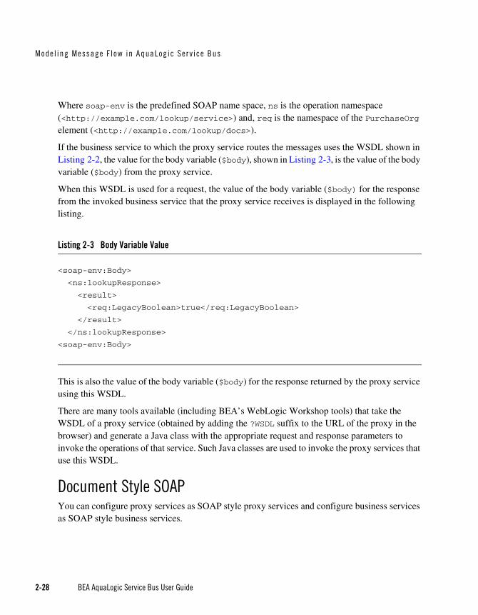
When this WSDL is used for a request, the value of the body variable ($body) for the response from the invoked business service that the proxy service receives is displayed in the following listing.
Listing 2-3 Body Variable Value
<soap-env:Body>
<ns:lookupResponse>
<result>
<req:LegacyBoolean>true</req:LegacyBoolean>
</result>
</ns:lookupResponse>
<soap-env:Body>
This is also the value of the body variable ($body) for the response returned by the proxy service using this WSDL.
There are many tools available (including BEA’s WebLogic Workshop tools) that take the WSDL of a proxy service (obtained by adding the ?WSDL suffix to the URL of the proxy in the browser) and generate a Java class with the appropriate request and response parameters to invoke the operations of that service. Such Java classes are used to invoke the proxy services that use this WSDL.
Document Style SOAPYou can configure proxy services as SOAP style proxy services and configure business services as SOAP style business services.

RPC and Document S ty l e SOAP
BEA AquaLogic Service Bus User Guide 2-29
The following listing provides an example of a WSDL for a sample document style Web service.
Listing 2-4 WSDL for a Sample Document Style Web Service
<definitions name="Lookup"targetNamespace="http://example.com/lookup/service/defs"xmlns:tns="http://example.com/lookup/service/defs"xmlns:xs="http://www.w3.org/2001/XMLSchema"xmlns:docs="http://example.com/lookup/docs"xmlns:soap="http://schemas.xmlsoap.org/wsdl/soap/"xmlns="http://schemas.xmlsoap.org/wsdl/"><types>
<xs:schema targetNamespace="http://example.com/lookup/docs" elementFormDefault="qualified">
<xs:element name="PurchaseOrg" type="xs:string"/><xs:element name="LegacyBoolean" type="xs:boolean"/>
</xs:schema></types><message name="lookupReq">
<part name="request" element="docs:PurchaseOrg"/></message><message name="lookupResp">
<part name="result" element="docs:LegacyBoolean"/></message><portType name="LookupPortType">
<operation name="lookup"><input message="tns:lookupReq"/><output message="tns:lookupResp"/>
</operation></portType><binding name="LookupBinding" type="tns:LookupPortType">
<soap:binding style="document" transport="http://schemas.xmlsoap.org/soap/http"/>
<operation name="lookup"><soap:operation/><input><soap:body use="literal" />
</input><output><soap:body use="literal"/>
</output></operation>
</binding></definitions>

Mode l ing Message F l ow in AquaLog ic Ser v ice Bus
2-30 BEA AquaLogic Service Bus User Guide
The service has an operation (equivalent to a method in a Java class) called lookup. The binding indicates that this is a SOAP document style Web service.
When the WSDL shown in the preceding listing is used for a request, the value of the body variable ($body) that the document style proxy service obtains is displayed in the following listing.
Listing 2-5 Body Variable Value
<soap-env:Body>
<req:PurchaseOrg>BEA Systems</req:PurchaseOrg>
<soap-env:Body>
Where soap-env is the predefined SOAP name space and req is the namespace of the PurchaseOrg element (<http://example.com/lookup/docs>).
If the business service to which the proxy service is routing uses the above WSDL, the value for the body variable ($body) given above, is the value of the body variable ($body) from the proxy service.
The value of the body variable ($body) for the response from the invoked business service that the proxy service receives is displayed in the following listing.
Listing 2-6 Body Variable Value
<soap-env:Body>
<req:LegacyBoolean>true</req:LegacyBoolean>
<soap-env:Body>
This is also the value of the body variable ($body) for the response returned by the proxy service using this WSDL.
There are many tools available (including BEA’s WebLogic Workshop tools) that take the WSDL of a proxy service (obtained by adding the ?WSDL suffix to the URL of the proxy service in the browser) and generate a Java class with the appropriate request and response parameters to invoke the operations of the service. This Java class can be used to invoke the proxy service that uses this WSDL.

Var iab le S t ructur es
BEA AquaLogic Service Bus User Guide 2-31
Variable StructuresThis section includes the following topics:
Using the Inline XQuery Expression Editor
Using Variable Structures
Using Variable Structure Mappings
Using the Inline XQuery Expression EditorAquaLogic Service Bus allows you to import XQueries that have been created with an external tool such as the BEA XQuery Mapper. You can use these XQueries anywhere in the proxy service message flow by binding the XQuery resource input to an Inline XQuery, and binding the XQuery resource output to an action that uses the result as the action input; for example, the Assign, Replace, or Insert actions.
However, you can enter the XQuery inline as part of the action definition instead of entering the XQuery as a resource. You can also use Inline XQueries for the condition in an If...Then... action.
You typically use the Inline XQuery Expression Editor to enter simple XQueries that consist of the following:
Fragments of XML with embedded XQueries.
Simple variable paths along the child axis.
Note: For more complex XQueries, we recommend that you use the XQuery Mapper, especially if you are not familiar with XQuery.
Examples of good uses of Inline XQueries are:
Extract or access a business document or RPC parameter from the SOAP envelope elements in $header or $body.
Extract or access an attachment document in $attachments.
Set up the parameters of a Service Callout action by extracting it from the SOAP envelope.
Fold the result parameter of a Service Callout action into the SOAP envelope.
Extract a sequence from the SOAP envelope to drive a for loop.
Update an item in the sequence in a for loop with an Update action.

Mode l ing Message F l ow in AquaLog ic Ser v ice Bus
2-32 BEA AquaLogic Service Bus User Guide
Note: You can use the Inline XQuery Expression Editor to create variable structures. To learn more, see “Using Variable Structures” on page 2-32.
Using Variable StructuresYou can use the Inline XQuery Expression Editor to create variable structures, which you can use to attach or define the structure of a given variable for design purposes (for example, an easy-to-create XPath, understanding what the variable is about, the ability to browse the structure in the Console rather than viewing the XML Schema).
Note: It is not necessary to create variable structures for your runtime to work.
In a typical programming language, variables are statically scoped and their name and type is explicitly declared. The variable can be accessed anywhere within the static scope.
In AquaLogic Service Bus, some predefined variables do exist, but you can also dynamically create variables by assigning a value to them. When a value is assigned to a variable, the variable can be accessed anywhere in the proxy service message flow. The variable type is not declared but the type is essentially the underlying type of the value it contains at any point in time.
When you use the Inline XQuery Expression Editor, the XQuery has zero or more inputs and one output. Because you can display the structure of the inputs and the structure of the output visually in the Expression Editor itself, you do not need to open the XML Schema or WSDL resources to see their structure when you create the Inline XQuery. The graphical structure display also enables you to drag and drop simple variable paths along the child axis without predicates into the XQuery being composed.
Each variable structure mapping entry has a label and maps a variable or variable path to one or more structures. The scope of these mappings is the stage or route node. Because variables are not statically typed, a variable can have different structures at different points (or at the same point) in the stage or route node. Therefore, you can map a variable to multiple structures, each with a different label. To view the structure, you can select the corresponding label with a drop-down list.
Note: You can also create variable structure mappings in the Inline XPath Expression Editor. However, although the variable is mapped to a structure, the XPaths generated when you select from the structure are relative XPaths relative to the variable. An example of a relative XPath is ./ctx:attachment/ctx:body. However, the mapping used to generate this XPath would map $attachments.

Var iab le S t ructur es
BEA AquaLogic Service Bus User Guide 2-33
Using Variable Structure MappingsThis section includes the following topics:
Sample WSDL
Creating the Resources You Need for the Examples
Example 1: Selecting a Predefined Variable Structure
Example 2: Creating a Variable Structure that Maps a Variable to a Type
Example 3: Creating a Variable Structure that Maps a Variable to an Element
Example 4: Creating a Variable Structure that Maps a Variable to a Child Element
Example 5: Creating a Variable Structure that Maps a Variable to a Business Service
Example 6: Creating a Variable Structure that Maps a Child Element to Another Child Element
Sample WSDLThis sample WSDL is used in most of the examples in this section. You need to save this WSDL as a resource in your configuration. To learn more, see Creating the Resources You Need for the Examples.
Listing 2-7 Sample WSDL
<definitions name="samplewsdl" targetNamespace="http://example.org" xmlns="http://schemas.xmlsoap.org/wsdl/" xmlns:s0="http://www.bea.com" xmlns:s1="http://example.org" xmlns:soap="http://schemas.xmlsoap.org/wsdl/soap/">
<types> <xs:schema
attributeFormDefault="unqualified" elementFormDefault="qualified" targetNamespace="http://www.bea.com" xmlns:xs="http://www.w3.org/2001/XMLSchema"> <xs:element name="PO" type="s0:POType"/><xs:complexType name="POType"><xs:all>
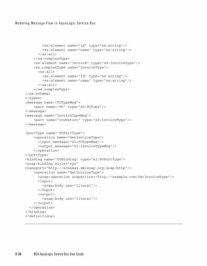
Mode l ing Message F l ow in AquaLog ic Ser v ice Bus
2-34 BEA AquaLogic Service Bus User Guide
<xs:element name="id" type="xs:string"/><xs:element name="name" type="xs:string"/>
</xs:all></xs:complexType><xs:element name="Invoice" type="s0:InvoiceType"/><xs:complexType name="InvoiceType"><xs:all><xs:element name="id" type="xs:string"/><xs:element name="name" type="xs:string"/>
</xs:all></xs:complexType>
</xs:schema></types><message name="POTypeMsg">
<part name="PO" type="s0:POType"/></message><message name="InvoiceTypeMsg">
<part name="InvReturn" type="s0:InvoiceType"/></message>
<portType name="POPortType"><operation name="GetInvoiceType"><input message="s1:POTypeMsg"/><output message="s1:InvoiceTypeMsg"/>
</operation></portType><binding name="POBinding" type="s1:POPortType"><soap:binding style="rpc" transport="http://schemas.xmlsoap.org/soap/http"/>
<operation name="GetInvoiceType"><soap:operation soapAction="http://example.com/GetInvoiceType"/><input><soap:body use="literal"/>
</input><output><soap:body use="literal"/>
</output></operation>
</binding></definitions>

Var iab le S t ructur es
BEA AquaLogic Service Bus User Guide 2-35
Creating the Resources You Need for the ExamplesTo make use of the examples that follow, you need to save the sample WSDL as a resource in your configuration, and you need to create the sample business and proxy services that use the sample WSDL.
The tasks in this procedure include:
To Save the WSDL as a Resource
To Create a Proxy Service that Uses the Sample WSDL
To Build Message Flow for the Sample Proxy Service
To Create a Business Service that Uses the Sample WSDL
To Save the WSDL as a Resource
1. If you have not already done so, from the left navigation pane in the AquaLogic Service Bus Console, under Change Center, click Create to create a new session for making changes to the current configuration.
2. From the left navigation pane, select Project Explorer. The Project View page is displayed.
3. Select the project to which you want to add the WSDL.
4. From the Project View page, in the Create Resource field, select WSDL from under Interface. The Create a New WSDL Resource page is displayed.
5. In the Resource Name field, enter SampleWSDL. This is a required field.
6. In the WSDL field, copy and paste the text from the sample WSDL into this field.
Note: This is a required field.
7. To save the WSDL, click Save. The new WSDL SampleWSDL is included in the list of resources and is saved in the current session. You must now create a proxy service that uses this WSDL—continue in To Create a Proxy Service that Uses the Sample WSDL.
To Create a Proxy Service that Uses the Sample WSDL
1. From the left navigation pane, select Project Explorer. The Project View page is displayed.
2. Select the project to which you want to add the proxy service.

Mode l ing Message F l ow in AquaLog ic Ser v ice Bus
2-36 BEA AquaLogic Service Bus User Guide
3. From the Project View page, in the Create Resource field, select Proxy Service from under Service. The Edit a Proxy Service - General Configuration page is displayed.
4. In the Service Name field, enter ProxywithSampleWSDL. This is a required field.
5. In the Service Type field, which defines the types and packaging of the messages exchanged by the service, do the following:
a. Select WSDL binding from under Create a New Service.
b. Click Browse. The WSDL Browser is displayed.
c. Select SampleWSDL, then select POBinding in the Select WSDL Definitions pane.
d. Click Submit.
6. Use the defaults for all other fields on the General Configuration page, then click Next.
7. Use the defaults for all fields on the Transport Configuration pages, then click Next.
8. On the Operation Selection Configuration page, make sure SOAP Body Type is selected in the Selection Algorithm field, then click Next.
9. Review the configuration data that you have entered for this proxy service, then click Save. The new proxy service ProxywithSampleWSDL is included in the list of resources and is saved in the current session. You must now build message flow for this proxy service—continue in To Build Message Flow for the Sample Proxy Service.
To Build Message Flow for the Sample Proxy Service
1. On the Project View page, in the Actions column, click the Edit Message Flow icon for the ProxywithSampleWSDL proxy service. The Edit Message Flow page is displayed.
2. Click the ProxywithSampleWSDL icon, then click Add Pipeline Pair. PipelinePairNode1 is displayed, which includes request and response pipelines.
3. Click the request pipeline, then click Add Stage. The stage stage1 is displayed.
4. Click Save. The basic message flow is created for the ProxywithSampleWSDL proxy service.
When you work with the examples, you must edit the stage to access the Edit Stage Configuration page, then add an action that uses an expression to access the XQuery Expression Editor page. First, you must create a business service that uses SampleWSDL—continue in To Create a Business Service that Uses the Sample WSDL.

Var iab le S t ructur es
BEA AquaLogic Service Bus User Guide 2-37
To Create a Business Service that Uses the Sample WSDL
1. From the left navigation pane, select Project Explorer. The Project View page is displayed.
2. Select the project to which you want to add the business service.
3. From the Project View page, in the Create Resource field, select Business Service from under Service. The Edit a Business Service - General Configuration page is displayed.
4. In the Service Name field, enter BusinesswithSampleWSDL. This is a required field.
5. In the Service Type field, which defines the types and packaging of the messages exchanged by the service, do the following:
a. Select WSDL binding from under Create a New Service.
b. Click Browse. The WSDL Browser is displayed.
c. Select SampleWSDL, then select POBinding in the Select WSDL Definitions pane.
d. Click Submit.
6. Use the defaults for all other fields on the General Configuration page, then click Next.
7. Use the defaults for all fields on the Transport Configuration and SOAP Binding Configuration pages, then click Next.
8. Review the configuration data that you have entered for this business service, then click Save. The new business service BusinesswithSampleWSDL is included in the list of resources and is saved in the current session.
9. From the left navigation pane, click Activate under Change Center. The session ends and the configuration is deployed to run time. You are now ready to use the examples—continue in Example 1: Selecting a Predefined Variable Structure.
Example 1: Selecting a Predefined Variable StructureSuppose the proxy service ProxyWithSampleWSDL has a service type WSDL binding that uses the binding POBinding from SampleWSDL.
In this example, the proxy service message flow needs to know the structure of the message to manipulate it. To achieve this, AquaLogic Service Bus automatically provides a predefined structure that maps the body variable to the SOAP body for all the messages in the interface. This predefined structure mapping is labelled body.
Note: This predefined structure is also supported for messaging services with a typed interface.

Mode l ing Message F l ow in AquaLog ic Ser v ice Bus
2-38 BEA AquaLogic Service Bus User Guide
To Select a Predefined Variable Structure
In the Variable Structures panel on the XQuery Expression Editor page, select body from the drop-down list of built-in structures.
The variable structure body is displayed as follows:
Figure 2-10 Variable Structures—body
Example 2: Creating a Variable Structure that Maps a Variable to a TypeSuppose the proxy service ProxyWithSampleWSDL invokes a service callout to the business service BusinessWithSampleWSDL, which also has a service type WSDL binding that uses the binding POBinding from SampleWSDL. The operation GetInvoiceType is invoked.
In this example, the message flow needs to know the structure of the response parameter to manipulate it. To achieve this, you can create a new variable structure that maps the response parameter variable to the type InvoiceType.
To Map a Variable to a Type
1. In the Variable Structures panel, click Add New Structure. Additional fields are displayed as follows:

Var iab le S t ructur es
BEA AquaLogic Service Bus User Guide 2-39
Figure 2-11 Variable Structures—Add a New Structure
2. Make sure XML Type is selected.
3. In the Structure Label field, enter InvoiceType as the display name for the variable structure you want to create. This display name enables you to give a meaningful name to the structure so you can recognize it at design time but it has no impact at run time.
4. In the Structure Path field, enter $InvoiceType as the path of the variable structure at run time.
5. To select the type InvoiceType, do the following:
a. Under the Type field, select the appropriate radio button, then select WSDL Type.
b. Click Browse. The WSDL Browser is displayed.
c. In the WSDL Browser, select SampleWSDL, then select InvoiceType under Types in the Select WSDL Definitions pane.

Mode l ing Message F l ow in AquaLog ic Ser v ice Bus
2-40 BEA AquaLogic Service Bus User Guide
d. Click Submit. InvoiceType is displayed under your selection WSDL Type.
6. Click Add. The new variable structure InvoiceType is included under XML Type in the drop-down list of variable structures.
The variable structure InvoiceType is displayed as follows:
Figure 2-12 Variable Structures—InvoiceType
Example 3: Creating a Variable Structure that Maps a Variable to an ElementSuppose a temporary variable has the element Invoice described in the SampleWSDL WSDL. In this example, the ProxyWithSampleWSDL message flow needs to access this variable. To achieve this, you can create a new variable structure that maps the variable to the element Invoice.
To Map a Variable to an Element
1. In the Variable Structures panel, click Add New Structure.
2. Make sure XML Type is selected.
3. In the Structure Label field, enter Invoice as the meaningful display name for the variable structure you want to create.
4. In the Structure Path field, enter $Invoice as the path of the variable structure at run time.
5. To select the element Invoice, do the following:
a. Under the Type field, make sure the appropriate radio button is selected, then select WSDL Element.
b. Click Browse. The WSDL Browser is displayed.
c. In the WSDL Browser, select SampleWSDL, then select Invoice under Elements in the Select WSDL Definitions pane.

Var iab le S t ructur es
BEA AquaLogic Service Bus User Guide 2-41
d. Click Submit. Invoice is displayed under your selection WSDL Element.
6. Click Add. The new variable structure Invoice is included under XML Type in the drop-down list of variable structures.
The variable structure Invoice is displayed as follows:
Figure 2-13 Variable Structures—Invoice
Example 4: Creating a Variable Structure that Maps a Variable to a Child ElementThe ProxyWithSampleWSDL proxy service routes to the document style Any SOAP business service that returns the Purchase Order in the SOAP body. In this example, the ProxyWithSampleWSDL proxy service message flow must then manipulate the response. To achieve this, you can create a new structure that maps the body variable to the PO element, and specify the PO element as a child element of the variable. You need to specify it as a child element because the body variable contains the SOAP Body element and the PO element is a child of the Body element.
To Map a Variable to a Child Element
1. In the Variable Structures panel, click Add New Structure.
2. Make sure XML Type is selected.
3. In the Structure Label field, enter body to PO as the meaningful display name for the variable stucture you want to create.
4. In the Structure Path field, enter $body as the path of the variable structure at run time.
5. To select the PO element, do the following:
a. Under the Type field, make sure the appropriate radio button is selected, then select WSDL Element.
b. Click Browse. The WSDL Browser is displayed.

Mode l ing Message F l ow in AquaLog ic Ser v ice Bus
2-42 BEA AquaLogic Service Bus User Guide
c. In the WSDL Browser, select SampleWSDL, then select PO under Elements in the Select WSDL Definitions pane.
d. Click Submit.
6. Select the Set as child checkbox to set the PO element as a child of the body to PO variable structure.
7. Click Add. The new variable structure body to PO is included under XML Type in the drop-down list of variable structures.
The variable structure body to PO is displayed as follows:
Figure 2-14 Variable Structures—body to PO
Example 5: Creating a Variable Structure that Maps a Variable to a Business ServiceThe ProxyWithSampleWSDL proxy service routes to the BusinessWithSampleWSDL business service, which also has a service type WSDL binding that uses the binding POBinding from SampleWSDL. In this example, the message flow must then manipulate the response. To achieve this, you can define a new structure that maps the body variable to the BusinessWithSampleWSDL business service. This results in a map of the body variable to the SOAP body for all the messages in the interface.
Note: This mapping is also supported for messaging services with a typed interface.
To Map a Variable to a Business Service
1. In the Variable Structures panel, click Add New Structure.
2. Select Service Interface.
3. In the Structure Label field, enter BusinessService as the meaningful display name for the variable structure.

Var iab le S t ructur es
BEA AquaLogic Service Bus User Guide 2-43
4. In the Structure Path field, $body is already set as the default. This is the path of the variable structure at run time.
5. To select the business service, do the following:
a. Under the Service field, click Browse. The Service Browser is displayed.
b. In the Service Browser, select the BusinessWithSampleWSDL business service, then click Submit. The business service is displayed under the Service field.
c. In the Operation field, select All.
6. Click Add. The new variable structure BusinessService is included under Service Interface in the drop-down list of variable structures.
The variable structure BusinessService is displayed as follows:
Figure 2-15 Variable Structures—BusinessService
Example 6: Creating a Variable Structure that Maps a Child Element to Another Child ElementSuppose you modify the SampleWSDL so that the ProxyWithSampleWSDL proxy service receives a single attachment. The attachment is a Purchase Order. In this example, the proxy service message flow must then manipulate the Purchase Order. To achieve this, you can define a new structure that maps the body element in $attachments to the PO element, which is specified as a child element. The body element is specified as a variable path of the form:
$attachments/ctx:attachment/ctx:body

Mode l ing Message F l ow in AquaLog ic Ser v ice Bus
2-44 BEA AquaLogic Service Bus User Guide
You can select and copy the body element from the predefined attachments structure, paste this element as the variable path to be mapped in the new mapping definition, then modify the pasted value to add the predicate.
To Map a Child Element to Another Child Element
1. In the Variable Structures panel, select attachments from the drop-down list of built-in structures.
The variable structure attachments is displayed as follows:
Figure 2-16 Variable Structures—attachments
2. Select the body child element in the attachments structure. The contents of body are displayed in the Property Inspector on the right side of the page:
$attachments/ctx:attachment/ctx:body
3. Copy the contents of the body element.
4. In the Variable Structures panel, click Add New Structure.
5. Make sure XML Type is selected.
6. In the Structure Label field, enter PO attachment as the meaningful display name for this variable structure.
7. In the Structure Path field, paste the contents of the body element:
$attachments/ctx:attachment/ctx:body
This is the path of the variable structure at run time.
8. To select the PO element, do the following:

Qual i t y o f Se rv ice
BEA AquaLogic Service Bus User Guide 2-45
a. Under the Type field, make sure the appropriate radio button is selected, then select WSDL Element.
b. Click Browse. The WSDL Browser is displayed.
c. In the WSDL Browser, select SampleWSDL, then select PO under Elements in the Select WSDL Definitions pane.
d. Click Submit.
9. Select the Set as child checkbox to set the PO element as a child of the body element.
10. Click Add. The new variable structure second attachment is included under XML Type in the drop-down list of variable structures.
11. If there can be multiple attachments, you’ll need to add an index to the reference when you use fields from this structured variable in your XQueries. For example, if you drag the PO field to the XQuery Text box, but the PO will be the second attachment, you’ll need to change the inserted value
$attachments/ctx:attachment/ctx:body/bea:PO/bea:id
to
$attachments/ctx:attachment[2]/ctx:body/bea:PO/bea:id
Quality of ServiceThis section includes the following topics:
Delivery Guarantees
Outbound Message Retries
Delivery GuaranteesBEA AquaLogic Service Bus supports reliable messaging. When messages are routed to another service from a route node, the default quality of service (QoS) element in $outbound is either exactly-once or best-effort. The value of the qualityOfService element in the outbound context variable provides AquaLogic Service Bus with a hint on the desired delivery behavior. The value of the qualityOfService element is used only for a proxy service’s outbound transport in the case of HTTP, HTTPS, or JMS transports.
The folllowing is the list of delivery guarantee types provided:

Mode l ing Message F l ow in AquaLog ic Ser v ice Bus
2-46 BEA AquaLogic Service Bus User Guide
Table 2-4 Delivery Guarantee Types
Delivery Reliability Description
Exactly once Exactly once means reliability is optimized. Exactly once delivery reliability is a hint, not a directive. When exactly once is specified, exactly once reliability is provided if possible.
The default value of the qualityOfService element is exactly-once for a Route Node action if the proxy service inbound transport is as follows:
• FTP
• File
• JMS/XA
At least once At least once delivery semantics are attempted if exactly once is not possible but the qualityOfService element is exactly-once.
Best effort Best effort delivery is performed if exactly once and at least once delivery semantics are not possible but the qualityOfService element is exactly-once.. Best effort means that performance or availability is optimized.
The default value of the qualityOfService element is best-effort for the following inbound transports:
• JMS/nonXA
• HTTP
• HTTPS
The default value of the qualityOfService element is best-effort for the following:
• Service callout action — always best-effort, not modifiable
• Publish action — defaults to best effort, modifiable
• Route action — defaults to $inbound QoS, modifiable
• Proxy service response message — always exactly once where applicable, not modifiable
Note: When the value of the qualityOfService element is best-effort for a Publish action, all errors are ignored. However, when the value of the qualityOfService element is best-effort for a Route Node action or a Service callout action, any error will raise an exception.

Qual i t y o f Se rv ice
BEA AquaLogic Service Bus User Guide 2-47
Overriding the Default Element AttributeYou can override the default qualityOfService element attribute for the following:
Route Node action
Publish action
Note: You cannot override the qualityOfService element attribute for a Service callout action.
To override the qualityOfService element attribute, you must set the qualityOfService in the outbound message context variable ($outbound). For more information, see “Message Context Schema” in Message Context in Using the AquaLogic Service Bus Console.
Delivery Guarantee RulesThe delivery guarantee supported when a proxy service publishes a message or routes a request to a business service depends on the following conditions:
The value of the qualityOfService element.
The inbound transport (and connection factory if applicable).
The outbound transport (and connection factory if applicable).
However, if the inbound proxy service is not JMS and the invoker is another proxy service, the inbound transport of the invoking proxy service is responsible for the delivery guarantee. This is because a proxy service that invokes another proxy service is optimized into a direct invocation if the transport of the invoked proxy service is not JMS. For more information on transport protocols, see “Adding a Proxy Service” and “Adding a Business Service” in Proxy Services in the Using the AquaLogic Service Bus Console.
Note: No delivery guarantee is provided for responses from a proxy service.
The following rules govern delivery guarantees:
Table 2-5 Delivery Guarantee Rules

Mode l ing Message F l ow in AquaLog ic Ser v ice Bus
2-48 BEA AquaLogic Service Bus User Guide
Note: To support at least once and exactly once delivery guarantees, you must exploit JMS transactions and configure a retry count and retry interval on the JMS queue to ensure the message is redelivered in the event of a server crash or a failure that is not handled in an error handler with a Reply or Resume action. File, FTP, and email transports also internally use a JMS/XA queue. The default retry count for a proxy service with a JMS/XA transport is 1. For a list of the default JMS queues created by AquaLogic Service Bus, see the BEA AquaLogic Service Bus Deployment Guide.
Here are some more delivery guarantee rules:
If the proxy service inbound transport is file, FTP, email, or JMS/XA, the request flow work is performed in a transaction.
– When the qualityOfService element is set to exactly-once, any Route node and Publish actions executed in the request flow to a JMS/XA destination are performed in the same transaction.
– When the qualityOfService element is set to best-effort, any Route node, Service Callout actions, or Publish actions are executed outside of the request flow transaction. Specifically, for JMS, the request flow transaction is suspended and the JMS work is done without a transaction or in a separate transaction that is immediately committed.
– If an error occurs during request flow processing, but is caught by a user error handler that manages the error (by using the Resume or Reply action), the message is considered successfully processed and the transaction commits. A transaction is aborted if the system error handler receives the error—that is, if the error is not handled before
Delivery Guarantee Provided Rule
Exactly once The proxy service inbound transport is JMS/XA and the value of the qualityOfService element is exactly-once to an outbound JMS/XA transport
At least once The proxy service inbound transport is file, FTP, or email and the value of the qualityOfService element is exactly-once
At least once The proxy service inbound transport is JMS/XA and the value of the qualityOfService element, where applicable, is exactly once to an outbound transport that is not JMS/XA,
No delivery guarantee All other cases, including all response processing cases

Qual i t y o f Se rv ice
BEA AquaLogic Service Bus User Guide 2-49
reaching the system level. The transaction is also aborted if a server failure occurs during request pipeline processing.
If a response is received by a proxy service that uses a JMS/XA transport, the response flow work is performed in a single transaction.
– When the qualityOfService element is set to exactly-once, all Publish actions are performed in the same transaction.
– When the qualityOfService element is set to best-effort, all Publish actions and Service Callout actions are executed outside of the response flow transaction. Specifically, for JMS, the response flow transaction is suspended and the JMS work is done without a transaction or in a separate transaction that is immediately committed.
– The proxy service responses executed in the response flow to a JMS/XA destination are always performed in the same transaction, regardless of the qualityOfService element setting.
The guarantee of delivering the message at least once for HTTP and HTTPS requires further explanation. It is assumed that the delivery completed even in a case in which a target service responds (with a fault or HTTP status). In other words, even though the target service returned an authentication error or page not found error (for example), the server was available and the service had an opportunity to process the message. However, the message is redelivered if the following applies:
The proxy server or the target server crashes during message transfer
The target server is not running
The response times out
If fail over URLs are specified, at least once semantics are provided with respect to at least one of the URLs.
Threading ModelThe BEA AquaLogic Service Bus threading model works as follows:
The request and response flows in a proxy service execute in different threads.
Service callouts are always blocking, but a HTTP route or publish action is non-blocking (for request/response or oneway invocation) if the value of the qualityOfService element is best-effort.

Mode l ing Message F l ow in AquaLog ic Ser v ice Bus
2-50 BEA AquaLogic Service Bus User Guide
JMS Route actions or Publish actions are always nonblocking, but the response is lost if the server restarts after the request is sent because AquaLogic Service Bus has no persistent message processing state.
Note: In a request or response flow Publish action, responses are always discarded because Publish actions are inherently a oneway message send.
Splitting Proxy ServicesYou may want to split a proxy service in the following situations:
When HTTP is the inbound and outbound transport for a proxy service, you may want to incorporate enhanced reliability into the middle of the message flow. To enable enhanced reliability in this way, split the proxy service into a front end HTTP proxy service and a back end JMS (oneway or request/response) proxy service with a HTTP outbound transport. In the event of a failure, the first proxy service must quickly enqueue the message in the queue for the second proxy service to avoid loss of messages.
To disable the direct invocation optimization for a non JMS transport when a proxy service invokes another proxy service, route to the second proxy service from the first proxy service where the second proxy service uses JMS transport.
To have a HTTP proxy service publish to a JMS queue but have the Publish action roll back if there is a exception later on in the request processing, split the proxy service into a front end HTTP proxy service and a backend JMS proxy service. The Publish action specifies a qualityOfService element of exactly-once and uses a XA connection factory.
Outbound Message RetriesIn addition to configuring inbound retries for messages, you can configure outbound retries and load balancing. Load balancing, failover, and retries work in concert to provide performance and high availability. For each message, the list of URLs you provide as failover URLs is automatically ordered based on the load balancing algorithm into a failover sequence. If the retry count is N, the entire sequence is retried N times before stopping. The system waits for the specified retry interval before commencing subsequent loops through the sequence. After completing the retry attempts, if there is still an error, the error handler pipeline for the route node is invoked. For more information on the error handler pipeline, see “Adding Pipeline Error Handling” in Proxy Services in the Using the AquaLogic Service Bus Console.
Note that for HTTP and HTTPS transports, any HTTP status other than 200 or 202 is considered an error by AquaLogic Service Bus and must be retried. Because of this algorithm, it is possible

Content Types , JMS Type , and Encoding
BEA AquaLogic Service Bus User Guide 2-51
that AquaLogic Service Bus retries errors like authentication failure that may never be rectified for that URL within the time period of interest. On the other hand, if AquaLogic Service Bus also fails over to a different URL for subsequent attempts to send a given message, the new URL may not give the error.
Content Types, JMS Type, and EncodingTo support interoperability with heterogeneous endpoints, AquaLogic Service Bus allows you to control the content type used, the JMS type used, and the encoding used.
AquaLogic Service Bus does not make assumptions about what the external client or service needs, and uses the information configured for this purpose in the service definition. AquaLogic Service Bus derives the content type for outbound messages from the service type and interface. Content type is a part of the email and HTTP(S) protocols.
If the service type is:
XML or SOAP (with or without a WSDL), the content type is text/XML.
Messaging and the interface is MFL or binary, the content type is binary/octet-stream.
Messaging and the interface is text, the content type is text/plain.
Messaging and the interface is XML, the content type is text/XML.
You can override the content type in the outbound context variable ($outbound) for proxy services invoking a service, and in the inbound context variable ($inbound) for a proxy service response. For more information about the $outbound and $inbound context variables, see Message Context in the Using the AquaLogic Service Bus Console.
Additionally, there is a JMS type, which can be byte or text. You configure the JMS type to use when you define the service in the AquaLogic Service Bus Console.
Encoding is also explicitly configured in the service definition for all outbound messages. For more information about the service definitions, see “Adding a Proxy Service” and “Adding a Business Service” in Proxy Services in the Using the AquaLogic Service Bus Console.
Asynchronous Request/ResponseThis section details the advantages that you gain from using asynchronous request/response messaging before briefly describing a user case scenario where it is advantageous to use asynchronous request/response messages.
Using asynchronous request/response messages has the following advantages:

Mode l ing Message F l ow in AquaLog ic Ser v ice Bus
2-52 BEA AquaLogic Service Bus User Guide
The request thread does not block waiting for the response. This removes a thread management issue that can occur when numerous blocking request/response invocations are made.
The messaging is more reliable.
If you are using WebSphere MQ, asynchronous request/response messages may typically be the desired approach for interacting with some mainframes. You should note that the asynchronous service must echo the correlation ID. The correlation ID format used internally by AquaLogic Service Bus is compatible with WebSphere MQ and works even if the target service is using MQ native interfaces. For more information, see “JMS Correlation ID” on page 2-52.
Asynchronous request/response messages are handled by the outbound transport. That is, the message flow, except for the $outbound transport specific data, does not distinguish between JMS request/response and HTTP request/response.
A common use case where asynchronous request and response should be used is where the client invokes a proxy Web service via HTTP, but the backend system that is invoked by the proxy service uses JMS request/response.
JMS Correlation IDThis section describes how you use the JMS correlation ID to link request and response messages.
You must use the JMS correlation ID to link request and response messages for business services that communicate with AquaLogic Service Bus using JMS. When you design the business service in Java, make sure that you use getJMSCorrelationID on the inbound message and setJMSCorrelationID on the outbound message before sending the JMS response to a queue or topic. For more information on configuring business services, see Business Services in the Using the AquaLogic Service Bus Console.
You can obtain the JMSCorrelationID when you receive a message using:
String getJMSCorrelationID()
The above method returns correlation ID values that provide specific message IDs or application specific string values.
To set the JMSCorrelationID() when you send a message:
void setJMSCorrelationID(String correlationID)

WS- I Compl iance
BEA AquaLogic Service Bus User Guide 2-53
WS-I ComplianceBEA AquaLogic Service Bus provides WS-I (Web Service Interoperability) compliance in the run-time environment. The WS-I basic profile has the following goals:
Disambiguate the WSDL and SOAP specifications wherever ambiguity exists.
Define constraints that can be applied when receiving messages or importing WSDLs so that interoperability is enhanced. When messages are sent, construct the message so that the constraints are satisfied.
The WS-I basic profile is available at the following URL:
http://www.ws-i.org/Profiles/BasicProfile-1.1.html
When you configure a proxy service or business service, you can use the AquaLogic Service Bus Console to specify whether you want AquaLogic Service Bus to enforce WS-I compliance for the service. To learn how to do this, see “Adding a Proxy Service” in Proxy Services in theUsing the AquaLogic Service Bus Console.
When you configure WS-I compliance for a proxy service, checks are performed against inbound request messages received by that proxy service. When you configure WS-I compliance for an invoked service, checks are performed when any proxy receives a response message from that invoked service. BEA strongly advises that you create an error handler for these errors, since by default, the proxy service SOAP client receives a system error handler-defined fault. For more information on creating fault handlers, see “Error Messages and Handling” in Proxy Services in the Using the AquaLogic Service Bus Console.
For messages sent from a proxy service, whether as outbound request or inbound response, WS-I compliance checks are not explicitly performed. This is because the pipeline designer is responsible for generating most of the message content. However, the parts of the message generated by AquaLogic Service Bus should satisfy all of the supported WS-I compliance checks. This includes the following content:
Service invocation request message.
System-generated error messages returned by a proxy service.
HTTP status codes generated by a proxy service.
The Enforce WS-I Compliance checkbox is displayed as follows in the AquaLogic Service Bus Console:

Mode l ing Message F l ow in AquaLog ic Ser v ice Bus
2-54 BEA AquaLogic Service Bus User Guide
Figure 2-17 Enforce WS-I Compliance Checkbox
WS-I Compliance ChecksNote: WS-I compliance checks require that the system knows what operation is being invoked
on a service. For request messages received by a proxy service, that means that the context variable $operation should be non-null. This depends upon the operation selection algorithm being configured properly. For response messages received from invoked services, the operation should have been specified in the action configurations for Route, Publish and Service Callout.

WS- I Compl iance
BEA AquaLogic Service Bus User Guide 2-55
When you configure WS-I compliance checking for a service, AquaLogic Service Bus carries out the following checks:
Table 2-6 AquaLogic Service Bus WS-I Compliance Checks
Check WS-I Basic Profile Details AquaLogic Service Bus Description
3.1.1 SOAP Envelope Structure
R9980 An Envelope must conform to the structure specified in SOAP 1.1, Section 4, “SOAP Envelope” (subject to amendment)
This check applies to request and response messages. If a response message is checked and the message does not possess an outer Envelope tag, a soap:Client error is generated. If the message is an Envelope tag but possesses a different namespace, it is handled by the 3.1.2 SOAP Envelope Namespace.
3.1.2 SOAP Envelope Namespace
R1015 A Receiver must generate a fault if they encounter an envelope whose document element is not soap:Envelope.
This check applies to request and response messages and is related to the 3.1.1 SOAP Envelope Structure. If a request message has a localname of Envelope, but the namespace is not SOAP 1.1, a soap:VersionMismatch error is generated.
3.1.3 SOAP Body Namespace Qualification
R1014 The children of the soap:Body element in an Envelope must be namespace qualified.
This check applies to request and response messages. Any request error messages generate a soap:Client error.
3.1.4 Disallowed Constructs
R1008 An Envelope must not contain a Document Type Declaration.
This check applies to request and response messages. Any request error messages generate a soap:Client error.
3.1.5 SOAP Trailers R1011 An Envelope must not have any element children of soap:Envelope following the soap:Body element.
This check applies to request and response messages. Any request error messages generate a soap:Client error.

Mode l ing Message F l ow in AquaLog ic Ser v ice Bus
2-56 BEA AquaLogic Service Bus User Guide
3.1.9 SOAP attributes on SOAP 1.1 elements
R1032 The soap:Envelope, soap:Header, and soap:Body elements in an Envelope must not have attributes in the namespace http://schemas.xmlsoap.org/soap/envelope/
This check applies to request and response messages. Any request error messages generate a soap:Client error.
3.3.2 SOAP Fault Structure
R1000 When an Envelope is a Fault, the soap:Fault element must not have element children other than faultcode, faultstring, faultactor, and detail.
This check only applies to response messages.
3.3.3 SOAP Fault Namespace Qualification
R1001 When an Envelope is a Fault, the element children of the soap:Fault element must be unqualified.
This check only applies to response messages.
3.4.6 HTTP Client Error Status Codes
R1113 An instance should use a “400 Bad Request” HTTP status code if a HTTP request message is malformed.
R1114 An instance should use a “405 Method not Allowed” HTTP status code if a HTTP request message is malformed.
R1125 An instance must use a 4xx HTTP status code for a response that indicates a problem with the format of a request.
Only applies to responses for a proxy service where you cannot influence the status code returned due to errors in the request.
3.4.7 HTTP Server Error Status Codes
R1126 An instance must return a “500 Internal Server Error” HTTP status code if the response envelope is a fault.
This check applies differently to request and response messages. For request messages, any faults generated have a 500 Internal Server Error HTTP status code. For response messages, an error is generated if fault responses are received that do not have a 500 Internal Server Error HTTP status code.
Table 2-6 AquaLogic Service Bus WS-I Compliance Checks
Check WS-I Basic Profile Details AquaLogic Service Bus Description

WS- I Compl iance
BEA AquaLogic Service Bus User Guide 2-57
4.7.19 Response Wrappers
R2729 An envelope described with an rpc-literal binding that is a response must have a wrapper element whose name is the corresponding wsdl:operation name suffixed with the string Response.
This check only applies to response messages. AquaLogic Service Bus never generates a non-fault response from a proxy service.
4.7.20 Part Accessors R2735 An envelope described with an rpc-literal binding must place the part accessor elements for parameters and return value in no namespace.
R2755 The part accessor elements in a message described with an rpc-literal binding must have a local name of the same value as the name attribute of the corresponding wsdl:part element.
This check applies to request and response messages. Any request error messages generate a soap:Client error.
4.7.22 Required Headers
R2738 An envelope must include all soapbind:headers specified on a wsdl:input or wsdl:output of a wsdl:operation of a wsdl:binding that describes it.
This check applies to request and response messages. Any request error messages generate a soap:Client error.
4.7.25 Describing SOAPAction
R2744 A HTTP request message must contain a SOAPAction HTTP header field with a quoted value equal to the value of the soapAction attribute of soap:operation, if present in the corresponding WSDL description.
R2745 A HTTP request message must contain a SOAPAction HTTP header field with a quoted empty string value, if in the corresponding WSDL description, the SOAPAction of soapbind:operation is either not present, or present with an empty string as its value.
This check applies to request messages and a soap:Client error is returned.
Table 2-6 AquaLogic Service Bus WS-I Compliance Checks
Check WS-I Basic Profile Details AquaLogic Service Bus Description

Mode l ing Message F l ow in AquaLog ic Ser v ice Bus
2-58 BEA AquaLogic Service Bus User Guide

BEA AquaLogic Service Bus User Guide 3-1
C H A P T E R 3
Securing Inbound and Outbound Messages
This chapter provides the information that you need to secure messages when using BEA AquaLogic Service Bus. AquaLogic Service Bus makes use of the proven WebLogic Security Framework in WebLogic Server 9.1. Before reading this information, and to have a full understanding of security, BEA recommends that you read the BEA WebLogic Server Security documentation.
The intended audience for this information is Application Architects, Security Developers, Application Developers, Server Administrators, and Application Administrators. For a description of these roles, see “Document Audience” in Understanding WebLogic Security.
Configuration of AquaLogic Service Bus is done in the AquaLogic Service Bus Console, which is described in Using the AquaLogic Service Bus Console.
This chapter includes the following topics:
AquaLogic Service Bus Security FAQ
About AquaLogic Service Bus Security
WebLogic Server Prerequisites
Transport-Level Security
Message-Level Security (Web Services Security)
Web Service Policy
SAML Support

Secur ing Inbound and Outbound Messages
3-2 BEA AquaLogic Service Bus User Guide
Access Control
Securing AquaLogic Service Bus for a Production Environment
AquaLogic Service Bus Security FAQWhat are the security features of AquaLogic Service Bus?
AquaLogic Service Bus is a messaging intermediary. As such, its security features ensure message confidentiality and integrity (message-level security through Web Services Security); secure connections between WebLogic Server, service clients, and business services (transport-level security); and authentication and authorization (access control).
How are AquaLogic Service Bus and WebLogic Server Security related?AquaLogic Service Bus leverages the WebLogic Security Framework. The details of this framework are described in “WebLogic Security Framework” in WebLogic Security Service Architecture in Understanding WebLogic Security. Before configuring security in AquaLogic Service Bus, you must configure a WebLogic Server security realm and other server configurations (such as SSL) in WebLogic Server, as described in “WebLogic Server Prerequisites” on page 3-9.
What is Transport-Level Security?Transport-level security refers to the transport protocols that secure the connection over which messages are transported. An example of transport-level security is HTTPS (HTTP over SSL). SSL provides point-to-point security, but does not protect the message when intermediaries exist in the message path. For more information, see Transport-Level Security.
What is Web Services Security?Web Services Security (WS-Security) is an OASIS standard that defines interoperable mechanisms to incorporate message-level security into SOAP messages. WS-Security supports message integrity and message confidentiality. It also defines an extensible model for including security tokens in a SOAP envelope and a model for referencing security tokens from within a SOAP envelope. WS-Security token profiles specify how specific token types are used within the core WS-Security specification. Message integrity is achieved through the use of XML digital signatures; message confidentiality is accomplished through the use of XML encryption. WS-Security allows you to specify which parts of a SOAP message are digitally signed or encrypted. AquaLogic Service Bus supports WS-Security over HTTP, HTTPS, and one-way JMS. For more information on WS-Security see Web Service Security: SOAP Message Security 1.0 (WS-Security 2004) at the following URL:

AquaLog ic Se rv i ce Bus Secur i t y FAQ
BEA AquaLogic Service Bus User Guide 3-3
http://docs.oasis-open.org/wss/2004/01/oasis-200401-wss-soap-message-security-1.0.pdf
Which version of WS-Security does AquaLogic Service Bus support?AquaLogic Service Bus supports Web Services Security 1.0.
Which WS-Security token profiles does AquaLogic Service Bus support?AquaLogic Service Bus supports the following profiles:
Web Services Security: Username Token Profile 1.0, at http://docs.oasis-open.org/wss/2004/01/oasis-200401-wss-username-token-profile-1.0.pdf
Web Services Security X.509 Token Profile 1.0, at http://docs.oasis-open.org/wss/2004/01/oasis-200401-wss-x509-token-profile-1.0.pdf
Web Services Security SAML Token Profile 1.0, at http://docs.oasis-open.org/wss/oasis-wss-saml-token-profile-1.0.pdf
What is Web Service Policy?The Web Services Policy Framework (WS-Policy) provides a general-purpose model and corresponding syntax to describe and communicate the policies of a Web service. WS-Policy defines a base set of constructs that can be used and extended by other Web service specifications to describe a broad range of service requirements, preferences, and capabilities. For more information, see “Web Service Policy” on page 3-33.
What are Web Service Policy assertions?The Web Services Policy Assertions Language (WS-PolicyAssertions) specifies a set of common message policy assertions that can be specified within a security policy. The specification defines general messaging-related assertions for use with WS-Policy. Separate specifications describe the syntax and semantics of domain-specific assertions for security assertions and reliable-messaging assertions.
Which version of WS-Policy does AquaLogic Service Bus support?The policy assertions used in WS-Policy to configure message-level security in AquaLogic Service Bus are based on the assertions described in the December 18, 2002 version of the Web Services Security Policy Language (WS-SecurityPolicy) specification. This means that although the exact syntax and usage of the assertions in AquaLogic Service Bus is different from the specification, they are similar in meaning to those described in the specification. Note that the assertions in AquaLogic Service Bus 2.1 are not based on the latest update of the specification (13 July 2005). The policy assertions used in AquaLogic Service Bus are fully compatible with policy assertions used in WebLogic Server 9.0 and 9.1 Web services.

Secur ing Inbound and Outbound Messages
3-4 BEA AquaLogic Service Bus User Guide
Are Access Control Policy and Web Service Policy the same?No. Access control policy is a boolean expression that is evaluated to determine which requests to access a particular resource (such as a proxy service, Web application, or EJB) are granted and which should be denied access. Typically access control policies are based on the roles of the requestor. WS-Policy is metadata about a Web service that complements the service definition (WSDL). WS-Policy can be used to express a requirement that all service clients must satisfy, such as, all requests must be digitally signed by the client.
What is Web Services Security Pass-Through?In a WS-Security pass-through scenario, the client applies WS-Security to the request and/or response messages. The proxy service does not process the security header, instead, it passes the secured request message untouched to a business service. Although AquaLogic Service Bus does not apply any WS-Security to the message, it can route the message based on values in the header. After the business service receives the message, it processes the security header and acts on the request. The business service must be configured with WS-Policy security statements. The secured response message is passed untouched back to the client. For example, the client encrypts and signs the message and sends it to the proxy service. The proxy service does not decrypt the message or verify the digital signature, it simply routes the message to the business service. The business service decrypts the messages and verifies the digital signature, and then processes the request. The response path is similar. This is sometimes called a passive intermediary.
What is a Web Services Security Active Intermediary?In an active intermediary scenario, the client applies WS-Security to the request and/or response messages. The proxy service processes the security header and enforces the WS-Security policy. For example, the client encrypts and signs the message and sends it to the proxy service, the proxy decrypts the message and verifies the digital signature, then routes the message. Before the proxy service sends the response back to the client, the proxy signs and encrypts the message. The client decrypts the message and verifies the proxy’s digital signature.
What is outbound Web Services Security?Outbound WS-Security refers to security between AquaLogic Service Bus proxy services and business services. It includes both the request and response between business applications and proxy services. For more information, see “About Outbound Web Services Security” on page 3-30.
What is SAML?SAML (Security Assertion Markup Language) is an OASIS standards-based extensible XML framework for exchanging authentication and authorization information, allowing single sign-on capabilities in modern network environments.

AquaLog ic Se rv i ce Bus Secur i t y FAQ
BEA AquaLogic Service Bus User Guide 3-5
Which version of SAML does AquaLogic Service Bus support?AquaLogic Service Bus supports SAML 1.1.
What WebLogic security providers does AquaLogic Service Bus support?AquaLogic Service Bus supports the security providers included with WebLogic Server, such as the WebLogic authentication providers, identity assertion providers, authorization providers, role-mapping providers, credential mapping providers, and Certificate Lookup and Validation (CLV) providers. Additionally, AquaLogic Service Bus 2.1 supports the WebLogic SAML Identity Assertion Provider V2 and WebLogic SAML Credential Mapping Provider V2.
AquaLogic Service Bus 2.1 supports the new WebLogic XACML Authorization Provider. By default, the AquaLogic Service Bus 2.1 domains include only the WebLogic XACML Authorization Provider. However, if you desire, you can replace the XACML provider with the WebLogic Default Authorization provider, which is also supported in this release. BEA recommends using the XACML provider. For more information, see “WebLogic Security Providers” in the WebLogic Security Service Architecture in Understanding WebLogic Security.
What out-of-the box authorization providers are available?
AquaLogic Service Bus includes both the XACML Authorization provider and the WebLogic Authorization provider. By default, security realms in newly-created domains include the XACML Authorization provider. The XACML Authorization provider uses XACML, the eXtensible Access Control Markup Language.
Important: The WebLogic Authorization provider, which uses a proprietary policy language is named DefaultAuthorizer, is no longer the default authorization provider.
Does AquaLogic Service Bus support third-party security providers?Third-party security providers, such as Netegrity, Oracle-Oblix, and RSA have not been tested and therefore have not been certified in AquaLogic Service Bus 2.1. However, the AquaLogic Service Bus security architecture supports the use of third-party authentication, authorization and role-mapping providers. Contact BEA customer support if you are interested in third-party security provider support in AquaLogic Service Bus 2.1.
What is the Certificate Lookup And Validation Framework?The Certificate Lookup and Validation (CLV) providers complete certificate paths and validate X509 certificate chains. The two types of CLV providers are:

Secur ing Inbound and Outbound Messages
3-6 BEA AquaLogic Service Bus User Guide
CertPath Builder—receives a certificate, a certificate chain, or certificate reference (the end certificate in a chain or the Subject DN of a certificate) from a Web service or application code. The provider looks up and validates the certificates in the chain.
CertPath Validator—receives a certificate chain from the SSL protocol, a Web service, or application code and performs extra validation, such as revocation checking.
At least one CertPath Builder and one CertPath Validator must be configured in a security realm. Multiple CertPath Validators can be configured in a security realm. If multiple providers are configured, a certificate or certificate chain must pass validation with all the CertPath Validators for the certificate or certificate chain to be valid. WebLogic Server provides the functionality of the CLV providers in the WebLogic CertPath provider and the Certificate Registry. For more information see “The Certificate Lookup and Validation Process” in WebLogic Security Service Architecture in Understanding WebLogic Security.
Does AquaLogic Service Bus support identity propagation in a proxy service?
Yes, AquaLogic Service Bus supports propagating identities by generating SAML 1.1 assertions in conformance with the Web Service Security: SAML Token Profile 1.0 specification (http://docs.oasis-open.org/wss/oasis-wss-saml-token-profile-1.0.pdf). This is done by setting a SAML holder-of-key or sender-vouches WS-Policy on the business service routed to by the proxy.
If both transport-level authentication and message-level authentication exist on inbound messages to the proxy service, which identity is propagated?
If both transport authentication and message-level authentication exist, the message-level subject identity is propagated.
Is it possible to customize the format of the subject identity in a SAML assertion?By default, the subject identity within an outbound SAML token is the same as the inbound username. The format of the subject identity can be customized by writing a custom SAML name mapper-provider. For more information, see Configuring a SAML Credential Mapping Provider in Securing WebLogic Server.
Is single sign-on supported in AquaLogic Service Bus?Strictly speaking single sign-on (SSO) is not applicable to AquaLogic Service Bus messaging scenarios for several reasons. First, AquaLogic Service Bus is stateless; there is no notion of a session or conversation among multiple parties. Second, AquaLogic Service Bus clients are typically other enterprise software applications, not users behind a Web browser. Therefore, it is acceptable to require that these clients send credentials such as username and password on every request, provided that the communication is
About AquaLog ic Se rv i ce Bus Secur i t y
BEA AquaLogic Service Bus User Guide 3-7
secured by means such as SSL or WS-Security. However, SSO between the AquaLogic Service Bus Console and the WebLogic Server Administration Console is supported. For more information, see “Single Sign-On” in Security Fundamentals in Understanding WebLogic Security.
Are security errors monitored? Only WS-Security errors are monitored by the AquaLogic Service Bus monitoring framework. Transport-level security errors such as SSL handshake errors, transport-level authentication and transport-level access control are not monitored in this release. For more information, see “Service Monitoring Details” on page 5-12. However, it is possible to configure an Auditor provider to audit transport-level authentication and authorization.
Can I configure security for MBeans? WebLogic Server enforces MBean access control. In AquaLogic Service Bus 2.1, a client must be in a WebLogic Server administrator role to invoke AquaLogic Service Bus MBeans. MBean access control is not configurable in this release.
About AquaLogic Service Bus SecurityAquaLogic Service Bus uses the WebLogic Security Framework as building blocks for higher level security services, including authentication, identity assertion, authorization, role mapping, auditing, and credential mapping.
You configure AquaLogic Service Bus security in the AquaLogic Service Bus Console (see Figure 3-1). This console provides predefined rules that make it simple to secure messages; use secure transport protocols; manage users, groups, and roles; and view and add credentials. Before configuring AquaLogic Service Bus security, you need to configure some aspects of WebLogic Server security (see “WebLogic Server Prerequisites” on page 3-9).

Secur ing Inbound and Outbound Messages
3-8 BEA AquaLogic Service Bus User Guide
Figure 3-1 AquaLogic Service Bus Console
To access the AquaLogic Service Bus Console, see “Starting the BEA AquaLogic Service Bus Console” in the Introduction of the Using the AquaLogic Service Bus Console.

WebLog ic Ser ve r P re requi s i t es
BEA AquaLogic Service Bus User Guide 3-9
WebLogic Server PrerequisitesAquaLogic Service Bus leverages the WebLogic Security Framework. To take full advantage of all the security features in AquaLogic Service Bus, you must perform some security configuration in WebLogic Server before configuring security in AquaLogic Service Bus. What you need to configure in WebLogic Server depends on your business needs. To make these WebLogic Server configurations, use the WebLogic Server Administration Console. For more information, see Securing WebLogic Server.
This section contains the following topics:
Main Steps for Securing AquaLogic Service Bus Domains
Details and Options for Securing AquaLogic Service Bus Domains
Main Steps for Securing AquaLogic Service Bus DomainsThe main steps to configure WebLogic security for AquaLogic Service Bus domains are as follows:
Configure a WebLogic Server security realm.
Configure the security providers in your security realm. The particular providers you configure depends on your needs. Consider configuring the following providers:
– Authentication Provider
– Identity Asserters
– Authorization Provider
– Role-Mapper Provider
– Username/Password Credential Mapping Provider—no more than one Username/Password Credential Mapping Provider should be configured in an AquaLogic Service Bus realm.
– PKI Credential Mapping Provider—no more than one PKI Credential Mapping Provider should be configured in an AquaLogic Service Bus realm.
– WebLogic SAML Identity Assertion Provider V2
– WebLogic SAML Credential Mapping Provider V2
– Cert-Path Provider (Certificate Lookup and Validation)
– Auditing Provider
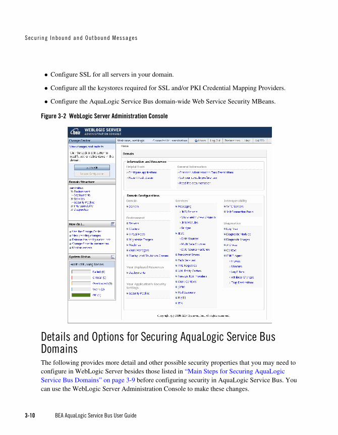
Secur ing Inbound and Outbound Messages
3-10 BEA AquaLogic Service Bus User Guide
Configure SSL for all servers in your domain.
Configure all the keystores required for SSL and/or PKI Credential Mapping Providers.
Configure the AquaLogic Service Bus domain-wide Web Service Security MBeans.
Figure 3-2 WebLogic Server Administration Console
Details and Options for Securing AquaLogic Service Bus DomainsThe following provides more detail and other possible security properties that you may need to configure in WebLogic Server besides those listed in “Main Steps for Securing AquaLogic Service Bus Domains” on page 3-9 before configuring security in AquaLogic Service Bus. You can use the WebLogic Server Administration Console to make these changes.

WebLog ic Ser ve r P re requi s i t es
BEA AquaLogic Service Bus User Guide 3-11
PKI Credential Mapper. A PKI (Public Key Infrastructure) Credential Mapper is a security provider that must be configured with a keystore (with the location of the keystore relative to the domain root), keystore password, keystore type (optional), and keystore provider (optional). This keystore can be the same as the server’s identity keystore or a different one. If you define a proxy service provider, you must configure a PKI credential mapper in your security realm. By default the realm configuration does not have a PKI mapper. For more information, see “Configuring a PKI Credential Mapping Provider” in Configuring WebLogic Security Providers in Securing WebLogic Server.
Warning: After adding or deleting a security provider, you must reboot the server for the security changes to take effect.
Keystores. Both SSL and PKI Credential Mapping require the use of keystores for the storage of SSL server key-pairs, trusted CA (Certification Authority) certificates, and proxy service provider key-pair credentials (for SSL client authentication and Web Service Security). Typically the trusted CA certificates and the server’s SSL key-pair are stored in separate keystores, commonly referred to as identity keystore and trust keystore respectively. You can store the PKI credential mappings in the server’s identity keystore or in a separate keystore. Configure each WebLogic Server to have access to its own copy of each keystore. All entries referred to by the PKI credential mapper must exist in all keystores (same entry with the same alias). For information about configuring keystores in WebLogic Server, see “Identity and Trust” in Security Fundamentals in Understanding WebLogic Security.
SSL. If using SSL, you must configure the WebLogic Server with an SSL port, keystores for storing the server’s SSL private key, digital certificates, trusted CA certificates, and the username-password to the server’s SSL private key. In addition, if client certificate authentication is required, you must enable two-way SSL. When configuring two-way SSL, you must choose between two modes: Client Certificate Requested or Client Certificates Requested and Enforced. BEA recommends that you choose Client Certificate Requested and Enforced. For more information, see “Secure Sockets Layer (SSL)” in Security Fundamentals in Understanding WebLogic Security.
Hostname Verification. When deploying AquaLogic Service Bus in a production environment, BEA recommends you enable that Host Name Verification is enabled. For information about how to do this, see “Using Host Name Verification” in Configuring SSL in Securing WebLogic Server.
Password Digest. If the password digest is used with WS-Security username-password tokens, you must enable the password-digest for the appropriate authentication providers. This instructs the provider to store the password in encrypted form, instead of storing a hash of the password. For more information, see Use a Password Digest in SOAP Messages in the WebLogic Server Administration Console Online Help.

Secur ing Inbound and Outbound Messages
3-12 BEA AquaLogic Service Bus User Guide
Digest Authentication. If password digest authentication is required with WS-Security username password tokens, the wsse:PasswordDigest must be one of the active token types of the appropriate identity assertion provider(s). For more information, see “WebLogic Identity Assertion Provider” under WebLogic Security Service Architecture in Understanding WebLogic Security.
X.509 tokens. If X.509 tokens are used for authentication, X.509 must be one of the active token types for the appropriate identity assertion providers. In addition, you must configure a user-name mapper. X.509 tokens are required when configuring HTTPS proxies with CLIENT-CERT authentication (two-way SSL) and for Web Service Security X.509 token authentication. For more information, see “Identity Assertion and Tokens” under “Authentication” in Security Fundamentals in Understanding WebLogic Security.
Digital Signature. If there is a requirement to check digital signature certificates against the certificate registry, you will have to configure a Certificate Lookup and Validation (CLV) provider with certificate registry enabled. For more information, see “Certificate Lookup and Validation” under “Identity and Trust” in Security Fundamentals in Understanding WebLogic Security.
Note: BEA strongly recommends to use certificate registry whenever using WS-Security digital signatures. You must load your trusted signature verification certificates into the certificate registry. For more information, see “Configuring the Credential Lookup and Validation Framework” in Configuring WebLogic Security Providers in Securing WebLogic Server. and Certificate Registry: Management in WebLogic Server Administration Console Online Help.
Auditing. If auditing is required, you must configure an auditor provider. For more information, see “Configuring a WebLogic Auditing Provider” in Configuring WebLogic Security Providers in Securing WebLogic Server.
Note: AquaLogic Service Bus supports auditing of Web Services Security (WS-Security) errors, but does not support auditing of administrative security actions. To enable WS-Security auditing, start the server with the following system property:
-Dcom.bea.wli.sb.security.AuditWebServiceSecurityErrors=true
Domain-Wide Web Service Security Configuration. WS-Security is configured through WebserviceSecurityMBeans. Two instances of this MBean are automatically configured when you create an AquaLogic Service Bus domain using the BEA WebLogic Configuration Wizard.
– __SERVICE_BUS_INBOUND_WEB_SERVICE_SECURITY_MBEAN__
– __SERVICE_BUS_OUTBOUND_WEB_SERVICE_SECURITY_MBEAN__

Transpo r t -Leve l Secu r i t y
BEA AquaLogic Service Bus User Guide 3-13
You can customize the configuration of these MBeans. For example, you can enable X.509-based WS-Security authentication (X.509 Token profile), for either inbound or outbound messages. As another example, you can enable the use of password digests with username and password tokens, as described in Web Services Security Username Token Profile 1.0, which is available at the following URL:
http://docs.oasis-open.org/wss/2004/01/oasis-200401-wss-username-token-
profile-1.0.pdf
For more information, see Use X.509 certificates to establish identity and Use a password digest in SOAP messages in the WebLogic Server Administration Console Online Help.
Transport-Level SecurityTransport-level security ensures that the connection is secure. You can configure transport security between client applications and AquaLogic Service Bus proxy services and between AquaLogic Service Bus and business services.
The following types of transport security are supported:
HTTPS Transport-Level Security
HTTP Transport-Level Security
Security for JMS, Email, FTP, and File Transport
Transport-Level Security in Message Flow and Service Callout Actions
HTTPS Transport-Level SecurityAquaLogic Service Bus supports HTTPS proxy services and HTTPS business services. HTTPS proxy services receive client requests over the HTTPS protocol. The response to the client is sent over the same HTTPS connection. Throughout this document this is referred to as inbound HTTPS.
Proxy services route messages to HTTPS business services over the HTTPS protocol. In this case, the proxy service is acting as an HTTPS client, opening an HTTPS connection to the business service. The response from the business service is received over the same HTTPS connection. Throughout this document, this is referred to as outbound HTTPS.
Note: AquaLogic Service Bus supports only one SSL network channel. This is called the default WebLogic Server (SSL) secure network channel.
The inbound and outbound scenarios are described in the following sections:

Secur ing Inbound and Outbound Messages
3-14 BEA AquaLogic Service Bus User Guide
Inbound HTTPS Transport-Level Security
Outbound HTTPS Transport-Level Security

Transpo r t -Leve l Secu r i t y
BEA AquaLogic Service Bus User Guide 3-15
Inbound HTTPS Transport-Level SecurityInbound transport-level security applies to the connection between client applications and AquaLogic Service Bus proxy services.
You configure transport-level security for the proxy endpoints using the AquaLogic Service Bus Console while configuring proxy services. For information on how to do this, see Proxy Services in the Using the AquaLogic Service Bus Console.
The AquaLogic Service Bus Console allows you to configure HTTPS proxy endpoints for the following security levels:
None—one-way SSL
Basic—one-way SSL and user-password client authentication
Client Certificate—two-way SSL, both client and server authenticate during the SSL handshake
None—Inbound HTTPSWhen you specify HTTPS without BASIC or CLIENT CERT authentication, you secure your messages with one-way SSL. In one-way SSL, the client initiates the connection and WebLogic Server sends its certificate to the client. In other words, the client authenticates WebLogic Server. For information about configuring SSL certificates in WebLogic Server, see “WebLogic Server Prerequisites” on page 3-9.
Basic—Inbound HTTPSWhen you specify HTTPS with BASIC authentication, authentication takes place over an encrypted channel so passwords are secure. After the one-way SSL connection is established, the client authenticates to WebLogic Server with a username and password. Trust is established by validating the username and password using the authentication providers configured in the WebLogic Server security realm. The client must send its username and password on the HTTP request header.
Warning: When creating an HTTPS proxy service endpoint, the initial transport access-control policy grants access to all requests. To enforce BASIC authentication, you must define a transport-authorization policy for the endpoint.
As mentioned in the warning, if a transport-authorization policy (security policy) for the inbound endpoint is not associated with the endpoint URL, authentication will not occur—the server will accept HTTPS requests without the username and password header and will not challenge the

Secur ing Inbound and Outbound Messages
3-16 BEA AquaLogic Service Bus User Guide
client to provide the username and password. Moreover, authentication will not take place if the client has preemptively included the BASIC username and password header in the request—the server will accept requests with invalid usernames or invalid passwords. After you configure a transport-authorization policy on the proxy service endpoint, the client will be forced to properly authenticate and the server will enforce this access-control policy. For information about security policies, see “Configuring Proxy Service Access Control” on page 3-58.
Client Certificates—Inbound HTTPSClient Certificate authentication provides the highest level of transport security. In addition to the client authenticating WebLogic Server, WebLogic Server will authenticate the client application during the SSL handshake. This is sometimes called two-way SSL. For more information about SSL, see “Secure Sockets Layer (SSL)” in Security Fundamentals in Understanding WebLogic Security.
Although a full description of CLIENT CERT authentication for inbound HTTPS is out of scope in this document, the essentials are as follows: The SSL engine validates the client certificate, which includes making sure that the client holds the private key (via the SSL protocol), establishing a chain of trust from the client certificate to one of the trusted CAs (Certificate Authority) in the trust keystore, checking the certificate expiration, and so on. Additional validation can be performed by configuring WebLogic Server SSL to invoke the Certificate Lookup and Validation Framework during the SSL handshake. After trust in the certificate has been established, the certificate is passed to the identity assertion providers to extract the client identity.
Identity assertion providers are another component of the WebLogic Security Framework. Identity asserters can be configured to extract a field in the certificate to use as the client identity, typically the CN (common name) or E (email) of the SubjectDistinguishedName in the certificate. After extracting the field from the certificate, the extracted client identity is compared to the registered users in the authentication provider. If the client identity matches, the authentication provider collects all groups to which the user belongs. The end result is a signed Java Authentication and Authorization Service (JAAS) Subject with one principal that holds the client identity and one principal for each group to which the user belongs.
Note: If you have configured your server for two-way SSL with Client Certificate Requested But Not Enforced and you have not assigned a transport-level access control policy to the proxy service, the proxy service will accept requests over HTTPS without any client certificates. You must assign a transport-level access control policy to the proxy service.

Transpo r t -Leve l Secu r i t y
BEA AquaLogic Service Bus User Guide 3-17
For more information about identity assertion providers, see Security Fundamentals in Understanding WebLogic Security.

Secur ing Inbound and Outbound Messages
3-18 BEA AquaLogic Service Bus User Guide
Outbound HTTPS Transport-Level SecurityOutbound transport security applies to the connections between AquaLogic Service Bus proxy services and business services.
You configure transport-level security for the outbound endpoints while creating or editing a business service on the Transport Configuration page. For information on how to do this, see Business Services in the Using the AquaLogic Service Bus Console.
The AquaLogic Service Bus Console allows you to configure HTTPS outbound endpoints for the following security levels:
None—one-way SSL
Basic—one-way SSL and user-password client authentication
Client Certificate—two-way SSL, both client and server authenticate during the SSL handshake
In None, Basic, and Client Certificate, the remote server certificate is validated during the SSL handshake. Hostname verification, if enabled, checks the SubjectDistinguishedName in the server certificate against the business service URL. For more information, see “Hostname Verification” under “Secure Sockets Layer (SSL)” in Security Fundamentals in Understanding WebLogic Security.
Note: Hostname verification should be enabled in a production environment.
None—Outbound HTTPSWhen you specify HTTPS without BASIC or CLIENT CERT authentication, you secure your messages with one-way SSL. In one-way SSL, the proxy service initiates the connection, but does not authenticate itself to the business service.
Basic—Outbound HTTPSWhen you specify HTTPS with BASIC authentication, authentication takes place over an encrypted channel so that passwords are secure. After the one-way SSL connection is established, the proxy service authenticates itself to the business service with a username and password. The proxy service uses the username and password associated with the service account that is defined for the business service. You specify the service account on the business service HTTPS Transport Configuration page and associate the username and password with the service account in the Credentials section of the Security Configuration module. For more information on credentials and service accounts, see “Credentials” on page 3-55.

Transpo r t -Leve l Secu r i t y
BEA AquaLogic Service Bus User Guide 3-19
Client Certificate—Outbound HTTPSClient Certificate authentication provides the highest level of transport security. In this case, two-way SSL is established. During the SSL handshake, the proxy service authenticates itself to the business service with an SSL certificate. The SSL private-key and corresponding certificate that the proxy service uses to authenticate to the business service is supplied by the proxy service provider defined for that proxy service. This means that before specifying CLIENT CERT authentication, you must configure a proxy service provider and associate an SSL client key-pair with that proxy service provider. For more information, see “Proxy Service Providers” on page 3-56.
HTTP Transport-Level SecurityThe AquaLogic Service Bus Console allows you to configure AquaLogic Service Bus to require BASIC authentication for inbound and outbound endpoints. In inbound BASIC authentication, the client authenticates to WebLogic Server with a username and password. In outbound BASIC authentication, the proxy service authenticates itself to the business service using a username and password. Unlike HTTPS transport-level security, when using HTTP the business service does not authenticate itself to the proxy service.
Warning: Although, the AquaLogic Service Bus Console allows you to specify BASIC authentication for HTTP connections, this is strongly discouraged because the password is sent in clear text. However, it is safe to send passwords over HTTPS, as HTTPS provides an encrypted channel.
If you do use BASIC Authentication for HTTP outbound endpoints, you must specify a Service Account. This service account maps the username and password that AquaLogic Service Bus uses to connect to the business service. For more information, see “Service Accounts” on page 3-55.
Also if you use BASIC Authentication for HTTP inbound endpoints, you must associate a transport-authorization policy with the proxy service URI. For more information, see “Basic—Inbound HTTPS” on page 3-15.

Secur ing Inbound and Outbound Messages
3-20 BEA AquaLogic Service Bus User Guide
Security for JMS, Email, FTP, and File TransportThis section provides information about protecting JMS, email, FTP, and file transport:
JMS Transport-Level Security
Email and FTP Transport-Level Security
File Transport Security
JMS Transport-Level SecurityYou can configure AquaLogic Service Bus to provide transport security over JMS for inbound messages to a proxy service and outbound messages from a proxy service. The connection to JMS servers can be secured using the T3S protocol (T3 over SSL). While this does not provide end-to-end security for JMS messaging, it does provide the following:
The option to use a secure SSL channel for communication between AquaLogic Service Bus and the JMS server for sending or receiving JMS messages.
The ability to specify the credentials (username and password) that AquaLogic Service Bus proxy services use to authenticate while establishing the connection to a JMS server and/or while looking up JMS destinations in the JNDI tree.
For a description of the T3 protocol, see Using WebLogic RMI with T3 Protocol in Programming WebLogic RMI.
Inbound JMS Transport-Level SecurityAs previously mentioned, for inbound transport, you can designate that the connection to the JMS server uses the T3S protocol. This is done while creating or editing a proxy service by selecting the Use SSL check box on the Transport Configuration page. For information on how to do this, see Proxy Services in the Using the AquaLogic Service Bus Console.
If the JMS administrator has restricted access to a JMS connection pool, you need to configure your proxy service to authenticate when connecting to the JMS server, as follows:
1. To supply the username and password to the JMS server, create a (JMS) service account in the Project Explorer module in the AquaLogic Service Bus Console.
2. While creating or editing a proxy service, designate the JMS service account on the JMS Transport Configuration page.

Transpo r t -Leve l Secu r i t y
BEA AquaLogic Service Bus User Guide 3-21
3. Specify the username and password for the JMS service account using the Credentials section of the Security Configuration module. If the JMS server is in a remote WebLogic Server domain, trust must be established between the domains.
For information on how to configure service accounts, see Service Accounts in the Using the AquaLogic Service Bus Console.
Outbound JMS Transport-Level SecurityFor outbound messages, you can designate that the connection to the JMS server uses the T3S protocol. This is done while creating or editing a business service by selecting the Use SSL check box on the Transport Configuration page. For specific information on how to do this, see Business Services in the Using the AquaLogic Service Bus Console.
AquaLogic Service Bus supports access control for both the JMS connection pool and the JNDI entry for the JMS destination (queue or topic). You can configure the access-control policies for these two resources independently. When access control to the JMS connection pool has been configured, AquaLogic Service Bus must authenticate while establishing the connection to the JMS server. When access control to the JNDI entry has been configured, AquaLogic Service Bus must authenticate during the JNDI lookup. You must specify which service account to use for authentication when accessing either resource.
AquaLogic Service Bus can communicate with the local JMS server or a foreign JMS server.
For information on configuring access control to a WebLogic JMS Server and the JNDI entry, see Configuring JMS System Resources in Configuring and Managing WebLogic JMS and Securing WebLogic Resources.
To configure AquaLogic Service Bus to authenticate while establishing the connection to the JMS server, take the following steps:
1. To supply the username and password to the JMS server, create a service account for the JMS server in the Project Explorer module of the AquaLogic Service Bus Console.
2. Specify the username and password for the JMS service accounts using the Credentials section of the Security Configuration module.
3. While creating or editing the business service, designate this service account as the JMS service account on the JMS Transport Configuration page, as shown in Figure 3-3.

Secur ing Inbound and Outbound Messages
3-22 BEA AquaLogic Service Bus User Guide
To configure AquaLogic Service Bus to authenticate while looking up the JNDI entry for the JMS queue or topic, take the following steps:
1. To supply the username and password for the JNDI entry, create a service account for the JNDI entry in the Project Explorer module of the AquaLogic Service Bus Console.
2. Specify the username and password for the JNDI service accounts using the Credentials section of the Security Configuration module.
3. While creating or editing the business service, designate this service account as the JNDI service account on the JMS Transport Configuration page, as shown in the following figure.
Figure 3-3 JMS Transport Configuration Page
For specific information on how to configure service accounts, see Service Accounts in the Using the AquaLogic Service Bus Console.
Warning: When you employ a service account for authentication on outbound JMS transports, it can take up to 60 seconds for any changes you make to that service account (or to the policy) to take effect on the server.

Transpo r t -Leve l Secu r i t y
BEA AquaLogic Service Bus User Guide 3-23
By default, WebLogic Server JMS checks the ACL for each destination every 60 seconds. You can change this default time or ensure security checks are performed on JMS resources for every send, receive, and getEnumeration action on a JMS resource. To do so, set the weblogic.jms.securityCheckInterval attribute. A value of zero for this attribute ensures that an authorization check is performed for every send, receive, and getEnumeration action on a JMS resource.
For complete information about securing your applications, see Ensuring the Security of Your Production Environment in Securing a Production Environment.
Email and FTP Transport-Level SecurityThe supported security method for email or FTP transport is the username and password needed to connect to the email or FTP server.
To secure email, you must designate a service account as an alias for the username and password in the AquaLogic Service Bus Console. The service will use the username and password to authenticate to the SMTP server.
To secure FTP, in the AquaLogic Service Bus Console, select external_user and designate a service account as an alias for the username and password. The service will use the username and password to authenticate to the FTP server.
For information about how to add security to email and FTP transport, see “Adding a Business Service” in Business Services in the Using the AquaLogic Service Bus Console.
File Transport SecurityThe supported security method for file transport is the user login to the computer on which the files are located.
Transport-Level Security in Message Flow and Service Callout ActionsTransport-level security is available from within the proxy service pipeline from the following:
Message Flow—in a proxy service, the processing of messages is driven by metadata specified in the message flow definition. This definition can use the client identity to apply a transformation to a message or determine which pipeline branch the message flow should follow. If you need to specify authenticated transport-level user information in the message flow, you can do this using the security element in the inbound context variables. For information on how to use the security element, see “Inbound and Outbound Variables”

Secur ing Inbound and Outbound Messages
3-24 BEA AquaLogic Service Bus User Guide
in Message Context, and for information on configuring message flow, see “Message Flow” in Proxy Services in the Using the AquaLogic Service Bus Console.
Service Callout—in a message flow, you use a Service Callout to look up information in a registered business service. You can apply transport-level security to the connection using HTTP or HTTPS.
Message-Level Security (Web Services Security)This section includes information on the following topics:
About Web Services Security
Inbound Web Services Security
Outbound Web Services Security
About Web Services SecurityWeb Services Security (WS-Security) is an OASIS standard that defines interoperable mechanisms to incorporate message-level security into SOAP messages. WS-Security supports message integrity and message confidentiality. It also defines an extensible model for including security tokens in a SOAP envelope and a model for referencing security tokens from within a SOAP envelope. WS-Security token profiles specify how specific token types are used within the core WS-Security specification. Message integrity is achieved through the use of XML digital signatures. Message confidentiality is achieved through the use of XML encryption. WS-Security allows you to specify the parts of the SOAP message that are digitally signed or encrypted. AquaLogic Service Bus supports Web Service Security over HTTP, HTTPS, and one-way JMS. AquaLogic Service Bus supports version 1.0 of WS-Security. For more information on WS-Security, see Web Service Security: SOAP Message Security 1.0 (WS-Security 2004) at the following URL:
http://docs.oasis-open.org/wss/2004/01/oasis-200401-wss-soap-message-security-1.0.pdf
AquaLogic Service Bus supports the following WS-Security token profiles:
Web Services Security: Username Token Profile 1.0, at http://docs.oasis-open.org/wss/2004/01/oasis-200401-wss-username-token-profile-1.0.pdf

Message-Leve l Secu r i t y (Web Serv i ces Secur i t y )
BEA AquaLogic Service Bus User Guide 3-25
Web Services Security X.509 Token Profile 1.0, at http://docs.oasis-open.org/wss/2004/01/oasis-200401-wss-x509-token-profile-1.0.pdf
Web Services Security SAML Token Profile 1.0, at http://docs.oasis-open.org/wss/oasis-wss-saml-token-profile-1.0.pdf
Message-level security provides a level of flexibility not present in transport-level security. It can ensure that SOAP messages are secure even when the transmission involves one or more intermediaries and because the security measures are built into the message, the message can be protected point-to-point or end-to-end. The ability to specify which parts of the message are signed or encrypted is useful for routing messages in AquaLogic Service Bus. Message-level security provides confidentiality and integrity of the protected information where needed and along the entire message path.
Message-level security is configured using security policy statements, as specified by the Web Service Policy (WS-Policy). WS-Policy statements are bound to a business or proxy service. The mechanism that binds policies to services is called WS-PolicyAttachment. This mechanism describes how to bind the policies by adding policy references to WSDL documents. These policy references may point to policies included in the WSDL document or may be URL references to external policies. A WSDL may import other WSDLs containing policy attachments, either inlined or external. For more information about WS-Policy, see “Web Service Policy” on page 3-33.
When Web services security (WS-Security) is applied to a message, a new SOAP header is added to the message envelope. The new header includes the XML-DSIG digital signatures, security tokens, and other constructs. These security tokens can be used for the following:
Sender authentication
Key wrapping—which is carrying a randomly generated symmetric encryption key encrypted with the recipient’s public key
Carrying the signature verification certificate
Including the sender’s encryption public certificate—which provides the means for the recipient to encrypt the response.
When the recipient consumes the secured envelope, the cryptographic operations are performed in reverse order and the security header is removed. The recipient then verifies that the message conforms to its policy. For example, the recipient confirms that the required message parts were signed and/or encrypted and that the required tokens are present with the required claims.

Secur ing Inbound and Outbound Messages
3-26 BEA AquaLogic Service Bus User Guide
Inbound Web Services SecurityThis section includes information on the following topics:
About Inbound Web Services Security
Client Request and Proxy Service Response
How to Configure a WS-Security Pass-Through Scenario
How to Configure an Active Intermediary WS-Security Proxy Service
About Inbound Web Services SecurityInbound WS-Security applies to messages between client applications and AquaLogic Service Bus proxy services. It applies to both the request and the response between the client application and AquaLogic Service Bus.
As previously mentioned, you specify the details for inbound message-level security using WS-Policy statements, which are inlined within or referenced through WSDLs. AquaLogic Service Bus provides two types of inbound message security: active intermediary and pass-through.
Note: For SOAP-JMS, WS-Security is supported only for one-way messages. It is not supported for request/response messaging.
Client Request and Proxy Service ResponseWhen a client makes a request to a proxy service and the proxy service responds to the request, two security scenarios are available:
Active-Intermediary—in this scenario, the client applies WS-Security to the request and response messages. The proxy service processes the message header and enforces the security policy on the messages. For example, the client encrypts and signs the message and sends it to the proxy service, the proxy service decrypts the message and verifies the digital signature, then routes the message. Before the proxy service sends the response back to the client, the proxy service signs and encrypts the message. The client then decrypts the message and verifies the proxy service’s digital signature.
Pass-Through—in this scenario, the client applies WS-Security to the request and response messages. The proxy service does not process the security header; instead it passes the secured request message untouched to a business service. Although AquaLogic Service Bus does not apply any WS-Security to the message, it can route the message based on values in the header. After the business service receives the message, it processes

Message-Leve l Secu r i t y (Web Serv i ces Secur i t y )
BEA AquaLogic Service Bus User Guide 3-27
the security header and acts on the request. Note that the business service must be configured with WS-Policy security statements. The secured response message is passed untouched to the client. For example, the client encrypts and signs the message and sends it to the proxy service. The proxy service does not decrypt the message or verify the digital signature; it simply routes the message to the business service. The business service decrypts the messages and verifies the digital signature, and then processes the request. The response path is similar.
Note: In both scenarios, the proxy service has to be configured with WS-Policy statements. These WS-Policy statements are available to clients (from the dynamic WSDL).
Warning: Encrypted inbound response messages: If the response policy of the proxy service specifies encryption, the client must send its certificate to the proxy service on the request. The proxy service will encrypt its response using the client’s public key. The client certificate must not be the same as the proxy service’s encryption certificate. The client cannot be configured to use the same encryption credentials as the proxy service.
How to Configure a WS-Security Pass-Through ScenarioThis following steps outline the basic steps for configuring a pass-through WS-Security scenario. Some steps are optional.
1. Import the WSDL for the WS-Security-enabled business service into the AquaLogic Service Bus WSDL repository. This WSDL must have the Web service security policies attached to it. The policies may be inlined within the WSDL or the WSDL may have references to external policies.
2. If the WSDL has external policy references, you must import these policies into the AquaLogic Service Bus WS-Policy repository and resolve the WSDL dependencies. For more information see “Resolving Unresolved WSDL References” in WSDLs in Using the AquaLogic Service Bus Console.
3. If any operation request policy requires encryption, you must make sure the encryption certificate is embedded in the policy. Otherwise you will get an error message while creating the business service from this WSDL.
4. When you create a business service, if any operation request policy includes an Identity assertion with Username Token as one of the supported token types, you must define a service account; map a username and password to this service account; and in the Service Account field, specify this service account for the Web Service Security Username Token. For information on how to perform these actions, see Service Accounts and Business Services in the Using the AquaLogic Service Bus Console.

Secur ing Inbound and Outbound Messages
3-28 BEA AquaLogic Service Bus User Guide
5. Create a business service from the WSDL you imported in step 4. For information on how to do this, see Business Services in the Using the AquaLogic Service Bus Console.
6. Create a proxy service that routes to the business service created in the previous step. Typically this proxy service is created from the same WSDL as the business service. In the Web Services Security Configuration page, make sure that the Process WS-Security Header check box is not selected. For more information, see Proxy Services in Using the AquaLogic Service Bus Console.
7. If routing is based on the operation being invoked when the request SOAP body is encrypted, you must specify a proxy service operation selection algorithm other than the SOAP body algorithm. Make sure the actions in the proxy service pipeline do not modify the WS-Security header or any parts of the SOAP envelope that are signed or encrypted. Changes to clear-text message parts covered by digital signatures almost always break the digital signature because the signature cannot be verified later.
How to Configure an Active Intermediary WS-Security Proxy ServiceThe following steps outline the basic steps for configuring a pass-through Web Service Security scenario. Some steps are optional.
1. Import the WSDL for the WS-Security-enabled proxy service into the AquaLogic Service Bus WSDL repository. This WSDL must have the WS-Security policies attached to it. The policies may be inlined within the WSDL or the WSDL may have references to external policies.
2. If the WSDL has external policy references, you must import these policies into the AquaLogic Service Bus WS-Policy repository and resolve the WSDL dependencies. For more information see “Resolving Unresolved WSDL References” in WSDLs in the Using the AquaLogic Service Bus Console.
3. If any operation request policy requires encryption, you must make sure that the Confidentiality assertion is an abstract assertion (in other words, the certificate must not be embedded in the policy). Otherwise, you will get error messages while creating the proxy service from this WSDL. You must configure a proxy service provider and you must assign an encryption credential to the proxy service provider. For information on how to do this, see “Adding a Credential” in Security Configuration in the Using the AquaLogic Service Bus Console.
4. If any operation response policy requires digital signatures, you must configure a proxy service provider and you must assign a digital signature credential to the proxy service provider. For information on how to do this, see “Adding a Credential” in Security Configuration in the Using the AquaLogic Service Bus Console.

Message-Leve l Secu r i t y (Web Serv i ces Secur i t y )
BEA AquaLogic Service Bus User Guide 3-29
5. If any operation request policy requires digital signatures, you must register the accepted client signature verification certificates in the WebLogic Server Certificate Registry. The certificate registry in part of the WebLogic Certificate Lookup and Validation Framework. (See “What is the Certificate Lookup And Validation Framework?” on page 3-5.) The certificate in the message signature will be verified against the certificate registry. For information on how to do this, see “Configuring the Certificate Lookup and Validation Framework” in Configuring WebLogic Security Providers in Securing WebLogic Server.
6. If any operation request policy requires authentication with a WS-Security Username/Password token with password digest, make sure to enable password digests. For more information, see “Domain-Wide Web Service Security Configuration,” “Password Digests,” and “Digest Authentication” in “WebLogic Server Prerequisites” on page 3-9.
7. If any operation request policy requires authentication with a WS-Security X.509 certificate token, make sure to enable the UseX509ForIdentity property of the WebserviceSecurityMBean named __SERVICE_BUS_INBOUND_WEB_SERVICE_SECURITY_MBEAN__ in the WebLogic Server Administration Console. For more information, see “Domain-Wide Web Service Security Configuration,” in the “WebLogic Server Prerequisites” on page 3-9.
8. Create a proxy service from the WSDL imported in step 1. If you configured a proxy service provider, specify that service provider in the General Configuration page of the AquaLogic Service Bus Console. Select the Process WS-Security Header check box in the Web Services Security Configuration page. For more information, see Proxy Services in Using the AquaLogic Service Bus Console.
9. If any operation request policy specifies the use of SAML tokens, you must configure a SAML asserting party for this proxy service. For more information, see “Inbound Authentication with a SAML WS-Security Token” on page 3-43.
Outbound Web Services SecurityThis section contains information on the following topics:
About Outbound Web Services Security
How to Configure Outbound Web Services Security
Disabling Outbound WS-Security in the Pipeline

Secur ing Inbound and Outbound Messages
3-30 BEA AquaLogic Service Bus User Guide
About Outbound Web Services SecurityOutbound WS-Security refers to security between AquaLogic Service Bus proxy services and business services. It includes both the request and response between business applications and proxy services. Outbound WS-Security applies only to SOAP-HTTP or SOAP-JMS business services. You specify the details for outbound message-level security using WS-Policy statements attached (inlined or referenced) from the WSDL of the business service.
Note: For SOAP-JMS, WS-Security is supported only for one-way messages. It is not supported for request/response messaging.
Warning: Encrypted back-end response messages: If the response policy of the business service specifies encryption, the proxy service will send its encryption certificate to the business service on the request. The business service will encrypt its response using the proxy service’s public key. The proxy service encryption credential must not be the same as the business service encryption credential.
How to Configure Outbound Web Services SecurityThis section outlines the basic steps to configure an outbound Web Service Security scenario. Some steps are optional.
1. Import a WSDL with WS-Policy statements attached (inlined or referenced) from the business service. If the security policies are referenced, they must be resolved. For information about resolving WSDL references, see “Resolving Unresolved WSDL References” in WSDLs in the Using the AquaLogic Service Bus Console.
2. Define the business service in AquaLogic Service Bus using the WSDL as a template. If the WS-Policy of the business service requires UsernameToken authentication, you must specify a service account and assign a username and password to the service account. Proxy services that route to this business service will get the username and password for WS-Security Username Token authentication from the service account.
3. If the business service request operation policy specifies a digital signature, you must configure a proxy service provider and assign a digital signature credential to the proxy service provider.
4. If the business service response operation policy specifies encryption (that is, the business service encrypts the response with the proxy’s encryption public key), you must configure a proxy service provider and assign an encryption credential to the proxy service provider.
5. If the business service request operation policy specifies an Identity assertion and X.509 token is one of the supported tokens, you may have to configure a proxy service provider and assign

Message-Leve l Secu r i t y (Web Serv i ces Secur i t y )
BEA AquaLogic Service Bus User Guide 3-31
a WS-Security X.509 Token credential to that proxy service provider. Whether this is required or optional depends on the identity policy. If X.509 token is the only supported token type, the X.509 credential is required. If the policy accepts other token types besides X.509 tokens, at least one of the requirements must be met by the proxy configuration.
6. If any operation request policy requires authentication with a WS-Security Username/Password token with password digest, make sure to enable password digests. For more information, see “Domain-Wide Web Service Security Configuration,” “Password Digests,” and “Digest Authentication” in “WebLogic Server Prerequisites” on page 3-9.
7. In the proxy service, configure the route node and operations on the business service.
8. If the WS-Policy specifies using SAML assertions, you must also configure a WebLogic SAML Credential Mapping Provider V2 asserting party. For more information, see “SAML Credential Mapping” on page 3-42.
Note: When the WS-Policy of a business service requires messages to be encrypted, you must make sure that the policy of the business service with the encryption certificate embedded is inlined in the WSDL. Additionally, you must refer to this WSDL when defining the business service in the AquaLogic Service Bus Console. If the business service is a WebLogic Server 9.0 or 9.1 Web service or an AquaLogic Service Bus proxy service, you can get its WSDL by pointing a browser to <service-url>?WSDL. WebLogic Server will automatically inline the Web service policies in the WSDL and, if any policy specifies an encrypted request, the encryption certificate will be automatically embedded in the WSDL. Listing 3-1 shows an example WSDL with an inlined policy inlined and an embedded encryption certificate. Pay special attention the KeyInfo element inside the policy and the SecurityTokenReference. The value of the BinarySecurityToken element is the base-64 encoded encryption certificate (the value is truncated in the sample). If your certificate is in PEM format, the content of the PEM file (without the PEM prefix and suffix) is the base-64 encoded representation of the certificate. If your encryption certificate is stored in a JDK keystore, you can easily export it to a PEM file.
Listing 3-1 Example of WSDL with Policy Inlined and Embedded Encryption Certificate
<definitions name="WssServiceDefinitions"targetNamespace="http://com.bea.alsb/tests/wss"xmlns="http://schemas.xmlsoap.org/wsdl/"xmlns:wsu="http://docs.oasis-open.org/wss/2004/01/oasis-200401-wss-wssecurit
y-utility-1.0.xsd"xmlns:wsp="http://schemas.xmlsoap.org/ws/2004/09/policy"...>

Secur ing Inbound and Outbound Messages
3-32 BEA AquaLogic Service Bus User Guide
<wsp:UsingPolicy xmlns:n1="http://schemas.xmlsoap.org/wsdl/" n1:Required="true"/>
<wsp:Policy wsu:Id="Encrypt.xml"><wssp:Confidentiality
xmlns:wssp="http://www.bea.com/wls90/security/policy"><wssp:KeyWrappingAlgorithm
URI="http://www.w3.org/2001/04/xmlenc#rsa-1_5"/><wssp:Target><wssp:EncryptionAlgorithm
URI="http://www.w3.org/2001/04/xmlenc#tripledes-cbc"/><wssp:MessageParts
Dialect="http://schemas.xmlsoap.org/2002/12/wsse#part">wsp:Body()</wssp:MessageParts>
</wssp:Target><wssp:KeyInfo><wssp:SecurityToken
TokenType="http://docs.oasis-open.org/wss/2004/01/oasis-200401-wss-x509-token-profile-1.0#X509v3"/>
<wssp:SecurityTokenReference><wssp:Embedded><wsse:BinarySecurityToken
EncodingType="http://docs.oasis-open.org/wss/2004/01/oasis-200401-wss-soap-message-security-1.0#Base64Binary"
ValueType="http://docs.oasis-open.org/wss/2004/01/oasis-200401-wss-x509-token-profile-1.0#X509v3"
xmlns:wsse="http://docs.oasis-open.org/wss/2004/01/oasis-200401-wss-wssecurity-secext-1.0.xsd">MIICfjCCAeegAwIBAgIQV/PDyj3...
</wsse:BinarySecurityToken></wssp:Embedded>
</wssp:SecurityTokenReference></wssp:KeyInfo>
</wssp:Confidentiality></wsp:Policy>
<binding name="WssServiceSoapBinding" type="tns:WssService"><soap:binding style="document"
transport="http://schemas.xmlsoap.org/soap/http"/><operation name="getPurchaseOrder"><soap:operation soapAction="" style="document"/><input><soap:body parts="parameters" use="literal"/><wsp:Policy>
<wsp:PolicyReference URI="#Encrypt.xml"/></wsp:Policy>
</input><output>

Web Se rv ice Po l i cy
BEA AquaLogic Service Bus User Guide 3-33
<soap:body parts="parameters" use="literal"/></output>
</operation></binding>
...
</definitions>
Disabling Outbound WS-Security in the PipelineThe doOutBoundWSS property of the security element in the message context controls outbound WS-Security. If doOutboundWss is true, the proxy service applies WS-Security, that is, it signs and/or encrypts and/or add security tokens, to the outbound message according to the WS-Policy for the target service. If doOutboundWss is false, the proxy service does not apply WS-Security to the outbound message.
In a WS-Security pass-through scenario, the proxy service receives a request that already has WS-Security applied by the client, but the proxy does not process the WS-Security payload. The proxy service simply routes this request to the back-end service. This is also called a passive intermediary scenario. When the proxy service is a passive intermediary, an incoming secured message remains signed/encrypted in the AquaLogic Service Bus message flow and must therefore not be re-signed or re-encrypted on outbound dispatch.
During routing or publishing, the route node automatically initializes this property when a routing destination is set. The default value for doOutboundWss depends on the WS-Security configuration of both proxy and target services as follows:
If the target service does not have a WS-Security policy, doOutboundWss is set to false.
If the proxy service has a WS-Policy and the Process WS-Security Header flag is false, that is, the proxy service is a passive intermediary, doOutboundWss is set to false,
Otherwise, doOutboundWss is set to true.
You can modify the value of the doOutboundWss element in a routing (or publish) outbound request action.
Web Service PolicyThis section contains information on the following topics:

Secur ing Inbound and Outbound Messages
3-34 BEA AquaLogic Service Bus User Guide
About Web Service Policy
Web Services Policy Attachment
Effective Policy
Out-of-the-Box WS-Policy Statements
About Web Service PolicyWeb Services Policy (WS-Policy) is an extensible XML-based framework that extends the configuration of a Web service with domain specific assertions and specifies the requirements, expectations, and capabilities of Web services. In AquaLogic Service Bus, WS-Policy is used for configuration of message-level security in business and proxy services using security policy statements. For more information, see Configuring Security in Programming Web Services for WebLogic Server.
Note: The policy assertions used in WS-Policy to configure message-level security in AquaLogic Service Bus are based on the assertions described in the December 18, 2002 version of the Web Services Security Policy Language (WS-SecurityPolicy) specification. This means that although the exact syntax and usage of the assertions in AquaLogic Service Bus is different from the specification, they are similar in meaning to those described in the specification. Note that the assertions in this release of AquaLogic Service Bus are not based on the latest update of the specification (13 July 2005). The policy assertions used in AquaLogic Service Bus are fully compatible with policy assertions used in WebLogic Server 9.0 and 9.1 Web services.
WS-Policy statements ensure message integrity, confidentiality, and message origin authentication by specifying signing, encryption, application of security algorithms, and authentication mechanisms. A WS-Policy statement may include both security and reliable messaging assertions. At this time, AquaLogic Service Bus supports only security assertions, not reliable messaging assertions.
WS-Policy statements are XML documents, which may be inlined or referenced from WSDLs. A WSDL may import other WSDLs containing policy attachments, either inlined or referenced. You can associate one or more WS-Policy statements to different WSDL constructs as described later in this chapter.
In AquaLogic Service Bus, WS-Policies are required to have a wsu:Id attribute from the following namespace:
http://docs.oasis-open.org/wss/2004/01/oasis-200401-wss-wssecurity-utility-1.0.xsd

Web Se rv ice Po l i cy
BEA AquaLogic Service Bus User Guide 3-35
The value of this attribute must be unique across all WS-Policy statements in the AquaLogic Service Bus repository. Note that this attribute is optional in the WS-Policy schema.
Listing 3-2 shows a WS-Policy with a security policy assertion that specifies encryption of the SOAP body.
Listing 3-2 Sample WS-Policy
<wsp:Policyxmlns:wsp="http://schemas.xmlsoap.org/ws/2004/09/policy"xmlns:wssp="http://www.bea.com/wls90/security/policy"xmlns:wsu="http://docs.oasis-open.org/wss/2004/01/oasis-200401-wss-wssecurity-utility
-1.0.xsd"wsu:Id="encryptWithX509Token">
<wssp:Confidentiality><wssp:KeyWrappingAlgorithm
URI="http://www.w3.org/2001/04/xmlenc#rsa-1_5"/><wssp:Target>
<wssp:EncryptionAlgorithm URI="http://www.w3.org/2001/04/xmlenc#tripledes-cbc"/>
<wssp:MessageParts>wsp:GetBody(.)</wssp:MessageParts></wssp:Target><wssp:KeyInfo>
<wssp:SecurityToken TokenType="http://docs.oasis-open.org/wss/2004/01/oasis-200401-wss-x509-token-profile-1.0#X509v3"/>
</wssp:KeyInfo></wssp:Confidentiality>
</wsp:Policy>
For information on using WS-Policy in the AquaLogic Service Bus Console, see WS-Policies, especially “Resolving Unresolved WSDL References,” in Using the AquaLogic Service Bus Console.
Web Services Policy AttachmentWS-Policy Attachment, defines the mechanisms for assigning policies to Web services. WebLogic Server 9.0, and subsequently, AquaLogic Service Bus, implements WSDL policy attachment. Policies statements may be inlined in a WSDL document by adding a <wsp:Policy>

Secur ing Inbound and Outbound Messages
3-36 BEA AquaLogic Service Bus User Guide
element as a child of the <wsdl:definition> element. An XML fragment identifier is used to reference inlined policies.
Referenced WS-Policy statements are associated with a Web service by adding one or more of the following policy URI attributes or policy reference elements to WSDL elements (which type depends on what the WSDL schema allows):
PolicyURIs—a global attribute whose value is a list of URIs. Each URI is a single policy reference. Use for WSDL elements that allow only attribute extensibility.
PolicyReference—a global element with a URI attribute, which also includes a digest and digest algorithm. The URI is a reference to a policy. Use for WSDL elements that allow only element extensibility.
Using PolicyURIs or PolicyReference, you can reference one or more policies. The references may be local to the WSDL document (fragment URIs) or external.
WS-Policy Attachment also defines a <wsp:UsingPolicy/> element that must appear as a child to the <wsdl:definitions> element whenever a WSDL has policy attachments. To ensure that proxy and business services are capable of processing the policy attachments, this element can be marked as a mandatory extension (wsdl:required="true") in the WSDL.
Warning: If the UsingPolicy tag is missing from the WSDL, AquaLogic Service Bus ignores any WS-Policy present in the WSDL.
Listing 3-3 shows a WSDL with two inlined policies. One inlined policy, policy1, is referenced from the input part of operation doFoo on portType Sample using the policyURIs syntax with a fragment identifier. The other inlined policy, policy2, is referenced from operation doFoo in binding SampleBinding using the nested PolicyReference syntax.
Listing 3-3 WSDL with Policy References to Inline Policy
<definitions...xmlns:wsp="http://schemas.xmlsoap.org/ws/2004/09/policy"
xmlns:wsu="http://docs.oasis-open.org/wss/2004/01/oasis-200401-wss-wssecurity-utility-1.0.xsd">
<wsp:UsingPolicywsdl:Required="true"xmlns:wsdl="http://schemas.xmlsoap.org/wsdl/"/>
<wsp:Policy wsu:Id="policy1">...</wsp:Policy>

Web Se rv ice Po l i cy
BEA AquaLogic Service Bus User Guide 3-37
<wsp:Policy wsu:Id="policy2">...</wsp:Policy>
...
<portType name="Sample"><operation name="doFoo" parameterOrder="data">
<input message="tns:foo" wsp:PolicyURIs="#policy1"/><output message="tns:fooResponse"/>
</operation></portType>
<binding name="SampleBinding" type="tns:Sample"><soap:binding style="document"
transport="http://schemas.xmlsoap.org/soap/http"/><operation name="doFoo">
<wsp:Policy><wsp:PolicyReference URI="#policy2"/>
</wsp:Policy><soap:operation
soapAction="http://com.bea.samples/sample/doFoo" style="document"/>
<input><soap:body namespace="http://com.bea.samples/sample"
use="literal"/></input><output>
<soap:body namespace="http://com.bea.samples/sample" use="literal"/>
</output></operation>
</binding>
...
</definitions>
Effective PolicyYou can associate WS-Policies statements with the different policy subjects. A policy subject is an entity, such as service, endpoint, operation, or message, with which a policy can be associated. A policy scope is the collection of policy subjects to which a policy applies. For example, the policy scope implied by a policy attached to wsd:binding/wsdl:operation/wsdl:input is the input message, the operation, the endpoint, and the service.
The effective policy for a given policy subject is the merge of all policies whose scopes contain that policy subject. In other words, a policy scope is the collection of policy subjects to which a

Secur ing Inbound and Outbound Messages
3-38 BEA AquaLogic Service Bus User Guide
policy applies. For example, the effective policy of the input message of a binding operation is the merge of the following:
all policies attached to the input message of the binding operation
all policies attached to the binding operation
all policies attached to the binding
all policies attached to the input message of the port-type operation
all policies attached to the port-type operation
all policies attached to the port-type
all policies attached to the service
Note: When a proxy service is defined from a binding, any WS-Policy attached to the service or port is ignored.
The AquaLogic Service Bus Console displays the effective policy (read only) when configuring a business or proxy service with WS-Policy statements, as shown in the following figure.
Figure 3-4 Effective Policy
Out-of-the-Box WS-Policy StatementsWebLogic Server includes three out-of-the-box WS-Policy statements. Most of the time a combination of one or more of these policies will address your requirements. However, you can

Web Se rv ice Po l i cy
BEA AquaLogic Service Bus User Guide 3-39
write your own WS-Policies, import them to AquaLogic Service Bus, and refer to them from the WSDL.
To use the out-of-the-box policies, reference them from any WSDL using URIs, such as policyURIs="policy:Auth.xml". The following policies are included with WebLogic Server.
Auth.xml—specifies that the client application invoking the Web service must authenticate itself. The policy does not specify what type of security tokens are accepted. This depends on the server configuration, specifically the WebserviceSecurityMBean instances. For more information, see “WebLogic Server Prerequisites” on page 3-9.
Encrypt.xml—the SOAP body must be encrypted with 3DES-CBC. The key wrapping algorithm is RSA 1.5. A symmetric key for Triple DES (Data Encryption Standard) is generated by the client and encrypted for the recipient with RSA 1.5.
Sign.xml—this policy ensures message integrity. It requires the client to sign the SOAP body. It also requires that the WS-Security engine on the client add a signed timestamp to the wsse:Security header—which prevents certain replay attacks. All system headers are also signed. The digital signature algorithm is RSA-SHA1. Exclusive XML canonicalization is used.
The system headers are:
– wsrm:SequenceAcknowledgement
– wsrm:AckRequested
– wsrm:Sequence
– wsa:Action
– wsa:From
– wsa:To
– wsa:FaultTo
– wsa:MessageID
– wsa:RelatesTo
– wsa:ReplyTo
– wsu:Timestamp
– wsax:SetCookie
The namespace prefixes correspond to the namespaces in the following table:

Secur ing Inbound and Outbound Messages
3-40 BEA AquaLogic Service Bus User Guide
The out-of-the-box policies are located in the BEA_HOME/weblogic90/server/lib/weblogic.jar, where BEA_HOME is the directory in which your BEA products are installed. For more information on these policies, see “Use of WS-Policy Files for Message-Level Security Configuration” in Configuring Security in Programming Web Services for WebLogic Server.
Listing 3-4 shows a WSDL with references to two of the out-of-the-box policies.
Listing 3-4 WSDL with Policy References to Out-Of-The-Box Policies
<definitions
...
xmlns:wsp="http://schemas.xmlsoap.org/ws/2004/09/policy"
xmlns:wsu="http://docs.oasis-open.org/wss/2004/01/oasis-200401-wss-wssecurity-utility-1.0.xsd">
<wsp:UsingPolicywsdl:Required="true"xmlns:wsdl="http://schemas.xmlsoap.org/wsdl/"/>
...
<portType name="Sample"><operation name="doFoo" parameterOrder="data">
<input message="tns:foo" wsp:PolicyURIs="#policy1"/><output message="tns:fooResponse"/>
</operation></portType>
<binding name="SampleBinding" type="tns:Sample"><soap:binding style="document"
Prefix Namespace
wsrm http://schemas.xmlsoap.org/ws/2005/02/rm
wsa http://schemas.xmlsoap.org/ws/2004/08/addressing
wsu http://schemas.xmlsoap.org/ws/2002/07/utility
wsax http://schemas.xmlsoap.org/ws/2004/01/addressingx

SAML Suppor t
BEA AquaLogic Service Bus User Guide 3-41
transport="http://schemas.xmlsoap.org/soap/http"/><operation name="doFoo">
<wsp:Policy><wsp:PolicyReference URI="policy:Sign"/><wsp:PolicyReference URI="policy:Auth"/>
</wsp:Policy>...
</operation></binding>
...
</definitions>
SAML SupportAquaLogic Service Bus provides support for Security Assertion Markup Language (SAML), which defines a framework for exchanging information between online business partners. For an overview of SAML, see the OASIS technical overview at the following URL:
http://www.oasis-open.org/committees/download.php/6837/sstc-saml-tech-overview-1.1-cd.pdf
The complete SAML specification set of documents are available at the following URL:
http://www.oasis-open.org/committees/download.php/3400/oasis-sstc-saml-1.1-pdf-xsd.zip
This section contains the following topics:
Identity Propagation
Pass-Through Identity Propagation
SAML Credential Mapping
Inbound Authentication with a SAML WS-Security Token
Identity PropagationAquaLogic Service Bus uses SAML as the enabling technology to support identity propagation. Identity propagation governs secure passage of the AquaLogic Service Bus client’s identity to the business service routed to by the proxy service. The identity is propagated in a SAML token inside the WS-Security security header included in the SOAP message. The following figure provides a graphic representation of identity propagation.

Secur ing Inbound and Outbound Messages
3-42 BEA AquaLogic Service Bus User Guide
Figure 3-5 Identity Propagation
Pass-Through Identity PropagationA SAML token is included in the client request that authenticates the client to the back-end service. The message is routed through an AquaLogic Service Bus proxy service. However, WS-Security processing for the proxy service is disabled.
This type of identity propagation is based on the following assumptions:
The client is a Web service client, such as a JAX-RPC client.
The client supports WS-Security and the SAML WS-Security token profile.
The back-end service is a Web service with support for WS-Security and the SAML token profile.
The WS-Policy of the back-end service requires authentication and accepts SAML tokens.
Processing of the SAML assertion or the WS-Security header in the intermediary is not required.
There is a trust relationship between the client software and the back-end service.
SAML Credential MappingThe client authenticates to AquaLogic Service Bus through one of the supported authentication mechanisms, and the proxy service propagates the client identity to the back-end service. AquaLogic Service Bus acts as the asserting party. The authentication mechanism can be the following:
Client certificate with two-way SSL
Username and password

SAML Suppor t
BEA AquaLogic Service Bus User Guide 3-43
WS-Security (message-level) authentication
Third-party authentication
On the outbound request, the proxy service generates a SAML assertion on behalf of the client by including a SAML token in the WS-Security header inside the message to the back-end service. The back-end service acts as a relying party and must have a trust relationship with AquaLogic Service Bus. While the back-end service processes the WS-Security header, it validates the SAML assertion. A security context is created for the identity in the SAML assertion and the Web service is invoked with this security context.
Note: The target URL is normally the absolute URL of the first address in the business service. However, in the case where the proxy service is doing dynamic routing, by specifying the URI element in $outbound, the target URL is the dynamic address specified in the message context. If the assertion is signed, you must configure the certificate. For more information, see Configuring a SAML Credential Mapping Provider in Securing WebLogic Server.
Note: If the client request includes a WS-Security security header, the proxy service must process this header on the inbound side of the message. This is due to the fact that WebLogic Server WS-Security run time does not support multiple WS-Security headers in one SOAP envelope, or the addition of security tokens to an existing security header.
This type of identity propagation makes the following assumptions:
The client authenticates to the proxy service
The back-end service is a Web service with support for WS-Security and the SAML token profile.
The WS-Policy of the back-end service requires authentication and supports SAML tokens.
A trust relationship exists between AquaLogic Service Bus and the back-end service. The back-end server relies on SAML assertions issued by AquaLogic Service Bus.
There is a SAML credential mapper in the AquaLogic Service Bus domain configured for issuing tokens to the back-end service.
Inbound Authentication with a SAML WS-Security TokenThe client request authenticates the client to the proxy service via the WS-Security SAML token profile. The client request includes a SAML token in the WS-Security header and the proxy service asserts the client’s identity while processing the security header in the request. This

Secur ing Inbound and Outbound Messages
3-44 BEA AquaLogic Service Bus User Guide
scenario is an active intermediary scenario. This is what distinguishes this scenario from “Pass-Through Identity Propagation” on page 3-42.
This type of identity propagation makes the following assumptions:
The client is a Web service, such as a JAX-RPC client.
The client supports WS-Security and the SAML WS-Security token profile.
A trust relationship exists between the client software and AquaLogic Service Bus. AquaLogic Service Bus relies on SAML assertions issued by the client, or on behalf of the client.
The proxy service is a HTTP, HTTPS, or JMS SOAP service defined by a WSDL.
The proxy service has a WS-Policy that requires authentication and accepts SAML tokens.
There is a SAML identity asserter in the AquaLogic Service Bus domain configured for validating tokens issued by the client’s SAML authority.
If your active intermediary proxy service has a WS-Policy that specifies SAML, use the WebLogic Server Administration Console to configure the SAML asserting party for the WebLogic SAML Identity Assertion Provider V2. The confirmation method from the WS-Policy must match the SAML profile in the SAML asserting party. For more information, see Configuring a SAML Identity Assertion Provider in Securing WebLogic Server. Note that the asserting party target URL is the relative URL of the proxy, not including the protocol and host information. For signed assertions, add the certificate to the Identity Asserter registry.

SAML Suppor t
BEA AquaLogic Service Bus User Guide 3-45
Troubleshooting SAML Web Services SecurityQuestion: I am trying to propagate my inbound transport identity to a destination business service and keep receiving error, Unable to add security token for identity. What does this mean?
Answer: There are various causes for this error. Generally this means one of the following problems:
The SAML Credential Mapper is not configured correctly. Double check that the configuration is in accordance with Configuring a SAML Credential Mapping Provider in Securing WebLogic Server.
Another common source of this error is that there is no subject information to propagate. To generate a SAML token, you must have a transport-level or message-level subject. Make sure that the client has a subject. This can be done by inspecting $security message context variable.
Question: I am trying to propagate my inbound transport identity to a destination business service using SAML holder-of-key and keep receiving error, Failure to add signature. What does this mean?
Answer: There are various causes for this error, but most likely is that the credentials are not configured for the business service’s proxy service provider. When AquaLogic Service Bus generates an outbound holder-of-key assertion, it generally also generates a digital signature over the message contents, so that the recipient can verify not only that a message is received from a particular user, but that the message has not been tampered with. To generate the signature, the business service must have a proxy service provider with a digital signature credential associated with it. For more information on configuring credentials, see “Adding a Credential” in Security Configuration in Using the AquaLogic Service Bus Console.
Question: I am trying to configure an active intermediary proxy service that receives SAML identity tokens and keep receiving errors that look like: The SAML token is not valid. How do I fix this?
Answer: This is generally caused by a lack of a SAML Identity Asserter or SAML Identity Asserter asserting party configuration for the proxy. For a proxy service to receive SAML assertions in active intermediary mode, it must have a SAML Identity Asserter configured. For more details, see Configuring a SAML Identity Assertion Provider in Securing WebLogic Server.

Secur ing Inbound and Outbound Messages
3-46 BEA AquaLogic Service Bus User Guide
Access Control This section contains information on the following topics:
About Access Control
Users
Groups
Security Roles
Credentials
About Access Control Access control determines who has access to the resources in AquaLogic Service Bus. AquaLogic Service Bus relies on WebLogic Server security realms to protect its resources. Each security realm consists of a set of configured security providers, users, groups, security roles, and (access control) security policies. To access any resources belonging to a realm, a user must be assigned a security role and defined in that realm. When a user attempts to access a AquaLogic Service Bus resource, WebLogic Server authenticates and authorizes the user by checking the security role assigned to the user in the relevant security realm and relevant security policy.
Note: Only a WebLogic Server administrator can define security policies or edit security roles in the AquaLogic Service Bus Console.
AquaLogic Service Bus Console and MBean access are secured with built-in role-based access-control security policies. These security policies are not WS-Policy statements. Recall that in this release, MBean access control is not configurable. Message flow can also be controlled by configuring security policies on proxy services. For more information, see Configuring Proxy Service Access Control.
The AquaLogic Service Bus Console contains a Security Configuration module for viewing and configuring users, groups, and security roles. Additionally, the AquaLogic Service Bus Console allows you to view and configure credentials. You configure security policies in the WebLogic Server Administration Console.
Warning: Before making changes within the Security Configuration module in the AquaLogic Service Bus Console, you must activate your configuration. For information about how to activate a session, see Using the Change Center in the Using the AquaLogic Service Bus Console.

Access Cont ro l
BEA AquaLogic Service Bus User Guide 3-47
UsersUsers are entities that can be authenticated in a security realm. A user can be a person, such as an application end-user, or a software entity, such as a client application, or other instances of WebLogic Server. As a result of authentication, a user is assigned an identity, or principal. Each user is given a unique identity within the security realm. Users may be placed into groups that are associated with security roles, or be directly associated with security roles.
GroupsTo make users easier to manage, users can be grouped. Groups are logically ordered sets of users, usually having something in common. Managing groups is more efficient than managing large numbers of users individually. For example, an administrator can specify permissions for multiple users at one time by placing the users in a group, assigning the group to a security role, and then associating the security role with a WebLogic resource via a security policy. All user and group names must be unique within a security realm.
AquaLogic Service Bus includes predefined groups, as described in Table 3-1.
Table 3-1 AquaLogic Service Bus Groups
Property Description
IntegrationAdministrators Has complete access to all AquaLogic Service Bus resources, except cannot create, edit, or delete users, groups, roles, credentials, or access control policies.
IntegrationDeployers Has complete access to all AquaLogic Service Bus resources, except cannot create, edit, or delete users, groups, roles, credentials, or access control policies.
IntegrationMonitors Has read access to all AquaLogic Service Bus resources.
IntegrationOperators This group has the following privileges:
• Has read access to all AquaLogic Service Bus resources
• Has access to create, view, edit and delete alert rules
• Has access to session management, including create, commit, discard and undo of sessions.
Administrators Has complete access to all AquaLogic Service Bus objects and functions.
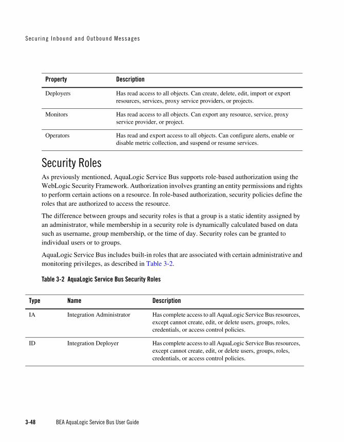
Secur ing Inbound and Outbound Messages
3-48 BEA AquaLogic Service Bus User Guide
Security RolesAs previously mentioned, AquaLogic Service Bus supports role-based authorization using the WebLogic Security Framework. Authorization involves granting an entity permissions and rights to perform certain actions on a resource. In role-based authorization, security policies define the roles that are authorized to access the resource.
The difference between groups and security roles is that a group is a static identity assigned by an administrator, while membership in a security role is dynamically calculated based on data such as username, group membership, or the time of day. Security roles can be granted to individual users or to groups.
AquaLogic Service Bus includes built-in roles that are associated with certain administrative and monitoring privileges, as described in Table 3-2.
Table 3-2 AquaLogic Service Bus Security Roles
Deployers Has read access to all objects. Can create, delete, edit, import or export resources, services, proxy service providers, or projects.
Monitors Has read access to all objects. Can export any resource, service, proxy service provider, or project.
Operators Has read and export access to all objects. Can configure alerts, enable or disable metric collection, and suspend or resume services.
Property Description
Type Name Description
IA Integration Administrator Has complete access to all AquaLogic Service Bus resources, except cannot create, edit, or delete users, groups, roles, credentials, or access control policies.
ID Integration Deployer Has complete access to all AquaLogic Service Bus resources, except cannot create, edit, or delete users, groups, roles, credentials, or access control policies.

Access Cont ro l
BEA AquaLogic Service Bus User Guide 3-49
For information on how to configure users and groups, see Security Configuration in Using the AquaLogic Service Bus Console.
For more information about security roles, see Users, Groups, and Security Roles, in Securing WebLogic Resources.
Role-Based Access in AquaLogic Service Bus ConsoleTable 3-4 shows the matrix of the actions that can be carried out in the console modules by users in the various roles:
Table 3-3 AquaLogic Service Bus Roles and Types
Note: Permission to perform an action is indicated by a check mark ( ) in the Role Type columns in the table.
In the Security Configuration section of this table, there are no check marks for create, edit, and delete users, groups, and roles, or for create, edit, view, and delete credentials and access control policies. The reason for this is that only WLS Administrators have access to these functions. Note that the WLS Administrator role is different from the IntegrationAdministrator role.
IM Integration Monitor Has read access to all AquaLogic Service Bus resources.
IO Integration Operator This group has the following privileges:
• Has read access to all AquaLogic Service Bus resources
• Has access to create, view, edit and delete alert rules
• Has access to session management, including create, commit, discard and undo of sessions.
Type Name Description
Role Type
Integration Administrator IA
Integration Deployer ID
Integration Monitor IM
Integration Operator IO

Secur ing Inbound and Outbound Messages
3-50 BEA AquaLogic Service Bus User Guide
Table 3-4 Role-Based Access in AquaLogic Service Bus Console
Console Module Actions Role Types
IA IO IM ID
Monitoring Dashboard
Services View Statistics
Alerts View Alerts
Message Reports View Message Reports
Reporting
Message Reports View Message Reports
Resource Browser
Services
Business Service Definition
Create Service
View Service
Edit Service
Delete Service
Proxy Service Definition
Create Proxy Service
View Proxy Service
Edit Proxy Service
Delete Proxy Service
Alert Rule Create Alert Rule

Access Cont ro l
BEA AquaLogic Service Bus User Guide 3-51
View Alert Rule
Edit Alert Rule
Delete Alert Rule
Operational Configuration
View...
Create/Update/Delete
WS-Policies Create WS-Policy
View WS-Policy
Edit WS-Policy
Delete WS-Policy
WSDLs Create WSDLs
View WSDLs
Edit WSDLs
Delete WSDLs
XML Schemas Create XML Schemas
View XML Schemas
Edit XML Schemas
Delete XML Schemas
XQuery Transformations
Create XQuery
View XQuery
Edit XQuery
Console Module Actions Role Types
IA IO IM ID

Secur ing Inbound and Outbound Messages
3-52 BEA AquaLogic Service Bus User Guide
Delete XQuery
XSLTs Create XSLT
View XSLT
Edit XSLT
Delete XSLT
MFLs Create MFL
View MFL
Edit MFL
Delete MFL
Proxy Service Providers
Create Proxy Service Provider
View Proxy Service Provider
Edit Proxy Service Provider
Delete Proxy Service Provider
Project Explorer
Projects Create Project
View Project
Edit Project
Delete Project
Folders Create Folder
View Folder
Console Module Actions Role Types
IA IO IM ID

Access Cont ro l
BEA AquaLogic Service Bus User Guide 3-53
Edit Folder
Delete Folder
Security Configuration
Users Create User
View User
Edit User
Delete User
Groups Create Group
View Group
Edit Group
Delete Group
Roles Create Role
View Role
Edit Role
Delete Role
Credentials Create Credential
View Credential
Edit Credential
Delete Credential
Access Controls Create Policy
Console Module Actions Role Types
IA IO IM ID

Secur ing Inbound and Outbound Messages
3-54 BEA AquaLogic Service Bus User Guide
View Policy
Edit Policy
Delete Policy
System Administration
Configuration Repository
Import Resources
Export Resources
Global Settings View State
Edit State
Tracing Configuration View Tracing
Edit Tracing
UDDI UDDI Configuration
Import from UDDI
Publish to UDDI
Change Center
Session Management Begin Session
View Session
Undo Task
Console Module Actions Role Types
IA IO IM ID

Access Cont ro l
BEA AquaLogic Service Bus User Guide 3-55
CredentialsYou can configure AquaLogic Service Bus with the credentials it needs to securely interact with clients and business services. AquaLogic Service Bus credentials are built on top of the WebLogic Security Framework. To set up credentials, you use the Credentials section of the Security Configuration module in the AquaLogic Service Bus Console. For information on using the console to configure credentials, see Security Configuration in the Using the AquaLogic Service Bus Console. AquaLogic Service Bus supports the following types of credentials:
Username and password
Key pairs
This section includes information on the following topics:
Service Accounts
Proxy Service Providers
Configuring Credentials
Configuring Proxy Service Access Control
Service AccountsA service account is an alias resource for a username and password. AquaLogic Service Bus uses service accounts to provide authentication when connecting to a business service or server. For example, when configuring FTP transport-level security for a business service, you may need to provide a username and password to authenticate to the FTP server.
Service accounts are used when configuring transport protocols for business services. They are also used for outbound Web Services Security Username Token authentication. Before configuring your business services, you have to define a service account. You can use the same service account for multiple purposes. After you define a service account, you can specify the
Discard Session
Commit Session
Console Module Actions Role Types
IA IO IM ID

Secur ing Inbound and Outbound Messages
3-56 BEA AquaLogic Service Bus User Guide
associated username and password to the service account using the Credentials section of the Security Configuration module in the AquaLogic Service Bus Console. For more information, see “Configuring Credentials” on page 3-57.
For information on how to create a service account, see Service Accounts in the Using the AquaLogic Service Bus Console.
Proxy Service ProvidersSome security scenarios require the use of PKI key-pair credentials. A key-pair credential is a private key and certificate pair. The certificate includes the public key corresponding to the private key. Whenever a proxy service must have access to PKI key-pairs, a proxy service must be assigned to the proxy. You must configure a PKI credential mapper in your security realm before using proxy service providers. No PKI credential mapping provider is configured out-of-the-box in ALSB 2.1 domains. For more information, see “Configuring a PKI Credential Mapping Provider” in Configuring WebLogic Security Providers in Securing WebLogic Server.
Warning: After adding or deleting a security provider, such as a PKI credential mapper, you must reboot the server for the security changes to take effect.
The proxy service obtains PKI credentials from the proxy service provider when needed. For example, to open an HTTPS connection with client-certificate authentication, the proxy service retrieves the SSL client key-pair from the proxy service provider. Multiple proxy services can use the same proxy service provider. You can assign different PKI key-pair credentials to a proxy service provider for different purposes. Proxy service providers supply credentials for the following purposes:
SSL Client Authentication—used for outbound transport-level security. For a description of CLIENT CERT authentication, see “Outbound HTTPS Transport-Level Security” on page 3-18.
Digital Signature—provides outbound message integrity. This key pair is used with WS-Security when a proxy service is required by WS-Policy statements to sign one or more parts of a SOAP envelope.
Encryption—provides inbound message confidentiality. This key-pair is used with WS-Security when a proxy service is required by WS-Policy statements to decrypt one or more parts of a SOAP envelope.
X.509 authentication—this key pair is used for outbound WS-Security when a business service requires X.509 authentication.

Access Cont ro l
BEA AquaLogic Service Bus User Guide 3-57
Before configuring security for a proxy service, you first need to create a proxy service provider. This allows you to designate the proxy service provider while configuring the proxy service. After you activate the proxy service in the AquaLogic Service Bus Console, you can associate PKI credentials to the proxy service provider using the Credentials section of the Security Configuration module. For more information, see “Configuring Credentials” on page 3-57.
For more information on how to create a proxy service provider, see Proxy Service Providers in the Using the AquaLogic Service Bus Console. For information about credential mapping providers, see Security Providers in Understanding WebLogic Security and “WebLogic Server Prerequisites” on page 3-9.
Configuring CredentialsCredentials are persisted in security providers and not in the repository governed by the AquaLogic Service Bus sessions. This means that credentials are independent of the session in which the associated service account or proxy service provider are created. Be sure to follow these guidelines:
If you want to configure AquaLogic Service Bus to access credentials, use the following order:
a. Create the service account or proxy service provider.
b. Activate the session. This makes the service account or proxy service provider visible in the Credentials section.
c. After the session is activated, define the credential for the service account or proxy service provider.
If you want to delete, rename, or move a service account or proxy service provider:
a. Before activating a session, delete the credential from the credentials section of the AquaLogic Service Bus Console.
b. After the credential is deleted, activate a session to delete, rename, or move the service account or proxy service provider.
For information on how to perform the steps described in this section, see Service Accounts, Proxy Service Providers, and Using the Change Center in the Using the AquaLogic Service Bus Console.

Secur ing Inbound and Outbound Messages
3-58 BEA AquaLogic Service Bus User Guide
Configuring Proxy Service Access ControlYou can configure transport-level access control for HTTP and HTTPS proxy services. You can also configure access control at the message-level for any WS-Security active intermediary proxy service. To configure access control, you must assign an access control policy to the proxy service, either at the transport-level or message-level (or both).
The default transport-level and message-level access control policy for all proxy services is to allow access to all requests. You must assign an access control policy to the proxy service to protect it.
Note: No support for access control to JMS, FTP, email or file proxy services exists. These protocols have protocol-independent mechanisms to protect the underlying resources.
An access control policy is an association between a WebLogic resource and one or more users, groups, or security roles. A security policy protects the WebLogic resource against unauthorized access. Access control policies are boolean expressions assigned to specific resources. When there is an attempt to access the resource, the expression is evaluated. The expression consists of one or more conditions joined by boolean operators, such as a role (operator) and access time (8am to 5pm). For more information about access control policies, see Security Fundamentals in Understanding WebLogic Security and Components of a Security Policy: Policy Conditions, Expressions, and Statements in Securing WebLogic Resources.
You configure transport-level and message-level access control policies in the AquaLogic Service Bus Console. Additionally, you can assign access control policies to WebLogic resources in theWebLogic Server Administration Console. For more information, see Security Policies in Securing WebLogic Resources and Manage Security Policies in the WebLogic Server Administration Console Online Help.
Access control policies are persisted in authorization providers and not in the repository governed by the AquaLogic Service Bus sessions. Subsequently, proxy service access-control policies are independent of the session in which the associated proxy service is created. If you make changes to your proxy services, be sure to follow these guidelines:
If you want to delete a proxy service:
1. Create a session if you have not already done so.
2. Delete any transport security policy assigned to the proxy URL.
3. Delete any service security policies assigned to the proxy or its operations.
4. Delete the proxy service.

Secur ing AquaLogi c Se rv i ce Bus fo r a P roduc t ion Env i ronment
BEA AquaLogic Service Bus User Guide 3-59
5. Activate the session.
If you want to move or rename a proxy service:
1. Create a session if you have not already done so.
2. Delete any service security policies assigned to the proxy service or its operations.
3. Move or rename the proxy service.
4. Active the session. The proxy service will now be moved or renamed.
5. Locate the renamed or moved proxy service and re-assign any service security policies deleted in step 2.
If you want to change the proxy service URL:
1. Create a session if you have not already done so.
2. Delete any transport security policy assigned to the proxy service’s URL.
3. Edit the proxy service’s URL.
4. Active the session.
5. Re-assign the transport security policy deleted in step 2.
If you want to rename a proxy service operation:
1. Create a session if you have not already done so.
2. Delete any service security policy assigned to the operation you are renaming.
3. Change the operation name.
4. Active the session.
5. Re-assign the service security policy deleted in step 2 to the new operation.
Securing AquaLogic Service Bus for a Production EnvironmentTo prepare an AquaLogic Service Bus installation for production, you must pay special attention to your security needs. The following list outlines some of the tasks you need to perform:
Read and follow the guidelines in Securing a Production Environment in the WebLogic Server documentation.

Secur ing Inbound and Outbound Messages
3-60 BEA AquaLogic Service Bus User Guide
Create user accounts for the AquaLogic Service Bus administrators and assign them to one or more of the following groups as appropriate: IntegrationAdministrators, IntegrationOperators, IntegrationMonitors, and IntegrationDeployers. For more information, see “Role-Based Access in AquaLogic Service Bus Console” under “Overview of Security Configuration” in Security Configuration in Using the AquaLogic Service Bus Console.
In your file system, configure access control to the directory that contains AquaLogic Service Bus configuration data. This is the sbconfig directory under the domain root. For example:
C:\bea\user_projects\domains\base_domain\sbconfig
In your file system, configure access control to the directories used by the FTP, file, and email transports.
If necessary, configure access control to the JMS resources used by your AquaLogic Service Bus installation.
BEA AquaLogic Service Bus User Guide 4-1
C H A P T E R 4
Using the Test Console
The BEA AquaLogic Service Bus Test Console is a browser-based test environment used to validate and test the design of your system. It is an extension of the AquaLogic Service Bus Console. You can configure the object of your test (proxy service, business service, XQuery, XSLT, MFL resource), execute the test, and view the results in the console. In some instances you can trace through the code and examine the state of the message at specific trace points. Design time testing helps isolate design problems before you deploy a configuration to a production environment. The test console can test specific parts of your system in isolation and it can test your system as a unit.
The Test Console can be invoked to test any proxy service or business service and certain resources used by these services. You can also do in-line XQuery testing.
You can invoke the test console in a number of ways in the AquaLogic Service Bus Console, depending on what part of your process you want to test. You can invoke the test console from:
The Project Explorer
The Resource Browser
The XQuery Editor
You can run and test a proxy service that makes a call to another proxy service or business service and vice versa. You can test the resources used by your services. When testing services you must be aware of the information that is passing from the test console to the service and vice versa.

Using the Tes t Conso le
4-2 BEA AquaLogic Service Bus User Guide
FeaturesThe test console supports the following features:
Testing proxy services
Testing business services
Testing resources
Testing in-line XQueries
Tracing the message through the message flow (for proxy services only)
PrerequisitesTo use the test console:
You must have AquaLogic Service Bus running and you must have activated the session that contains the resource you want to test.
You must disable the pop-up blockers in your browser for the inline XQuery testing to work. Note that if you have toolbars in the Internet Explorer browser, this may mean disabling pop-up blockers from under the options menu as well as for all toolbars that are configured to block them. Inline XQuery testing is done only in the design time environment (in an active session).
Testing Proxy ServicesYou must have activated a session to test a proxy service. You can test a proxy service from the Resource Browser or Project Explorer. You can test the following types of proxy services:
Any XML
Any SOAP
Messaging
XML
SOAP

Tes t ing P roxy Se rv i ces
BEA AquaLogic Service Bus User Guide 4-3
Direct CallsA Direct Call is used to test a proxy service that is collocated in the AquaLogic Service Bus domain. Using the Direct Call option, messages are sent directly to the proxy service, bypassing the transport layer. When you employ the Direct Call option, tracing is turned on by default, allowing you to diagnose and troubleshoot a message flow in the test console. By default, testing of proxy services is done using the Direct Call option.
When you use the Direct Call option to test a proxy service, the configuration data you input to the test console must be that which is expected by the proxy service from the client that invokes it. In other words, the test console plays the role of the client invoking the proxy service.
The following figure illustrates a direct call. Note that the message bypasses the transport layer; it is delivered directly to the proxy service (P1).
Figure 4-1 Direct Call to Test a Proxy Service
A Direct Call strategy is best suited for testing proxy services’ internal message flow logic. Your test data should simulate the expected message state at the time it is dispatched. Use this test approach in conjunction with setting custom (inbound) transport headers in the test console’s Transport section to accurately simulate the service call.
Indirect CallsWhen you test a proxy service with an indirect call (that is, when the Direct Call option is not checked), the message is sent to the proxy service through the transport layer. The transport layer performs manipulation of message headers or metadata as part of the test. The effect is to invoke a proxy service to proxy service invocation run-time path.

Using the Tes t Conso le
4-4 BEA AquaLogic Service Bus User Guide
The following figure illustrates an indirect call. Note that the message is first processed through the transport layer and is subsequently delivered to the proxy service (P1).
Figure 4-2 Indirect Call to Test a Proxy Service
This testing strategy is recommended when testing a proxy service to proxy service interface when both services run in the same JVM. Use this test approach in conjunction with setting custom (outbound) transport headers in the test console’s Transport panel to accurately simulate the service call. To learn more about the Transport settings in the test console, see “Test Console Transport Settings” on page 4-22.
Using the indirect call, the configuration data you input to the test is the data being sent from a proxy service (for example from a Route Node or a Service Callout action of another proxy service). In the indirect call scenario, the test console plays the role of the proxy service that routes to, or makes a callout to, another service.
HTTP RequestsWhen you test proxy services, the test console never sends a HTTP request over the network, therefore transport-level access control is not applied.
(This transport-level access control is achieved through the Web Application layer—in other words, even in the case that an indirect call is made through the AquaLogic Service Bus Console transport layer, an HTTP request is not sent over the network and this transport-level access control is not applied.) For information about the AquaLogic Service Bus Console architecture, see Overview in BEA AquaLogic Service Bus Concepts and Architecture.
For information about transport settings, see “Understanding How the Run Time Uses the Transport Settings in the Test Console” on page 4-24.

Test ing Bus iness Se rv ices
BEA AquaLogic Service Bus User Guide 4-5
Testing Business ServicesYou must have activated a session to test services. You can test the following types of business services:
Any XML
Any SOAP
Messaging
XML
SOAP
When testing business services, the messages are always routed through the transport layer. The Direct Calls option is not available. The configuration data that you provide to the test console to test the service is that which represents the state of the message that is expected to be sent to that business service—for example from a Route Node or a Service Callout action of a proxy service. The test console is in the role of the caller proxy service when you use it to test a business service.
Transport SecurityWhen using the test console to test HTTP(S) business services with BASIC authentication, the test console authenticates with the username/password from the service account of the business service. Similarly, when testing JMS, email, or FTP business services that require authentication, the test console authenticates with the service account associated with the business service.
Recommended Approaches to Testing Proxy and Business Services
In the scenario depicted in the following figure, a client invokes the proxy service (P1). The message flow invokes business service B1, then proxy service P2, then proxy service P3 before returning a message to the client. Interfaces are identified by number.

Using the Tes t Conso le
4-6 BEA AquaLogic Service Bus User Guide
Figure 4-3 Test Scenario Example
There are many valid test strategies for this scenario. The following are recommended test strategies:
It is recommended that you complete the testing of interfaces other than the client interface to a given proxy service before you test the client call. In the sample scenario illustrated in the preceding figure, this means that you complete the testing of interfaces 1 through 4 first, then test interface 5. In this way, the message flow logic for the proxy service (P1) can be iteratively changed and tested (via interface 5) knowing that the other interfaces to the proxy service function correctly.
It is recommended that all the XQuery expressions in a message flow be validated and tested prior to a system test. In the preceding figure, interface 1 refers to XQuery expression tests.

Trac ing P rox y Se rv i ces Us ing the Tes t Console
BEA AquaLogic Service Bus User Guide 4-7
Proxy service to business service (interface 2 in the preceding figure) is tested using a indirect call. In other words, the messages are routed through the transport layer.
Proxy service to proxy service tests (Interfaces 3 and 4 in the preceding figure) are tested using an indirect call. In other words, disable the Direct Call option, which means that during the testing, the messages are routed through the transport layer.
Your final system test simulates the client invoking the proxy service P1. This test is represented by interface 5 in the preceding figure.
Test interface 5 with a Direct Call. In this way, during the testing, the messages bypass the transport layer. Tracing is automatically enabled with a Direct Call.
It is recommended that the message state be saved after executing successful interface tests to facilitate future troubleshooting efforts on the system. Testing interface 5 is in fact a test of the complete system and knowing that all other interfaces in the system work correctly helps narrow the troubleshooting effort when system errors arise.
Tracing Proxy Services Using the Test ConsoleTracing the message through a proxy service involves examining the message context and outbound communications at various points in the message flow. The points at which the messages are examined are predefined by AquaLogic Service Bus. AquaLogic Service Bus defines tracing for stages, error handlers and route nodes.
For each stage, the trace includes the changes that occur to the message context and all the services invoked during the stage execution. The following information is provided by the trace:
New variables— —the names of all new variables and their value (values can be seen by clicking +)
Deleted variables— —the names of all deleted variables
Changed variables— —the names of all variables for which the value changed. The new value is visible by clicking on the + sign).
Publish—every publish call is listed. For each publish call, the trace includes the name of the service invoked, and the value of the outbound, header, body and attachment variables.
Service Callout—every Service Callout is listed. For each Service Callout, the trace includes the name of the service that is invoked, the value of the outbound variable, the

Using the Tes t Conso le
4-8 BEA AquaLogic Service Bus User Guide
value of the header, body, and attachment variables for both the request and response messages.
The trace contains similar information for Route Nodes as for stages. In the case of Route Nodes, the trace contains the following categories of information:
The trace for service invocations on the request path
The trace for the Routed Service
The trace for the service invocations on the response path
Changes made to the message context between the entry point of the route node (on the request path) and the exit point (on the response path)
Example: Testing and Tracing a Proxy ServiceThis example uses one of the proxy services in the example AquaLogic Service Bus domain as a basis of instruction.
To learn how to start the example domain and run the examples provided there, see BEA WebLogic Service Bus Samples. This example scenario uses the proxy service named loanGateway3, associated with the Validating a Loan Application example.
The message flow for loanGateway3 is represented in the following figure. The figure is annotated with the configuration for the validate loan application stage and the configuration for the route node.

Trac ing P rox y Se rv i ces Us ing the Tes t Console
BEA AquaLogic Service Bus User Guide 4-9
Figure 4-4 Message Flow for Proxy Service (LoanGateway3)
To test this proxy service in the AquaLogic Service Bus examples domain using the test console, complete the following procedure:
1. Start the AquaLogic Service Bus examples domain and load the samples data, as described see BEA WebLogic Service Bus Samples.
2. Log in to the AquaLogic Service Bus Console, then select Project Explorer and locate the LoanGateway3 proxy service.
3. Select the Launch Test Console icon for the LoanGateway3 proxy service. The Proxy Service Testing - LoanGateway3 page is displayed. Note that the Direct Call and the Include Tracing options are selected.
4. Edit the test XML provided to send the following message for the test.

Using the Tes t Conso le
4-10 BEA AquaLogic Service Bus User Guide
Listing 4-1 Test Message for LoanGateway3
<loanRequest xmlns:java=”java.normal.client”>
<java:Name>Name_4</java:Name>
<java:SSN>SSN_11</java:SSN>
<java:Rate>4.9</java:Rate>
<java:Amount>2500</java:Amount>
<java:NumOfYear>20.5</java::NumOfYear>
<java:Notes>Name_4</java:Notes>
</loanRequest>
5. Click Execute.
The results page is displayed. Scroll to the bottom of the page to see the tracing results in the Invocation Trace panel.
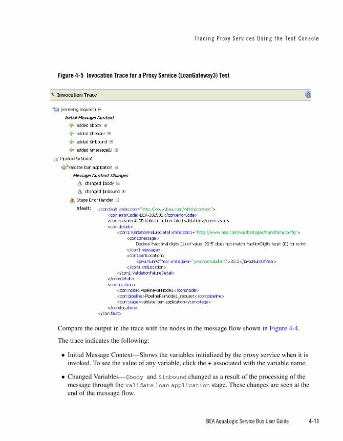
Trac ing P rox y Se rv i ces Us ing the Tes t Console
BEA AquaLogic Service Bus User Guide 4-11
Figure 4-5 Invocation Trace for a Proxy Service (LoanGateway3) Test
Compare the output in the trace with the nodes in the message flow shown in Figure 4-4.
The trace indicates the following:
Initial Message Context—Shows the variables initialized by the proxy service when it is invoked. To see the value of any variable, click the + associated with the variable name.
Changed Variables—$body and $inbound changed as a result of the processing of the message through the validate loan application stage. These changes are seen at the end of the message flow.

Using the Tes t Conso le
4-12 BEA AquaLogic Service Bus User Guide
The contents of the fault context variable ($fault) is shown as a result of the Stage Error Handler handling the validation error. (The non-integer value (20.5) you entered for the <java:NumOfYear> element in Listing 4-1 caused the validation error in this case.)
For more information about this loan application scenario, see Tutorial 3: Validating a Loan Application in BEA AquaLogic Service Bus Tutorials.
It is left as an exercise to the reader to test the service using different input parameters, or to change the behavior of the message flow in the AquaLogic Service Bus Console Project Explorer, and run the test again to view the results.
Testing ResourcesYou can test resources inside an active session or from outside a session. You can test the following resources:
MFL
XSLT
XQuery
MFLA Message Format Language (MFL) document is a specialized XML document used to describe the layout of binary data.
MFL resources support the following transformations:
XML to Binary - there is one required input (XML) and one output (Binary).
Binary to XML - there is one required input, Binary, and one output, XML.
Each transformation only accepts one input and provides a single output.
The following example describes an XML input file to be tested in the test console. When you invoke the test console to test the MFL file, sample XML data is generated. Execute the test using the sample XML—in this case, a successful test results in the transformation of the message content of the input XML document in to binary format. The following Example section describes the MFL, the test XML, and the data resulting from the test.

Tes t ing Resources
BEA AquaLogic Service Bus User Guide 4-13
ExampleThe following listing is an example MFL file.
Listing 4-2 Contents of an MFL File
<?xml version='1.0' encoding='windows-1252'?>
<!DOCTYPE MessageFormat SYSTEM 'mfl.dtd'>
<MessageFormat name='StockPrices' version='2.01'>
<StructFormat name='PriceQuote' repeat='*'>
<FieldFormat name='StockSymbol' type='String' delim=':'
codepage='windows-1252'/>
<FieldFormat name='StockPrice' type='String' delim='|'
codepage='windows-1252'/>
</StructFormat>
</MessageFormat>
The XML input generated by the test console to test the MFL file in the Listing 4-2 is described in the following listing.
Listing 4-3 Test Console XML Input
<StockPrices>
<PriceQuote>
<StockSymbol>StockSymbol_31</StockSymbol>
<StockPrice>StockPrice_17</StockPrice>
</PriceQuote>
</StockPrices>
In the test console, click Execute to run the test—the result is the Stock symbol and the stockPrice in binary format as shown in the following listing.

Using the Tes t Conso le
4-14 BEA AquaLogic Service Bus User Guide
Listing 4-4 MFL Test Console Results
00000000: 53 74 6F 63 6B 53 79 6D 62 6F 6C 5F 33 31 3A 53StockSymbol_31:S
00000010: 74 6F 63 6B 50 72 69 63 65 5F 31 37 7C .. .. ..tockPrice_17|...
XSLTeXtensible Stylesheet Language Transformation (XSLT) describes XML-to-XML mappings in AquaLogic Service Bus. You can use XSL Transformations when you edit XQuery expressions in the message flow of proxy services
To test an XSLT resource, you must supply an input XML document. The test console displays the output XML document as a result of the test. You can create parameters in your document to assist with a transformation. XSLT parameters accept either primitive values or XML document values. You cannot identify the types of parameters from the XSL transformation. In the Input and parameters section of the XSLT Resource Testing page in the test console, you must provide the values to bind to the XSLT parameters defined in your document.
XQueryXQuery uses the structure of XML intelligently to express queries across different kinds of data, whether physically stored in XML or viewed as XML.
An XQuery transformation can take multiple inputs and returns one output. The inputs expected by an XQuery transformation are variable values to bind to each of the XQuery external variables defined. The value of an XQuery input variable can be a primitive value (string, integer, date), an XML document, or a sequence of the previous types. The output value can be primitive value (string, integer, date), an XML document, a sequence of the previous types.
XQuery is a typed language—every external variable is given a type. The types can be categorized into the following groups:
Simple/primitive type—string, int, float, and so on.
XML nodes
Untyped
In the test console, a single-line edit box is displayed if the expected type is a simple type. A multiple-line edit box is displayed if the expected data is XML. A combination input is used when

Tes t ing Resources
BEA AquaLogic Service Bus User Guide 4-15
the variable is not typed. The test console provides the following field in which you can declare the variable type: [] as XML. Input in the test console is rendered based on the type. This makes it easy to understand the type of data you must enter.
For example, the following figure shows an XQuery with three variables: int, XML, and undefined type.
Figure 4-6 Input to the XQuery Test
In the Test Console, all three variables are listed in the Variables section. By default, for the untyped variable XML is checked as it is the most usual case. You must configure these variables.
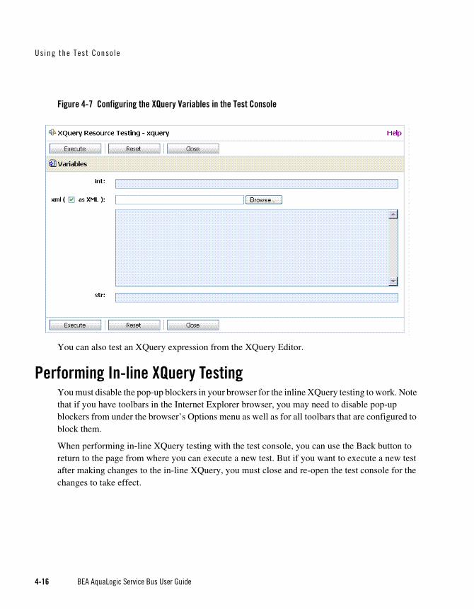
Using the Tes t Conso le
4-16 BEA AquaLogic Service Bus User Guide
Figure 4-7 Configuring the XQuery Variables in the Test Console
You can also test an XQuery expression from the XQuery Editor.
Performing In-line XQuery TestingYou must disable the pop-up blockers in your browser for the inline XQuery testing to work. Note that if you have toolbars in the Internet Explorer browser, you may need to disable pop-up blockers from under the browser’s Options menu as well as for all toolbars that are configured to block them.
When performing in-line XQuery testing with the test console, you can use the Back button to return to the page from where you can execute a new test. But if you want to execute a new test after making changes to the in-line XQuery, you must close and re-open the test console for the changes to take effect.

Tes t i ng Se rv ices Wi th Web Serv i ce Secu r i t y
BEA AquaLogic Service Bus User Guide 4-17
Testing Services With Web Service SecurityThe test console supports testing proxy services and business services protected with Web Service Security (WSS). A SOAP service is protected with WSS if it has WS-Policies with WS-Security assertions assigned to it. Specifically, a service operation is protected with WS-Security if the operation’s effective request and/or response WS-Policy includes WS-Security assertions. WS-Policies are assigned to a service by a mechanism called WS-PolicyAttachment. See “Web Services Policy Attachment” on page 3-35. Note that an operation may have both a request policy and a response policy.
When an operation has a request WS-Policy or response WS-Policy, the message exchange between the test console and the service is protected by the mechanisms of WS-Security. According to the operation’s policy, the test service digitally signs and/or encrypts the message (more precisely, parts of the message) and includes any applicable security tokens. The input to the digital signature and encryption operations is the clear-text SOAP envelope specified by the user as described in “Configuring Proxy Service Test Data” and “Configuring Business Service Test Data” in Test Console in the BEA AquaLogic Service Bus User Guide.
Similarly, the service processes the response according to the operation’s response policy. The response may be encrypted or digitally signed. The test service then processes this response and decrypts the message and/or verifies the digital signature.
The test console (Security panel) displays fields used for testing services with WS-Security: Service Provider, Username and Password.
Figure 4-8 Security Panel in Test Console
If you specify a proxy service provider in the test console, all client-side PKI key-pair credentials required by WS-Security are retrieved from the proxy service provider. For more information, see “Proxy Service Providers” on page 3-56. You use the username and password fields when an operation’s request policy specifies an Identity assertion and Username Token is one of the supported token types. For more information, see “Web Service Policy” on page 3-33.
The Service Provider, Username, and Password fields are displayed whenever the operation has a request or response policy. Whether the values are required depends on the actual request and response policies.

Using the Tes t Conso le
4-18 BEA AquaLogic Service Bus User Guide
The following table describes the different scenarios.
Table 4-1 Digital Signature and Encryption Scenarios
Scenario Is Proxy Service Provider Required?
The request policy has a Confidentiality assertion. No. The test service encrypts the request with the service’s public key. When testing a proxy service, the test service automatically retrieves the public key from the encryption certificate assigned to the proxy service provider of the proxy service.
When testing a business service, the encryption certificate is embedded in the WSDL of the business service. The test service automatically retrieves this WSDL from the WSDL repository and extracts the encryption certificate from the WSDL.
The response policy has a Confidentiality assertion.
Yes. In this scenario, the operation policy requires the client to send its certificate to the service. The service will use the public key from this certificate to encrypt the response to the client. A proxy service provider must be specified and must have an associated encryption credential.
If both request and response encryption are supported, different credentials must be used. For more information, see “Client Request and Proxy Service Response” on page 3-26 and “About Outbound Web Services Security” on page 3-30.

Tes t i ng Se rv ices Wi th Web Serv i ce Secu r i t y
BEA AquaLogic Service Bus User Guide 4-19
Table 4-2 Identity Policy Scenarios. It is Assumed the Policy has an Identity Assertion
The request policy has an Integrity assertion. Yes. The client must sign the request. A proxy service provider must be specified and must have an associated digital signature credential.
Furthermore, if this is a SAML holder-of-key integrity assertion, a username and password is needed in addition to the proxy service provider.
The response policy has an Integrity assertion. No. In this case, the policy specifies that the service must sign the response. The service signs the response with its private key.The test console simply verifies this signature.
When testing a proxy service, this is the private key associated to the proxy service provider’s digital signature credential for the proxy service.
When testing a business service, the service signing key-pair is configured in a product-specific way on the system hosting the service.
In the case that the current security realm is configured to do Certificate Lookup and Validation, then the certificate that maps to the proxy service provider must be registered valid in the certificate lookup and validation framework.
For more information on Certificate Lookup and Validation, see ''Configuring the Credential Lookup and Validation Framework” in Configuring WebLogic Security Providers in Securing WebLogic Server.
Supported Token Types1
Description Comments
UNT The service only accepts WSS username tokens
The user must specify a username and password in the security section.
X.509 The service only accepts WSS X.509 tokens
The user must specify a proxy service provider in the security section and the proxy service provider must have an associated WSS X.509 credential.
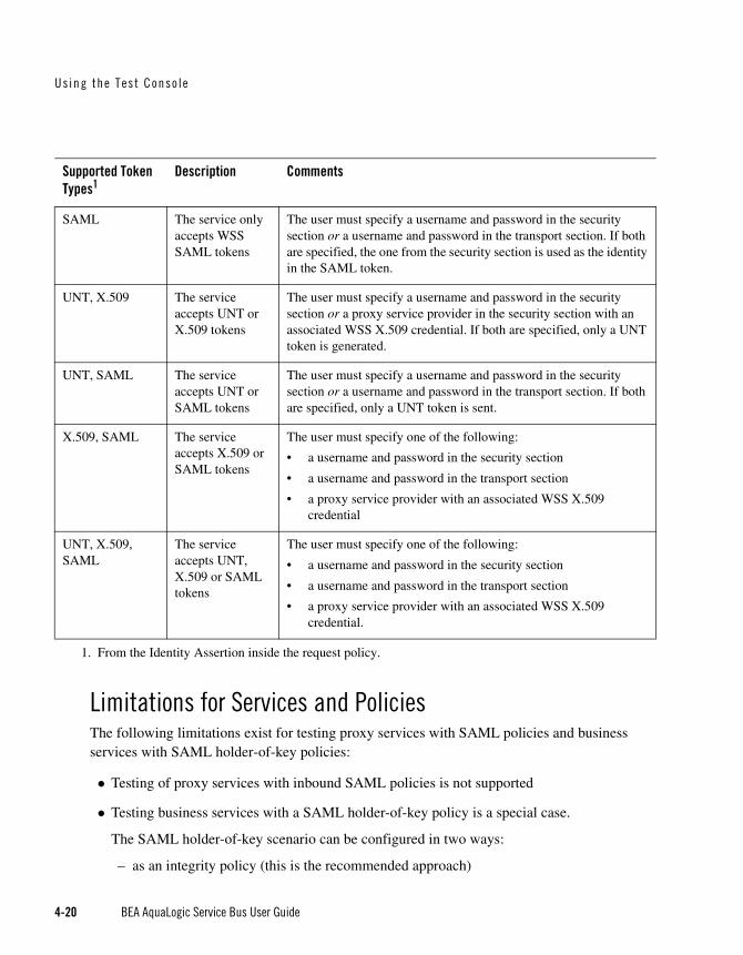
Using the Tes t Conso le
4-20 BEA AquaLogic Service Bus User Guide
Limitations for Services and PoliciesThe following limitations exist for testing proxy services with SAML policies and business services with SAML holder-of-key policies:
Testing of proxy services with inbound SAML policies is not supported
Testing business services with a SAML holder-of-key policy is a special case.
The SAML holder-of-key scenario can be configured in two ways:
– as an integrity policy (this is the recommended approach)
SAML The service only accepts WSS SAML tokens
The user must specify a username and password in the security section or a username and password in the transport section. If both are specified, the one from the security section is used as the identity in the SAML token.
UNT, X.509 The service accepts UNT or X.509 tokens
The user must specify a username and password in the security section or a proxy service provider in the security section with an associated WSS X.509 credential. If both are specified, only a UNT token is generated.
UNT, SAML The service accepts UNT or SAML tokens
The user must specify a username and password in the security section or a username and password in the transport section. If both are specified, only a UNT token is sent.
X.509, SAML The service accepts X.509 or SAML tokens
The user must specify one of the following:
• a username and password in the security section
• a username and password in the transport section
• a proxy service provider with an associated WSS X.509 credential
UNT, X.509, SAML
The service accepts UNT, X.509 or SAML tokens
The user must specify one of the following:
• a username and password in the security section
• a username and password in the transport section
• a proxy service provider with an associated WSS X.509 credential.
1. From the Identity Assertion inside the request policy.
Supported Token Types1
Description Comments

Tes t i ng Se rv ices Wi th Web Serv i ce Secu r i t y
BEA AquaLogic Service Bus User Guide 4-21
– as an identity policy
In both cases the user must specify a username and password—the SAML assertion will be on behalf of this user. If SAML holder-of-key is configured as an integrity policy, the user must also specify a proxy service provider. The proxy service provider must have a digital signature credential assigned to it. This case is special because this is the only case where a username and password must be specified even if there is not an identity policy.
Note: After executing a test in the test console, the envelope generated with WSS is not always a valid envelope—the results page in the test console includes white spaces for improved readability. That is, the secured SOAP message is displayed printed with extra white spaces. Because white spaces can affect the semantic of the document, this SOAP message cannot always be used as the literal data. For example, digital signatures are white-space sensitive and can become invalid.

Using the Tes t Conso le
4-22 BEA AquaLogic Service Bus User Guide
Test Console Transport SettingsThe transport panel in the test console provides the functionality to specify the metadata and transport headers for messages in your test system. The following figure shows an example of a Transport panel on the test console.
Figure 4-9 Transport Panel in the Test Console
The preceding figure displays an example of the transport panel for a given service—in this case, a WSDL-based proxy service.
You can set the metadata and the transport headers in the message flow of a proxy service. In doing this, you influence the actions of the outbound transport. You can test the metadata, the message, and the headers so that you can see the output you get in the pipeline. The fields that are displayed in the Transport panel when testing a proxy service represent those headers and

Test Consol e T ranspo r t Se t t ings
BEA AquaLogic Service Bus User Guide 4-23
metadata that are available in the pipeline. The test console cannot filter the fields it presents depending on the proxy service. The same set of transport parameters are displayed on the page for every HTTP-based request.
The Username and Password fields are used to implement basic authentication for the user that is running the proxy service. The Username and Password fields are not specifically transport related.
Metadata fields are grouped in the Transport panel, below the Username and Password fields and above the group of transport header fields. The fields displayed are based on the transport type of the service. Certain fields are pre populated in the test console depending on the operation selection algorithm you selected for the service when you defined it.
For example, in the case of the transport panel displayed in Figure 4-9, the SOAPAction header field is populated with “http://example.orgprocessLoanApp”. This value was taken from the service definition (the selection algorithm selected for this proxy service was SOAPAction Header). For more information about the selection algorithms, see “Adding a Proxy Service” in Proxy Services in Using the AquaLogic Service Bus Console.
When you specify values for fields in the transport panel, be aware whether you opted to test the service using a direct or indirect call—see “Direct Calls” on page 4-3 and “Indirect Calls” on page 4-3—and specify the values according to whether the message will be processed through the transport layer or not.
When testing a proxy service with a direct call, the test data must represent the message as if it had been processed through the transport layer. That is, the test data should represent the message in the state expected at the point it leaves the transport layer and enters the service. When testing a proxy or business service, using an indirect call, the test data represents the data that is sent from a route node or a service callout. The test message is processed through the transport layer.
For information about specific headers and metadata and how they are handled by the test framework, see Understanding How the Run Time Uses the Transport Settings in the Test Console.

Using the Tes t Conso le
4-24 BEA AquaLogic Service Bus User Guide
About Security and TransportsWhen using the test console to test HTTP(S) business services with BASIC authentication, the test console authenticates with the username and password from the service account of the business service. Similarly, when testing JMS, email, or FTP business services that require authentication, the test console authenticates with the service account associated with the business service.
When you test proxy services, the test console never sends a HTTP request over the network. Therefore transport-level access control is not applied.
Understanding How the Run Time Uses the Transport Settings in the Test ConsoleThe test console allows you to specify header values and metadata. However, when the message is sent out, some headers and metadata may be modified or removed, and the underlying transport may in turn, ignore some of the headers and use its own values when the test is executed.
The following table describes the headers and metadata for which there are limitations when using the test console.
Table 4-3 Limitations to Transport Header and Metadata Values You Specify in the Test Console When Testing a Service
Transport Testing this Service Type
Description of Limitation Transport Headers Affected
HTTP(S)1 Proxy Service All transport headers and other fields you set are preserved at run time.
This is true whether or not the Direct Call option is set.
All
Business Service The AquaLogic Service Bus run time overrides any values you set for these parameters
• Content-Length
• Content-Type
• relative-URI
• client-host
• client-address

Test Consol e T ranspo r t Se t t ings
BEA AquaLogic Service Bus User Guide 4-25
JMS Proxy Service Direct Call
When the Direct Call option is used, all transport headers and other fields you set are preserved at run time
All
X Direct Call
When the Direct Call option is not used, the same limitations apply as for a transport header action configuration
See the limitations for JMS transport headers described in “Transport Headers” in Proxy Services: Actions in Using the AquaLogic Service Bus Console.
Business Service The same limitations apply as for a transport header action configuration
See the limitations for JMS transport headers described in “Transport Headers” in Proxy Services: Actions in Using the AquaLogic Service Bus Console.
EMail Proxy Service No limitations. In other words, any transport headers and other fields you set are honored by the run time. This is true whether or not Direct Call is specified.
Business Service The AquaLogic Service Bus run time overrides any values you set for these parameters
• Content-Type
File Proxy Service No limitations. In other words, any transport headers and other fields you set are
honored by the run time.2
Business Service
FTP Proxy Service No limitations. In other words, any transport headers and other fields you set are honored by the run time.
Business Service
Transport Testing this Service Type
Description of Limitation Transport Headers Affected

Using the Tes t Conso le
4-26 BEA AquaLogic Service Bus User Guide
1. When you test proxy services, the test console never sends a HTTP request over thenetwork, therefore transport-level access control is not applied.2. For example, in the case of FileName (Transport metadata)—the value you assign is used toappend to the output file name. For example,1698922710078805308-b3fc544.1073968e0ab.-7e8e-{$FileName}
BEA AquaLogic Service Bus User Guide 5-1
C H A P T E R 5
Monitoring
BEA AquaLogic Service Bus provides the capability to monitor and collect run-time information for systems operations purposes. AquaLogic Service Bus aggregates run-time statistics that you can view on a customizable Dashboard. The Dashboard allows you to monitor the health of the system and alerts you to problems in your messaging services. With this information, you can quickly and easily isolate and diagnose problems as they occur.
This chapter includes the following topics:
Monitoring Scenarios
About Monitoring
Service Summary
Server Summary
Alert Summary
Alert Rules
Monitoring ScenariosThe following describes some of the ways in which you can use AquaLogic Service Bus to check system operations and monitor messages.
Operational HealthThe Dashboard page in the AquaLogic Service Bus Console provides the ability to immediately view the state of all servers and monitored services. The Dashboard displays

Moni to r ing
5-2 BEA AquaLogic Service Bus User Guide
two pie charts, a table, and several links. The Service Summary pie chart shows the percentage of alerts according to their severity for all services that have alert rules defined and monitoring enabled for the last 30 minutes. The Server Summary pie chart shows the current status of every server in the AquaLogic Service Bus domain. Additionally, from the Server Summary panel, you can drill-down and view the domain logs, which are grouped according to severity.
In addition to the pie charts, these Summaries include a list of the most active services and critical servers. The list displays up to ten services in descending order of the most number of alerts. The most critical server list displays the ten most critical servers. This display is based on the health state of the running servers, as defined by the WebLogic Diagnostic Service. For more information about the WebLogic Diagnostic Service, see Configuring and Using the WebLogic Diagnostics Framework.
From each of the summaries, you can drill-down into more detail by clicking a specific area on a pie chart or by clicking one of the links on the page.
The default Alert Summary table shows the severity of the alert, when the alert occurred, the name of the corresponding service, and what alert rule was violated. Alerts are displayed by severity. You can customize, search, and scroll through this table.
Alert MonitoringWhen you log into the AquaLogic Service Bus Console, you see a list of alerts on the Dashboard. Each row of the table displays the information that you have configured, such as the severity, timestamp, and associated service. You notice that numerous alerts have been generated since your last viewing. To find the problem, you filter the alerts and discover that the Service Level Agreement (SLA) violation is due to errors produced by the Post-Trade Processing proxy service. SLAs are agreements that define the precise level of service expected by AquaLogic Service Bus business and proxy services.
Alternatively, attention to the problem involves an alert rule’s ability to send messages in the event of a SLA violation. In this case, you are notified by email of the alert rule violation. After receiving the emails, you look into the problem and discover that the errors are produced by the Post-Trade Processing proxy service.
To narrow the problem down, you can use the reporting module. This scenario is continued in “Message Tracking” on page 6-2.
Statistics MonitoringSuppose that you want to see how many messages in a particular service have processed successfully and how many have failed. To access this information, from the Dashboard, you access the Service Monitoring Summary page and filter the display for the relevant service. Besides displaying the number of messages that have successfully processed or

About Mon i to r ing
BEA AquaLogic Service Bus User Guide 5-3
failed, you can also see which project the service belongs to, the average execution time of message processing, and the number of alerts associated with the service. You can display monitoring statistics for the period of the current aggregration interval or you can display monitoring statistics for the period since you last reset statistics for this service or since you last reset statistics for all services.
Note: You use the Global Settings page in the System Administration module of the AquaLogic Service Bus Console to reset statistics. When you do this, make sure you are not in a WebLogic session on the WebLogic Server Administration Console.
Clicking the name of the service brings you to that service’s Service Monitoring Details page. This page provides additional information such as the minimum and maximum response times and the overall average time it takes for the service to execute a message, the success-failure ratio, the number of messages that have failed because of security or validation errors, and the number of messages associated with proxy service components (pipelines and route nodes). You can display this information for specific operations associated with the service. Again, you can display these statistics for the period of the current aggregration interval or you can display the statistics for the period since you last reset statistics for this service or since you last reset statistics for all services.
Verifying Service Level AgreementsYou are notified by email of a large number of execution-time SLA violations from the Trade Execution proxy service. To track down this problem, you log into the AquaLogic Service Bus Console. From the Dashboard, you drill into the service associated with the alerts and see that a pipeline operation that invokes an Avitek Web Service is unacceptably slow. After successfully renegotiating service-level characteristics with Avitek, you configure alert metrics to track Avitek’s compliance with the agreement. Your company uses these results as the basis of ongoing discussions with Avitek regarding their performance.
About MonitoringThis section contains information on the following topics:
Aggregation Interval
Monitoring Architecture
Monitoring Services
Refresh Rate of Monitored Information
Dashboard

Moni to r ing
5-4 BEA AquaLogic Service Bus User Guide
Aggregation IntervalIn AquaLogic Service Bus, the monitoring subsystem collects statistical information, such as message-count and execution time, over an aggregation interval. The aggregation interval is the time period over which data points for a statistic are collected and then displayed in the AquaLogic Service Bus Console.
To illustrate how the aggregation interval works, suppose that you have configured a Purchasing Order proxy service that has monitoring enabled with an aggregation interval of 10 minutes. When a user sends the first message through the proxy service, monitoring is started. During the first ten minutes, the Service Summary page displays the partially computed data. At this time the system does not have 10 minutes of data. After the first 10 minutes of data aggregation, the system always displays the last 10 minutes of data. For example, at the 14th minute, the Dashboard displays minutes 4 through 14. If no messages are processed after the 15th minute, on the 25th minute, the Service displays zero messages. For more information about how aggregation interval affects the display of monitored information, see “Alert Rules” on page 5-30.
You must explicitly enable monitoring for any business or proxy service that you create; monitoring is disabled by default. After you have enabled monitoring and set the aggregation interval for your individual services, you can enable or disable monitoring for all those services from the Global Settings page in the System Administration module. For more information, see “Monitoring Services” on page 5-6.
Alerts are automated responses to Service Level Agreements (SLAs) violations or occurrences, which are displayed on the Dashboard. You define alert rules to specify unacceptable service performance according to your business and performance requirements. Each alert rule allows you to specify the aggregation interval for that rule when configuring the alert rule. This aggregation interval is not affected by the aggregation interval set for the service. Alert rules also allow you to send an email notification or post a message to a JMS queue or topic about the violation.
Monitoring ArchitectureThe following diagram shows the architecture of AquaLogic Service Bus monitoring.
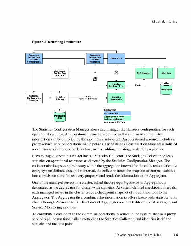
About Mon i to r ing
BEA AquaLogic Service Bus User Guide 5-5
Figure 5-1 Monitoring Architecture
The Statistics Configuration Manager stores and manages the statistics configuration for each operational resource. An operational resource is defined as the unit for which statistical information can be collected by the monitoring subsystem. An operational resource includes a proxy service, service operations, and pipelines. The Statistics Configuration Manager is notified about changes in the service definition, such as adding, updating, or deleting a pipeline.
Each managed server in a cluster hosts a Statistics Collector. The Statistics Collector collects statistics on operational resources as directed by the Statistics Configuration Manager. The collector also keeps samples history within the aggregation interval for the collected statistics. At every system-defined checkpoint interval, the collector stores the snapshot of current statistics into a persistent store for recovery purposes and sends the information to the Aggregator.
One of the managed servers in a cluster, called the Aggregating Server or Aggregator, is designated as the aggregator for cluster-wide statistics. At system-defined checkpoint intervals, each managed server in the cluster sends a checkpoint snapshot of its contributions to the Aggregator. The Aggregator then combines this information to offer cluster-wide statistics to its clients through Retriever APIs. The clients of Aggregator are the Dashboard, SLA Manager, and Service Monitoring modules.
To contribute a data point to the system, an operational resource in the system, such as a proxy service pipeline run time, calls a method on the Statistics Collector, and identifies itself, the statistic, and the data point.

Moni to r ing
5-6 BEA AquaLogic Service Bus User Guide
The Dashboard shows the overall health related information of AquaLogic Service Bus. It provides an overview of the state of the system organized by server, services, and alerts.
After monitoring is enabled, the Service Monitoring Summary page in the AquaLogic Service Bus Console provides a view of the statistics collected for each service. It also provides information about the alerts generated due to SLA violations.
As previously mentioned, an SLA is an agreement that defines the precise level of service expected from business and proxy services in AquaLogic Service Bus. The SLA Manager, with the help of the AquaLogic Service Configuration module, allows users to configure SLA rule conditions and actions. The SLA Manager monitors SLA violations with the help of data provided by the Aggregator and sends notifications as configured in the alert rule actions. The SLA Manager is always deployed with the Aggregator and resides on only one managed server in cluster. The SLA Manager gives alerts to the Alert Log to store in the Alert Store.
Monitoring ServicesWhen you create a business or proxy service, monitoring is disabled by default for that service. Enable monitoring as follows:
To enable monitoring for an individual service, select the Enable Monitoring check box on the Manage Monitoring page. Then set the aggregation interval for the service by selecting the interval times from the hour and minute drop-lists. For information on how to do this, see “Viewing the Dashboard Statistics” in Monitoring in the Using the AquaLogic Service Bus Console.
To enable monitoring for all services, select the Enable Monitoring check box on the Global Settings page. For information on how to do this, see “Enabling Monitoring” in System Administration in the Using the AquaLogic Service Bus Console.
Note: The Enable Monitoring option permits you to enable or disable monitoring of all services that have individually been enabled for monitoring. If monitoring for a particular service has not been enabled, you must first enable it and set the aggregation interval on the Manage Monitoring page before the system starts collecting statistics for that service.
When creating alert rules, you must enable monitoring before you create the rule. For more information, see “Alert Rules” on page 5-30 and “Create an Alert Rule” in Monitoring in the Using the AquaLogic Service Bus Console.

About Mon i to r ing
BEA AquaLogic Service Bus User Guide 5-7
Refresh Rate of Monitored InformationAt run time, the default refresh rate for the Dashboard page is one minute. However, it may take up to three minutes for the information to be displayed on the Dashboard. This delay happens because of the time gaps between when the messages are processed by the proxy service, when the metrics are collected, and the refresh rate of the Dashboard. The system works as follows:
1. Every minute the data collector sends the current snapshot to the aggregator.
2. Every 60 seconds, the aggregator merges all the documents it has received from the managed servers within the last minute.
3. The AquaLogic Service Bus Console refreshes every minute; that is, it runs a query on the aggregated document and then displays the results.
Figure 5-2 Aggregation Time Line
For example, a proxy service starts sending data in T1, as shown in Figure 5-2. At T2—that is, the second minute—the collector sends the data to the aggregator. However, if an aggregation cycle has just occurred, the aggregator does not merge this data until the next aggregation cycle, which occurs after one minute, or a maximum of two minutes from the previous aggregation cycle. When the data is merged, it is now available for the AquaLogic Service Bus Console. Since the console refreshes every minute, if the refresh cycle has just passed, then the data is not displayed on the console until the third minute. Therefore, three minutes is the maximum delay.
You change the Dashboard polling interval in the System Administration module in the AquaLogic Service Bus Console. For information on how to do this, see “Setting the Dashboard Polling Interval Refresh Rate” in System Administration in the Using the AquaLogic Service Bus Console.
DashboardWhen you log onto the AquaLogic Service Bus Console, the Dashboard is automatically displayed. The Dashboard shows the monitoring information for the last 30 minutes. It provides an overview of the state of the system organized by server, services, and alerts, as shown in the following figure.

Moni to r ing
5-8 BEA AquaLogic Service Bus User Guide
Figure 5-3 AquaLogic Service Bus Dashboard
As shown in the previous figure the Dashboard displays the following information:
Services Summary—if alerts have been configured, summarizes the alert status for both proxy and business services. Alerts notify you of service performance based on rules you create.
Servers Summary—displays the status of the servers.
Alerts Summary—if alerts have been configured, displays which alert rules have been triggered.
From the Dashboard, you can drill-down into the system and easily find specific information, such as the average execution time of a service, the date and time an alert occurred, or length of time a server has been running.
You configure the Dashboard and monitoring in the AquaLogic Service Bus Console, which is described in the Monitoring and System Administration sections of the Using the AquaLogic Service Bus Console.

Serv i ce Summary
BEA AquaLogic Service Bus User Guide 5-9
Service SummaryThis section contains information on the following topics:
About the Service Summary
Service Monitoring Summary
Service Monitoring Details
About the Service SummaryThe Service Summary panel provides an overview of the state of the services. The Service Summary pie chart shows the percentage of alerts according to their severity for all services that have alerts defined and monitoring enabled for the last 30 minutes. The severity level of alerts is user configurable and has no absolute meaning. Severity types include Fatal, Critical, Major, Minor, Warning, and Normal.The services having the highest severity alerts are listed beneath the pie chart, as shown in the following figure. Up to ten services can be listed in descending order of the sevice with the most alerts.
Figure 5-4 Services Summary Pane
From the Service Summary panel, you can access more information about alerts by clicking the following:
A specific area on a pie chart—displays the Service Summary page.

Moni to r ing
5-10 BEA AquaLogic Service Bus User Guide
The name of a service under Services With Highest Severity Alerts—displays the Service Monitoring Details page for that service.
View Service Summary List—displays the Service Monitoring Summary page. To help you locate specific services, you can filter the services by different criteria.
Each of these pages is fully described in the sections that follow.
Warning: When a service (or its component; for example, a pipeline node) is renamed or relocated, its statistical data is lost.
For information on how to access detailed alert information, see “Viewing the Dashboard Statistics” in Monitoring in the Using the AquaLogic Service Bus Console.
Service Monitoring SummaryThe Service Monitoring Summary page provides two views of service monitoring statistics, as shown in the following figures.
The first view is a moving statistic of the data collected by each service. This view is available when you select Current Aggregation Interval in the Show Metrics For field. The aggregation interval shown in the Aggregation Interval column determines the statistics that are displayed. For example, if the aggregation interval of a particular service is 20 minutes, that service’s row displays the data collected in the last 20 minutes.
Figure 5-5 Service Monitoring Summary Page—Current Aggregation Interval
The second view is a running count of the metrics. This view is available when you select Since Last Reset in the Show Metrics For field. The statistics displayed in each row are for the period since you last reset statistics for an individual service or since you last reset statistics for all services on the Global Settings page in the System Administration module.

Serv i ce Summary
BEA AquaLogic Service Bus User Guide 5-11
Figure 5-6 Service Monitoring Summary Page—Since Last Reset
As shown in the top section of the preceding figures, you can filter the display of information using the following criteria:
Name—the name of the proxy service or business service.
Path—the project folder in which the proxy service or business service resides.
Has Alerts—by services that have alert messages.
Has Errors—by services that have failed messages.
Invoked by proxy—the name and path of the proxy service.
The Service Monitoring Summary table displays the following information:
Name—the name of the proxy or business service. The name is a link to the Service Monitoring Details page. See “Service Monitoring Details” on page 5-12.
Path—the project folder in which the service resides. The path is a link to the Project View or Folder View page, depending on whether the service resides in the top level of a project or in a folder.
Aggregation Interval—the time period over which data points for specific statistics are collected and then displayed for the service. This information is displayed only when you have selected Current Aggregation Interval in the Show Metrics For field.
Average Execution Time—the average time it has taken the service to process a message for the period of the current aggregation interval or for the period since the last reset.
Message Count—the total number of messages processed by the service for the period of the current aggregation interval or for the period since the last reset.

Moni to r ing
5-12 BEA AquaLogic Service Bus User Guide
Error Count—the number or messages that have failed for the period of the current aggregation interval or for the period since the last reset.
Alert Counts—the number of alerts raised by alert rule occurrences and violations for the period of the current aggregation interval or for the period since the last reset.
Note: An Action column is displayed when you have selected Since Last Reset in the Show Metrics For field. In this column, you can click the Reset Statistics icon for a specific service to reset the statistics for that service. When you confirm you want to do this, the system deletes all monitoring statistics that were collected for the service since the last time you clicked the Reset Statistics icon or the last time you clicked Reset Statistics on the Global Settings page. However, the system does not delete the statistics being collected during the Current Aggregation Interval for the service. Additionally, after you click the Reset Statistics icon, the system immediately starts collecting monitoring statistics for the service again.
Service Monitoring DetailsThe Service Monitoring Details page provides you with two views of detailed information about a specific service, as shown in the following figures.
The first view is a moving statistic of the data collected by the service. This view is available when you select Current Aggregation Interval in the Show Metrics For field. The aggregation interval shown in the Aggregation Interval column determines the statistics that are displayed. For example, if the aggregation interval of this service is 20 minutes, the view displays the data collected in the last 20 minutes.

Serv i ce Summary
BEA AquaLogic Service Bus User Guide 5-13
Figure 5-7 Service Monitoring Details Page—Current Aggregation Interval
The second view is a running count of the metrics. This view is available when you select Since Last Reset in the Show Metrics For field. The statistics displayed are for the period since you last reset statistics for this particular service or since you last reset statistics for all services on the Global Settings page in the System Administration module.

Moni to r ing
5-14 BEA AquaLogic Service Bus User Guide
Figure 5-8 Service Monitoring Details Page—Since Last Reset
The displayed details have the following definitions:
Service Monitoring Details
– Alert Status—the current alert status, which is displayed only when you have selected Current Aggregation Interval in the Show Metrics For field.
– Aggregation Interval—the time period over which data points for specific statistics are collected and then displayed for the service. This information is displayed only when you have selected Current Aggregation Interval in the Show Metrics For field.
– Alerts for last Aggregation Interval—the total number of alerts associated with this service within the last aggregation interval. This information is displayed only when you have selected Current Aggregation Interval in the Show Metrics For field.
– Alerts since last reset—the total number of alerts associated with this service since you last reset statistics for the service or since you last reset statistics for all services on the Global Settings page. This information is displayed only when you have selected Since Last Reset in the Show Metrics For field.
– Alert History—a link to the Customized System Alerts History page. See “System Alerts History” on page 5-26.

Serv i ce Summary
BEA AquaLogic Service Bus User Guide 5-15
– Location Path—the project and folder where the service resides.
– Display Metrics For—displays the metrics for a server. For a single node, only one item is displayed.
Operations
– Operations—the operations associated with the service, if any exist.
– Message Count—the number of messages associated with each operation within the period of the current aggregation interval or within the period since the last reset.
– Minimum Response Time—the minimum time this operation has taken to execute messsages within the period of the current aggregation interval or within the period since the last reset.
– Maximum Response Time—the maximum time this operation has taken to execute messsages within the period of the current aggregation interval or within the period since the last reset.
– Average Execution Time—the average time the operation has taken to execute messages within the period of the current aggregation interval or within the period since the last reset.
Performance
– Minimum Response Time—the minimum time this service has taken to execute messsages within the period of the current aggregation interval or within the period since the last reset.
– Maximum Response Time—the maximum time this service has taken to execute messsages within the period of the current aggregation interval or within the period since the last reset.
– Overall Average Execution Time—the overall average time that the service has taken to execute messages within the period of the current aggregation interval or within the period since the last reset.
– Total Number of Messages—the total number of messages, including failed messages, within the period of the current aggregation interval or within the period since the last reset.
– Messages With Errors—the number of messages that failed within the period of the current aggregation interval or within the period since the last reset. In two-way messaging, if the response message fails, but the request message was processed, only the failed response message is counted.

Moni to r ing
5-16 BEA AquaLogic Service Bus User Guide
– Failover Count—for business services only, the number of failover messages within the period of the current aggregation interval or within the period since the last reset.
– Success Ratio—the percentage of successfully processed messages within the period of the current aggregation interval or within the period since the last reset.
– Failure Ratio—the percentage of messages that failed to process within the period of the current aggregation interval or within the period since the last reset.
– Security—the number of messages that failed due to security reasons, such as authentication errors, security policy violations, or authorization errors, within the period of the current aggregation interval or within the period since the last reset.
– Validation—the number of messages that failed when a validate action compared one or more parts of a message against an XSD schema or WSDL resource, within the period of the current aggregation interval or within the period since the last reset. Displays for proxy services only.
Flow Components for proxy services
– Component Name—the name of pipeline or node in the message flow.
– Message Count—the number of messages associated with each component within the period of the current aggregation interval or within the period since the last reset.
– Error Count—the number of failed messages associated with each component within the period of the current aggregation interval or within the period since the last reset.
– Average Execution Time—the average time the component has taken to execute a message within the period of the current aggregation interval or within the period since the last reset.
Server SummaryThis section contains information on the following topics:
About the Server Summary
Log Summary
Server Summary
Server Details

Se rve r Summary
BEA AquaLogic Service Bus User Guide 5-17
About the Server SummaryThe Server Summary panel provides an overview of the state of the servers. The pie chart shows the status of each server in the domain. The status for each server is derived from the WebLogic Diagnostic Service (see Configuring and Using the WebLogic Diagnostics Framework.). The ten most critical servers are displayed, as shown in Figure 5-9.
Figure 5-9 Server Summary Pane
The displayed statuses have the following meanings:
Fatal—the server has failed and must be restarted.
Critical—server failure pending; something must be done immediately to prevent failure. For more details, check the server logs and the corresponding RuntimeMBean.
Warning—the server could have problems in the future. For more details, check the server logs and the corresponding RuntimeMBean.
Ok—the server is functioning without any problems.
Overloaded—the server has more work assigned to it than the configured threshold; it might refuse more work.
Log SummaryThe AquaLogic Service Bus Console allows you to view the WebLogic Server domain log. The domain log file provides a central location from which to view the overall status of the domain. Each server instance forwards a subset of its messages to a domain-wide log file. By default, servers forward only messages of severity level NOTICE or higher. You can modify the set of

Moni to r ing
5-18 BEA AquaLogic Service Bus User Guide
messages that are forwarded. For more information, see Understanding WebLogic Logging Services in Configuring Log Files and Filtering Log Messages.
If you configure the logging action in a pipeline, the log is forwarded to the server log. Unless you configure WebLogic Server to forward these messages to the domain log, you cannot view this log from AquaLogic Service Bus Console. For information in how to do this, see Create Log Filters in the WebLogic Server Administration Console Online Help.
To see the number of messages currently raised by the system, click the View Log Summary link in the Server Summary panel. A table is displayed that contains the number of messages grouped by severity, as shown in the following figure.
Figure 5-10 Log Summary
The displayed message statuses have the following meanings:
Alert—a particular service is in an unusable state while other parts of the system continue to function. Automatic recovery is not possible; the immediate attention of the administrator is needed to resolve the problem.
Critical—a system or service error has occurred. The system can recover but there might be a momentary loss or permanent degradation of service.

Se rve r Summary
BEA AquaLogic Service Bus User Guide 5-19
Emergency—the server is in an unusable state. This severity indicates a severe system failure.
Error—a user error has occurred. The system or application can handle the error with no interruption. Limited degradation of service may occur.
Info—reports normal operations; a low-level informational message.
Notice—an informational message with a higher level of importance than Info messages.
Warning—a suspicious operation or configuration has occurred. However, normal operations may not be affected.
This display is based on the health state of the running servers, as defined by the WebLogic Diagnostic Service. For more information about the WebLogic Diagnostic Service, see Configuring and Using the WebLogic Diagnostics Framework.
To view the domain log for a particular type of message, click the number corresponding with the type of message. The following figure shows an example of a domain log file displayed in the AquaLogic Service Bus Console.
Figure 5-11 Domain Log File Entries
The following information is displayed:
– Date—the date and time the entry was logged in a format that is specific to the local time zone and format.

Moni to r ing
5-20 BEA AquaLogic Service Bus User Guide
– Subsystem—the WebLogic Server subsystem that was the source of the message, such as the EJB container or Java Messaging Service.
– Severity—indicates the degree of impact or seriousness of the event.
– Message ID—the unique six-digit identification for the message.
– Message—a description of the event or condition.
For more information, see “Message Attributes” in Understanding WebLogic Logging Services in Configuring Log Files and Filtering Log Messages.
To display details of a single log file on the page, select the radio button for the appropriate log, then click the View button.
Server SummaryThe Server Summary page provides a customizable table of servers, as shown in the following figure.
Figure 5-12 Server Summary Page
As shown in the top section of the preceding figure, the Server Summary Page displays the number of messages currently raised by the system. For information about the meaning of each type of status message, see “Log Summary” on page 5-17.
The server table displays the following information:
Status—the status of the server:

Se rve r Summary
BEA AquaLogic Service Bus User Guide 5-21
– Fatal—the server has failed and must be restarted.
– Critical—server failure pending; something must be done immediately to prevent failure. For more details, check the server logs and the corresponding RuntimeMBean.
– Warning—the server could have problems in the future. For more details, check the server logs and the corresponding RuntimeMBean.
– OK—the server is functioning without any problems.
– Overloaded—the server has more work assigned to it than its configured threshold; it might refuse more work.
Server—the name of the server. The name is a link to the View Server Details page. See “Server Details” on page 5-22.
Cluster Name—if the server is associated with a cluster, the name of the cluster.
Machine Name—the name of the computer associated with the server.
State—the state of the server:
– RUNNING
– FAILED
– SHUTDOWN
Uptime—the length of time this server has been running.
To view this information in the table as a pie or bar chart, click View as a Graph.
To filter the display of servers, click Customize Table above the server table. The available filtering is shown in the following figure.

Moni to r ing
5-22 BEA AquaLogic Service Bus User Guide
Figure 5-13 Server Summary Table Filter
For information about how to use the Server Summary Table Filter, see “Customize Your View of the Server Summary” in Monitoring in the Using the AquaLogic Service Bus Console.
Server DetailsYou can access the View Server Details page by clicking the name of a server under Most Critical Servers or by clicking the name of a server in the Servers Summary page.
The View Server Details page enables you to view more server monitoring details, as shown in the following figure.

Se rve r Summary
BEA AquaLogic Service Bus User Guide 5-23
Figure 5-14 Server Details Page—General Tab
The information displayed on this page is a subset of the Monitoring tab in the AquaLogic Service Bus Console Server Settings page. The details available are:
General—provides general run-time information about the server. Click Advanced to display more information, such as WebLogic Server version or operating system name.
Channels—displays monitoring information about each channel.
Performance—displays performance information about the server.
Threads—displays current run-time characteristics and statistics for the server’s active executable queues.
Timers—displays information about the timer in use by the server.
Workload—displays statistics for work managers, constraints, and policies configured for the server.
Security—allows you to monitor user-lockout management statistics for the server.
JMS—allows you to monitor JMS information about the server.

Moni to r ing
5-24 BEA AquaLogic Service Bus User Guide
JTA—displays the summary of all transaction information for all resource types on the server.
For more information, see the WebLogic Server Administration Console Online Help.
Alert SummaryThis section contains information on the following topics:
About the Alert Summary
System Alerts History
System Alert Details
View Alert Rule Details
About the Alert SummaryThe Alert Summary panel contains a customizable table displaying information about violations or occurrences of events in the system. These violations and occurrences are based on SLAs. AquaLogic Service Bus provides various SLA monitors that you can configure to monitor proxy and business services. Some examples of SLA monitors are maximum execution time and authorization failure. You configure these monitors by creating alert rules. When a rule evaluates to true, it raises an alert. Additionally, you configure an alert rule to send an email or post a message on a JMS queue or topic.
Note: When you configure an alert rule to post a message to a JMS destination, you must create a JMS connection factory and a queue or topic, and target them to the appropriate JMS server in the WebLogic Server Administration Console. For information on how to do this, see “Configuring a JMS Connection Factory” and “JMS Resource Naming Rules for Domain Interoperability” in Configuring JMS System Resources in Configuring and Managing WebLogic JMS.
The AquaLogic Service Bus Console provides several ways to view and find alerts, such as by severity and by service. You can also view alerts graphically. For information on how to do this, see “Listing and Locating Alerts” and “Viewing a Chart of Alerts” in Monitoring in the Using the AquaLogic Service Bus Console.
The following figure shows the Alert Summary panel:

Al er t Summary
BEA AquaLogic Service Bus User Guide 5-25
Figure 5-15 Alert Summary Panel
The Alert Summary panel shows alerts for the last 30 minutes. It contains the following types of information:
Alert Severity—the user-defined severity of the alert. The Severity is a link to the Alert Details page. See “System Alert Details” on page 5-28.
Timestamp—the date and time that the alert occurred.
Alert Rule Name—the name assigned to the alert. The name is a link to the View Alert Rule Details page. See “View Alert Rule Details” on page 5-29.
Service/Project Name—the name of the service and project associated with the alert. The name is a link to the Service Monitoring Details page. See “Service Monitoring Details” on page 5-12.
To view a complete list of alerts, click View Alert Summary List. See “System Alerts History” on page 5-26.
To customize the information displayed in the Alert Summary Panel, click Customize table above the summary table. The available filtering is shown in the following figure.
Figure 5-16 Alert Summary Table Filter

Moni to r ing
5-26 BEA AquaLogic Service Bus User Guide
System Alerts HistoryTo access the Customized System Alerts History page, in the Alert Summary panel, click View Alert Summary List. The Customized System Alerts History page enables you to view all the alerts by paging through the table (Figure 5-17) or by filtering the display of the alerts (Figure 5-18).
Figure 5-17 Customized System Alerts History
The table shown in the preceding figure is customizable and provides the following information:
Alert Severity—the severity level of alerts is user configurable and has no absolute meaning. The field is a link to the System Alert Details page. See “System Alert Details” on page 5-28.
Timestamp—the date and time that the alert occurred.
Alert Rule Name—the name assigned to the alert. The name is a link to the View Alert Rule Details page. See “View Alert Rule Details” on page 5-29.
Service/Project Name—the name of the service and project associated with the alert. The name is a link to the Service Monitoring Details page. See “Service Monitoring Details” on page 5-12.
To view a pie or bar chart of the alerts, click View Graph in the table.

Al er t Summary
BEA AquaLogic Service Bus User Guide 5-27
To search for a specific alert, you can filter the display of alerts by clicking Customize Table in the Customized System Alerts History table. The available filtering is shown in the following figure.
Figure 5-18 System Alerts Table Filter
For information about how to use the Alerts Table Filter, see “Customizing Your View of Alerts” in Monitoring in the Using the AquaLogic Service Bus Console.
Note: When an alert is fired in your configuration, a message is sent to your domain log, which resides at the following location:
[BEA_home\servers\<server_name>\logs\<domain_name>.log
Where domain_name represents the name you assigned your AquaLogic Service Bus domain when you created it.
The message is logged as an alert and has this message ID: BEA-394015
The message body is a string that consists of the following elements:
Alert Rule ID
Alert Rule Name
Severity

Moni to r ing
5-28 BEA AquaLogic Service Bus User Guide
Timestamp
Name of the service associated with the alert
System Alert DetailsThe System Alert Details page displays complete information about the alert and allows you to add an annotation to the alert, as shown in the following figure.
Figure 5-19 Rule Details Page
The following information is displayed:
Alert Name—the name assigned to the alert.
Description—a description of the alert.
Timestamp—the date and time the alert occurred.
Severity—the user-defined severity of the alert.
Alert Rule Name—the name of the alert rule. The name is a link to the View Alert Rule Details page. See “View Alert Rule Details” on page 5-29.
Service—the name of the service associated with the alert. The name is a link to the Service Monitoring Details page. See “Service Monitoring Details” on page 5-12.
Annotation—use this field to add notes to the alert.
You access this page from the Dashboard by clicking Alert Severity in the Alert Summary table. This page also allows you to delete the alert.

Al er t Summary
BEA AquaLogic Service Bus User Guide 5-29
View Alert Rule DetailsThe View Alert Rule Details page displays complete information about a specific alert rule, as shown in the following figure.
Figure 5-20 View Alert Rule Details Page
The following information is displayed:
General Configuration
– Rule Name—the name assigned to the alert rule.
– Description—a description of the rule.
– Start Time (HH:MM)—specifies the starting time during which the rule is active on each day prior to the expiration date.
– End Time (HH:MM)—specifies the ending time during which the rule is active on each day prior to the expiration date.
– Rule Expiration Date (MM/DD/YY)—the expiration date of the rule. The rule expires at 12.01am on the specified date. If you do not specify a date, the rule never expires.
– Rule Enabled—indicates whether the rule is enabled or not.
– Alert Severity—the user-defined severity of the alert.

Moni to r ing
5-30 BEA AquaLogic Service Bus User Guide
– Alert Frequency—indicates whether the actions (email or JMS destination) designated in the alert rule are executed every time the alert rule evaluates to true or are executed the first time the rule evaluates to true.
– Stop Processing More Rules—when multiple rules associated with a service exist, this flag indicates whether subsequent rules associated with the service must be evaluated if the current rule evaluates to true.
– Include Log in Management Data Set—indicates whether a log of the alert is included in the management data set. These alert logs are visible on the Dashboard in the Alert Summary table.
– Include Log in Reporting Data Set—indicates whether a log of the alert is included in the reporting data set. Viewing the reporting data set requires developing a Reporting Provider to fetch and display these logs. For more information, see “Reporting Framework” on page 6-3.
Conditions
– Condition Expression—displays the condition that triggers the alert rule.
Action Parameters
– Send an alert via e-mail
– Send an alert to a JMS Destination
For information about how to define alert rules, see “Create an Alert Rule” in Monitoring in the Using the AquaLogic Service Bus Console.
Alert RulesThis section includes information on the following topics:
About Alert Rules
Some Uses for Alerts
Understanding Alert Rules
About Alert RulesAs mentioned earlier, alerts are automated responses to SLAs violations or occurrences, which are displayed on the Dashboard. You define alert rules to specify unacceptable service performance according to your business and performance requirements. Each alert rule allows

Ale r t Ru les
BEA AquaLogic Service Bus User Guide 5-31
you to specify the aggregation interval for that rule when configuring the alert rule. The alert aggregation interval is not affected by the aggregation interval set for the service.
Rules are executed once every aggregation interval. On the Alert Rule page, if you set the Alert Frequency to Every Time, the rule’s actions are executed every time the alert rule evaluates to true. If you set the Alert Frequency to Once Until Conditions Clear, the rule’s actions are executed the first time the rule evaluates to true, and no more alerts are generated until the condition resets itself and evaluates to true again.
In the case where the Alert Frequency is set to Every Time, the number of times an alert rule is fired depends on the aggregation interval and the sample interval associated with that rule. For example, if the aggregation interval is set to 5 minutes, the sample interval is 1 minute. Rules are evaluated each time 5 samples of data are available. Therefore, the rule is evaluated for the first time approximately 5 minutes after it is created and every minute thereafter.
In the case where the Alert Frequency is set to Once Until Conditions Clear, after an alert is fired the first time in an aggregation interval, it is not fired again in the same aggregation interval.
Creating an alert rule involves three parts:
General Configuration—defines the name, duration, severity, frequency, logging, and other general behavior.
Define Conditions—defines one or more conditions that trigger the alert rule. Additionally, you defined the aggregation interval for the condition on this page.
Define Actions—defines whether to use an email or JMS message for notification that the rule was triggered.
Note: Rules can only be created for services that are enabled for monitoring.
Detailed information about creating an alert rule is located in “Create an Alert Rule” in Monitoring in the Using the AquaLogic Service Bus Console.
Some Uses for AlertsThe following are some uses for alerts:
Monitoring and email notification of WS-Security errors.
Monitoring the number of messages passing through a particular pipeline.
Email notification when the average execution time exceeds 5 seconds during stock exchange hours.

Moni to r ing
5-32 BEA AquaLogic Service Bus User Guide
Understanding Alert RulesThe information in this section is presented in question-answer format.
Question 1: I created a service with an alert rule that has the following condition expression:
Aggregation Interval: 0 Hours(s) and 1 MinutesMessage Count = 0
It’s been 10 minutes and I have not received any alerts.
Answer: Monitoring statistic collection for each statistical attribute, such as message count and error count, associated with a service begins when a change in the value of that statistic occurs. Data collection for the Message Count attributes begins when the first message is processed by the service and the Message Count attribute is incremented. Similarly, collection of data for the Error Count statistic starts only when the service encounters its first error and the Error Count attribute is incremented. If the service is idle, no monitoring information is collected for that service and subsequently no alert rules are triggered. After the first message is processed, monitoring data for that service is continually collected even if the service does not receive any further requests. Check to see if the service has received any requests.
Question 2: I defined a new alert rule with an aggregation interval that did not exist before and that rule does not seem to fire at all. All other rules created prior to this one are working correctly.
Answer: The cause is the same as in Question 1; the service needs to process at least one request after a rule with a new aggregation interval is created to trigger the alert rule. The other rules defined with different aggregation interval values are not affected by the alert rule.
Question 3: I restarted the server and none of my services have processed any requests. Why do I see alerts being generated?
Answer: Once the Monitoring subsystem has started collecting data for services, killing and restarting a server does not abort the collection process. The data collected is persisted and statistic collection picks up from where it left off.
Question 4: I have an alert rule with the following definition:
Aggregation Interval: 0 Hours(s) and 5 MinutesSuccess Rate < 80%
The Service Monitoring Summary page shows the following values:
Message Count: 4
Error Count: 1
Why am I being alerted in this case? Shouldn’t the success rate be 80% in this case?

Ale r t Ru les
BEA AquaLogic Service Bus User Guide 5-33
Answer: No, the message count value displayed is the total of all messages processed by the service, including the ones that generated an error. Subsequently, in this case, the success rate is 75%.
Question 5: I created a service with an aggregation interval of 10 minutes that sends a JMS message. I could see the message on the Service Monitoring Summary page, but some time later the message count for my service shows as zero.
Answer: The Service Monitoring Summary page displays a moving statistic. In this case, it shows the message count in the last 10 minutes. Because no messages were processed by the system in the last 10 minutes, the message count is displayed as zero.
Question 6: I changed the aggregation interval of a service from 10 minutes to 5 minutes. The Service Monitoring Summary page shows all statistics as zero. One of the alerts in this server was configured to a statistical element with a 2 minute aggregation interval, which did not fire the next minute.
Answer: Changing the aggregation interval for a service removes the statistical information for all the services and alerts associated with that service. The alert initializes again and fires after the next aggregation interval expiry.
Question 7: I have a business service with multiple endpoints with an alert rule defined as Failover-count > 0. When one of the endpoints goes down, the alert is triggered. However, when a service has only one endpoint, the Failover-count is not incremented for this service. Instead, an error is generated.
Answer: Set the Retry count to a number greater than zero. For information about setting the Retry count, see “Adding a Business Service” in Business Services in the Using the AquaLogic Service Bus Console.
Question 8: I see that an alert is generated on the Dashboard but the value for the Alerts for last Aggregation Interval field on the Service Monitoring Details page displays zero.
Answer: Alert rules are evaluated after the completion of the interval, which happens after a checkpoint completion. If a rule evaluates to true, the rule’s actions are triggered, a log is generated, and the interval-count statistic attribute (Alerts for Last Aggregation Interval) is incremented. The updated value of this counter is processed in the next checkpoint, 60 seconds later. The Monitoring Details page displays the updated count approximately one minute after the alert is generated.
Question 9: How does the active time for rules that span midnight work?
Answer: Consider the case where the active time for a rule is specified as 22:00 to 09:00.

Moni to r ing
5-34 BEA AquaLogic Service Bus User Guide
On a given date, say June 7, the rule will be active and inactive as follows:
June 6, 10:00 P.M. to June 7, 9:00 A.M. – Active
June 7, 9:01 A.M. to June 7, 9:59 P.M. – Inactive
June 7, 10:00 P.M. to June 8, 9:00 A.M. – Active
The Collector sends ServerStatistics to the aggregator. The ServerStatistics represents the monitoring runtime data for that minute. In other words, it contains the statistics information for the services that have been enabled.
Every minute the aggregator aggregates the data received from the collector, and makes it available for the retriever sub system. The aggregator thread is skewed by 15 sec wrt to the collector checkpoint thread.
If you disable monitoring for the domain, you disable the statistics collection and the checkpointing process. The Collector no longer sends ServerStatistics to the aggregator server and the aggregator server does not have any aggregated data from the next minute, which means there is no data returned if you attempt to retrieve it. The same applies when you enable monitoring for the domain. The system initially does not show any data. However, after a maximum of two minutes, the aggregator has data and the Service Summary page displays this data.
As documented, disabling monitoring for the domain disables the statistics collection and the checkpointing process; that is, it no longer sends serverStatistics to the aggregation server and the aggregator server does not have any aggregated data from the next minute, which means when the user tries to retrieve the data it returns no configurations.
The same applies when one enables the domain monitoring , the system initially does not show any data and after a maximum of two minutes the aggregator would have data and service summary displays the same.

BEA WebLogic Service Bus User Guide 6-1
C H A P T E R 6
Reporting
BEA AquaLogic Service Bus provides the capability to deliver message data and alerts to one or more reporting providers. Message data can be captured not only from the body of the message but any other variables associated with the message, such as header or inbound variables. Alert data contains information about Service Level Agreement (SLA) violations or occurrences that you can configure to monitor proxy services. You can use the message or alert data delivered to the reporting provider for functions such as tracking messages or regulatory auditing.
AquaLogic Service Bus includes a JMS Reporting Provider for message reporting. The Reporting module in the AquaLogic Service Bus Console displays the information captured from this reporting provider. If you do not wish to use the out-of-the-box reporting provider, you can untarget it and create your own reporting provider using the Reporting Service Provider Interface (SPI). If you configure your own reporting provider for messages, no information is displayed in the AquaLogic Service Bus Console and you will need to create your own user interface. If you wish to capture SLA data, you will need to create a reporting provider for alerts.
This chapter contains information on the following topics
Reporting Scenarios
Reporting Framework
JMS Reporting Provider
How to Enable Message Reporting
Removing, Stopping, or Untargeting a Reporting Provider

Repo r t i ng
6-2 BEA WebLogic Service Bus User Guide
Reporting ScenariosThe following scenarios describe some of the ways in which you can use AquaLogic Service Bus to track messages:
Message TrackingIn “Alert Monitoring” on page 5-2, a scenario was described where the number of alerts had increased significantly. In that scenario, you filtered the alerts and discovered that the Service Level Agreement (SLA) violations were due to errors produced by the Post-Trade Processing proxy service. Reporting helps you find the source of the errors more easily.
To continue the scenario, you proceed to the AquaLogic Service Bus Console, where you filter messages to display the Post-Trade Processing proxy service. Drilling into some of the messages, you discover that the pipeline errors are due to message transformation errors and that the mangled messages are coming out of the portal associated with the proxy service. To solve the problem, a developer adds a new transformation to the pipeline for all messages originating from that portal site.
Search for a Particular MessageCustomer Service calls Operations with a complaint that the customer who submitted trade 1234 did not receive a trade confirmation. You access the AquaLogic Service Bus Console and search for the trade number. The search shows that two messages were processed in the request pipelines, but no response messages. You ask Customer Service to contact the customer and assure the customer that the trade was successfully processed.
Logging for Regulatory AuditingAt the end of the month, the Mortgage Processing team must provide their compliance department with information about the mortgages they have processed. To fulfill this requirement, the Application Development team updates the applicable proxy service pipelines to capture the relevant message information. Specifically, data is extracted from the messages for the customer ID and name, mortgage ID, mortgage amount, property address, and the date the loan application was submitted.
Alert Reporting ProviderBy configuring a reporting provider for alerts you can receive an alert notification outside of the AquaLogic Service Bus Console and process the alert according to your business needs. For example, you could develop an alert reporting provider that utilizes the reporting stream for alerts and then display the alerts on a custom console, such as HP OpenView, or Tivoli.

Repo r t ing F ramework
BEA WebLogic Service Bus User Guide 6-3
Reporting FrameworkAquaLogic Service Bus contains an extensible framework for creating one or more reporting providers for messages or alerts.
To enable message reporting you must first create a Report action in the message flow for the proxy service. The Report action allows you to extract information from each message and write it to the AquaLogic Service Bus Reporting Data Stream. You do not need to configure a report action for alert reporting. Alert data is always available in the Reporting Data Stream. For more information, see “How to Enable Message Reporting” on page 6-6.
All the information you need to create your own reporting provider is located in com.bea.wli.reporting within the Javadoc for AquaLogic Service Bus. The Javadoc provides information about what you need to do to implement a reporting provider, including how to package it, where it goes, how to deploy it, and the order of deployment. The location of the reporting schema (MessageReporting.xsd) is BEA_HOME/weblogic90/servicebus/lib/sb-schemas.jar, where BEA_HOME is the location where you installed your BEA products.
The following figure shows the reporting framework.
Figure 6-1 Reporting Framework
As shown in the previous figure, both report messages and alerts are exported to reporting data streams. In the Report stage, information is extracted by the Report action from each message and written to the Reporting Data Stream with metadata that adheres to MessageReporting.xsd. Similarly, the SLA Manager uses Reporting Data Manager APIs to write to the Alert Reporting Stream with metadata that adheres to the AlertReporting.xsd. If you want to develop a

Repo r t i ng
6-4 BEA WebLogic Service Bus User Guide
reporting provider for alerts or your own message reporting provider, you need to implement one interface called ReportingDataHandler and use one class called ReportingDataManager.
The ReportingDataHandler Interface takes the reporting or alert data stream and processes it. It can process and/or store this stream in a relational database, file, JMS queue, and so on. Depending on which stream you want to use, you need to implement the appropriate handle methods to process the data stream:
Message Reporting Stream—the report action of AquaLogic Service Bus run time uses the following two handle methods to write to the Message Reporting Stream:
handle(com.bea.xml.XmlObject metadata, String s)
handle(com.bea.xml.XmlObject metadata, com.bea.xml.XmlObject data)
Alert Reporting Stream—the Alert Manager uses the following handle method to write to the Alert Reporting Stream:
handle(com.bea.xml.XmlObject metadata, com.bea.xml.XmlObject data)
The ReportingDataManager is a server-local singleton object that keeps a registry of reporting providers. Reporting providers implement the ReportingDataHandler interface. The ReportingDataManager provides operations that add and remove reporting data handlers and exports reporting data stream using various handle operations.
JMS Reporting ProviderThe out-of-the-box JMS Reporting Provider provides a pluggable architecture to capture the reporting information from each message via a Report action. All messages across the cluster are aggregated and stored in the JMS Reporting Provider Data Store in a database specific format. When you use the out-of-the-box JMS Reporting Provider, the Reporting module in the AquaLogic Service Bus Console displays information from the JMS Reporting Provider Data Store.
Note: The JMS Reporting Provider is automatically configured when you create an AquaLogic Service Bus domain. If you do not wish to use this reporting provider, you must untarget it. For more information, see “Removing, Stopping, or Untargeting a Reporting Provider” on page 6-14.
This section contains information on the following topics:
About the JMS Reporting Provider
Using the Reporting Module

JMS Repor t ing Pr ov ide r
BEA WebLogic Service Bus User Guide 6-5
About the JMS Reporting ProviderThe JMS Reporting Provider consists of a producer and a consumer, which are decoupled to improve scalability. The producer is a JMS producer and the MDB (Message Driven Bean) acts as the JMS consumer, as shown in the following diagram.
Figure 6-2 JMS Reporting Provider
The Reporting stage contains the Report actions that collect the reporting information and dispatch the reporting stream to JMS Reporting Provider through various handle operations in the ReportingDataManager. The JMSReportingDataHandler is the JMS producer of the reporting provider. The JMSReportingDataHandler takes the reporting stream and logs the information to a JMS queue. The MDB listens to the JMS reporting queue, which processes the message asynchronously and stores the data in the JMS Reporting Provider Data Store.

Repo r t i ng
6-6 BEA WebLogic Service Bus User Guide
How to Enable Message ReportingTo receive report messages from either the out-of-the-box JMS Reporting Provider or your reporting provider you must first create a Report action in the message flow for the proxy service. The Report action allows you to extract information from each message and write it to the AquaLogic Service Bus Reporting Data Stream. In the Report action, you specify the information you want to extract from the message and add to the AquaLogic Service Bus Reporting Data Stream.
You do not need to configure a report action for alert reporting. Alert data is always available in the Reporting Data Stream.
When configuring a Report action, you use key values to extract key identifiers from the message. You can configure multiple keys. Information can be captured not only from the body of the message but any other variable associated with the message, such as header or inbound variables. For more information about message variables, see Message Context in the Using the AquaLogic Service Bus Console.
You can use any XML elements as a key:
<?xml version="1.0" encoding="utf-8"?>
<poIncoming><areacode>408</areacode><item-quantity>100</item-quantity><item-code>ABC</item-code><item-description>Medicine</item-description>
</poIncoming>
For example, you can specify the key as the itemcode, the value as .//item-code (an xpath expression), and the variable as message body (body), as shown in the following figure.
Figure 6-3 Key Name and Value
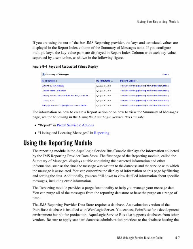
Us ing the Repor t ing Modu le
BEA WebLogic Service Bus User Guide 6-7
If you are using the out-of-the-box JMS Reporting provider, the keys and associated values are displayed in the Report Index column of the Summary of Messages table. If you configure multiple keys, the key-value pairs are displayed in Report Index Column with each key-value separated by a semicolon, as shown in the following figure.
Figure 6-4 Keys and Associated Values Display
For information on how to create a Report action or on how to view the Summary of Messages page, see the following in the Using the AquaLogic Service Bus Console:
“Report” in Proxy Services: Actions
“Listing and Locating Messages” in Reporting
Using the Reporting ModuleThe reporting module in the AquaLogic Service Bus Console displays the information collected by the JMS Reporting Provider Data Store. The first page of the Reporting module, called the Summary of Messages, displays a table containing the extracted information and other information, such as the time the message was written to the database and the service with which the message is associated. You can customize the display of information on this page by filtering and sorting the data. Additionally, you can drill down to view detailed information about specific messages, including error information.
The Reporting module provides a purge functionality to help you manage your message data. You can purge all of the messages from the reporting datastore or base the purge on a range of time.
The JMS Reporting Provider Data Store requires a database. An evaluation version of the PointBase database is installed with WebLogic Server. You can use PointBase for a development environment but not for production. AquaLogic Service Bus also supports databases from other vendors. Be sure to apply standard database administration practices to the database hosting the

Repo r t i ng
6-8 BEA WebLogic Service Bus User Guide
JMS Reporting Provider Data Store. For more information, see “Configuring a Database for the JMS Reporting Provider Store” on page 6-13.
All information about how to use the reporting module is located in the Using the AquaLogic Service Bus Console.
This section includes information on the following topics:
Summary of Messages
View Message Details
Purging Messages
Summary of MessagesWhen you click Reporting in the navigation panel, the Summary of Messages page is displayed. This page contains a table that provides a list of report messages sorted by the time the message was written in the database.
Figure 6-5 Summary of Messages
If the messages are not filtered, the Summary of Messages table displays up to 100 of the latest messages based on the database timestamp. If you filter the messages, up to 1000 messages are displayed.
Note: After you filter the message, the filter remains in effect until you update it.
The table shown in the preceding figure provides the following information:
Report Index—displays the key-value pairs extracted from the message context variables or the message payload. For more information, see “About the JMS Reporting Provider” on page 6-5.
DB TimeStamp—the timestamp of the database when the message was registered.
Inbound Service—the inbound service associated with the message. The service is a link to the View Proxy Service Details page.

Us ing the Repor t ing Modu le
BEA WebLogic Service Bus User Guide 6-9
Error Code—the error code associated with this message if it exists. For more information about error codes, see “Error Messages and Handling” in Proxy Services: Error Handlers in the Using the AquaLogic Service Bus Console.
To search for specific messages, you can filter the display of messages by clicking Filter in the Summary of Messages Table. The available filtering is shown in the following figure.
Figure 6-6 Summary of Messages Search
As shown in the previous figure, you can filter report messages for a specified period of time, by the name of a service, by error code, and by report index. After you filter the messages, the title of the page changes to Summary of Filtered Messages. For information on how to use the Summary of Messages filter, see “Listing and Locating Messages” in Reporting in the Using the AquaLogic Service Bus Console.
To view more information about a report message, click the name of the message in the Report Index column. The View Message Details page is displayed.
View Message DetailsThe View Message Details page displays complete information about the report messages, as shown in the following figure.

Repo r t i ng
6-10 BEA WebLogic Service Bus User Guide
Figure 6-7 Report Message Detail Page
The page shows the following information:
General Configuration
– Message ID—the unique identification for this message.
– Database Timestamp—the timestamp of the database when the message was registered.
– Time at point of Logging—the date and time, on the server machine, that the message was reported.
– Server name—the name of the server from which this message was generated.

Us ing the Repor t ing Modu le
BEA WebLogic Service Bus User Guide 6-11
– State—state of the pipeline from which this message was generated, as follows:
REQUEST—indicates that the reporting action was executed in a request pipeline.
RESPONSE—indicates that the reporting action was executed in a response pipeline.
ERROR—the action was running in the service-level error handler.
– Node Name—the pipeline node from which this message was generated.
– Pipeline Name—the pipeline from which this message was generated.
– Stage Name—the stage from which this message was generated.
Inbound Service
– Name—the inbound proxy service associated with this message. An inbound proxy service exchanges messages with client applications. The name is a link to the View Proxy Service Details page. For more information about this page, see “Viewing and Changing Proxy Services” in Proxy Services in the Using the AquaLogic Service Bus Console.
– URI—the URI associated with the proxy service.
– Operation—the inbound operation associated with this message. Operations are the tasks performed by a pipeline or route node in the message flow associated with the service.
Outbound Service
– Name—the outbound business service associated with this message. An outbound business service exchanges messages with an AquaLogic Service Bus proxy service. The name is a link to the View Business Service Details page. For more information about this page, see “Viewing and Changing Business Services” in Business Services in the Using the AquaLogic Service Bus Console.
– URI—the URI to the outbound business service end point.
– Operation—name of the operation invoked on the outbound service. Operations are the tasks performed by a pipeline or route node in the message flow associated with the service.
Report Index
– Report Text Index—displays the key-value pairs extracted by a Report Action from the message context variables or the message payload. For more information, see “About the JMS Reporting Provider” on page 6-5.

Repo r t i ng
6-12 BEA WebLogic Service Bus User Guide
Fault
– Error Code—the code associated with the message, if it exists. For more information, see “Error Messages and Handling” in Proxy Services: Error Handlers in the Using the AquaLogic Service Bus Console.
– Reason—the reason for the error code.
– Detail—The fault details associated with the error code. These details, if present, are typically a stack trace of where a particular fault occurred, which may be truncated due to a size limitation in the database. The limit is 2048 characters.
Report Body
– Detail—opens a browser window that displays the report body. You use an XQuery expression in a Report Action to capture the report body text. For more information, see “Report” in Proxy Services: Actions and “Using the Inline XQuery Expression Editor” in Proxy Services: XQuery Editors in the Using the AquaLogic Service Bus Console.
Purging MessagesYou can purge all of the messages from the reporting datastore or base the purge on a range of time. Message purging is an asynchronous process that occurs in the background of the AquaLogic Service Bus Console. This feature prevents the Summary of Messages page in the AquaLogic Service Bus Console from being locked up while the purge occurs.
Figure 6-8 Purging Messages Page
The length of time it takes a purge to complete depends on how many messages are in the purge. The deletion of messages is slowed if you search for reporting messages during the purge process. Additionally, the Summary of Messages page may display incorrect data as some data may not yet be purged.

Us ing the Repor t ing Modu le
BEA WebLogic Service Bus User Guide 6-13
Because the purge process is asynchronous and occurs in the background, the AquaLogic Service Bus Console does not display any messages to indicate that a purge is in process. However, if another user attempts to start a purge when a purge is already taking place, the following message is displayed:
A Purge job is already running. Please try later.
Configuring a Database for the JMS Reporting Provider StoreAquaLogic Service Bus requires a database for the JMS Reporting Provider Data Store. The PointBase database that is installed with WebLogic Server is for evaluation purposes only and not intended for a production environment. Non-evaluation development or other use of the PointBase Server requires that you obtain a separate PointBase license directly from DataMirror.
In a production environment you must use one of the supported databases. For the latest information about supported databases, see “Supported Databases and Drivers” in Supported Configurations for WebLogic Platform in Supported Configurations for AquaLogic Service Bus.
This section contains information on the following topics:
Configuring a Database in a Development Environment
Configuring a Database for Production
Configuring a Database in a Development EnvironmentWhen you create an AquaLogic Service Bus domain, the Configuration Wizard does not create database tables automatically. In a development environment, the out-of-the-box JMS Reporting Provider checks whether the tables exist for the specified database at run time. If the tables do not exist, the Reporting Provider creates them; if they do exist, the Reporting Provider uses them.
Note: If you are using Pointbase, you do not need to specify a database in the Configuration Wizard.
You can specify which database is used by the JMS Reporting Provider in one of the following ways:
Run the reporting SQL scripts in your AquaLogic Service Bus domain. The scripts are located in BEA_HOME/weblogic90/integration/common/dbscripts, where BEA_HOME represents the location in which you installed your WebLogic products.
When you create your domain in the Configuration Wizard, customize the JDBC Settings on the Run Database Scripts page (see Figure 6-9). For more information, see Creating WebLogic Domains Using the Configuration Wizard.

Repo r t i ng
6-14 BEA WebLogic Service Bus User Guide
Figure 6-9 Run Database Scripts in the Configuration Wizard
Configuring a Database for ProductionComplete information about configuring a database for production is located in the BEA AquaLogic Service Bus Deployment Guide in the following chapters:
Configuring a Single-Server Deployment
Configuring a Cluster Deployment
Removing, Stopping, or Untargeting a Reporting ProviderAs previously mentioned, the out-of-the-box JMS Reporting Provider is automatically configured when you create an AquaLogic Service Bus domain. If you do not wish to use this reporting provider or any reporting provider, you must untarget it.
Caution: If no reporting provider exists, you can still define a Report action. However, no data will be written.
The following sections provide information on how to stop or untarget any reporting provider:
Stopping a Reporting Provider when the Server is Running

Remov ing, St opp ing , or Unta rget ing a Repor t ing Pr ov ide r
BEA WebLogic Service Bus User Guide 6-15
Untargeting a Reporting Provider when the Server is Running
Untargeting the JMS Reporting Provider—Server Not Running
Stopping a Reporting Provider when the Server is RunningIf you wish to stop a reporting provider when the server is running in the AquaLogic Service Bus domain, take the following steps:
1. Start the WebLogic Server Administration Console. For more information, see “Starting the Administration Console” in Overview of the Administration Console in Introduction to WebLogic Server and WebLogic Express.
2. After logging into the WebLogic Server Administration Console, in the Domain Structure, click Deployments. The Summary of Deployments page is displayed.
3. In the Deployments table, select the check box next to the reporting provider you wish to stop.
Figure 6-10 Stopping a Reporting Provider
4. Click Stop and after the list is displayed, choose the appropriate command.
5. After the Stop Application Assistant page is displayed, click Yes. The Deployments table shows that the state of the reporting provider is now Prepared.

Repo r t i ng
6-16 BEA WebLogic Service Bus User Guide
Untargeting a Reporting Provider when the Server is RunningIf you wish to untarget a reporting provider when the server is running in the AquaLogic Service Bus domain, take the following steps:
1. Start the WebLogic Server Administration Console. For more information, see “Starting the Administration Console” in Overview of the Administration Console in Introduction to WebLogic Server and WebLogic Express.
2. After logging into the WebLogic Server Administration Console, in the Change Center, click Lock & Edit.
3. From the left panel, under Domain Structure, click Deployments. The Summary of Deployments page is displayed.
4. In the Deployments table, click the reporting provider you wish to untarget. The Settings page for the Reporting Provider is displayed.
5. Click the Targets tab.
6. Clear the appropriate check box.
Figure 6-11 Untargeting a Reporting Provider
7. Click Save. A message is displayed indicating that the settings have been successfully updated.
8. After you untarget the reporting provider, untarget the data source used by the reporting provider, as follows:
Note: This step is only required for reporting providers that use their own data sources. If you are untargeting the out-of-the-box JMS Reporting Provider, you must perform this step.
a. In the left panel, under Domain Structure, select Services→JDBC→Data Sources.

Remov ing, St opp ing , or Unta rget ing a Repor t ing Pr ov ide r
BEA WebLogic Service Bus User Guide 6-17
b. In the Summary of JDBC Data Source page, click the name of the data source you wish to untarget. The Settings page for the data source is displayed.
c. Click the Targets tab.
d. Clear the appropriate check box.
e. Click Save. A message is displayed indicating that the settings have been successfully updated.
f. To activate the changes, in the Change Center, click Activate Changes.
Untargeting the JMS Reporting Provider—Server Not RunningIf the server is not running in the AquaLogic Service Bus domain, you can use the WebLogic Scripting Tool (WLST) to remove the JMS Reporting Provider from the AquaLogic Service Bus domain. For more information about WLST, see WebLogic Scripting Tool in the WebLogic Server documentation.
To untarget a reporting provider, complete the following steps:
1. If you have not already set up your environment to use WLST, see “Main Steps for Using WLST” in Using the WebLogic Scripting Tool in WebLogic Scripting Tool.
2. Open a UNIX shell or command window.
3. Invoke WLST Offline.
C:>java com.bea.plateng.domain.script.jython.WLST_offline
4. Read the domain that was created using the Configuration Wizard. For example:
wls:/offline>readDomain("C:/bea/user_projects/domains/base_domain")
5. Untarget the reporting provider data source. For example:
wls:/offline/base_domain>unassign("JdbcSystemResource","wlsbjmsrpDataSource","Target","AdminServer")
6. Untarget the reporting provider application. For example:
wls:/offline/base_domain>unassign("AppDeployment", "JMS Reporting Provider", "Target", "AdminServer")
7. Update the domain:
wls:/offline/base_domain>updateDomain()

Repo r t i ng
6-18 BEA WebLogic Service Bus User Guide
8. Close the domain:
wls:/offline/base_domain>closeDomain()
9. Exit from the WLST command prompt:
wls:/offline>exit()
After the out-of-the-box reporting provider is untargeted, the Reporting module in the AquaLogic Service Bus Console will indicate that the reporting provider is not deployed, as shown in the following figure.
Figure 6-12 Reporting Provider Not Deployed
Note: In a cluster, the JMS Reporting Provider is targeted to Cluster. Therefore in a cluster, to view and purge messages, you must configure at least one managed server to run with the Administration server. If no managed servers are running, AquaLogic Service Bus Console displays the message shown in the previous figure.

BEA AquaLogic Service Bus User Guide 7-1
C H A P T E R 7
Tracing
BEA AquaLogic Service Bus provides the capability to trace messages without having to shut down the server. This feature is useful in both a development and production environment. Tracing allows administrators, support engineers, and systems engineers to troubleshoot and diagnose a message flow in one or more proxy services.
For example, if one of your proxy services is failing and you want to find out at which stage the problem exists, you can enable tracing for that proxy service. After tracing is enabled, the system logs various details extracted from the message flow such as stage name, name of the pipeline, and route node name. The entire message context is also printed including headers and message body. In case of a fault in the message flow, additional details such as error code and reason are logged. Tracing occurs at the beginning and end of each component in the message flow, which includes stages, pipelines, and nodes (actions are not traced individually).
You enable tracing in the System Administration module of the AquaLogic Service Bus Console, as shown in the following figure.
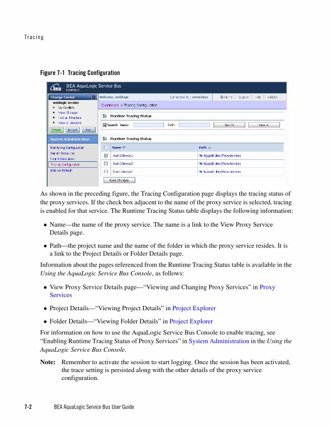
Trac ing
7-2 BEA AquaLogic Service Bus User Guide
Figure 7-1 Tracing Configuration
As shown in the preceding figure, the Tracing Configuration page displays the tracing status of the proxy services. If the check box adjacent to the name of the proxy service is selected, tracing is enabled for that service. The Runtime Tracing Status table displays the following information:
Name—the name of the proxy service. The name is a link to the View Proxy Service Details page.
Path—the project name and the name of the folder in which the proxy service resides. It is a link to the Project Details or Folder Details page.
Information about the pages referenced from the Runtime Tracing Status table is available in the Using the AquaLogic Service Bus Console, as follows:
View Proxy Service Details page—“Viewing and Changing Proxy Services” in Proxy Services
Project Details—“Viewing Project Details” in Project Explorer
Folder Details—“Viewing Folder Details” in Project Explorer
For information on how to use the AquaLogic Service Bus Console to enable tracing, see “Enabling Runtime Tracing Status of Proxy Services” in System Administration in the Using the AquaLogic Service Bus Console.
Note: Remember to activate the session to start logging. Once the session has been activated, the trace setting is persisted along with the other details of the proxy service configuration.
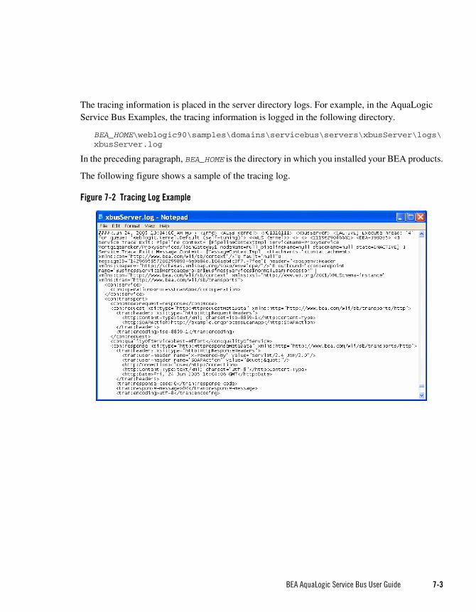
BEA AquaLogic Service Bus User Guide 7-3
The tracing information is placed in the server directory logs. For example, in the AquaLogic Service Bus Examples, the tracing information is logged in the following directory.
BEA_HOME\weblogic90\samples\domains\servicebus\servers\xbusServer\logs\xbusServer.log
In the preceding paragraph, BEA_HOME is the directory in which you installed your BEA products.
The following figure shows a sample of the tracing log.
Figure 7-2 Tracing Log Example

Trac ing
7-4 BEA AquaLogic Service Bus User Guide

BEA AquaLogic Service Bus User Guide 8-1
C H A P T E R 8
UDDI
Overview of BEA AquaLogic Service Bus and UDDIUniversal Description, Discovery and Integration (UDDI) registries are used in an enterprise to share Web services. Using UDDI services helps companies organize and catalog these Web services for sharing and reuse in the enterprise or with trusted external partners.
A UDDI registry service for Web services is defined by the UDDI specification available at:
http://www.oasis-open.org/committees/uddi-spec/doc/tcspecs.htm#uddiv3
This specification is a standard on which UDDI registries are based and provides the details on how to publish and locate information about Web services using UDDI. The specification does not define run-time aspects of the services (it is only a directory of the services). UDDI provides a framework in which to classify your business, its services, and the technical details about the services you want to expose.
Publishing a service to a registry requires knowledge of the service type and the data structure representing that service in the registry. A registry entry has certain properties associated with it and these property types are defined when the registry is created. You can publish your service to a registry and make it available for other organizations to discover and use. Proxy services developed in BEA AquaLogic Service Bus can be published to a UDDI registry.AquaLogic Service Bus can interact with any UDDI 3.0 compliant registry. BEA provides the AquaLogic Service Registry.

UDDI
8-2 BEA AquaLogic Service Bus User Guide
Figure 8-1 AquaLogic Service Bus integration with UDDI
AquaLogic Service Bus’ Web-based interface to AquaLogic Service Registry makes the registry accessible and easy to use. In working with UDDI, AquaLogic Service Bus promotes the reuse of standards based Web services. In this way, AquaLogic Service Bus registry entries can be searched for and discovered and used by a wider audience. Web services and UDDI are built on a set of standards, so reuse promotes the use of acceptable, tested Web services and application development standards across the enterprise. The Web services and interfaces can be catalogued by type, function, or classification so that they can be discovered and managed more easily.
Basic Concepts of the UDDI SpecificationUDDI is based upon several established industry standards, including HTTP, XML, XML Schema (XSD), SOAP, and WSDL. The latest version of the UDDI specification is available at:
http://www.oasis-open.org/committees/uddi-spec/doc/tcspecs.htm#uddiv3
The UDDI specification describes a registry of Web services and its programmatic interfaces. UDDI itself is a set of Web services. The UDDI specification defines services that support the description and discovery of:
Businesses, organizations, and other Web services providers
The Web services they make available
The technical interfaces that can be used to access and manage those services
Benefits of Using a UDDI Registry with AquaLogic Service BusA UDDI registry stores data and metadata about business services. It is a standards-based library of catalogued and managed information about Web services for discovery and reuse by other

Overv iew of BEA AquaLogic Se rv ice Bus and UDDI
BEA AquaLogic Service Bus User Guide 8-3
applications. UDDI offers several benefits to IT managers at both design time and run time, including increasing code reuse. It also provides benefits to developers, including the following:
Improves infrastructure management by publishing information about proxy services to the registry and categorizes the services for discovery. Thus growing a portfolio of services making it easier to understand and manage relationships among services, component versioning, and dependencies.
Services can be imported from a registry to configure the parameters required to invoke the Web service and the necessary transport and security protocols.
Promotes the use of standards-based Web services and business services development in business applications and provides a link to a library of resources for Web services developers. This decreasing the development lifecycle and improves productivity. It also increases the prospect of interoperability between business applications by sharing standards-based resources.
Provides a user friendly interface for searching and discovering Web services. You can search on user specified criteria.
Introduction to UDDI EntitiesUDDI uses a specific data model to represent entities that define organizations and services. Figure 8-2 shows the relationship between different UDDI entities.

UDDI
8-4 BEA AquaLogic Service Bus User Guide
Figure 8-2 UDDI Entities Representing Organizations and Services
A high-level overview of the UDDI entities is provided.
Table 8-1 High-Level Description of UDDI Entities
Business Entity An organization or group of people that own and provide the services.It can be described by a set of names, descriptions, contact details for the service provider, a set of categories that represent the business entity’s features, unique identifiers, discovery URLs.
Business Service A business service represents functionality or resources provided by business entities. It is described by a name, a description, and a set of categories that represent the function of the service. It is not necessarily a Web service.

Overv iew of BEA AquaLogic Se rv ice Bus and UDDI
BEA AquaLogic Service Bus User Guide 8-5
For more information on the UDDI data model and entities used in UDDI, see Introduction to BEA AquaLogic Service Registry in BEA AquaLogic Service Registry 2.0 User’s Guide.
PrerequisitesBefore using AquaLogic Service Bus with a UDDI registry you must perform the following tasks:
AquaLogic Service Registry must be installed and running. For information on how to install BEA AquaLogic Service registry 2.0, see Installation, in BEA AquaLogic Service Registry 2.0 Installation Guide.
AquaLogic Service Bus must be installed and running. For information on how to install BEA AquaLogic Service Bus 2.1, see Preparing for your installation, in BEA AquaLogic Installation Guide.
CertificationAquaLogic Service Bus works with any UDDI registry that is fully compliant with the version 3 implementation of UDDI (Universal Description, Discovery and Integration).
AquaLogic Service Registry 2.0 is a version 3 UDDI-compliant registry and is certified to work with AquaLogic Service Bus.
FeaturesThe AquaLogic Service Bus Console provides you with access to any version 3 compliant UDDI registry once it has been set up to work with AquaLogic Service Bus. The following features are available:
Binding Template A binding template represents the technical details of how to invoke a business service. A business service can contain one or more binding templates. It is described by an Access Point representing the service endpoint (the endpoint URI and protocol specification), tModel instance information, and categories to reference specific features of the binding template
tModel This is the technical model describing how services must be represented in the UDDI registry.It is described by name, description, an overview document (a reference to a document specifying the purpose of the tModel), categories, and identifiers (to uniquely identify the tModel).
Table 8-1 High-Level Description of UDDI Entities

UDDI
8-6 BEA AquaLogic Service Bus User Guide
Configure AquaLogic Service Bus to work with one or more version 3 UDDI compliant registries.
The import feature allows you to search for specific services in a registry or list all services available. You can search on business entity, service name pattern, or both, and then make your selection from the results list.
Import selected business services from a registry.
Publish selected AquaLogic Service Bus proxy services to the registry.
For more information on how to configure and search the registry, import business services to AquaLogic Service Bus, and how to publish proxy services to a UDDI registry, see the following topics in System Administration in Using the AquaLogic Service Bus Console:
Configuring a UDDI Registry
Importing a Business Service from UDDI Registry
Publishing a Proxy Service to a UDDI Registry
What is the BEA AquaLogic Service Registry?BEA AquaLogic Service Registry is a fully version 3 compliant implementation of UDDI and is a key component of a Service Oriented Architecture (SOA).
Note: AquaLogic Service Registry is not provided with AquaLogic Service Bus.It is licensed independently from Systinet and BEA.
A UDDI registry provides a standards-based foundation infrastructure for locating services, invoking services, and managing metadata about services (security, transport or quality of service). Using the Registry Console you can browse and publish registry content. The Registry Console is the primary console for administrators to perform registry management. You can launch the ALSR console in a Web browser by opening the following URL: http://hostname:port/uddi/web, where Host name and port are defined when AquaLogic Service Registry is installed. The default port is 8080. For more information on the management of AquaLogic Service Registry, particularly configuring the registry and managing permissions, approval, and replication, see the BEA AquaLogic Service Registry Administrator’s Guide.
Sample Business Scenario for AquaLogic Service Bus and UDDIThe following are two sample business scenario that highlight the benefit of using UDDI.

Overv iew of BEA AquaLogic Se rv ice Bus and UDDI
BEA AquaLogic Service Bus User Guide 8-7
Basic Proxy Service Communication with a UDDI RegistryThis scenario describes how you can use AquaLogic Service Bus to import services form a registry and then publish the services back to a registry as part of an AquaLogic Service Bus proxy service.
AquaLogic Service Bus imports business services from a UDDI registry. Proxy services are configured to communicate with the business services in the Message Flow. The proxy services themselves can be published back to the registry and made available for use by others.
Figure 8-3 Proxy Service Communication with a UDDI Registry
Cross-Domain Deployment in AquaLogic Service BusThis scenario describes cross-domain deployment using AquaLogic Service Bus. An AquaLogic Service Bus application in one domain wants to invoke another AquaLogic Service Bus service in another domain at run time.
An instance of AquaLogic Service Bus is deployed in each of two domains. The AquaLogic Service Bus Proxy service (P1) is configured in domain (D1). The AquaLogic Service Bus Proxy service (P2) in domain (D2) wants to access proxy service (P1). As the domains can not communicate directly with each other, P2 in D2 can not discover P1 in D1. The AquaLogic Service Bus import/export feature does not support run-time discovery of services in different domains, but publishing the service to a publicly available UDDI registry allows for the discovery of the service in any domain. Once P1 is made available in the UDDI registry it can be invoked at run time (for example, get a stock quote) and imported as a business services in another AquaLogic Service Bus proxy service.
When importing and exporting from different domains you must have network connectivity. A proxy service might reference schemas located in the repository of a different domain, in which

UDDI
8-8 BEA AquaLogic Service Bus User Guide
case it needs HTTP access to the domain to import using the URL. In the absence of connectivity an error message will be returned.
Figure 8-4 Sample Business Case of Cross Domain Deployment
Using AquaLogic Service Bus and UDDIYou can use the AquaLogic Service Bus Console to
Publish information about any proxy service to a registry, including the following service types: WSDL, messaging, any SOAP, and any XML.
Search a registry for information about a service and discover the service.
Configure a registry to allow users to publish services and import services.
Import Web services and integrate them with your application.
Typical WorkflowFigure 8-5 shows the typical workflow for using UDDI with AquaLogic Service Bus.

Conf igur ing a Reg is t r y
BEA AquaLogic Service Bus User Guide 8-9
Figure 8-5 Typical Workflow
Configuring a RegistryYou can configure a UDDI registry, make it available in AquaLogic Service Bus, and then publish AquaLogic Service Bus proxy services to it or import business services from the registry to be used in a proxy service. You must be in an active AquaLogic Service Bus session in the AquaLogic Service Bus Console to configure the registry.

UDDI
8-10 BEA AquaLogic Service Bus User Guide
The following table describes the configuration properties for a UDDI registry. Every registry has a set of properties that must be configured. When configuring a UDDI registry, the Inquiry URL is required. The Service account is also required to permit access to the registry when publishing a service.When specifying the configuration settings, the following cases are worth noting:
To do an anonymous read only of the registry, you need to specify only an Inquiry URL and nothing else.
To publish with authentication, you must specify the Inquiry URL, the Publish URL, Security URL, and the Service Account.
To do an Inquiry and get a specific view of the contents of the registry, you must specify the Inquiry URL, the Security URL, and a service account.
When publishing services to AquaLogic Service Registry, to gain access to the registry, you must be authenticated and have a valid username and password. The username and password is implemented in AquaLogic Service Bus as a service account resource (using credentials). Service accounts must be defined before configuring proxy services so that the authentication criteria is
Table 8-2 UDDI Registry Configuration Settings
Name* This is the name of the registry. The name was assigned to it when it was first published.Select the registry name to edit the details for the registry. You can edit the Inquiry URL, Publish URL, Security URL, and the Service Account, but not the name of the registry.
Inquiry URL* This is the URL used to locate and import a service. The Inquiry URL is required. To read from a registry, you only need to specify a name and Inquire URL.
Publish URL* This is the URL used to publish a service. When publishing a service you must also specify a security URL and specify the service account associated with the registry.
Security URL This URL is used to get an authentication token so that you can publish to the registry. You must specify a publish URL and a security URL if you have a service account defined.
Service Account A service account is required for publishing services to a registry. This account grants access to the registry using a username and password. A registry can have a single service account associated with it.When using a service account, you must also specify a security URL.
Options Delete is the only option defined for the registry.

Pub l i shi ng a P roxy Serv i ce to a UDDI Reg is t r y
BEA AquaLogic Service Bus User Guide 8-11
set up to work with a service during the configuration of the proxy service. To create a service account in AquaLogic Service Bus, see “Adding a Service Account” in Service Accounts in Using the AquaLogic Service Bus Console.
You can set up registries with multiple username and passwords allowing different users to have different permissions based on the service account. Permissions in AquaLogic Service Registry were developed so that administrators can manage users’ rights in BEA AquaLogic Service Registry and create views into the registry, specific to the needs of the different user types. User permissions set in AquaLogic Service Bus govern access to the registries, their content, and the functionality available to you.
Publishing a Proxy Service to a UDDI RegistryYou can use the AquaLogic Service Bus Console to publish proxy services to AquaLogic Service Registry You must have an account set up in AquaLogic Service Registry to do this. You can publish any proxy service to a UDDI registry. The service types and transports are listed in Table 8-3.
You can select the Business Entity under which a service is to be published. Business Entity Administration (including creation, removal, update and deletion of entities) is done using the management console provided by the registry vendor (the Business Service Console in the case of AquaLogic Service Registry). The first time you publish to a registry you must load the tModels to that registry. This is done at the same time you configure the publishing details in the AquaLogic Service Bus Console. For more information on how to publish to a UDDI registry, see “Publishing a Proxy Service to a UDDI Registry” in System Administration in Using the AquaLogic Service Bus Console.
Table 8-3 Service Types and Transports for a Proxy Service
Service Type Transports
WSDL HTTP(S), JMS
Any SOAP HTTP(S), JMS
Any XML HTTP(S), JMS, Email, File, FTP
Messaging HTTP(S), JMS, Email, File, FTP
Note: Messaging services can have different content for requests and responses, or can have no response at all (one-way messages). Email, File, and FTP must be one-way.

UDDI
8-12 BEA AquaLogic Service Bus User Guide
AquaLogic Service Bus works with any UDDI version 3 registry. Generally in a large organization the systems administrator is responsible for creating and setting up the registries. The service account must be set up before a service (proxy service in AquaLogic Service Bus) can be published as a business entity to the registry.
Importing a Service from a RegistryYou can import services from a registry as AquaLogic Service Bus business services. When importing a WSDL-based service, if multiple UDDI binding templates are encountered, AquaLogic Service Bus creates a different business service for each binding template.
Access to registries in AquaLogic Service Bus is established by someone who has AquaLogic Service Bus system administration privileges for the UDDI registries. The registry entries automatically appear in the Import page of the AquaLogic Service Bus Console. When importing, you make a selection from the list of available registries. To discover a service in a registry you must query a specific registry. Entries in registries are unique. This query is performed when you specify what registry you want to use for importing a service.
You can import the following business services types from a UDDI registry into AquaLogic Service Bus:
WSDL over HTTP binding.When multiple UDDI binding templates are encountered, a business service is create for each binding template.
SOAP or XML binding over HTTP, or XML.
Services that are categorized as AquaLogic Service Bus services. These are AquaLogic Service Bus proxy services that are published to a UDDI registry. This feature is primarily used in multi-domain AquaLogic Service Bus deployments where proxy services from one domain need to discover and route to proxy services in another domain.
For information on how to use the AquaLogic Service Bus Console to import services from a UDDI registry, see “Importing a Business Service from a UDDI Registry” in System Administration in Using the AquaLogic Service Bus Console.
When a service is updated, you must re-import the service from the registry to get the most up to date version.
Services have documents associated with them and these documents can include a number of other documents (schemas, policies, and so on.). On import, the UDDI registry points to the document location based on the inquiry URL of the service. When a document that includes or references other resources is located, all of the referenced information and each included item is added as a separate resource in AquaLogic Service Bus.

Mapping AquaLog ic Se rv ice Bus P roxy Se rv ices to UDDI Ent i t i es
BEA AquaLogic Service Bus User Guide 8-13
Business Entity and pattern are the criteria used to search for a service in a registry. For example, you can enter foo%, when searching for a service. Services published by AquaLogic Service Bus have specific tmodel keys identifying the service that are used when searching for the service in the registry.
Import automatically tries to connect to a registry as you are attempting to get the list of business entities from the registry. The Business Entity is the highest level of organization in the registry, though you can use other search criteria, such as business, application type, and so on. If you require authentication, then you need a username and password which you must get from your systems Administrator.
Related ReferencesTechnical Notes can be found at http://www.oasis-open.org/committees/uddi-spec/doc/tns.htm. One of the most important Technical Notes is Using WSDL in a UDDI Registry.
UDDI product and development tool information is available at the OASIS UDDI Solutions page at http://uddi.org/solutions.html.
The UDDI specifications can be found at http://www.oasis-open.org/committees/uddi-spec/doc/tcspecs.htm.The specification defines the following:
– SOAP APIs that applications use to query and to publish information to a UDDI registry
– XML Schema schemata of the registry data model and the SOAP message formats
– WSDL definitions of the SOAP APIs
– UDDI registry definitions (tModels) of various identifier and category systems that may be used to identify and categorize UDDI registrations
Mapping AquaLogic Service Bus Proxy Services to UDDI EntitiesAquaLogic Service Bus proxy service attributes must be mapped to the data model supported by the UDDI registry to allow a proxy service to be published as a UDDI business entity. The following table shows the service types, message types, and transports relevant to the UDDI registry mapping for an AquaLogic Service Bus proxy service.

UDDI
8-14 BEA AquaLogic Service Bus User Guide
Proxy services have attributes in common and also attributes that are specifically defined by the transport protocols used by the service and the type of service. Each proxy service can deliver messages of a certain type.
The primary relevant entities in UDDI are:
businessService—this represents the service as a whole and contains high-level general information about the service.
bindingTemplate—this contains information for accessing the service.
tModels—tModels are used to supply the individual attributes for categorizing and defining the service.
Figure 8-6 shows how WSDL-based services are mapped to UDDI business entities.
Table 8-4 Proxy Service Attributes and Service Types
Service Type Message Content Type Transports
WSDL SOAP or XML (with attachment) HTTP(S), JMS
Any SOAP Untyped SOAP (with attachment) HTTP(S), JMS
Any XML Untyped XML (with attachment) HTTP(S), JMS, Email, File, FTP
Messaging Binary, Text, MFL, XML (schema) HTTP(S), JMS, Email, File, FTP
Note: Optional parts are listed in parenthesis. Messaging services can have different content for requests and responses, or can have no response at all (one-way messages). Email, File, and FTP must be one-way.

Mapping AquaLog ic Se rv ice Bus P roxy Se rv ices to UDDI Ent i t i es
BEA AquaLogic Service Bus User Guide 8-15
Figure 8-6 WSDL Service to UDDI Mapping
The technical note Using WSDL in a UDDI registry, version 2.0.2, at http://www.oasis-open.org/committees/uddi-spec/doc/tns.htm, is used as the basis for publishing WSDL-based proxy services to the UDDI registry. This document is also used as a reference point for publishing non WSDL-based services. The document and the base UDDI specification describe the canonical technical models (tModels) used to describe UDDI entities. To publish AquaLogic Service Bus proxy services as entities in the UDDI registry, you must add additional canonical tModels to support some of the AquaLogic Service Bus specific constructs. Not all attributes of an AquaLogic Service Bus proxy service are useful when searching for a service, such as service type and transport details. These attributes do not categorize the service, they are useful things to know about a service and are configuration details of the service once it has been discovered. These configuration details are mapped to the business service binding template tmodelinstanceDetails section.Other attributes specifically identify a service and can be used as the search criteria for the service. These attributes are mapped using keyed references to tModels with values in the category bag of the binding template.
An example of how AquaLogic Service Bus maps to UDDI is shown in Figure 8-7.

UDDI
8-16 BEA AquaLogic Service Bus User Guide
Figure 8-7 AquaLogic Service Bus to UDDI Mapping
UDDI Mapping Details for an AquaLogic Service Bus Proxy ServiceAquaLogic Service Bus high-level proxy service information maps into the Business Service as follows:
Name and Description map to businessService elements.
There is a Special keyed Reference Group for AquaLogic Service Bus properties. An example of a key is uddi:bea.com:attributes:aqualogicservicebus.
AquaLogic Service Bus type (WSDL, SOAP, XML, and Mixed) and Instance are mapped to keyedReferences in the service category bag. An example of a key is uddi:bea.com:servicetype.
An AquaLogic Service Bus Instance maps to a keyedReference in the AquaLogic Service Bus keyedReferenceGroup (Name = “AquaLogicServiceBus”, Values = URL of the AquaLogic Service Bus instance). This instance serves two purposes:
– As a maker to indicate that this service is in fact hosted by an AquaLogic Service Bus server.
– To contain the URL of the AquaLogic Service Bus instance.
Listing 8-1 shows a mapping of high-level proxy service information to a business service.

Mapping AquaLog ic Se rv ice Bus P roxy Se rv ices to UDDI Ent i t i es
BEA AquaLogic Service Bus User Guide 8-17
Listing 8-1 Sample Proxy Service to Business Service Mapping
<keyedReferenceGroup tModelKey=”uddi:bea.com:servicebus:properties”><keyedReference tModelKey=“uddi:bea.com:servicebus:servicetype”
keyName=“Service Type”keyValue=“SOAP”/>
<keyedReference tModelKey=“uddi:bea.com:servicebus:instance”keyName=“Service Bus Instance”keyValue=“http://FOO02.amer.bea.com:7001”/>
</keyedReferenceGroup
Note: The key for the businessService created when a proxy service is published is a publisher assigned key name. It is derived from the AquaLogic Service Bus domain name, the path of the proxy service, and the proxy service name. It takes the following form: uddi:bea.com:servicebus:<domainname>:<path>:<servicename>.
For example, an AquaLogic Service Bus domain, AnonESB, contains a project Proxies, which contains a folder named Accounting, which in turn contains a proxy service called PayoutProxy. When PayoutProxy is published to UDDI, its businessService is created with the following key: uddi:bea.com:servicebus:AnonESB:Proxies:Accounting:PayoutProxy.
AquaLogic Service Bus detailed proxy service information maps into the binding template as follows:
The Endpoint URI maps to the access point.
The Marker tModel for each transport maps to tModelInstanceDetails.
– Transport tModels for HTTP, JMS, File, FTP, Email. New tModels are packaged with AquaLogic Service Bus to support JMS and file transports.
– Detailed AquaLogic Service Bus configuration information maps to instanceParms.
The Market tModel for each service type maps to the tModelInstanceDetails.This includes the following:
– Protocol tModels for WSDL, any SOAP, any XML, Messaging. New tModels are packaged with AquaLogic Service Bus to support anySOAP, anyXML, and Messaging.
– WSDL maps via WSDL to UDDI technology note.
– Messaging has detailed configuration information that maps to InstanceParms.
Listing 8-2 shows a detailed information mapping to the binding template.

UDDI
8-18 BEA AquaLogic Service Bus User Guide
Listing 8-2 Sample Detailed Mapping to the Binding Template
<bindingTemplate bindingKey=“uddi:…” serviceKey=“uddi:…”><accessPointuseType=“endPoint”>file:///c:/temp/in3</accessPoint><tModleInstanceDetails>
<tModleInstanceInfo tModelKey= “uddi:uddi.org:transport:file”><InstanceDetails><InstanceParms><ALSBInstanceParms
xmlns=”http://www.bea.com/wli/sb/uddi”><property name=“fileMask” value=“*.*”/><property name=“sortByArrival” value=“false”/> </ALSBInstanceParms>
</InstanceParms></InstanceDetails>
</tModelInstanceInfo><tModleInstanceInfo tModelKey=“uddi:bea.com:servicebus:protocol:
messagingservice”><InstanceDetails><InstanceParms><ALSBInstanceParms
xmlns=”http://www.bea.com/wli/sb/uddi”><property name=“requestType” value=“XML”/><property name=“RequestSchema” value=“http://domain.com:7001
/sbresource?SCHEMA%2FDJS%2FOAGProcessPO”/><property name=“RequestSchemaElement”
value=“PROCESS_PO”/><property name=“responseType” value=“None”/></ALSBInstanceParms>
</InstanceParms></InstanceDetails>
</tModelInstanceInfo></tModelInstanceDetails>
Transport AttributesEach of the transport types in the uddi:uddi.org:transport:* group has a different set of detailed metadata. (See Table 8-4, “Proxy Service Attributes and Service Types,” on page 8-14.) This metadata provides configuration details of the transport for the proxy service. It is not useful for characterizing the service nor useful in querying the service. However, after the service has been discovered, this data is needed to access the service. The metadata is represented by an XML string and is located in the instanceParms field in tModelInstanceInfo.
For example, if you are mapping a proxy service that uses the HTTP transport, and as part of the HTTP configuration you need to describe some detailed configuration details, including the required client authorization and the request and response character encoding, the following

Mapping AquaLog ic Se rv ice Bus P roxy Se rv ices to UDDI Ent i t i es
BEA AquaLogic Service Bus User Guide 8-19
listing provides an example of what must appear in the bindingTemplate tModelInstanceDetails.
Listing 8-3 Example of tModelInstanceDetails
<tModelInstanceDetails><tModelInstanceInfo tModelKey="uddi:uddi.org:transport:http">
<instanceDetails><instanceParms><ALSBInstanceParms xmlns="http://www.bea.com/wli/sb/uddi">
<property name="basic-auth-required" value="true"/><property name="request-encoding" value="iso-8859-1"/><property name="response-encoding" value="utf-8"/><property name="Scheme" value="http"/>
</ALSBInstanceParms></instanceParms>
</instanceDetails></tModelInstanceInfo>
</tModelInstanceDetails>
Note: For each transport, the service endpoint is always stored in the bindingTemplate’s accessPoint field.
Table 8-5 is organized by transport type and lists the tModelKey and InstanceParms used by each of the transports.
Table 8-5 Transport Attributes
Transport tModelKey InstanceParms
HTTP uddi:uddi.org:transport:http • Client Authentication [None, Basic, Client Cert (HTTPS only)]
• Request encoding
• Response encoding
JMS uddi:uddi.org:transport:jms • Destination Type [Queue, Topic]
• Response required, Response URI
• Response Message Type [Bytes, Text]
• Request encoding
• Response encoding

UDDI
8-20 BEA AquaLogic Service Bus User Guide
Service Type AttributesTable 8-6 provides a high-level description of each of the service types.
File uddi:uddi.org:transport:file • File Mask
• Sort by Arrival [Boolean]
• Request Encoding
FTP uddi:uddi.org:transport:ftp • File Mask
• Sort by Arrival [Boolean]
• Transfer Mode [Text, Binary]
• Request Encoding
Email1 uddi:uddi.org:transport:smtp • Attachment supported [Boolean]
• Request Encoding
1. The accessPoint in the Binding Template for an Email Transport uses the standardmailto URL format: mailto:name@some_server.com This is different than the oneconfigured for the proxy service in AquaLogic Service Bus, which is a URL orientedtoward reading email.It is not be possible to derive this mailto URL from the proxyservice definition as the server name is not known. For example, if the proxy service isdefined to read from a POP3 server, it might be defined with a URL such asmailfrom:pop3.bea.com. When publishing such a proxy service, a dummy server isadded. In the above example, the published URL will take the formmailto:some_name@some_server.com.
Table 8-5 Transport Attributes
Transport tModelKey InstanceParms

Canon ical tModels Suppor t i ng AquaLogic Se rv i ce Bus Se rv i ces
BEA AquaLogic Service Bus User Guide 8-21
Canonical tModels Supporting AquaLogic Service Bus ServicesThe AquaLogic Service Bus-UDDI mapping introduces a number of new canonical tModels that are used to represent AquaLogic Service Bus metadata and relationships. These tModels must be
Table 8-6 Service Type Attributes
Service Description
WSDL WSDL based proxies map to UDDI based on the Using WSDL in a UDDI Registry, version 2.0.2 technical note, which is available at the following URL:
http://www.oasis-open.org/committees/uddi-spec/doc/tn/uddi-
spec-tc-tn-wsdl-v202-20040631.htm.
Any SOAP A simple marker protocol in the tModel in the bindingTemplate’s tModelInstanceDetails, as well as in the categoryBag, defines the Any Soap attributes.
Any XML A simple marker protocol tModel in the bindingTemplate’s tModelInstanceDetails, as well as in the categoryBag defines the Any XML attributes. This is a new detailed tModel.
Messaging Services
A simple marker protocol tModel in the bindingTemplate’s tModelInstanceDetails, defines the messaging services attributes. This is a new detailed tModel.Unlike the other service types, messaging services have additional configuration information associated with them, which provide details about the request and response messages. The configuration details are represented as XML data in the InstanceParms data for the following tModel reference in the tModelInstanceInfo:
• Input message format (XML, Text, Binary, MFL)
• URL of input message Schema in AquaLogic Service Bus (optional, if input message is XML)
• URL of input message MFL in AquaLogic Service Bus (if input message is MFL)
• Output message format (none, XML, Text, Binary, MFL)
• URL of output message Schema in AquaLogic Service Bus (optional, if output message is XML)
• URL of output message MFL in AquaLogic Service Bus (if output message is MFL)

UDDI
8-22 BEA AquaLogic Service Bus User Guide
registered in the UDDI registry to support this mapping. You can create these tModels in AquaLogic Service Registry under the administrator ID.
The following table provides a summary of the new tModels.
Table 8-7 AquaLogic Service Bus tModels
Name Value Description
CategorizationGroup tModel Types
bea-com:servicebus:properties Used to describe very specific attributes of an AquaLogic Service Bus service. In the data model it is used in the business service category bag.
Categorization tModel Types
bea-com:servicebus:serviceType WSDL, SOAP, XML, Messaging Service
Describes the service type of the AquaLogic Service Bus service.
bea-com:servicebus:instance URL of AquaLogic Service Bus Console
Describes the service instance in AquaLogic Service Bus responsible for publishing the service to UDDI.
Transport tModel Types
uddi-org:jms Describes the type of transport used by the service. A reference to it is found in the accessPoint attribute of the business service binding template.
uddi-org:file Describe the type of transport used to invoke the service. A reference to it is found in the accessPoint attribute of the business service binding template.
Protocol tModel Types
bea-com:servicebus:anySoap Used to describe the type of protocol used to access the service. It designates services having a SOAP message but not defined by a WSDL or schema. The message body content is determined dynamically by the application.

Example
BEA AquaLogic Service Bus User Guide 8-23
ExampleThe following is an example of the mapping for a Messaging Service, running over JMS with the request being XML with a Schema and the response being a text message.
Listing 8-4 Sample Messaging Service Mapping
<businessService serviceKey="uddi:bea.com:servicebus:Domain:Project:JMSMessaging" businessKey="uddi:9cb77770-57fe-11da-9fac-6cc880409fac" xmlns="urn:uddi-org:api_v3">
<name>JMSMessagingProxy</name> <bindingTemplates><bindingTemplate bindingKey="uddi:4c401620-5ac0-11da-9faf-6cc880409fac" serviceKey="uddi:bea.com:servicebus:
Domain:Project:JMSMessaging"><accessPoint useType="endPoint">jms://server.com:7001/weblogic.jms.XAConnectionFactory/
ReqQueue</accessPoint> <tModelInstanceDetails><tModelInstanceInfo tModelKey="uddi:uddi.org:transport:jms">
<instanceDetails><instanceParms>
<ALSBInstanceParms
bea-com:servicebus:anyXML Used to describe the type of protocol used to access the service. It designates services having an XML message but not defined by a WSDL or schema. The message body content is determined dynamically by the application.
bea-com:servicebus:messagingService Used to describe the type of protocol used to access the service. It designates services where the request message can be any XML (with or without schema), text, binary, or MFL and whose response messge can be any of the above or none. The message body content is determined dynamically by the application.
Table 8-7 AquaLogic Service Bus tModels
Name Value Description

UDDI
8-24 BEA AquaLogic Service Bus User Guide
xmlns="http://www.bea.com/wli/sb/uddi"><property name="is-queue" value="true"/> <property name="request-encoding" value="iso-8859-1"/>
<property name="response-encoding" value="utf-8"/>
<property name="response-required" value="true"/>
<property name="response-URI" ="jms://server.com:7001/.jms.XAConnectionFactory/
RespQueue"/> <property name="response-message-type" value="Text"/>
<property name="Scheme" value="jms"/> </ALSBInstanceParms>
</instanceParms> </instanceDetails>
</tModelInstanceInfo><tModelInstanceInfo
tModelKey="uddi:bea.com:servicebus:protocol:messagingservice">
<instanceDetails><instanceParms>
<ALSBInstanceParms xmlns="http://www.bea.com/wli/sb/uddi"><property name="requestType" value="XML"/> <property name="RequestSchema"
value="http://server.com:7001/sbresource?SCHEMA%2FDJS%2FOAGProcessPO"/>
<property name="RequestSchemaElement" value="PROCESS_PO_007"/>
<property name="responseType" value="Text"/> </ALSBInstanceParms>
</instanceParms> </instanceDetails>
</tModelInstanceInfo></tModelInstanceDetails>
</bindingTemplate></bindingTemplates>
<categoryBag><keyedReferenceGroup tModelKey="uddi:bea.com:servicebus:properties">
<keyedReference tModelKey="uddi:bea.com:servicebus:servicetype" keyName="Service Type" keyValue="Mixed" />
<keyedReference tModelKey="uddi:bea.com:servicebus:instance" keyName="Service Bus Instance" keyValue="http://cyberfish.bea.com:7001" />
</keyedReferenceGroup>

Example
BEA AquaLogic Service Bus User Guide 8-25
</categoryBag></businessService>

UDDI
8-26 BEA AquaLogic Service Bus User Guide

BEA AquaLogic Service Bus User Guide A-1
A P P E N D I X A
Tuning AquaLogic Service Bus
This appendix provides AquaLogic Service Bus tuning tips.
Whenever possible, set the logging level to warning. You set the logging level in the WebLogic Server Administration Console. For more information, see Servers: Logging: General in the WebLogic Server Administration Console Online Help. The following code displays the output server config.xml file when the logging level is set to warning. For more information on logging, see “Log” in Proxy Services: Actions in the Using the AquaLogic Service Bus Console.
<server>
<name>AdminServer</name>
<log>
<file-min-size>5000</file-min-size>
<log-file-severity>Warning</log-file-severity>
<log-file-filter xsi:nil="true"></log-file-filter>
<stdout-severity>Off</stdout-severity>
<stdout-filter xsi:nil="true"></stdout-filter>
<domain-log-broadcast-severity>Error</domain-log-broadcast-severity>
<domain-log-broadcast-filter xsi:nil="true"></domain-log-broadcast-filter>
<memory-buffer-severity>Error</memory-buffer-severity>
<memory-buffer-filter xsi:nil="true"></memory-buffer-filter>
</log>

Tun ing AquaLog ic Se rv ice Bus
A-2 BEA AquaLogic Service Bus User Guide
</server>
Group JMS queues on different JMS servers based on message loads. Different JMS servers use different file stores, which you can distribute to separate disk volumes. For more information, “Adding a Business Service” in Business Services in the Using the AquaLogic Service Bus Console and pay particular attention to the JMS configuration information.
If you are using an Oracle database as a JMS persistent store, it is recommended that you use a 10g database and ensure that it has sufficient JDBC connections. Create a JDBC store on a separate schema to use a separate tablespace.
If you do not require monitoring for a proxy or business service, disable the monitoring capability. For more information, see “Overview of Monitoring” in Monitoring in the Using the AquaLogic Service Bus Console.
If possible, set the routing data in the JMS message properties. AquaLogic Service Bus does not deserialize message content until the content is explicitly accessed in the pipeline. For example, if the content is an XML document, XML parsing does not happen until an XQuery or XSLT operation happens in the pipeline. For more information about working with the message context in the message flow, see Message Context in the Using the AquaLogic Service Bus Console.
If you need to extract some of the inbound header elements for processing, you should specify that AquaLogic Service Bus retrieves specific header elements instead of all the elements.
Where possible, use the insert action instead of the assign action. The insert action uses “in-place” modification semantics making it more performant compared to the assign action. For information on configuring actions, see “Adding an Action” in Proxy Services: Actions in the Using the AquaLogic Service Bus Console.
Use AquaLogic Service Bus clustering and WebSphere MQ clustering to achieve scalability.
If a front end application invokes AquaLogic Service Bus synchronously, AquaLogic Service Bus can use the sync-async feature to communicate with WebSphere MQ synchronously. On the WebSphere MQ side, a request and a response queue is set up. AquaLogic Service Bus sends a request to the request queue and waits for a response from the response queue. To achieve improved performance, you can use a dedicate work manager for the response Message Driven Bean. You configure the dedicate work manager in the WebLogic Server Administration Console. For more information, see Work Manager in the WebLogic Server Administration Console Online Help. The following code displays the output server config.xml file after the dedicate work manager is configured.

BEA AquaLogic Service Bus User Guide A-3
<self-tuning>
<min-threads-constraint>
<name>minThreadsConstraint</name>
<target>AdminServer</target>
<count>20</count>
</min-threads-constraint>
<work-manager>
<name>MQWorkManager</name>
<target>AdminServer</target>
<min-threads-constraint> minThreadsConstraint </min-threads-constraint>
<ignore-stuck-threads>false</ignore-stuck-threads>
</work-manager>
</self-tuning>

Tun ing AquaLog ic Se rv ice Bus
A-4 BEA AquaLogic Service Bus User Guide

BEA AquaLogic Service Bus User Guide B-1
A P P E N D I X B
Debugging AquaLogic Service Bus
This section provides information about enabling debugging for different modules in AquaLogic Service Bus. You can enable and disable debugging by modifying the corresponding entries in the wlidebug.xml file, which is located in the root directory of the AquaLogic Service Bus domain. If the wlidebug.xml file is not in the root directory or if it has been deleted, it is created again without any contents when the server starts. The following listing provides an example of the contents of the wlidebug.xml file with debugging disabled for all modules (all entries set to false).
Listing B-1 wlidebug.xml File
<?xml version='1.0' encoding='UTF-8'?>
<java:wli-debug-logger xmlns:java="java:com.bea.wli.debug">
<n1:Name xmlns:n1="java:weblogic.diagnostics.debug">wlidebug</n1:Name>
<java:wli-management-debug>false</java:wli-management-debug>
<java:wli-monitoring-debug>false</java:wli-monitoring-debug>
<java:wli-management-dashboard-debug>false</java:wli-management-dashboard-debug>
<java:wli-config-debug>false</java:wli-config-debug>
<java:wli-config-transaction-debug>false</java:wli-config-transaction-debug>
<java:wli-config-deployment-debug>false</java:wli-config-deployment-debug>
<java:wli-config-component-debug>false</java:wli-config-component-debug>
<java:wli-sb-transports-debug>false</java:wli-sb-transports-debug>
<java:wli-sb-pipeline-debug>false</java:wli-sb-pipeline-debug>

Debugging AquaLog ic Ser v i ce Bus
B-2 BEA AquaLogic Service Bus User Guide
<java:wli-alert-manager-debug>false</java:wli-alert-manager-debug>
<java:wli-jms-reporting-provider-debug>false</java:wli-jms-reporting-provider-debug>
<java:wli-monitoring-aggregator-debug>false</java:wli-monitoring-aggregator-debug>
< java:wli-credential-debug >false</java:wli-credential-debug >
< java:wli-management-common-debug >false</java:wli-management-common-debug >
</java:wli-debug-logger>
Although debugging should be disabled during normal AquaLogic Service Bus operation, you may find it helpful to turn on certain debug flags while you are developing your solution and experimenting with it for the first time. For example, you may want to turn on the alert debugging flag when you are developing alerts and would like to investigate how the alert engine works.
Some of the available debug flags are:
wli-config-debug—Provides information on general aspects of AquaLogic Service Bus configuration.
wli-config-deployment-debug— Provides debug information on session creation, activation, and distribution of configuration in a cluster.
wli-config-transaction-debug—Provides low level debug information about changes made to in-memory data structures and files. This alert flag also generates server startup recovery logs.
wli-config-component-debug—Provides low level debug information about create, update, delete, and import operations.
wli-sb-transports-debug—Provides transport related debug information, including transport headers, which is printed per-message.
wli-sb-pipeline-debug—Prints errors that are generated within the pipeline.
wli-alert-manager-debug—Prints an evaluation of alerts.
All other debug flags are self explanatory.
For all flags, debug information is logged to the server log at {domaindir}/servers/{servername}/logs/{servername}.log, except for the

BEA AquaLogic Service Bus User Guide B-3
wli-monitoring-aggregator-debug flag. The wli-monitoring-aggregator-debug flag enables debugging for aggregator. This flag logs the aggregated document every minute and stores the log files in the {domain}\monitoring folder.
Note: Turning the wli-monitoring-aggregator-debug flag on generates large amounts of debug data. Therefore, you should only use this flag for debugging purposes for short periods of time.

Debugging AquaLog ic Ser v i ce Bus
B-4 BEA AquaLogic Service Bus User Guide

BEA AquaLogic Service Bus User Guide C-1
A P P E N D I X C
XQuery Implementation
This section provides information about the implementation of XQuery in AquaLogic Service Bus. The World Wide Web (W3C) specification for XQuery defines a set of language features and functions. AquaLogic Service Bus uses the BEA AquaLogic Data Services Platform XQuery engine. The BEA XQuery engine fully supports language features with one exception (modules) and also supports a robust subset of functions and adds a number of implementation-specific functions and language keywords.
AquaLogic Service Bus supports a number of functions that are enhancements to the XQuery specification, which you can recognize by their extended function prefix fn-bea:. For example, the full XQuery notation for an extended function is: fn-bea:function_name.
For a list of the supported functions and a description of each function, see BEA XQuery Implementation in the XQuery Developer's Guide.
Caution: The following functions listed in BEA XQuery Implementation in the XQuery Developer's Guide are not supported by AquaLogic Service Bus:
fn-bea:is-access-allowed
fn-bea:is-user-in-group
fn-bea:is-user-in-role
fn-bea:userid
fn-bea:async
fn-bea:timeout
fn-bea:get-property

XQuery Imp lementa t ion
C-2 BEA AquaLogic Service Bus User Guide
Note: It is recommended that you do not use the following functions—they are better covered by other language features:
fn-bea:if-then-else
fn-bea:QName-from-string
fn-bea:sql-like
Related TopicsBEA AquaLogic Data Services Platform is a service-oriented solution that enables enterprise information to be delivered and accessed as data services. To learn about the BEA AquaLogic Data Services Platform, see the product documentation Web site at the following URL:
http://e-docs.bea.com/aldsp/docs20/index.html