beacon light curtain installation manual - helm instrument€¦ · · 2015-11-06helm instrument...
TRANSCRIPT

Helm Instrument Company, Inc. 361 West Dussel Drive Maumee, Ohio 43537 USA 419/ 893-4356 Fax: 419/ 893-1371 www.helminstrument.com
Beacon Light Curtain
Installation Manual
Force Measurement and Control Solutions


Introduction Thank you for purchasing the RPH4 Series Safety Light Curtain (hereinafter referred to as "the RPH4"). This is the Instruction Manual describing the use of the RPH4. Always heed the following points when using the RPH4:
• Read this manual thoroughly and be sure you understand the information provided before attempting to operate the RPH4.
• It is assumed that the RPH4 will be used properly according to the installation environment, performance and function of the machine. Qualified personnel should conduct risk assessment on the machine and determine the suitability of this product before installation.
• Make sure that the personnel operating the RPH4 are knowledgeable about its’ operation and the machine on which it is installed.
• Keep the manual in a secure and convenient location and refer to it as necessary.
Regulations and Standards 1. The RPH4 has not received the type approval provided by Article 44-2 of the Industrial Safety and Health
Law of Japan. Therefore, it cannot be used in Japan as a safety device for pressing or shearing machines provided by article 42 of that law.
2. (1) The RPH4 is electro-sensitive protective equipment (ESPE) in accordance with European Union (EU) Machinery Directive Annex IV, B, Safety Components, Item 1.
(2) The RPH4 complies with the following regulations and standards:
1. EU regulations − Machinery Directive: Directive 98/37/EC − EMC Directive: Directive 89/336/EEC
2. European standard: EN61496-1 (TYPE 4 ESPE)
3. International standard: IEC61496-1 (TYPE 4 ESPE), IEC61496-2 (TYPE 4 AOPD)
(3) The RPH4 received the following approvals from the EU accredited body DEMKO: − EC Type-Examination in accordance with the EU Machinery Directive − Certificate of a Competent Body for EMC − Certificate of a Notified Body for DEMKO TYPE 4 ESPE (EN61496-1)
TYPE 4 AOPD (IEC61496-2) Use: EN954-1 Category B, 1, 2, 3, 4
(4) The RPH4 received the following approvals from the Third Party Assessment Body UL: − Certificate of UL listing for US and Canadian safety standards
Both of which are: TYPE 4 ESPE (IEC61496-1) TYPE 4 AOPD (IEC61496-2)
− Certificate of Programmable System (UL1998, IEC61496-1) 3. The RPH4 is designed according to the following standards. To make sure that the RPH4 complies with the
following standards and regulations, you are asked to design and use it as provided by any other related standards, laws, and regulations. Consult UL or other standardization bodies if you have any questions.
− EN415-4, prEN691, EN692, prEN693 (European standard) − OSHA 29 CFR 1910.212 (US Industrial Safety and Health Regulation) − OSHA 29 CFR 1910.217 (US Industrial Safety and Health Regulation) − ANSI B11.1~B11.19 (US standard) − ANSI/RIA 15.06 (US standard)
B-i

Notice Give sufficient safety considerations and make enough allowance with regard to ratings and functions of the system when using the RPH4 under following conditions:
(1) Conditions or environment not specified in this manual (2) Applications to devices and facilities requiring special safety precautions, such as; nuclear energy control,
railway, aircraft, vehicles, combustion facility, medical system, space development, large amusement machines, etc.)
Precaution on Safety
General conventions for safe use
The following conventions are used for precautionary items in this manual in order to ensure safe and proper use of the RPH4. Items listed here are critical for safety and must be heeded at all times.
WARNING Indicates a potentially hazardous situation, which, if not avoided, could result in death or serious injury.
Indicates prohibited actions.
WARNING After setting the fixed blanking, check that the RPH4 detects a test rod at any position in the detection zone through which a person can reach the hazardous part of the machine. If any positions are found by check above, install protective structures to prevent intrusion, which the RPH4 can not detect. Failure to do so may result in serious injury. (Chapter 1-2)
Use of the floating blanking increases the size of the detection capability. To calculate a safety distance, be sure to use the increased size of the detection capability. Failure to do so causes the machine to fail to stop before an operator reaches the dangerous area and may result in serious injury. (Chapter 1-2) Do not use the RPH4 on machines that cannot be stopped by electrical control in case of an emergency, such as a pressing machine with full-rotation clutch system. Serious injury may result if the machine does not stop before someone reaches the hazardous part. (Chapter 2-1) Proper configuration of the control circuit is required between the RPH4 and the machine which it is used in PSDI “presence sensing device initiator” mode. Refer to OSHA1910.217, IEC61496-1, and other related standards and regulations for more detail on PSDI. (Chapter 2-1) Install protective structures around the machine so that you must pass through the detection zone of the RPH4 to reach a hazardous part of the machine. Install the RPH4 so that some part of the operator's body remains in the detection zone at all times when the operator works in a hazardous area. (Chapter 2-1) The switch to reset the interlock condition must be installed so that the entire hazardous area is visible and free of personnel, also the switch must not be able to be operated from within the hazardous area. (Chapter 2-1) Do not use the RPH4 in flammable or explosive environments. Failure to do this may cause an explosion. (Chapter 2-1) The RPH4 does not offer protection to the operator’s body from projectiles exiting the hazardous area. Proper means of mechanical guarding must be provided to ensure protection from these potentially hazardous projectiles. (Chapter 2-1) Always maintain the safe calculated distance between the RPH4 and the hazardous part of a machine to avoid serious injury that may be caused by reaching the hazard before the machine has stopped. (Chapter 2-1) Do not install the RPH4 in a location where it can be affected by wall reflections to avoid detection failure which may result in serious injury. (Chapter 2-1) Use the emitter and receiver in proper arrangement to avoid creation of undetectable zones. The set type of the emitter and receiver must be the same. (Chapter 2-1) Be sure to securely fasten the RPH4 to the machine and tighten the cable connector. (Chapter 2-1) When using multiple sets of RPH4, arrange them to prevent mutual interference. (Chapter 2-1) Do not short-circuit the outputs to the +24 V. Doing so will cause the output to be always ON, creating a hazardous situation. (Chapter 2-4) Connect loads between the output and 0V line. (PNP output) Connecting loads between the output and +24V line will reverse the operation mode and the machine will be ON when it is light-interrupted. (Chapter 2-4)
B-ii

WARNING Always use the two OSSD outputs to configure the safety system. Using only one OSSD of the safety system may result in serious injury when there is an output circuit failure. (Chapter 2-4) Do not connect any of the RPH4 lines to a DC power supply with more than 24VDC+10% or to an AC power supply to avoid the danger of electric shock. (Chapter 2-4) DC power supply units must satisfy all of the conditions below so that the RPH4 can comply with the applicable standards IEC 61496-1, and UL 508. •
•
•
•
•
•
•
•
The power supply voltage must be within specified ratings (24 VDC ± 10 %). The power supply is connected only to the RPH4 and to the devices related to the electro-sensitive protective function of the RPH4, such as a safety controller and muting sensors, and it has enough rated current for all the devices. The power supply must not be connected to other devices or machines. The power supply uses double or reinforced insulation between the primary and secondary circuits The power supply automatically resets overcurrent protection characteristics (voltage drop). The power supply maintains an output holding time of at least 20 ms. FG (frame ground terminal) must be connected to PE (protective earth) when using a commercially available switching regulator. The power supply must have output characteristics of Class 2 Circuit of Limited Voltage-Current Circuit as defined in UL508 (see “2-4-1 Remark”). The power supply must conform to regulatory requirements and standards, regarding EMC and electrical equipment safety, of the country where the RPH4 is installed and where machinery will be operated. Example: The EMC Directive (industrial environment) and the Low Voltage Directive in EU.
A qualified person must confirm that installation, inspection and maintenance of the RPH4 are implemented correctly as determined by local regulations where the equipment is installed and used. Do not disassemble, repair or modify the RPH4. Do not use the RPH4 in a reflective configuration, otherwise detection may fail. (Chapter 2-1)
Retro-refrective panel
B-iii

Notice For your safety, always heed the followings:
(1) The procedures of installation, inspection and maintenance in this manual should be read carefully. (2) Loads must satisfy all the conditions below:
• Is not short-circuited. • Is not used with current higher than the rating.
(3) All input lines and output lines of the RPH4 should insulate against hazardous voltage levels (230 VAC, etc.), not simply against 24 VDC with double or reinforced insulation to protect against electrical shock. In case of the combination with the F3SP-B1P, all relay output terminals (13-14, 23-24, 33-34, and 41-42) should insulate against hazardous voltage levels with basic insulation.
(4) Be sure to dispose of the RPH4 as industrial waste.
Correct Usage For your safety, always heed the following: Installation Environment
• Do not install the RPH4 in the following environments: − Areas exposed to intense interference light, such as direct sunlight − Areas with high-humidity where condensation is likely to occur − Areas exposed to corrosive gases − Areas exposed to vibration or shock levels higher than specification provisions. − Areas where the light curtain may come in direct contact with water.
• Do not use radio equipment, such as cellular phones, walkie-talkies, or transceivers with high power, near the RPH4.
Wiring and Mounting • Be sure to turn OFF the power prior to wiring, otherwise the diagnostic function may prevent the
light curtain from operating. • Use shielded twisted pair cable (cross-sectional area: φ0.3mm2 or more) when extending the
synchronous line with a cable other than the dedicated cable (F39-JC), and connect the shield to the 0V line.
• When replacing the cable connector with other connectors (e.g. resin connectors), make sure the connector is rated IP54 or higher.
• When the distance between the emitter and the receiver is less than 0.2m, there is a possibility of the malfunction that the RPH4 goes to the OFF-state momentary. Be sure to install the RPH4 within the rated operating range.
• Check the signal name of all terminals for correct wiring. • Devise a measure to protect against mutual interference when using two or more sets of RPH4
beside one another. • Do not operate the control system until one second or more after turning ON the power of the
RPH4. • Be sure to route the RPH4 cable separate from high-potential power lines or through an exclusive
conduit. • The emitter and receiver are to be mounted in parallel and facing one another.
Do not use any solvents such as paint thinners, benzene or acetone to clean the RPH4 because it will dissolve resin and paint.
The RPH4 cannot detect transparent or semi-transparent materials.
B-iv

PRIOR TO USE
Verify the following items are supplied with each RPH4, contact your nearest OMRON representative or distributor if any item is missing.
• RPH4 P unit (emitter qty. 1, receiver qty. 1) • Mounting brackets (top and bottom) qty. 4
M4x8 Screw
Mounting bracket(Top and bottom)
• Mounting brackets (intermediate) Supplied with light curtains, which have a mounting interval of 640 mm or more. A maximum of 4 sets is supplied for mounting within 640 mm (2 sets max. for each of emitter and receiver), depending on the length of the light curtain.
M5x8 Screw
Intermediate bracket(3)
M4x6 Screw
Intermediate bracket(2)
Intermesiate bracket(1)Inserted in the light curtain
• Test Rod qty. 1
14mm dia. for RPH4 P14 / P14-01 25mm dia. for RPH4 P25 / P25-01 40mm dia. for RPH4 P40 / P40-01 (Test rod is not supplied with the RPH4 P70 / P70-01.)
• Error mode label qty. 1
• Instruction manual (this manual) qty. 1
B-v

Contents
Section 1 Description .........................................................................................................................................1
1-1 Features ......................................................................................................................................................1 1-2 Functions.....................................................................................................................................................2
1-2-1 Interlock function .................................................................................................................................2 1-2-2 Test function ........................................................................................................................................2 1-2-3 Auxiliary Output ...................................................................................................................................3 1-2-4 External indicator output......................................................................................................................3 1-2-5 EDM (External device monitoring).......................................................................................................4 1-2-6 Fixed blanking function (Optional).......................................................................................................4 1-2-7 Floating blanking function (Optional)...................................................................................................4 1-2-8 Detection zone.....................................................................................................................................5 1-2-9 Series connection................................................................................................................................5 1-2-10 Indicators ...........................................................................................................................................6
1-3 Ratings and Performance ...........................................................................................................................7 1-3-1 Specification ........................................................................................................................................7 1-3-2 Response time.....................................................................................................................................9
Section 2 Wiring and Mounting ....................................................................................................................... 10 2-1 Installation Conditions.............................................................................................................................. 10
2-1-1 Detection Zone and Intrusion Path................................................................................................... 10 2-1-2 Safety Distance .................................................................................................................................11 2-1-3 Distances from Reflective Surfaces ................................................................................................. 12 2-1-4 How to Prevent Mutual Interference................................................................................................. 13
2-2 Dimensional Drawings ............................................................................................................................. 15 2-3 Mounting .................................................................................................................................................. 17
2-3-1 How to Mount the Unit ...................................................................................................................... 17 2-3-2 Dimensional Drawing of the Mounting Bracket ................................................................................ 18
2-4 Wiring ....................................................................................................................................................... 20 2-4-1 Power Supply Units .......................................................................................................................... 20 2-4-2 Wiring Diagram................................................................................................................................. 21 2-4-3 Wiring Procedures............................................................................................................................ 23 2-4-4 Adjustment Procedures .................................................................................................................... 24
2-5 Check List ................................................................................................................................................ 25 Section 3 I/O Circuit ........................................................................................................................................ 27 Section 4 Application....................................................................................................................................... 29 Section 5 Maintenance.................................................................................................................................... 31
5-1 Daily Inspections...................................................................................................................................... 31 5-2 Inspections Every Six Months.................................................................................................................. 32
Section 6 Troubleshooting .............................................................................................................................. 33 6-1 Lockout condition ..................................................................................................................................... 33 6-2 Other trouble ............................................................................................................................................ 34
Section 7 Optional Accessory ......................................................................................................................... 35 Section 8 Referenced standards..................................................................................................................... 37
B-vi

Section 1 Description
Section 1 Description 1-1 Features Available in either 7 m or 10 m detection distance:
RPH4 P14 Series: 7 m RPH4 P25 Series: 10 m RPH4 P40 Series: 10 m (see Note 1) RPH4 P70 Series: 10 m (see Note 1)
Detection capability: RPH4 P14 Series: 14 mm dia. RPH4 P25 Series: 25 mm dia. RPH4 P40 Series: 40 mm dia. (see Note 1) RPH4 P70 Series: 70 mm dia. (see Note 1)
Protective height (light curtain length): Come in wide selection to suit individual requirements RPH4 P14 Series: 53 models in 18 mm increments between 189 mm ~ 1125 mm RPH4 P25 Series: 108 models in 15 mm increments between 217 mm ~ 1822 mm RPH4 P40 Series: 54 models in 30 mm increments between 217 mm ~ 1807 mm (see Note 1) RPH4 P70 Series: 27 models in 60 mm increments between 277 mm ~ 1777 mm (see Note 1) [Note1]: Available on request. For ordering, consult our sales staff.
External size of the light curtain ≅ Protective height: (Except for the RPH4 P14 series)
Indication of light intensity Received light intensity is indicated by a 5-bar LED display to aid in beam alignment.
Indication of error mode Error mode is indicated by a separate 3-bar LED display.
Safety-related functions: External test function (Emission stop function) EDM (External device monitoring function) Interlock function Fixed blanking function / Floating blanking function (require set by the F39-MC11)
Auxiliary output (Non-safety outputs) Allows the light curtain status to be transmitted to a PLC or other device.
Control Unit: F3SP-B1P (Optional accessory) Allows for quick connection of the light curtain into the safety circuit.
Setting Console: F39-MC11 (Optional accessory) By connecting this handheld console to the light curtain, various functions of the light curtain can be accessed.
Degree of protection : IP65 (for light curtain only) Series connectable models
The series-connection type allows multiple units to be connected together to protect against mutual interference, or an external indicator can be connected to indicate the light curtain status. [Note]: The series-connection types except for the RPH4 P25-01 are available on request. For
ordering, consult our sales staff.
[Nomenclature]
RPH4 P – – Protective height (mm) P: PNP output type Detection capability (mm) Blank: Set of emitter and receiver, L: Emitter, D: Receiver Blank: Stand-alone type, 01: Series-connection type
B-1

Section 1 Description
1-2 Functions 1-2-1 Interlock function
The auto reset mode and the manual reset mode are wire selectable features of the RPH4.
1) Auto reset mode After the power is turned ON and none of the beams are interrupted the OSSD (Output Signal Switching Device) outputs will go to their ON-state.
To enable auto reset mode:
Leave the interlock selection input line open or connect it to 0VDC. Connect the Reset input line to 24VDC. (9VDC to Vs, nominal 24VDC) Turn ON the power to the RPH4.
2) Manual reset mode There are 3 options for manual reset:
Start/restart interlock After the power is turned ON, or when at least one beam is interrupted, the light curtain enters the interlock condition.
Start interlock Only after power ON, the light curtain enters the interlock condition.
Restart interlock Only when at least one beam is interrupted, the light curtain enters the interlock condition.
For the factory setting, the start/restart interlock is selected in the manual reset mode. Other options are selected by the setting console, F39-MC11 (optional). When the light curtain enters the interlock condition, it keeps the OSSD outputs in the OFF-state. Even if all beams become free, the OSSD outputs will not go to the ON-state. When none of the beams are interrupted in the detection zone, applying the reset input(*1) resets the interlock condition and the OSSD outputs go to the ON-state.
*1. Apply a voltage of 24VDC (9VDC to Vs, nominal 24VDC) to the reset input line for 100 ms or more, then remove power to the reset input line open or apply a voltage of 0 VDC.
To enable manual reset mode:
Connect the Interlock selection input line to 24VDC (9VDC to Vs, nominal 24VDC) Connect the reset input line to 24VDC (9VDC to Vs, nominal 24VDC) via a reset switch (normally open
contact ). Turn on the power to the light curtain while the reset switch contact remains open.
[Note1]: The switch to reset the interlock condition has to be installed out of the hazardous area. Before the start/restart interlock is reset, the hazardous area must be visibly free of personnel.
[Note2]: Prevent short-circuiting of unconnected wires of the light curtain with other wires .
1-2-2 Test function 1) Self-test After power ON, the RPH4 performs a complete self-test within 1 second. In addition, it performs a self-test (within response time) periodically during operation.
2) External test
Test input
OSSD outputs
H
ONL (open)
OFF
TOFF x 4 or more TON x 2 or more
TON: Response time (OFF to ON) of the OSSD (NOTE 2)
TOFF: Response time (ON to OFF) of the OSSD (NOTE 2)
This function will stop the light-emitting of the light curtain at any time to confirm the output is turned OFF normally. Applying a voltage of 24VDC (9V to Vs, nominal 24VDC) (NOTE1) to the test input line of the emitter makes the emitter stop emitting.
[Note1]: Applied time should be more than four times of TOFF.
[Note2]: For TON and TOFF, refer to "1-3 Ratings and Performance."
B-2

Section 1 Description 3) Error detection and restoration (Lockout condition) If an error is detected by the self-test the light curtain enters the lockout condition, keeps the OSSD outputs in their OFF-state and displays the error mode(*1). Turning the power ON again, or applying the reset input(*2) to the light curtain, resets the lockout condition (For noise, eliminating the noise automatically resets the lockout condition.)
*1. Refer to “1-2-10 Indicators” for the indicating patterns. *2. In case of manual reset: Apply a voltage of 24VDC (9VDC to Vs, nominal 24VDC) to the reset input line for
100 ms or more, then remove power to the reset input line or apply a voltage of 0VDC In case of auto-reset: Open the reset input line or connect it to 0VDC for 100ms or more, then re-apply a voltage of 24VDC (9VDC to Vs, nominal 24VDC).
1-2-3 Auxiliary Output
The default of this output is the reverse signal of the safety outputs (Dark-ON output). This output can be used for monitoring purposes by connecting it to a device such as a PLC. The auxiliary output can be selected to give one of the following output operation modes by the F39-MC11. • Dark-ON output mode • Light-ON output mode • Light diagnosis mode • Lockout mode • Outermost-beam monitoring mode • Specified-beam mode • Blanking monitoring mode The diagram on the right shows the timing chart for the Dark-ON output mode. For detailed information, refer to the instruction manual of the F39-MC11.
1-2-4 External indicator output This output can be connected to an edisplay one of the operation modes aF39-MC11. The default of this outputSelectable output modes are as follow• Dark-ON output mode • Light-ON output mode • Light diagnosis mode • Lockout mode The diagram on the right shows the tiLight-ON output mode. For detailed ithe instruction manual for the F39-MC
OSSD outputs
Light reception
ON
Light interrupted
OFF
TOFF TON
TON: Response time (OFF to ON) of the OSSDTOFF: Response time (ON to OFF) of the OSSD
Auxiliary outputON
OFF
TOFFx 2 max. TOFFx 5 max.
(Dark-ON output mode)
5 max.
The large indicator can be directly atby using the external indicator F39-Afigure on the right, for use with series
(Non-safety output, available for the series-connection type only) T x
(Non-safety output)
xternal indicator to s selected by the is Light-ON output.
s.
ming chart for the nformation, refer to 11.
OSSD outputs
Light reception
ON
Light interrupted
OFF
TOFF TON
TON: Response time (OFF to ON) of the OSSDTOFF: Response time (ON to OFF) of the OSSD
External indicator outputON
OFF
TOFFx 2 max. OFF
(Light-ON output mode)
tached to the light curtain 01P - , as shown in the -connection types only. External indicatorLighting part
B-3

Section 1 Description
1-2-5 EDM (External device monitoring) This function makes it possible it monitor the state of the NC contacts of the MPCEs(*1), so that a malfunction of a MPCE, such as a welded contact, can be detected. Connect(*2) the NC contact of the MPCEs to the EDM input line of the receiver. If the correct logical relationship between the OSSD outputs and the EDM input is not kept, the light curtain immediately enters the lockout condition and the OSSD outputs will go to their OFF-state. The light curtain’s normal operation is up to 300ms max.(*3) , this allows for the delay time caused by the release of the MPCEs. To ensure the correct usage of this function, the MPCEs must be safety-approved types with forcibly-guided contacts. [When the EDM is not used] In the case the EDM input is not used, connect the auxiliary output in the Dark-ON output mode to the EDM input line, or disable the EDM with the F39-MC11 setting console.
*1. MPCEs (Machine Primary Control Elements) are usually relays or contactors used to control hazardous movement directly.
*2. Connect the wires such that 24VDC (9VDC to Vs, nominal 24VDC) is applied to the EDM input via the series connected NC contacts (Refer to 2-4).
*3. The value can be changed by the F39-MC11.
1-2-6 Fixed blanking function (Optional)
WARNING After setting the fixed blanking, check that the RPH4 detects a test rod at any position in the detection zone through which a person can reach the hazardous part of the machine. If any positions are found by check above, install protective structures to prevent intrusion, which the RPH4 can not detect. Failure to do so may result in serious injury.
This function is set with the F39-MC11 setting console and disables part of detection zone of the light curtain. If an object enters the disabled detection zone, the OSSD outputs status will not change. This function is used when there is a stationary object in the detection zone that needs to be ignored. Refer to the instruction manual of the F39-MC11 for detailed information.
1-2-7 Floating blanking function (Optional)
WARNING Use of the floating blanking increases the size of the detection capability. To calculate a safety distance, be sure to use the increased size of the detection capability. Failure to do so causes the machine to fail to stop before an operator reaches the dangerous area and may result in serious injury.
This function is set with the F39-MC11 setting console. During normal operation when floating blanking is disabled, and at least one beam is interrupted the light curtain will go to the OFF-state. However, using this function prevents the light curtain from going to the OFF-state until multiple beams (*1, 2, 3) are interrupted.
*1. The number of the floating blanking beams can be selected in the range of 1 to 3 beams. *2. This function can be set to be active only if the interrupted beams are adjacent to each other. *3. This function can be set so that the top and bottom beams cannot be set for the function.
The size of the detection capability is increased by using floating blanking as shown in the following table. The label on the light curtain indicates all 4 kinds of the possible detection capabilities. Obscure inapplicable sizes of the detection capability with a permanent marker, and leave only an applicable size on the label.
No. of floating blanking beams
No beam 1 beam 2 beams 3 beams
RPH4 P14 / P14-01 14 mm 23 mm 32 mm 41 mm RPH4 P25 / P25-01 25 mm 40 mm 55 mm 70 mm RPH4 P40 / P40-01 40 mm 70 mm 100 mm 130 mm RPH4 P70 / P70-01 70 mm 130 mm 190 mm 250 mm
For detailed information, refer to the instruction manual for F39-MC11.
B-4

Section 1 Description
1-2-8 Detection zone [Protective height] RPH4 P14 series : Protective height = Total length of the optical cover Other series : Protective height = Total length of the light curtain
[Beam centre-line mark] The two lines marked at the centre of the cap indicate the centre of the beam (See the figure shown below). This position is a reference line for measuring safety distance. Use the line closer to the hazardous area as a reference line for the safety distance.
Prot
ectiv
e he
ight
F3SN-A P14 series Other series
Beam centre-line mark
Safety distance
1 mm
Prot
ectiv
e he
ight
1-2-9 Series connection Light curtains can be connected in series using the types supplied with the connector for the series connection as shown in the figure below. Both the stand-alone type and the series connection type can be used for the light curtains located at the top end. (The F3SH-A09P03 series cannot connect with the RPH4.) When any beam of the light curtains connected in series is interrupted, both the OSSD outputs go to the OFF-state. The LED indicators for each light curtain are individually lit. • No. of series connected light curtains: Up to 3 sets • No. of beams: Up to 240 beams
Emitter Receiver
Receiver cableF39-JC A-D
ReceiverEmitter
Emitter cableF39-JCR2B-Lor F39-JC3B-L
Receiver cableF39-JCR2B-Dor F39-JC3B-D
Emitter cableF39-JC A-L
B-5

Section 1 Description
1-2-10 Indicators [Emitter]
A B C 1 2 3 4 5 LEVELERRORPowerInterlockLockoutTest
Test indicator (Orange)
Interlock indicator (Yellow)Lockout indicator (Red)
Power indicator (Green)Error modeindicator (Red)
Light intensity levelindicator (Green)
[Receiver]
A B C 1 2 3 4 5 LEVELERROROFFONLockoutBlanking
Blanking indicator (Green)
ON-state indicator (Green)Lockout indicator (Red)
OFF-state indicator (Red) Error modeindicator (Red)
Light intensity levelindicator (Green)
Power indicator : Lit when power is supplied Interlock indicator : Lit during interlock condition Lockout indicator : Flashing during lockout condition Test indicator : Lit during external test, Flashing after a lapse of 30000 hours ON-state indicator : Lit when OSSD outputs are in ON-state OFF-state indicator : Lit when OSSD outputs are in OFF-state Blanking indicator : Lit when blanking is set, flashing when the F39-MC11 is connected, Flashing after a lapse of 30000 hours Light intensity level indicator : Lit according to light intensity (See the table shown below) Error mode indicator : Flashing to indicate error mode (Flashing pattern varies depending on the error condition. See the table shown below)
1 2 3 4 5 Light intensity level
200% and above of ON threshold level
150 to 200% of ON threshold level
100 to 150% of ON threshold level
75 to 100% of ON threshold level
50 to 75% of ON threshold level
Light intensity level indicator Lit Not lit
less than 50% of ON threshold level
A B C Cause of error The Interlock selection input line or the reset input line is not wired
correctly or became open.
Relay contact is welded. Releasing time of the relay takes too long. The EDM input line is not wired correctly or became open.
Communication line (RS-485) is not wired correctly, became open, or causes other errors.
One of the OSSD outputs is shorted or is not wired correctly.
Mutual interference. Interference light is received.
Types of the receiver and emitter are not the same. Numbers of the receiver and emitter connected in series are not the same.
Error mode indicator Flashing Not lit
External noise. Internal hardware failure of the receiver or the emitter. * Attaching the supplied error mode label near the light curtain facilitates diagnosis of the cause of errors.
B-6

Section 1 Description
1-3 Ratings and Performance 1-3-1 Specification
The 4-digit numbers indicating the protective heights are substituted by in the type names. Stand-alone RPH4 P14 RPH4 P25 RPH4 P40 RPH4 P70
Type Item
Series connection
RPH4 P14-01
RPH4 P25-01
RPH4 P40-01
RPH4 P70-01
Detection capability Non-transparent: 14 mm in diameter
Non-transparent: 25 mm in diameter
Non-transparent: 40 mm in diameter
Non-transparent: 70 mm in diameter
Beam gap (P) 9 mm 15 mm 30mm 60mm
No. of beams (n) 21 to 125 (odd numbers only) 13 to 120 7 to 60 5 to 30
189 to 1125 mm 217 to 1822 mm 217 to 1807 mm 277 to 1777 mm Protective height(PH)
PH = n x P PH = (n-1) x P + 37
Operating range 0.2 to 7.0 m 0.2 to 10.0 m
Response time ON to OFF: 10ms to 15.5ms max. OFF to ON: 40ms to 62ms max. (under stable light incident condition), See 1-3-2 for detail.
Startup waiting time 1 s max. Supply voltage (Vs) 24 VDC ±10% (ripple p-p 10% max.)
Emitter Up to 50 beams:140 mA max., 51 to 85 beams:155 mA max., 86 beams and more:170 mA max.
Current consumption (under no-load conditions)
Receiver Up to 50 beams:100 mA max., 51 to 85 beams:110 mA max., 86 beams and more:120 mA max.
Light source Infrared LED (870 nm wavelength) Effective aperture angle (EAA)
Within ±2.5° for the emitter and receiver at a detection distance of at least 3 m according to IEC 61496-2
OSSD *1 Two PNP transistor outputs, load current 300 mA max., residual voltage 2 V max. (except for voltage drop due to cable extension)
Auxiliary output (Non-safety output)
One PNP transistor output, load current 50 mA max., residual voltage 2 V max. (except for voltage drop due to cable extension)
External indicator output (Non-safety output) *2
One PNP transistor output, load current 50 mA max., residual voltage 2 V max. (except for voltage drop due to cable extension)
Output operation mode *1
OSSD output : Light-ON Auxiliary output : Dark-ON (can be changed by the F39-MC11) External indicator output : Light-ON (can be changed by the F39-MC11) *2
Emitter
Light intensity level indicator (Green LED x5) : Lit according to light intensity Error mode indicator (Red LED x3) : Flashing to indicate error mode Power indicator (Green LED) : Lit when power is supplied Interlock indicator (Yellow LED) : Lit during interlock condition Lockout indicator (Red LED) : Flashing during lockout condition Test indicator (Orange LED) : Lit during external test *3
Indicators
Receiver
Light intensity level indicator (Green LED x5) : Lit according to light intensity Error mode indicator (Red LED x3) : Flashing to indicate error mode OFF-state indicator (Red LED) : Lit when OSSDs are in OFF-state ON-state indicator (Green LED) : Lit when OSSDs are in ON-state Lockout indicator (Red LED) : Flashing during lockout condition Blanking indicator (Green LED) : Lit when blanking is set *3
Mutual interference prevention function *2
• Number of series connected light curtains: Up to 3 sets • Number of beams: Up to 240 beams
Test functions • Self-test (After power ON, and during operation) • External test (Light emission stop function by test input)
Safety-related functions
• Auto reset / manual reset (Interlock function) *4 • EDM (External device monitoring) • Fixed blanking *5 • Floating blanking *5
B-7

Section 1 Description
Stand-alone RPH4 P14 RPH4 P25 RPH4 P40 RPH4 P70
Type Item
Series connection
RPH4 P14-01
RPH4 P25-01
RPH4 P40-01
RPH4 P70-01
Connection method M12 connector, 8 pins Protection mode Output short-circuit protection, Reverse polarity protection
Ambient temperature During operation : -10 to 55°C (with no freezing) During storage : -30 to 70°C
Ambient humidity During operation : 35 to 95% RH (no condensation) During storage : 35 to 95% RH
Ambient light intensity Incandescent lamp : 3,000 Ix max. (receiver surface light intensity) Sunlight : 10,000 Ix max. (receiver surface light intensity)
Insulation resistance 20 MΩ min. (at 500 VDC) Dielectric strength voltage
1000 VAC 50/60 Hz 1 min.
Degree of protection IP65(IEC60529) Vibration resistance Normal operation : 10 to 55 Hz, double amplitude 0.7 mm, X, Y and Z directions 20 sweeps Shock resistance Normal operation : 100 m/s2, X,Y and Z directions 1000 times
Cable (optional) *6 UL20276 (flame-resistant:), 8 cores (0.3 mm2 x 4pairs), external diameter 6.6 mm, with braided wire shield, allowable bending radius: R36 mm
Materials
Case : Aluminum Cap : Zinc die-cast Optical cover : PMMA (acrylic resin) Cable : Oil-proof PVC
Weight *Packaged
Calculate with the following equation: Weight of light curtain with protective height of 180 mm to 738 mm (g) = (Protective height + 100) x 2 + 1300) Weight of light curtain with protective height of 747 mm to 1402 mm (g) = (Protective height + 100) x 2 + 1700) Weight of light curtain with protective height of 1417 mm to 1822 mm (g) = (Protective height + 100) x 2 + 2100)
Accessories Test rod *7, Instruction manual, Mounting brackets (top and bottom), Mounting brackets (intermediate)*8, Error mode label
Applicable standard IEC61496-1, EN61496-1 Type4 ESPE (Electro-Sensitive Protective Equipment) IEC61496-2 Type4 AOPD (Active Opto-electronic Protective Devices)
*1. Please note that the operation may differ from conventional ON/OFF switching because of the safety circuit. *2. Available for RPH4 P -01 *3. Flashing after a lapse of 30000 hours as an indicator of preventive maintenance. *4. For the factory setting, the manual reset is set to start/restart interlock.
Using the F39-MC11 can select start interlock or restart interlock. *5. For the factory setting, the function is not set. It can be enabled with the F39-MC11. *6. When extending the cable, be sure to use a cable with at least same performance. Do not extend the cable
more than the length below. Be sure to route the RPH4 cable separated from high-potential power lines or through an exclusive conduit. • In the case of no series connection: 100 m max. • In the case of 2 sensors connected in series: 80 m max. • In the case of 3 sensors connected in series: 30 m max.
*7. Test rod is not supplied with the RPH4 P70 / P70-01. *8. The intermediate mounting bracket is supplied with the following types:
Types which have the total length of the light curtain from 640 mm to 1280 mm: 1 set for each of emitter and receiver Types which have the total length of the light curtain over 1280 mm: 2 sets for each of emitter and receiver
B-8

Section 1 Description
1-3-2 Response time The response time of OSSD outputs are as follows:
Protective
height(mm) No. of beams Response time
(ON to OFF) Response time (OFF to ON)
189 to 441 21 to 49 10.0 40 459 to 765 51 to 85 12.5 50
783 to 1071 87 to 119 15.0 60
RPH4 P14 RPH4 P14-01
1089 to 1125 121 to 125 15.5 62
Protective height(mm)
No. of beams Response time (ON to OFF)
Response time (OFF to ON)
217 to 772 13 to 50 10.0 40 787 to 1297 51 to 85 12.5 50
RPH4 P25 RPH4 P25-01
1312 to 1822 86 to 120 15.0 60
Protective height(mm)
No. of beams Response time (ON to OFF)
Response time (OFF to ON)
217 to 757 7 to 25 10.0 40 787 to 1297 26 to 43 12.5 50
RPH4 P40 RPH4 P40-01
1327 to 1807 44 to 60 15.0 60
Protective height(mm)
No. of beams Response time (ON to OFF)
Response time (OFF to ON)
277 to 757 5 to 13 10.0 40 817 to 1297 14 to 22 12.5 50
RPH4 P70 RPH4 P70-01
1357 to 1777 23 to 30 15.0 60 Response time for series connected types is calculated as follows:
For 2 sets: Response time (ON to OFF): Response time of Light curtain 1 + Response time of Light curtain 2 + 3 ms Response time (OFF to ON): Response time of Light curtain 1 + Response time of Light curtain 2 + 12 ms For 3 sets: Response time (ON to OFF): Response time of Light curtain 1 + Response time of Light curtain 2
+ Response time of Light curtain 3 + 4 ms Response time (OFF to ON): Response time of Light curtain 1 + Response time of Light curtain 2
+ Response time of Light curtain 3 +16 ms Response time of F3SP-BIP is 10 ms, operation time is 100 ms. [Note]: If the controller is included in the set, calculate safety distance by adding the controller response
time to the F3SN response time.
B-9

Section 2 Wiring and Mounting
Section 2 Wiring and Mounting 2-1 Installation Conditions 2-1-1 Detection Zone and Intrusion Path
WARNING Do not use the RPH4 on machines that cannot be stopped by electrical control in case of an emergency, such as a pressing machine with full-rotation clutch system. Serious injury may result if the machine does not stop before someone reaches the hazardous part. Proper configuration of the control circuit is required between the RPH4 and the machine which it is used in PSDI “presence sensing device initiator“ mode. Refer to OSHA1910.217, IEC61496-1, and other related standards and regulations for more detail on PSDI. Install protective structures around the machine so that you must pass through the detection zone of the RPH4 to reach a hazardous part of the machine. Install the RPH4 so that some part of the operator's body remains in the detection zone at all times when the operator works in a hazardous area. The switch to reset the interlock condition must be installed so that the entire hazardous area is visible and free of personnel, also the switch must not be able to be operated from within the hazardous area Do not use the RPH4 in flammable or explosive environments. Failure to do this may cause an explosion. The RPH4 does not offer protection to the operator’s body from projectiles exiting the hazardous area. Proper means of mechanical guarding must be provided to ensure protection from these potentially hazardous projectiles. Be sure to securely fasten the RPH4 to the machine and tighten the cable connector.
Correct Installation
A hazardous part of a machine can be reached only by passing through the sensor detection zone.
Some part of the operator's body remains in the detection zone while they are working.
Incorrect Installation
A hazardous part of a machine can be reached without passing through the sensor detection zone.
A worker is between the sensor detection zone and a hazardous part of a machine.
B-10

Section 2 Wiring and Mounting
2-1-2 Safety Distance
WARNING Always maintain a safet distance (S) between the RPH4 and a hazardous part of a machine. Serious injury may result if the machine does not stop before someone reaches the hazardous part.
The "Safety distance" is the minimum distance that must be maintained between the RPH4 and a hazardous part of a machine in order to stop the machine before someone or something reaches it. The safety distance is calculated based on the following equation when a person moves perpendicular to the detection zone of a light curtain.
Safety distance (S) = Intrusion speed into the detection zone (K) x Total response time for the machine and
light curtain (T) + Additional distance calculated based on the detection capability of the light curtain (C) ... (1)
The safety distance varies with national standards and individual machine standards. Be sure to refer to related standards. The equation is also different if the direction of intrusion is not perpendicular to the detection zone of the light curtain.
Beam centre-line
Safety distance
Detection zone
Intrusion direction
Hazardous part
<Reference> Method for calculating safety distance as provided by European Norm EN999 (for intrusion perpendicular to the detection zone) [Detection capability: 40mm or less] Substitute K = 2,000 mm/s and C = 8 (d - 14 mm) in equation (1) and calculate as shown below. S = 2,000 mm/s x (Tm + Ts) + 8 (d - 14 mm) ...(2) Where: S = Safety distance (mm)
Tm = Machine response time (s) *1 Ts = Light curtain response time (s) *2 d = Detection capability of the light curtain (mm)
e.g.: Tm = 0.05s, Ts = 0.01s, d =14 mm: S = 2,000 mm/s x (0.05s + 0.01s) + 8 (14 mm - 14 mm)
= 120 mm
Use S = 100 mm if the result of equation (2) is less than 100 mm Recalculate using the following equation with K = 1,600 mm/s if the result is over 500 mm. S = 1,600 mm/s x (Tm + Ts) + 8 (d - 14 mm) ...(3) Use S = 500 mm if the result from equation (3) is less than 500 mm [Detection capability: over 40mm] Substitute K = 1,600 mm/s and C = 850 mm in equation (1) and calculate as shown below. S = 1,600mm/s x (Tm + Ts) + 850 …(4) Where :S = Safety distance (mm)
Tm = Machine response time (s) *1 Ts = Light curtain response time (s) *2
e.g.: Tm = 0.05s, Ts = 0.01s: S = 1,600mm/s x (0.05s + 0.01s) + 850mm
= 946mm
*1. The machine response time refers to the maximum time from the moment the machine receives a stop signal to the moment the hazardous part of the machine stops. The machine response time should be measured on actual machines. The machine response time should be measured and confirmed periodically.
*2. The light curtain response time refers to the time required for output to change from ON to OFF.
B-11

Section 2 Wiring and Mounting <Reference> Method for calculating the safety distance as provided by ANSI B11.19 (US) Safety distance (S) = Intrusion speed into the detection zone (K) x Response time (Ts + Tc + Tr + Tbm)
+ Additional distance (Dpf) ...(5) Where: K = Intrusion speed (Recommended value in OSHA standards is 1,600 mm/s)
ANSI B11.19. does not define Intrusion speed (K). When determining K, consider possible factors including physical ability of operators.
Ts = Time required for machine to stop (s) Tr = RPH4 response time (s) *1 Tc = Maximum response time required for machine control circuit to apply brake (s) Tbm = Additional time (s)
If the machine is provided with a brake monitor, Tbm = brake monitor setting time - (Ts + Tc). If not provided with a brake monitor, it is recommended to determine a value more than 20% of (Ts + Tc) as the additional time.
Dpf = Additional distance. Dpf is calculated as follows based on ANSI standards. Dpf = 3.4 x (d - 7.0): d is the detection capability of the light curtain (mm).
e.g.: Where: K = 1,600 mm/s, Ts + Tc = 0.06s, Brake monitor setting time = 0.1s, Tr = 0.1s, d = 14mm, From equation (5): Tbm = 0.1-0.06 = 0.04s Dpf = 3.4 x (14-7.0) = 23.8mm S = 1,600 x (0.06+0.1+0.1-0.04)+23.8 = 375.8mm
*1. The light curtain response time refers to the time required for output changing from ON to OFF.
2-1-3 Distances from Reflective Surfaces
WARNING
Be sure to install the RPH4 to minimize the effects of reflection from nearby surfaces. Failure to do so may cause detection to fail and may result in serious injury.
Install the RPH4 with minimum Distance D shown below from reflective surfaces (highly reflective surfaces) such as metal walls, floors, ceilings, and work pieces.
L
D
Detection zone
DEmitter Receiver
Reflecting ceiling
Reflecting floor
L
DEmitter Receiver33
Reflecting surface
Distance between emitter and receiver
(Operating range L) Minimum installation distance D
0.2 to 3m 0.16m over 3m L x tan3°= L x 0.052 (m)
[Note]: Effective aperture angle of the RPH4 is ±2.5°(when L>3m) as defined by IEC61496-2. However,
set the effective aperture angle to ±3°and install the RPH4 apart from reflective surfaces with considering differences of the beams during installation.
B-12
Section 2 Wiring and Mounting
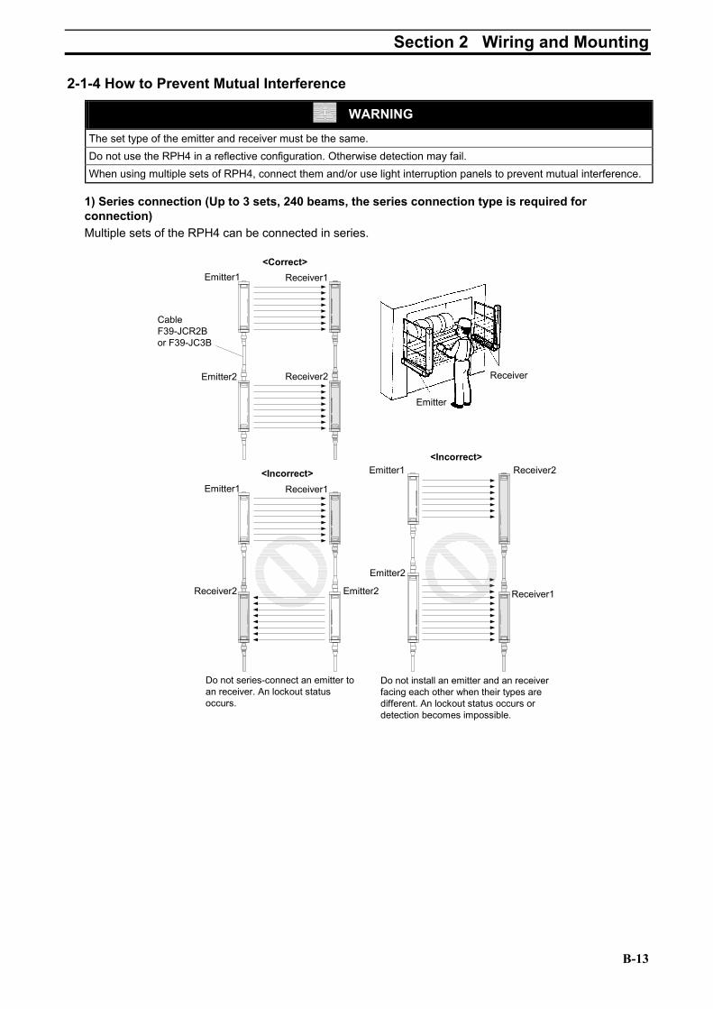
2-1-4 How to Prevent Mutual Interference
WARNING
The set type of the emitter and receiver must be the same. Do not use the RPH4 in a reflective configuration. Otherwise detection may fail. When using multiple sets of RPH4, connect them and/or use light interruption panels to prevent mutual interference.
1) Series connection (Up to 3 sets, 240 beams, the series connection type is required for connection) Multiple sets of the RPH4 can be connected in series.
<Correct>
Emitter1 Receiver1
Emitter2 Receiver2
CableF39-JCR2Bor F39-JC3B
Emitter
Receiver
Do not series-connect an emitter toan receiver. An lockout statusoccurs.
<Incorrect>Emitter1 Receiver1
Receiver2 Emitter2
Do not install an emitter and an receiverfacing each other when their types aredifferent. An lockout status occurs ordetection becomes impossible.
<Incorrect>Emitter1 Receiver2
Emitter2
Receiver1
B-13

Section 2 Wiring and Mounting 2) When not connected When installing two or more light curtains without connecting them to each other due to wiring conditions, considerations must be made to prevent mutual interference. Failure to do so may cause the RPH4 to go into a lockout condition. Installation which may cause mutual interference
<Incorrect>Emitter1 Receiver1 Emitter2 Receiver2 Emitter1 Receiver1
<Incorrect>
Emitter2 Receiver2
Emitter1 Receiver1
Emitter2 Receiver2
<Incorrect>
Installation to prevent mutual interference
• Install so that the two light curtains emit in the opposite directions (staggered). <Correct>
Emitter1Receiver1 Emitter2 Receiver2
Emitter2 Receiver2
<Correct>Emitter1Receiver1
Emitter2Receiver2
Emitter1 Receiver1<Correct>
• Install a light interrupting wall in between sensors.
<Correct>
Emitter1 Receiver1 Emitter2 Receiver2
• Install the light curtains facing away from the one another to eliminate mutual interference.
L
DEmitter Receiver
D
Emitter Receiver
Emitter Receiver
Emitter Receiver6
<Correct>
<Correct>
6
Distance between emitter and receiver (Operating range L)
Minimum installation distance D
0.2 to 3m 0.32m over 3m L x tan6°=
L x 0.105 (m)
B-14

Section 2 Wiring and Mounting
2-2 Dimensional Drawings Dimensions according to the type can be calculated by using the following equations. RPH4 P14 series
Dimension C2 (Protective height): 4 digits in the type name Dimension A = C2 + 86 Dimension B = C2 + 54 Dimension E = C2 – 9 Dimension F: See the right table. Other series Dimension C1 (Protective height) : 4 digits in the type name Dimension A = C1 + 64 Dimension B = C1 + 32 Dimension E = C1 – 37 Dimension F: See the right table.
*1. If value F obtained from the above equation is Side mounting (e.g.: emitter)
1115
9.25
38(4
1.8)
2-Mounting holes
M5 Up-set hexagon bolt
2-Mounting holes
2-Mounting brackets
6.5 dia.
2 8F
16.9
3020
5.5
13.5
9 dia.
4-Mounting holes
2-Mounting holes
282722
30
5.5
Intermediate bracket
F3SN-A P
Protective height (C2)
Number of intermediate
mounting bracket
Dimension F (*1)
to 0620 0 – 0621 to 1125 1 F = B / 2
Protective height (C1)
Number of intermediate
mounting bracket
Dimension F (*1)
to 0640 0 – 0641 to 1280 1 F = B / 2 1281 to 1822 2 F = B / 3
not used, set F to 670 mm or less.
Mounting screw holes
(16)
B A16
27
1
15
45
3211 DE
C2(
Prot
ectiv
e he
ight
)C
1(Pr
otec
tive
heig
ht)
Beam
20.8
17.3
14Connector cap
20
22
FB
4-M5
2-M52-M5
30
-01
B-15

Section 2 Wiring and Mounting Rear mounting (e.g.: emitter)
Mounting screw holes
1115
9.25
38(4
1.8)
2-Mounting holes
M5 Up-set hexagon bolt
2-Mounting holes
2-Mounting brackets
6.5 dia.
2
(16)
8F
B A16
3020
5.5
9 dia.
4-Mounting holes
2-Mounting holes
1
11 DE
C2(
Prot
ectiv
e he
ight
)C
1(Pr
otec
tive
heig
ht)
Beam
14
20
22
FB
4-M5
2-M52-M5
30
30
5.5
Intermesiate bracket
17.3
20.8
Connector cap
15
32
4546.9
13.5
222728
F3SN-A P -01
B-16

Section 2 Wiring and Mounting
2-3 Mounting 2-3-1 How to Mount the Unit
Be sure to have a bend radius of the RPH4 cable of R36 (mm) or more. Eventual failure of the cable may result.
R36
R36
Connector cable
Connector cable80
mm
or m
ore
80m
m o
r mor
e
Shown below with mounting brackets for the emitter and receiver attached. Also shown is how to assemble intermediate mounting bracket and positions where screw holes can be drilled to mount the brackets.
Mounting screw holes
Mounting screw holes
Emitter Receiver
B-17

Section 2 Wiring and Mounting
2-3-2 Dimensional Drawing of the Mounting Bracket Mounting bracket (top and bottom)
13.5
9.25
5.5
1424
209 dia.
6.5 dia.
4-30 deg.
230
45
30
4.3
22 dia.
14.2 dia.
8-R2.15
R2 or less
Material: Carbon steel
Mounting bracket (intermediate) Configuration for rear mounting
2230
116
25 112
10
1727
18
30
1622
Intermediate bracket(2) M4x6 Sensor fixing screw
Intermesiate bracket(3)
M5x8 Bracket fixing screw
332.
3
5.5 5.5
1115
13.7
5
38
2220
42
11
1613
21.2
5
6.5 dia.
9 dia.
Material: Carbon steel
Configuration for side mounting
B-18

Section 2 Wiring and Mounting
Setup procedure when the supplied mounting brackets are used I. Secure the bottom bracket (power connector
side) on a wall or column. II. Secure the intermediate bracket (3) on a wall or
column. [Note]: The arm of receiver is located at the
opposite side of that of the emitter. III. Align the intermediate bracket (2) with the
protrusion of intermediate bracket (1) located on the rear side of the light curtain, and temporarily tighten the supplied screw (M4x6). [Note]: Mount the intermediate bracket (2) so
that its direction is the same as that of the intermediate bracket (3).
IV. Insert the cable connector of the light curtain into the bottom bracket.
V. Move the intermediate bracket (2) until its height is aligned with that of the intermediate bracket (3)(V-a), securely tighten the screw (M4x6)(V-b). [Note]: Be sure to perform this step prior to
mounting the top bracket (cap side). VI. After having aligned the intermediate bracket (2)
with the intermediate bracket (3) in the direction of mounting the light curtain, temporarily tighten the supplied screw (M5x8). Intermediate brackets (2) and (3) are assembled in the following three ways; VI-a, VI-b, VI-c.
VII. Align the top bracket (cap side) with the round hole on the cap, and secure it on a wall or column.
VIII. Insert two supplied screws (M4x8) into both top and bottom brackets, and temporary tighten them (VIII-a, VIII-b). (The figure shown below describes the side mounting.)
IX. Adjust the torsion angle of the light curtain in the point where the five light receiving level indicators are lit.
X. Securely tighten the bottom and top brackets. XI. Then, securely tighten the intermediate brackets. The procedure to mount the light curtain is now
complete.
B-19
Bottom bracket
Intermediate bracket (3)
Intermediate bracket (2)
Top bracket
[Rear mounting] [Side mounting]
Emitting surface
X.
VI-a. VI-b. VI-c.
Side mounting (2) Side mounting (1) Rear mounting
VIII-b. VII. VIII-a.
V-a. V-b. IV.
II. I. III.
XI. IX.

Section 2 Wiring and Mounting
2-4 Wiring
WARNING Do not short-circuit the outputs to +24V. Doing so will cause the output to be always ON. Connect loads between the output and 0V line. (PNP output) Connecting loads between the output and +24V line will reverse the operation mode and the machine will be ON when it is light-interrupted. Always use the two OSSD outputs to configure the safety system. Using only one OSSD of the safety system may result in serious injury when there is an output circuit failure. Do not connect any of the RPH4 lines to a DC power supply with more than 24VDC+10% or to an AC power supply to avoid the danger of electric shock.
(Correct) (Incorrect)
Brown
Green, WhiteBlue
Load
+24V
0V
F3SN-AReceiver
BrownGreen, White
Blue
Load
+24V
0V
F3SN-AReceiver
2-4-1 Power Supply Units
WARNING DC power supply units must satisfy all of the conditions below so that the RPH4 can comply with the applicable standards IEC 61496-1, and UL 508. •
•
•
•
•
•
•
•
The power supply voltage must be within specified ratings (24 VDC ± 10 %). The power supply is connected only to the RPH4 and to the devices related to the electro-sensitive protective function of the RPH4, such as a safety controller and muting sensors, and it has enough rated current for all the devices. The power supply must not be connected to other devices or machines. The power supply uses double or reinforced insulation between the primary and secondary circuits The power supply automatically resets overcurrent protection characteristics (voltage drop). The power supply maintains an output holding time of at least 20 ms. FG (frame ground terminal) must be connected to PE (protective earth) when using a commercially available switching regulator. The power supply must have output characteristics of Class 2 Circuit of Limited Voltage-Current Circuit as defined in UL508 (see “Remark”). The power supply must conform to regulatory requirements and standards, regarding EMC and electrical equipment safety, of the country where the RPH4 is installed and where machinery will be operated. Example: The EMC Directive (industrial environment) and the Low Voltage Directive in EU.
[Remark] The power supply must conform to the following requirement (1) or (2) regarding a secondary circuit, in accordance with UL 508, to avoid a fire.
1) The power supply includes a limited voltage/current circuit supplied by an isolating source like the secondary winding of an isolating type transformer. And, in the limited voltage/current circuit,
– the current available is limited to a value not exceeding 8 A (including the case of short-circuit), or – a secondary fuse or other such secondary circuit protective device used to limit the available current
shall be rated at not more than a value 4.2 amperes (for the power supply voltage of 24VDC) Recommended power supply: S82K (15 W, 30 W, 50 W, 90 W type) made by OMRON.
Certificate of UL Listing (UL508, Class2 Output) and CE Marked (EMC and Low Voltage Directives).
2) The power supply includes a Class 2 circuit supplied by an isolating source that complies with the requirement in the Standard for Class 2 Power Units, UL 1310, or the requirements in the Standard for Class 2 and Class 3 Transformers, UL 1585.
B-20

Section 2 Wiring and Mounting
2-4-2 Wiring Diagram Light curtain only
K1
K2
+24V
(Bro
wn)
+24V
(Bro
wn)
0V (B
lue)
0V (B
lue)
OSS
D1
(Gre
en)
OSS
D2
(Whi
te)
Auxi
liary
(Yel
low
)
EDM
inpu
t (R
ed)
Inte
rlock
sel
ectio
n in
put
(Whi
te)Res
et in
put (
Yello
w)
Test
inpu
t (G
reen
)
(Red
)S1
24VDC
S2
+24V
(Bro
wn)
0V (B
lue)
Inte
rlock
sel
ectio
nin
put (
Whi
te)
Res
et in
put (
Yello
w)
Test
inpu
t (G
reen
)
Ope
nS1
24VDC
S3
Emitter Receiver
Emitter
Wiring for the Auto reset mode
Shie
ld
Shie
ld
Shie
ld
+24V
(Bro
wn)
Auxi
liary
out
put
(Yel
low
)
EDM
inpu
t (R
ed)
Receiver
Wiring when the EDM is not used
OSS
D1
(Gre
en)
S1: External test switchS2: Interlock/Lockout reset switchK1, K2: Relay that control the dangerous zone, etc.K3: Load, PLC, etc. (Used for monitoring)
S3: Lockout reset switch (If the swithch is not necessary, connect betweenthe reset input and +24VDC.)
Note [Note]:If the K3 is notnecessary, only connectthe auxiliary output to theEDM input.
(Red
)
Ope
n
Ope
n
Emitter cableF39-JC A-L
Receiver cableF39-JC A-D
RS-485(B) (Pink)
RS-485(A) (Gray)
Wiring for the Manual reset mode and the EDM function
K3 K1 K2
K3
K1
When the EDM is not necessary 1) If the auxiliary output is in the "Dark-ON output mode",
wire the lines as shown in the figure below to disable theEDM, or
2) Use the F39-MC11 to disable the EDM.
+
+
B-21

Section 2 Wiring and Mounting
Combination with the F3SP-B1P
KM1
KM2
S2
Emitter Receiver
S1: External test switchS2: Interlock/Lockout reset switchKM1, KM2: Relay that control the dangerous zone, etc.K3: Load, PLC, etc. (Used for monitoring)
Emitter cableF39-JC B-L
Receiver cableF39-JC B-D
A1
T31PE T32 P1 14 24 34 42
41332313X1H1J1L1H1
A2
K1 K2
K1
K2
OSSD1 OSSD2
Interlockselection Reset
EDM Auxiliary
Test
S1
24VDC
KM1 KM2
F3SP-B1P
S3
X1H1J1L1H1
Interlockselection ResetTest
S1
Wiring for the Auto reset mode
S3: Lockout reset switch (If the swithch is not necessary, connect between X1 and H1.)
K3
[Note]: If the EDM is not necessary, short-circuit T31 and T32.
Wiring for the Manual reset mode and the EDM function
+
B-22

Section 2 Wiring and Mounting
2-4-3 Wiring Procedures 1. Connect the emitter cable (F39-JC -L optional, gray color outer jacket) to the emitter. 2. Connect the receiver cable (F39-JC -D optional, black color outer jacket) to the receiver. 3. Connect the 0V line of the power supply directly to protective earth (PE). [Note]: Be sure to wire correctly. Failure to do so may damage the RPH4. Confirm the color of cables and
outer jackets (emitter: gray, receiver: black). Matching colors prevents incorrect wiring. Connector (Main Unit End)
Signal Name Front View Pin No.
Receiver Emitter Wire Color of Optional Cable
1 OSSD 2 Interlock selection input (INTERLOCK)
White
2 +24 VDC (24VDC) +24 VDC (24VDC) Brown
3 OSSD 1 Test input Green
4 Auxiliary output Reset input (RESET) Yellow
5 RS-485 (A) RS-485 (A) Gray
6 RS-485 (B) RS-485 (B) Pink
7 0 V 0 V Blue
17
28
6
5
3 4
8 EDM input N.C. Red
Single-ended connector cable (F39–JC A Optional)
40.7 L
14.9
dia
.
M12 Waterproof connector Vinil insulated round cable 6.6mm dia.8cores(4twisted pairs) (conductor cross sectional area: 0.3mm2
/ insulationoutside diameter: 1.15mm dia.)
Unit: mm
Type (set name) For Emitter For Receiver L F39-JC3A F39-JC3A-L F39-JC3A-D 3000 F39-JC7A F39-JC7A-L F39-JC7A-D 7000 F39-JC10A F39-JC10A-L F39-JC10A-D 10000 F39-JC15A F39-JC15A-L
Gray outer jacket color
F39-JC15A-D
Black outer jacket color
15000
B-23

Section 2 Wiring and Mounting Double-ended connector cable for Series Connection and Connection to the F3SP-B1P (F39–JC B Optional)
14.9
dia
.
M12 Waterproof connector
40.7 L 44.7
M12 Waterproof connector
Vinil insulated round cable 6.6mm dia.8cores(4twisted pairs) (conductor cross sectional area: 0.3mm2
/ insulationoutside diameter: 1.15mm dia.)
14.9
dia.
Unit: mm
Type (set name) For Emitter For Receiver L
F39-JCR2B F39-JCR2B-L F39-JCR2B-D 200
F39-JC3B F39-JC3B-L F39-JC3B-D 3000
F39-JC7B F39-JC7B-L F39-JC7B-D 7000 Note
F39-JC10B F39-JC10B-L F39-JC10B-D 10000 Note
F39-JC15B F39-JC15B-L
Gray outer jacket color
F39-JC15B-D
Black outer jacket color
15000 Note
[Note]: Do not use for series connection.
2-4-4 Adjustment Procedures [Procedures] 1. Ensure the following points. • The optical surfaces of the emitter and receiver are clean. • There should be no light-interrupting objects in the RPH4 detection zone. 2. Adjust the beams of the emitter. Adjust the torsion angle of the emitter while monitoring the light intensity level indicator and locate the emitter in the point where the ON-state indicator (lit: green) is lit. 3. Adjust the receiver. Adjust the torsion angle of the receiver while monitoring the light intensity level indicator and locate the receiver in the point where the ON-state indicator (lit: green) is lit. 4. Confirm all the light intensity level indicators are lit. 5. When the above adjustments have been completed, tighten all brackets and mounting screws while being careful not to change the beam adjustment for the light curtain.
Mounting bracket type Screw designation and length (mm) Tightening torque
Mounting bracket (Top and bottom) M4×8 1.2 N·m
M4×6 1.2 N·m Mounting bracket (Intermediate) M5×8 2.0 N·m
6. If all of the light intensity level indicators are not lit through the above angle adjustment of the receiver, check for parallelism between the emitter mounting surface and the receiver mounting surface and also check if the emitter and receiver are mounted to the same height.
B-24

Section 2 Wiring and Mounting
2-5 Check List A person in charge should check the following check boxes.
Check the following items to make sure the installation is correct. 1. Machine structure does not hinder stop and other safety functions. 2. Intrusion into a hazardous part of the machine is not possible without passing through the RPH4 detection zone. 3. Protective structure allows the RPH4 to detect an operator when he/she works in the hazardous area. 4. The switch to reset the interlock condition has to be installed so that the entire hazardous area is visibly free and the switch can not be operated from within the hazardous area. 5. The safety distance has been calculated. Calculated distance: S = ( ) mm 6. The actual safety distance is greater than the calculated distance. Actual distance = ( ) mm 7. Reflective surfaces are not installed in prohibited areas.
Check the following items to make sure wiring is correct before turning ON power. 1. The power supply is connected only to the RPH4 and to the devices related to the electro-sensitive protective function of the RPH4, such as a safety controller and muting sensors, and it has enough rated current for all the devices. 2. The power supply unit is a 24 VDC unit that conforms to the EMC Directive, Low-voltage Directive, and output holding specifications. 3. The polarity of the power supply connection is not reversed. 4. The emitter cable is properly connected to the emitter and the receiver cable is properly connected to the receiver. 5. Double insulation is used between I/O lines and the hazard potential (commercial power supplies, etc.). 6. Outputs are not shorted to the +24V line. 7. Loads are not connected to the +24V line. 8. No lines are connected to a commercial supply line. 9. When two or more units are used, they are connected or installed properly to prevent mutual interference. Check the RPH4 operations with the machine stopped. 1. A test rod is not deformed. (note 1) 2. Nothing is present in the detection zone. The power indicator, the ON-state indicator and all of the light intensity level indicators are lit within one second after the RPH4 is turned ON. 3. A test rod can be detected at any position in the detection zone. In other words, all the light intensity level indicators go off and the OFF-state indicator will remain lit as long as the test rod is present in the detection zone. Guide the test rod through detection zone as shown in the figure. (Note2)
[Note1]: The size of the detection capability varies depending on the light curtain type and the floating blanking setting. Perform inspection using a test rod with a proper diameter. (Test rod is not supplied with the RPH4 P70 series.) The diameter of the supplied test rod is not suitable for the inspection when the floating blanking function is used. Prepare the test rod of the proper diameter. (Refer to “1-2-7 Floating Blanking function”).
Start Stop
[Note2]: When fixed blanking is used, confirm that all entries to the disabled detection zone are blocked by protective structures and the test rod can be detected at any position in the detection zone.
B-25

Section 2 Wiring and Mounting 4. In case the external test function is used: When the test input line is short-circuited to the 9DC to24V line, the OFF-state indicator is lit. 5. In case the EDM function is used: When the light curtain is interrupted and the EDM input line becomes open, the light curtain enters the lockout condition. 6. In case the start interlock function is used: Even if the light curtain receives light after turning power ON, the OFF-state indicator remains lit. If the reset switch is input, the ON-state indicator is lit. 7. In case the restart interlock function is used: When the light curtain is interrupted, then go back to the light receiving condition, the OFF-state indicator remains lit. If the reset switch is input, the ON-state indicator is lit.
Operate the machine and check to see if a hazardous part stops under the conditions below. 1. The hazardous part immediately stops when a test rod is intruded in the detection zone at 3 points: Directly in front of the emitter, Directly in front of the receiver, Midway between the emitter and receiver. (Use correct test rod as described in Step 3.) 2. The hazardous part remains stopped as long as the test rod is present in the detection zone. 3. The hazardous part stops when the RPH4 power supply is turned OFF. 4. The overall measured machine response time is less than the calculated time.
B-26

Section 3 I/O Circuit
Section 3 I/O Circuit
Emitter maincircuit
7
Display
Display
Receiver maincircuit 2
2
8
1
4
Receivermain circuit 1
8
7
5 6
5 6
7
3
4
+24V2
3
1
4
Brown
GreenTest input (*1)
WhiteInterlock selection input(*2)
Reset input (*2)Yellow
Blue
Brown
External relay monitor input (*2)Red
Green
Control output 1
Green
Control output2
Auxiliary output
Blue
Load
Load
0V
Load
RS-485(B)
PinkGrey
Grey Pink
RS-485(A)
Ext. indicatoroutput
0V
Ext. indicatoroutput
0V
7
Load
Load
Yellow
*1. Open: Normal light emission, Short to the +24VDC: stops light emission *2. Refer to 2-4-2 Wiring Diagram *3. The section encircled with the dashed line is applied for RPH4 P -01 only.
[Note]: The numbers in indicate pin numbers of the connectors. The numbers in indicate pin numbers of the series connection connectors.
B-27

Section 3 I/O Circuit Output Waveform of the OSSD outputs The OSSD outputs will be OFF as shown in the following figure in order to perform the OSSD circuit self-test when the light curtain is in the ON-state. The OSSD circuit diagnosis is correct when this OFF signal is fed back. If the output signal does not contain an OFF signal, the receiver determines that there is an output circuit or wiring failure and goes into the lockout condition. The number of OFF signals depends on the number of light curtains connected in series. (See the table below.)
Approx. 25 µs
ON
OFFOSSD
Response time
160 ~ 200 µs
OFF signal
No. of light
curtains connected in series
No. of OFF signals within the response time
No series connection
1
2 light curtains 2 3 light curtains 3
curtains connected in series
No. of ON signals within the response time
No series connection
1
2 light curtains 2 3 light curtains 3
In the same way, the OSSD outputs will be ON as shown in the following figure, to perform the OSSD circuit self-test when the light curtain is in the OFF-state. Check the input response time of a machine connected to the RPH4 carefully to ensure the machine will not malfunction due to the OFF signal.
ON
OFFOSSD
Response time
Approx. 130 µs
ON signal
No. of light
B-28

Section 4 Application
Section 4 Application This section shows examples of a motor control system that combines an RPH4. These are category 4 systems (EN954-1 provision). Application 1
KM1
KM2
S2
Emitter Receiver
S1: External test switchS2: Interlock/Lockout reset switchKM1, KM2: Magnet contactor (LP1D)KM3: Solid-state contactor (G3J)M: 3-phase motorE1: 24 VDC Power Supply (S82K)PLC: Programmable Logic Controller (Used for monitoring. This is not a part of a saety system.)
A1
T31PE T32
P1
14 24 34 42
41332313X1H1J1L1H1
A2
K1 K2
K1
K2
OSSD1 OSSD2
Interlockselection Reset
EDM
AuxiliaryTest
S1
E1
KM1 KM2
F3SP-B1P
+
M
OUT
PLC
KM1
KM2
- Combination with the contorl unit F3SP-B1P- Manual reset mode- Using the EDM function
KM1, KM2 N.C.contact
IN1 IN2
PLC input 1
Light receptionLight interrupted
Ext. test SW (S1)
Reset SW (S2)
OSSDs
K1, K2 N.O.contact
KM1, KM2 N.O.contact
K1, K2 N.C.contact
PLC input 2
PLC output
KM3
Depends on the operationmode of the auxiliary output
Application 2
KM1
KM2
+24V
(Bro
wn)
+24V
(Bro
wn)
0V (B
lue)
0V (B
lue)
OSS
D1
(Gre
en)
OSS
D2
(Whi
te)
Auxi
liary
(Yel
low
)
EDM
inpu
t (R
ed)
Inte
rlock
sel
ectio
n in
put
(Whi
te)Res
et in
put (
Yello
w)
Test
inpu
t (G
reen
)
(Red
)S1
E1
S2
Emitter Receiver
Shie
ld
Shie
ld
S1: External test switchS2: Interlock/Lockout reset switchKM1, KM2: Safety relay with the forcibly guided contacs (G7SA) orMagnet contactor (LP1D)KM3: Solid-state contactor (G3J)M: 3-phase motorE1: 24 VDC Power supply (S82K)PLC: Programmable Logic Controller (Used for monitoring. This is not a part of a safety system)
Ope
n
RS-485(B) (Pink)
RS-485(A) (Gray)
+
M
KM1
KM2
- Manual reset mode- Using the EDM function
KM1, KM2 N.C.contact
Light receptionLight interrupted
Ext. test SW (S1)
Reset SW (S2)
OSSDs
KM1, KM2 N.O.contact
PLC input (*)
PLC outputKM1 KM2
OUT
PLC
IN
* : The output operation mode of the auxiliary output isthe Dark-ON output mode.
KM3
B-29

Section 4 Application Application 3
S1: External test switchS2: Reset switchS3: Emergency stop switch (A165E, or A22E)KM1, KM2: Magnet contactor (LP1D)KM3: Solid-state contactor (G3J)M: 3-phase motorE1: 24 VDC Power Supply (S82K)PLC: Programmable Logic Controller (Used for monitoring. This is not a part of a saety system.)
M
OUT
PLC
KM1
KM2
- Combination with the safety relay unit G9SA-301- Setting of the F3SN-A Auto reset mode Disabled the EDM function by the F39-MC11- Setting of the safety relay unit Manual reset mode Using feedback loop- Using a emergency stop switch
KM1, KM2 N.C.contact
IN1 IN2
PLC input 1
Light receptionLight interrupted
Ext. test SW (S1)
Reset SW (S2)
OSSDs
K1, K2 N.O.contact
KM1, KM2 N.O.contact
K1, K2 N.C.contact
PLC input 2
PLC output
KM3
A1
T23PE 14 24 34 42
41332313X1Y1T11A2
KM1 KM2G9SA-301
KM1
KM2
T12
K1K1
K2
K1
T21
‚r 2
+24V
(Bro
wn)
+24V
(Bro
wn)
0V (B
lue)
0V (B
lue)
OSS
D1
(Gre
en)
OSS
D2
(Whi
te)
Auxi
liary
(Yel
low
)
EDM
inpu
t (R
ed)
Inte
rlock
sel
ectio
nin
put (
Whi
te)
Res
et in
put (
Yello
w)
Test
inpu
t (G
reen
)
(Red
)S1
E1
Emitter Receiver
Shie
ld
Shie
ldOpe
n
RS-485(B) (Pink)
RS-485(A) (Gray)
+
6
a K2
K2b
ControlCircuit
T22 A B
ab
25
Ope
n
134
123456
JP
11
12
21
22
S3
Ope
n Emergency stopSW (S3)
Depends on the operationmode of the auxiliary output
B-30

Section 5 Maintenance
Section 5 Maintenance
WARNING Do not use the RPH4 until the following inspections are completed. Failure to do so may result in loss of life or serious injury. Do not disassemble, repair or modify the RPH4.
[Note]: For safety, be sure to record and store inspection results.
Make sure you are thoroughly familiar with the RPH4 and the machine prior to conduction an inspection. If the installer, design technician and user are different individuals, make sure the user has adequate guidelines for performing maintenance.
5-1 Daily Inspections
Be sure to inspect the following items at the start of work or after a shift change. 1. No instruction paths into dangerous machine parts expect through the RPH4 detection zone. 2. Some part of the operator’s body remains in the RPH4 detection zone at all times while working in dangerous machine parts. 3. The actual safety distance is greater than the calculated distance. 4. No dirt or scratches on the optical surface or the spatter protection cover (the F39-HN, optional) of the RPH4. 5. A detected material for inspection is not deformed. 6. Confirm nothing is present in the detection zone, then turn on the power of RPH4. When the start interlock is not used: The power indicator and the ON-state indicator are lit within one second after turning ON the power. When the start interlock is used: The power indicator and the OFF-state indicator are lit within one second after turning ON the power. 7. The test rod can be detected when guiding it through detection zone as shown in the figure. In other words, the OFF-state indicator will be lit when the test rod is inserted into the detection zone.
[Note]: Perform inspection with the proper size test rod in accordance to the light curtain type and the floating blanking setting.
Start Stop
Operate the machine and check to see if the dangerous part stops under the conditions below. 8. The dangerous part moves when there is nothing in the detection zone. 9. The dangerous part stops immediately when the test rod is inserted into the detection zone directly in front of the emitter, directly in front of the receiver and midway between the emitter and receiver. (Use the correct test rod) 10. The dangerous part remains stopped as long as the test rod is present in the detection zone. 11. The dangerous part remains stopped when the RPH4 power supply is turned OFF.
B-31

Section 5 Maintenance
5-2 Inspections Every Six Months Inspect the following items every six months or when a machine setting is changed. 1. Machine structure does not hinder stop and other safety functions. 2. There is no machine modification or connection change that will adversely affect the control system. 3. RPH4 outputs are correctly wired to the machine. 4. The actual overall response time of the machine is less than the calculated response time. 5. The control relay and/or contactor are good condition. 6. The screws for brackets are secured tightly. 7. There is no interference light.
B-32

Section 6 Troubleshooting
Section 6 Troubleshooting 6-1 Lockout condition
When the light curtain enters the lockout condition, the error content will be displayed by a flashing pattern of the Error mode indicator. Devise a countermeasure in accordance with the following table.
[Note]: For some error conditions, either only the emitter or receiver will blink. Error mode indicator
ause emedy
A B C
Wiring error for interlock function setting
1) The reset input line and the interlock selection input line are not wired correctly. 2) The interlock selection input line became open or shorted during power-on.
1)-2) Confirms the wiring for the auto reset mode or the manual reset mode.
A B C
Error of the relay monitoring function
1) One of the external relay contacts is welded. 2) The EDM input line is not wired correctly to the external relays. 3) The setting value of relay monitoring time is lower than the relay response time. 4) In the case of connecting the EDM input line to the auxiliary output line in order to make the EDM function inactive, lines are open or shorted to the 0 V line.
1) Replace the relay. 2) Check connection of the relay monitoring input line. 3) Replace with a relay of proper release time, or change the setting value of the relay monitoring time by the F39-MC11. 4) Check the EDM input line and the auxiliary output line for error. Then, confirm that the operation mode for the auxiliary output is in the Dark-ON output mode.
A B C
RS-485 communication line error
1) The RS-485 communication line is open or shorted to the other I/O line. 2) Communication error by noises. 3) When the light curtains are connected in series, the connector of the series connection cable is disconnected. 4) Failure of the CPU.
1) Check connection of the RS-485 lines. 2) Check noise environment around the RS-485 communication lines. 3) Check the cable connection between the light curtains connected in series. 4) Replace the light curtain
A B C
OSSD error 1) OSSD outputs are shorted together 2) At least one OSSD output is shorted to the +24V line, 0V line, or the other I/O line. 3) Failure of OSSD output circuit
1)-2) Rewire the OSSD outputs correctly. 3) Replace the receiver.
A B C
Error by interference light
1) Interference light is received. 2) The emission light of the other photoelectric light curtain or light curtain is received.
1)-2) Interrupt the interference light. (Refer to 2-1-4)
A B C
Incorrect configuration on the light curtain connection
1) The type of the receiver is different from the type of the emitter. (e.g. the number of beams is different.) 2) The number of the receiver connected in series is different from that of the emitter.
1)-2) Correct the type or the number of the light curtain connected in series.
A B C
Error by noises or Destruction of the light curtain
1) Influenced by significant noise. 2) Internal hardware failure of the receiver or the emitter.
1) Check noise environment around the light curtain. 2) Replace the receiver or the emitter.
C R
Flashing Not lit
B-33

Section 6 Troubleshooting
6-2 Other trouble In case the light curtain does not work, even if the lockout indicator and the error mode indicator are not flashing, devise a countermeasure in accordance with the following table.
Phenomenon Cause Remedy
The light intensity level indicator does not lit although any beams are not interrupted.
1) RS-485 communication lines are not connected. 2) RS-485 communication lines are influenced by significant noise. 3) Auxiliary output is connected to + 24V line.
1) Reconnect the RS-485 line correctly. 2) Check noise environment around the RS-485 lines. 3) Open the auxiliary output line, or connect to the 0V line via a load.
B-34

Section 7 Optional Accessory
Section 7 Optional Accessory Single-ended connector cable (For emitter and for receiver, set of 2)
Appearance Type Length Specification F39-JC3A 3m F39-JC7A 7m F39-JC10A 10m
F39-JC15A 15m
M12 connector (8pins)
Double-ended connector cable (For emitter and for receiver, set of 2)
Appearance Type Length Specification F39-JCR5B 0.2m F39-JC3B 3m F39-JC7B 7m F39-JC10B 10m
F39-JC15B 15m
M12 connector (8pins)
Control unit
Appearance Type Output
F3SP-B1P Relay (3NO + 1NC)
Setting console
Appearance Type Accessory
F39-MC11 Branching connector, Connector cap, Cable
External indicator *Series connection type is required for connection
Appearance Type Applicable light curtain
Indicator color
Specification
F39-A01PR-L Red F39-A01PG-L
Emitter Green
F39-A01PR-D Red F39-A01PG-D
Receiver Green
M12 connector
30 dia.
85.8
94.3
Lighting part
M12 Connector
9.2
B-35

Section 7 Optional Accessory Spatter protection cover (for both emitter and receiver, set of 2)
Appearance Type *1 Applicable sensor F39-HN -14
RPH4 P14 / P14-01
F39-HN -25 RPH4 P25 / P25-01 RPH4 P40 / P40-01 RPH4 P70 / P70-01
*1. The same 4-digit numbers as the protective heights ( in the light curtain type names) are substituted by in the type names.
*2. The operating range of the light curtain will decrease by 10% when using the spatter protection cover.
[Spatter protection cover]
32
L10
*L is as follows: F39-HN -14 L = mm F39-HN -25 L = - 22 mm
Material: PC (transparent area) ABS (non-transparent area)
[Fixing bracket]
14
37.3
9.9
[Mounting dimension]
32.6
37.3
B-36
Material: Stainless steel

Section 8 Referenced standards
Section 8 Referenced standards International Standards - IEC61496-1 Safety of Machinery: Electro-sensitive Protective Equipment – Part 1: General Requirements
and Tests - IEC61496-2 Safety of Machinery: Electro-sensitive Protective Equipment – Part 2: Particular
Requirements for Equipment Using Active Opto-electronic Protective Devices European Standards - EN61496-1 Safety of Machinery: Electro-sensitive Protective Equipment – Part 1: General Requirements
and Tests - EN954-1 Safety of Machinery: Safety-related Parts of Control Systems – Part 1: General Principles for
Design - EN415-4 Palletizers and depalletizers - prEN691 Woodworking machines - EN692 Mechanical presses - prEN693 Hydraulic presses U.S. Federal regulations - OSHA 29 CFR 1910.212 General Requirements of All Machines - OSHA 29 CFR 1910.217 Mechanical Power Presses U.S. Standards - ANSI B11.1 Mechanical Power Presses - ANSI B11.2 Hydraulic Power Presses - ANSI B11.3 Power Press Brakes - ANSI B11.4 Shears - ANSI B11.5 Iron Workers - ANSI B11.6 Lathes - ANSI B11.7 Cold Headers and Cold Formers - ANSI B11.8 Drilling, Milling, and Boring Machines - ANSI B11.9 Grinding Machines - ANSI B11.10 Metal Sawing Machines - ANSI B11.11 Gear Cutting machines - ANSI B11.12 Roll Forming and Roll Bending Machines - ANSI B11.13 Single- and Multiple-Spindle Automatic Bar and Chucking Machines - ANSI B11.14 Coil Slitting Machines/Systems - ANSI B11.15 Pipe, Tube, and Shape Bending Machines - ANSI B11.16 Metal Powder Compacting Presses - ANSI B11.17 Horizontal Extrusion Presses - ANSI B11.18 Machinery and Machine Systems for the Processing of Coiled Strip, Sheet, and Standards - ANSI B11.19 Performance Criteria for the Design, Construction, Care, and Operation of Safeguarding
when Referenced by the Other B11 Machine Tool Safety Standards - ANSI/RIA 15.06 Safety Requirements for Industrial Robots and Robot Systems - UL1998 Safety-related Software
B-37