beagle board manual rev. c4
TRANSCRIPT

8/2/2019 Beagle Board Manual Rev. C4
http://slidepdf.com/reader/full/beagle-board-manual-rev-c4 1/180
REF: BB_SRM BeagleBoard SystemReference Manual
Revision C4
Page 1 of 180
BeagleBoard
System Reference Manual
Rev C4Revision 0.0
December 15, 2009
C4

8/2/2019 Beagle Board Manual Rev. C4
http://slidepdf.com/reader/full/beagle-board-manual-rev-c4 2/180
REF: BB_SRM BeagleBoard SystemReference Manual
Revision C4
Page 2 of 180
THIS DOCUMENT
This work is licensed under the Creative Commons Attribution-Share Alike 3.0 Unported License. To view a copy of this license, visit http://creativecommons.org/licenses/by-
sa/3.0/ or send a letter to Creative Commons, 171 Second Street, Suite 300, San Francisco, California, 94105, USA.
All derivative works are to be attributed to Gerald Coley of BeagleBoard.org.
For more information, see http://creativecommons.org/license/results-
one?license_code=by-sa
For any questions, concerns, or issues submit them to [email protected]
BEAGLEBOARD DESIGN
These design materials referred to in this document are *NOT SUPPORTED* and DO
NOT constitute a reference design. Only “community” support is allowed via resourcesat BeagleBoard.org/discuss.
THERE IS NO WARRANTY FOR THE DESIGN MATERIALS, TO THE EXTENTPERMITTED BY APPLICABLE LAW. EXCEPT WHEN OTHERWISE STATED IN
WRITING THE COPYRIGHT HOLDERS AND/OR OTHER PARTIES PROVIDETHE DESIGN MATERIALS “AS IS” WITHOUT WARRANTY OF ANY KIND,EITHER EXPRESSED OR IMPLIED, INCLUDING, BUT NOT LIMITED TO, THEIMPLIED WARRANTIES OF MERCHANTABILITY AND FITNESS FOR APARTICULAR PURPOSE. THE ENTIRE RISK AS TO THE QUALITY ANDPERFORMANCE OF THE DESIGN MATERIALS IS WITH YOU. SHOULD THEDESIGN MATERIALS PROVE DEFECTIVE, YOU ASSUME THE COST OF ALL NECESSARY SERVICING, REPAIR OR CORRECTION.
We mean it; these design materials may be totally unsuitable for any purposes.

8/2/2019 Beagle Board Manual Rev. C4
http://slidepdf.com/reader/full/beagle-board-manual-rev-c4 3/180
REF: BB_SRM BeagleBoard SystemReference Manual
Revision C4
Page 3 of 180
BeagleBoard.org provides the enclosed product(s) under the following conditions:
This evaluation board/kit is intended for use for ENGINEERING DEVELOPMENT, DEMONSTRATION, OREVALUATION PURPOSES ONLY and is not considered by BeagleBoard.org to be a finished end-product
fit for general consumer use. Persons handling the product(s) must have electronics training and observegood engineering practice standards. As such, the goods being provided are not intended to be complete interms of required design-, marketing-, and/or manufacturing-related protective considerations, includingproduct safety and environmental measures typically found in end products that incorporate suchsemiconductor components or circuit boards. This evaluation board/kit does not fall within the scope of theEuropean Union directives regarding electromagnetic compatibility, restricted substances (RoHS), recycling(WEEE), FCC, CE or UL, and therefore may not meet the technical requirements of these directives or otherrelated directives.
Should this evaluation board/kit not meet the specifications indicated in the User’s Guide, the board/kit maybe returned within 30 days from the date of delivery for a full refund. THE FOREGOING WARRANTY ISTHE EXCLUSIVE WARRANTY MADE BY SELLER TO BUYER AND IS IN LIEU OF ALL OTHER
WARRANTIES, EXPRESSED, IMPLIED, OR STATUTORY, INCLUDING ANY WARRANTY OFMERCHANTABILITY OR FITNESS FOR ANY PARTICULAR PURPOSE.
The user assumes all responsibility and liability for proper and safe handling of the goods. Further, the userindemnifies BeagleBoard.org from all claims arising from the handling or use of the goods. Due to the openconstruction of the product, it is the user’s responsibility to take any and all appropriate precautions withregard to electrostatic discharge.
EXCEPT TO THE EXTENT OF THE INDEMNITY SET FORTH ABOVE, NEITHER PARTY SHALL BELIABLE TO THE OTHER FOR ANY INDIRECT, SPECIAL, INCIDENTAL, OR CONSEQUENTIALDAMAGES.
BeagleBoard.org currently deals with a variety of customers for products, and therefore our arrangementwith the user is not exclusive. BeagleBoard.org assumes no liability for applications assistance,customer product design, software performance, or infringement of patents or services describedherein.
Please read the User’s Guide and, specifically, the Warnings and Restrictions notice in the User’s Guideprior to handling the product. This notice contains important safety information about temperatures andvoltages. For additional information on BeagleBoard.org environmental and/or safety programs, pleasecontact visit BeagleBoard.org.
No license is granted under any patent right or other intellectual property right of BeagleBoard.org coveringor relating to any machine, process, or combination in which such BeagleBoard.org products or services
might be or are used.
Mailing Address:
BeagleBoard.org675 North Glenville #195Richardson, TX 75081

8/2/2019 Beagle Board Manual Rev. C4
http://slidepdf.com/reader/full/beagle-board-manual-rev-c4 4/180
REF: BB_SRM BeagleBoard SystemReference Manual
Revision C4
Page 4 of 180
WARRANTY: The BeagleBoard is warranted against defects in materials and workmanship for a period of 90 days from purchase. This warranty does not cover any problems occurring as a result of improper use, modifications, exposure to water, excessive voltages, abuse, or accidents. All boards will be returned via standard mail if an issue is found. If no issue is found or express return is needed, the customer will pay all shipping costs .
Before returning the board, please visit BeagleBoard.org/support
Please refer to sections 12 and 13 of this document for the board checkout procedures andtroubleshooting guides.
To return a defective board, please request an RMA at http://beagleboard.org/support/rma .
8/2/2019 Beagle Board Manual Rev. C4
http://slidepdf.com/reader/full/beagle-board-manual-rev-c4 5/180
REF: BB_SRM BeagleBoard SystemReference Manual
Revision C4
Page 5 of 180
Table of Contents
FIGURES.......................................................................................................................................................9
TABLES.......................................................................................................................................................11
1.0 INTRODUCTION.........................................................................................................................13
2.0 CHANGE HISTORY....................................................................................................................14
2.1 CHANGE HISTORY.......................................................................................................................14 2.2 R EVISION C3 VS. C4 ...................................................................................................................14
3.0 DEFINITIONS AND REFERENCES.........................................................................................15
3.1 DEFINITIONS ...............................................................................................................................15
4.0 BEAGLEBOARD OVERVIEW..................................................................................................15
4.1 BEAGLEBOARD USAGE SCENARIOS ............................................................................................15
5.0 BEAGLEBOARD SPECIFICATION.........................................................................................17
5.1 BEAGLEBOARD FEATURES..........................................................................................................17 5.2 OMAP PROCESSOR .....................................................................................................................18 5.3 MEMORY.....................................................................................................................................18 5.4 POWER MANAGEMENT................................................................................................................18 5.5 HS USB 2.0 OTG PORT..............................................................................................................19 5.6 HS USB 2.0 HOST PORT .............................................................................................................19 5.7 STEREO AUDIO OUTPUT CONNECTOR .........................................................................................20 5.8 STEREO AUDIO I N CONNECTOR ..................................................................................................20 5.9 S-VIDEO CONNECTOR .................................................................................................................20 5.10 DVI-D CONNECTOR ....................................................................................................................20 5.11 LCD HEADER .............................................................................................................................20 5.12 SD/MMC 6 IN 1 CONNECTOR .....................................................................................................21 5.13 R ESET BUTTON ...........................................................................................................................21 5.14 USER /BOOT BUTTON ..................................................................................................................21 5.15 I NDICATORS ................................................................................................................................22 5.16 POWER CONNECTOR ...................................................................................................................22 5.17 JTAG CONNECTOR .....................................................................................................................23 5.18 RS232 HEADER ..........................................................................................................................23 5.19 EXPANSION HEADER ...................................................................................................................23 5.20 BEAGLEBOARD MECHANICAL SPECIFICATIONS ..........................................................................23 5.21 ELECTRICAL SPECIFICATIONS .....................................................................................................24
6.0 PRODUCT CONTENTS..............................................................................................................26
6.1 BEAGLEBOARD I N THE BOX R EV C4 ..........................................................................................26 6.2 SOFTWARE ON THE BEAGLEBOARD ............................................................................................27 6.3 R EPAIR ........................................................................................................................................27
7.0 BEAGLEBOARD HOOKUP.......................................................................................................28
7.1 CONNECTING USB OTG.............................................................................................................28 7.2 CONNECTING USB HOST ............................................................................................................29 7.3 CONNECTING OPTIONAL POWER .................................................................................................30 7.4 CONNECTING JTAG....................................................................................................................31 7.5 CONNECTING SERIAL CABLE ......................................................................................................32 7.6 CONNECTING S-VIDEO................................................................................................................33 7.7 CONNECTING DVI-D CABLE.......................................................................................................34
8/2/2019 Beagle Board Manual Rev. C4
http://slidepdf.com/reader/full/beagle-board-manual-rev-c4 6/180
REF: BB_SRM BeagleBoard SystemReference Manual
Revision C4
Page 6 of 180
7.8 CONNECTING STEREO OUT CABLE..............................................................................................35 7.9 CONNECTING STEREO I N CABLE .................................................................................................36 7.10 I NDICATOR LOCATIONS...............................................................................................................37 7.11 BUTTON LOCATIONS ...................................................................................................................38 7.12 SD/MMC CONNECTION ..............................................................................................................39 7.13 LCD CONNECTION ......................................................................................................................40
8.0 BEAGLEBOARD SYSTEM ARCHITECTURE AND DESIGN.............................................41
8.1 SYSTEM BLOCK DIAGRAM ..........................................................................................................41 8.2 I NPUT POWER ..............................................................................................................................44
8.2.1 USB DC Source .....................................................................................................................45 8.2.2 Wall Supply Source ...............................................................................................................45 8.2.3 DC Source Control................................................................................................................45 8.2.4 3.3V Supply............................................................................................................................46 8.2.5 Meter Current Measurement .................................................................................................46 8.2.6 Processor Current Measurement...........................................................................................46
8.3 POWER CONDITIONING ...............................................................................................................47 8.4 TPS65950 R ESET AND POWER MANAGEMENT ...........................................................................48
8.4.1 Main Core Voltages...............................................................................................................49
8.4.2 Main DC Input.......................................................................................................................49 8.4.3 OMAP3530 I2C Control........................................................................................................49 8.4.4 VIO_1V8................................................................................................................................49 8.4.5 Main Core Voltages Smart Reflex .........................................................................................51 8.4.6 VOCORE_1V3.......................................................................................................................51 8.4.7 VDD2.....................................................................................................................................51
8.5 PERIPHERAL VOLTAGES ..............................................................................................................52 8.5.1 VDD_PLL2............................................................................................................................52 8.5.2 VDD_PLL1............................................................................................................................52 8.5.3 VDAC_1V8............................................................................................................................54 8.5.4 VDD_SIM..............................................................................................................................54 8.5.5 VMMC1.................................................................................................................................54 8.5.6 VAUX2...................................................................................................................................54 8.5.7
Boot Configuration................................................................................................................54
8.5.8 RTC Backup Battery..............................................................................................................55 8.5.9 Power Sequencing .................................................................................................................56 8.5.10 Reset Signals.....................................................................................................................57 8.5.11 mSecure Signal.................................................................................................................58
8.6 OMAP3530 PROCESSOR .............................................................................................................59 8.6.1 Overview................................................................................................................................59 8.6.2 SDRAM Bus...........................................................................................................................60 8.6.3 GPMC Bus.............................................................................................................................60 8.6.4 DSS Bus.................................................................................................................................61 8.6.5 McBSP2.................................................................................................................................61 8.6.6 McBSP1.................................................................................................................................61 8.6.7 McBSP3.................................................................................................................................62 8.6.8 Pin Muxing............................................................................................................................62 8.6.9 GPIO Mapping......................................................................................................................64 8.6.10 Interrupt Mapping ............................................................................................................64
8.7 POP MEMORY DEVICE ...............................................................................................................65 8.8 SYSTEM CLOCKS.........................................................................................................................65
8.8.1 32KHz Clock .........................................................................................................................65 8.8.2 26MHz Clock.........................................................................................................................66 8.8.3 McBSP_CLKS .......................................................................................................................66
8.9 USB OTG PORT..........................................................................................................................67 8.9.1 USB OTG Overview ..............................................................................................................67

8/2/2019 Beagle Board Manual Rev. C4
http://slidepdf.com/reader/full/beagle-board-manual-rev-c4 7/180
REF: BB_SRM BeagleBoard SystemReference Manual
Revision C4
Page 7 of 180
8.9.2 USB OTG Design ..................................................................................................................68 8.9.3 OTG ULPI Interface..............................................................................................................68 8.9.4 OTG Charge Pump................................................................................................................69 8.9.5 OTG USB Connector.............................................................................................................70 8.9.6 OTG USB Protection.............................................................................................................70
8.10 USB HOST PORT.........................................................................................................................70
8.10.1 Host USB OMAP3 Interface.............................................................................................71 8.10.2 Host USB PHY..................................................................................................................71 8.10.3 Host USB Connector ........................................................................................................72 8.10.4 Host USB Power Control..................................................................................................73
8.11 SD/MMC....................................................................................................................................73 8.11.1 MMC Power .....................................................................................................................75 8.11.2 OMAP3530 Interface........................................................................................................76 8.11.3 Card Detect ......................................................................................................................78 8.11.4 Write Protect.....................................................................................................................78 8.11.5 8 Bit Mode ........................................................................................................................78 8.11.6 Booting From SD/MMC Cards.........................................................................................78
8.12 AUDIO I NTERFACE ......................................................................................................................79 8.12.1 OMAP3530 Audio Interface .............................................................................................79
8.12.2 TPS65950 Audio Interface................................................................................................80 8.12.3 Audio Output Jack ............................................................................................................80 8.12.4 Audio Input Jack...............................................................................................................80
8.13 DVI-D I NTERFACE......................................................................................................................80 8.13.1 OMAP3530 LCD Interface...............................................................................................81 8.13.2 OMAP3530 LCD Power...................................................................................................82 8.13.3 TFP410 Framer................................................................................................................83 8.13.4 TFP410 Power..................................................................................................................84 8.13.5 TFP410 Control Pins........................................................................................................84 8.13.6 DVI-D Connector .............................................................................................................85
8.14 LCD EXPANSION HEADERS ........................................................................................................87 8.15 S-VIDEO......................................................................................................................................89 8.16 RS232 PORT ...............................................................................................................................90
8.16.1 OMAP3530 Interface........................................................................................................90 8.16.2 OMAP3530 Level Translator ...........................................................................................90 8.16.3 RS232 Transceiver............................................................................................................90 8.16.4 Connector .........................................................................................................................91
8.17 I NDICATORS ................................................................................................................................91 8.17.1 Power Indicator................................................................................................................92 8.17.2 PMU Status Indicator.......................................................................................................92 8.17.3 User Indicators.................................................................................................................93
8.18 JTAG..........................................................................................................................................93 8.18.1 OMAP3530 Interface........................................................................................................93 8.18.2 Connector .........................................................................................................................94
8.19 EXPANSION HEADER ...................................................................................................................94 8.19.1 OMAP3530 Interface........................................................................................................95 8.19.2 Expansion Signals.............................................................................................................96 8.19.3 Power................................................................................................................................98 8.19.4 Reset .................................................................................................................................98 8.19.5 Power Control ..................................................................................................................98
8.20 ADDITIONAL EXPANSION HEADER ..............................................................................................98
9.0 CONNECTOR PINOUTS AND CABLES ...............................................................................100
9.1 POWER CONNECTOR .................................................................................................................100 9.2 USB OTG.................................................................................................................................101 9.3 S-VIDEO....................................................................................................................................102

8/2/2019 Beagle Board Manual Rev. C4
http://slidepdf.com/reader/full/beagle-board-manual-rev-c4 8/180
REF: BB_SRM BeagleBoard SystemReference Manual
Revision C4
Page 8 of 180
9.4 DVI-D ......................................................................................................................................103 9.5 LCD..........................................................................................................................................105
9.5.1 Connector Pinout ................................................................................................................105 9.5.2 Connector Suppliers ............................................................................................................106 9.5.3 Dimensions..........................................................................................................................107 9.5.4 Mounting Scenarios.............................................................................................................108
9.6 AUDIO CONNECTIONS ...............................................................................................................110 9.7 AUDIO OUT...............................................................................................................................111 9.8 JTAG........................................................................................................................................112 9.9 RS232.......................................................................................................................................114 9.10 EXPANSION ...............................................................................................................................115 9.11 BATTERY I NSTALLATION ..........................................................................................................116
9.11.1 Battery ............................................................................................................................116 9.11.2 Battery Installation.........................................................................................................116
10.0 BEAGLEBOARD ACCESSORIES ..........................................................................................118
10.1 DC POWER SUPPLY...................................................................................................................119 10.2 SERIAL R IBBON CABLE .............................................................................................................120 10.3 USB HUBS ................................................................................................................................121
10.4 DVI CABLES .............................................................................................................................121 10.5 DVI-D MONITORS ....................................................................................................................122 10.6 SD/MMC CARDS......................................................................................................................122 10.7 USB TO ETHERNET ...................................................................................................................123 10.8 USB TO WIFI ............................................................................................................................123 10.9 USB TO BLUETOOTH ................................................................................................................124 10.10 EXPANSION CARD DESIGN........................................................................................................125
11.0 MECHANICAL INFORMATION............................................................................................126
11.1 BEAGLEBOARD DIMENSIONS ....................................................................................................126 11.2 BEAGLEBOARD EXPANSION CARD DESIGN I NFORMATION .......................................................127
11.2.1 Mounting Method ...........................................................................................................127 11.2.2 Expansion EEPROM ......................................................................................................127
12.0 BOARD VERIFICATION.........................................................................................................129 12.1 EQUIPMENT...............................................................................................................................129 12.2 OUT OF THE BOX.......................................................................................................................130 12.3 SD CARD CONFIGURATION.......................................................................................................131 12.4 SETUP .......................................................................................................................................132 12.5 FACTORY BOOT VERIFICATION.................................................................................................132 12.6 BOARD SD BOOT ......................................................................................................................133 12.7 FACTORY BOOT R EINSTALL ......................................................................................................134 12.8 BOOTING THE K ERNEL ..............................................................................................................136 12.9 UBOOT TESTS ...........................................................................................................................142
12.9.1 EDID Test.......................................................................................................................142 12.9.2 LED Test.........................................................................................................................142 12.9.3 DVI-D Test......................................................................................................................143
12.10 K ERNEL BASED TESTS ..............................................................................................................143 12.10.1 DVI-D Test......................................................................................................................143 12.10.2 S-Video Test....................................................................................................................143 12.10.3 Audio Test.......................................................................................................................144
13.0 TROUBLESHOOTING .............................................................................................................148
13.1 ACCESS POINTS.........................................................................................................................148 13.1.1 Voltage Points.................................................................................................................148 13.1.2 Signal Access Points.......................................................................................................150

8/2/2019 Beagle Board Manual Rev. C4
http://slidepdf.com/reader/full/beagle-board-manual-rev-c4 9/180
REF: BB_SRM BeagleBoard SystemReference Manual
Revision C4
Page 9 of 180
13.2 TROUBLESHOOTING GUIDE .......................................................................................................151 13.3 SERIAL PORT ISSUES .................................................................................................................152
13.3.1 First Step ........................................................................................................................153 13.3.2 Second Step.....................................................................................................................154 13.3.3 Third Step .......................................................................................................................155 13.3.4 Fourth Step .....................................................................................................................155
14.0 KNOWN ISSUES........................................................................................................................157
15.0 PCB COMPONENT LOCATIONS ..........................................................................................158
16.0 SCHEMATICS............................................................................................................................160
17.0 BILLS OF MATERIAL .............................................................................................................171
18.0 PCB INFORMATION................................................................................................................172
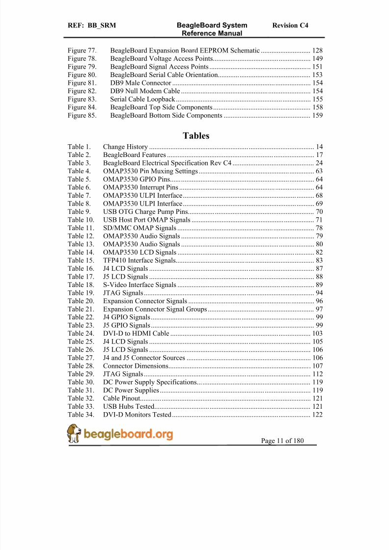
Figures
Figure 1. BeagleBoard Usage Scenarios ...................................................................... 16Figure 2. USB Y-Cable ................................................................................................ 19Figure 3. The Rev C4 Box............................................................................................ 26Figure 4. Rev C4 Box Contents.................................................................................... 27Figure 5. USB OTG Connection .................................................................................. 28Figure 6. USB Host Connection................................................................................... 29Figure 7. DC Power Connection .................................................................................. 30Figure 8. BeagleBoard JTAG Connection ................................................................... 31Figure 9. BeagleBoard Serial Cable Connection.......................................................... 32Figure 10. BeagleBoard S-Video Connection ............................................................ 33Figure 11. BeagleBoard DVI-D Connection .............................................................. 34
Figure 12. BeagleBoard Audio Out Cable Connection.............................................. 35Figure 13. BeagleBoard Audio In Cable Connection................................................. 36Figure 14. BeagleBoard Indicator Locations ............................................................. 37Figure 15. BeagleBoard Button Location................................................................... 38Figure 16. BeagleBoard SD/MMC Location ............................................................. 39Figure 17. BeagleBoard LCD Header Location......................................................... 40Figure 18. BeagleBoard High Level Block Diagram................................................. 41Figure 19. BeagleBoard Top Side Components ......................................................... 42Figure 20. BeagleBoard Backside Components......................................................... 43Figure 21. Input Power Section.................................................................................. 44Figure 22. Processor Current Measurement ............................................................... 47
Figure 23. Power Conditioning .................................................................................. 48Figure 24. Main Power Rails...................................................................................... 50Figure 25. Peripheral Voltages................................................................................... 53Figure 26. Power Sequencing..................................................................................... 56Figure 27. Reset Circuitry .......................................................................................... 57Figure 28. OMAP3530 Block Diagram ..................................................................... 59Figure 29. McBSP2 Interface..................................................................................... 61Figure 30. McBSP1 Interface..................................................................................... 62

8/2/2019 Beagle Board Manual Rev. C4
http://slidepdf.com/reader/full/beagle-board-manual-rev-c4 10/180
REF: BB_SRM BeagleBoard SystemReference Manual
Revision C4
Page 10 of 180
Figure 31. McBSP3 Interface..................................................................................... 62Figure 32. POP Memory ............................................................................................ 65Figure 33. System Clocks........................................................................................... 65Figure 34. USB OTG Design ..................................................................................... 68Figure 35. USB Host Design...................................................................................... 71
Figure 36. Example of an SDIO Card ....................................................................... 74Figure 37. RS-MMC and Card................................................................................... 75Figure 38. SD/MMC Interface ................................................................................... 77Figure 39. Audio Circuitry ......................................................................................... 79Figure 40. DVI-D Interface........................................................................................ 81Figure 41. S-Video Interface ...................................................................................... 89Figure 42. RS232 Interface Design ............................................................................ 90Figure 43. RS232 Cable ............................................................................................. 91Figure 44. Indicator Design........................................................................................ 92Figure 45. JTAG Interface.......................................................................................... 93Figure 46. Expansion Header ..................................................................................... 94
Figure 47. Power Connector..................................................................................... 100Figure 48. USB OTG Connector .............................................................................. 101Figure 49. OTG Host Shorting Pads ........................................................................ 101Figure 50. S-Video Connector.................................................................................. 102Figure 51. DVI-D Connector.................................................................................... 103Figure 52. DVI-D Cable........................................................................................... 104Figure 53. Top Mount LCD Adapter........................................................................ 107Figure 54. Top Mount LCD Adapter........................................................................ 108Figure 55. Bottom Mount LCD Adapter .................................................................. 109Figure 56. Audio In Plug.......................................................................................... 110Figure 57. Audio In Plug.......................................................................................... 110
Figure 58. Audio Out Plug ....................................................................................... 111Figure 59. Audio In Plug.......................................................................................... 111Figure 60. JTAG Connector Pinout.......................................................................... 112Figure 61. JTAG 14 to 20 Pin Adapter .................................................................... 113Figure 62. JTAG Connector Pinout.......................................................................... 113Figure 63. RS232 Header ......................................................................................... 114Figure 64. RS232 Flat Cable .................................................................................... 114Figure 65. Expansion Sockets .................................................................................. 115Figure 66. Optional Battery...................................................................................... 116Figure 67. Optional Battery Location....................................................................... 117Figure 68. DC Power Supply ................................................................................... 119
Figure 69. RS232 Cable ........................................................................................... 120Figure 70. RS232 Cable Wiring............................................................................... 120Figure 71. HDMI to DVI-D Cable .......................................................................... 122Figure 72. USB to Ethernet Adapters....................................................................... 123Figure 73. USB to WiFi ........................................................................................... 124Figure 74. USB to Bluetooth.................................................................................... 125Figure 75. BeagleBoard Dimension Drawing .......................................................... 126Figure 76. BeagleBoard Bottom Stacked Daughter Card ....................................... 127
8/2/2019 Beagle Board Manual Rev. C4
http://slidepdf.com/reader/full/beagle-board-manual-rev-c4 11/180
REF: BB_SRM BeagleBoard SystemReference Manual
Revision C4
Page 11 of 180
Figure 77. BeagleBoard Expansion Board EEPROM Schematic ............................ 128Figure 78. BeagleBoard Voltage Access Points....................................................... 149Figure 79. BeagleBoard Signal Access Points ......................................................... 151Figure 80. BeagleBoard Serial Cable Orientation.................................................... 153Figure 81. DB9 Male Connector .............................................................................. 154
Figure 82. DB9 Null Modem Cable ......................................................................... 154Figure 83. Serial Cable Loopback............................................................................ 155Figure 84. BeagleBoard Top Side Components ....................................................... 158Figure 85. BeagleBoard Bottom Side Components ................................................. 159
TablesTable 1. Change History ............................................................................................. 14Table 2. BeagleBoard Features ................................................................................... 17Table 3. BeagleBoard Electrical Specification Rev C4 .............................................. 24Table 4. OMAP3530 Pin Muxing Settings ................................................................. 63
Table 5. OMAP3530 GPIO Pins................................................................................. 64Table 6. OMAP3530 Interrupt Pins ............................................................................ 64Table 7. OMAP3530 ULPI Interface.......................................................................... 68Table 8. OMAP3530 ULPI Interface.......................................................................... 69Table 9. USB OTG Charge Pump Pins....................................................................... 70Table 10. USB Host Port OMAP Signals ..................................................................... 71Table 11. SD/MMC OMAP Signals ............................................................................. 78Table 12. OMAP3530 Audio Signals ........................................................................... 79Table 13. OMAP3530 Audio Signals ........................................................................... 80Table 14. OMAP3530 LCD Signals ............................................................................. 82Table 15. TFP410 Interface Signals.............................................................................. 83
Table 16. J4 LCD Signals ............................................................................................. 87Table 17. J5 LCD Signals ............................................................................................. 88Table 18. S-Video Interface Signals ............................................................................. 89Table 19. JTAG Signals ................................................................................................ 94Table 20. Expansion Connector Signals ....................................................................... 96Table 21. Expansion Connector Signal Groups ............................................................ 97Table 22. J4 GPIO Signals ............................................................................................ 99Table 23. J5 GPIO Signals ............................................................................................ 99Table 24. DVI-D to HDMI Cable ............................................................................... 103Table 25. J4 LCD Signals ........................................................................................... 105Table 26. J5 LCD Signals ........................................................................................... 106
Table 27. J4 and J5 Connector Sources ...................................................................... 106Table 28. Connector Dimensions................................................................................ 107Table 29. JTAG Signals .............................................................................................. 112Table 30. DC Power Supply Specifications................................................................ 119Table 31. DC Power Supplies ..................................................................................... 119Table 32. Cable Pinout................................................................................................ 121Table 33. USB Hubs Tested........................................................................................ 121Table 34. DVI-D Monitors Tested.............................................................................. 122

8/2/2019 Beagle Board Manual Rev. C4
http://slidepdf.com/reader/full/beagle-board-manual-rev-c4 12/180
REF: BB_SRM BeagleBoard SystemReference Manual
Revision C4
Page 12 of 180
Table 35. SD/MMC Cards Tested............................................................................... 122Table 36. USB to Ethernet Adapters........................................................................... 123Table 37. USB to WiFi Adapters ................................................................................ 124Table 38. USB to Bluetooth Adapters ........................................................................ 125Table 39. Voltages ...................................................................................................... 150
Table 40. Troubleshooting .......................................................................................... 152Table 41. Known Issues.............................................................................................. 157

8/2/2019 Beagle Board Manual Rev. C4
http://slidepdf.com/reader/full/beagle-board-manual-rev-c4 13/180
REF: BB_SRM BeagleBoard SystemReference Manual
Revision C4
Page 13 of 180
1.0 Introduction
This document is the System Reference Manual for the BeagleBoard, a low costOMAP3530 based board supported through BeagleBoard.org. This document providesdetailed information on the overall design and usage of the BeagleBoard from the systemlevel perspective. It is not intended to provide detailed documentation of the OMAP3530 processor or any other component used on the board. It is expected that the user will refer to the appropriate documents for these devices to access detailed information.
The key sections in this document are:
Section 2.0– Change History
Provides tracking for the changes made to the System Reference Manual.Section 3.0– Definitions and References
This section provides definitions for commonly used terms and acronyms.Section 4.0– Overview
This is a high level overview of the BeagleBoard.
Section 5.0– Specification Provided here are the features and electrical specifications of the BeagleBoard.
Section 6.0-Product Contents Describes what the BeagleBoard package looks like and what is included in the box.
Section 7.0– Hookup
Covered here is how to connect the various cables to the BeagleBoard.
Section 8.0– System Architecture and Design
This section provides information on the overall architecture and design of theBeagleBoard. This is a very detailed section that goes into the design of eachcircuit on the board.
Section 9.0– Connector Pinouts and Cables
The section describes each connector and cable used in the system. This willallow the user to create cables, purchase cables, or to perform debugging asneeded.
Section 10.0– BeagleBoard Accessories
Covered in this section are a few of the accessories that may be used withBeagleBoard. This is not an exhaustive list, but does provide an idea of the typesof cables and accessories that can be supported and how to find them. It also
provides a definition of what they need to be. It does not guarantee that thesedevices will work on all OS implementations.
Section 11.0 – Mechanical
Information is provided here on the dimensions of the BeagleBoard.
Section 12.0 – Board Verification A description is provided on how to setup the board and using the verification process and SW to verify that the board is functional.

8/2/2019 Beagle Board Manual Rev. C4
http://slidepdf.com/reader/full/beagle-board-manual-rev-c4 14/180
REF: BB_SRM BeagleBoard SystemReference Manual
Revision C4
Page 14 of 180
Section 13.0 – Troubleshooting Here is where you can find tips on troubleshooting the setup of the BeagleBoard.
Section 14.0- Known Issues
This section describes the known issues with the current revision of theBeagleBoard and any workarounds that may be possible.
Section 15.0- BeagleBoard Components This section provides information on the top and bottom side silkscreen of theBeagleBoard showing the location of the components.
Section 16.0- BeagleBoard Schematics
These are the schematics for the BeagleBoard and information on where to get thePDF and OrCAD files..
Section 17.0- Bill Of Material
This section describes where to get the latest Bill of Material for the BeagleBoard.
Section 18.0- BeagleBoard PCB Information This section describes where to get the PCB file information for the BeagleBoard.
2.0 Change History
2.1 Change History
Table 1 tracks the changes made for each revision of this document.
Table 1. Change History
Rev Changes Date By
C4 Initial release. 12/15/2009 GC
2.2 Revision C3 vs. C4
There are three key changes on the Rev C4 board versus the Rev C3 version.
o Use of the OMAP3530DCBB72 device which is the 720MHZ version of theOMAP3530.
o An updated version of the UBoot software. The following changes will affect theuser experience:
o The Beagle splash screen has been replaced with an orange only screen at boot up.
o Turning on VAUX2 for the EHCI fixo A more advanced fix for the EHCI noise issue on Rev C3 board. This involves a
change in the power circuitry for the 1.8V rail supplied to the EHCI PHY
8/2/2019 Beagle Board Manual Rev. C4
http://slidepdf.com/reader/full/beagle-board-manual-rev-c4 15/180
REF: BB_SRM BeagleBoard SystemReference Manual
Revision C4
Page 15 of 180
interface. The power is now derived from the VAUX2 on the TPS65950 through afilter circuit.
3.0 Definitions and References
3.1 Definitions
SD- Secure DigitalSDIO- Secure Digital Input OutputMMC- Multimedia CardMDDR - Mobile Dual Data RateSDRAM- Synchronous Dual Access MemoryOMAP3530- The CortexA8 based System on a Chip from Texas Instruments.
4.0 BeagleBoard Overview
The BeagleBoard is an OMAP3530 platform designed specifically to address the OpenSource Community. It has been equipped with a minimum set of features to allow theuser to experience the power of the OMAP3530 and is not intended as a full development platform as many of the features and interfaces supplied by the OMAP3530 are notaccessible from the BeagleBoard. By utilizing standard interfaces, the BeagleBoard ishighly extensible to add many features and interfaces. It is not intended for use in end products. All of the design information is freely available and can be used as the basis for a product. BeagleBoards will not be sold for use in any product as this hampers theability to get the boards to as many community members as possible and to grow thecommunity.
4.1 BeagleBoard Usage Scenarios
The Figure 1 provides an example of a few of the various usage scenarios for theBeagleBoard.

8/2/2019 Beagle Board Manual Rev. C4
http://slidepdf.com/reader/full/beagle-board-manual-rev-c4 16/180
REF: BB_SRM BeagleBoard SystemReference Manual
Revision C4
Page 16 of 180
Figure 1. BeagleBoard Usage Scenarios
SD
USBBatter
WiFi
GP
beale>

8/2/2019 Beagle Board Manual Rev. C4
http://slidepdf.com/reader/full/beagle-board-manual-rev-c4 17/180
REF: BB_SRM BeagleBoard SystemReference Manual
Revision C4
Page 17 of 180
5.0 BeagleBoard Specification
This section covers the specifications of the BeagleBoard and provides a high leveldescription of the major components and interfaces that make up the BeagleBoard.
5.1 BeagleBoard Features
Table 2 provides a list of the BeagleBoard’s features.
Table 2. BeagleBoard Features
Feature
Processor OMAP3530DCBB72 720MHz
MicronPOP Memory 2Gb NAND (256MB) 2Gb MDDR SDRAM (256MB)
Power Regulators
Audio CODEC
ResetPMIC TPS65950
USB OTG PHY
14-pin JTAG GPIO PinsDebug Support
UART LEDs
PCB 3.1” x 3.0” (78.74 x 76.2mm) 6 layers
Power 2-User ControllableIndicators
PMU
Mini AB USB connector TPS65950 I/F
HS USB 2.0 OTG
PortMiniAB
HS USB Host Port Single USB HS Port Up to 500ma Power
3.5mm 3.5mmAudio Connectors
L+R out L+R Stereo In
SD/MMC Connector 6 in 1 SD/MMC/SDIO 4/8 bit support, Dual voltage
User Interface 1-User defined button Reset Button
Video DVI-D S-Video
Power Connector USB Power DC Power
Power (5V & 1.8V) UARTMcBSP McSPI
I2C GPIO
Expansion
Connector
(Not Populated)MMC PWM
2 LCD Connectors Access to all of the LCDcontrol signals plus I2C
3.3V, 5V, 1.8V

8/2/2019 Beagle Board Manual Rev. C4
http://slidepdf.com/reader/full/beagle-board-manual-rev-c4 18/180
REF: BB_SRM BeagleBoard SystemReference Manual
Revision C4
Page 18 of 180
The following sections provide more detail on each feature and sections of theBeagleBoard.
5.2 OMAP Processor
The BeagleBoard uses the OMAP3530DCBB72 720MHZ version and comes in a .4mm pitch POP package. POP (Package on Package) is a technique where the memory, NANDand SDRAM, are mounted on top of the OMAP3530. For this reason, when looking atthe BeagleBoard, you will not find an actual part labeled OMAP3530.
5.3 Memory
The Micron POP memory is used on the Rev C4 BeagleBoard and is mounted on top of the processor as mentioned. The key function of the POP memory is to provide:
o 2Gb NAND x 16 (256MB)o 2Gb MDDR SDRAM x32 (256MB @ 166MHz)
No other memory devices are on the BeagleBoard. It is possible however, that additionalmemory can be added to BeagleBoard by:
o Installing a SD or MMC in the SD/MMC sloto Use the USB OTG port and a powered USB hub to drive a USB Thumb drive or
hard drive.o Install a thumbdrive into the EHCI USB port
Support for this is dependent upon driver support in the OS.
5.4 Power Management
The TPS65950 is used on the Rev C4 to provide power to the BeagleBoard with theexception of the 3.3V regulator which is used to provide power to the DVI-D encoder andRS232 driver. In addition to the power the TPS65950 also provides:
o Stereo Audio Out
o Stereo Audio ino Power on reseto USB OTG PHYo Status LED

8/2/2019 Beagle Board Manual Rev. C4
http://slidepdf.com/reader/full/beagle-board-manual-rev-c4 19/180
REF: BB_SRM BeagleBoard SystemReference Manual
Revision C4
Page 19 of 180
5.5 HS USB 2.0 OTG Port
The USB OTG port can be used as the primary power source and communication link for the BeagleBoard and derives power from the PC over the USB cable. The client port islimited in most cases to 500mA by the PC. A single PC USB port is sufficient to power
the BeagleBoard. If additional devices are connected to the expansion bus and the 5V railis used to power them or if a high powered USB device is connected to the EHCI port,then the power required could exceed that supplied by a USB port or Hub.
It is possible to take this to 1A by using a Y cable if additional power is needed for either the USB host port or an expansion card. Figure 2 shows and example of the Y-Cable for the USB.
Figure 2. USB Y-Cable
The BeagleBoard requires a single minAB to USB A cable or as mentioned a Y-Cablecan be used if needed.
There is an option to provide external power to the BeagleBoard using a 5V DC supplyand is discussed later in this section.
5.6 HS USB 2.0 Host Port
On the Rev C4 board a single USB HS only Host port is provided via a USB Type Aconnector. It provides power on/off control and up to 500mA of current at 5V.
The HS USB Port is HS only. In order to support a FS/LS device, a HUB must be used.

8/2/2019 Beagle Board Manual Rev. C4
http://slidepdf.com/reader/full/beagle-board-manual-rev-c4 20/180
REF: BB_SRM BeagleBoard SystemReference Manual
Revision C4
Page 20 of 180
5.7 Stereo Audio Output Connector
A 3.5mm standard stereo output audio jack is provided to access the stereo output of theonboard audio CODEC. The Audio CODEC is provided by the TPS65950.
5.8 Stereo Audio In Connector
A 3.5mm standard stereo audio input jack is provided to access the stereo output of theonboard audio CODEC.
5.9 S-Video Connector
A 4 pin DIN connector is provided to access the S-Video output of the BeagleBoard. Thisis a separate output from the OMAP processor and can contain different video output datafrom what is found on the DVI-D output if the software is configured to do it.
It will support NTSC or PAL format output to a standard TV. The default is NTSC, butcan be changed via the Software.
5.10 DVI-D Connector
The BeagleBoard can drive a LCD panel equipped with a DVI-D digital input. This isthe standard LCD panel interface of the OMAP3530 and will support 24b color output.DDC2B (Display Data Channel) or EDID (Enhanced Display ID) support over I2C is provided in order to allow for the identification of the LCD monitor type and the requiredsettings.
The BeagleBoard is equipped with a DVI-D interface that uses an HDMI connector thatwas selected for its small size. It does not support the full HDMI interface and is used to provide the DVI-D interface portion only. The user must use a HDMI to DVI-D cable or adapter to connect to a LCD monitor. This cable or adapter is not provided with theBeagleBoard. A standard HDMI cable can be used when connecting to a monitor with anHDMI connector.
DO NOT PLUG IN THE DVI-D CONNECTOR TO A DISPLAY WITH THE
BEAGLEBAORD POWERED ON. PLUG IN THE CABLE TO THE DISPLAY
AND THEN POWER ON THE BEAGLEBOARD.
5.11 LCD Header
A pair of 1.27mm pitch 2x10 headers are provided to gain access to the LCD signals.This allows for the creation of LCD boards that will allow adapters to be made to providethe level translation to support different LCD panels.

8/2/2019 Beagle Board Manual Rev. C4
http://slidepdf.com/reader/full/beagle-board-manual-rev-c4 21/180
REF: BB_SRM BeagleBoard SystemReference Manual
Revision C4
Page 21 of 180
5.12 SD/MMC 6 in 1 Connector
A 6 in 1 SD/MMC connector is provided as a means for expansion and can support suchdevices as:
o WiFi Cardso Camerao Bluetooth Cardso GPS Moduleso SD Memory Cardso MMC Memory Cardso SDIO Cardso MMCMobile cardso RS-MMC Cardso miniSD Cards
It supports the MMC4.0 (MMC+) standard and can boot from MMC or SD cards. It willsupport both 4 and 8 bit cards. It will also support most SDHC cards as well.
5.13 Reset Button
When pressed and released, causes a power on reset of the BeagleBoard.
5.14 User/Boot Button
A button is provided on the BeagleBoard to provide two functions:
• Force a change in the boot sequence of the OMAP3530.• Used as an application button that can be used by SW as needed.
When used in conjunction with the RESET button, it will force a change to the order inwhich boot sources are checked as viable boot sources.
If the button is pressed while the RESET button is released, the sequence becomes:
o USBo UARTo MMC1
o NAND
Even though the NAND may have a program in it, if a card is placed in the MMC slot, itwill try to boot from it first. If it is not there, it will boot from NAND.
There is also the option to have a serial download application that will program the NAND if connected to the serial or USB ports. In this scenario the internal ROM will

8/2/2019 Beagle Board Manual Rev. C4
http://slidepdf.com/reader/full/beagle-board-manual-rev-c4 22/180
REF: BB_SRM BeagleBoard SystemReference Manual
Revision C4
Page 22 of 180
stop on either the serial or USB port and start the download process from there. It doesrequire an application to be run on the host PC in order to perform this function.
If the user button is not pressed at reset, the sequence in which the internal ROM looksfor viable boot sources is as follows:
o NANDo USBo UART3o MMC1
In this case, NAND overrides every option and will always boot from NAND if there isdata in the NAND. If the NAND is empty, then the other sources are available to be used based on the boot order.
To force a boot from the SD/MMC card, the reset button must be pushed and the reset
button pushed and reelased.
5.15 Indicators
There are three green LEDs on the BeagleBoard that can be controlled by the user.
o One on the TPS65950 that is programmed via the I2C interfaceo Two on the OMAP3530 Processor controlled via GPIO pins
There is a fourth LED on the BeagleBoard that provides an indication that power is
supplied to the board and is not controlled via software.
5.16 Power Connector
Power will be supplied via the USB OTG connector and if a need arises for additional power, such as when a board is added to the expansion connectors, a larger wall supply5V can be plugged into the optional power jack. When the wall supply is plugged in, itwill remove the power path from the USB connector and will be the power source for thewhole board. The power supply is not provided with the BeagleBoard.
When using the USB OTG port in the host mode, the DC supply must be connected asthe USB port will be used to provide limited power to the hub at a maximum of 100mA,so a hub must be powered. The 100mA is not impacted by having a higher amperagesupply plugged into the DC power jack. The 100mA is a function of the OTG port itself.
WARNING: DO NOT PLUG IN ANYTHING BUT 5V TO THE DC
CONNECTOR OR THE BOARD WILL BE DAMAGED!

8/2/2019 Beagle Board Manual Rev. C4
http://slidepdf.com/reader/full/beagle-board-manual-rev-c4 23/180
REF: BB_SRM BeagleBoard SystemReference Manual
Revision C4
Page 23 of 180
Make sure the DC supply is regulated and a clean supply.
5.17 JTAG Connector
A 14 pin JTAG header is provided on the BeagleBoard to facilitate the SW development
and debugging of the board by using various JTAG emulators. The interface is at 1.8V onall signals. Only 1.8V Levels are supported. DO NOT expose the JTAG header to
3.3V.
5.18 RS232 Header
Support for RS232 via UART3 is provided by a 10 pin header on the BeagleBoard for access to an onboard RS232 transceiver. It does require an IDC to DB9 flat cable, whichis not provided, to access the serial port.
5.19 Expansion Header
An option for a single 28 pin header is provided on the board to allow for the connectionof various expansion cards that could be developed by the users or other sources. Due tomultiplexing, different signals can be provided on each pin. This header is not populatedon the BeagleBoard so that based on the usage scenario it can be populated as needed.
5.20 BeagleBoard Mechanical Specifications
Size: 3.0” x 3.1”Max height: TBMLayers: 6PCB thickness: .062”RoHS Compliant: YesWeight: TBW
8/2/2019 Beagle Board Manual Rev. C4
http://slidepdf.com/reader/full/beagle-board-manual-rev-c4 24/180
REF: BB_SRM BeagleBoard SystemReference Manual
Revision C4
Page 24 of 180
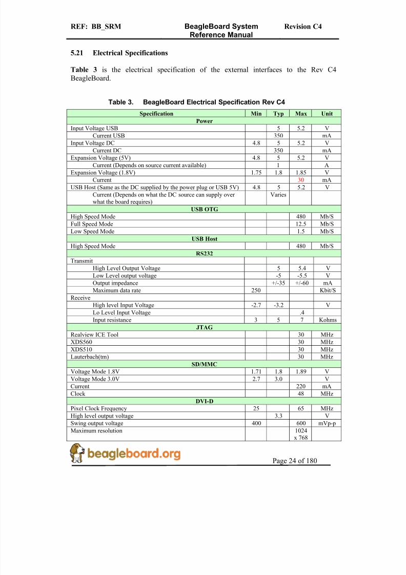
5.21 Electrical Specifications
Table 3 is the electrical specification of the external interfaces to the Rev C4BeagleBoard.
Table 3. BeagleBoard Electrical Specification Rev C4
Specification Min Typ Max Unit
Power
Input Voltage USB 5 5.2 V
Current USB 350 mA
Input Voltage DC 4.8 5 5.2 V
Current DC 350 mA
Expansion Voltage (5V) 4.8 5 5.2 V
Current (Depends on source current available) 1 A
Expansion Voltage (1.8V) 1.75 1.8 1.85 V
Current 30 mA
USB Host (Same as the DC supplied by the power plug or USB 5V) 4.8 5 5.2 VCurrent (Depends on what the DC source can supply over what the board requires)
Varies
USB OTG
High Speed Mode 480 Mb/S
Full Speed Mode 12.5 Mb/S
Low Speed Mode 1.5 Mb/S
USB Host
High Speed Mode 480 Mb/S
RS232
Transmit
High Level Output Voltage 5 5.4 V
Low Level output voltage -5 -5.5 V
Output impedance +/-35 +/-60 mAMaximum data rate 250 Kbit/S
Receive
High level Input Voltage -2.7 -3.2 V
Lo Level Input Voltage .4
Input resistance 3 5 7 Kohms
JTAG
Realview ICE Tool 30 MHz
XDS560 30 MHz
XDS510 30 MHz
Lauterbach(tm) 30 MHz
SD/MMC
Voltage Mode 1.8V 1.71 1.8 1.89 V
Voltage Mode 3.0V 2.7 3.0 V
Current 220 mA
Clock 48 MHz
DVI-D
Pixel Clock Frequency 25 65 MHz
High level output voltage 3.3 V
Swing output voltage 400 600 mVp-p
Maximum resolution 1024x 768

8/2/2019 Beagle Board Manual Rev. C4
http://slidepdf.com/reader/full/beagle-board-manual-rev-c4 25/180
REF: BB_SRM BeagleBoard SystemReference Manual
Revision C4
Page 25 of 180
S-Video
Full scale output voltage (75ohm load) .7 .88 1 V
Offset voltage 50 mV
Output Impedance 67.5 75 82.5 Ohms
Audio In
Peak-to-peak single-ended input voltage (0 dBFs) 1.5 Vpp
Total harmonic distortion (sine wave @ 1.02 kHz @ -1 dBFs) -80 -75 dB
Total harmonic distortion (sine wave @ 1.02 kHz) 20 Hz to 20 kHz, A-weighted audio, Gain = 0 dB
-85 -78 dB
Audio Out
Load Impedance @100 pF 14 16 ohms
Maximum Output Power (At 0.53 Vrms differential output voltageand load impedance = 16 Ohms)
17.56 mW
Peak-to-Peak output voltage 1.5 Vpp
Total Harmonic Distortion @ 0 dBFs -80 -75 dB
Idle channel noise (20Hz to 20KHz) -90 -85 dB
8/2/2019 Beagle Board Manual Rev. C4
http://slidepdf.com/reader/full/beagle-board-manual-rev-c4 26/180
REF: BB_SRM BeagleBoard SystemReference Manual
Revision C4
Page 26 of 180
6.0 Product Contents
Under this section is a description of what comes in the box when the BeagleBoard is purchased.
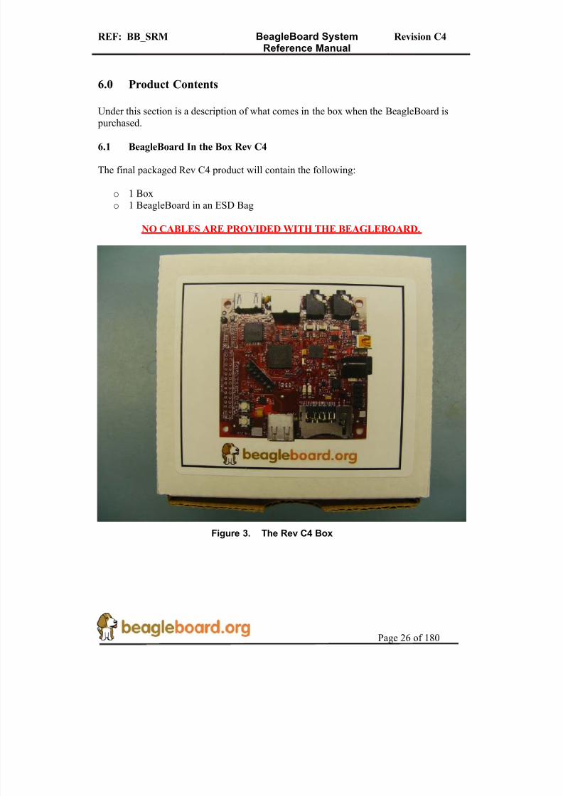
6.1 BeagleBoard In the Box Rev C4
The final packaged Rev C4 product will contain the following:
o 1 Boxo 1 BeagleBoard in an ESD Bag
NO CABLES ARE PROVIDED WITH THE BEAGLEBOARD.
Figure 3. The Rev C4 Box

8/2/2019 Beagle Board Manual Rev. C4
http://slidepdf.com/reader/full/beagle-board-manual-rev-c4 27/180
REF: BB_SRM BeagleBoard SystemReference Manual
Revision C4
Page 27 of 180
Figure 4. Rev C4 Box Contents
6.2 Software on the BeagleBoard
The board ships with U-Boot and X-Loader flashed onto the BeagleBoard.
6.3 Repair
If you feel the board is in need of repair, follow the RMA Request process found athttp://beagleboard.org/support/rma
8/2/2019 Beagle Board Manual Rev. C4
http://slidepdf.com/reader/full/beagle-board-manual-rev-c4 28/180

8/2/2019 Beagle Board Manual Rev. C4
http://slidepdf.com/reader/full/beagle-board-manual-rev-c4 29/180
REF: BB_SRM BeagleBoard SystemReference Manual
Revision C4
Page 29 of 180
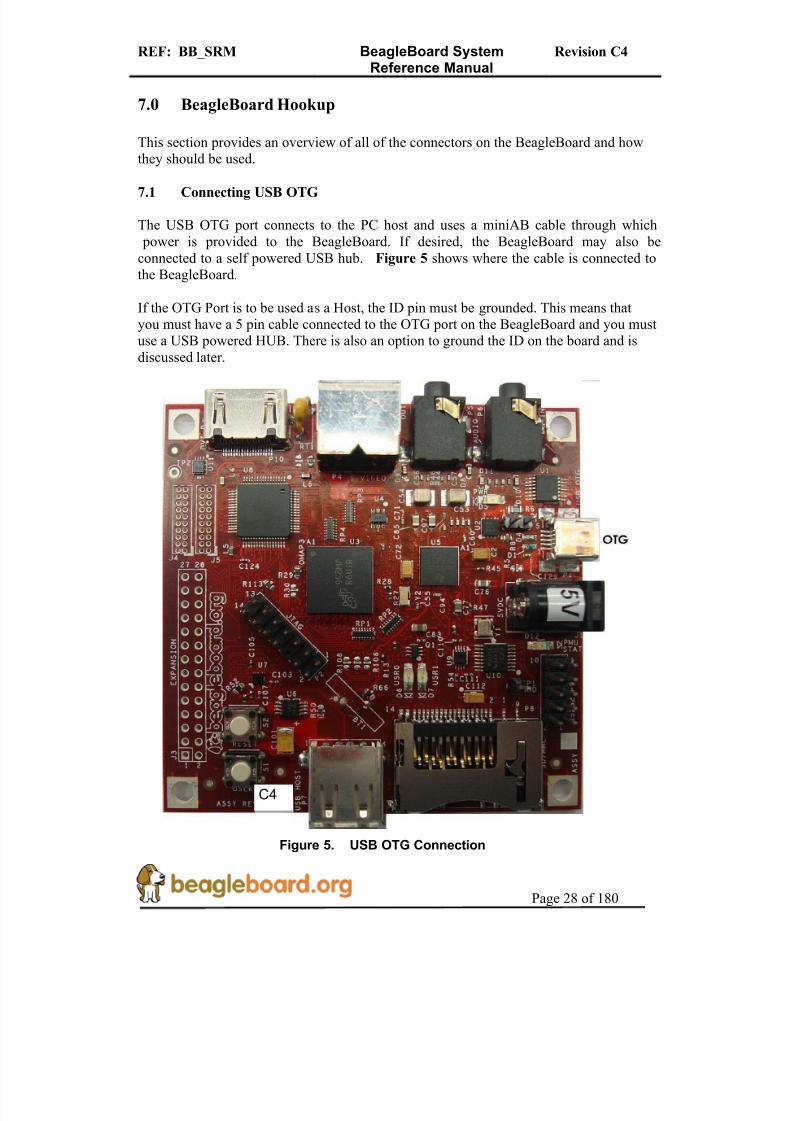
7.2 Connecting USB Host
The Rev C4 Beagle is equipped with a USB Host only connector and can be used tosupport USB based devices. In order to connect multiple devices a Hub is required. Thehub can be powered or un-powered if the total current on the devices connected to the
hub do not exceed the available power from the DC power supply that is used. If the board is powered from the OTG connector, then the power available from this port isextremely limited and will not be able to provide sufficient power to run most USBdevices. It may be possible to run a USB keyboard or mouse, but that is about all it willhave the power to supply. The USB Host port is HS only and does not support LS or FSdevices without a hub.
Figure 6 below shows the location of the USB Host connector.
Figure 6. USB Host Connection
C4

8/2/2019 Beagle Board Manual Rev. C4
http://slidepdf.com/reader/full/beagle-board-manual-rev-c4 30/180
REF: BB_SRM BeagleBoard SystemReference Manual
Revision C4
Page 30 of 180
7.3 Connecting Optional Power
An optional DC supply can be used to power the BeagleBoard by plugging it into the power jack of the BeagleBoard. The power supply is not provided with the BeagleBoard, but can be obtained from various sources. You need to make sure the supply is a
regulated 5V supply. Figure 7 shows where to insert the power supply into the power jack.
Figure 7. DC Power Connection
The power supply must have a 2.1mm I.D x 5.5mm O.D. x 9.5mm and can be either straight or right angle. Connecting anything other than 5V will result in damage to the board. If you are using the USB OTG port in the OTG or host mode, you must have anexternal DC supply powering the BeagleBoard.
It is highly recommended that on the Rev C4 version of the board that an external power supply or double USB cable be used if the USB Host is to be used. Most USB supplieswill not be able to supply the required current over a single USB port.
C4

8/2/2019 Beagle Board Manual Rev. C4
http://slidepdf.com/reader/full/beagle-board-manual-rev-c4 31/180
REF: BB_SRM BeagleBoard SystemReference Manual
Revision C4
Page 31 of 180
7.4 Connecting JTAG
A JTAG emulator can be used for advanced debugging by connecting it to the JTAGheader on the BeagleBoard. Only the 14pin version of the JTAG is supported and if a20pin version is needed, you will to contact your emulator supplier for the appropriate
adapter. Figure 8 shows the connection of the JTAG cable to the BeagleBoard.
Figure 8. BeagleBoard JTAG Connection
DO NOT expose the JTAG header to 3.3V. It supports 1.8V only.
C4
8/2/2019 Beagle Board Manual Rev. C4
http://slidepdf.com/reader/full/beagle-board-manual-rev-c4 32/180
REF: BB_SRM BeagleBoard SystemReference Manual
Revision C4
Page 32 of 180
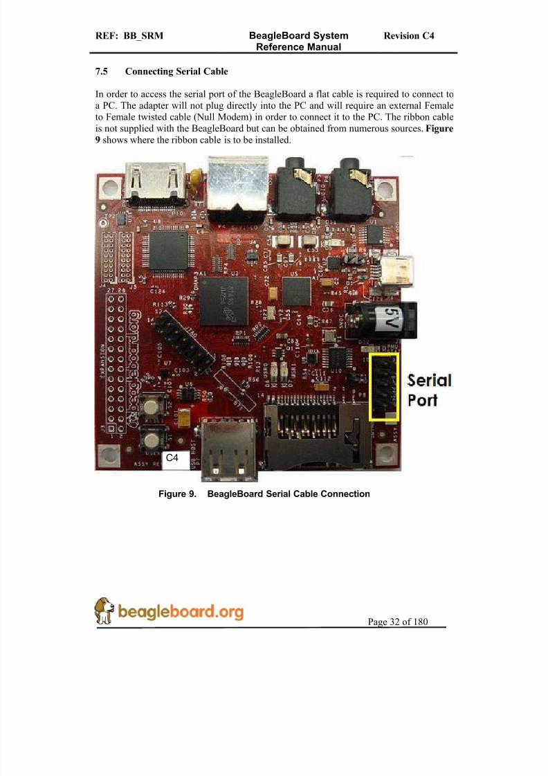
7.5 Connecting Serial Cable
In order to access the serial port of the BeagleBoard a flat cable is required to connect toa PC. The adapter will not plug directly into the PC and will require an external Femaleto Female twisted cable (Null Modem) in order to connect it to the PC. The ribbon cable
is not supplied with the BeagleBoard but can be obtained from numerous sources. Figure9 shows where the ribbon cable is to be installed.
Figure 9. BeagleBoard Serial Cable Connection
C4
8/2/2019 Beagle Board Manual Rev. C4
http://slidepdf.com/reader/full/beagle-board-manual-rev-c4 33/180
REF: BB_SRM BeagleBoard SystemReference Manual
Revision C4
Page 33 of 180
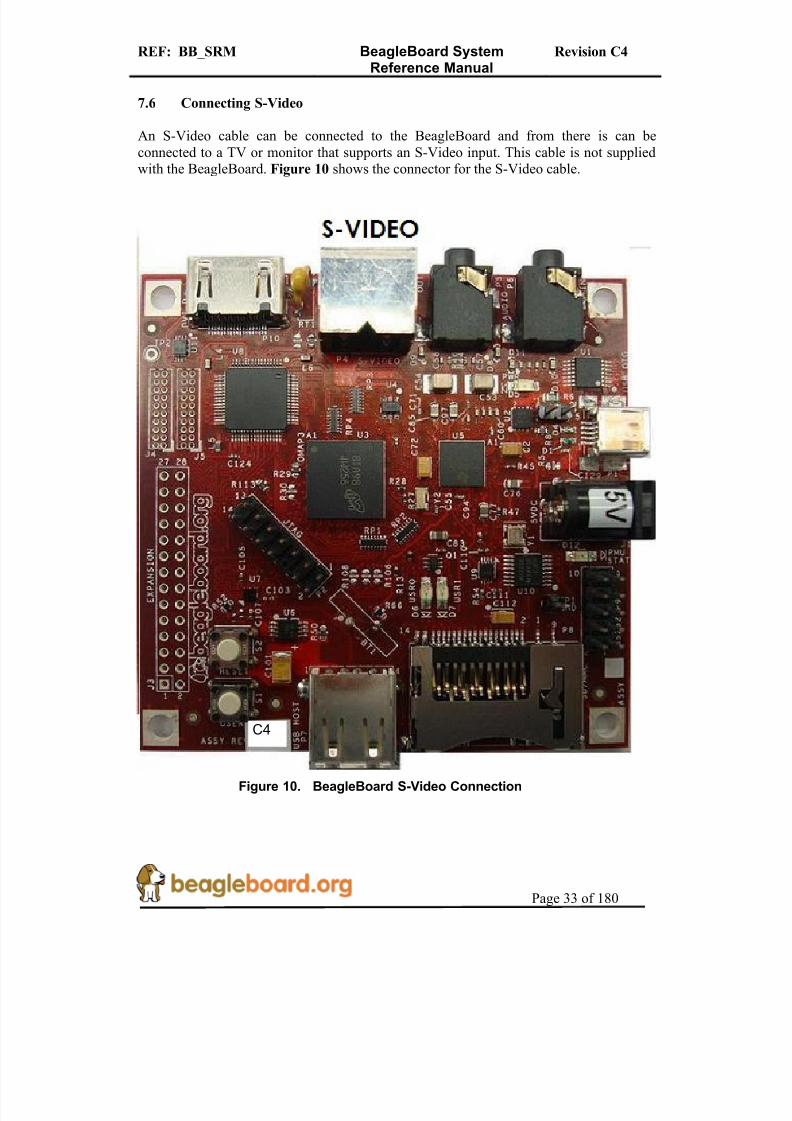
7.6 Connecting S-Video
An S-Video cable can be connected to the BeagleBoard and from there is can beconnected to a TV or monitor that supports an S-Video input. This cable is not suppliedwith the BeagleBoard. Figure 10 shows the connector for the S-Video cable.
Figure 10. BeagleBoard S-Video Connection
C4

8/2/2019 Beagle Board Manual Rev. C4
http://slidepdf.com/reader/full/beagle-board-manual-rev-c4 34/180
REF: BB_SRM BeagleBoard SystemReference Manual
Revision C4
Page 34 of 180
7.7 Connecting DVI-D Cable
In order to connect the DVI-D output to a monitor, a HDMI to DVI-D cable is required.This cable is not supplied with BeagleBoard but can be obtained through numeroussources. Figure 11 shows the proper connection point for the cable.
Figure 11. BeagleBoard DVI-D Connection
DO NOT PLUG IN THE DVI-D CONNECTOR TO A DISPLAY WITH THE
BEAGLEBAORD POWERED ON. PLUG IN THE CABLE TO THE DISPLAY
AND THEN POWER ON THE BEAGLEBOARD.
Only the digital portion of HDMI is supported on theBeagleBoard.
C4

8/2/2019 Beagle Board Manual Rev. C4
http://slidepdf.com/reader/full/beagle-board-manual-rev-c4 35/180
REF: BB_SRM BeagleBoard SystemReference Manual
Revision C4
Page 35 of 180
7.8 Connecting Stereo Out Cable
An external Audio output device, such as external stereo powered speakers, can beconnected to the BeagleBoard via a 3.5mm jack. The audio cables are not provided withBeagleBoard, but can be obtained from just about anywhere. Figure 12 shows how the
cable connected to the stereo out jack.
Figure 12. BeagleBoard Audio Out Cable Connection
C4

8/2/2019 Beagle Board Manual Rev. C4
http://slidepdf.com/reader/full/beagle-board-manual-rev-c4 36/180
REF: BB_SRM BeagleBoard SystemReference Manual
Revision C4
Page 36 of 180
7.9 Connecting Stereo In Cable
External Audio input devices, such as a powered microphone or the audio output of a PCor MP3 player, can be connected to the via a 3.5mm jack. The audio cables are not provided with BeagleBoard, but can be obtained from just about any source. Figure 13
shows how the cable is connected to the stereo input jack.
Figure 13. BeagleBoard Audio In Cable Connection
C4

8/2/2019 Beagle Board Manual Rev. C4
http://slidepdf.com/reader/full/beagle-board-manual-rev-c4 37/180
REF: BB_SRM BeagleBoard SystemReference Manual
Revision C4
Page 37 of 180
7.10 Indicator Locations
There are four green indicators on the BeagleBoard. One of them, POWER, indicatesthat the main supply is active. The other three can be controlled by the software. Figure
14 shows the location of each indicator.
Figure 14. BeagleBoard Indicator Locations
C4

8/2/2019 Beagle Board Manual Rev. C4
http://slidepdf.com/reader/full/beagle-board-manual-rev-c4 38/180
REF: BB_SRM BeagleBoard SystemReference Manual
Revision C4
Page 38 of 180
7.11 Button Locations
There are two buttons on the BeagleBoard; the RESET button when pressed will force a board reset and the USER button which can be used by the SW for user interaction. If theuser holds the USER button down while pressing and releasing the RESET button, the
BeagleBoard will enter the ROM boot loader mode allowing it to boot from other sourcesthan the onboard NAND. Figure 15 shows the location of the buttons.
Figure 15. BeagleBoard Button Location
C4

8/2/2019 Beagle Board Manual Rev. C4
http://slidepdf.com/reader/full/beagle-board-manual-rev-c4 39/180
REF: BB_SRM BeagleBoard SystemReference Manual
Revision C4
Page 39 of 180
7.12 SD/MMC Connection
The SD/MMC connector can be used for Memory or SDIO type cards. This is a full sizeconnector and will support various cards. Whether a particular card is supported or not, isdependent on the available software drivers. Figure 16 shows the location of the
SD/MMC connector.
Figure 16. BeagleBoard SD/MMC Location
C4

8/2/2019 Beagle Board Manual Rev. C4
http://slidepdf.com/reader/full/beagle-board-manual-rev-c4 40/180
REF: BB_SRM BeagleBoard SystemReference Manual
Revision C4
Page 40 of 180
7.13 LCD Connection
There are two headers provided to allow access to the LCD signals on the BeagleBoard.These headers are 2x10 headers with a spacing of .05 (1.27mm) pitch. How theseconnectors are used is determined by the design of the adapter board. Figure 17 shows
the location of the LCD headers on the Beagle.
Figure 17. BeagleBoard LCD Header Location
C4
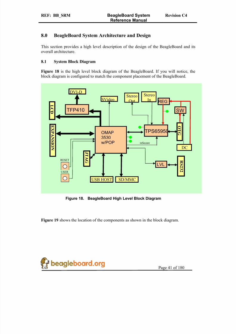
8/2/2019 Beagle Board Manual Rev. C4
http://slidepdf.com/reader/full/beagle-board-manual-rev-c4 41/180
REF: BB_SRM BeagleBoard SystemReference Manual
Revision C4
Page 41 of 180
8.0 BeagleBoard System Architecture and Design
This section provides a high level description of the design of the BeagleBoard and itsoverall architecture.
8.1 System Block Diagram
Figure 18 is the high level block diagram of the BeagleBoard. If you will notice, the block diagram is configured to match the component placement of the BeagleBoard.
Figure 18. BeagleBoard High Level Block Diagram
Figure 19 shows the location of the components as shown in the block diagram.
OMAP3530w/POP
TFP410
L
CD
SVideo
TPS65950
OT G
StereoIn
StereoOut
SW
DC
REG
EXP A N S I O N
R S 2 3 2
LVL
SD/MMC
J TA G
RESET
USER
DVI-D
USB HOST
mSecure

8/2/2019 Beagle Board Manual Rev. C4
http://slidepdf.com/reader/full/beagle-board-manual-rev-c4 42/180
REF: BB_SRM BeagleBoard SystemReference Manual
Revision C4
Page 42 of 180
Figure 19. BeagleBoard Top Side Components
There are no key components on the back of the BeagleBoard, but Figure 20 has been provided for completeness.
C4
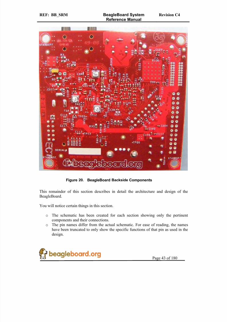
8/2/2019 Beagle Board Manual Rev. C4
http://slidepdf.com/reader/full/beagle-board-manual-rev-c4 43/180
REF: BB_SRM BeagleBoard SystemReference Manual
Revision C4
Page 43 of 180
Figure 20. BeagleBoard Backside Components
This remainder of this section describes in detail the architecture and design of theBeagleBoard.
You will notice certain things in this section.
o The schematic has been created for each section showing only the pertinentcomponents and their connections.
o The pin names differ from the actual schematic. For ease of reading, the nameshave been truncated to only show the specific functions of that pin as used in thedesign.
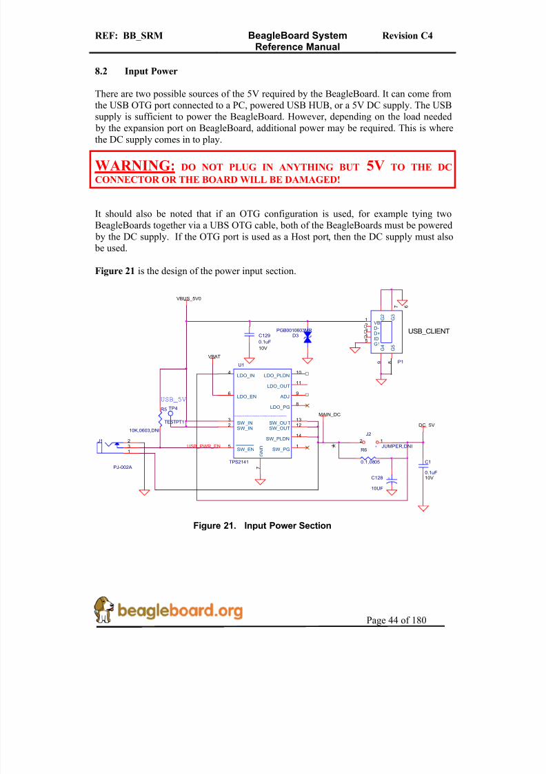
8/2/2019 Beagle Board Manual Rev. C4
http://slidepdf.com/reader/full/beagle-board-manual-rev-c4 44/180
REF: BB_SRM BeagleBoard SystemReference Manual
Revision C4
Page 44 of 180
8.2 Input Power
There are two possible sources of the 5V required by the BeagleBoard. It can come fromthe USB OTG port connected to a PC, powered USB HUB, or a 5V DC supply. The USBsupply is sufficient to power the BeagleBoard. However, depending on the load needed
by the expansion port on BeagleBoard, additional power may be required. This is wherethe DC supply comes in to play.
WARNING: DO NOT PLUG IN ANYTHING BUT 5V TO THE DC
CONNECTOR OR THE BOARD WILL BE DAMAGED!
It should also be noted that if an OTG configuration is used, for example tying twoBeagleBoards together via a UBS OTG cable, both of the BeagleBoards must be powered by the DC supply. If the OTG port is used as a Host port, then the DC supply must also
be used.
Figure 21 is the design of the power input section.
USB_CLIENT
R5
10K,0603,DNI
P1
23
1
4
7 6
5
8 9
D-D+
VB
ID
G 2
G 3
G1
G 5
G 4
MAIN_DC
R6
0.1,0805
*
C1
0.1uF10V
+
J2
JUMPER,DNI12
+C128
10UF
VBUS_5V0
D3PGB0010603MR
TP4
TESTPT1
USB_5V
VBAT
J1
PJ-002A
231
USB_PWR_EN
U1
TPS2141
4
6
2
7
10
11
9
8
12
14
15
3 13
LDO_IN
LDO_EN
SW_IN
G N D
LDO_PLDN
LDO_OUT
ADJ
LDO_PG
SW_OUT
SW_PLDN
SW_PGSW_EN
SW _IN SW_OU T
C129
0.1uF
10V
DC_5V
Figure 21. Input Power Section

8/2/2019 Beagle Board Manual Rev. C4
http://slidepdf.com/reader/full/beagle-board-manual-rev-c4 45/180
REF: BB_SRM BeagleBoard SystemReference Manual
Revision C4
Page 45 of 180
8.2.1 USB DC Source
The USB specification requires that the current consumed prior to enumeration be limitedto 100mA @ 5V (500mW). The 5V DC from the USB is routed through the TPS2141switch to insure that this requirement is met as uncharged capacitors on the BeagleBoard
can exhibit a large current drain during start up that could exceed this requirement. TheTPS2141 is a USB 2.0 Specification-compatible IC containing a dual-current limiting power switch and an adjustable low dropout regulator (LDO). Both the switch and LDOlimit inrush current by controlling the turn on slew rate. The dual-current-limiting featureof the switch allows USB peripherals to utilize high-value capacitance at the output of theswitch, while keeping the inrush current low.
During turn on, the switch limits the current delivered to the capacitive load to less than100 mA. When the output voltage from the switch reaches about 93% of the inputvoltage, the switch current limit increases to 800mA (minimum), at which point higher current loads can be turned on. The higher current limit provides short circuit protection
while allowing the peripheral to draw maximum current from the USB bus.
When in the USB powered mode and no DC supply is connected, the TPS2141 isenabled, allowing the power to be supplied to the board from the OTG port through theintegrated switch inside the TPS2141.
8.2.2 Wall Supply Source
A wall supply can be used to provide power to the board. A regulated 5V DC supply of atleast 500mA is required. It needs to have a 2.1mm plug with a center hot configuration.
WARNING: DO NOT PLUG IN ANYTHING BUT 5V TO THE DC
CONNECTOR OR THE BOARD WILL BE DAMAGED!
In the event that a higher DC load is required due to the addition of a Daughtercard ahigher current supply can be used. The maximum current should not exceed 2A.
8.2.3 DC Source Control
Unlike when powering from the USB OTG port, in the case of the DC voltage, the
current limiting is not required. As long as the DC supply is not connected, the switch for the USB is enabled. When the DC supply is plugged in, the switch is disabled because theground is removed from pin 5 of the TPS2141. This insures that the 5V from the USB isnot connected by disabling the internal FET. In the case where there is no USB pluggedin, there is no 5V available to be routed so the removal of the pullup in pin 5 has noaffect.

8/2/2019 Beagle Board Manual Rev. C4
http://slidepdf.com/reader/full/beagle-board-manual-rev-c4 46/180
REF: BB_SRM BeagleBoard SystemReference Manual
Revision C4
Page 46 of 180
When in the DC mode of operation, the USB OTG can be used in the Host or Clientmodes. The TPS65950 will be responsible for handling the supply of the VBUS_5V0 railin the OTG or Host modes. As this is limited to 100mA, a powered hub must be used tosupport peripherals on the OTG port.
8.2.4 3.3V Supply
The TPS2141 has an integrated 3.3V LDO which is being used to supply the 3.3V asrequired on the BeagleBoard for the DVI-D interface and the UART. The input to theLDO is supplied by the main DC_5V. This insures that the power to the LDO can besupplied by either the USB or the DC wall supply and that the current measurementincludes the 3.3V supply.
8.2.5 Meter Current Measurement
Jumper J2 is a header that allows for the voltage drop across the resistor to be measuredusing a meter, providing a way to measure the current consumption of the BeagleBoardfrom the main voltage rails, either USB or DC. The resistor, R6, is a .1 ohm resistor across which the voltage is measured. The reading you get is .1mV per mA of current.
8.2.6 Processor Current Measurement
The resistor across J2 can also be used to measure the current of the board by reading thevoltage drop across R6 from software. There are two pairs of resistors provided on theTPS65950 that measure the voltage on either side of R6. This is done via the I2C control bus to the TPS65950 from the OMAP3530 processor. These values along with resistance
of R6, are used to calculate the current consumption of the board. Figure 22 is theschematic of the measurement circuitry.
The maximum value that can be input to the ADC inputs is based on the setting of theVINTANA2.OUT voltage rail which defaults to 2.5V. In order to prevent the voltagelevels from exceeding this value a pair of resistors of 12K and 10K is used to scale thevoltage down.

8/2/2019 Beagle Board Manual Rev. C4
http://slidepdf.com/reader/full/beagle-board-manual-rev-c4 47/180
REF: BB_SRM BeagleBoard SystemReference Manual
Revision C4
Page 47 of 180
Figure 22. Processor Current Measurement
This results in a value that is 46% of the actual value. So, for a maximum value of 5.25V,the voltage read would be 2.415V which keeps it below the 2.5V pint.
The voltage drop across R6 will be small as the value of the resistor is 0.1 ohms. For
every 100 mA of current a voltage of the .01V will be detected. In order to determine theactual power, the input voltage and the voltage drop must be measured.
8.3 Power Conditioning
This circuitry regulates the DC input to a nominal 4.2VDC level. This is required in order to meet the maximum DC voltage level as specified by the TPS65950 Power Management device which is 4.7V. Using 4.2V gives us some margin and meets thenominal 4.2V rating of the TPS65950.
Figure 23 is the power conditioning section of the BeagleBoard.

8/2/2019 Beagle Board Manual Rev. C4
http://slidepdf.com/reader/full/beagle-board-manual-rev-c4 48/180
REF: BB_SRM BeagleBoard SystemReference Manual
Revision C4
Page 48 of 180
U2
TPS73701
IN8
EN5
OUT1
FB3
GND4 NC12
NC26
NC37
VBAT_FB
VBAT
* *
R9330,0603
0.125W
D 5 _RE S
R7 56.2K,0603 G R N
D5
R8
22.6K,0603
C109
0.1uF
10V
C3
0.1uF10V
4.2V
POWER
+ C2
10UF
Figure 23. Power Conditioning
The TPS65950 provides the main power rails to the board and has a maximum limit of
4.7V on its VBAT input and a nominal of 4.2V. U2, the TPS73701, is used to convert theDC_5V, which can come from a DC wall supply or the USB, to 4.2V to meet thisrequirement. The TPS737701 is a linear low-dropout (LDO) voltage regulator and isthermal shutdown and current limit protected. It has the ability to deliver 1A of current,although this is far and above the requirements of the board. By adjusting the values of R7 and R8, the actual voltage can be adjusted if needed. The LED D5 is an indicationthat the 4.2V is present.
8.4 TPS65950 Reset and Power Management
The TPS65950 supplies several key functions on the BeagleBoard. This section covers a portion of those functions centered on the power and reset functions. Included in thissection is:
o Main Core Voltageso Peripheral Voltageso Power Sequencingo Reseto Current measurement via SW
The other functions are covered in other sections in this document and are grouped by
their overall board functions. The explanation of the various regulators found on theTPS65950 is based upon how they are used in the board design and are not intended toreflect the overall capability of the TPS65950 device. Please refer to the TPS65950 documents for a full explanation of the device operation.

8/2/2019 Beagle Board Manual Rev. C4
http://slidepdf.com/reader/full/beagle-board-manual-rev-c4 49/180
REF: BB_SRM BeagleBoard SystemReference Manual
Revision C4
Page 49 of 180
8.4.1 Main Core Voltages
The TPS65950 supplies the three main voltage rails for the OMAP3530 processor andthe board:
o VOCORE_1V3 (1.2V, adjustable)o VDD2 (1.3V)o VIO_1V8 (1.8V)
The VOCORE_1V3 defaults to 1.2V at power up, but can be adjusted by software to the1.3V level. Figure 24 is the interfacing of the TPS65950 to the system as it provides thethree main rails.
8.4.2 Main DC Input
The main supply to the TPS65950 for the main rails is the VBAT rail which is a nominal
4.2V. Each rail has a filter cap of 10uF connected to each of the three inputs. A .1uF capis also provided for high frequency noise filtering.
8.4.3 OMAP3530 I2C Control
The various components in the TPS65950 are controlled from the OMAP3530 via theI2C interface. I2C_0 is used to control the TPS65950 device.
8.4.4 VIO_1V8
The VIO_1V8 rail is generated by the TPS65950 VIO regulator. The VIO output is astepdown converter with a choice of two output voltage settings: 1.8 V or 1.85 V. Thevoltage is set by configuring the VSEL bit (VIO_VSEL[0]). When the VSEL bit is set to0, the output voltage is 1.8 V, and when it is set to 1, the output voltage is 1.85 V.
When the TPS65950 resets, the default value of this LDO is 1.80 V; the OMAP3530must write 1 to the VSEL field to change the output to 1.85 V. The default for theBeagleBoard is 1.8V. This regulator output is used to supply power to the systemmemories and I/O ports. It is one of the first power supplies to be switched on in the power-up sequence. VIO does not support the SmartReflex voltage control schemes.VIO can be put into sleep or off mode by configuring the SLEEP_STATE andOFF_STATE fields of the VIO_REMAP register.

8/2/2019 Beagle Board Manual Rev. C4
http://slidepdf.com/reader/full/beagle-board-manual-rev-c4 50/180
REF: BB_SRM BeagleBoard SystemReference Manual
Revision C4
Page 50 of 180
C84
0.1uF10V
T2_VDD2.L
C95
10uF,CER,JMK,0805C99
0.1uF10V
C85
10uF,CER,JMK,0805
VIO_1V8
CP.CAPP
C76
10uF,CER,JMK,0805
L3
1uH,2A
1 2
VBAT
L2
1uH1 2
C7710uF,CER,JMK,0805
TP14
TESTPT1
C722.2uF,0603
L1
1uH,2A
1 2
VDD2
TP12
TESTPT1
VBAT
TP7
TESTPT1
VBAT
T2_VDD1.L
nSLEEP4
C97
10uF,CER,JMK,0805
T2_VIO.L
VBAT
CP.CAPM
I2C4_SDA4
C83
10uF,CER,JMK,0805
C108
4.7uf,CER,040210V
REGEN8
VDD1
VDD2
VIO
USB CP
Power control
VBAT
IO_1P8
U5B
T3R2
T4
R3
N3
R4P3
R15T14
R14T13
N13
P14R13
C15B15
C16
E13
C14D15D16
E14D14
E15
T7
T6
R7
R6
C4
D6
B14
P7G9
F8
A10
VIO.GNDVIO.GND
VIO.LVIO.L
VIO.OUT
VIO.INVIO.IN
VDD2.GNDVDD2.GND
VDD2.LVDD2.L
VDD2.FB
VDD2.INVDD2.IN
VDD1.GNDVDD1.GND
VDD1.GND
VDD1.OUT
VDD1.LVDD1.LVDD1.L
VDD1.INVDD1.IN
VDD1.IN
CP.CAPP
CP.CAPM
CP.IN
CP.GND
N.C./I2C.SR.SDA
VMODE2(VDD2)/I2C.SR.SCL
N.C.
nSLEEP1nSLEEP2
VMODE1(VDD1)
REGEN
VOCORE_1V3
C78
0.1uF10V
I2C4_SCL4
Figure 24. Main Power Rails
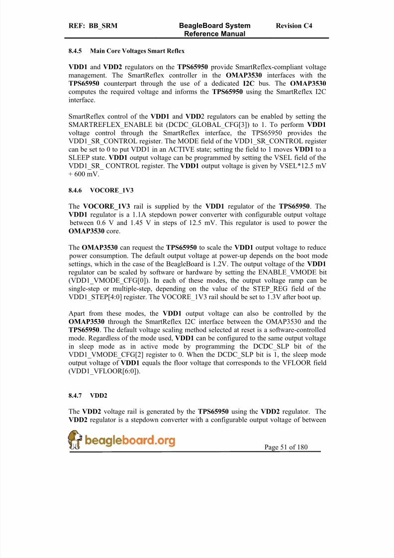
8/2/2019 Beagle Board Manual Rev. C4
http://slidepdf.com/reader/full/beagle-board-manual-rev-c4 51/180
REF: BB_SRM BeagleBoard SystemReference Manual
Revision C4
Page 51 of 180
8.4.5 Main Core Voltages Smart Reflex
VDD1 and VDD2 regulators on the TPS65950 provide SmartReflex-compliant voltagemanagement. The SmartReflex controller in the OMAP3530 interfaces with theTPS65950 counterpart through the use of a dedicated I2C bus. The OMAP3530
computes the required voltage and informs the TPS65950 using the SmartReflex I2Cinterface.
SmartReflex control of the VDD1 and VDD2 regulators can be enabled by setting theSMARTREFLEX_ENABLE bit (DCDC_GLOBAL_CFG[3]) to 1. To perform VDD1 voltage control through the SmartReflex interface, the TPS65950 provides theVDD1_SR_CONTROL register. The MODE field of the VDD1_SR_CONTROL register can be set to 0 to put VDD1 in an ACTIVE state; setting the field to 1 moves VDD1 to aSLEEP state. VDD1 output voltage can be programmed by setting the VSEL field of theVDD1_SR_ CONTROL register. The VDD1 output voltage is given by VSEL*12.5 mV+ 600 mV.
8.4.6 VOCORE_1V3
The VOCORE_1V3 rail is supplied by the VDD1 regulator of the TPS65950. TheVDD1 regulator is a 1.1A stepdown power converter with configurable output voltage between 0.6 V and 1.45 V in steps of 12.5 mV. This regulator is used to power theOMAP3530 core.
The OMAP3530 can request the TPS65950 to scale the VDD1 output voltage to reduce power consumption. The default output voltage at power-up depends on the boot modesettings, which in the case of the BeagleBoard is 1.2V. The output voltage of the VDD1
regulator can be scaled by software or hardware by setting the ENABLE_VMODE bit(VDD1_VMODE_CFG[0]). In each of these modes, the output voltage ramp can besingle-step or multiple-step, depending on the value of the STEP_REG field of theVDD1_STEP[4:0] register. The VOCORE_1V3 rail should be set to 1.3V after boot up.
Apart from these modes, the VDD1 output voltage can also be controlled by theOMAP3530 through the SmartReflex I2C interface between the OMAP3530 and theTPS65950. The default voltage scaling method selected at reset is a software-controlledmode. Regardless of the mode used, VDD1 can be configured to the same output voltagein sleep mode as in active mode by programming the DCDC_SLP bit of theVDD1_VMODE_CFG[2] register to 0. When the DCDC_SLP bit is 1, the sleep mode
output voltage of VDD1 equals the floor voltage that corresponds to the VFLOOR field(VDD1_VFLOOR[6:0]).
8.4.7 VDD2
The VDD2 voltage rail is generated by the TPS65950 using the VDD2 regulator. TheVDD2 regulator is a stepdown converter with a configurable output voltage of between

8/2/2019 Beagle Board Manual Rev. C4
http://slidepdf.com/reader/full/beagle-board-manual-rev-c4 52/180
REF: BB_SRM BeagleBoard SystemReference Manual
Revision C4
Page 52 of 180
0.6 V and 1.45 V and is used to power the OMAP3530 core. VDD2 differs from VDD1 in its current load capabilities with an output current rating of 600 mA in active mode.
The VDD2 provides different voltage regulation schemes. When VDD2 is controlled bythe VMODE2 signal or with the SmartReflex interface, the range of output voltage is 0.6
V to 1.45 V. The use of the VMODE2 signal and the VDD2_VMODE_CFG,VDD2_STEP, VDD2_FLOOR, and VDD2_ROOF registers is similar to the use of thecorresponding signals and registers for VDD1. VDD2 shares the same SmartReflex I2C bus to provide voltage regulation. The VDD2_SR_CONTROL register is provided for controlling the VDD2 output voltage in SmartReflex mode.
When the VDD2 is used in software-control mode, the VSEL (VDD2_ DEDICATED[4:0]) field can be programmed to provide output voltages of between 0.6V and 1.45 V. The output voltage for a given value of the VSEL field is given byVSEL*12.5 mV + 600 mV. If the VSEL field is programmed so that the output voltagecomputes to more than 1.45 V, the TPS65950 sets the VDD2 output voltage to 1.5 V.
8.5 Peripheral Voltages
There are six additional voltages used by the system that are generated by the TPS65950.These are:
o VDD_PLL2o VDD_PLL1o VDAC_1V8o VDD_SIMo VMMC1
o VAUX2
Figure 25 shows the peripheral voltages supplied by the TPS65950.
8.5.1 VDD_PLL2
This programmable LDO is used to power the OMAP3530 PLL circuitry. The VPLL2 LDO can be configured through the I2C interface to provide output voltage levels of 1.0V, 1.2 V, 1.3 V, or 1.8 V, based on the value of the VSEL field(VPLLI_DEDICATED[3:0]). On the board this rail is used to power DVI output for pins
DSS_DATA(0:5), DSS_DATA(10:15) and DSS_DATA(22:23). The VPLL2 must be setto 1.8V for proper operation of the DVI-D interface.
8.5.2 VDD_PLL1
The VPLL1 programmable LDO regulator is low-noise, linear regulator used for theOMAP3530 PLL supply. The VDD_PLL1 rail is initialized to 1.8V.
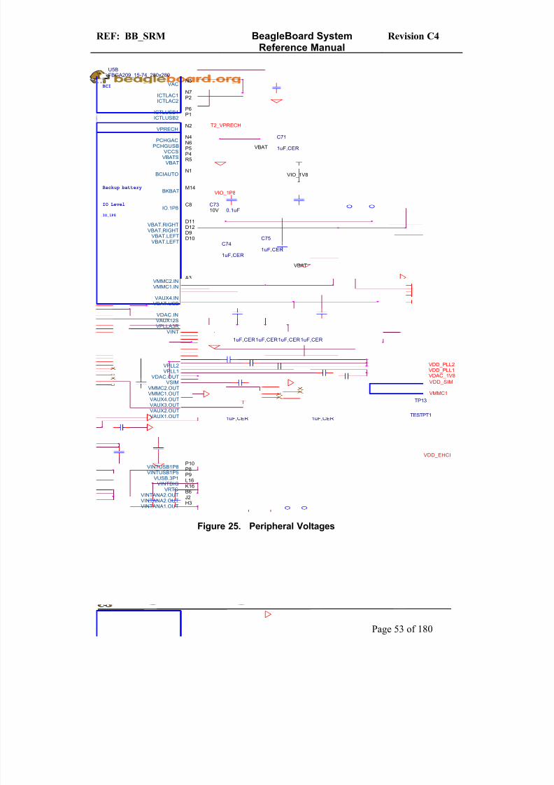
8/2/2019 Beagle Board Manual Rev. C4
http://slidepdf.com/reader/full/beagle-board-manual-rev-c4 53/180
REF: BB_SRM BeagleBoard SystemReference Manual
Revision C4
Page 53 of 180
VINTDIG
C90
1uF,CER
VDD_PLL2
VRTC
VDAC_1V8
VINTUSB1P5
VIO_1V8
VINTANA1.OUT
VMMC1
VINTUSB1P8
TP10
TESTPT1
C98 1uF,CER
C74
1uF,CER
VDD_SIM
C730.1uF10V
VINTANA2.OUTC96 1uF ,CER
VDD_PLL1
VUSB.3P1
VIO_1P8
C80
1uF,CER
C92 1uF,CER
TP11
TESTPT1
C100 1uF,CER
C75
1uF,CER
C91 1uF,CER 10V
C87
2.2uF,CER
C93 1uF,CER
C81
1uF,CER
VBAT
C94 1uF,CER
C82
1uF,CER
C79
1uF,CER TP9
TESTPT1
C88
1uF,CER
VBAT
C71
1uF,CER
T2_VPRECH
TP8
TESTPT1
IO Level
BCI
IO_1P8
Backup battery
U5BFBGA209_15-74_280x280
VBATR5
BKBATM14
ICTLAC2P2ICTLAC1N7
ICTLUSB2P1ICTLUSB1P6
BCIAUTON1
VPRECH N2
PCHGUSBN6
PCHGACN4
VBATSP4
VACN5
VCCSP5
VPLL2J15
VPLL1H14
VDAC.OUTL2
VINTUSB1P8P10
VINTUSB1P5P8
VRTCK16
VINTANA2.OUTB6
VINTDIGL16
VSIM
K2
VMMC2.OUT A4
VMMC1.OUTC2
VAUX4.OUTB3
VAUX3.OUTG16
VAUX2.OUTM3
VAUX1.OUTM2
VUSB.3P1P9
VBAT.RIGHTD11
VBAT.RIGHTD12
VDAC.INK1
VMMC2.INA3
VMMC1.INC1
VAUX4.INB2
VPLLA3RH15VAUX12SL1
VBAT.LEFTD10VBAT.LEFTD9
VBAT.USBR9
IO.1P8C8
VINTK15
VINTANA1.OUTH3VINTANA2.OUTJ2
C89
1uF,CER
TP13
TESTPT1
C86
1uF,CER
VDD_EHCI
Figure 25. Peripheral Voltages
8/2/2019 Beagle Board Manual Rev. C4
http://slidepdf.com/reader/full/beagle-board-manual-rev-c4 54/180
REF: BB_SRM BeagleBoard SystemReference Manual
Revision C4
Page 54 of 180
8.5.3 VDAC_1V8
The VDAC programmable LDO regulator is a high-PSRR, low-noise, linear regulator that powers the OMAP3530 dual-video DAC. It is controllable with registers via I2C andcan be powered down if needed. The VDAC LDO can be configured to provide 1.2V, 1.3
V, or 1.8 V in on power mode, based on the value of the VSEL field(VDAC_DEDICATED[3:0]). The VDAC_1V8 rail should be set to 1.8V for theBeagleBoard.
8.5.4 VDD_SIM
This voltage regulator is a programmable, low dropout, linear voltage regulator supplyingthe bottom 4 bits of the 8 bit SD/MMC card slot. The VSEL field(VSIM_DEDICATED[3:0]) can be programmed to provide output voltage of 1.0 V, 1.2V, 1.3 V, 1.8 V, 2.8 V, or 3.0 V and can deliver up to 50mA. The default output voltage
of this LDO as directed by the TPS65950 boot pins is 1.8V.
8.5.5 VMMC1
The VMMC1 LDO regulator is a programmable linear voltage converter that powers theMMC1 slot and includes a discharge resistor and overcurrent protection (short-circuit).This LDO regulator can also be turned off automatically when the MMC card extractionis detected. The VMMC1 LDO is powered from the main VBAT rail. The VMMC1 raildefaults to 3.0V as directed by the TPS65950 boot pins and will deliver up to 220mA. Itcan be set to 3.0V in the event 3V cards are being used.
8.5.6 VAUX2
The VAUX2 LDO regulator is a programmable linear voltage converter that powers the1.8V I/O rail of the USB PHY and includes a discharge resistor and overcurrent protection (short-circuit). The VAUX2 LDO is powered from the main VBAT rail. TheVMMC1 rail defaults to 3.0V as directed by the TPS65950 boot pins and will deliver upto 220mA. The voltage rail is labeled VDD_EHCI on the schematic.
8.5.7 Boot Configuration
The boot configuration pins on the TPS65950 determine the power sequence of the
device. For the OMAP3530 support, the boot pin configuration is fixed at:
o BOOT0 tied to VBATo BOOT1 tied to Ground.
8/2/2019 Beagle Board Manual Rev. C4
http://slidepdf.com/reader/full/beagle-board-manual-rev-c4 55/180
REF: BB_SRM BeagleBoard SystemReference Manual
Revision C4
Page 55 of 180
8.5.8 RTC Backup Battery
An optional battery to backup the Real Time Clock that is in the TPS65950. The boarddoes not come equipped with the battery. The battery can be purchased from DigiKey or other component suppliers. When the battery is not installed, R66 must be installed. You
must make sure that prior to installing the battery that R66 is removed.
Refer to section 9.11 for information on the battery selection and installation.

8/2/2019 Beagle Board Manual Rev. C4
http://slidepdf.com/reader/full/beagle-board-manual-rev-c4 56/180
REF: BB_SRM BeagleBoard SystemReference Manual
Revision C4
Page 56 of 180
8.5.9 Power Sequencing
Based on the boot configuration pins, the TPS65950 knows the type of OMAP processor that it needs to support, in this case the OMAP3530. The voltages are ramped in asequence that is compatible with the OMAP3530 processor. Figure 26 is the sequence in
which the power rails, clocks, and reset signal come up.
Figure 26. Power Sequencing

8/2/2019 Beagle Board Manual Rev. C4
http://slidepdf.com/reader/full/beagle-board-manual-rev-c4 57/180
REF: BB_SRM BeagleBoard SystemReference Manual
Revision C4
Page 57 of 180
8.5.10 Reset Signals
The BeagleBoard uses three distinct reset circuits:
o Warm Reset
o Cold Reseto User Reset
Figure 27 shows the connections for the Reset interfaces.
Figure 27. Reset Circuitry
8.5.10.1 Warm Reset
The warm reset is generated by the OMAP3530 processor on power up. ThenRESWARM signal is a bidirectional reset. When an internal reset occurs,nRESWARM goes low and resets all the peripherals and the TPS65950. The TPS65950 can be configured to perform a warm reset of the device to bring it into a known definedstate by detecting a request for a warm reset on the NRESWARM pin. The minimumduration of the pulse on the nRESWARM pin should be two 32-kHz clock cycles. ThenRESWARM output is open-drain; consequently, an external pullup resistor is required.There is no way for the user to generate a warm reset on the BeagleBoard.
8.5.10.2 Cold Reset
On power up as shown in Figure 27, the TPS65950 generates nRESPWRON, power onreset. The signal from the TPS65950 is an output only and is not an open drain signal.By running the signal through a buffer, SN74LVC2G07, the signal becomes open drain,which requires a pullup on the signal. This will allow the nRESPWRON signal to be
J3 2 4 6 8
10 12 14 16 18 20 22 24 26 28
135791113151719
21232527
R474.7K VIO_1V8
U4A
SN74LVC2G07DCKR
1
2
5
6
VBAT IO_1P8
T
P
S
6
5
95
0
U5A
B13 A13 A11
nRESWARMnRESPWRON
PWRON
nRESPWRON
VIO_1V8
R3710K
C8
0.1uF
VBAT
PWRON
R45 4.7K
S2
B3F-1000 1 3
2 4
R53DNI
nRESWARM VIO_1V8 OMAP3
U3B OMAP3530_ES3.0
AH25 AF24 SYS_nRESPWRON
SYS_nRESWARM/GPIO_30
nRESET

8/2/2019 Beagle Board Manual Rev. C4
http://slidepdf.com/reader/full/beagle-board-manual-rev-c4 58/180
REF: BB_SRM BeagleBoard SystemReference Manual
Revision C4
Page 58 of 180
pulled low, by pressing the reset switch S2, to force a reset to the OMAP3530 processor and to any device on the expansion card that require a reset.It also allows for the reset signal to be pulled low or held low for an extended time bycircuitry on the expansion card if needed.
8.5.10.3 User Reset
The USER RESET button can be used to request a Warm Reset from the processor. After initialization, this pin becomes an input to the processor. By pushing the Reset button, aninterrupt is generated into the OMAP3530 processor. The software that is run as a resultof this can then do whatever housekeeping is required and then send the processor into areset mode.
8.5.10.4 PWRON
You will notice another signal on the TPS65950 called PWRON. This signal isreferenced in the TPS65950 documentation. In the BeagleBoard design it is not used butit is pulled high to insure the desired operation is maintained.
8.5.11 mSecure Signal
This signal provides for protection of the RTC registers in the TPS65950 be disablingthat function via a control signal form the OMAP3530 processor.
For more information on the operation on the signal, please refer to the OMAP3530Technical Reference Manual.

8/2/2019 Beagle Board Manual Rev. C4
http://slidepdf.com/reader/full/beagle-board-manual-rev-c4 59/180

8/2/2019 Beagle Board Manual Rev. C4
http://slidepdf.com/reader/full/beagle-board-manual-rev-c4 60/180
REF: BB_SRM BeagleBoard SystemReference Manual
Revision C4
Page 60 of 180
o Linuxo QNXo Symbiano Others
This OMAP3530 device includes state-of-the-art power-management techniques requiredfor high-performance low power products. The OMAP3530 supports the followingfunctions and interfaces on the BeagleBoard:
o Microprocessor unit (MPU) subsystem based on the ARM Cortex-A8™microprocessor
o POP Memory interfaceo 2Gb MDDR (256Mbytes)o 2Gb NAND Flash (256Mbytes)
o 24 Bit RGB Display interface (DSS)o SD/MMC interface
o USB OTG interfaceo NTSC/PAL/S-Video outputo Power managemento Serial interfaceo I2C interfaceo I2S Audio interface (McBSP2)o Expansion McBSP1o JTAG debugging interface
8.6.2 SDRAM Bus
The SDRAM bus is not accessible on the BeagleBoard. Its connectivity is limited to thePOP memory access on the top of the OMAP3530 and therefore is only accessible by theSDRAM memory.
The base address for the DDR SDRAM in the POP device is 0x8000 0000.
8.6.3 GPMC Bus
The GPMC bus is not accessible on the BeagleBoard. Its connectivity is limited to the
POP memory access on the top of the OMAP3530 and therefore is only accessible by the NAND memory.
The memory on the GPMC bus is NAND and therefore will support the classical NANDinterface. The address of the memory space is programmable.

8/2/2019 Beagle Board Manual Rev. C4
http://slidepdf.com/reader/full/beagle-board-manual-rev-c4 61/180
REF: BB_SRM BeagleBoard SystemReference Manual
Revision C4
Page 61 of 180
8.6.4 DSS Bus
The display subsystem provides the logic to display a video frame from the memoryframe buffer in SDRAM onto a liquid-crystal display (LCD) display via the DVI-D
interface or to a standalone LCD panel via the LCD interface connectors. The logic levelsof the LCD expansion connectors are 1.8V so it will require buffering of the signals todrive most LCD panels. The DSS is configured to a maximum of 24 bits, but can be usedin lower bit modes if needed.
8.6.5 McBSP2
The multi-channel buffered serial port (McBSP) McBSP2 provides a full-duplex directserial interface between the OMAP3530 and the audio CODEC in the TPS65950 usingthe I2S format. Only four signals are supported on the McBSP2 port. Figure 29 is adepiction of McBSP2.
Figure 29. McBSP2 Interface
8.6.6 McBSP1
McBSP1 provides a full-duplex direct serial interface between the OMAP3530 and theexpansion interface. There are 6 signals supported on McBSP1, unlike the 4 signals onthe other ports. Figure 30 is a diagram of McBSP1.

8/2/2019 Beagle Board Manual Rev. C4
http://slidepdf.com/reader/full/beagle-board-manual-rev-c4 62/180
REF: BB_SRM BeagleBoard SystemReference Manual
Revision C4
Page 62 of 180
Figure 30. McBSP1 Interface
8.6.7 McBSP3
McBSP3 provides a full-duplex direct serial interface between the OMAP3530 and theexpansion interface. Figure 31 is a diagram of McBSP3.
Figure 31. McBSP3 Interface
8.6.8 Pin Muxing
On the OMAP3530, the majority of pins have multiple configurations that the pin can beset to. In essence, the pin can become different signals depending on how they are set inthe software. In order for the BeagleBoard to operate, the pins used must be set to thecorrect signal. In some cases, the default signal is the correct signal. Each pin can have amaximum of 8 options on the pin. This is called the pin mode and is indicated by a three

8/2/2019 Beagle Board Manual Rev. C4
http://slidepdf.com/reader/full/beagle-board-manual-rev-c4 63/180
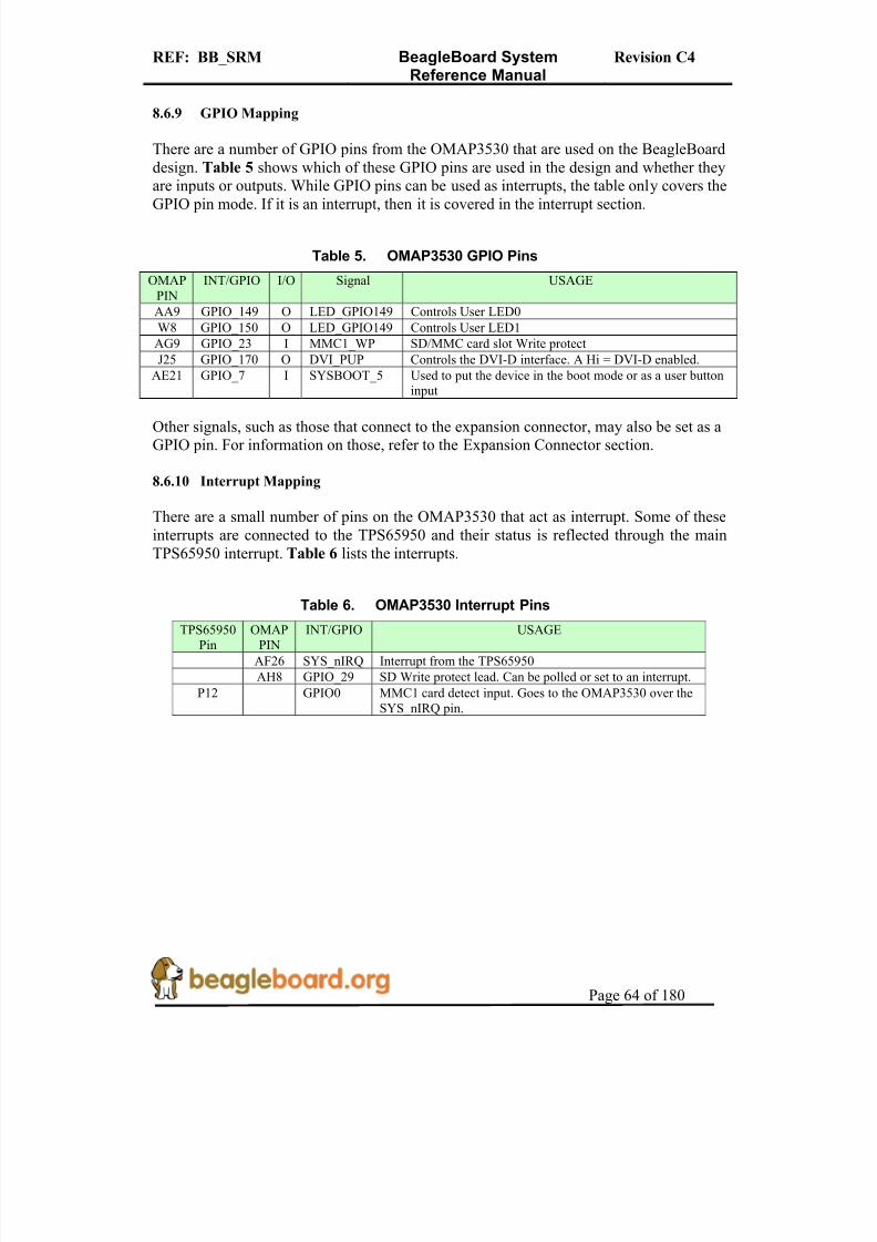
8/2/2019 Beagle Board Manual Rev. C4
http://slidepdf.com/reader/full/beagle-board-manual-rev-c4 64/180
REF: BB_SRM BeagleBoard SystemReference Manual
Revision C4
Page 64 of 180
8.6.9 GPIO Mapping
There are a number of GPIO pins from the OMAP3530 that are used on the BeagleBoarddesign. Table 5 shows which of these GPIO pins are used in the design and whether theyare inputs or outputs. While GPIO pins can be used as interrupts, the table only covers the
GPIO pin mode. If it is an interrupt, then it is covered in the interrupt section.
Table 5. OMAP3530 GPIO Pins
OMAPPIN
INT/GPIO I/O Signal USAGE
AA9 GPIO_149 O LED_GPIO149 Controls User LED0
W8 GPIO_150 O LED_GPIO149 Controls User LED1
AG9 GPIO_23 I MMC1_WP SD/MMC card slot Write protect
J25 GPIO_170 O DVI_PUP Controls the DVI-D interface. A Hi = DVI-D enabled.
AE21 GPIO_7 I SYSBOOT_5 Used to put the device in the boot mode or as a user buttoninput
Other signals, such as those that connect to the expansion connector, may also be set as aGPIO pin. For information on those, refer to the Expansion Connector section.
8.6.10 Interrupt Mapping
There are a small number of pins on the OMAP3530 that act as interrupt. Some of theseinterrupts are connected to the TPS65950 and their status is reflected through the mainTPS65950 interrupt. Table 6 lists the interrupts.
Table 6. OMAP3530 Interrupt PinsTPS65950
PinOMAP
PININT/GPIO USAGE
AF26 SYS_nIRQ Interrupt from the TPS65950
AH8 GPIO_29 SD Write protect lead. Can be polled or set to an interrupt.
P12 GPIO0 MMC1 card detect input. Goes to the OMAP3530 over theSYS_nIRQ pin.

8/2/2019 Beagle Board Manual Rev. C4
http://slidepdf.com/reader/full/beagle-board-manual-rev-c4 65/180

8/2/2019 Beagle Board Manual Rev. C4
http://slidepdf.com/reader/full/beagle-board-manual-rev-c4 66/180

8/2/2019 Beagle Board Manual Rev. C4
http://slidepdf.com/reader/full/beagle-board-manual-rev-c4 67/180
REF: BB_SRM BeagleBoard SystemReference Manual
Revision C4
Page 67 of 180
8.9 USB OTG Port
The BeagleBoard has a USB OTG (On-the-Go) port. It can be used as an OTG port,Client port, or Host port. The main use is as a client port, as that is the mode that willsupply the power needed to power the BeagleBoard.
8.9.1 USB OTG Overview
USB OTG is a supplement to the USB 2.0 specification. The standard USB uses amaster/slave architecture, a USB host acting as a master and a USB peripheral acting as a
slave. Only the USB host can schedule the configuration and data transfers over the link.The USB peripherals cannot initiate data transfers, they only respond to instructionsgiven by a host.
USB OTG works differently in that gadgets don't need to be pure peripherals becausethey can sometimes act as hosts. An example might be connecting a USB keyboard or printer to BeagleBoard or a USB printer that knows how to grab documents from certain peripherals and print them. The USB OTG compatible devices are able to initiate thesession, control the connection and exchange Host/Peripheral roles between each other.
The USB OTG supplement does not prevent the use of a hub, but it describes role
swapping only in the case of a one-to-one connection where two OTG devices aredirectly connected. If a standard hub is used, the supplement notes that using it will leadto losing USB OTG role-swap capabilities making one device as the Default-Host and theother as the Default-Peripheral until the hub is disconnected.
The combination of the OMAP3530 and the TPS65950 allows the BeagleBoard to work as an OTG device if desired. The primary mode of operation however, is intended to be aclient mode in order to pull power from the USB host which is typically a PC. As the RevB does not have a Host USB port, this port will be used as a Host port in manyapplications.
NOTE: In order to use the OTG in the Host mode, the
BeagleBoard must be powered from the DC supply.
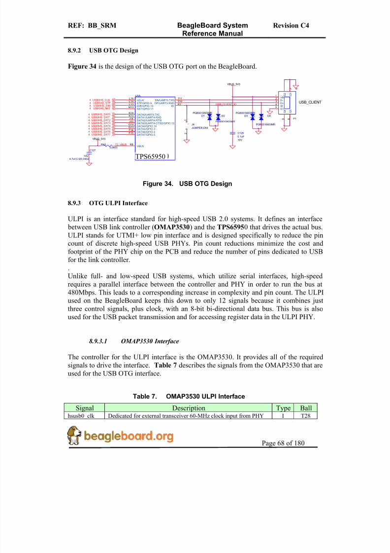
8/2/2019 Beagle Board Manual Rev. C4
http://slidepdf.com/reader/full/beagle-board-manual-rev-c4 68/180
REF: BB_SRM BeagleBoard SystemReference Manual
Revision C4
Page 68 of 180
8.9.2 USB OTG Design
Figure 34 is the design of the USB OTG port on the BeagleBoard.
USB0HS_DAT34USB0HS_DAT24
USB0HS_DIR4
+
J6
JUMPER,DNI
1
2
USB0HS_STP4
VBUS_5V0
D3PGB0010603MR
T2_VBUS
C127
4.7uf,C ER,040210V
USB0HS_DAT44
D4
PGB0010603MR
D1PGB0010603MR
USB_CLIENT
USB0HS_DAT14
USB0HS_DAT54
USB0HS_NXT4
P1
23
1
4
7 6
5
8 9
D-D+
VB
ID
G 2
G 3
G1
G 5
G 4
C129
0.1uF
10V
USB0HS_CLK4
TWL4030
U5A
R8
T10T11
R11
L15L14L13M13
K14K13J14J13
F13F14
G14G13
VBUS
DP/UART3.RXDDN/UART3.TXD
ID
UCLKSTP/GPIO.9DIR/GPIO.10NXT/GPIO.11
DATA0/UART4.TXDDATA1/UART4.RXDDATA2/UART4.RTSIDATA3/UART4.CTSO/GPIO.12
DATA7/GPIO.5DATA6/GPIO.4
DATA4/GPIO.14DATA5/GPIO.3
USB0HS_DAT04D2
PGB0010603MR
R430,0603
USB0HS_DAT74
VBUS_5V0
USB0HS_DAT64
USB_CLIENT_ID
Figure 34. USB OTG Design
8.9.3 OTG ULPI Interface
ULPI is an interface standard for high-speed USB 2.0 systems. It defines an interface between USB link controller (OMAP3530) and the TPS65950 that drives the actual bus.ULPI stands for UTMI+ low pin interface and is designed specifically to reduce the pincount of discrete high-speed USB PHYs. Pin count reductions minimize the cost andfootprint of the PHY chip on the PCB and reduce the number of pins dedicated to USBfor the link controller.
.Unlike full- and low-speed USB systems, which utilize serial interfaces, high-speedrequires a parallel interface between the controller and PHY in order to run the bus at480Mbps. This leads to a corresponding increase in complexity and pin count. The ULPIused on the BeagleBoard keeps this down to only 12 signals because it combines justthree control signals, plus clock, with an 8-bit bi-directional data bus. This bus is alsoused for the USB packet transmission and for accessing register data in the ULPI PHY.
8.9.3.1 OMAP3530 Interface
The controller for the ULPI interface is the OMAP3530. It provides all of the requiredsignals to drive the interface. Table 7 describes the signals from the OMAP3530 that areused for the USB OTG interface.
Table 7. OMAP3530 ULPI Interface
Signal Description Type Ballhsusb0_clk Dedicated for external transceiver 60-MHz clock input from PHY I T28
TPS65950

8/2/2019 Beagle Board Manual Rev. C4
http://slidepdf.com/reader/full/beagle-board-manual-rev-c4 69/180
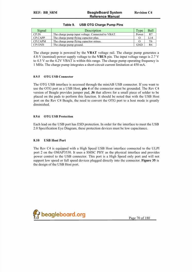
8/2/2019 Beagle Board Manual Rev. C4
http://slidepdf.com/reader/full/beagle-board-manual-rev-c4 70/180

8/2/2019 Beagle Board Manual Rev. C4
http://slidepdf.com/reader/full/beagle-board-manual-rev-c4 71/180
REF: BB_SRM BeagleBoard SystemReference Manual
Revision C4
Page 71 of 180
U7
USB3322 (CSP)
STP A3
DIR A4
NXTB5
CLKOUT A5
DATA0B4
DATA1C5
DATA2C4
DATA3D5
DATA4D4
DATA5E5
DATA6E4
DATA7D3
VBUS C2
DMD1
DPE1
IDB1
VDD3.3D2
VDD1.8B3
VBATC1
RBIASA1
GNDC3
RESETBB2
REFCLK A2
U6
TPS2061 (DGN)
GND1
IN2
IN3
EN4
OUT6
OUT7OUT8
OC5
PAD9
R 1 1 1
1 0 K
R528.064k
C104
22uF,CER,0805
R49
10K
+C101100uf, 6.3V16V
Power Control
USB33_ID
TP20
TESTPT1
R69
0,0603
C102
4.7uf,CER,040210V
R510
C105
0.1uF10V
C103
0.1uF10V
C106
4.7uf,C ER,040210V
R 50 10K ,06 03
SHIELD
SHIELD
VBUS
D-
D+
GND
P7USB-A Conn. - 87520-xx1xx
1
32
4
5
6
C107
0.1uF10V
VBAT
VBAT
DC_5V
VDD_EHCI
USB2HS_CLK4
VIO_1V8
USB2HS_STP4USB2HS_DIR4USB2HS_NXT4
USB2HS_DAT04
nEN_USB_PWR6
USB2HS_DAT24USB2HS_DAT14
USB2HS_DAT34
USB2HS_DAT54USB2HS_DAT44
USB2HS_DAT64
HOST_nOC 6
USB2HS_DAT74
USB2HS_nRST4
USB33_VBUS
USB33_VDD3.3
USB33_RBIAS
USB HOST INTERFACE
Host Connector
HOST_D-HOST_D+
VDD1.8
R680,0603,DNI
VDD1.8
R67
30MHZ_50mA1 2
HOST_VBUS
Figure 35. USB Host Design
8.10.1 Host USB OMAP3 Interface
The interface to the OMAP3 is the HSUSB2 interface. The signals used on this interfaceare contained in Table 10.
Table 10. USB Host Port OMAP Signals
Signal Description Input/Output
Hsusb2_clk External transceiver 60-MHz clock output to PHY O
Hsusb2_stp External transceiver Stop signal O
Hsusb2_dir Transceiver data direction control from PHY I
Hsusb2_nxt Next signal from PHY I
Hsusb2_data0 Bidirectional data bus signal for 12-pin ULPI operation I/O
Hsusb2_data1 Bidirectional data bus signal for 12-pin ULPI operation I/O
Hsusb2_data2 Bidirectional data bus signal for 12-pin ULPI operation I/O
Hsusb2_data3 Bidirectional data bus signal for 12-pin ULPI operation I/O
Hsusb2_data4 Bidirectional data bus signal for 12-pin ULPI operation I/O
Hsusb2_data5 Bidirectional data bus signal for 12-pin ULPI operation I/O
Hsusb2_data6 Bidirectional data bus signal for 12-pin ULPI operation I/O
Hsusb2_data7 Bidirectional data bus signal for 12-pin ULPI operation I/O
Gpio_147 Enable/reset line to the USB PHY. O
The husb2_clk signal is an output only and is used to support a HS USB PHY thatsupports an input clock mode. The SMSC PHY device supports this mode and is used onthe Beagle.
8.10.2 Host USB PHY
The PHY used in the design is a USB3322/26 series device from SMSC. The USB3322 isa highly integrated Hi-Speed USB2.0 Transceiver (PHY) that meets all of the electrical
8/2/2019 Beagle Board Manual Rev. C4
http://slidepdf.com/reader/full/beagle-board-manual-rev-c4 72/180
REF: BB_SRM BeagleBoard SystemReference Manual
Revision C4
Page 72 of 180
requirements to be used as a Hi-Speed USB Host, Device, or an On-the-Go (OTG)transceiver. In this design, only the host mode of operation is being supported. TheUSB3322 uses the industry standard UTMI+ Low Pin Interface (ULPI) to connect theUSB PHY to the OMAP3. ULPI uses a method of in-band signaling and status bytetransfers between the Link and PHY to facilitate a USB session with only 12 pins.
In order to interface to the OMAP3530, the device must be used in the 60MHz clock mode. This is done by tying the CLKOUT signal on the USB PHY to VIO_1V8. On RevC4, a zero ohm series resistor was added. This is not required, but was added as a “just incase” option if the CLKOUT signal was a source of noise in the PHY. It was proven notto be the case. The clock for the PHY is derived from the 60MHz signal generated by theOMAP3530. All of the signals and their functions align with the descriptions found inthe OMAP3530 interface section.
The USB3322 device requires two voltages, the VIO_1V8 rail to power the I/O rails andthe VBAT, which needs to be between 3.1V and 5.1V, to power the rest of the device. On
the board the VBAT is a regulated 4.2V DC. The 3.3V rail for the device is generatedinternally and requires a filter and bypass cap to be connected externally. Unlike the RevC3 version, the Rev C4 version derives its 1.8V from the VAUX2 rail supplied by theTPS65950 PMIC. It also uses a ferrite bead, R67, to provide additional filtering for noise.This is the fix for the EHCI noise issue. There is an option to connect the 1.8V rail to theVIO_1V8 rail, but that has not been populated in the Rev C4 design.
The RBIAS block in the PHY consists of an internal bandgap reference circuit used for generating the driver current and the biasing of the analog circuits. This block requires anexternal 8.06K Ω, 1% tolerance, reference resistor connected from RBIAS to ground. Thenominal voltage at RBIAS is 0.8V and therefore the resistor will dissipate approximately
80µW of power.
The USB3322 can detect ID grounded and ID floating to determine if an A or B cablehas been inserted. The A plug will ground the ID pin while the B plug will float the ID
pin. As we are not using this device to support the OTG protocol but instead as a hostdevice, we ground the ID pin to force it into a Host mode at all times. The ID signal isnot present on the USB connector.
The USB3322 transceiver fully integrates all of the USB termination resistors on both DP
and DM. This includes 1.5k Ω pull-up resistors, 15k Ω pull-down resistors and the 45Ω high speed termination resistors. These resistors require no tuning or trimming.
8.10.3 Host USB Connector
The USB connector used is a Type A receptacle and provides connections for four signals, DP, DM, VBUS, and Ground. This is the same connector you will see on the back of a USB hub. You will notice that there are no external ESD devices on theconnector. The ESD protection is integrated into the USB PHY.

8/2/2019 Beagle Board Manual Rev. C4
http://slidepdf.com/reader/full/beagle-board-manual-rev-c4 73/180
REF: BB_SRM BeagleBoard SystemReference Manual
Revision C4
Page 73 of 180
8.10.4 Host USB Power Control
Power is provided through the USB Host connector to power devices that are pluggedinto the USB host connector. This power can be controlled by the OMAP3530 via theTPS2061 power switch.
The TPS2061 power-distribution switch is intended for applications where heavycapacitive loads and short-circuits are likely to be encountered. This device incorporatesa 70-mW N-channel MOSFET power switch. Gate drive is provided by an internalcharge pump designed to control the power-switch rise times and fall times to minimizecurrent surges during switching. The switch is controlled by the TPS65950 using theLED.A signal. The OMAP3530 uses the I2C interface to activate the signal in theTPS65950.
The amount of available current to be supplied depends on the remaining currentavailable when in USB mode or the DC supply. The switch will not be able to supply
more current than is available from the DC source being used.
The TPS2061 also provides an overcurrent indicator and protection circuit. When theoutput load exceeds the current-limit threshold or a short is present, the device limits theoutput current to a safe level by switching into a constant-current mode, pulling theovercurrent (OC) logic output low. This is read by the TPS65950 via the CD2 pin. TheCD2 pin can be set to generate an interrupt to the OMAP3530 to alert it of this condition.
When continuous heavy overloads and short-circuits increase the power dissipation in theswitch, causing the junction temperature to rise, a thermal protection circuit shuts off theswitch to prevent damage. Recovery from a thermal shutdown is automatic once the
device has cooled sufficiently. Internal circuitry ensures that the switch remains off untilvalid input voltage is present. This power-distribution switch is designed to set currentlimit at 1.5 A typically. As mentioned, the amount of current available depends on thecurrent source.
8.11 SD/MMC
The board provides an SD/MMC interface. Its primary use is for proving the boot sourcefor SW but it can be used for other things such as cameras and Wireless LAN cards.Typical users prefer to use the USB port for these functions and as such, the SD cardfunction is the primary us of this connector.
The connector supports 7 different types of cards.
o SD- Secure Digital (SD) is a flash memory card format developed by Matsushita,SanDisk and Toshiba for use in portable devices. As of 2007, SD card capacitiesrange from 8 MB to 16 GB. Several companies have announced SD cards with 32GB. Cards with 4-32 GB are considered high-capacity. The format has proven to be very popular. However, compatibility issues between older devices and the

8/2/2019 Beagle Board Manual Rev. C4
http://slidepdf.com/reader/full/beagle-board-manual-rev-c4 74/180

8/2/2019 Beagle Board Manual Rev. C4
http://slidepdf.com/reader/full/beagle-board-manual-rev-c4 75/180
REF: BB_SRM BeagleBoard SystemReference Manual
Revision C4
Page 75 of 180
24 mm x 32 mm x 1.4 mm. MMC originally used a 1-bit serial interface, butnewer versions of the specification allow transfers of 4 at a time. MMCs arecurrently available in sizes up to and including 4 GB an 8 GB models.
o MMCplus- The version 4.x of the MMC standard, introduced in 2005, brought in
two very significant changes to compete against SD cards. These were support for running at higher speeds (26MHz, 52MHz) than the original MMC (20MHz) or SD (25MHz, 50MHz). Version 4.x cards are fully backward compatible withexisting readers but require updated hardware/software to use their newcapabilities; even though the 4 bit wide bus and high-speed modes of operationare deliberately electrically compatible with SD, the initialization protocol isdifferent, so firmware/software updates are required to allow these features to beenabled when the card is used in an SD reader.
o MMCmobile – Is basically the same as MMCplus except that it supports 8 bitdata mode.
o RS-MMC –This alternate form factor is known as Reduced-SizeMultiMediaCard, or RS-MMC, and was introduced in 2004. This form factor is asmaller form factor, of about half the size: 24 mm × 18 mm × 1.4 mm. RS-MMCsare simply smaller MMCs. RS-MMCs are currently available in sizes up to andincluding 4 GB. Nokia used to use RS-MMC in the Nokia 770 Internet Tablet.Figure 37 is a side by side comparison of the RS-MMC and MMC card.
Figure 37. RS-MMC and Card
Figure 38 is the SD/MMC interface design on the BeagleBoard.
8.11.1 MMC Power
The SD/MMC connector is supplied power from the TPS65950 using the VMMC1 rail.The default setting on this rail is 3.0V as set by the Boot ROM and under SW control, can be set to 1.80V for use with 1.8V cards. The maximum current this rail can provide is

8/2/2019 Beagle Board Manual Rev. C4
http://slidepdf.com/reader/full/beagle-board-manual-rev-c4 76/180

8/2/2019 Beagle Board Manual Rev. C4
http://slidepdf.com/reader/full/beagle-board-manual-rev-c4 77/180
REF: BB_SRM BeagleBoard SystemReference Manual
Revision C4
Page 77 of 180
TWL4030
U3B
VMMC1.OUTC2
CD1P12
C93
0.1uF10V
P2MHC-W21-601
#1_MMC+/MMCM/RSMMC/MMC/SD1
#2_MMC+/MMCM/RSMMC/MMC/SD2
#3_MMC+/MMCM/RSMMC/MMC/SD3
#4_MMC+/MMCM/RSMMC/MMC/SD4
#5_MMC+/MMCM/RSMMC/MMC/SD5
#6_MMC+/MMCM/RSMMC/MMC/SD6
#7_MMC+/MMCM/RSMMC/MMC/SD7
#8_MMC+/MMCM/SD8
SD_WP14
CD15
GND127
GND228
#10_MMC+/MMCM10
#1_miniSD16
#2_miniSD17
#3_miniSD18
#4_miniSD19
#5_miniSD
20
#6_miniSD21
#7_miniSD22
#8_miniSD23
#9_miniSD24
#10_miniSD25
#11_miniSD26
#9_MMC+/MMCM/SD9
#11_MMC+/MMCM11
#12_MMC+/MMCM12
#13_MMC+/MMCM13
R 5
1 0 K
VIO_1V8
R 1 6
1 0 K
C3
0.1uF10V
SD/MMC Connector 6 in 1
MMC+, MMCMobile, SD,
MMC, miniSD, RS-MMC
VMMC1
+C2
10UF
R 1 5
1 0 K
R 3 6
1 0 K
R 1 1
1 0 K R
1 7
1 0 K
R 1 8
1 0 K
R 1 2
1 0 K
O M A P 3 5 x x
U2A
OMAP35xx_ES2.0
MMC1_CLKN28
MMC1_CMDM27
MMC1_DAT0N27
MMC1_DAT1N26
MMC1_DAT2N25
MMC1_DAT3P28
MMC1_DAT4P27
MMC1_DAT5P26
MMC1_DAT6R27
MMC1_DAT7R25
GPIO_23AG9
R10 33
Figure 38. SD/MMC Interface
The known limitations are as follows:
o No built-in hardware support for error correction codes (ECC). See the Multimedia Card System Specification, v4.0, and the SD Memory Card
Specifications, v1.10d, for details about ECC.o The maximum block size defined in the SD Memory Card Specifications, v1.10d
that the host driver can read and write to the buffer in the host controller is 2048 bytes. MMC supports a maximum block size of 1024 bytes. Up to 512 bytetransfers, the buffer in MMC is considered as a double buffering with ping-pongmanagement; half of the buffer can be written while the other part is read. For 512to 1024 byte transfers, the entire buffer is dedicated to the transfer (read only or
write only).
Table 11 provides a description of the signals on the MMC card.

8/2/2019 Beagle Board Manual Rev. C4
http://slidepdf.com/reader/full/beagle-board-manual-rev-c4 78/180
REF: BB_SRM BeagleBoard SystemReference Manual
Revision C4
Page 78 of 180
Table 11. SD/MMC OMAP Signals
Signal Name Description I/O PinMMC1_CLK SD/MMC Clock output. O N28
MMC1_CMD SD/MMC Command pin I/O M27
MMC1_DAT(0..7) SD/MMC Data pins I/O N27,N26,N25,P28,P27,
P26,R27,R25MMC_WP Write Protect detect I AG9
8.11.3 Card Detect
When a card is inserted into the SD/MMC connector, the Card Detect pin is grounded.This is detected on pin P12 of the TPS65950. An interrupt, if enabled, is sent to theOMAP3530 via the interrupt pin. The SW can be written such that the system comes outof sleep or a reduced frequency mode when the card is detected.
8.11.4 Write Protect
If an SD card is inserted into the SD/MMC connector and the write protect pin is active,the Write Detect pin is grounded. This is detected GPIO_29 of the OMAP3530. The SWcan then determine if the card is write protected and act accordingly.
8.11.5 8 Bit Mode
The BeagleBoard also supports the new 8-bit cards. The upper 4 bits are supplied by theVDD_SIM power rail and as such the 8-bit mode is only supported in 1.8V modes. Thisrequires that both the VMMC1 and VDD_SIM rails must be set to 1.8V when using 8 bitcards.
8.11.6 Booting From SD/MMC Cards
The ROM code supports booting from MMC and SD cards with some limitations:
o Support for MMC/SD cards compliant with the Multimedia Card SystemSpecification v4.2 from the MMCA Technical Committee and the Secure DigitalI/O Card Specification v2.0 from the SD Association. Including high-capacity
(size >2GB) cards: HC-SD and HC MMC.o 3-V power supply, 3-V I/O voltage on port 1o Initial 1-bit MMC mode, 4-bit SD mode.o Clock frequency:
– Identification mode: 400 kHz – Data transfer mode: 20 MHz
o Only one card connected to the buso FAT12/16/32 support, with or without master boot sector (MBR).
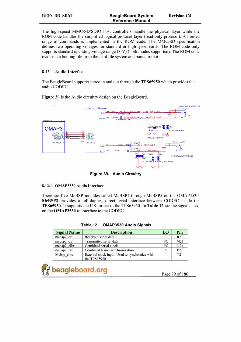
8/2/2019 Beagle Board Manual Rev. C4
http://slidepdf.com/reader/full/beagle-board-manual-rev-c4 79/180

8/2/2019 Beagle Board Manual Rev. C4
http://slidepdf.com/reader/full/beagle-board-manual-rev-c4 80/180

8/2/2019 Beagle Board Manual Rev. C4
http://slidepdf.com/reader/full/beagle-board-manual-rev-c4 81/180

8/2/2019 Beagle Board Manual Rev. C4
http://slidepdf.com/reader/full/beagle-board-manual-rev-c4 82/180
REF: BB_SRM BeagleBoard SystemReference Manual
Revision C4
Page 82 of 180
Table 14. OMAP3530 LCD Signals
Signal Name Description Type Balldss_pclk LCD Pixel Clock O D28
dss_hsync LCD Horizontal Synchronization O D26
dss_vsync LCD Vertical Synchronization O D27
dss_acbias Pixel data enable (TFT) output O E27dss_data0 LCD Pixel Data bit 0 BLUE0 O AG22
dss_data1 LCD Pixel Data bit 1 BLUE1 O AH22
dss_data2 LCD Pixel Data bit 2 BLUE2 O AG23
dss_data3 LCD Pixel Data bit 3 BLUE3 O AH23
dss_data4 LCD Pixel Data bit 4 BLUE4 O AG24
dss_data5 LCD Pixel Data bit 5 BLUE5 O AH24
dss_data6 LCD Pixel Data bit 6 BLUE6 O E26
dss_data7 LCD Pixel Data bit 7 BLUE7 O F28
dss_data8 LCD Pixel Data bit 8 GREEN0 O F27
dss_data9 LCD Pixel Data bit 9 GREEN1 O G26
dss_data10 LCD Pixel Data bit 10 GREEN2 O AD28
dss_data11 LCD Pixel Data bit 11 GREEN3 O AD27
dss_data12 LCD Pixel Data bit 12 GREEN4 O AB28
dss_data13 LCD Pixel Data bit 13 GREEN5 O AB2
dss_data14 LCD Pixel Data bit 14 GREEN6 O AA28
dss_data15 LCD Pixel Data bit 15 GREEN7 O AA27
dss_data16 LCD Pixel Data bit 16 RED0 O G25
dss_data17 LCD Pixel Data bit 17 RED1 O H27
dss_data18 LCD Pixel Data bit 18 RED2 O H26
dss_data19 LCD Pixel Data bit 19 RED3 O H25
dss_data20 LCD Pixel Data bit 20 RED4 O E28
dss_data21 LCD Pixel Data bit 21 RED5 O J26
dss_data22 LCD Pixel Data bit 22 RED6 O AC27
dss_data23 LCD Pixel Data bit 23 RED7 O AC28
GPIO_170 Powers down the TFP410 when Lo. TFP410 is activewhen Hi. O J25
I2C3_SCL I2C3 clock line. Used to communicate with the monitor to determine setting information.
I/O AF14
I2C3_SDA I2C3 data line. Used to communicate with the monitor to determine setting information.
I/O AG14
10ohm series resistors are provide in the signal path to minimize reflections in the highfrequency signals from the OMAP3530 to the TFP410. These resistors are in the form of resistor packs on the BeagleBoard. The maximum clock frequency of these signals is65MHz.
8.13.2 OMAP3530 LCD Power
In order for the DSS outputs to operate correctly out of the OMAP3530, two voltage railsmust be active, VIO_1V8 and VDD_PLL2. Both of these rails are controlled by theTPS65950 and must be set to 1.8V. By default, VDD_PLL2 is not turned and must beactivated by SW. Otherwise some of the bits will not have power supplied to them.

8/2/2019 Beagle Board Manual Rev. C4
http://slidepdf.com/reader/full/beagle-board-manual-rev-c4 83/180
REF: BB_SRM BeagleBoard SystemReference Manual
Revision C4
Page 83 of 180
8.13.3 TFP410 Framer
The TFP410 provides a universal interface to allow a glue-less connection to provide theDVI-D digital interface to drive external LCD panels. The adjustable 1.1-V to 1.8-Vdigital interface provides a low-EMI, high-speed bus that connects seamlessly with the
1.8V and 24-bit interface output by the OMAP3530. The DVI interface on theBeagleBoard supports flat panel display resolutions up to XGA at 65 MHz in 24-bit truecolor pixel format.
Table 15 is a description of all of the interface and control pins on the TFP410 and howthey are used on BeagleBoard.
Table 15. TFP410 Interface Signals
Signal Name Description Type BallDATA[23:12] The upper 12 bits of the 24-bit pixel bus. I 36–47
DATA[11:0] The bottom 12 bits of the 24-bit pixel bus. I 50–55.56-
53IDCK+ Single ended clock input. I 57
IDCK- Tied to ground to support the single ended mode. I 56
DEData enable. During active video (DE = high), the transmitter encodes pixel data, DATA[23:0]. During the blanking interval(DE = low), the transmitter encodes HSYNC and VSYNC.
I 2
HSYNC Horizontal sync input I 4
VSYNC Vertical sync input I 5
DK3 I 6
DK2 I 7
DK1
These three inputs are the de-skew inputs DK[3:1], used toadjust the setup and hold times of the pixel data inputsDATA[23:0], relative to the clock input IDCK±. I 8
MSENA low level indicates a powered on receiver is detected at thedifferential outputs. A high level indicates a powered on
receiver is not detected.
O 11
ISELThis pin disables the I2C mode on chip. Configuration isspecified by the configuration pins (BSEL, DSEL, EDGE,VREF) and state pins (PD, DKEN).
I 13
BSEL Selects the 24bit and single-edge clock mode. I 13
DSEL Lo to select the single ended clock mode. I 14
EDGE A high level selects the primary latch to occur on the rising edgeof the input clock IDCK
I 9
DKEN A HI level enables the de-skew controlled by DK[1:3] I 35
VREF Sets the level of the input signals from the OMAP3530. I 3
PD A HI selects normal operation and a LO selects the powerdownmode.
I 10
TGADJ
This pin controls the amplitude of the DVI output voltage
swing, determined by the value of the pullup resistor RTFADJconnected to 3.3V.
I 19

8/2/2019 Beagle Board Manual Rev. C4
http://slidepdf.com/reader/full/beagle-board-manual-rev-c4 84/180

8/2/2019 Beagle Board Manual Rev. C4
http://slidepdf.com/reader/full/beagle-board-manual-rev-c4 85/180
REF: BB_SRM BeagleBoard SystemReference Manual
Revision C4
Page 85 of 180
8.13.5.7 VREF
The VREF signal sets the voltage level of the DATA, VSYNC, HSYNC, DE, andIDCK+ leads from the OMAP3530. As the OMAP3530 is 1.8V, the level is set to .9V by R64 and R65.
8.13.5.8 PD
The PD signal originates from the OMAP3530 on the GPIO_170 pin. Because the PDsignal on the TFP410 is 3.3V referenced, this signal must be converted to 3.3V. This isdone by U4, SN74LVC2G07, a non-inverting open drain buffer. If the GPIO_170 pin isHI, then the open drain signal is inactive, causing the signal to be pulled HI by R98.When GPIO_170 is taken low, the output of U4 will also go LO, placing the TFP410 inthe power down mode. Even though U4 is running at 1.8V to match the OMAP3530, theoutput will support being pulled up to 3.3V. On power up, the TFP410 is disabled byR109, a 10K resistor. When the OMAP3530 powers on, pin J25 comes in the safe mode,
meaning it is not being driven. R109 insures that the signal is pulled LO, putting theTFP410 in the power down mode.
8.13.5.9 TFADJ
The TFADJ signal controls the amplitude of the DVI output voltage swing, determined by the value of R95.
8.13.5.10 RSVD2
This unused pin is terminated to ground as directed by the TFP410 data manual.
8.13.5.11 NC
This unused pin is pulled HI as directed by the TFP410 data manual.
8.13.6 DVI-D Connector
In order to minimize board size, a HDMI connector was selected for the DVI-Dconnection. The BeagleBoard does not support HDMI but only the DVI-D component of HDMI. The Cable is not supplied with the BeagleBoard but is available from numerouscable suppliers and is required to connect a display to the BeagleBoard.
8.13.6.1 Shield Wire
Each signal has a shield wire that is used in the cable to provide signal protection for eachdifferential pair. This signal is tied directly to ground.

8/2/2019 Beagle Board Manual Rev. C4
http://slidepdf.com/reader/full/beagle-board-manual-rev-c4 86/180
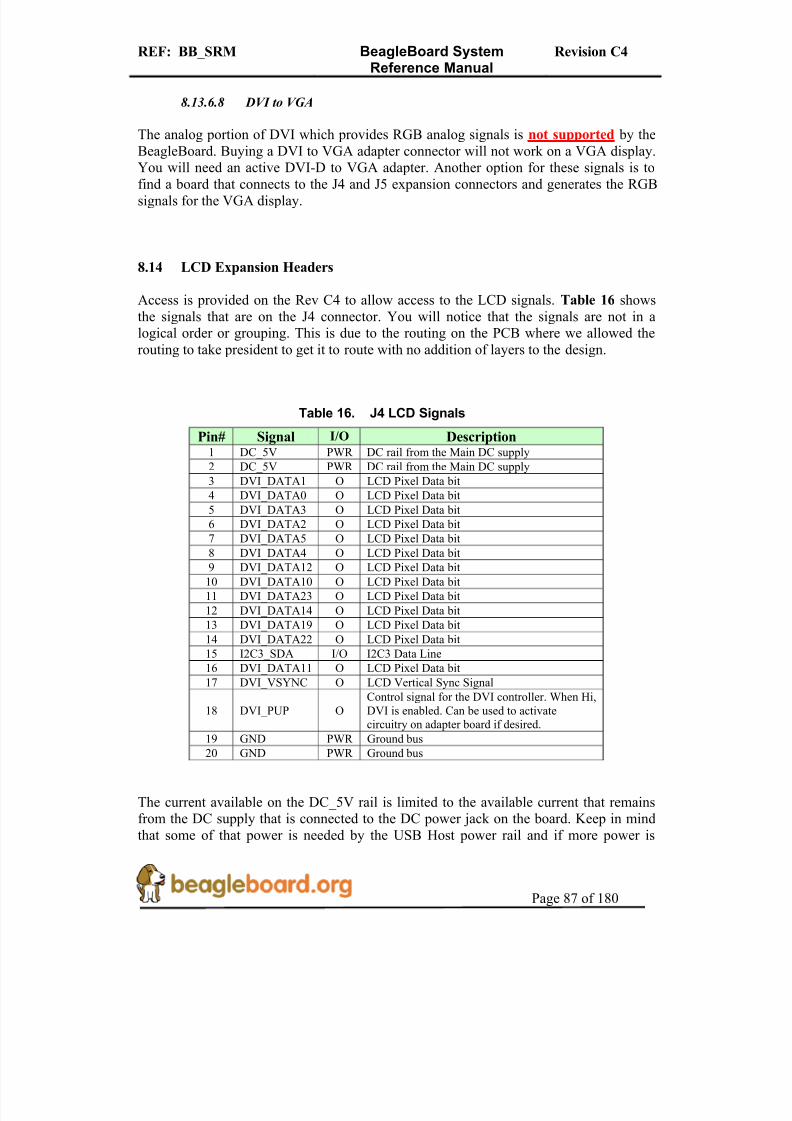
8/2/2019 Beagle Board Manual Rev. C4
http://slidepdf.com/reader/full/beagle-board-manual-rev-c4 87/180
REF: BB_SRM BeagleBoard SystemReference Manual
Revision C4
Page 87 of 180
8.13.6.8 DVI to VGA
The analog portion of DVI which provides RGB analog signals is not supported by theBeagleBoard. Buying a DVI to VGA adapter connector will not work on a VGA display.You will need an active DVI-D to VGA adapter. Another option for these signals is to
find a board that connects to the J4 and J5 expansion connectors and generates the RGBsignals for the VGA display.
8.14 LCD Expansion Headers
Access is provided on the Rev C4 to allow access to the LCD signals. Table 16 showsthe signals that are on the J4 connector. You will notice that the signals are not in alogical order or grouping. This is due to the routing on the PCB where we allowed therouting to take president to get it to route with no addition of layers to the design.
Table 16. J4 LCD Signals
Pin# Signal I/O Description1 DC_5V PWR DC rail from the Main DC supply
2 DC_5V PWR DC rail from the Main DC supply
3 DVI_DATA1 O LCD Pixel Data bit
4 DVI_DATA0 O LCD Pixel Data bit
5 DVI_DATA3 O LCD Pixel Data bit
6 DVI_DATA2 O LCD Pixel Data bit
7 DVI_DATA5 O LCD Pixel Data bit
8 DVI_DATA4 O LCD Pixel Data bit9 DVI_DATA12 O LCD Pixel Data bit
10 DVI_DATA10 O LCD Pixel Data bit
11 DVI_DATA23 O LCD Pixel Data bit
12 DVI_DATA14 O LCD Pixel Data bit
13 DVI_DATA19 O LCD Pixel Data bit
14 DVI_DATA22 O LCD Pixel Data bit
15 I2C3_SDA I/O I2C3 Data Line
16 DVI_DATA11 O LCD Pixel Data bit
17 DVI_VSYNC O LCD Vertical Sync Signal
18 DVI_PUP OControl signal for the DVI controller. When Hi,DVI is enabled. Can be used to activatecircuitry on adapter board if desired.
19 GND PWR Ground bus
20 GND PWR Ground bus
The current available on the DC_5V rail is limited to the available current that remainsfrom the DC supply that is connected to the DC power jack on the board. Keep in mindthat some of that power is needed by the USB Host power rail and if more power is

8/2/2019 Beagle Board Manual Rev. C4
http://slidepdf.com/reader/full/beagle-board-manual-rev-c4 88/180

8/2/2019 Beagle Board Manual Rev. C4
http://slidepdf.com/reader/full/beagle-board-manual-rev-c4 89/180
REF: BB_SRM BeagleBoard SystemReference Manual
Revision C4
Page 89 of 180
8.15 S-Video
A single S-Video port is provided on the BeagleBoard. Figure 41 is the design of the S-Video interface.
TV_OUT1
C140
47pF
C141
47pF
TV_VFB1
TV_VFB2 TV_OUT2
TV_VFB2R66 1.65K
L7
3.3uH
P11
SVideoConn
P11
P22
P33
P44
MH1MH1
MH2MH2
MH3MH3
TV_OUT1
L8
3.3uH
U12BOMAP35xx_ES3.0
TV_OUT2W28
TV_OUT1Y28
TV_VFB1Y27
TV_VREFW26 TV_VFB2W27R67 1.65K
TV_VREF
C142
0.1uF
TV_VFB1
TV/S-Video Conn
TV_OUT2
Figure 41. S-Video Interface
Table 18 is the list of the signals on the S-Video interface and their definitions.
Table 18. S-Video Interface Signals
Signal I/O Description
tv_out1 O TV analog output composite
tv_out2 O TV analog output S-VIDEO
tv_vref I Reference output voltage from internal bandgaptv_vfb1 O Amplifier feedback node
tv_vfb2 O Amplifier feedback node
Power to the internal DAC is supplied by the TPS65950 via the VDAC_1V8 rail. Figure
37 reflects the filtering that is used on these rails, including the input VBAT rail.A 47pf CAP and 3.3uh inductor are across the feedback resistors to improve the qualityof the S-Video signal.

8/2/2019 Beagle Board Manual Rev. C4
http://slidepdf.com/reader/full/beagle-board-manual-rev-c4 90/180
REF: BB_SRM BeagleBoard SystemReference Manual
Revision C4
Page 90 of 180
8.16 RS232 Port
A single RS232 port is provided on the BeagleBoard and provides access to the TX andRX lines of UART3 on the OMAP3530. Figure 42 shows the design of the RS232 port.
232_C1-
232_C1+
VIO_1V83.3V
C111
0.1uF10V
C1100.1uF10V
R 54 10K
RS232_TX1
232_V-
232_V+
RS232_RX1
U10
SN65C3221EPW
EN1
C1+2
C1-4
C2+5
C2-6
RIN8
G N D
1 4
V C C
1 5
FORCEOFF16
V+3
V-7
ROUT9
DOUT13
INVALID10
FORCEON12
DIN11
C115
0.1uF10V
C118
0.1uF10V
C116
0.1uF10V
C114
0.1uF10V
C117
0.1uF10V
3.3V
TP22
TESTPT1
TP21
TESTPT1
P9
HEADER 5X2
2
468
10
1
3579
232_C2+
232_C2-
UART3_TX_3VUART3_RX_3V
232OE
UART3 Serial Port
UART3_RX3UART3_TX3
U9
TXS0102 (D CU)
A15
B18VCCA
3VCCB
7
OE6
GND2 A2
4B2
1
Figure 42. RS232 Interface Design
8.16.1 OMAP3530 Interface
Two lines, UART3_Tx and UART3_Rx, are provided by the OMAP3530. The UART3 function contains a programmable baud generator and a set of fixed dividers that dividethe 48-MHz clock input down to the expected baud rate and also supports auto bauding.
8.16.2 OMAP3530 Level Translator
All of the I/O levels from the OMAP3530 are 1.8V while the transceiver used runs at3.3V. This requires that the voltage levels be translated. This is accomplished by theTXS0102 which is a two-bit noninverting translator that uses two separate configurable power-supply rails. The A port tracks VCCA, 1.8V and the B port tracks VCCB, 3.3V.This allows for low-voltage bidirectional translation between the two voltage nodes.When the output-enable (OE) input is low, all outputs are placed in the high-impedancestate. In this design, the OE is tied high via a 10K ohm resistor to insure that it is alwayson.
8.16.3 RS232 Transceiver
The RS232 transceiver used is the SN65C322 which consists of one line driver, one linereceiver, and a dual charge-pump circuit with ±15-kV IEC ESD protection pin to pin(serial-port connection pins, including GND). These devices provide the electricalinterface between an asynchronous communication controller and the serial-portconnector. The charge pump and four small external capacitors allow operation from a

8/2/2019 Beagle Board Manual Rev. C4
http://slidepdf.com/reader/full/beagle-board-manual-rev-c4 91/180
REF: BB_SRM BeagleBoard SystemReference Manual
Revision C4
Page 91 of 180
single 3-V to 5.5-V supply. The SN65C3221 operates at data signaling rates up to 1Mbit/s and a driver output slew rate of 24 V/ms to 150 V/ms. While the OMAP3530 caneasily drive a 1Mbit/S rate, your results may vary based on cabling, distance, and theloads and drive capability on the other end of the RS232 port.
The transceiver is powered from the 3.3V rail and is active at power up. This allows the port to be used for UART based peripheral booting over the port.
8.16.4 Connector
Access to the RS232 port is through a 10pin header, P9. Connection to the header isthrough a 10 pin IDC to 9 pin D-sub cable. This header requires the use of an ATI-
Everex type cable. This is the only cable that will work. This cable is readily availablefrom a number of sources and is commonly found on many PC motherboards and is notsupplied with the BeagleBoard. Figure 43 is a picture of what the cable assembly looks
like.
Figure 43. RS232 Cable
When purchasing, make sure the ATI-Everex or pass through cable is ordered.
8.17 Indicators
There are four green indicators on the BeagleBoard:
o Power o PMU_STATo USER0o USER1
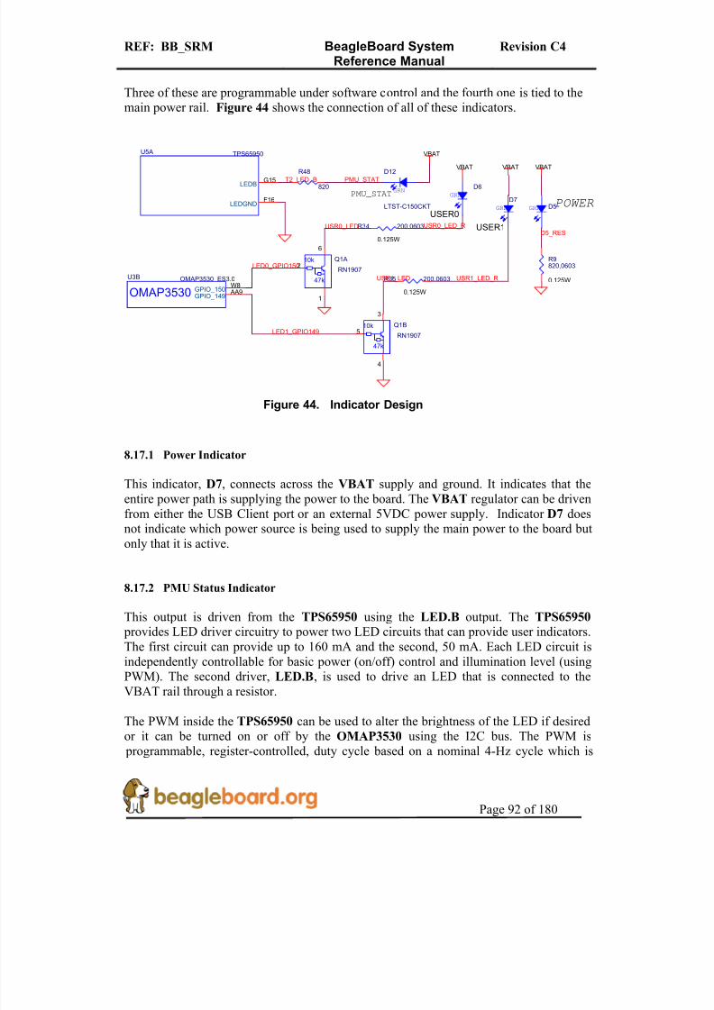
8/2/2019 Beagle Board Manual Rev. C4
http://slidepdf.com/reader/full/beagle-board-manual-rev-c4 92/180
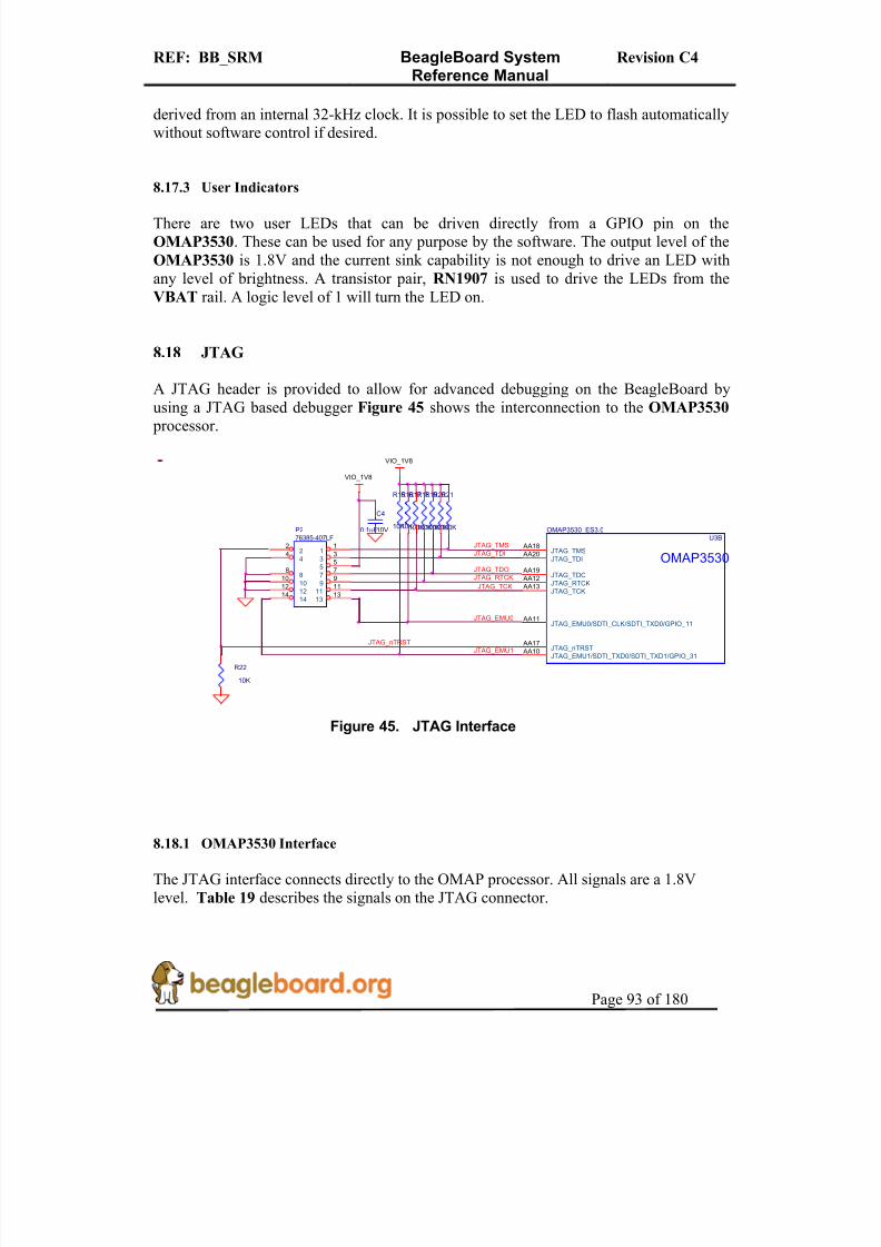
8/2/2019 Beagle Board Manual Rev. C4
http://slidepdf.com/reader/full/beagle-board-manual-rev-c4 93/180

8/2/2019 Beagle Board Manual Rev. C4
http://slidepdf.com/reader/full/beagle-board-manual-rev-c4 94/180
REF: BB_SRM BeagleBoard SystemReference Manual
Revision C4
Page 94 of 180
Table 19. JTAG Signals
Signal Description I/OJTAG_TMS Test mode select I/O
JTAG_TDI Test data input I
JTAG_TDO Test Data Output O
JTAG_RTCK ARM Clock Emulation OJTAG_TCK Test Clock I
JTAG_nTRST Test reset I
JTAG_EMU0 Test emulation 0 I/O
JTAG_EMU1 Test emulation 1 I/O
8.18.2 Connector
The JTAG interface uses a 14 pin connector. All JTAG emulator modules should be ableto support this interface. Contact your emulator supplier for further information or if anadapter is needed.
8.19 Expansion Header
The expansion header is provided to allow a limited number of functions to be added tothe BeagleBoard via the addition of a daughtercard.
Figure 46 is the design of the expansion connector and the interfaces to the OMAP3530.
Figure 46. Expansion Header
NOTE: The Expansion header itself is NOT provided on the BeagleBoard. This is user installed option. This header is not populated on the BeagleBoard so that based on theusage scenario the user chooses; it can be populated as needed (Top, Bottom, Top rightangle, or Bottom Right angle). The user should take care in installing this header.
MCBSP3_FSXMMC2_DAT6MMC2_DAT5
I2C2_SDA
MCBSP3_CLKX
OMAP3
U3B OMAP3_ES3.0
AA25 AE5 AE6
AB26
Y21 AA21
V21
U21 K26 W21
AF15 AE15
McBSP3_CLKX McBSP3_FSX McBSP3_DR
McBSP3_DX
McBSP1_CLKR McBSP1_FSR
McBSP1_DX
McBSP1_DR McBSP1_FSX
McBSP1_CLKX
I2C2_SCL I2C2_SDA
MMC2_DAT1
J3
HEADER 14X2
2
468
10121416182022242628
1
3579111315171921232527
MMC2_DAT0
MCBSP1_FSR
To the power circuitryTo the Reset circuitry
OMAP3
U3A OMAP3_ES3.0
AE2 AG5 AH5 AH4 AG4 AF4 AE4 AH3 AF3 AE3
MMC2_CLKMMC2_CMDMMC2_DAT0MMC2_DAT1MMC2_DAT2MMC2_DAT3MMC2_DAT4MMC2_DAT5MMC2_DAT6MMC2_DAT7
MCBSP1_CLKR
MCBSP1_DX
VIO_1V8DC_5V
MMC2_DAT2
UART2_CTS
MCBSP3_DR
MCBSP1_DR
MCBSP1_CLKX
MMC2_DAT7
nRESET
MMC2_DAT4
MMC2_CMD
MMC2_DAT3
nUSB_DC_EN
MMC2_CLKOI2C2_SCL
MCBSP1_FSX

8/2/2019 Beagle Board Manual Rev. C4
http://slidepdf.com/reader/full/beagle-board-manual-rev-c4 95/180
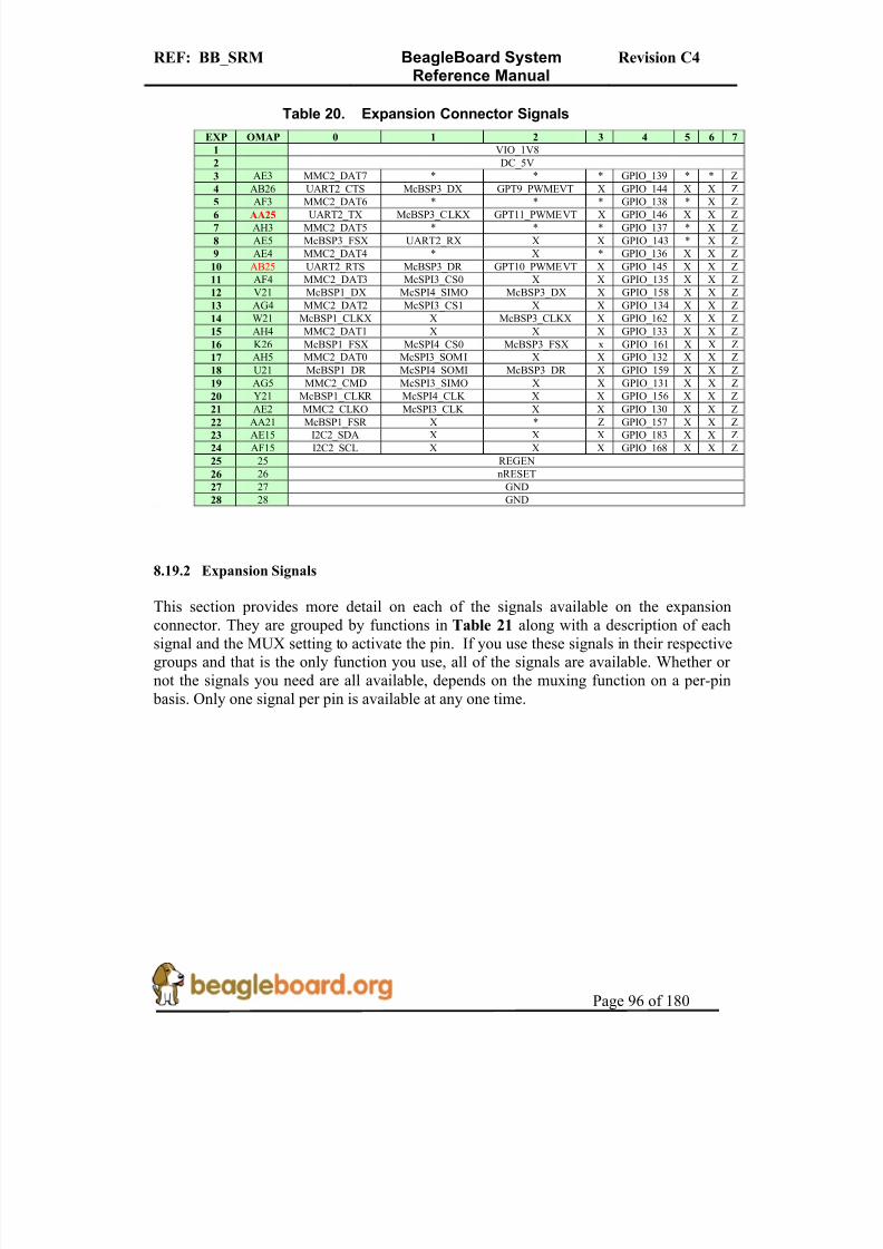
8/2/2019 Beagle Board Manual Rev. C4
http://slidepdf.com/reader/full/beagle-board-manual-rev-c4 96/180

8/2/2019 Beagle Board Manual Rev. C4
http://slidepdf.com/reader/full/beagle-board-manual-rev-c4 97/180
REF: BB_SRM BeagleBoard SystemReference Manual
Revision C4
Page 97 of 180
Table 21. Expansion Connector Signal Groups
Signal Description I/O EXP OMAP MuxSD/MMC Port 2
MMC2_DAT7 SD/MMC data pin 7. I/O 3 AE3 1MMC2_DAT6 SD/MMC data pin 6. I/O 5 AF3 1MMC2_DAT5 SD/MMC data pin 5. I/O 7 AH3 1
MMC2_DAT4 SD/MMC data pin 4. I/O 9 AE4 1MMC2_DAT3 SD/MMC data pin 3. I/O 11 AF4 1MMC2_DAT2 SD/MMC data pin 2. I/O 13 AG4 1MMC2_DAT1 SD/MMC data pin 1. I/O 15 AH4 1MMC2_DAT0 SD/MMC data pin 0. I/O 17 AH5 1MMC2_CMD SD/MMC command signal. I/O 19 AG5 1MMC_CLKO SD/MMC clock signal. O 21 AE2 1
McBSP Port 1McBSP1_DR Multi channel buffered serial port receive I 18
McBSP1_CLKS ------------------------------------------------------------------------- - N/A N/AMcBSP1_FSR Multi channel buffered serial port transmit frame sync RCV I/O 22McBSP1_DX Multi channel buffered serial port transmit I/O 12
McBSP1_CLKX Multi channel buffered serial port transmit clock I/O 14McBSP1_FSX Multi channel buffered serial port transmit frame sync XMT I/O 16
McBSP1_CLKR Multi channel buffered serial port receive clock I/O 20I2C Port 2
I2C2_SDA I2C data line. IOD 23I2C2_SCL I2C clock line IOD 24
McBSP Port 3McBSP3_DR Multi channel buffered serial port receive I 10,18McBSP3_DX Multi channel buffered serial port transmit I/O 4,12
McBSP3_CLKX Multi channel buffered serial port receive clock I/O 6,14McBSP3_FSX Multi channel buffered serial port frame sync transmit I/O 8,16
General Purpose I/O PinsGPIO_130 GP Input/Output pin. Can be used as an interrupt pin. I/O 21GPIO_131 GP Input/Output pin. Can be used as an interrupt pin. I/O 19GPIO_132 GP Input/Output pin. Can be used as an interrupt pin. I/O 17GPIO_133 GP Input/Output pin. Can be used as an interrupt pin. I/O 15GPIO_134 GP Input/Output pin. Can be used as an interrupt pin. I/O 13GPIO_135 GP Input/Output pin. Can be used as an interrupt pin. I/O 11GPIO_136 GP Input/Output pin. Can be used as an interrupt pin. I/O 9GPIO_137 GP Input/Output pin. Can be used as an interrupt pin. I/O 7GPIO_138 GP Input/Output pin. Can be used as an interrupt pin. I/O 5GPIO_139 GP Input/Output pin. Can be used as an interrupt pin. I/O 3GPIO_143 GP Input/Output pin. Can be used as an interrupt pin. I/O 8GPIO_144 GP Input/Output pin. Can be used as an interrupt pin. I/O 4GPIO_145 GP Input/Output pin. Can be used as an interrupt pin. I/O 10GPIO_146 GP Input/Output pin. Can be used as an interrupt pin. I/O 6GPIO_156 GP Input/Output pin. Can be used as an interrupt pin. I/O 20GPIO_158 GP Input/Output pin. Can be used as an interrupt pin. I/O 12GPIO_159 GP Input/Output pin. Can be used as an interrupt pin. I/O 18GPIO_161 GP Input/Output pin. Can be used as an interrupt pin. I/O 16GPIO_162 GP Input/Output pin. Can be used as an interrupt pin. I/O 14GPIO_168 GP Input/Output pin. Can be used as an interrupt pin. I/O 24GPIO_183 GP Input/Output pin. Can be used as an interrupt pin. I/O 23
McSPI Port 3McSPI3_CS0 Multi channel SPI chip select 0 O 11
McSPI3_CS1 Multi channel SPI chip select 1 O 13McSPI3_SIMO Multi channel SPI slave in master out I/O 19McSPI3_SOMI Multi channel SPI slave out master in I/O 17McSPI3_CLK Multi channel SPI clock I/O 21
McSPI Port 4McSPI4_SIMO Multi channel SPI slave in master out I/O 12McSPI4_SOMI Multi channel SPI slave out master in I/) 18McSPI4_CS0 Multi channel SPI chip select 0 O 16McSPI4_CLK Multi channel SPI clock I/O 20
UART Port 2UART2_CTS UART clear to send. I/O 4UART2_RTS UART request to send O 10

8/2/2019 Beagle Board Manual Rev. C4
http://slidepdf.com/reader/full/beagle-board-manual-rev-c4 98/180
REF: BB_SRM BeagleBoard SystemReference Manual
Revision C4
Page 98 of 180
UART2_RX UART receive I 8UART2_TX UART transmit O 6
GPT PWMGPT9_PWMEVT PWM or event for GP timer 9 O 4GPT11_PWMEVT PWM or event for GP timer 11 O 10GPT10_PWMEVT PWM or event for GP timer 10 O 8
8.19.3 Power
The expansion connector provides two power rails. The first is the VIO_1.8V rail whichis supplied by the TPS65950. This rail is limited in the current it can supply from theTPS65950 and what remains from the current consumed by the BeagleBoard and isintended to be used to provide a rail for voltage level conversion only. It is not intendedto power a lot of circuitry on the expansion board. All signals from the BeagleBoard areat 1.8V.
The other rail is the DC_5V. The same restriction exits on this rail as mentioned in the
USB section. The amount of available power to an expansion board depends on theavailable power from the DC supply or the USB supply from the PC.
8.19.4 Reset
The nRESET signal is the main board reset signal. When the board powers up, thissignal will act as an input to reset circuitry on the expansion board. After power up, asystem reset can be generated by the expansion board by taking this signal low. Thissignal is a 1.8V level signal.
8.19.5 Power Control
There is an additional open-drain signal on the connector called REGEN. The purpose of this signal is to provide a means to control power circuitry on the expansion card to turnon and off the voltages. This insures that the power on the expansion board is turned on atthe appropriate time. Depending on what circuitry is provided on the expansion board, anadditional delay may be needed to be added before the circuitry is activated. Refer to theOMAP3530 and TPS65950 documentation for more information.
8.20 Additional Expansion Header
If you choose not to use the LCD headers for access to the LCD signals or for the DVI-Dinterface, they can also be used for other functions on the board based on the pin muxsetting of each pin. Table 22 shows the options for J4 and Table 23 shows the optionsfor J5. The MUX: column indicates which MUX mode must be set for each pin to makethe respective signals accessible on the pins of the OMAP3530.

8/2/2019 Beagle Board Manual Rev. C4
http://slidepdf.com/reader/full/beagle-board-manual-rev-c4 99/180
REF: BB_SRM BeagleBoard SystemReference Manual
Revision C4
Page 99 of 180
Table 22. J4 GPIO Signals
Pin# Signal MUX:0 MUX:2 MUX:4
3 DVI_DATA1 DATA1 UART1_RTS GPIO71
4 DVI_DATA0 DATA0 UART1_CTS GPIO70
5 DVI_DATA3 DATA3 - GPIO73
6 DVI_DATA2 DATA2 - GPIO727 DVI_DATA5 DATA5 UART3_TX GPIO75
8 DVI_DATA4 DATA4 UART3_RX GPIO74
9 DVI_DATA12 DATA12 GPIO82
10 DVI_DATA10 DATA10 - GPIO79
11 DVI_DATA23 DATA23 - GPIO93
12 DVI_DATA14 DATA14 - GPIO84
13 DVI_DATA19 DATA19 McSPI3_SIMO GPIO89
14 DVI_DATA22 DATA22 McSPI3_CS1 GPIO92
15 I2C3_SDA I2C3_SDA - -
16 DVI_DATA11 DATA11 - GPIO81
17 DVI_VSYNC VSYNC - GPIO68
18 DVI_PUP DVI_PUP - -
Table 23. J5 GPIO Signals
Pin# Signal MUX:0 MUX:2 MUX:4
3 DVI_DATA20 DATA20 McSPI3_SOMI GPIO90
4 DVI_DATA21 DATA21 McSPI3_CS0 GPIO91
5 DVI_DATA17 DATA17 - GPIO87
6 DVI_DATA18 DATA18 McSPI3_CLK GPIO88
7 DVI_DATA15 DATA15 - GPIO85
8 DVI_DATA16 DATA16 - GPIO86
9 DVI_DATA7 DATA7 UART1_RX GPIO77
10 DVI_DATA13 DATA13 - GPIO83
11 DVI_DATA8 DATA8 - GPIO78
12 NC - - -
13 DVI_DATA9 DATA9 - GPIO79
14 I2C3_SCL I2C3_SCL -
15 DVI_DATA6 DATA6 UART1_TX GPIO_76
16 DVI_CLK+ PCLK - GPIO66
17 DVI_DEN DEN - GPIO69
18 DVI_HSYNC HSYNC - GPIO67

8/2/2019 Beagle Board Manual Rev. C4
http://slidepdf.com/reader/full/beagle-board-manual-rev-c4 100/180
REF: BB_SRM BeagleBoard SystemReference Manual
Revision C4
Page 100 of 180
9.0 Connector Pinouts and Cables
This section provides a definition of the pinouts and cables to be used with all of theconnectors and headers on the BeagleBoard.
THERE ARE NO CABLES SUPPLIED WITH THE BEAGLEBOARD.
9.1 Power Connector
Figure 47 is a picture of the BeagleBoard power connector with the pins identified. Thesupply must have a 2.1mm center hot connector with a 5.5mm outside diameter.
Figure 47. Power Connector
The supply must be at least 500mA with a maximum of 2A. If the expansion connector isused, more power will be required depending on the load of the devices connected to theexpansion connector.
WARNING: DO NOT PLUG IN ANYTHING BUT
5V TO THE DC CONNECTOR OR THE BOARD
WILL BE DAMAGED!!!!

8/2/2019 Beagle Board Manual Rev. C4
http://slidepdf.com/reader/full/beagle-board-manual-rev-c4 101/180
REF: BB_SRM BeagleBoard SystemReference Manual
Revision C4
Page 101 of 180
9.2 USB OTG
Figure 48 is a picture of the BeagleBoard USB OTG connector with the pins identified.
Figure 48. USB OTG Connector
The shorting pads to convert the OTG port to a Host mode are found in Figure 49.
Figure 49. OTG Host Shorting Pads

8/2/2019 Beagle Board Manual Rev. C4
http://slidepdf.com/reader/full/beagle-board-manual-rev-c4 102/180
REF: BB_SRM BeagleBoard SystemReference Manual
Revision C4
Page 102 of 180
9.3 S-Video
Figure 50 is the S-Video connector on the BeagleBoard.
Figure 50. S-Video Connector

8/2/2019 Beagle Board Manual Rev. C4
http://slidepdf.com/reader/full/beagle-board-manual-rev-c4 103/180
REF: BB_SRM BeagleBoard SystemReference Manual
Revision C4
Page 103 of 180
9.4 DVI-D
Figure 51 is the pinout of the DVI-D connector on BeagleBoard.
Figure 51. DVI-D Connector
Table 24 is the pin numbering of the two ends of the cable as it relates to the signals used in theDVI-D interface itself.
Table 24. DVI-D to HDMI CableSIGNAL DVI-D PIN# HDMI PIN#
DATA 2- 1 3
DATA 2+ 2 1
SHIELD 3 2
4
5
DDS CLOCK 6 15
DDS DATA 7 16
8
DATA 1- 9 6
DATA 1+ 10 4
SHIELD 11 5
12
13
5V 14 18
GROUND (5V) 15 17
16
DATA 0- 17 9
SIGNAL DVI-D PIN# DVI-D PIN#
DATA 0+ 18 7

8/2/2019 Beagle Board Manual Rev. C4
http://slidepdf.com/reader/full/beagle-board-manual-rev-c4 104/180
REF: BB_SRM BeagleBoard SystemReference Manual
Revision C4
Page 104 of 180
SHIELD 19 5
20
21
22
CLOCK+ 23 10
CLOCK- 24 12
DO NOT PLUG IN THE DVI-D CONNECTOR TO A DISPLAY WITH THE
BEAGLEBAORD POWERED ON. PLUG IN THE CABLE TO THE DISPLAY
AND THEN POWER ON THE BEAGLEBOARD.
Figure 52 is the cable to be used to connect to an LCD monitor.
Figure 52. DVI-D Cable

8/2/2019 Beagle Board Manual Rev. C4
http://slidepdf.com/reader/full/beagle-board-manual-rev-c4 105/180
REF: BB_SRM BeagleBoard SystemReference Manual
Revision C4
Page 105 of 180
9.5 LCD
This section covers the pair of headers that provide access to the raw 1.8V DSS signalsfrom the OMAP3530 processor. This provides the ability to create adapters for suchthings as different LCD panels, LVDS interfaces, etc.
9.5.1 Connector Pinout
The Table 25 and 26 define the pinout of the LCD connectors. All signal levels are 1.8Vwith the exception of DVI_PUP signal which is 3.3V.
Table 25. J4 LCD Signals
Pin# Signal I/O Description1 DC_5V PWR DC rail from the Main DC supply
2 DC_5V PWR DC rail from the Main DC supply
3 DVI_DATA1 O LCD Pixel Data bit
4 DVI_DATA0 O LCD Pixel Data bit
5 DVI_DATA3 O LCD Pixel Data bit
6 DVI_DATA2 O LCD Pixel Data bit
7 DVI_DATA5 O LCD Pixel Data bit
8 DVI_DATA4 O LCD Pixel Data bit
9 DVI_DATA12 O LCD Pixel Data bit
10 DVI_DATA10 O LCD Pixel Data bit
11 DVI_DATA23 O LCD Pixel Data bit
12 DVI_DATA14 O LCD Pixel Data bit13 DVI_DATA19 O LCD Pixel Data bit
14 DVI_DATA22 O LCD Pixel Data bit
15 I2C3_SDA I/O I2C3 Data Line
16 DVI_DATA11 O LCD Pixel Data bit
17 DVI_VSYNC O LCD Vertical Sync Signal
18 DVI_PUP O
Control signal for the DVIcontroller. When Hi, DVI isenabled. Can be used to activatecircuitry on adapter board if desired.
19 GND PWR Ground bus
20 GND PWR Ground bus
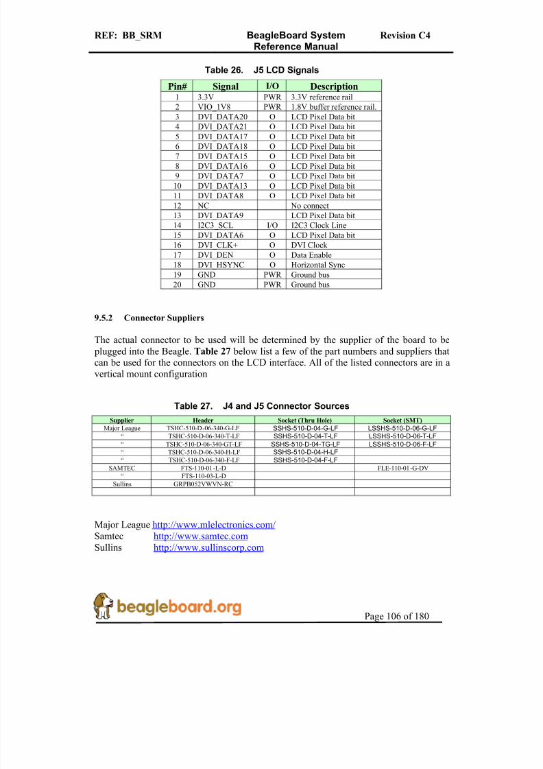
8/2/2019 Beagle Board Manual Rev. C4
http://slidepdf.com/reader/full/beagle-board-manual-rev-c4 106/180
REF: BB_SRM BeagleBoard SystemReference Manual
Revision C4
Page 106 of 180
Table 26. J5 LCD Signals
Pin# Signal I/O Description1 3.3V PWR 3.3V reference rail
2 VIO_1V8 PWR 1.8V buffer reference rail.
3 DVI_DATA20 O LCD Pixel Data bit
4 DVI_DATA21 O LCD Pixel Data bit5 DVI_DATA17 O LCD Pixel Data bit
6 DVI_DATA18 O LCD Pixel Data bit
7 DVI_DATA15 O LCD Pixel Data bit
8 DVI_DATA16 O LCD Pixel Data bit
9 DVI_DATA7 O LCD Pixel Data bit
10 DVI_DATA13 O LCD Pixel Data bit
11 DVI_DATA8 O LCD Pixel Data bit
12 NC No connect
13 DVI_DATA9 LCD Pixel Data bit
14 I2C3_SCL I/O I2C3 Clock Line
15 DVI_DATA6 O LCD Pixel Data bit
16 DVI_CLK+ O DVI Clock
17 DVI_DEN O Data Enable
18 DVI_HSYNC O Horizontal Sync
19 GND PWR Ground bus
20 GND PWR Ground bus
9.5.2 Connector Suppliers
The actual connector to be used will be determined by the supplier of the board to be plugged into the Beagle. Table 27 below list a few of the part numbers and suppliers thatcan be used for the connectors on the LCD interface. All of the listed connectors are in a
vertical mount configuration
Table 27. J4 and J5 Connector Sources
Supplier Header Socket (Thru Hole) Socket (SMT)
Major League TSHC-510-D-06-340-G-LF SSHS-510-D-04-G-LF LSSHS-510-D-06-G-LF“ TSHC-510-D-06-340-T-LF SSHS-510-D-04-T-LF LSSHS-510-D-06-T-LF“ TSHC-510-D-06-340-GT-LF SSHS-510-D-04-TG-LF LSSHS-510-D-06-F-LF“ TSHC-510-D-06-340-H-LF SSHS-510-D-04-H-LF“ TSHC-510-D-06-340-F-LF SSHS-510-D-04-F-LF
SAMTEC FTS-110-01-L-D FLE-110-01-G-DV
“ FTS-110-03-L-D
Sullins GRPB052VWVN-RC
Major League http://www.mlelectronics.com/ Samtec http://www.samtec.com Sullins http://www.sullinscorp.com
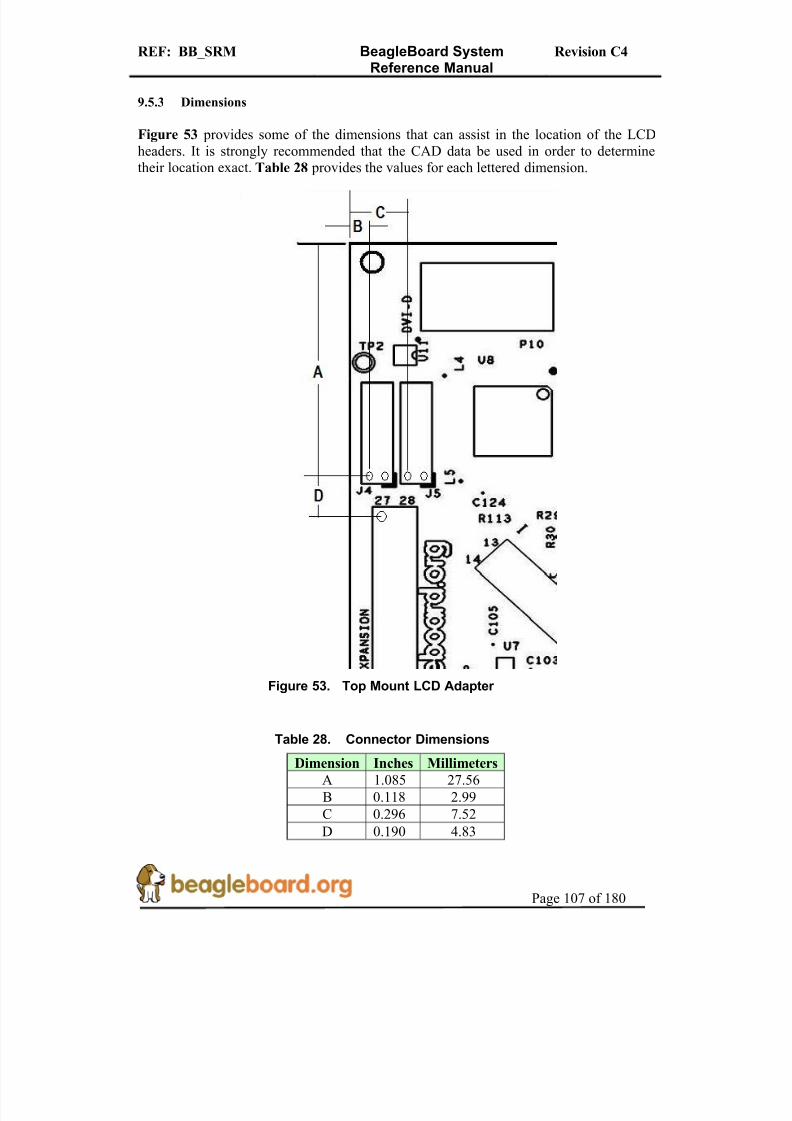
8/2/2019 Beagle Board Manual Rev. C4
http://slidepdf.com/reader/full/beagle-board-manual-rev-c4 107/180
REF: BB_SRM BeagleBoard SystemReference Manual
Revision C4
Page 107 of 180
9.5.3 Dimensions
Figure 53 provides some of the dimensions that can assist in the location of the LCDheaders. It is strongly recommended that the CAD data be used in order to determinetheir location exact. Table 28 provides the values for each lettered dimension.
Figure 53. Top Mount LCD Adapter
Table 28. Connector Dimensions
Dimension Inches Millimeters
A 1.085 27.56
B 0.118 2.99
C 0.296 7.52
D 0.190 4.83

8/2/2019 Beagle Board Manual Rev. C4
http://slidepdf.com/reader/full/beagle-board-manual-rev-c4 108/180

8/2/2019 Beagle Board Manual Rev. C4
http://slidepdf.com/reader/full/beagle-board-manual-rev-c4 109/180
REF: BB_SRM BeagleBoard SystemReference Manual
Revision C4
Page 109 of 180
9.5.4.2 Bottom Mounting
Figure 55 shows the board being mounted under the BeagleBoard.
Figure 55. Bottom Mount LCD Adapter
Adapter
LCD Connector
Buffer Logic BeagleBoard

8/2/2019 Beagle Board Manual Rev. C4
http://slidepdf.com/reader/full/beagle-board-manual-rev-c4 110/180
REF: BB_SRM BeagleBoard SystemReference Manual
Revision C4
Page 110 of 180
9.6 Audio Connections
Figure 56 is the audio input jack required to connect to the BeagleBoard.
Figure 56. Audio In Plug
Figure 57 is the actual connector used on the BeagleBoard.
Figure 57. Audio In Plug
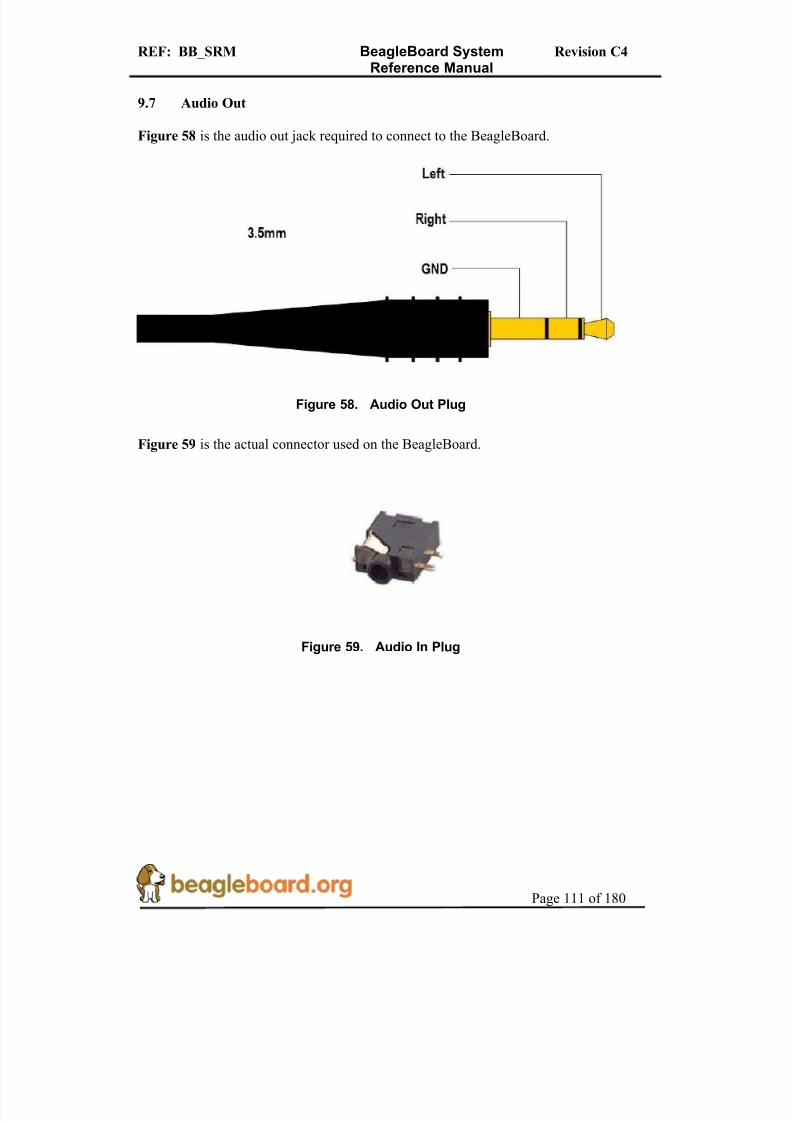
8/2/2019 Beagle Board Manual Rev. C4
http://slidepdf.com/reader/full/beagle-board-manual-rev-c4 111/180
REF: BB_SRM BeagleBoard SystemReference Manual
Revision C4
Page 111 of 180
9.7 Audio Out
Figure 58 is the audio out jack required to connect to the BeagleBoard.
Figure 58. Audio Out Plug
Figure 59 is the actual connector used on the BeagleBoard.
Figure 59. Audio In Plug

8/2/2019 Beagle Board Manual Rev. C4
http://slidepdf.com/reader/full/beagle-board-manual-rev-c4 112/180

8/2/2019 Beagle Board Manual Rev. C4
http://slidepdf.com/reader/full/beagle-board-manual-rev-c4 113/180
REF: BB_SRM BeagleBoard SystemReference Manual
Revision C4
Page 113 of 180
If a 20 pin connector is provided on the JTAG emulator, then a 20 pin to 14 pin adapter must be used. You may also use emulators that are either equipped with a 14 pinconnector or are universal in nature.
Figure 61 shows an example of a 14 pin to 20 pin adapter.
Figure 61. JTAG 14 to 20 Pin Adapter
Figure 62 shows how the JTAG cable is to be routed when connected to theBeagleBoard.
Figure 62. JTAG Connector Pinout
C4

8/2/2019 Beagle Board Manual Rev. C4
http://slidepdf.com/reader/full/beagle-board-manual-rev-c4 114/180
REF: BB_SRM BeagleBoard SystemReference Manual
Revision C4
Page 114 of 180
9.9 RS232
Figure 63 is the RS232 header on the BeagleBoard with the pin numbers identified.
Figure 63. RS232 Header
Figure 64 is the cable that is required in order to access the RS232 header. This cable can be purchased from various sources and is referred to as the ATI/Everex type cable.
Figure 64. RS232 Flat Cable

8/2/2019 Beagle Board Manual Rev. C4
http://slidepdf.com/reader/full/beagle-board-manual-rev-c4 115/180
REF: BB_SRM BeagleBoard SystemReference Manual
Revision C4
Page 115 of 180
9.10 Expansion
We are changing the configuration of the expansion header on all Beagle boards. Thiswill standardize on the configuration for compatibility with expansion cards. The socketwill be mounted on the BACKSIDE of the board.
Figure 65 is a drawing and picture of the socket that is specified.
Figure 65. Expansion Sockets
The selected supplier for this socket is Major League Electronicshttp://www.mlelectronics.com/ and the part number is LSWSS-114-D-02-T-LF. Other suppliers may be available as well and can be used as long as it is compatible with thissocket. This socket is mounted on the BACK of the BeagleBoard.

8/2/2019 Beagle Board Manual Rev. C4
http://slidepdf.com/reader/full/beagle-board-manual-rev-c4 116/180

8/2/2019 Beagle Board Manual Rev. C4
http://slidepdf.com/reader/full/beagle-board-manual-rev-c4 117/180
REF: BB_SRM BeagleBoard SystemReference Manual
Revision C4
Page 117 of 180
Figure 67 shows the location of the battery on the Beagle Board.
Figure 67. Optional Battery Location
Following are the steps required to install the battery.
1) Remove all cables from the board.2) Remove R66 from the board as shown on Figure 67.3) Using Figure 66, locate the positive (+) lead of the battery.4) Insert the (+) lead into the hole that is marked (+) on Figure 67.
C4

8/2/2019 Beagle Board Manual Rev. C4
http://slidepdf.com/reader/full/beagle-board-manual-rev-c4 118/180
REF: BB_SRM BeagleBoard SystemReference Manual
Revision C4
Page 118 of 180
10.0 BeagleBoard Accessories
Throughout this manual various items are mentioned as not being provided with thestandard BeagleBoard package or as options to extend the features of the BeagleBoard.The concept behind BeagleBoard is that different features and functions can be added toBeagleBoard by bringing your own peripherals. This has several key advantages:
o User can choose which peripherals to add.o User can choose the brand of peripherals based on driver availability and ability
to acquire the particular peripheralo User can add these peripherals at a lower cost than if they were integrated into the
BeagleBoard.
This section covers these accessories and add-ons and provides information on wherethey may be obtained. Obviously things can change very quickly as it relates to devicesthat may be available. Please check BeagleBoard.org for an up to date listing of these peripherals.
Inclusion of any products in this section does not guarantee that they willoperate with all SW releases. It is up to the user to find the appropriatedrivers for each of these products. Information provided here is intended toexpose the capabilities of what can be done with the BeagleBoard and how itcan be expanded.
All pricing information provided is subject to change an din most cases is likely to belower depending on the products purchased and from where they are purchased.
Covered in this section are the following accessories:
o DC Power Supplieso Serial Ribbon cableo USB Hubso USB Thumb Driveso DVI-D Cableso DVI-D Monitorso SD/MMC Cardso USB to Ethernet
o USB to WiFio USB Bluetootho Expansion Cards
NO CABLES OR POWER SUPPLIES ARE PROVIDED WITH THE BEAGLEBOARD.

8/2/2019 Beagle Board Manual Rev. C4
http://slidepdf.com/reader/full/beagle-board-manual-rev-c4 119/180
REF: BB_SRM BeagleBoard SystemReference Manual
Revision C4
Page 119 of 180
10.1 DC Power Supply
Tabletop or wall plug supplies can be used to power BeagleBoard. Table 30 provides thespecifications for the BeagleBoard DC supply. Supplies that provide additional currentthan what is specified can be used if additional current is needed for add on accessories.
The amount specified is equal to that supplied by a USB port.
Table 30. DC Power Supply Specifications
Specification Requirement Unit
Voltage 5.0 V
Current 500mA (minimum) mA
Connector 2.1mm x 5.5mm Center hot
It is recommended that a supply higher than 500mA be used if higher current peripheralsare expected to be used or if expansion boards are added.
Table 31 lists some power supplies that will work with the BeagleBoard.
Table 31. DC Power Supplies
Part # Manufacturer Supplier Price
EPS050100-P6P CUI Digi-Key $7
DPS050200UPS-P5P-SZ CUI Digi-Key $16
Figure 68 is a picture of the type of power supply that will be used on the BeagleBoard.
Figure 68. DC Power Supply

8/2/2019 Beagle Board Manual Rev. C4
http://slidepdf.com/reader/full/beagle-board-manual-rev-c4 120/180
REF: BB_SRM BeagleBoard SystemReference Manual
Revision C4
Page 120 of 180
10.2 Serial Ribbon Cable
Figure 69 is an example of the serial ribbon cable for the BeagleBoard. Other serialcables that will work on the board may have a different appearance.
Figure 69. RS232 Cable
If you like, you can al71 67.
Figure 70. RS232 Cable Wiring

8/2/2019 Beagle Board Manual Rev. C4
http://slidepdf.com/reader/full/beagle-board-manual-rev-c4 121/180
REF: BB_SRM BeagleBoard SystemReference Manual
Revision C4
Page 121 of 180
Table 32 shows the pinout of the ribbon cable connector.
Table 32. Cable Pinout
Ribbon Cable DB9
1 1
2 2
3 3
4 4
5 5
6 6
7 7
8 8
9 9
10 10
10.3 USB Hubs
There are no known or anticipated issues with USB hubs. However, it should be notedthat a self powered hub is highly recommended. Table 34 is a list of Hubs that have beentested on the BeagleBoard.
Table 33. USB Hubs Tested
Supplier Part Number
IOGEAR GUH274
D-Link DUB-H4 2.0
Vakoss TC-204-NS
10.4 DVI Cables
In order to connect the DVI-D interface to a LCD monitor, a HDMI to DVI-D cable isrequired. Figure 71 is a picture of a HDMI to DVI-D cable.

8/2/2019 Beagle Board Manual Rev. C4
http://slidepdf.com/reader/full/beagle-board-manual-rev-c4 122/180

8/2/2019 Beagle Board Manual Rev. C4
http://slidepdf.com/reader/full/beagle-board-manual-rev-c4 123/180
REF: BB_SRM BeagleBoard SystemReference Manual
Revision C4
Page 123 of 180
10.7 USB to Ethernet
There are several USB to Ethernet adapters on the market and Figure 72 shows a few of these devices. These devices can easily add Ethernet connectivity to BeagleBoard by
using the USB OTG port in the host. This will require a special cable to convert theminiAB connector to a Type A or a hub can also be used. These are provided as examplesonly. Check BeagleBoard.org for information on devices that have drivers available for them.
Figure 72. USB to Ethernet Adapters
Table 37 provides examples of USB to Ethernet Adapters that might be used with the
BeagleBoard. This list has not been verified. Inclusion of these items in the table does notguarantee that they will work, but is provided as examples only. Please check BeagleBoard.org for an up to date listing of the USB to Ethernet devices as well as informationon the availability of drivers.
Table 36. USB to Ethernet Adapters
Product Manufacturer Status
ASOHOUSB Airlink Not Tested
TU-ET100C 10/100Mbps TRENDnet Not Tested
SABRENT NB-USB20 Not Tested
Zonet ZUN2210 Not Tested
StarTech USB2105S Not Tested
MOSCHIP is the silicon provider for USB to Ethernet devices. The product that has beentested uses the 7830 from MOSCHIP and has a vendor ID of 9710 and a product ID of 7830. The devices above that are based upon the MOSCHIP device are highlighted in
red.
10.8 USB to WiFi
There are several USB to WiFi adapters on the market and Figure 73 shows a few of these devices. These devices can easily add WiFi connectivity to BeagleBoard by usingthe USB OTG port in the host mode. This will require a special cable to convert the

8/2/2019 Beagle Board Manual Rev. C4
http://slidepdf.com/reader/full/beagle-board-manual-rev-c4 124/180
REF: BB_SRM BeagleBoard SystemReference Manual
Revision C4
Page 124 of 180
miniAB connector to a Type A or a hub can also be used. These are provided as examplesonly. Check BeagleBoard.org for information on devices that have drivers available for them.
Figure 73. USB to WiFi
Table 38 provides a list of USB to WiFi adapters that could be used with theBeagleBoard. Inclusion of these items in the table does not guarantee that they will work, but is provided as examples only. Please check BeagleBoard.org for an up to date listingof the USB to WiFi devices as well as information on the availability of drivers.
Table 37. USB to WiFi Adapters
Product Manufacturer Status
4410-00-00AF Zoom Not TestedHWUG1 Hawkins Not Tested
TEW-429Uf Trendnet Not Tested
It should be noted that the availability of Linux drivers for various WiFi devices islimited. Before purchasing a particular device, please verify the availability of drivers for that device.
10.9 USB to Bluetooth
There are several USB to Bluetooth adapters on the market and Figure 74 shows a few of these devices. These devices can easily add Bluetooth connectivity to BeagleBoard byusing the USB OTG port in the host mode. This will require a special cable to convert theminiAB connector to a Type A or a hub can also be used. These are provided asexamples only. Check BeagleBoard.org for information on devices that have driversavailable for them and their test status.

8/2/2019 Beagle Board Manual Rev. C4
http://slidepdf.com/reader/full/beagle-board-manual-rev-c4 125/180
REF: BB_SRM BeagleBoard SystemReference Manual
Revision C4
Page 125 of 180
Figure 74. USB to Bluetooth
Table 39 provides a list of USB to Bluetooth adapters that could be used with theBeagleBoard. Inclusion of these items in the table does not guarantee that they will work, but is provided as examples only. Please check BeagleBoard.org for an up to date listingof the USB to Bluetooth devices as well as information on the availability of drivers.
Table 38. USB to Bluetooth Adapters
Product Manufacturer
TBW-105UB Trendnet
ABT-200 Airlink
F8T012-1 Belkin
10.10 Expansion Card Design
This section covers the requirements for expansion cards that are designed to mount ontothe Beagle Board..
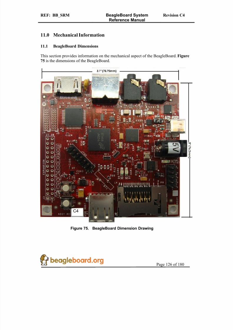
8/2/2019 Beagle Board Manual Rev. C4
http://slidepdf.com/reader/full/beagle-board-manual-rev-c4 126/180
REF: BB_SRM BeagleBoard SystemReference Manual
Revision C4
Page 126 of 180
11.0 Mechanical Information
11.1 BeagleBoard Dimensions
This section provides information on the mechanical aspect of the BeagleBoard. Figure
75 is the dimensions of the BeagleBoard.
Figure 75. BeagleBoard Dimension Drawing
C4
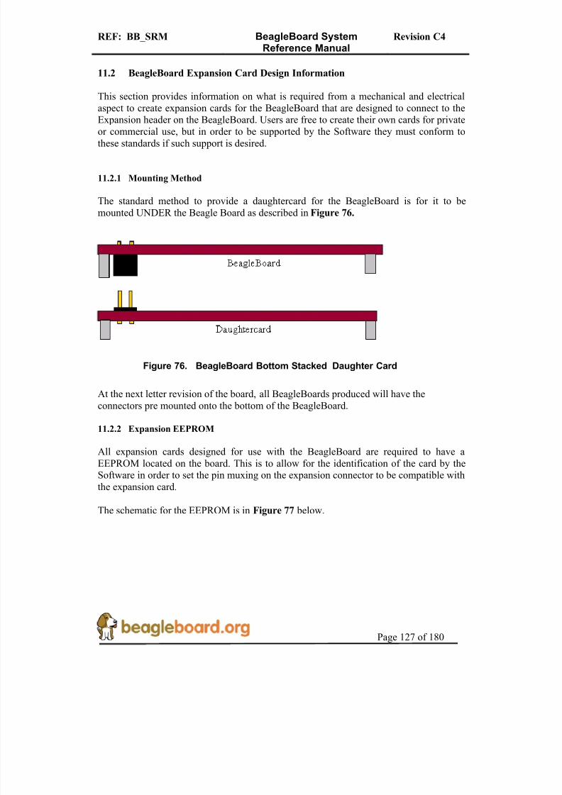
8/2/2019 Beagle Board Manual Rev. C4
http://slidepdf.com/reader/full/beagle-board-manual-rev-c4 127/180
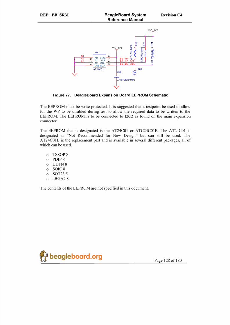
8/2/2019 Beagle Board Manual Rev. C4
http://slidepdf.com/reader/full/beagle-board-manual-rev-c4 128/180
REF: BB_SRM BeagleBoard SystemReference Manual
Revision C4
Page 128 of 180
A1 A0
A2
U8
AT24C01
A01
A12
A23
VSS4
SDA5
SCL6WP7VCC8
R 2 1
4 . 7
K , 5
% , 0 4
0 2
2
1
R 2 0
4 . 7
K , 5
% ,
0 4 0 2 2
1
C28
0.1uf,CER,0402
R 1 9
4 . 7
K , 5
% , 0
4 0 2
2
1
VIO_1V8
BB_I2C_SDABB_I2C_SCLBB_WP
TP7
TP
VIO_ 1V8
Figure 77. BeagleBoard Expansion Board EEPROM Schematic
The EEPROM must be write protected. It is suggested that a testpoint be used to allowfor the WP to be disabled during test to allow the required data to be written to theEEPROM. The EEPROM is to be connected to I2C2 as found on the main expansionconnector.
The EEPROM that is designated is the AT24C01 or ATC24C01B. The AT24C01 isdesignated as “Not Recommended for New Design” but can still be used. TheAT24C01B is the replacement part and is available in several different packages, all of which can be used.
o TSSOP 8
o PDIP 8o UDFN 8o SOIC 8o SOT23 5o dBGA2 8
The contents of the EEPROM are not specified in this document.

8/2/2019 Beagle Board Manual Rev. C4
http://slidepdf.com/reader/full/beagle-board-manual-rev-c4 129/180

8/2/2019 Beagle Board Manual Rev. C4
http://slidepdf.com/reader/full/beagle-board-manual-rev-c4 130/180
REF: BB_SRM BeagleBoard SystemReference Manual
Revision C4
Page 130 of 180
12.2 Out of the Box
Each BeagleBoard comes pre-loaded with the XLoader and UBoot in Flash. When powered up, it will do the following:
1. Plug in either a USB cable to the board and then to a PC or plug in a 5V power supply.
2. Power LED (D5) will turn on.3. On the terminal window the following will be printed:
Texas Instruments X-Loader 1.4.2 (Feb 19 2009 - 12:01:24)Loading u-boot.bin from nand
U-Boot 2009.01-dirty (Feb 19 2009 - 12:22:31)
I2C: readyOMAP3530-GP rev 2, CPU-OPP2 L3-165MHz
OMAP3 Beagle board + LPDDR/NANDDRAM: 256 MBNAND: 256 MiB*** Warning - bad CRC or NAND, using default environment
MUSB: using high speedIn: serial usbttyOut: serial usbttyErr: serial usbtty
The warning message is not an indication of an error condition and is normal. TheUBoot is configured to look for a script file on the SD card for booting instructions. If not found, it will then look for the environment variables. As these are not loaded at
the factory, you will see the warning message.
4. At this point the following LEDS will turn on:
o USR0o USR1o PMU
5. Then the following will be sent to the terminal window and a countdown willcommence. To stop the countdown, hit any key on the terminal
Board revision CSerial #486000030000000004013f8a17019010Hit any key to stop autoboot: 10
The revision of the board should be identified as a Rev C. The Serial# is NOT the board serial number, but a unique ID for the processor.
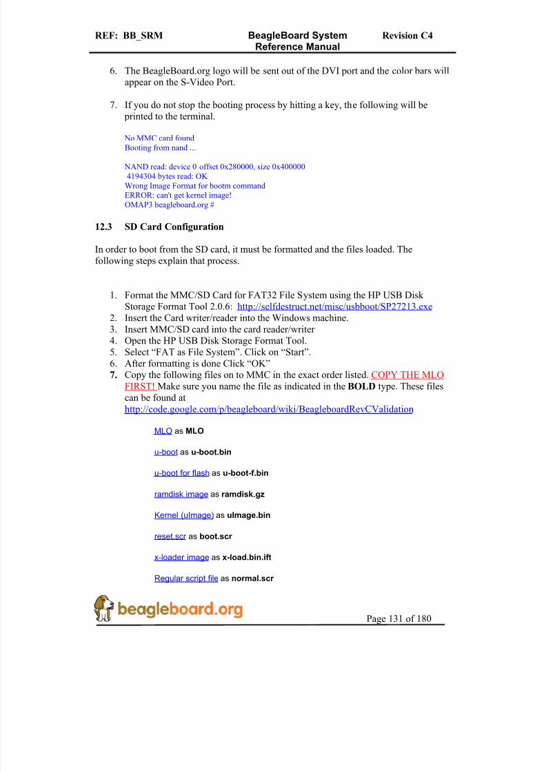
8/2/2019 Beagle Board Manual Rev. C4
http://slidepdf.com/reader/full/beagle-board-manual-rev-c4 131/180
REF: BB_SRM BeagleBoard SystemReference Manual
Revision C4
Page 131 of 180
6. The BeagleBoard.org logo will be sent out of the DVI port and the color bars willappear on the S-Video Port.
7. If you do not stop the booting process by hitting a key, the following will be printed to the terminal.
No MMC card foundBooting from nand ...
NAND read: device 0 offset 0x280000, size 0x4000004194304 bytes read: OK
Wrong Image Format for bootm commandERROR: can't get kernel image!OMAP3 beagleboard.org #
12.3 SD Card Configuration
In order to boot from the SD card, it must be formatted and the files loaded. Thefollowing steps explain that process.
1. Format the MMC/SD Card for FAT32 File System using the HP USB Disk Storage Format Tool 2.0.6: http://selfdestruct.net/misc/usbboot/SP27213.exe
2. Insert the Card writer/reader into the Windows machine.3. Insert MMC/SD card into the card reader/writer 4. Open the HP USB Disk Storage Format Tool.5. Select “FAT as File System”. Click on “Start”.6. After formatting is done Click “OK”
7. Copy the following files on to MMC in the exact order listed. COPY THE MLOFIRST! Make sure you name the file as indicated in the BOLD type. These filescan be found athttp://code.google.com/p/beagleboard/wiki/BeagleboardRevCValidation
MLO as MLO
u-boot as u-boot.bin
u-boot for flash as u-boot-f.bin
ramdisk image as ramdisk.gz
Kernel (uImage) as uImage.bin
reset.scr as boot.scr
x-loader image as x-load.bin.ift
Regular script file as normal.scr

8/2/2019 Beagle Board Manual Rev. C4
http://slidepdf.com/reader/full/beagle-board-manual-rev-c4 132/180
REF: BB_SRM BeagleBoard SystemReference Manual
Revision C4
Page 132 of 180
12.4 Setup
This step sets up the board for the tests to follow.
1. Make sure Beagle power is in OFF state by removing the 5V supply and the USB
host connection.2. Connect the IDC UART cable the BeagleBoard and using a Null-Modem serial
cable connect it to a SERIAL port on a Window/Linux/Mac machine3. Have terminal program, such as TeraTerm, HyperTerminal, or Minicom, running
on the host machine.4. Configure the terminal program for (BAUD RATE - 115200, DATA - 8 bit,
PARITY- none, STOP - 1bit, FLOW CONTROL - none)5. Insert the MMC/SD card (that is prepared as described above) into MMC/SD slot
on Beagle Board.6. Connect a LCD Monitor to DVI/HDMI port on the Beagle Board.7. Connect an externally powered speaker to audio out jack on Beagle Board.
8. Connect a Line-in cable from PC or any player to Audio In jack on Beagle Board.9. Connect a TV (NTSC-M) to S-video port.10. Power ON LCD, TV and audio speakers.
12.5 Factory Boot Verification
The BeagleBoard comes pre-Flashed with the Xloader and UBoot in Flash. This stepverifies that the board will boot properly from NAND. If the board has been flashed andthe default code removed or overwritten, then you should proceed to the next step.
1. Connect the USB cable to the Host PC,2. The power LED should come on.3. On the terminal window the following should be printed out by the BeagleBoard:
Texas Instruments X-Loader 1.4.2 (Feb 19 2009 - 12:01:24)Loading u-boot.bin from nand
U-Boot 2009.01-dirty (Feb 19 2009 - 12:22:31)
I2C: ready OMAP3530-GP rev 2, CPU-OPP2 L3-165MHz OMAP3 Beagle board + LPDDR/NANDDRAM: 256 MBNAND: 256 MiB*** Warning - bad CRC or NAND, using default environment
MUSB: using high speed In: serial usbtty Out: serial usbtty Err: serial usbtty

8/2/2019 Beagle Board Manual Rev. C4
http://slidepdf.com/reader/full/beagle-board-manual-rev-c4 133/180
REF: BB_SRM BeagleBoard SystemReference Manual
Revision C4
Page 133 of 180
Board revision C Serial #486000030000000004013f8a17019010 Hit any key to stop autoboot: 10 No MMC card found Booting from nand ...
NAND read: device 0 offset 0x280000, size 0x400000 4194304 bytes read: OK Wrong Image Format for bootm command ERROR: can't get kernel image! OMAP3 beagleboard.org # OMAP3 beagleboard.org #
4. The USER LEDS and the PMU LED should be on.5. The S-Video output should display color bars.6. The DVI-D monitor should display a solid orange screen.
12.6 Board SD Boot
This test will force the BeagleBoard to boot from the SD card instead of the onboardFlash.
1. Press and hold the USER button while pressing and releasing the RESET button.2. The following should be printed to the terminal window:
40V
Texas Instruments X-Loader 1.4.2 (Feb 19 2009 - 12:01:24)Reading boot sector Loading u-boot.bin from mmc
U-Boot 2009.01-dirty (Feb 19 2009 - 12:23:21)
I2C: readyOMAP3530-GP rev 2, CPU-OPP2 L3-165MHzOMAP3 Beagle board + LPDDR/NANDDRAM: 256 MBNAND: 256 MiBUsing default environment
MUSB: using high speedIn: serial usbttyOut: serial usbttyErr: serial usbttyBoard revision CSerial #486000030000000004013f8a17019010Hit any key to stop autoboot: 10
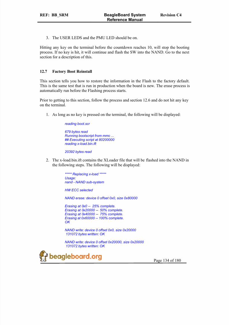
8/2/2019 Beagle Board Manual Rev. C4
http://slidepdf.com/reader/full/beagle-board-manual-rev-c4 134/180
REF: BB_SRM BeagleBoard SystemReference Manual
Revision C4
Page 134 of 180
3. The USER LEDS and the PMU LED should be on.
Hitting any key on the terminal before the countdown reaches 10, will stop the booting
process. If no key is hit, it will continue and flash the SW into the NAND. Go to the nextsection for a description of this.
12.7 Factory Boot Reinstall
This section tells you how to restore the information in the Flash to the factory default.This is the same test that is run in production when the board is new. The erase process isautomatically run before the Flashing process starts.
Prior to getting to this section, follow the process and section 12.6 and do not hit any key
on the terminal.
1. As long as no key is pressed on the terminal, the following will be displayed:
reading boot.scr
679 bytes read Running bootscript from mmc ...## Executing script at 80200000 reading x-load.bin.ift
20392 bytes read
2. The x-load.bin.ift contains the XLoader file that will be flashed into the NAND inthe following steps. The following will be displayed:
***** Replacing x-load ***** Usage:nand - NAND sub-system
HW ECC selected
NAND erase: device 0 offset 0x0, size 0x80000
Erasing at 0x0 -- 25% complete.Erasing at 0x20000 -- 50% complete.Erasing at 0x40000 -- 75% complete.Erasing at 0x60000 -- 100% complete.OK
NAND write: device 0 offset 0x0, size 0x20000 131072 bytes written: OK
NAND write: device 0 offset 0x20000, size 0x20000 131072 bytes written: OK

8/2/2019 Beagle Board Manual Rev. C4
http://slidepdf.com/reader/full/beagle-board-manual-rev-c4 135/180
REF: BB_SRM BeagleBoard SystemReference Manual
Revision C4
Page 135 of 180
NAND write: device 0 offset 0x40000, size 0x20000 131072 bytes written: OK
NAND write: device 0 offset 0x60000, size 0x20000 131072 bytes written: OK
3. The u-boot-f.bin contains the UBoot file that will be flashed into the NAND in thefollowing steps. The following will be displayed:
reading u-boot-f.bin
275928 bytes read ***** Replacing u-boot ***** Usage:nand - NAND sub-system
SW ECC selected
NAND erase: device 0 offset 0x80000, size 0x160000
Erasing at 0x80000 -- 9% complete.Erasing at 0xa0000 -- 18% complete.Erasing at 0xc0000 -- 27% complete.Erasing at 0xe0000 -- 36% complete.Erasing at 0x100000 -- 45% complete.Erasing at 0x120000 -- 54% complete.Erasing at 0x140000 -- 63% complete.Erasing at 0x160000 -- 72% complete.Erasing at 0x180000 -- 81% complete.Erasing at 0x1a0000 -- 90% complete.Erasing at 0x1c0000 -- 100% complete.
OK
NAND write: device 0 offset 0x80000, size 0x160000 1441792 bytes written: OK
4. After the XLoader and UBot are flashed, the environment variables are erased toinsure proper booting of the Kernel image that I son the SD card. . The followingwill be displayed:
***** Erasing environment settings ***** Usage:nand - NAND sub-system
NAND erase: device 0 offset 0x160000, size 0x20000
Erasing at 0x160000 -- 100% complete.OK

8/2/2019 Beagle Board Manual Rev. C4
http://slidepdf.com/reader/full/beagle-board-manual-rev-c4 136/180
REF: BB_SRM BeagleBoard SystemReference Manual
Revision C4
Page 136 of 180
5. At this point you can remove power to stop the Kernel from booting, or just let itcontinue the Kernel boot process. For information on the Kernel booting process, proceed to the next section.
12.8 Booting the Kernel
This section describes how to boot the kernel from the SD card. In order to complete thissection, you must have completed section 12.7 and do not hit any keys or remove power after the NAND has been flashed.
1. After the NAND has been flashed, the normal.scr script is read form the SD cardand the first step after that is to load in the uImage.bin file into the SDRAM.Beagle will print the following to the terminal:
***** Executing normal.scr *****
## Executing script at 80200000reading uImage.bin
2578044 bytes read***** Kernel: /dev/mmcblk0p1/uImage.bin *****
2. Then the root filesystem is read into SDRAM. The BeagleBoard will output thefollowing:
reading ramdisk.gz
7999649 bytes read ***** RootFS: /dev/mmcblk0p1/ramdisk.gz ***** 1856680 bytes read
3. At this point, the booting process will start. The following will be printed to theterminal:
## Booting kernel from Legacy Image at 80200000 ...Image Name: Linux-2.6.28-omap1Image Type: ARM Linux Kernel Image (uncompressed)Data Size: 2577980 Bytes = 2.5 MBLoad Address: 80008000 Entry Point: 80008000 Verifying Checksum ... OK Loading Kernel Image ... OK
OK
Starting kernel ...
Uncompressing Linux..................................................................................................................................................................... done, booting the kernel.
Linux version 2.6.28-omap1 (root@tiioss) (gcc version 4.2.1 (CodeSourcery Sourcery G++ Lite2007q3-51)) #2 Thu Feb 19 12:45:34 IST 2009CPU: ARMv7 Processor [411fc083] revision 3 (ARMv7), cr=10c5387f CPU: VIPT nonaliasing data cache, VIPT nonaliasing instruction cache

8/2/2019 Beagle Board Manual Rev. C4
http://slidepdf.com/reader/full/beagle-board-manual-rev-c4 137/180
REF: BB_SRM BeagleBoard SystemReference Manual
Revision C4
Page 137 of 180
Machine: OMAP3 Beagle Board Memory policy: ECC disabled, Data cache writeback OMAP3430 ES3.0 SRAM: Mapped pa 0x40200000 to va 0xd7000000 size: 0x100000 Reserving 15728640 bytes SDRAM for VRAM Built 1 zonelists in Zone order, mobility grouping on. Total pages: 65024Kernel command line: console=ttyS2,115200n8 console=tty0 root=/dev/ram0 rw ramdisk_size=32768 initrd=0x81600000,32M Clocking rate (Crystal/DPLL/ARM core): 26.0/332/500 MHz GPMC revision 5.0 IRQ: Found an INTC at 0xd8200000 (revision 4.0) with 96 interruptsTotal of 96 interrupts on 1 active controller OMAP34xx GPIO hardware version 2.5 PID hash table entries: 1024 (order: 10, 4096 bytes)OMAP clockevent source: GPTIMER12 at 32768 Hz Console: colour dummy device 80x30 console [tty0] enabled Dentry cache hash table entries: 32768 (order: 5, 131072 bytes)Inode-cache hash table entries: 16384 (order: 4, 65536 bytes)Memory: 128MB 128MB = 256MB total Memory: 206080KB available (4776K code, 425K data, 168K init)Calibrating delay loop... 473.71 BogoMIPS (lpj=1851392)Mount-cache hash table entries: 512CPU: Testing write buffer coherency: ok
net_namespace: 532 bytesregulator: core version 0.5 NET: Registered protocol family 16 Found NAND on CS0 Registering NAND on CS0 OMAP DMA hardware revision 4.0 USB: No board-specific platform config found OMAP DSS rev 2.0 OMAP DISPC rev 3.0 OMAP VENC rev 2OMAP DSI rev 1.0 i2c_omap i2c_omap.1: bus 1 rev3.12 at 2600 kHz twl4030: PIH (irq 7) chaining IRQs 368..375 twl4030: power (irq 373) chaining IRQs 376..383twl4030: gpio (irq 368) chaining IRQs 384..401i2c_omap i2c_omap.3: bus 3 rev3.12 at 400 kHz SCSI subsystem initialized
twl4030_usb twl4030_usb: Initialized TWL4030 USB moduleusbcore: registered new interface driver usbfsusbcore: registered new interface driver hubusbcore: registered new device driver usbmusb_hdrc: version 6.0, musb-dma, otg (peripheral+host), debug=0 musb_hdrc: USB OTG mode controller at d80ab000 using DMA, IRQ 92regulator: VMMC1: 1850 <--> 3150 mV normal standby regulator: VDAC: 1800 mV normal standby
regulator: VUSB1V5: 1500 mV normal standby regulator: VUSB1V8: 1800 mV normal standby regulator: VUSB3V1: 3100 mV normal standby regulator: VSIM: 1800 <--> 3000 mV normal standby Bluetooth: Core ver 2.13NET: Registered protocol family 31Bluetooth: HCI device and connection manager initialized
Bluetooth: HCI socket layer initialized cfg80211: Using static regulatory domain infocfg80211: Regulatory domain: US
(start_freq - end_freq @ bandwidth), (max_antenna_gain, max_eirp)(2402000 KHz - 2472000 KHz @ 40000 KHz), (600 mBi, 2700 mBm)(5170000 KHz - 5190000 KHz @ 40000 KHz), (600 mBi, 2300 mBm)(5190000 KHz - 5210000 KHz @ 40000 KHz), (600 mBi, 2300 mBm)(5210000 KHz - 5230000 KHz @ 40000 KHz), (600 mBi, 2300 mBm)(5230000 KHz - 5330000 KHz @ 40000 KHz), (600 mBi, 2300 mBm)(5735000 KHz - 5835000 KHz @ 40000 KHz), (600 mBi, 3000 mBm)
cfg80211: Calling CRDA for country: US

8/2/2019 Beagle Board Manual Rev. C4
http://slidepdf.com/reader/full/beagle-board-manual-rev-c4 138/180
REF: BB_SRM BeagleBoard SystemReference Manual
Revision C4
Page 138 of 180
NET: Registered protocol family 2IP route cache hash table entries: 2048 (order: 1, 8192 bytes)TCP established hash table entries: 8192 (order: 4, 65536 bytes)TCP bind hash table entries: 8192 (order: 3, 32768 bytes)
TCP: Hash tables configured (established 8192 bind 8192)TCP reno registered NET: Registered protocol family 1checking if image is initramfs...it isn't (no cpio magic); looks like an initrd Freeing initrd memory: 32768K VFS: Disk quotas dquot_6.5.1Dquot-cache hash table entries: 1024 (order 0, 4096 bytes)JFFS2 version 2.2. (NAND) (SUMMARY) © 2001-2006 Red Hat, Inc.msgmni has been set to 467 alg: No test for stdrng (krng)io scheduler noop registered io scheduler anticipatory registered io scheduler deadline registered io scheduler cfq registered (default)Serial: 8250/16550 driver4 ports, IRQ sharing enabled serial8250.0: ttyS0 at MMIO 0x4806a000 (irq = 72) is a ST16654serial8250.0: ttyS1 at MMIO 0x4806c000 (irq = 73) is a ST16654serial8250.0: ttyS2 at MMIO 0x49020000 (irq = 74) is a ST16654console [ttyS2] enabled
brd: module loaded loop: module loaded usbcore: registered new interface driver asix usbcore: registered new interface driver cdc_ether usbcore: registered new interface driver rndis_host usbcore: registered new interface driver zd1211rw usbcore: registered new interface driver rndis_wlanusbcore: registered new interface driver zd1201usbcore: registered new interface driver usb8xxx usbcore: registered new interface driver rtl8187 usbcore: registered new interface driver rt2500usbusbcore: registered new interface driver rt73usbusbcore: registered new interface driver p54usbi2c /dev entries driver input: triton2-pwrbutton as /class/input/input0 triton2 power button driver initialized Driver 'sd' needs updating - please use bus_type methods
Driver 'sr' needs updating - please use bus_type methodsomap2-nand driver initializing NAND device: Manufacturer ID: 0x2c, Chip ID: 0xba (Micron NAND 256MiB 1,8V 16-bit)cmdlinepart partition parsing not availableCreating 5 MTD partitions on "omap2-nand":0x00000000-0x00080000 : "X-Loader" 0x00080000-0x00260000 : "U-Boot" 0x00260000-0x00280000 : "U-Boot Env" 0x00280000-0x00680000 : "Kernel" 0x00680000-0x10000000 : "File System" ehci_hcd: USB 2.0 'Enhanced' Host Controller (EHCI) Driver ehci-omap ehci-omap.0: OMAP-EHCI Host Controller ehci-omap ehci-omap.0: new USB bus registered, assigned bus number 1ehci-omap ehci-omap.0: irq 77, io mem 0x48064800 ehci-omap ehci-omap.0: USB 2.0 started, EHCI 1.00 usb usb1: configuration #1 chosen from 1 choice
hub 1-0:1.0: USB hub found hub 1-0:1.0: 3 ports detected Initializing USB Mass Storage driver...usbcore: registered new interface driver usb-storageUSB Mass Storage support registered.g_ether gadget: using random self ethernet addressg_ether gadget: using random host ethernet addressusb0: MAC 22:46:4b:c2:b0:fb
usb0: HOST MAC a2:b4:44:63:f6:aeg_ether gadget: Ethernet Gadget, version: Memorial Day 2008 g_ether gadget: g_ether ready

8/2/2019 Beagle Board Manual Rev. C4
http://slidepdf.com/reader/full/beagle-board-manual-rev-c4 139/180
REF: BB_SRM BeagleBoard SystemReference Manual
Revision C4
Page 139 of 180
musb_hdrc musb_hdrc: MUSB HDRC host driver musb_hdrc musb_hdrc: new USB bus registered, assigned bus number 2usb usb2: configuration #1 chosen from 1 choicehub 2-0:1.0: USB hub found hub 2-0:1.0: 1 port detected mice: PS/2 mouse device common for all miceinput: gpio-keys as /class/input/input1twl4030_rtc twl4030_rtc: rtc core: registered twl4030_rtc as rtc0 twl4030_rtc twl4030_rtc: Power up reset detected.twl4030_rtc twl4030_rtc: Enabling TWL4030-RTC.OMAP Watchdog Timer Rev 0x31: initial timeout 60 sec Bluetooth: HCI USB driver ver 2.10 usbcore: registered new interface driver hci_usbBluetooth: Broadcom Blutonium firmware driver ver 1.2usbcore: registered new interface driver bcm203x Bluetooth: Digianswer Bluetooth USB driver ver 0.10 usbcore: registered new interface driver bpa10x Bluetooth: Generic Bluetooth SDIO driver ver 0.1mmci-omap-hs mmci-omap-hs.0: Failed to get debounce clock Registered led device: beagleboard::usr0 Registered led device: beagleboard::usr1leds-gpio: probe of leds-gpio failed with error -22usbcore: registered new interface driver usbhid
usbhid: v2.6:USB HID core driver Advanced Linux Sound Architecture Driver Version 1.0.18rc3.usbcore: registered new interface driver snd-usb-audio
ASoC version 0.13.2OMAP3 Beagle SoC init TWL4030 Audio Codec init asoc: twl4030 <-> omap-mcbsp-dai-(link_id) mapping ok
ALSA device list:#0: omap3beagle (twl4030)
oprofile: using arm/armv7 TCP cubic registered NET: Registered protocol family 17
NET: Registered protocol family 15 Bluetooth: L2CAP ver 2.11Bluetooth: L2CAP socket layer initialized Bluetooth: SCO (Voice Link) ver 0.6
Bluetooth: SCO socket layer initialized Bluetooth: RFCOMM socket layer initialized Bluetooth: RFCOMM TTY layer initialized Bluetooth: RFCOMM ver 1.10 Bluetooth: BNEP (Ethernet Emulation) ver 1.3Bluetooth: BNEP filters: protocol multicast Bluetooth: HIDP (Human Interface Emulation) ver 1.2RPC: Registered udp transport module.RPC: Registered tcp transport module.ieee80211: 802.11 data/management/control stack, git-1.1.13ieee80211: Copyright (C) 2004-2005 Intel Corporation <[email protected]>ThumbEE CPU extension supported.Power Management for TI OMAP3.SmartReflex driver initialized Disabling unused clock "sr2_fck" Disabling unused clock "sr1_fck"
Disabling unused clock "mcbsp_fck" Disabling unused clock "mcbsp_fck" Disabling unused clock "mcbsp_fck" Disabling unused clock "mcbsp_ick" Disabling unused clock "mcbsp_ick" Disabling unused clock "mcbsp_ick" Disabling unused clock "gpt2_ick" Disabling unused clock "gpt3_ick" Disabling unused clock "gpt4_ick" Disabling unused clock "gpt5_ick" Disabling unused clock "gpt6_ick" Disabling unused clock "gpt7_ick"

8/2/2019 Beagle Board Manual Rev. C4
http://slidepdf.com/reader/full/beagle-board-manual-rev-c4 140/180
REF: BB_SRM BeagleBoard SystemReference Manual
Revision C4
Page 140 of 180
Disabling unused clock "gpt8_ick" Disabling unused clock "gpt9_ick" Disabling unused clock "wdt3_ick" Disabling unused clock "wdt3_fck" Disabling unused clock "gpio2_dbck" Disabling unused clock "gpio3_dbck" Disabling unused clock "gpio4_dbck" Disabling unused clock "gpio5_dbck" Disabling unused clock "gpio6_dbck" Disabling unused clock "gpt9_fck" Disabling unused clock "gpt8_fck" Disabling unused clock "gpt7_fck" Disabling unused clock "gpt6_fck" Disabling unused clock "gpt5_fck" Disabling unused clock "gpt4_fck" Disabling unused clock "gpt3_fck" Disabling unused clock "gpt2_fck" Disabling unused clock "gpt1_ick" Disabling unused clock "wdt1_ick" Disabling unused clock "wdt2_ick" Disabling unused clock "wdt2_fck" Disabling unused clock "gpio1_dbck" Disabling unused clock "gpt1_fck" Disabling unused clock "cam_ick"
Disabling unused clock "cam_mclk" Disabling unused clock "des1_ick"
Disabling unused clock "sha11_ick" Disabling unused clock "rng_ick"
Disabling unused clock "aes1_ick" Disabling unused clock "ssi_ick" Disabling unused clock "mailboxes_ick" Disabling unused clock "mcbsp_ick" Disabling unused clock "mcbsp_ick" Disabling unused clock "gpt10_ick" Disabling unused clock "gpt11_ick" Disabling unused clock "i2c_ick" Disabling unused clock "mcspi_ick" Disabling unused clock "mcspi_ick"
Disabling unused clock "mcspi_ick" Disabling unused clock "mcspi_ick" Disabling unused clock "hdq_ick" Disabling unused clock "mspro_ick" Disabling unused clock "des2_ick" Disabling unused clock "sha12_ick" Disabling unused clock "aes2_ick" Disabling unused clock "icr_ick" Disabling unused clock "pka_ick" Disabling unused clock "ssi_ssr_fck" Disabling unused clock "hdq_fck" Disabling unused clock "mcspi_fck" Disabling unused clock "mcspi_fck" Disabling unused clock "mcspi_fck" Disabling unused clock "mcspi_fck" Disabling unused clock "mcbsp_fck"
Disabling unused clock "mcbsp_fck" Disabling unused clock "i2c_fck" Disabling unused clock "mspro_fck" Disabling unused clock "gpt11_fck" Disabling unused clock "gpt10_fck" Disabling unused clock "dpll4_m6x2_ck" Disabling unused clock "dpll3_m3x2_ck" Disabling unused clock "sys_clkout1" VFP support v0.3: implementor 41 architecture 3 part 30 variant c rev 1Console: switching to colour frame buffer device 80x30 clock: clksel_round_rate_div: dpll4_m4_ck target_rate 48000000 clock: new_div = 9, new_rate = 48000000
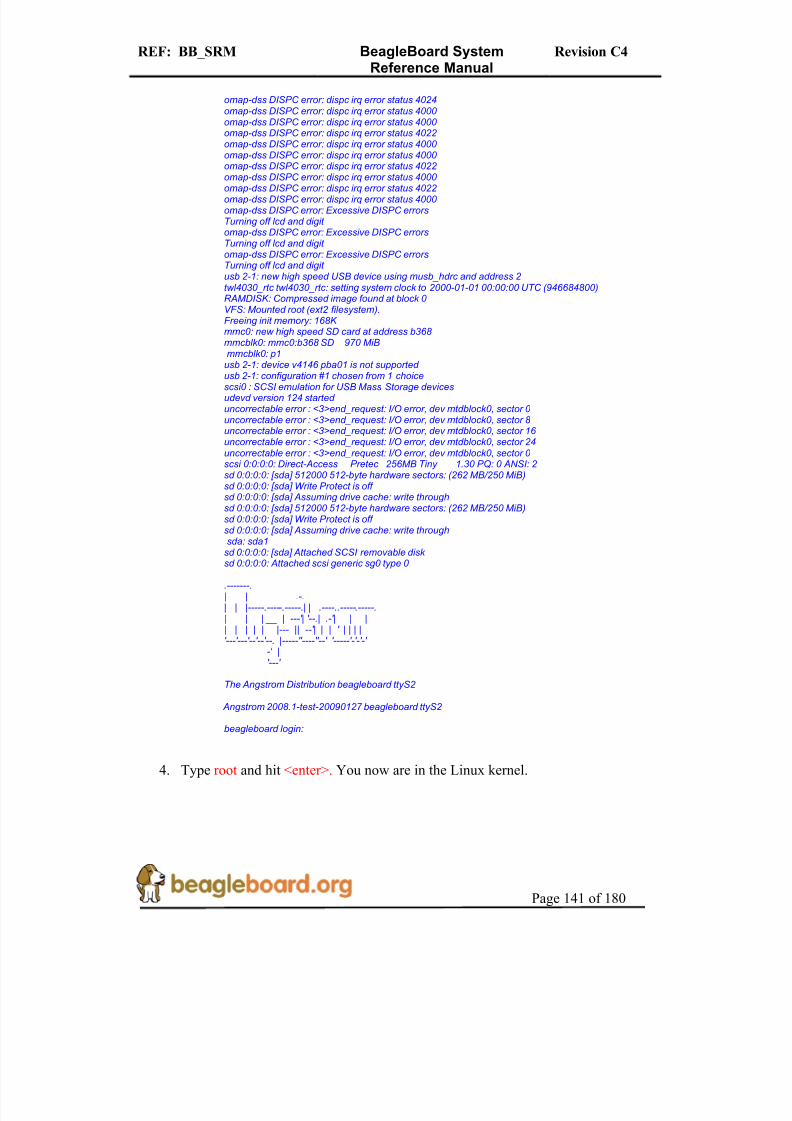
8/2/2019 Beagle Board Manual Rev. C4
http://slidepdf.com/reader/full/beagle-board-manual-rev-c4 141/180
REF: BB_SRM BeagleBoard SystemReference Manual
Revision C4
Page 141 of 180
omap-dss DISPC error: dispc irq error status 4024omap-dss DISPC error: dispc irq error status 4000 omap-dss DISPC error: dispc irq error status 4000 omap-dss DISPC error: dispc irq error status 4022omap-dss DISPC error: dispc irq error status 4000 omap-dss DISPC error: dispc irq error status 4000 omap-dss DISPC error: dispc irq error status 4022omap-dss DISPC error: dispc irq error status 4000 omap-dss DISPC error: dispc irq error status 4022omap-dss DISPC error: dispc irq error status 4000 omap-dss DISPC error: Excessive DISPC errorsTurning off lcd and digit omap-dss DISPC error: Excessive DISPC errorsTurning off lcd and digit omap-dss DISPC error: Excessive DISPC errorsTurning off lcd and digit usb 2-1: new high speed USB device using musb_hdrc and address 2twl4030_rtc twl4030_rtc: setting system clock to 2000-01-01 00:00:00 UTC (946684800)RAMDISK: Compressed image found at block 0 VFS: Mounted root (ext2 filesystem).Freeing init memory: 168K mmc0: new high speed SD card at address b368 mmcblk0: mmc0:b368 SD 970 MiBmmcblk0: p1
usb 2-1: device v4146 pba01 is not supported usb 2-1: configuration #1 chosen from 1 choicescsi0 : SCSI emulation for USB Mass Storage devicesudevd version 124 started uncorrectable error : <3>end_request: I/O error, dev mtdblock0, sector 0 uncorrectable error : <3>end_request: I/O error, dev mtdblock0, sector 8 uncorrectable error : <3>end_request: I/O error, dev mtdblock0, sector 16 uncorrectable error : <3>end_request: I/O error, dev mtdblock0, sector 24uncorrectable error : <3>end_request: I/O error, dev mtdblock0, sector 0 scsi 0:0:0:0: Direct-Access Pretec 256MB Tiny 1.30 PQ: 0 ANSI: 2sd 0:0:0:0: [sda] 512000 512-byte hardware sectors: (262 MB/250 MiB)sd 0:0:0:0: [sda] Write Protect is off sd 0:0:0:0: [sda] Assuming drive cache: write throughsd 0:0:0:0: [sda] 512000 512-byte hardware sectors: (262 MB/250 MiB)sd 0:0:0:0: [sda] Write Protect is off sd 0:0:0:0: [sda] Assuming drive cache: write throughsda: sda1
sd 0:0:0:0: [sda] Attached SCSI removable disk sd 0:0:0:0: Attached scsi generic sg0 type 0
.-------.| | .-.| | |-----.-----.-----.| | .----..-----.-----.| | | __ | ---'| '--.| .-'| | || | | | | |--- || --'| | | ' | | | |'---'---'--'--'--. |-----''----''--' '-----'-'-'-'
-' |'---'
The Angstrom Distribution beagleboard ttyS2
Angstrom 2008.1-test-20090127 beagleboard ttyS2
beagleboard login:
4. Type root and hit <enter>. You now are in the Linux kernel.

8/2/2019 Beagle Board Manual Rev. C4
http://slidepdf.com/reader/full/beagle-board-manual-rev-c4 142/180

8/2/2019 Beagle Board Manual Rev. C4
http://slidepdf.com/reader/full/beagle-board-manual-rev-c4 143/180

8/2/2019 Beagle Board Manual Rev. C4
http://slidepdf.com/reader/full/beagle-board-manual-rev-c4 144/180
REF: BB_SRM BeagleBoard SystemReference Manual
Revision C4
Page 144 of 180
2. Type the following command to start the video:
[root@beagleboard:/mmc# mplayer /sample_video.avi
3. It will display a 320x240 video on the DVI screen. The video has beendownloaded from https://garage.maemo.org/download.php/54/269/2380/bug.avi
12.10.3 Audio Test
The audio test is divided into two test, one for audio in and one for audio out. Audio isrecorded into the audio in port and then played out the audio out port.
12.10.3.1 Audio In
1. Make Sure your player is running and Audio Line in is connected to board.2. Make sure that you are in the MMC directory. If you are, proceed to step 4. If not,then type the following command:
root@beagleboard:~# mkdir /mmc root@beagleboard:~# mount -t vfat /dev/mmcblk0p1 /mmc
3. Change the directory by typing:
root@beagleboard:/mmc# cd /mmc
4. Type the following command:
root@beagleboard:/mmc# arecord -t wav -c 2 -r 44100 -f S16_LE -v /mmc/k
5. The following output is expected on the terminal window:
Recording WAVE '/mmc/k' : Signed 16 bit Little Endian, Rate 44100 Hz, StereoPlug PCM: Hardware PCM card 0 'omap3beagle' device 0 subdevice 0Its setup is:
stream : CAPTUREaccess : RW_INTERLEAVEDformat : S16_LEsubformat : STDchannels : 2rate : 44100
exact rate : 44100 (44100/1)msbits : 16buffer_size : 22052period_size : 5513period_time : 125011tstamp_mode : NONEperiod_step : 1avail_min : 5513period_event : 0

8/2/2019 Beagle Board Manual Rev. C4
http://slidepdf.com/reader/full/beagle-board-manual-rev-c4 145/180
REF: BB_SRM BeagleBoard SystemReference Manual
Revision C4
Page 145 of 180
start_threshold : 1stop_threshold : 22052silence_threshold: 0silence_size : 0boundary : 1445199872
6. When you want to stop the recording process just press <CONTROL+C>.
12.10.3.2 Audio Out
NOTE: It is expected that you have previously recorded an audio file to be played andthat you are still in the MMC directory.
1. Type the following command:root@beagleboard:/mmc# aplay -t wav -c 2 -r 44100 -f S16_LE -v k
2. The recorded audio should be heard on the Speakers,
3. The following output is expected on terminal window:
Playing WAVE '/mmc/k' : Signed 16 bit Little Endian, Rate 44100 Hz, StereoPlug PCM: Hardware PCM card 0 'omap3beagle' device 0 subdevice 0Its setup is:
stream : PLAYBACKaccess : RW_INTERLEAVED
format : S16_LEsubformat : STDchannels : 2
rate : 44100exact rate : 44100 (44100/1)msbits : 16buffer_size : 22052period_size : 5513period_time : 125011tstamp_mode : NONEperiod_step : 1avail_min : 5513period_event : 0start_threshold : 22052stop_threshold : 22052silence_threshold: 0
silence_size : 0boundary : 1445199872
7. To stop the audio playback just press <CONTROL+C>. If you choose, you can the letthe recorded audio play out. It will stop when it reaches the end of the recorded file.

8/2/2019 Beagle Board Manual Rev. C4
http://slidepdf.com/reader/full/beagle-board-manual-rev-c4 146/180
REF: BB_SRM BeagleBoard SystemReference Manual
Revision C4
Page 146 of 180
12.10.3.3 Keyboard Test
This test runs on the OTG port in the Host mode. It requires that a Powered USB hub beused, and that the Hub and device (Keyboard or mouse) be connected when the Linux OSis booted. This section is broken down into two sections, one for the mouse and the other
for the keyboard.
NOTE: This test is run after the OS is booted with the Hub and Keyboard plugged
in.
1. Make sure that you are in the MMC directory. If you are, proceed to step 3. If not,then type the following command:
root@beagleboard:~]# mkdir /mmc root@beagleboard:~]# mount -t vfat /dev/mmcblk0p1 /mnt/mmc/cd /mnt/mmc/
2. Change the directory by typing:
root@beagleboard:~# cd /mmc
3. Type the following command:
root@beagleboard:/mmc]# evtest /dev/input/event1
4. Press a Key on USB Keyboard and look for a printout in the terminal window.
Example if "a" is pressed the following output is seen on Console:
Event: time 1657.754638, type 1 (Key), code 30 (A), value 1
Event: time 1657.754638, -------------- Report Sync ------------Event: time 1657.964599, type 1 (Key), code 30 (A), value 0Event: time 1657.964599, -------------- Report Sync ------------
5. Press <CONTROL+C> to stop the test.
12.10.3.4 Mouse Test
NOTE: This test is run after the Kernel booted with the Hub and mouse plugged in.
1. Make sure that you are in the MMC directory. If you are, proceed to step 3. If not,then type the following command:
root@beagleboard:~# mount -t vfat /dev/mmcblk0p1 /mmc/
2. Change the directory by typing:
root@beagleboard:~# cd /mnt/mmc/
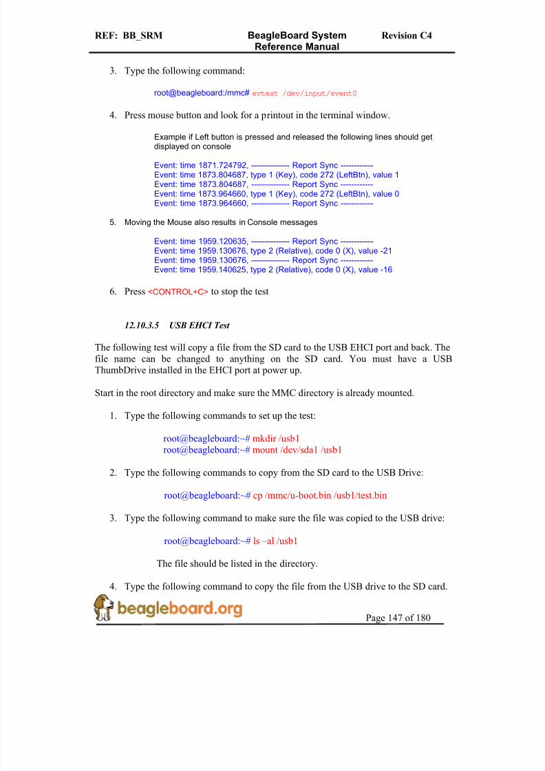
8/2/2019 Beagle Board Manual Rev. C4
http://slidepdf.com/reader/full/beagle-board-manual-rev-c4 147/180
REF: BB_SRM BeagleBoard SystemReference Manual
Revision C4
Page 147 of 180
3. Type the following command:
root@beagleboard:/mmc# evtest /dev/input/event0
4. Press mouse button and look for a printout in the terminal window.
Example if Left button is pressed and released the following lines should getdisplayed on console
Event: time 1871.724792, -------------- Report Sync ------------Event: time 1873.804687, type 1 (Key), code 272 (LeftBtn), value 1Event: time 1873.804687, -------------- Report Sync ------------Event: time 1873.964660, type 1 (Key), code 272 (LeftBtn), value 0Event: time 1873.964660, -------------- Report Sync ------------
5. Moving the Mouse also results in Console messages
Event: time 1959.120635, -------------- Report Sync ------------
Event: time 1959.130676, type 2 (Relative), code 0 (X), value -21Event: time 1959.130676, -------------- Report Sync ------------Event: time 1959.140625, type 2 (Relative), code 0 (X), value -16
6. Press <CONTROL+C> to stop the test
12.10.3.5 USB EHCI Test
The following test will copy a file from the SD card to the USB EHCI port and back. Thefile name can be changed to anything on the SD card. You must have a USBThumbDrive installed in the EHCI port at power up.
Start in the root directory and make sure the MMC directory is already mounted.
1. Type the following commands to set up the test:
root@beagleboard:~# mkdir /usb1 root@beagleboard:~# mount /dev/sda1 /usb1
2. Type the following commands to copy from the SD card to the USB Drive:
root@beagleboard:~# cp /mmc/u-boot.bin /usb1/test.bin
3. Type the following command to make sure the file was copied to the USB drive:
root@beagleboard:~# ls –al /usb1
The file should be listed in the directory.
4. Type the following command to copy the file from the USB drive to the SD card.

8/2/2019 Beagle Board Manual Rev. C4
http://slidepdf.com/reader/full/beagle-board-manual-rev-c4 148/180
REF: BB_SRM BeagleBoard SystemReference Manual
Revision C4
Page 148 of 180
root@beagleboard:~# cp /usb1/test.bin /mmc1/test.bin
5. Type the following command to copy to make sure the file was copied to the SDcard.
root@beagleboard:~# ls –al /mmc
The file should be listed in the directory. Larger files can be used to create a longer test if desired.
13.0 Troubleshooting
This section will provide assistance in troubleshooting the BeagleBoard in the event there
are questions raised as to what the sate of the BeagleBoard is. This may be due to a HWfailure or the SW not initializing things properly during development. Also provided is asection of know issues. Be sure and check with BeagleBoard.org for any updates.
For an up to date listing of common questions and their answers, please refer tohttp://elinux.org/BeagleBoardFAQ
13.1 Access Points
This section covers the various access points where various signals and voltages can bemeasured.
13.1.1 Voltage Points
Figure 81 shows the test points for the various voltages on BeagleBoard.

8/2/2019 Beagle Board Manual Rev. C4
http://slidepdf.com/reader/full/beagle-board-manual-rev-c4 149/180
REF: BB_SRM BeagleBoard SystemReference Manual
Revision C4
Page 149 of 180
Figure 78. BeagleBoard Voltage Access Points
Some of these voltages may not be present depending on the state of the TWL4030 as set by the OMAP3530. Others may be at different voltage levels depending on the same
factor.
Table 40 provides the ranges of the voltages and the definition of the conditions asapplicable.
C4
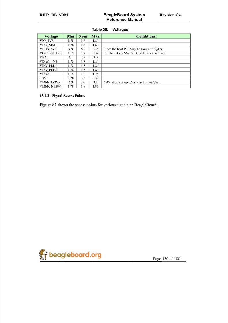
8/2/2019 Beagle Board Manual Rev. C4
http://slidepdf.com/reader/full/beagle-board-manual-rev-c4 150/180
REF: BB_SRM BeagleBoard SystemReference Manual
Revision C4
Page 150 of 180
Table 39. Voltages
Voltage Min Nom Max ConditionsVIO_1V8 1.78 1.8 1.81
VDD_SIM 1.78 1.8 1.81
VBUS_5V0 4.9 5.0 5.2 From the host PC. May be lower or higher.
VOCORE_1V3 1.15 1.2 1.4 Can be set via SW. Voltage levels may vary.VBAT 4.1 4.2 4.3
VDAC_1V8 1.78 1.8 1.81
VDD_PLL1 1.78 1.8 1.81
VDD_PLL2 1.78 1.8 1.81
VDD2 1.15 1.2 1.25
3.3V 3.28 3.3 3.32
VMMC1 (3V) 2.9 3.0 3.1 3.0V at power up. Can be set to via SW.
VMMC1(1.8V) 1.78 1.8 1.81
13.1.2 Signal Access Points
Figure 82 shows the access points for various signals on BeagleBoard.
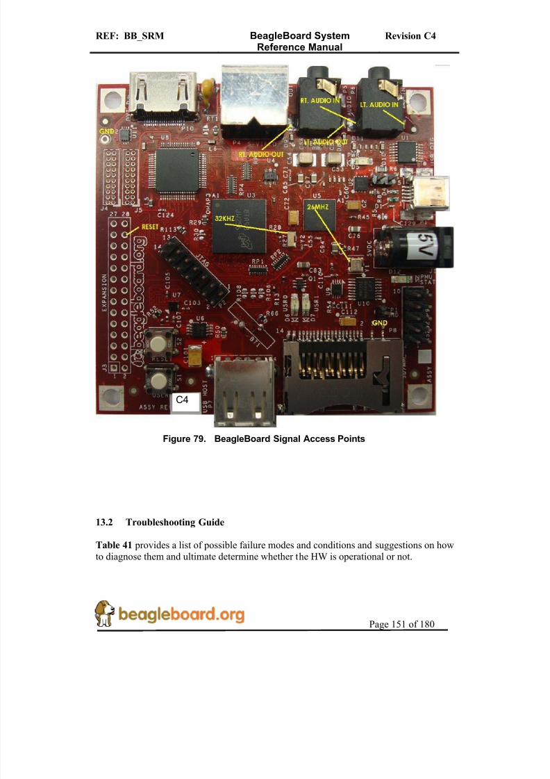
8/2/2019 Beagle Board Manual Rev. C4
http://slidepdf.com/reader/full/beagle-board-manual-rev-c4 151/180
REF: BB_SRM BeagleBoard SystemReference Manual
Revision C4
Page 151 of 180
Figure 79. BeagleBoard Signal Access Points
13.2 Troubleshooting Guide
Table 41 provides a list of possible failure modes and conditions and suggestions on howto diagnose them and ultimate determine whether the HW is operational or not.
C4

8/2/2019 Beagle Board Manual Rev. C4
http://slidepdf.com/reader/full/beagle-board-manual-rev-c4 152/180
REF: BB_SRM BeagleBoard SystemReference Manual
Revision C4
Page 152 of 180
Table 40. Troubleshooting
Symptoms Possible Problem Action
Verify that the Power LED ison.
If off and running over USB,the PC may have shut down
the voltage due to excessivecurrent as related to what it iscapable of providing. Removethe USB cable and re insert.
If running on a DC supplymake sure that voltage is beingsupplied.
JTAG does not connect.
JTAG interface needs to bereset
Reset the BeagleBoard.
Verify orientation of the
RS232 flat cable
Incorrect serial cable
configuration. Check for the right nullmodem cable.
Make sure the SD/MMC cardis installed all they way intothe connector.
UBoot does not start,and no activity on the
RS232 monitor.
If a 40V is displayed over theserial cable, processor is booting. Issue could be theSD/MMC card. Make sure the card is
formatted correctly and thatthe MLO file is the first filewritten to the SD card.
USB Host Connection
Issues via OTG.
Cheap USB Cable. OTG
cables are typically notdesigned for higher current.The expect 100mA max.
Measure the voltage at the card
to determine the voltage dropacross the cable. If it the levelis below 4.35V, the USB power is not guaranteed towork,
13.3 Serial Port Issues
We have had several serial port issues in the field caused by different issues. This section
attempts to provide a step by step process to identify what the issue is.
The main thing to keep in mind is that the PC and the BeagleBoard connectors are wiredthe same. In order for them to talk, they must have a null modem cable to connect them.
The following sections provide steps to help identify the issue.

8/2/2019 Beagle Board Manual Rev. C4
http://slidepdf.com/reader/full/beagle-board-manual-rev-c4 153/180

8/2/2019 Beagle Board Manual Rev. C4
http://slidepdf.com/reader/full/beagle-board-manual-rev-c4 154/180
REF: BB_SRM BeagleBoard SystemReference Manual
Revision C4
Page 154 of 180
Figure 81. DB9 Male Connector
Figure 82. DB9 Null Modem Cable
4. If you have an ohmmeter, you can measure to see if the pins are swapped between pins 2 and 3 from each end of the cable.
13.3.2 Second Step
A simple test to verify that the cables you are using are correct to create a loopback onthe cable. This checks the IDC cable and the null modem cable for connections.
1. Connect a wire across the TX and RX leads (Pins 2 and Pins 3) of the cable that plugs into the BeagleBoard (IDC Cable). Figure 86 shows how this is done.

8/2/2019 Beagle Board Manual Rev. C4
http://slidepdf.com/reader/full/beagle-board-manual-rev-c4 155/180
REF: BB_SRM BeagleBoard SystemReference Manual
Revision C4
Page 155 of 180
Figure 83. Serial Cable Loopback
2. On your terminal start typing. 3. If the correct characters are echoed back, then the cables are in the proper
configuration. Note that this checks the electrical connection only. If the terminal
program is set wrong, then serial port will still not work.
13.3.3 Third Step
1. Make sure your terminal settings are correct.
o BAUD RATE: 115200o DATA: 8 bito PARITY: noneo STOP: 1bit
o FLOW CONTROL: none (Critical)
Make sure that the Flow Control is set to none.
13.3.4 Fourth Step
If everything checks out OK on the previous steps, then the issue may be on theBeagleBoard. Follow the steps below to determine that state of the BeagleBoard.

8/2/2019 Beagle Board Manual Rev. C4
http://slidepdf.com/reader/full/beagle-board-manual-rev-c4 156/180
REF: BB_SRM BeagleBoard SystemReference Manual
Revision C4
Page 156 of 180
1. Apply power to the board.2. LED D5 should come on indicating that power is on.3. LEDs USR0 and USR1 will come on once the board runs UBOOT.4. By this time data should be printed to the terminal window.
5. Below are a couple of scenarios we have seen:
o BeagleBoard sends data but cannot receive datao No data is sent at allo No data is sent, but it can be received.
If any of these issues are present, then there is a chance that the serial driver has failed.This is an issue with the level shifter, U9, on the board that we have seen fail after 48hours of operation. The vast majority of boards with this issue are being screened out atthe manufacturing stages, but some of the early shipment of boards could still exhibit thisissue.
If this is the case, complete the RMA process at http://beagleboard.org/support/rma

8/2/2019 Beagle Board Manual Rev. C4
http://slidepdf.com/reader/full/beagle-board-manual-rev-c4 157/180
REF: BB_SRM BeagleBoard SystemReference Manual
Revision C4
Page 157 of 180
14.0 Known Issues
This section provides information on any know issues with the BeagleBoard HW and theoverall status. Table 42 provides a list of the know issues on the BeagleBoard. The RevC2 and C3 are provided for reference purposes.
Table 41. Known Issues
Affected
Revision
Issue Description Workaround Final
Fix
C2 andC3
Random
USB HostDisconnects
There is a small number of boards that areshown to have random disconnects whentransferring large amounts of data via theEHCI USB Host port. This requires that the board be power cycled to restore the USB
port. The issue is related to noise in aspecific frequency range locking up the USBPHY. Some boards are noisier than others based on the current draw of the variouscomponents on the 1.8V rail.
Some boards can befixed by placing a22uf capacitor in
parallel with C97.
This fix does notwork for all boards.Others have had
success by addingthe 22uF capacitor to
the expansionheader.
C4
C4 None None

8/2/2019 Beagle Board Manual Rev. C4
http://slidepdf.com/reader/full/beagle-board-manual-rev-c4 158/180
REF: BB_SRM BeagleBoard SystemReference Manual
Revision C4
Page 158 of 180
15.0 PCB Component Locations
Figures 85 and Figure 86 contain the bottom and top side component locations of theBeagleBoard.
Figure 84. BeagleBoard Top Side Components

8/2/2019 Beagle Board Manual Rev. C4
http://slidepdf.com/reader/full/beagle-board-manual-rev-c4 159/180
REF: BB_SRM BeagleBoard SystemReference Manual
Revision C4
Page 159 of 180
Figure 85. BeagleBoard Bottom Side Components

8/2/2019 Beagle Board Manual Rev. C4
http://slidepdf.com/reader/full/beagle-board-manual-rev-c4 160/180
REF: BB_SRM BeagleBoard SystemReference Manual
Revision C4
Page 160 of 180
16.0 Schematics
The following pages contain the PDF schematics for the BeagleBoard. This manual will be periodically updated, but for the latest documentations be sure and check BeagleBoard.org for the latest schematics.
OrCAD source files are provided for BeagleBoard on BeagleBoard.org at the followinglink.
http://beagleboard.org/hardware/design
These design materials are *NOT SUPPORTED* and DO NOT constitute a reference
design. Only “community” support is allowed via resources at BeagleBoard.org/discuss.
THERE IS NO WARRANTY FOR THE DESIGN MATERIALS, TO THE EXTENT PERMITTED BY APPLICABLE LAW. EXCEPT WHEN OTHERWISE STATED IN
WRITING THE COPYRIGHT HOLDERS AND/OR OTHER PARTIES PROVIDE THE DESIGN MATERIALS “AS IS” WITHOUT WARRANTY OF ANY KIND, EITHER
EXPRESSED OR IMPLIED, INCLUDING, BUT NOT LIMITED TO, THE IMPLIEDWARRANTIES OF MERCHANTABILITY AND FITNESS FOR A PARTICULAR
PURPOSE. THE ENTIRE RISK AS TO THE QUALITY AND PERFORMANCE OF THE
DESIGN MATERIALS IS WITH YOU. SHOULD THE DESIGN MATERIALS PROVE
DEFECTIVE, YOU ASSUME THE COST OF ALL NECESSARY SERVICING, REPAIROR CORRECTION.
We mean it, these design materials may be totally unsuitable for any purposes.

8/2/2019 Beagle Board Manual Rev. C4
http://slidepdf.com/reader/full/beagle-board-manual-rev-c4 161/180
REF: BB_SRM BeagleBoard SystemReference Manual
Revision C4
Page 161 of 180

8/2/2019 Beagle Board Manual Rev. C4
http://slidepdf.com/reader/full/beagle-board-manual-rev-c4 162/180
REF: BB_SRM BeagleBoard SystemReference Manual
Revision C4
Page 162 of 180
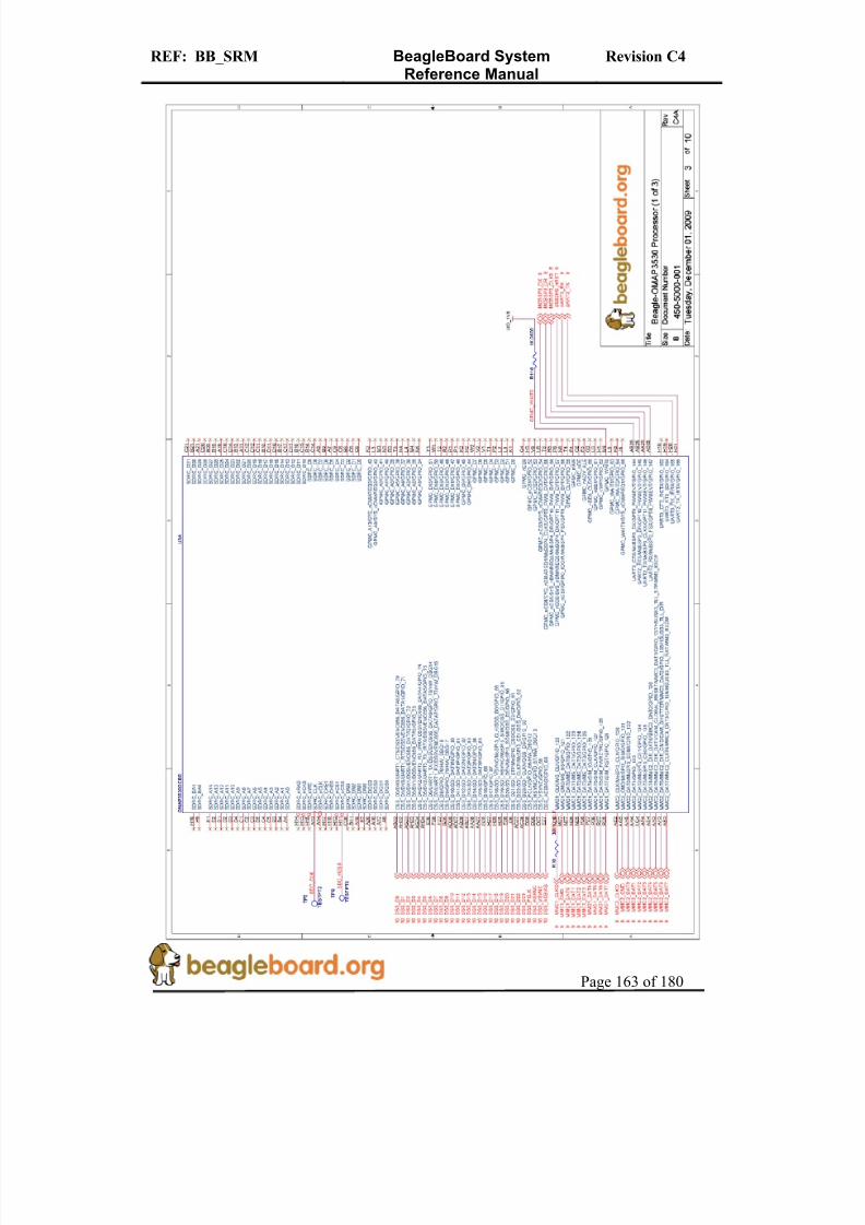
8/2/2019 Beagle Board Manual Rev. C4
http://slidepdf.com/reader/full/beagle-board-manual-rev-c4 163/180
REF: BB_SRM BeagleBoard SystemReference Manual
Revision C4
Page 163 of 180

8/2/2019 Beagle Board Manual Rev. C4
http://slidepdf.com/reader/full/beagle-board-manual-rev-c4 164/180
REF: BB_SRM BeagleBoard SystemReference Manual
Revision C4
Page 164 of 180

8/2/2019 Beagle Board Manual Rev. C4
http://slidepdf.com/reader/full/beagle-board-manual-rev-c4 165/180
REF: BB_SRM BeagleBoard SystemReference Manual
Revision C4
Page 165 of 180

8/2/2019 Beagle Board Manual Rev. C4
http://slidepdf.com/reader/full/beagle-board-manual-rev-c4 166/180
REF: BB_SRM BeagleBoard SystemReference Manual
Revision C4
Page 166 of 180

8/2/2019 Beagle Board Manual Rev. C4
http://slidepdf.com/reader/full/beagle-board-manual-rev-c4 167/180
REF: BB_SRM BeagleBoard SystemReference Manual
Revision C4
Page 167 of 180
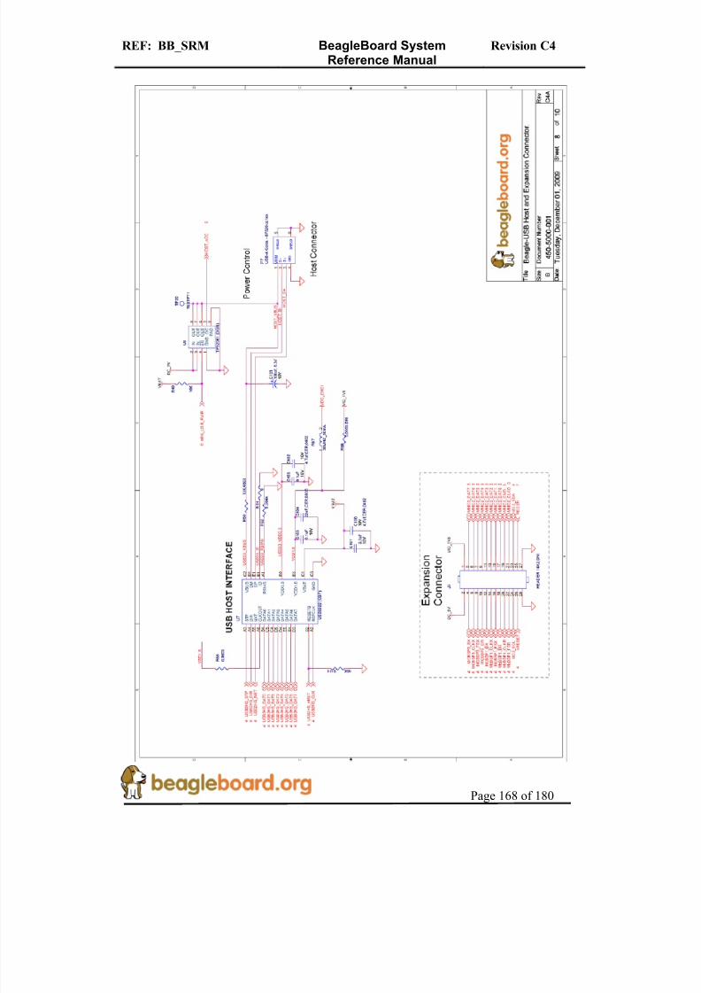
8/2/2019 Beagle Board Manual Rev. C4
http://slidepdf.com/reader/full/beagle-board-manual-rev-c4 168/180
REF: BB_SRM BeagleBoard SystemReference Manual
Revision C4
Page 168 of 180
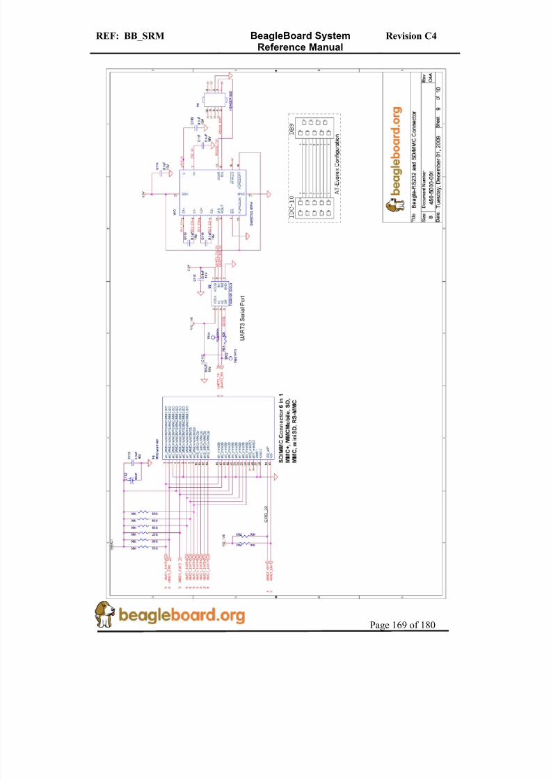
8/2/2019 Beagle Board Manual Rev. C4
http://slidepdf.com/reader/full/beagle-board-manual-rev-c4 169/180
REF: BB_SRM BeagleBoard SystemReference Manual
Revision C4
Page 169 of 180
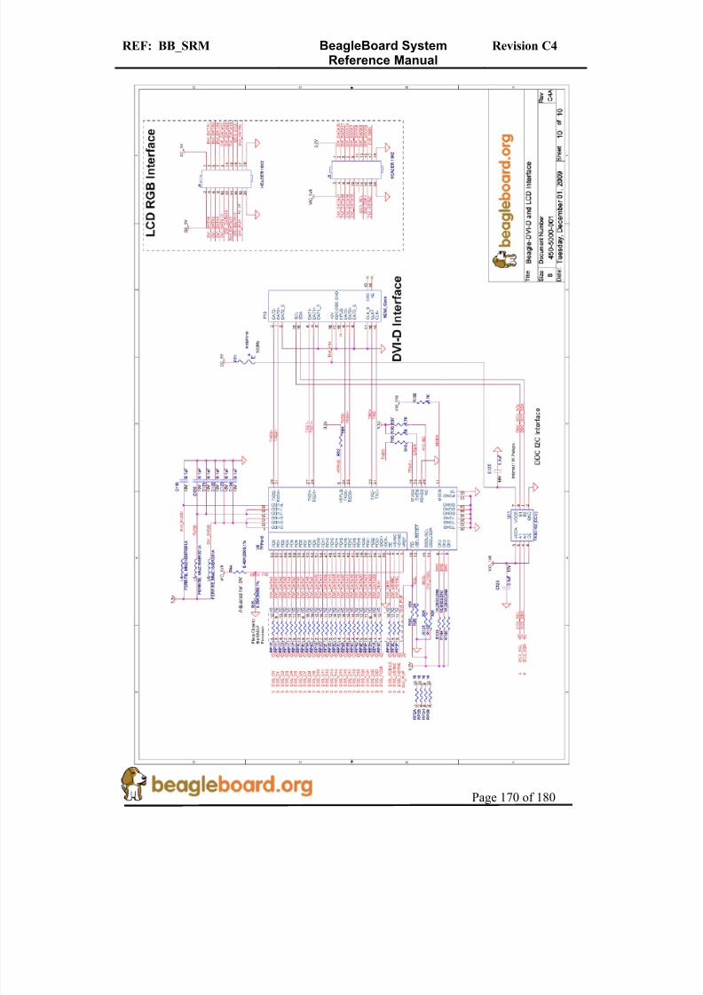
8/2/2019 Beagle Board Manual Rev. C4
http://slidepdf.com/reader/full/beagle-board-manual-rev-c4 170/180
REF: BB_SRM BeagleBoard SystemReference Manual
Revision C4
Page 170 of 180
8/2/2019 Beagle Board Manual Rev. C4
http://slidepdf.com/reader/full/beagle-board-manual-rev-c4 171/180
REF: BB_SRM BeagleBoard SystemReference Manual
Revision C4
Page 171 of 180
17.0 Bills of Material
The Bill of Material for the Beagle Board is provided at BeagleBoard.org at the followinglocation:
http://beagleboard.org/hardware/design
These design materials are *NOT SUPPORTED* and DO NOT constitute a reference
design. Only “community” support is allowed via resources at BeagleBoard.org/discuss.THERE IS NO WARRANTY FOR THE DESIGN MATERIALS, TO THE EXTENT
PERMITTED BY APPLICABLE LAW. EXCEPT WHEN OTHERWISE STATED IN
WRITING THE COPYRIGHT HOLDERS AND/OR OTHER PARTIES PROVIDE THE DESIGN MATERIALS “AS IS” WITHOUT WARRANTY OF ANY KIND, EITHER EXPRESSED OR IMPLIED, INCLUDING, BUT NOT LIMITED TO, THE IMPLIED
WARRANTIES OF MERCHANTABILITY AND FITNESS FOR A PARTICULAR
PURPOSE. THE ENTIRE RISK AS TO THE QUALITY AND PERFORMANCE OF THE DESIGN MATERIALS IS WITH YOU. SHOULD THE DESIGN MATERIALS PROVE
DEFECTIVE, YOU ASSUME THE COST OF ALL NECESSARY SERVICING, REPAIR
OR CORRECTION.We mean it; these design materials may be totally unsuitable for any purposes.

8/2/2019 Beagle Board Manual Rev. C4
http://slidepdf.com/reader/full/beagle-board-manual-rev-c4 172/180
REF: BB_SRM BeagleBoard SystemReference Manual
Revision C4
Page 172 of 180
18.0 PCB Information
The following pages contain the PDF PCB layers for the BeagleBoard. Gerber files andAllegro source files are available on BeagleBoard.org at the following address.
http://beagleboard.org/hardware/design
These design materials are *NOT SUPPORTED* and DO NOT constitute a reference
design. Only “community” support is allowed via resources at BeagleBoard.org/discuss.
THERE IS NO WARRANTY FOR THE DESIGN MATERIALS, TO THE EXTENT PERMITTED BY APPLICABLE LAW. EXCEPT WHEN OTHERWISE STATED IN
WRITING THE COPYRIGHT HOLDERS AND/OR OTHER PARTIES PROVIDE THE DESIGN MATERIALS “AS IS” WITHOUT WARRANTY OF ANY KIND, EITHER
EXPRESSED OR IMPLIED, INCLUDING, BUT NOT LIMITED TO, THE IMPLIEDWARRANTIES OF MERCHANTABILITY AND FITNESS FOR A PARTICULAR
PURPOSE. THE ENTIRE RISK AS TO THE QUALITY AND PERFORMANCE OF THE
DESIGN MATERIALS IS WITH YOU. SHOULD THE DESIGN MATERIALS PROVE
DEFECTIVE, YOU ASSUME THE COST OF ALL NECESSARY SERVICING, REPAIROR CORRECTION.
We mean it; these design materials may be totally unsuitable for any purposes.
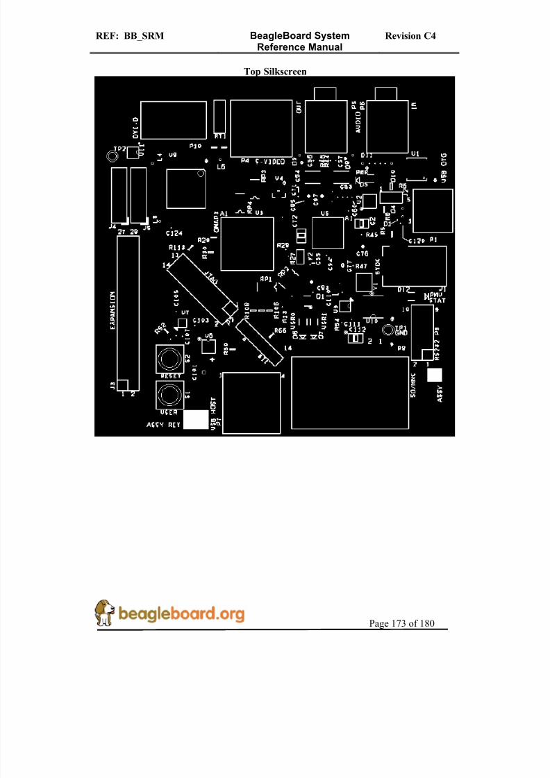
8/2/2019 Beagle Board Manual Rev. C4
http://slidepdf.com/reader/full/beagle-board-manual-rev-c4 173/180
REF: BB_SRM BeagleBoard SystemReference Manual
Revision C4
Page 173 of 180
Top Silkscreen
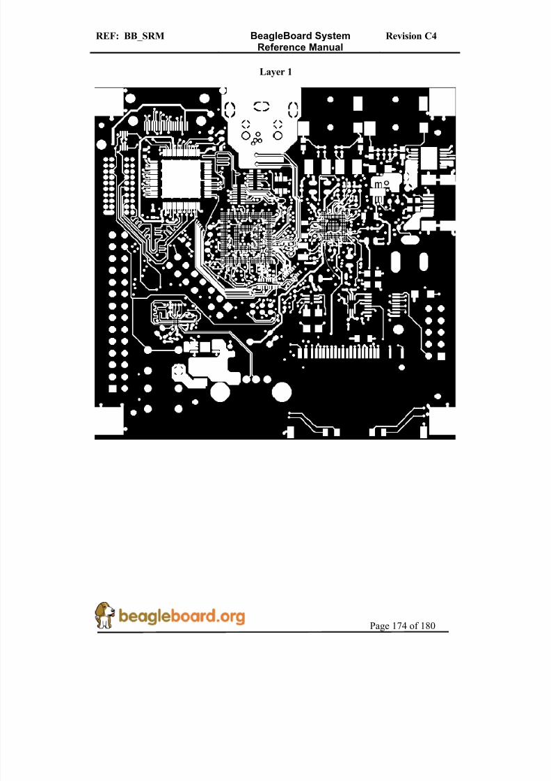
8/2/2019 Beagle Board Manual Rev. C4
http://slidepdf.com/reader/full/beagle-board-manual-rev-c4 174/180
REF: BB_SRM BeagleBoard SystemReference Manual
Revision C4
Page 174 of 180
Layer 1

8/2/2019 Beagle Board Manual Rev. C4
http://slidepdf.com/reader/full/beagle-board-manual-rev-c4 175/180
REF: BB_SRM BeagleBoard SystemReference Manual
Revision C4
Page 175 of 180
Layer 2

8/2/2019 Beagle Board Manual Rev. C4
http://slidepdf.com/reader/full/beagle-board-manual-rev-c4 176/180
REF: BB_SRM BeagleBoard SystemReference Manual
Revision C4
Page 176 of 180
Layer 3

8/2/2019 Beagle Board Manual Rev. C4
http://slidepdf.com/reader/full/beagle-board-manual-rev-c4 177/180
REF: BB_SRM BeagleBoard SystemReference Manual
Revision C4
Page 177 of 180
Layer 4

8/2/2019 Beagle Board Manual Rev. C4
http://slidepdf.com/reader/full/beagle-board-manual-rev-c4 178/180
REF: BB_SRM BeagleBoard SystemReference Manual
Revision C4
Page 178 of 180
Layer 5

8/2/2019 Beagle Board Manual Rev. C4
http://slidepdf.com/reader/full/beagle-board-manual-rev-c4 179/180
REF: BB_SRM BeagleBoard SystemReference Manual
Revision C4
Page 179 of 180
Layer 6
8/2/2019 Beagle Board Manual Rev. C4
http://slidepdf.com/reader/full/beagle-board-manual-rev-c4 180/180
REF: BB_SRM BeagleBoard SystemReference Manual
Revision C4
Bottom Silkscreen