beam instability studies at the aps
TRANSCRIPT

.
Beam Instability Studies at the APS
L. C. Teng Argonne National Laboratory
Introduction
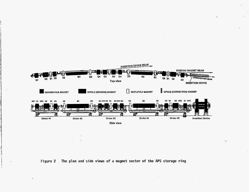
The Argonne Advanced Photon Source, APS (F'ig. l), is a 7-GeV positron storage ring with a circumference of 1104 m. It has a "third generation, DBA or Chasman-Green" lattice composed of 40 sectors each having a -6 m long zero- dispersion straight-section (F'ig. 2) for accommodating insertion devices (wigglers, undulators, etc.). Neighboring straight-sections are connected by a 360'/40 = 9" double-bend-achromatic bending section designed to produce the smallest emittance (8 nm-rad) attainable with reasonable component parameter values and dynamic apertures. Thus, it is a very strongly focusing lattice with v, = 35.22 and vy = 14.30.
The storage ring is injected by a full-energy injector (see Fig. 1) which starts with a 2OO-MeV, 1.5-A electron linac. The electrons strike a target, and the positrons generated are accelerated to 450 MeV in a second linac. Accelerated positron pulses are accumulated in a 450 MeV d.c. Positron Accumulator Ring (PAR) and are damped into a dense bunch. This dense and intense positron bunch is then extracted from the PAR, iqjected into a booster synchrotron and accelerated to 7 GeV for full-energy injection into the storage ring.
Ground was broken for the project on June 4, 1990. As of now the whole injector system is complete and being commissioned. The storage ring is more than halfinstalled and aligned. We anticipate that the installation of the storage ring will be completed and be ready t o accept the 7-GeV beam 6om the injector by the end of this year. Commissioning of the storage ring will then commence.
The beam chamber of the storage ring including all rf, vacuum and photon beam components is designed to ensure that a beam current > 100 mA can be stably stored. We expect that the maximum stable beam current could be as high as 300 mA. This paper will give some details of the studies and computations to ensure the stability of such a beam. The discussions will be organized in the following three parts:
A.
B.
C.
Coupled-bunch instability caused by the higher-order modes (HOMs) of the rf cavities.
Single-bunch instability due t o the resistive wall impedance.
Single-bunch instability due to broadband impedances arising 6om beam chamber irregularities.
L. f%TFfEHJTlDN OF THIS DQCUMENT IS UNLIMITED
The submitted manuscript has been authored by a contractor of the U.S. Government under contract No. W-31-104ENG-38. Accordingly, the U. S. Government retains a nonexclusive, royalty-free license to publish or reproduce the published form of this contribution, or allow others to do so, for U. S. Government purposes.
DISCLAIMER
Portions of this document may be illegible in electronic image products. Images are produced from the best available original document.
Another much more bothersome beam instability is that caused by ground vibration. This instability can only be cured by feedback. Its study and resolution have cost a great deal more effort and.have resulted in many interesting and clever innovations. But this problem is outside the scope of this Workshop.
Clouded-Bunch Instability from Cavity HOMs
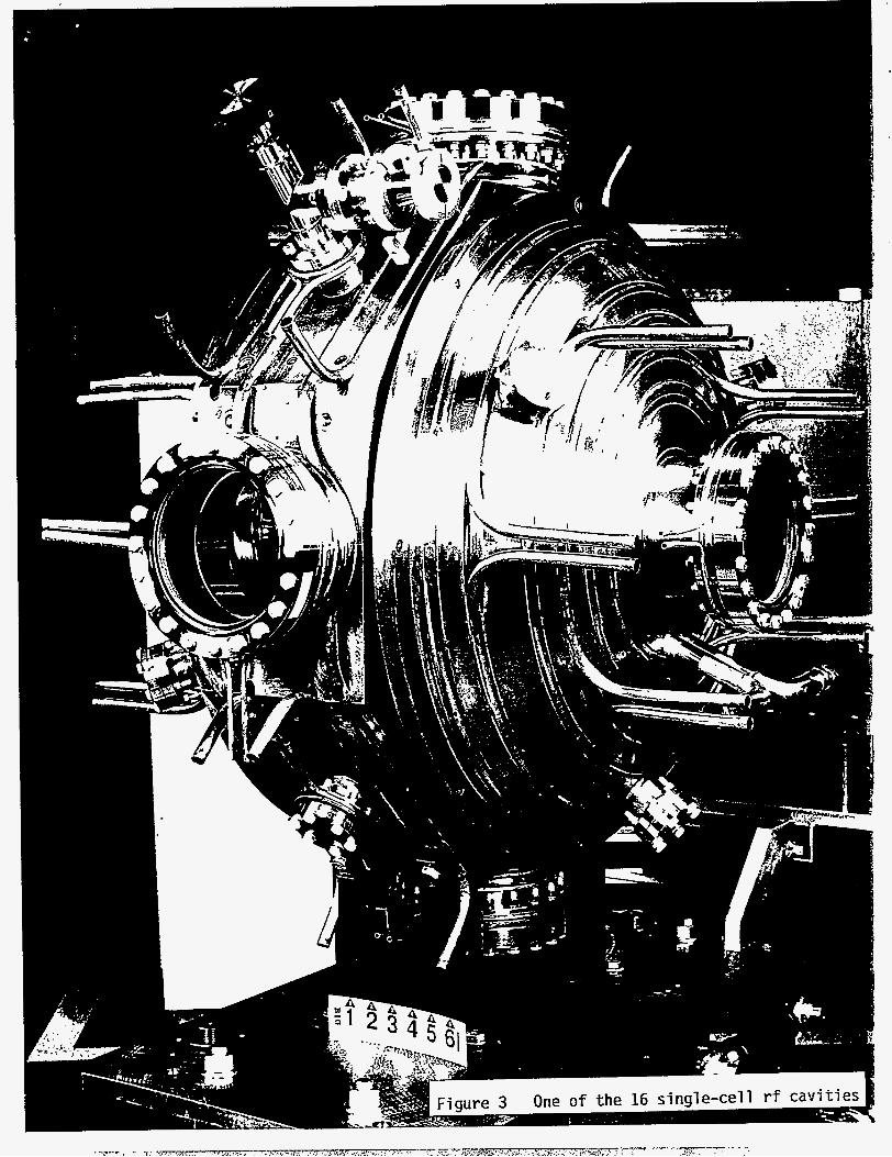
The rf in the APS storage ring is provided by 16 individual cavities each as shown in Fig. 3. The fundamental frequency is 352 MHz corresponding to the 1296th harmonic of the revolution frequency of 271.6 kHz. The HOMs below the cut-off frequency as calculated by the program URMEL are given in Table 1. Due to random construction errors, the frequencies of a particular HOM are slightly different in different cavities. In addition, we deliberately built the cavities each with slightly different length (0.3 mm) so that the mode frequencies are separated as shown in Table 1. This assures that the peak impedance of 16 cavities for an HOM is no greater than that of a single cavity. The fundamental frequencies of the cavities are of course all tuned by tuners to the same design value.
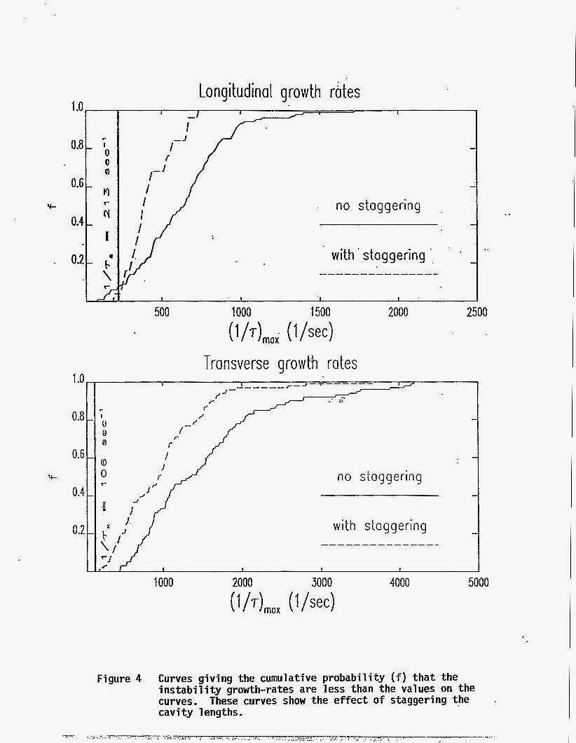
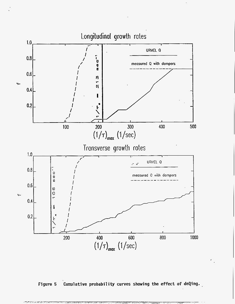
For calculating the growth rates of unstable beam modes due to cavity HOMs it is adequate to assume rigid beam bunches and neglect Landau damping. The calculation of the growth rates of the coupled bunch modes is relatively straightforward even for irregular bunch distributions. We used the treatment by K. Thompson and R. Ruth [l]. Because of the random constructional variations in the mode frequencies and the rather narrow widths of the modes, the computation is by nature a probabilistic one, necessitating the Monte Carlo procedure. Probability of stability is read directly from the cumulative curve which is the integral of the histogram of resonances. The actual range of variation of a mode frequency among the 16 cavities is unknown. We assume a rqnge of +- (revolution frequency) = +- 272 kHz to ensure that some of the HOM frequencies will land on a resonance. The result of the computation is given in Fig. 4. These graphs give the probability that the instability growth rate is less than a given value. The advantage of the stagger- tuning is clearly evident. Also indicated on the graphs are the (negative) synchrotron radiation damping rates. The beam is stable if the instability growth rate is smaller than the negative of the synchrotron radiation damping rates. DeQing of some of the HOMs is clearly necessary. This is accomplished by coupling the specific HOM out with a proper antenna inserted in one of the equatorial ports of the cavity and then attenuating it by a damper. The results of the first round of deQing effort are shown in Fig. 5. We see that the beam is now totally stable longitudinally. Additional effort is needed for the transverse modes.
SingIe-Bunch Instabilitv due to the Resistive Wall Impedance
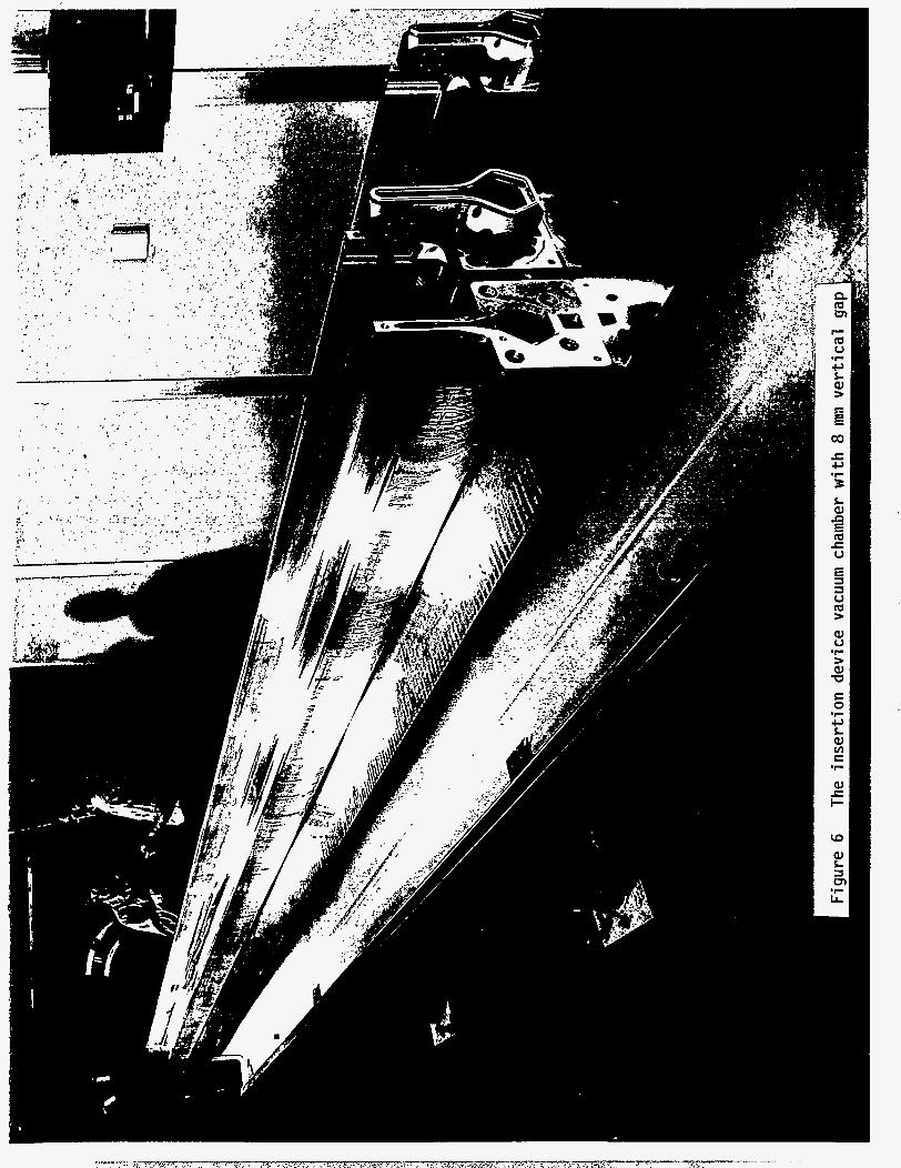
The normal beam chamber of the APS has a vertical height of 4 cm but inside the gap of an undulator in a straight section, the beam chamber vertical height is
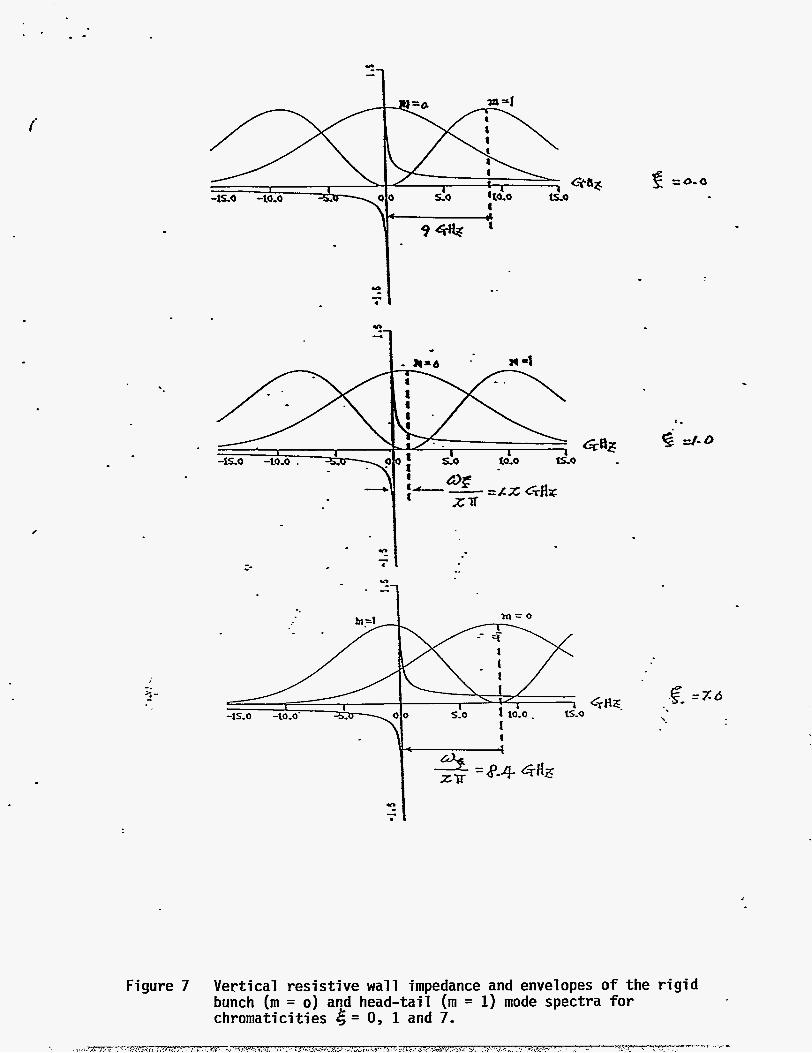
only 8 mm. These insertion device (ID) chambers are extruded from an aluminum alloy, and are each approximately 6 m long (Fig. 6). With a large number (up to 34) of these chamber sections in the ring the vertical resistive wall impedance can be rather large. This impedance is generally proportional to the skin depth of the material of the pipe wall. In the complex form it is plotted in Fig. 7. Numerically for the APS at the revolution frequency of 271 kHz, the magnitude of the transverse impedance is
I ZL I z 35 MWm (34 ID chambers) + 1 MWm (normal chambers).
The general expression for the coherent frequency shift (whose imaginary part gives the instability growth rate) of a bunched beam has been worked out by F. Sacherer [2]. Essentially, the result shows that to the first order, the coherent frequency shift is proportional to the impedance averaged over the power spectam of the instability modes of the beam. The mode frequencies contain harmonics of the revolution frequency, the betatron-oscillation frequency and the synchrotron- oscillation fkequency. In addition, because of the momentum dependence of the betatron tune, the entire spectrum is shifted by the chromaticity frequency a+ = [(chromaticity)/(slppage factor)J(revolution frequency). Although the mode spec- is rather complicated, normally one only has to worry about the m = 0 (rigid bunch) and the m = 1 (head-tail) modes. For the APS with 34 narrow-gap ID chambers and 300-mA beam current the envelopes of the power spectra for the m = 0 and m = 1 modes are also plotted in Fig. 7 for several chromaticity values.
At zero chromaticity the m = 1 mode is unstable. Fig. 7 shows that the chromaticity can significantly modify the coherent frequency shift and that at chromaticity +7 the first lobe of the m = 1 mode-spectrum envelope is shifted near zero frequency so that it becomes stable. This chromaticity value is rather large. However, for the early operation of the storage ring with only 16 ID chambers in place and a beam current of 100 mA stability for m = 0 and m = 1 modes can be obtained by a chromaticity value of only 0.325.
For f d current and ID operation a feedback damper t o damp the m = 1 mode (the m = 0 mode is stable) is also being planned.
Single-Bunch Instabilitv due to Beam Chamber Irregularities
This is a well-trodden topic and our study procedure is fairly traditional. The vacuum chamber of the APS storage ring consists of a beam chamber and a pump chamber connected by a synchrotron radiation escape slot and is extruded from an aluminum alloy (Fig. 5). The beam chamber is roughly elliptical in cross section with major and minor axes of 8 cm and 4 cm, respectively. The synchrotron radiation slot is 1 cm high and extends horizontally from one end of the major axis, having thus, a geometry which sustains only TE modes and hence, presents little coupling to the beam. Its functions are twofold:
a.
b.
No synchrotron radiation strikes the beam chamber wall. Outgassing occurs only in the pump chamber where it is pumped directly by the NEG pumping strips. The slot also acts as an effective isolator so that impedances due to irregularities in the pump chamber are not seen by the beam. It is this feature that we are mainly concerned with here.
Nevertheless, there are many unavoidable irregularities in the beam chamber. The most prominent ones which contributes most to the broadband impedance are:
a. The rfcavities. b. The transition sections joining the regular beam chamber to the larger
rf cavity pipe. There are altogether 2 x 4 of these rf transitions. c. The transition sections joining the regular beam chamber to the much
smaller ID chamber. There can be a maximum of 2 x 34 = 68 of these ID transitions. Beam position monitors--Although each BPM consists of only four button-sized electrodes mounted flush with the beam chamber wall, there are roughly 400 BPMs in the ring.
d.
A number of approximate formulas have been derived for simple, small,
a. b. c.
circular irregularities on a cylindrical pipe, such as: small and shallow circular indentation or protrusion [3] shallow circular tapered transition section [4,51 small holes and narrow longitudinal slots [S, 7, 81
However, to calculate the impedance for a general irregularity one needs to use computer programs such as TBCI, MAFIA, HF'SS, ARGUS, SOS, etc. These programs calculate the wake functions and the impedances in either two dimensions or three dimensions, and in either the time domain or the fkequency domain. As is always true with numerical simulations, all these programs lose precision at very short distances or very high frequencies. Whenever possible, we computed an impedance by as many different procedures as are available and double checked the values against one another. This led to the impedance budget given in Table 2 which shows that the most likely longitudinal and transverse impedances of the storage ring beam chamber are
z, - - 1 Q n
and ZL - 0.15 MWm .
These values are comfortably below the instability threshold of a single-bunch beam current of 5 mA or a 60-bunch beam current of 300 mA.
We constructed a conventional r€-on-wire impedance measuring device. The measurement is, however, not of sufEcient accuracy t o check all the budgeted impedances.
A.
B.
C.
Slrmmm
Coupled-bunch instability from cavity HOMs
The 16 rf cavities are stagger-tuned and the troublesome HOMs are deQed. At this stage, for the full operation of 54 beam bunches at 300 mA the beam is totally stable longitudinally. There is a small probability that the beam may encounter transverse instability by running into some unlucky HOM. Effort is continuing to deQ transverse HOMs to reduce this probability.
Single-bunch instability due to the resistive wall impedance
For the initial operation of only 16 narrow gap insertion-device vacuum chambers and up to 100-mA beam current, a positive chromaticity of 6 = 0.325 will be adequate to stabilize the beam. For the Ml operation of 34 ID chambers and 300-mA beam current, a chromaticity of 6 = 7 is needed. In this case, the use of an electronic feedback damper, is also planned.
Single-bunch instability due to impedance &om beam chamber irregularities
The impedances of various irregularities in the beam chamber are computed using whatever means available. An impedance budget is established using the most trustworthy values. This gives the total impedances
2, - - 1sz n
and ZL. - 0.15 MWm
which are well below the instability thresholds for a single-bunch beam current of 5 mA or a 60-bunch beam current of 300 mA.
Credits
The HOMs of the rf cavities and the instability growth-rate probabilities were computed by Louis Emery. He also proposed the stagger-tuning and computed the deQing required for each mode.
The beam instabilities caused by the resistive wall impedance were investigated in detail by Yong-Chul Chae. He also specified the range of applicability of increasing chromaticity and of feedback damper.
The computation: of the impedance budget in the storage ring was first completed by Weiren Chou and Yuming Jin 191 and was further confirmed and refined by Chae.
References
1.
2.
3.
4.
5.
6.
7.
8.
9.
K. A. Thompson and R. D. Ruth, Proceedings of the 1989 IEEE Particle Accelerator Conference, p. 293 (1989).
F. J. Sacherer, Proceedings 9th International Conference on High Energy Accelerator, Stanford 1974, p. 347; also CERN 77-13, p. 198, (1977).
K. Bane, Proceedings of Impedance and Bunch Instability Workshop, ANLIAPSPTM-5, (1989).
S. S. Kurennoy, CERIN/SL/91-31, (1991).
K. Yokoya, CERIN/SL/90-88, (1990).
S. S. Kurennoy, CERN/SL/91-29, (1991).
R. L. Gluckstern, CERN/SL/92-05 (1992).
Y. C. Chae, Ph.D. Thesis, University of Houston (1993).
W. Chou and Y. Jin, ANL/APS Report LS-115 (1988).

CENTRAL LABlOFFlC
EXPERIMENT
(G E0)CARS-CAT
6/94
Figure 1 Layout o f the Advanced Photon Source
INSERTION DEVICE
QUADRUPOLE MAGNET DIPOLE (BENDING) MAGNET 0 SEXTUPOLE MAGNET DIPOLE (CORRECTION) MAGNET
Hvi ai H V ~ a2 si a3 sz M1 SD Q ~ H V ~ ~ S si asHv4a4
Qlrder a1 Glrder a2 Glrdor a3 Glrdor a4
Side view
Figure 2 The plan and side views of a magnet sector of the APS storage ring
Longitudinal growth rates
I _----- I r - J - f - - - - - -
.- I -
-
-
-
1 1 1
Y-
1 .o
0.8
0.6
'c
0.4
0.2
I / -
no staggering
with. staggering ____-___-------
500 1000 1500 2000 2500 (1/7) rnax . (l/sec)
Transverse growth rates
Figure 4
no staggering
Curves giving the cumulative probability (f) that the instability growth-rates are less than the values on the curves. cavity lengths.
These curves show the effect of staggering the
I 1.0, I c I I
0.8 - 1 0
I URMEL Q I -
a
R
ry
f - measured Q with dampers c1 /
I I I
- v
0.6 -
0.4 I - I I
0.2 - I - t - ' I \
I -
I r r /I 1 1 I I
Figure 5 Cumulative probability curves showing the ef fec t o f deQing.
i
= 4
I t
L
I
'.
-ls.o -lO.O'
U 1
Figure 7 Vertical resistive wall impedance and envelopes of the rigid bunch (m = 0 ) and head-tail (m = 1) mode spectra for chromaticities e = 0, 1 and 7.
-c .. . -. -. . \ , , s . 7 z - T x . - - T , 7 s , ~ m . , I,,:. G , r n % , . w ~ . , ' . . ' ~ ~ ~ ~ * . . ~ , , ~ , . . ' , ~ ~ ~ ~ ' ; ~ ..:. ,:..:-.;.,:. -.. -:L9..J.->,' , . - - ' .'-<,, . < " . . .
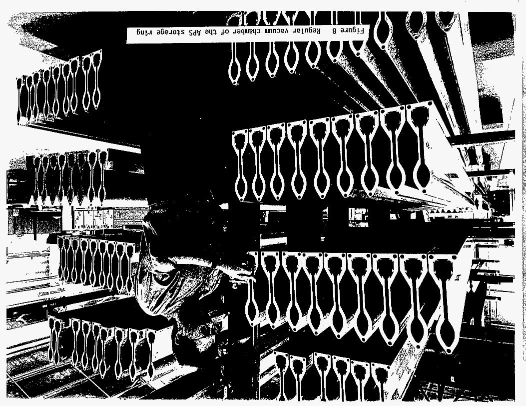
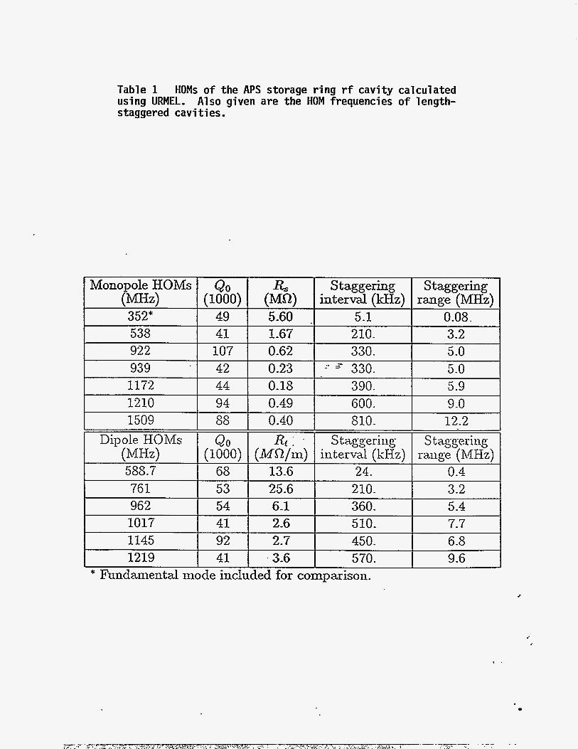
Table 1 HOMs of the APS storage ring rf cavity calculated using URMEL. Also given are the HOM frequencies o f length- staggered cavities.
RS (MQ) 5-60 . 1-67 0-62 0-23
(1000) Staggering Staggering
interval (kHz) range (MHz) 5.1 0.08. 210. 3-2 330. 5.0
5.0 I- z 3-30. 107
0-18 0-49 5 1509
Dipole HOMs Q O 588.7 68 76 1 53
(MHz) (1000)
390. 5 -9 600. 9.0
962 54 1017 41
6-1 2-6
360. 5-4 510. 7.7
2.7 .3-6
0-40 810. 12.2
25.6 210 3.2
450. 6.8 570. 9-6
* Fundamental xiiocle included for comparison.
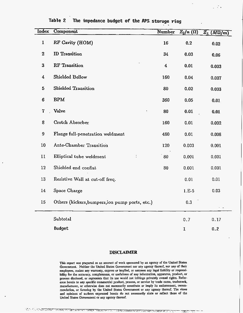
Table 2 The impedance budget of the APS. storage ring . -
Index Component NUxhx q / n (a) 2, (MQ/rn)
RF Cavity (HOM)
ID Transition
RF Transition
Shielded Bellow
Shielded Transition
6 BPM
7 . Valve
8
9
10
11
12
13
14
15
Crotch Absorber
Flange full-penetration weldment
Ante-Chamber Transition
EIIiptical tube weldment
Shielded end conflat
Resistive Wall at cut-off freq-
Space Charge
Others (kickers,bumpers,ion pump ports, etc.)
16
34
4
160
80
360
80
160
480
120
80
SO
0.2
0.03
0.01
0.04
0.02
0.05
0.01
0.01
0.01
0.003
0.00 1
0.001
0.01
1.E-5
0.02
0.06
0.003
0.007
0.003
0.01
0.01
0.002
0.008
0-001
0.001
0.001
0.01
0.03
0.3 - - -
S ubto t a1 0.7
Budget 1
0.17
0.2
DISCLAIMER
This report was prepared as an account of work sponsored by an agency of the United States Government. Neither the United States Government nor any agency thereof, nor any of their employees, makes any warranty, express or implied, or assumes any legal liability or responsi- bility for the accuracy, completeness, or usefulness of any information, apparatus, product, or process disclosed, or represents that its use would not infringe privately owned rights. Refer- ence herein to any specific commercial product, process, or service by trade name, trademark, manufacturer, or otherwise does not necessarily constitute or imply its endorsement, recom- mendation, or favoring by the United States Government or any agency thereof. The views and opinions of authors expressed herein do not necessarily state or reflect those of the United States Government or any agency thereof.