beam loading compensation for optimal bunch …
TRANSCRIPT

BEAM LOADING COMPENSATION FOR OPTIMAL BUNCHLENGTHENING WITH HARMONIC CAVITIES
Naoto Yamamoto⇤, Takeshi Takahashi, Shogo Sakanaka KEK, Tsukuba, Japan
AbstractEmittance growth and short beam lifetime due to intra-
beam scattering in extremely low emittance storage ringscan be mitigated if harmonic rf cavities are used for the pur-pose of lengthening the longitudinal bunch size. The “flatpotential condition” can be achieved with harmonic cavities,lengthening the bunch by a factor of ⇠ 5. However, the per-formance is limited by the transient beam-loading e�ect inthe rf cavities, which is induced by gaps in the ring fill pat-tern. As a counter-measure of this e�ect, we have proposedthe active compensation techniques by using a single kickercavity having a bandwidth of several times the revolutionfrequency. The transient e�ect can be compensated whenthe kicker cavity voltage is determined to suppress bunchphase shifts along the train.
INTRODUCTIONExtremely low emittance storage rings, which aim at
achieving the beam emittances of < 100 pm-rad, are be-ing actively designed as future ring-based synchrotron lightsources. In such rings, emittance growth and short beamlifetime due to intrabeam scattering are of serious concern.To mitigate such adverse e�ects, a harmonic radio-frequency(rf) system [1] is used to lengthen the beam bunches, so thatthe particle density at the core of the bunch can be reduced.
Harmonic rf systems have been successfully operated tolengthen beam bunches in several light sources [2–9]. How-ever, in some of them, the bunch-lengthening performancewas limited due to the transient beam-loading (TBL) e�ectwhen the large bunch gaps are introduced [3–5]. It was re-ported [10] that the reduction of a total R/Q of rf cavities isessential to alleviate such transient e�ects.
The voltage fluctuations due to the TBL e�ect can bereduced when rf cavities having a small total R/Q are em-ployed as shown in Fig. 7 in reference [11]. When the re-maining variation of cavity voltages is kept smaller thanseveral tens kV, we can further improve the bunch lengthen-ing performance using a single kicker cavity within technicalfeasibility. In reference [11], we proposed two measures foractive compensation techniques: compensation on the fun-damental and harmonic cavities, and compensation using aseparate kicker cavity.
As a next step of this work, feasiblity studies of the ac-tive compensation techniques using a separate kicker cavitywere made. In this paper, we present numerical calculationresults after the details of the compensation techniques aredescribed.
Table 1: Main parameters of the KEK-LS without harmonicrf systems, including insertion device losses.
Parameter Value
Nominal beam energy 3.0 GeVStored beam current 500 mARF frequency (fundamental) 500.07 MHzHarmonic number 952Revolution frequency 525 kHzUnperturbed synchrotron frequency 2.65 kHzSynchrotron radiation loss per turn 851 keVMain rf voltage 2.5 MVNatural relative energy spread (rms) 7.3 ⇥ 10�4
Momentum compaction factor 2.2 ⇥ 10�4
Longitudinal radiation damping time 7.0 msNatural bunch length (rms) 9.5 ps
Table 2: Parameters of the KEK-LS rf systems used in cal-culations at the beam current of 500 mA. For the fundamen-tal and third harmonic cavities, the PF-type cavity and theTM020 cavity were assumed, respectively. The synchronousphases are shown in the cosine definition.
Parameter Fund. rf Harmonic rf(3rd)
Rf voltage 2.5 MV 777 kVSynchronous phase 1.178 rad -1.708 radTuning angle -0.962 rad 1.433 radTotal R/Q (R = V2
c/Pc) 875 ⌦ 386 ⌦
Total shunt impedance 35 M⌦ 14.48 M⌦Cavity coupling 3.5 0.27Cavity detuning amount -40.3 kHz 185 kHz
KEK-LS STORAGE RINGAs an example of the extremely low emittance storage
rings for feasibility study of the TBL compensation, weassumed the KEK light source (KEK-LS) [12]. Table 1shows the main parameters of the KEK-LS. The KEK-LShas a design based on the hybrid multi-bend achromaticlattice. Although the natural emittance of 0.13 nm-rad isexpected with zero beam current, the emittance a�ected bythe intra-beam scattering is estimated to be 0.31 nm-rad atthe nominal beam current of 500 mA. Then we have plannedto introduce the harmonic cavities to mitigate the impact ofthe intra-beam scattering.
The assumed parameters for the fundamental and har-monic rf system are summarized in Table 2. The existingPhoton Factory (PF) type cavities [13] are assumed for thefundamental cavity. A typical total RF voltage of 2.5 MV is
Proceedings of the ICFA mini-Workshop, MCBI 2019, Zermatt, Switzerland
96

Low Level
RF system
Dummy load
RF Amp.
Master
Oscillator
Fundamentalcavity
Harmoniccavity
(Adaptive) feedforward modulated signal
Beam monitor
Kicker Cavity
Figure 1: A Schematic of active compensation for transient beam loading e�ect.
produced by five cavities, where each cavity has an unloadedQ of 40,000 and R/Q of 175 ⌦.
Concerning harmonic rf cavities for the KEK-LS, thecandidate is a normal conducting TM020 cavity having theresonant frequency of 1.5 GHz, which is the third harmonicof the fundamental frequency, since lower R/Q and higherunloaded Q, as compared to the conventional TM010 cavityare expected [14, 15]. In this investigation, R/Q of 77.2 ⌦and unloaded Q of 37,500 are expected for one 1.5 GHz-TM020 cavity. At nominal stored current of 500 mA, the “flatpotential condition”, which means that the voltage slope andthe first derivative of the slope become zero, is satisfied withthe cavity coupling of 0.27 and detuning amount of 185 kHz.At these conditions, the input power of the harmonic cavitiesideally becomes zero, that is to say, passive cavity operation.
ACTIVE COMPENSATION SYSTEMThe schematic of an active compensation system using a
separate kicker cavity is shown in Fig. 1. We have consideredto use a kicker cavity having the wide bandwidth, a solid stateamplifier and a feedforward low level rf (LLRF) control.
For the bandwidth of the feedforward signal, we considerthe frequency range of about several megahertz, coveringmultiples of the repetition frequency of the fill pattern fortypical synchrotron sources.
Kicker cavityA single kicker cavity is the key equipment of this system.
The cavity parameters shown in Table 3 are assumed for thefeasibility studies. The summarized parameters are basedon that of the PF-type 500-MHz cavity [13]. The cavitycoupling is changed to realize the adequate cavity bandwidth.The 3dB full bandwidth of 5.0 MHz, which is given by(1 + �)/Q0 ⇥ fr , is expected if the cavity coupling (�) isset to 199 for a cavity having the resonant frequency ( fr ) of500 MHz and unloaded Q (Q0) of 40,000, respectively.
Solid state amplifierIn order to compensate the transient voltages, the band-
widths of rf generators should be wider than the bandwidths
Table 3: Assumed parameters for a single cavity of the com-pensation system.
Parameter Value
Resonant frequency 500.07 MHzR/Q 175 ⌦Unloaded Q 40,000Cavity number 1Cavity coupling coe�cient 199-3dB full bandwidth 5.0 MHz
of feedforward signal. Then as a high power rf amplifier forthe active compensation system, a solid state amplifier ispreferred option due to the intrinsic advantage of the widerbandwidth as compared to a klystron-based amplifier. Asa result of feasibility test, we obtained a 1-dB full band-width of about 10 MHz with our prototype 1-kW, 500-MHzsolid-state amplifier.
Adaptive feedforward LLRF systemThe LLRF system should provide an rf signal including a
fast feedforward pattern to compensate the transients whilestabilizing both amplitude and phase of rf voltage on aver-age using some feedback loops. We believe that both thefeedforward and the feedback should be realized compatiblyif they have much di�erent response time.
At this moment, we have not determined the practicaldesign of the feedforward LLRF system. A possible solutionis reading both fill pattern and beam current in the system,calculating necessary feedforward pattern, and outputtingthe desired rf signal from the LLRF system.
COMPENSATION USING SINGLEKICKER CAVITY
In this section, we explain how to obtain the feedforwardsignal of a single kicker cavity in case that the voltage fluctua-tions along the bunch train for the fundamental and harmoniccavities are given. Then, the calculation results obtained in
CERN Yellow Reports: Conference Proceedings, CERN-2020-009
97
the KEK-LS case are shown as an example of the transientcompensation.
The voltage fluctuations are anticipated numerically byusing analytical [11] or tracking [16] tools if the operationparameters of the ring, including the bunch fill pattern , areknown. For practical cases, it is considered that we canmeasure the fluctuations through rf cavity pickups experi-mentally.
Feedforward signalOnce cavity voltage fluctuations are caused by TBL e�ect,
synchronous phases of bunches are varied according to thelocation in the bunch train. The amount of the phase shift islarger in the bunch lengthening operation mode comparedto the other operation modes because of the nonlinearityof the harmonic rf voltage. The feedforward signal for akicker cavity should be determined to minimizing thesephase shifts.
When in the complex plane, voltages of both the funda-mental and n-th harmonic cavity are represented by Vc,1(m)
and Vc,n(m) as functions of the bucket number m, the kickercavity voltage Vc,k(m) should satisfied the following require-ment for canceling the bunch phase shift,
Re[Vc,k(m)] = �(Re[Vc,1(m) + Vc,n(m)] � U0/e), (1)
where U0 is the radiation loss per turn, e is the electroncharge and Re[Vc] is the accelerating voltage seen by thebeam. If the resonant frequency of the kicker cavity is exactlythe same or integer multiple of the ring rf frequency, theamplitude of the kicker cavity voltage is represented by
|Vc,k(m)| = Re[Vc,k(m)]/cos �s,k, (2)
where �s,k is the cavity synchronous phase of the kickercavity in the cosine definition.
Then using the beam induced voltage in the kicker cavityVb,k(m), we obtain the required generator voltage
Vg,k(m) = Vc,k(m) � Vb,k(m). (3)
The generator current can be calculated using the kickercavity response given in Eq. (25) of Ref [11]. Consequently,we deduce the input signal for the LLRF system after someband-limiting treatments to keep the peak generator powertechnically feasible.
Analytical simulation for KEK-LS caseIn a standard operation of the KEK-LS ring, all rf buckets
will be equally filled with electrons, except for the bunchgaps. To avoid ion trapping, we introduce several bunchgaps symmetrically in the ring. The number and duration ofthe gaps are tentatively 2 and 60 ns, respectively.
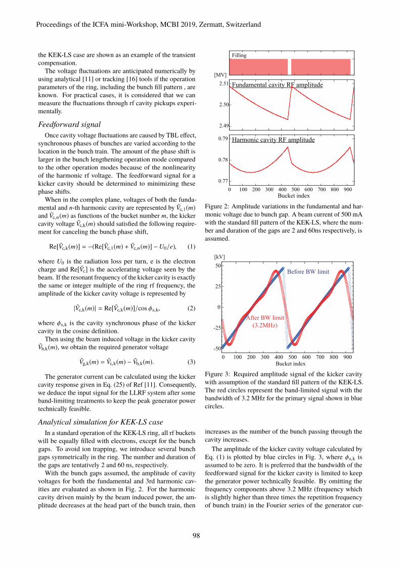
With the bunch gaps assumed, the amplitude of cavityvoltages for both the fundamental and 3rd harmonic cav-ities are evaluated as shown in Fig. 2. For the harmoniccavity driven mainly by the beam induced power, the am-plitude decreases at the head part of the bunch train, then
Filling
2.49
2.50
2.51
[MV]
Fundamental cavity RF amplitude
0.77
0.78
0.79
0 100 200 300 400 500 600 700 800 900Bucket index
Harmonic cavity RF amplitude
Figure 2: Amplitude variations in the fundamental and har-monic voltage due to bunch gap. A beam current of 500 mAwith the standard fill pattern of the KEK-LS, where the num-ber and duration of the gaps are 2 and 60ns respectively, isassumed.
-50
-25
0
25
50
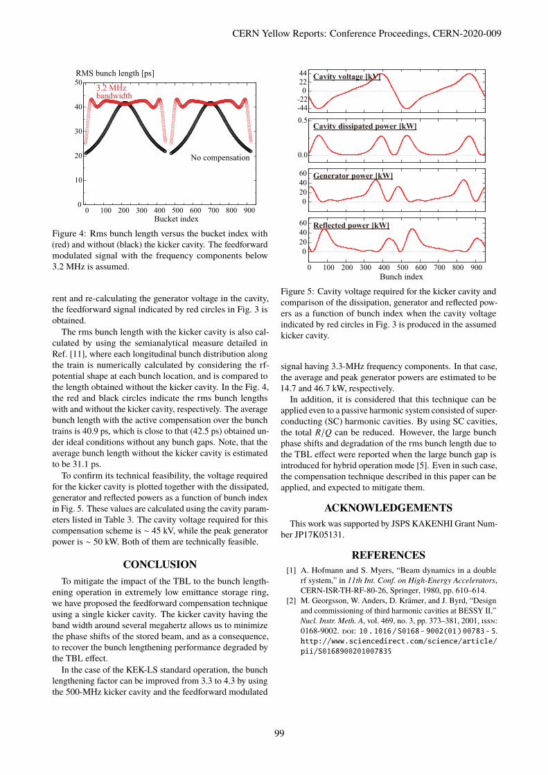
0 100 200 300 400 500 600 700 800 900Bucket index
Before BW limit
After BW limit(3.2MHz)
[kV]
Figure 3: Required amplitude signal of the kicker cavitywith assumption of the standard fill pattern of the KEK-LS.The red circles represent the band-limited signal with thebandwidth of 3.2 MHz for the primary signal shown in bluecircles.
increases as the number of the bunch passing through thecavity increases.
The amplitude of the kicker cavity voltage calculated byEq. (1) is plotted by blue circles in Fig. 3, where �s,k isassumed to be zero. It is preferred that the bandwidth of thefeedforward signal for the kicker cavity is limited to keepthe generator power technically feasible. By omitting thefrequency components above 3.2 MHz (frequency whichis slightly higher than three times the repetition frequencyof bunch train) in the Fourier series of the generator cur-
Proceedings of the ICFA mini-Workshop, MCBI 2019, Zermatt, Switzerland
98
0
10
20
30
40
50
0 100 200 300 400 500 600 700 800 900
RMS bunch length [ps]
Bucket index
No compensation
3.2 MHzbandwidth
Figure 4: Rms bunch length versus the bucket index with(red) and without (black) the kicker cavity. The feedforwardmodulated signal with the frequency components below3.2 MHz is assumed.
rent and re-calculating the generator voltage in the cavity,the feedforward signal indicated by red circles in Fig. 3 isobtained.
The rms bunch length with the kicker cavity is also cal-culated by using the semianalytical measure detailed inRef. [11], where each longitudinal bunch distribution alongthe train is numerically calculated by considering the rf-potential shape at each bunch location, and is compared tothe length obtained without the kicker cavity. In the Fig. 4,the red and black circles indicate the rms bunch lengthswith and without the kicker cavity, respectively. The averagebunch length with the active compensation over the bunchtrains is 40.9 ps, which is close to that (42.5 ps) obtained un-der ideal conditions without any bunch gaps. Note, that theaverage bunch length without the kicker cavity is estimatedto be 31.1 ps.
To confirm its technical feasibility, the voltage requiredfor the kicker cavity is plotted together with the dissipated,generator and reflected powers as a function of bunch indexin Fig. 5. These values are calculated using the cavity param-eters listed in Table 3. The cavity voltage required for thiscompensation scheme is ⇠ 45 kV, while the peak generatorpower is ⇠ 50 kW. Both of them are technically feasible.
CONCLUSIONTo mitigate the impact of the TBL to the bunch length-
ening operation in extremely low emittance storage ring,we have proposed the feedforward compensation techniqueusing a single kicker cavity. The kicker cavity having theband width around several megahertz allows us to minimizethe phase shifts of the stored beam, and as a consequence,to recover the bunch lengthening performance degraded bythe TBL e�ect.
In the case of the KEK-LS standard operation, the bunchlengthening factor can be improved from 3.3 to 4.3 by usingthe 500-MHz kicker cavity and the feedforward modulated
-44
-22
0
22
44
0.0
0.5Cavity dissipated power [kW]
0
20
40
60 Generator power [kW]
0
20
40
60
0 100 200 300 400 500 600 700 800 900
Bunch index
Reflected power [kW]
Cavity voltage [kV]
Figure 5: Cavity voltage required for the kicker cavity andcomparison of the dissipation, generator and reflected pow-ers as a function of bunch index when the cavity voltageindicated by red circles in Fig. 3 is produced in the assumedkicker cavity.
signal having 3.3-MHz frequency components. In that case,the average and peak generator powers are estimated to be14.7 and 46.7 kW, respectively.
In addition, it is considered that this technique can beapplied even to a passive harmonic system consisted of super-conducting (SC) harmonic cavities. By using SC cavities,the total R/Q can be reduced. However, the large bunchphase shifts and degradation of the rms bunch length due tothe TBL e�ect were reported when the large bunch gap isintroduced for hybrid operation mode [5]. Even in such case,the compensation technique described in this paper can beapplied, and expected to mitigate them.
ACKNOWLEDGEMENTSThis work was supported by JSPS KAKENHI Grant Num-
ber JP17K05131.
REFERENCES[1] A. Hofmann and S. Myers, “Beam dynamics in a double
rf system,” in 11th Int. Conf. on High-Energy Accelerators,CERN-ISR-TH-RF-80-26, Springer, 1980, pp. 610–614.
[2] M. Georgsson, W. Anders, D. Krämer, and J. Byrd, “Designand commissioning of third harmonic cavities at BESSY II,”Nucl. Instr. Meth. A, vol. 469, no. 3, pp. 373–381, 2001, ����:0168-9002. ���: 1�.1�16/S�168- 9��2(�1)��783- 5.http://www.sciencedirect.com/science/article/pii/S�1689��2�1��7835
CERN Yellow Reports: Conference Proceedings, CERN-2020-009
99

[3] J. Byrd, S. Santis, M. Georgsson, G. Stover, J. Fox, andD. Teytelman, “Commissioning of a higher harmonic RFsystem for the advanced light source,” Nucl. Instr. Meth.A, vol. 455, no. 2, pp. 271–282, 2000, ����: 0168-9002.���: 1� . 1�16 / S�168 - 9��2(�� ) ��5�4 - �. http : / /www . sciencedirect . com / science / article / pii /S�1689��2����5�4�
[4] W. Anders and P. Kuske, “HOM damped NC passive har-monic cavities at BESSY,” in Proc. of the 2003 ParticleAccelerator Conf., paper TPAB004, vol. 2, 2003, pp. 1186–1188.
[5] M. Pedrozzi et al., “SLS operational performance with thirdharmonic superconducting system,” in Proc. of 11th SRFworkshop, paper MOP25, 2003, pp. 91–94.
[6] N. Milas, L. Stingelin, et al., “Impact of filling patterns onbunch length and lifetime at the sls,” IPAC10, Kyoto, Japan,2010.
[7] P. Bosland et al., “Third harmonic superconducting passivecavities in ELETTRA and SLS,” in Proc. of 11th SRF work-shop, paper TUO06, 2003, pp. 239–243.
[8] G. Penco and M. Svandrlik, “Experimental studies on tran-sient beam loading e�ects in the presence of a superconduct-ing third harmonic cavity,” Phys. Rev. ST Accel. Beams, vol. 9,p. 044 401, 4 Apr. 2006. ���: 1� . 11�3/ PhysRevSTAB .9.�444�1. http://link.aps.org/doi/1�.11�3/PhysRevSTAB.9.�444�1
[9] P. F. Tavares et al., “Commissioning and first-year operationalresults of the MAX IV 3 GeV ring,” Journal of SynchrotronRadiation, vol. 25, no. 5, pp. 1291–1316, Aug. 2018. ���:1�.11�7/s16��577518��8111.
[10] J. M. Byrd, S. De Santis, J. Jacob, and V. Serriere, “Tran-sient beam loading e�ects in harmonic rf systems for lightsources,” Phys. Rev. ST Accel. Beams, vol. 5, p. 092 001,9 Sep. 2002. ���: 1�.11�3/PhysRevSTAB.5.�92��1.http://link.aps.org/doi/1�.11�3/PhysRevSTAB.5.�92��1
[11] N. Yamamoto, T. Takahashi, and S. Sakanaka, “Reduction
and compensation of the transient beam loading e�ect in adouble rf system of synchrotron light sources,” Phys. Rev.Accel. Beams, vol. 21, 1 Jan. 2018, 012001. ���: 1�.11�3/PhysRevAccelBeams.21.�12��1. https://link.aps.org/doi/1�.11�3/PhysRevAccelBeams.21.�12��1
[12] Y. Honda et al., “Resonant coherent di�raction radiation sys-tem at ERL test accelerator in KEK,” in Proceedings of the8th Internatinal Particle Accelerator Conf., IPAC’17, Copen-hagen, Denmark, MOPVA018, JACOW, Geneva, Switzer-land, 2017, pp. 887–889.
[13] M. Izawa et al., “Installation of new damped cavities at thephoton factory storage ring,” JSR, vol. 5, no. 3, pp. 369–371,May 1998. ���: 1�.11�7/S�9�9�49597�15�7�. http://dx.doi.org/1�.11�7/S�9�9�49597�15�7�
[14] H. Ego, J. Watanabe, S. Kimura, and K. Sato, “Design ofa HOM-damped rf cavity for the SPring-8-II storage ring,”in Proc. 11th Annual Meeting of Particle Accelerator So-ciety of Japan, paper MOOL14 in Japanese, PASJ, Tokyo,2014, 2014, pp. 237–241. http://www.pasj.jp/web_publish/pasj2�14/proceedings/PDF/MOOL/MOOL14.pdf
[15] N. Yamamoto, S. Sakanaka, and T. Takahashi, “Simulationstudy of parasitic-mode damping methods for a 1.5-ghztm020-mode harmonic cavity,” en-us, in Proceedings of the9th Internatinal Particle Accelerator Conf., IPAC’18, Van-couver, BC, Canada, vol. IPAC2018, JACoW Publishing,Geneva, Switzerland, 2018, p. 2822. ���: 1�.18429/jacow-ipac2�18-wepml�55.
[16] N. Yamamoto, A. Gamelin, and R. Nagaoka, “Investigationof Longitudinal Beam Dynamics With Harmonic Cavities byUsing the Code Mbtrack,” in Proc. 10th International PartileAccelerator Conference (IPAC’19), Melbourne, Australia, 19-24 May 2019, (Melbourne, Australia), ser. International Par-tile Accelerator Conference, Geneva, Switzerland: JACoWPublishing, Jun. 2019, pp. 178–180, ����: 978-3-95450-208-0. ���: doi:1�.18429/JACoW- IPAC2�19- MOPGW�39.http://jacow.org/ipac2�19/papers/mopgw�39.pdf
Proceedings of the ICFA mini-Workshop, MCBI 2019, Zermatt, Switzerland
100