beam vacuum interactions ii - cern
TRANSCRIPT
Beam vacuum interactions II
Oswald Gröbner
O. Gröbner, CERN-Vauum group (ret.)
Present address: Schmiedgasse 5, 6020 Innsbruck, Austria
E-mail: [email protected]@cern.ch
Vacuum in Accelerators 16-24 May 2006, Platja d’Aro, Spain
O. Gröbner Beam vacuum interactions II 2
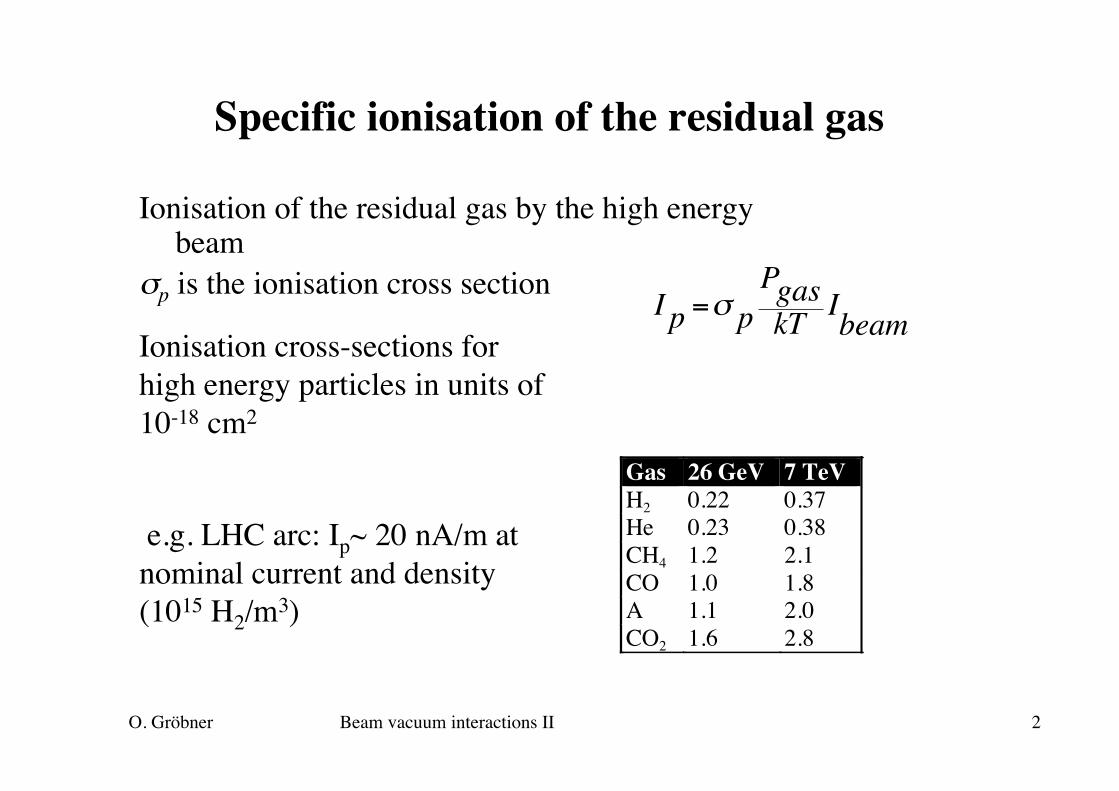
Specific ionisation of the residual gas
Ionisation of the residual gas by the high energybeam
σp is the ionisation cross section
€
I p =σ pPgaskT IbeamIonisation cross-sections for
high energy particles in units of10-18 cm2
Gas 26 GeV 7 TeVH2 0.22 0.37He 0.23 0.38CH4 1.2 2.1CO 1.0 1.8A 1.1 2.0CO2 1.6 2.8
e.g. LHC arc: Ip~ 20 nA/m atnominal current and density(1015 H2/m3)

O. Gröbner Beam vacuum interactions II 3
Power loss by nuclear scattering
Particles lost by nuclear scattering along the arcs of amachine can not be collimated and their losses occuruniformly distributed around the arcs
€
P(w /m)=1cIEτ
=0.93 I(A)E(TeV )τ(h)
LHC design requires a nuclear-scattering life time of ~ 100h
LHC -> 0.1 W/m for two beams at ultimate current requiredgas density equivalent to 1015 H2/m3
Each W at 1.9 K ~ 500 W at RT (Ph.L. lecture)

O. Gröbner Beam vacuum interactions II 4
Space charge potential of the beam
Line density (particles/m), totalcurrent I
Circular, concentric geometry, beamwith uniform charge and radius a .Electric field follows from Gauss law
€
λ =Ieβc
€
ε r( ) =eλ2πε0
ra2
r ≤ a
€
ε r( ) =eλ2πε0
1r
r ≥ a
Integrating the field gives the potentialin the centre of the beam
€
Vb =eλ2πε0
12
+ lnrpa
ISR: I = 20 A, rp = 0.08 m a = 0.01 mElectrons remain trappedin the potential well
O. Gröbner Beam vacuum interactions II 5
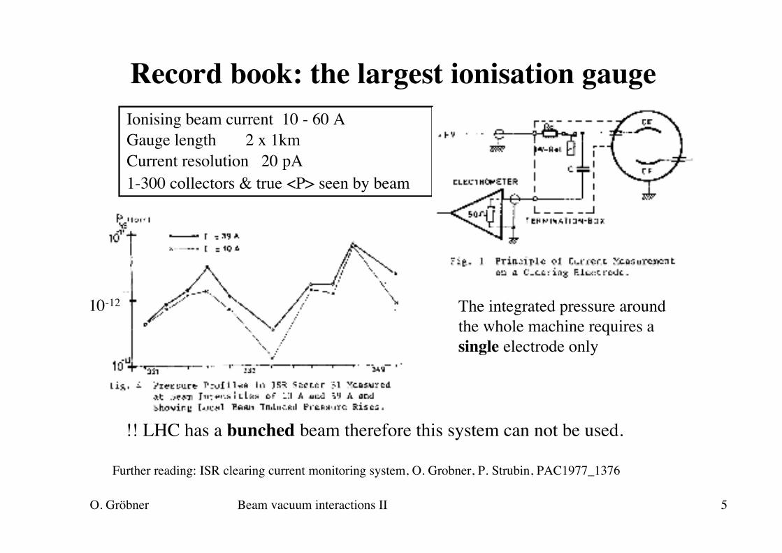
Record book: the largest ionisation gaugeIonising beam current 10 - 60 AGauge length 2 x 1kmCurrent resolution 20 pA1-300 collectors & true <P> seen by beam
Further reading: ISR clearing current monitoring system, O. Grobner, P. Strubin, PAC1977_1376
The integrated pressure aroundthe whole machine requires asingle electrode only
!! LHC has a bunched beam therefore this system can not be used.
10-12

O. Gröbner Beam vacuum interactions II 6
Beam space charge neutralisation
The neutralisation factor is defined asNb is the number of beam particles ni is the neutralising charge, i.e. electrons trapped ina proton beam, or positive ions trapped in an electronor antiproton beam.Production rate (s-1 m-1) depends on gas density
€
η =niNb
≤1
Equilibrium neutralisation
€
ηequ =RpRc
Trapped charges neutralise the beam space charge and cause atune shift and beam instabilities
€
Rp = βcngσ i
The clearing rate Rc depends on the specific mechanism
prop. to pressure!
O. Gröbner Beam vacuum interactions II 7
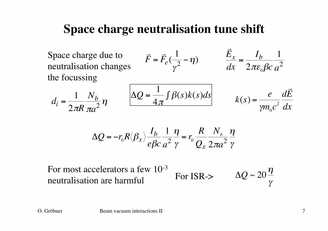
Space charge neutralisation tune shift
Space charge due toneutralisation changesthe focussing
€
k(s) =e
γm0c2
dr E
dx
€
ΔQ =14π
β(s)k(s)ds∫
€
di =12πR
Nbπa2
η
€
ΔQ ~ 20ηγ
For most accelerators a few 10-3
neutralisation are harmful
€
r E xdx
=Ib
2πε0βc1a2
€
r F =
r F e(
1γ2−η)
€
ΔQ = −r0R βxIbeβc
1a2ηγ
= r0RQx
Nb
2πa2ηγ
For ISR->
O. Gröbner Beam vacuum interactions II 8
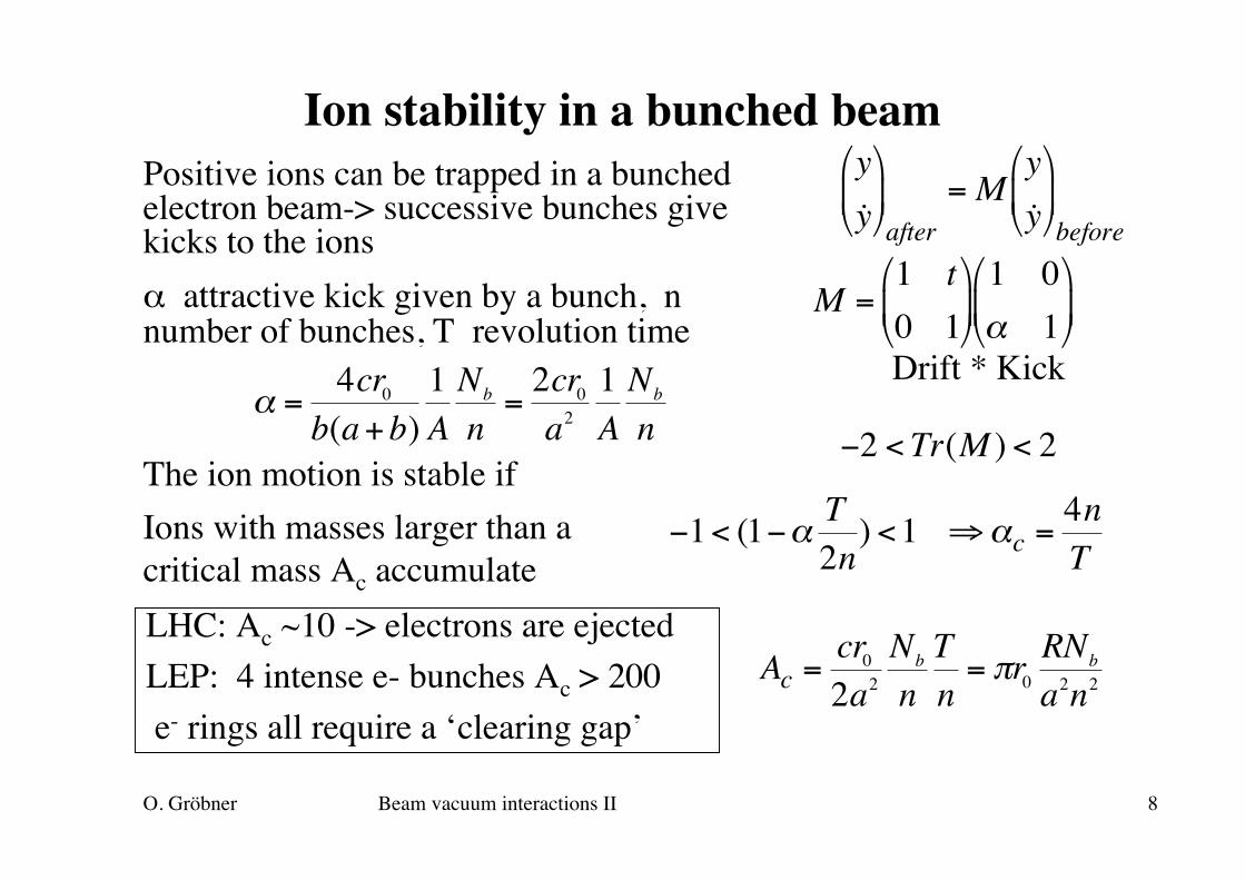
Ion stability in a bunched beamPositive ions can be trapped in a bunchedelectron beam-> successive bunches givekicks to the ionsα attractive kick given by a bunch, nnumber of bunches, T revolution time
€
α =4cr0
b(a+b)1ANb
n=2cr0a2
1ANb
nThe ion motion is stable if
€
−2 <Tr(M ) < 2
€
y˙ y
after= M
y˙ y
before
Drift * Kick
€
M =1 t0 1
1 0α 1
€
−1< (1−α T2n) <1 ⇒αc =
4nT
Ions with masses larger than acritical mass Ac accumulate
€
Ac =cr02a2
Nb
nTn
= πr0RNb
a2n2LHC: Ac ~10 -> electrons are ejectedLEP: 4 intense e- bunches Ac > 200 e- rings all require a ‘clearing gap’
O. Gröbner Beam vacuum interactions II 9
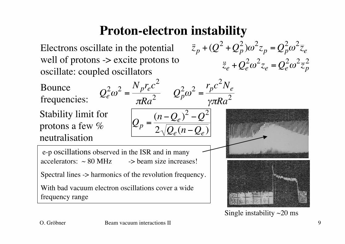
Proton-electron instabilityElectrons oscillate in the potentialwell of protons -> excite protons tooscillate: coupled oscillators
e-p oscillations observed in the ISR and in manyaccelerators: ~ 80 MHz -> beam size increases!
Spectral lines -> harmonics of the revolution frequency.
With bad vacuum electron oscillations cover a widefrequency range
€
˙ ̇ z p + (Q2 +Qp2 )ω2zp = Qp
2ω2z e
€
˙ ̇ z e +Qe2ω2ze = Qe
2ω2z p2
€
Qe2ω2 =
Nprec2
πRa2
€
Qp2ω2 =
rpc2Ne
γπRa2Bouncefrequencies:
€
Qp =(n −Qe )
2 −Q2
2 Qe(n −Qe )Stability limit forprotons a few %neutralisation
Single instability ~20 ms
O. Gröbner Beam vacuum interactions II 10
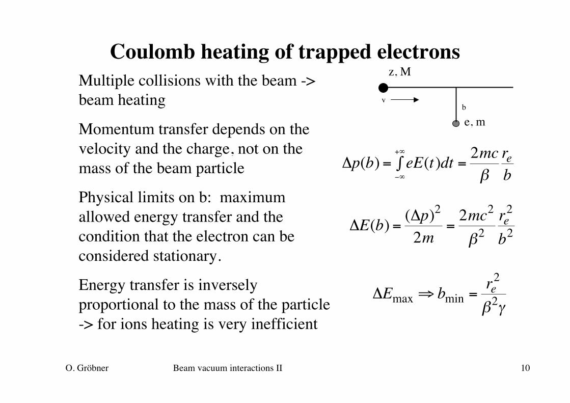
Coulomb heating of trapped electronsMultiple collisions with the beam ->beam heating
Momentum transfer depends on thevelocity and the charge, not on themass of the beam particle
Physical limits on b: maximumallowed energy transfer and thecondition that the electron can beconsidered stationary.
Energy transfer is inverselyproportional to the mass of the particle-> for ions heating is very inefficient
€
ΔE(b) =(Δp)2
2m=2mc2
β2re2
b2
€
ΔEmax ⇒ bmin =re2
β2γ
z, M
bv
e, m
€
Δp(b) = eE(t)dt−∞
+∞
∫ =2mcβ
reb

O. Gröbner Beam vacuum interactions II 11
Electron heating by multiple scattering (ISR)
€
d2Nb(r)dt
=Nb
2πRπa2βc 2πrdr
€
ρ =Nb
2πRπa2
€
dEdt
=4re2mc2Ibea2
ln rmaxrmin
Numerical example ISR:I = 20 A, R= 150 m, a = 0.01 mRmax = vacuum chamber = 0.04mγ= 28. beam potential ~ 2kVHeating rate ~ 680 eV/sClearing rate ~0.3/s
€
ΔE(b) =2mc2
β2re2
b2
€
d2E(r)dt
=2re2mc2
βcNbRπa2
drr
€
Ib = eNbc2πR
€
bmin =reβ2γ
r
dr
Beam section
O. Gröbner Beam vacuum interactions II 12
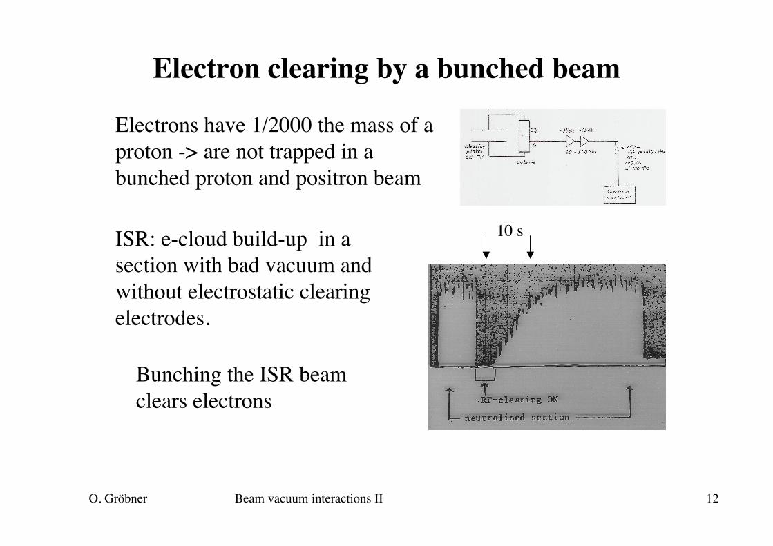
Electron clearing by a bunched beam
Electrons have 1/2000 the mass of aproton -> are not trapped in abunched proton and positron beam
ISR: e-cloud build-up in asection with bad vacuum andwithout electrostatic clearingelectrodes.
Bunching the ISR beamclears electrons
10 s

O. Gröbner Beam vacuum interactions II 13
Ion impact energy
Bunched beams: heavy ionsintegrate the passage of manybunches and see an averagefield.Light ions gain a more energy,since they see the peak field.Final energy depends on theinitial position in the beam
Ions are repelled by the positive space charge and hit the wall with asignificant energy -> several keV
Ion energy in LHCM = 2, 4, 28, 44, 500
O. Gröbner Beam vacuum interactions II 14
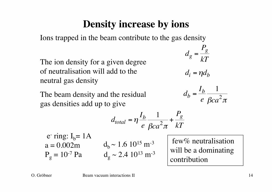
Density increase by ionsIons trapped in the beam contribute to the gas density
€
db =Ibe
1βca2π
The ion density for a given degreeof neutralisation will add to theneutral gas density
The beam density and the residualgas densities add up to give €
di =ηdb
€
dg =PgkT
€
dtotal =ηIbe
1βca2π
+PgkT
e- ring: Ib= 1Aa = 0.002mPg = 10-7 Pa dg ~ 2.4 1013 m-3
db ~ 1.6 1015 m-3 few% neutralisationwill be a dominatingcontribution
O. Gröbner Beam vacuum interactions II 15
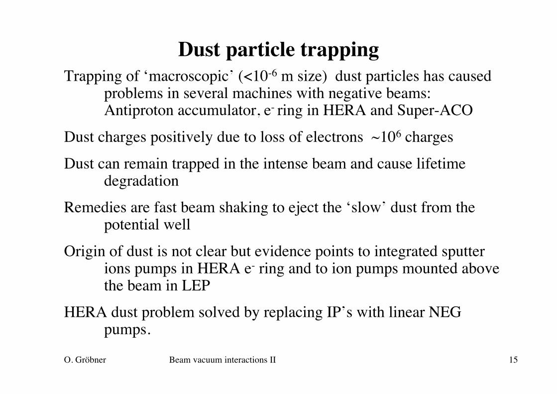
Dust particle trappingTrapping of ‘macroscopic’ (<10-6 m size) dust particles has caused
problems in several machines with negative beams:Antiproton accumulator, e- ring in HERA and Super-ACO
Dust charges positively due to loss of electrons ~106 chargesDust can remain trapped in the intense beam and cause lifetime
degradationRemedies are fast beam shaking to eject the ‘slow’ dust from the
potential wellOrigin of dust is not clear but evidence points to integrated sputter
ions pumps in HERA e- ring and to ion pumps mounted abovethe beam in LEP
HERA dust problem solved by replacing IP’s with linear NEGpumps.
O. Gröbner Beam vacuum interactions II 16
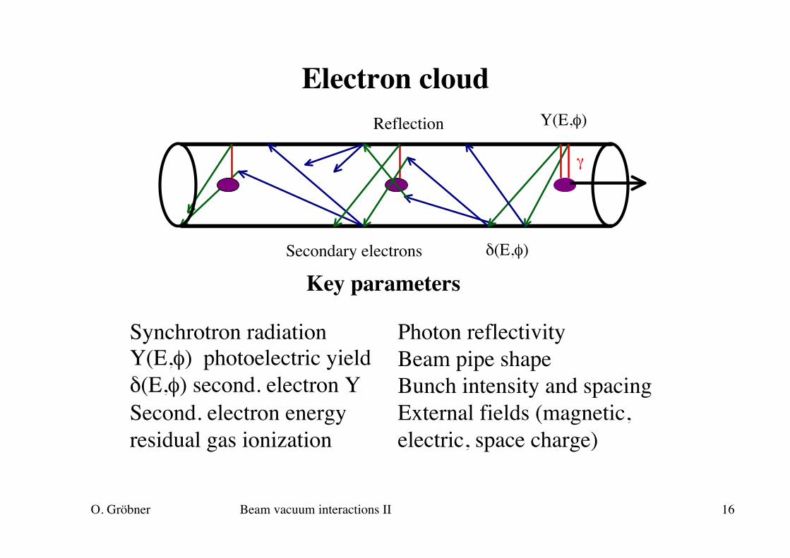
Electron cloud
δ(E,φ)
Y(E,φ)
γ
Reflection
Secondary electrons
Synchrotron radiationY(E,φ) photoelectric yieldδ(E,φ) second. electron YSecond. electron energyresidual gas ionization
Photon reflectivityBeam pipe shapeBunch intensity and spacingExternal fields (magnetic,electric, space charge)
Key parameters

O. Gröbner Beam vacuum interactions II 17
Electron cloud multipacting
€
E(r) =λ
2πε0r
€
Δp = eEτ =e2nb2πε0cr
€
Lbb = ctbb€
Δv =Δpm
= 2crenbr
€
2rpv
= tbb
The electric field of a bunchwith the line density λ and β∼1
Momentum transfer by thebunch is independent on thebunch length τ
Velocity gained by an electron
Condition for wall-to-wall multipacting
€
λ =enbβcτ
rpBeam pipe
With
€
nb =rp2
reLbb particles per bunch
>> can occur also in a beam transfer line with a single pass
O. Gröbner Beam vacuum interactions II 18
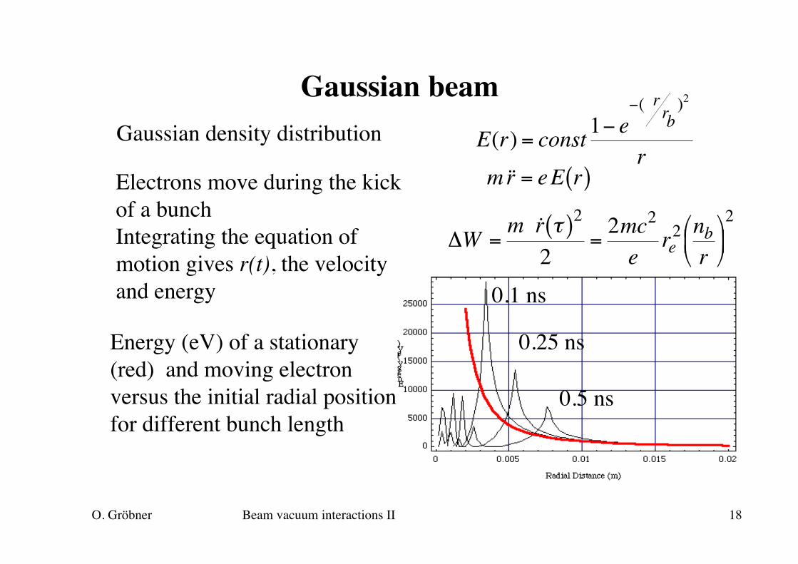
Gaussian beamGaussian density distribution
€
E(r) = const1− e−( r rb
)2
r
€
m ˙ ̇ r = eE r( )Electrons move during the kickof a bunchIntegrating the equation ofmotion gives r(t), the velocityand energy
€
ΔW =m ˙ r τ( )2
2=
2mc2
ere
2 nbr
2
Energy (eV) of a stationary(red) and moving electronversus the initial radial positionfor different bunch length
0.1 ns
0.25 ns
0.5 ns
O. Gröbner Beam vacuum interactions II 19
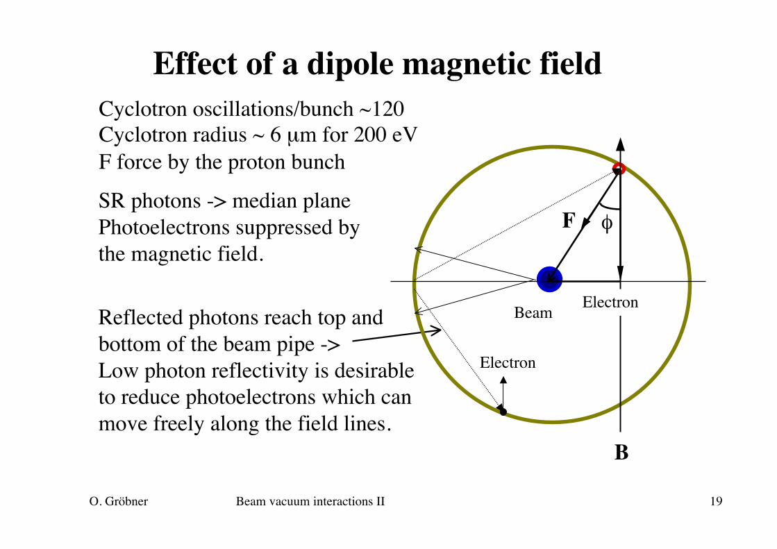
Effect of a dipole magnetic field
SR photons -> median planePhotoelectrons suppressed bythe magnetic field.
Reflected photons reach top andbottom of the beam pipe ->Low photon reflectivity is desirableto reduce photoelectrons which canmove freely along the field lines.
Cyclotron oscillations/bunch ~120Cyclotron radius ~ 6 µm for 200 eVF force by the proton bunch
B
φF
Electron
ElectronBeam
O. Gröbner Beam vacuum interactions II 20
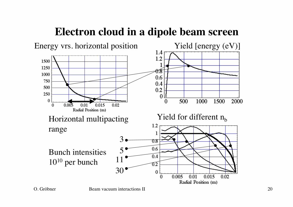
Electron cloud in a dipole beam screen
Energy vrs. horizontal position Yield [energy (eV)]
Yield for different nb
35
1130
Horizontal multipactingrange
Bunch intensities1010 per bunch

O. Gröbner Beam vacuum interactions II 21
Beam screen in an LHC dipoleELECTRON CLOUD SCREEN (addition)
BANDS OF CLOUD ELECTRONS
Strip with saw tooth
O. Gröbner Beam vacuum interactions II 22

O. Gröbner Beam vacuum interactions II 23
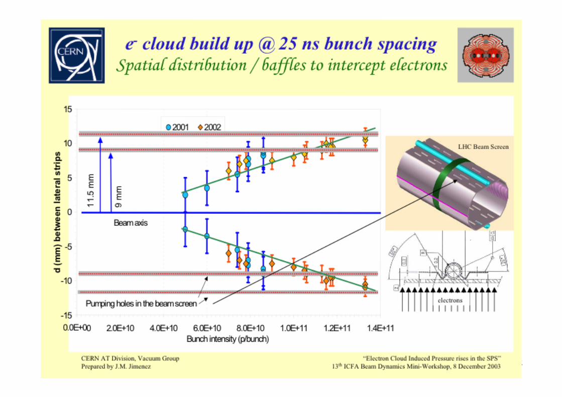
Pressure increase due to BIMGas load, Qcloud is related to the power deposited bythe electrons, Pcloud, to the molecular desorption yield,ηe and to the average energy of the electrons in thecloud, <Ecloud>.
€
Qcloud = k ηePcloud< Ecloud>
0
1
2
3
4
5
6
7
8
9
0.0E+00 1.0E+12 2.0E+12 3.0E+12 4.0E+12 5.0E+12 6.0E+12 7.0E+12
Number of protons
Rel
ativ
e P
mb
ar in
crea
se
VG50660 Dipole magnetic fieldVG51880 No magnetic field
Courtesy M. Jimenez
LHC cooling limit: Pcloud ~ 1 W/m -> 10-6 mbar l/s/m

O. Gröbner Beam vacuum interactions II 24
Reduction of BIM with beam dose
MAX SEY vs photon dose at EPACritical energy 194 eV
0.00
0.50
1.00
1.50
2.00
2.50
1.E+18 1.E+19 1.E+20 1.E+21 1.E+22 1.E+23 1.E+24
Photon dose (ph/m)
100 V-45 V350 V
Sample at - 45 V
Sample at + 100 V
Sample at + 350 V
~ 1 year of nominal LHC operation
Beam scrubbing reducesthe secondary electronyield and pressure rise
y = 12e-0.9 x
1
10
100
0:00 12:00 24:00 36:00 48:00 60:00
Running hours
Rel
ativ
e P
incr
ease
VG50660
VG52260
y = 10e-0.9 x
Gauges placed between dipoles
Running hours SPS
Photon dose in EPA
Courtesy V.Baglin
Courtesy M. Jimenez
O. Gröbner Beam vacuum interactions II 25
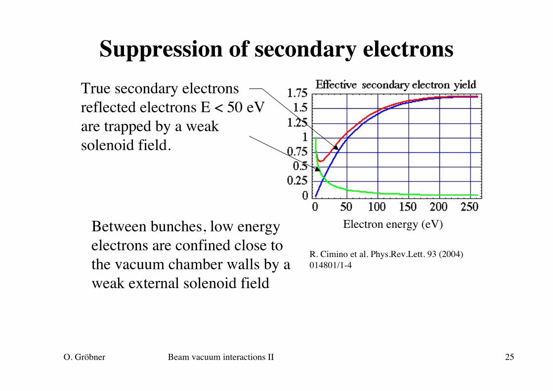
Suppression of secondary electronsTrue secondary electronsreflected electrons E < 50 eVare trapped by a weaksolenoid field.
Electron energy (eV)Between bunches, low energyelectrons are confined close tothe vacuum chamber walls by aweak external solenoid field
R. Cimino et al. Phys.Rev.Lett. 93 (2004)014801/1-4

O. Gröbner Beam vacuum interactions II 26
Solenoid field in drift chambers
€
r =mveB
€
r(m) =2me E(eV )B(T )€
tcycl = 2π meB
€
twall−wall ~πmeB
< bunch spacing
Energy (eV)
Radius (m) at 30 Gauss
r
Field (Gauss)
Trajectory time (ns)
LHC
KEKB
O. Gröbner Beam vacuum interactions II 27
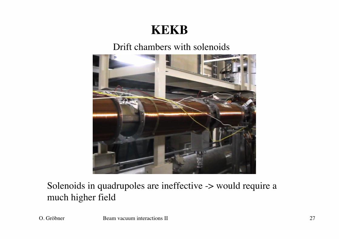
KEKBDrift chambers with solenoids
Solenoids in quadrupoles are ineffective -> would require amuch higher field
O. Gröbner Beam vacuum interactions II 28
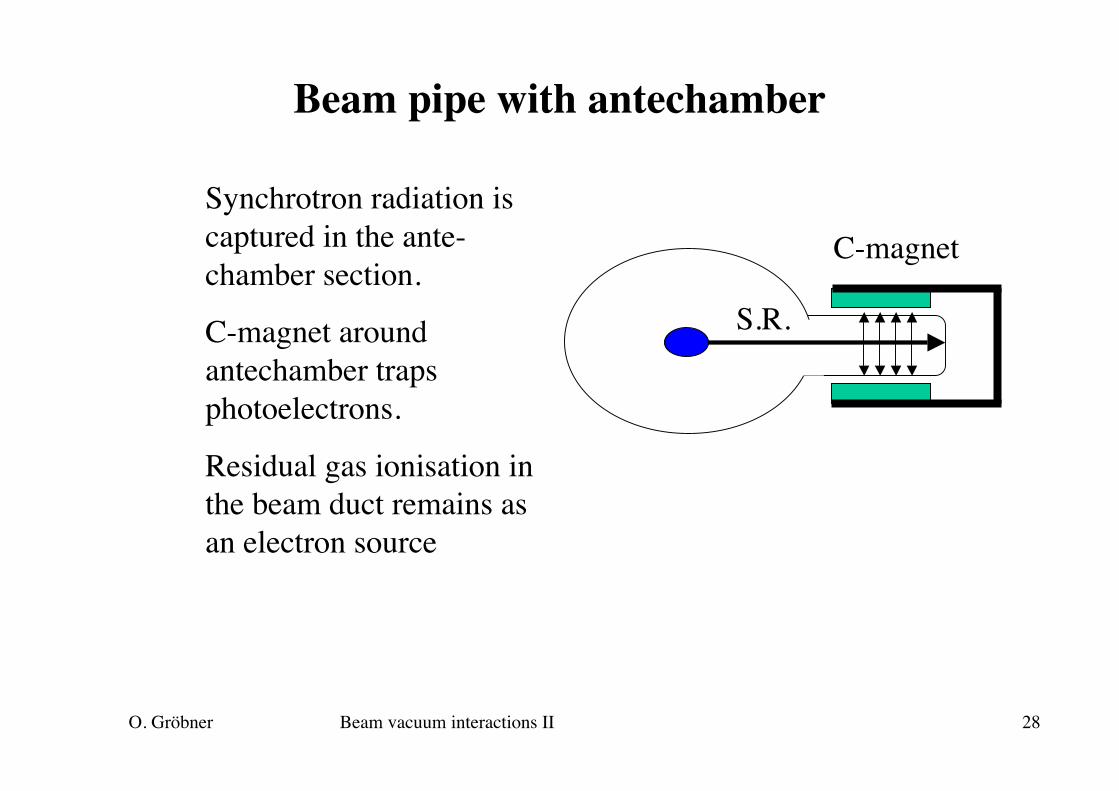
Beam pipe with antechamber
C-magnet
S.R.
Synchrotron radiation iscaptured in the ante-chamber section.
C-magnet aroundantechamber trapsphotoelectrons.
Residual gas ionisation inthe beam duct remains asan electron source
O. Gröbner Beam vacuum interactions II 29
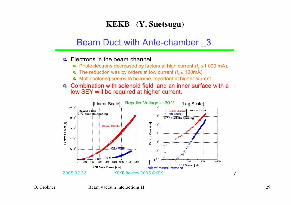
KEKB (Y. Suetsugu)
O. Gröbner Beam vacuum interactions II 30
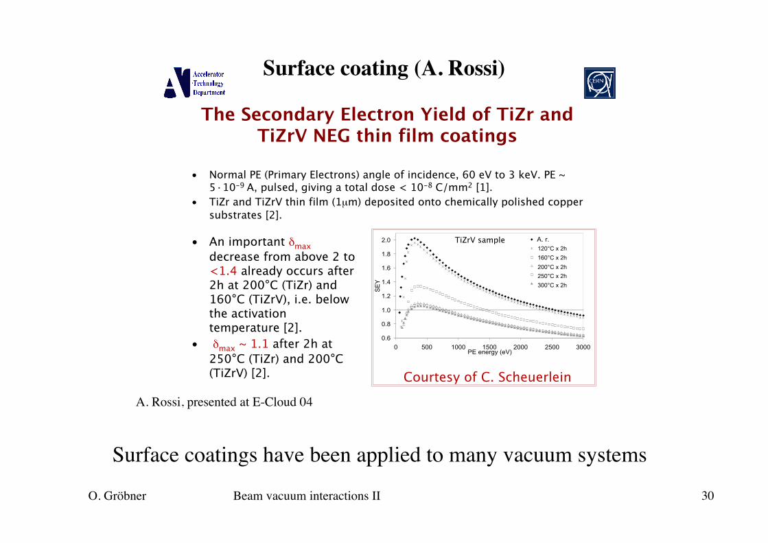
Surface coating (A. Rossi)
A. Rossi, presented at E-Cloud 04
The Secondary Electron Yield of TiZr andTiZrV NEG thin film coatings
• Normal PE (Primary Electrons) angle of incidence, 60 eV to 3 keV. PE ~5·10-9 A, pulsed, giving a total dose < 10-8 C/mm2 [1].
• TiZr and TiZrV thin film (1µm) deposited onto chemically polished coppersubstrates [2].
• An important δmaxdecrease from above 2 to<1.4 already occurs after2h at 200°C (TiZr) and160°C (TiZrV), i.e. belowthe activationtemperature [2].
• δmax ~ 1.1 after 2h at250°C (TiZr) and 200°C(TiZrV) [2].
0.6
0.8
1.0
1.2
1.4
1.6
1.8
2.0
0 500 1000 1500 2000 2500 3000PE energy (eV)
SE
Y
A. r.
2 h 120 °C 2 h 160°C 2 h 200 °C 2 h 250 °C 2 h 300 °C
120°C x 2h
160°C x 2h
200°C x 2h
250°C x 2h
300°C x 2h
Courtesy of C. Scheuerlein
TiZrV sample
Surface coatings have been applied to many vacuum systems
O. Gröbner Beam vacuum interactions II 31
ConclusionsNumerous processes exist by which the beam and the residualgas interact. The walls and surface characteristics of the vacuumsystem have a vital influence.
In addition to static and dynamic out-gassing properties, alsogeneration of electrons: photo- and secondary electrons areimportant
Electron cloud effect with its consequences on beam dynamicshas become a performance limiting effect in many accelerators
Future vacuum system designs must put emphasis on surfaceproperties of vacuum chambers and incorporate remedies for e-cloud effects to enable very high bunch currents and short bunchspacing
O. Gröbner Beam vacuum interactions II 32
Literature
CAS Vacuum Technology, CERN99-05, 19 August 1999
G. Guignard, Selection of formulae concerning proton storage rings, CERN 77-10, 6 June 1977
W. Chao, M. Tigner, Handbook of Accelerator Physics and Engineering, World Scientific1999
J. D. Jackson, Classical Electrodynamics, John Wiley & Sons, 1975
H. Wiedemann, Particle Accelerator Physics, Springer-Verlag, 1993
P. J. Bryant, K. Johnsen, The Principles of Circular Accelerators and Storage Rings, Cambridge University Press
Y. Baconnier, G. Brianti, The stability of ions in bunched beam machines, CERN/SPS/80-2, 1980
E. Keil, B. Zotter, Landau damping of coupled electron-proton oscillations, CERN-ISR-TH/71-58, 1971
D. R. C. Kelly, Dust in Accelerator Vacuum Systems, PAC 97
C. Benvenuti, R. Calder, O. Gröbner, Vacuum for particle accelerators and storage rings, Vacuum 37, 8/9, 1987
O. Gröbner, Beam induced multipacting, PAC 97