bearing strength and failure behavior of bolted glare...
TRANSCRIPT
International Journal of Mechanical & Mechatronics Engineering IJMME-IJENS Vol:16 No:02 54
161602-3838-IJMME-IJENS © April 2016 IJENS I J E N S
Bearing Strength and Failure Behavior of Bolted
GLARE Joints Mohammed Y. Abdellah
1,3*, Mohamad K. Hassan
2,3, T. Mandourah
3, Ahmad F. Mohamed
3,4
1Mechanical Engineering Department, Faculty of Engineering, South Valley University, Qena, Egypt, 83521
2Production Engineering and Design Department, Faculty of Engineering, Minia Universities, Minia, Egypt, 61111
3Mechanical Engineering Department, Collage of Engineering and Islamic Architecture, Umm Al-Qura University,
Makkah, KSA 4Mechanical Engineering Department, Faculty of Engineering, Sohag University, Sohag, Egypt
Abstract-- Glass fiber reinforced aluminum laminates
(GLARE) are main important types of fibre metal laminates
composite material. The composite sandwich is manufactured by
inserting glass fibre composite laminate between two chemically
treated aluminium thin sheet. GLARE material is manufactured
with three stacking sequences using random mate layered glass
fibre of 1, 2, and 4 layers. The strength and failure of
mechanically fastened glass fiber aluminum reinforced epoxy
(GLARE) joints are experimentally investigated. The results
indicate that bearing strength of GLARE increases with
increasing number of glass fiber reinforced laminates but with
limitation of that thickness not largely increasing to avoid
delamination. Modes of failure for the bolted joint are enhanced
to bearing modes for all types of specimens.
Index Term-- GLARE, Bolted Joint, Aluminum, Reinforced
Glass Fiber, X-FEA
INTRODUCTION
Fiber-metal laminates (FMLs) are considered hybrid structure
which are composed of glass fiber and aluminum alloy. These
materials are widely used in A380 Airbus aircraft industry [1].
Joints of composite material in aircraft industry are facing a
lot of problems especially for mechanical fixation such that
hole elongation and bolt bending under compressive loading
due to low bearing stiffness of composites [2]. Many
researchers studied and examined the behavior of fastener
joints and their effect on specimen geometry and fiber
orientation [3, 4].
Xiao and Ishikawa [2] studied strength and failure of the
mechanical fastened composite joint. They studied the effect
of polymer matrix properties on bearing strength response of
joint. They concluded that bearing failure was due to
compressive damage accumulation and it had four stages;
damage initiation; damage growth and structural fracture.
Established failure modes are; fiber microbuckling; matrix
cracking; delamination and out of plane shear cracks.
Xiao and Ishikawa [5] proved and extracted an analytical
model for simulation the bearing failure and response
characteristics of bolted composite joints. The mode was
based on progressive damage finite element method. The
numerical simulation results were in good agreement with the
experimental results, but the model needs a lot of experience
in numerical knowledge.
Hung and Chang [6] studied the effect of clamping pressure
and lateral constraint on the bolted joint. They developed a
two-dimension damage accumulation model, but the
delamination due to bearing damage was not completely
described.
Camanho et al. [7] experimentally investigated the damage
mechanisms of double lap joint with finger tight washer. It
was summarized that failure modes were fiber fracture,
delamination at loaded hole, matrix cracks and fiber
microbuckling.
Mohammed et al. [8] used X-FEM procedures to simulate the
nominal strength of size effect glass fiber composite
laminates, their results were in a good agreement with the
experimental results.
Hasan et al. [9, 10] experimentally studied the mechanical
and fracture properties of GLARE. The results were
conducted that the GLARE material had increasing strengths
and ductility and young’s modulus.
The novelty of the present study is to study analytically and
experimentally bearing strength of double lab joint GLARE
material. In addition, it is to build a simple extended-finite
element method based on cohesive traction separation laws.
Moreover, it is to stop on the failure modes of such new
material.
The paper methodology is constructed as follows; in the first
paragraph manufacturing technique of GLARE are highlight.
The next paragraph the bolted joint test is outlined, then X-
FEA is explained and is built. Finally, the validation of the
numerical analysis is discussed.
Manufacture of GLARE material
The material used in the manufacturing GLARE are random
E-glass fiber, epoxy resin and aluminum alloys sheet having
0.5 mm thickness. The components mechanical properties are
listed in Table 1. The GLARE composites are fabricated using
hand lay-up technique according to reference [11]. Mainly, the
treatment of aluminum surface needs special care because it is
a dominant factor to increase debonding between aluminum
plates and glass fiber composite laminates. There are 7 steps
for aluminum surface treatment to increase debonding in
GLARE consists of, it is completely described in reference
[9]. GLARE specimens which contain 1, 2, and 4 layers of
International Journal of Mechanical & Mechatronics Engineering IJMME-IJENS Vol:16 No:02 55
161602-3838-IJMME-IJENS © April 2016 IJENS I J E N S
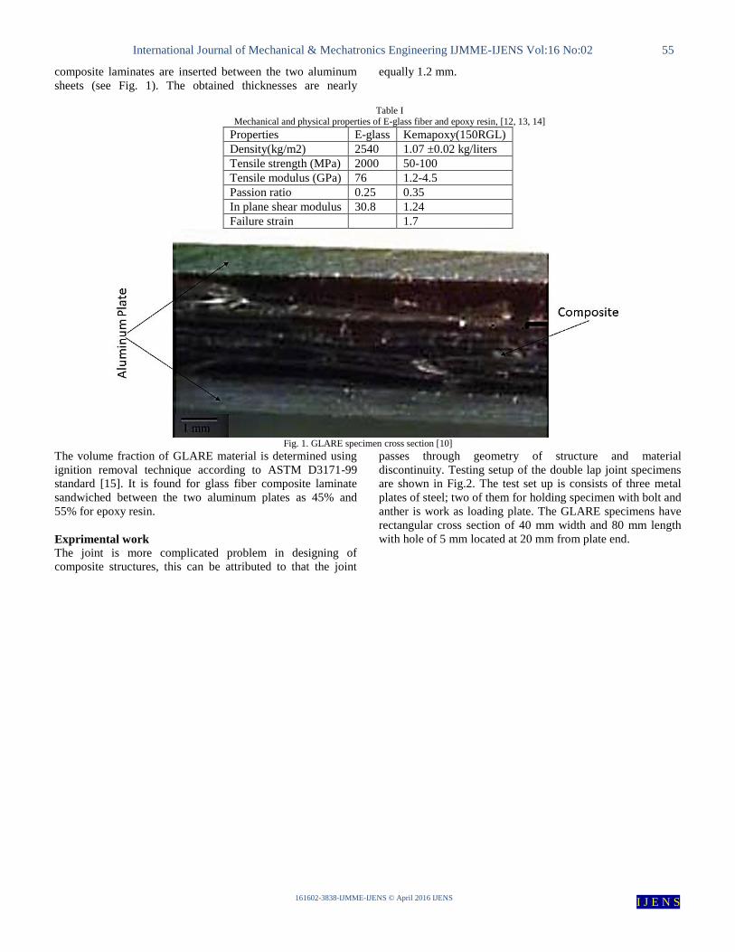
composite laminates are inserted between the two aluminum
sheets (see Fig. 1). The obtained thicknesses are nearly
equally 1.2 mm.
Table I Mechanical and physical properties of E-glass fiber and epoxy resin, [12, 13, 14]
Properties E-glass Kemapoxy(150RGL)
Density(kg/m2) 2540 1.07 ±0.02 kg/liters
Tensile strength (MPa) 2000 50-100
Tensile modulus (GPa) 76 1.2-4.5
Passion ratio 0.25 0.35
In plane shear modulus 30.8 1.24
Failure strain 1.7
Fig. 1. GLARE specimen cross section [10]
The volume fraction of GLARE material is determined using
ignition removal technique according to ASTM D3171-99
standard [15]. It is found for glass fiber composite laminate
sandwiched between the two aluminum plates as 45% and
55% for epoxy resin.
Exprimental work
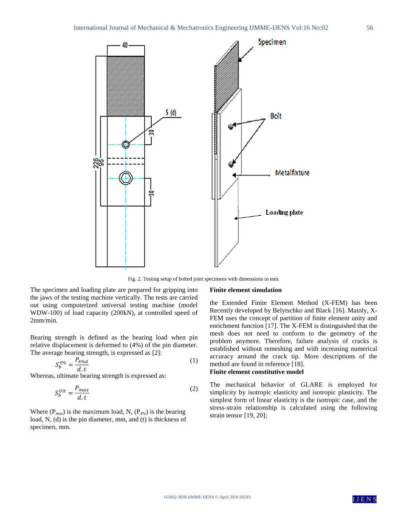
The joint is more complicated problem in designing of
composite structures, this can be attributed to that the joint
passes through geometry of structure and material
discontinuity. Testing setup of the double lap joint specimens
are shown in Fig.2. The test set up is consists of three metal
plates of steel; two of them for holding specimen with bolt and
anther is work as loading plate. The GLARE specimens have
rectangular cross section of 40 mm width and 80 mm length
with hole of 5 mm located at 20 mm from plate end.
International Journal of Mechanical & Mechatronics Engineering IJMME-IJENS Vol:16 No:02 56
161602-3838-IJMME-IJENS © April 2016 IJENS I J E N S
Fig. 2. Testing setup of bolted joint specimens with dimensions in mm.
The specimen and loading plate are prepared for gripping into
the jaws of the testing machine vertically. The tests are carried
out using computerized universal testing machine (model
WDW-100) of load capacity (200kN), at controlled speed of
2mm/min.
Bearing strength is defined as the bearing load when pin
relative displacement is deformed to (4%) of the pin diameter.
The average bearing strength, is expressed as [2]:
(1)
Whereas, ultimate bearing strength is expressed as:
(2)
Where (Pmax) is the maximum load, N, (P4%) is the bearing
load, N, (d) is the pin diameter, mm, and (t) is thickness of
specimen, mm.
Finite element simulation
the Extended Finite Element Method (X-FEM) has been
Recently developed by Belytschko and Black [16]. Mainly, X-
FEM uses the concept of partition of finite element unity and
enrichment function [17]. The X-FEM is distinguished that the
mesh does not need to conform to the geometry of the
problem anymore. Therefore, failure analysis of cracks is
established without remeshing and with increasing numerical
accuracy around the crack tip. More descriptions of the
method are found in reference [18].
Finite element constitutive model
The mechanical behavior of GLARE is employed for
simplicity by isotropic elasticity and isotropic plasticity. The
simplest form of linear elasticity is the isotropic case, and the
stress-strain relationship is calculated using the following
strain tensor [19, 20];
International Journal of Mechanical & Mechatronics Engineering IJMME-IJENS Vol:16 No:02 57
161602-3838-IJMME-IJENS © April 2016 IJENS I J E N S
{
}
[ ]
{
}
3
Where ( ) are elastic constants and
( ) are components of stress and strain. The
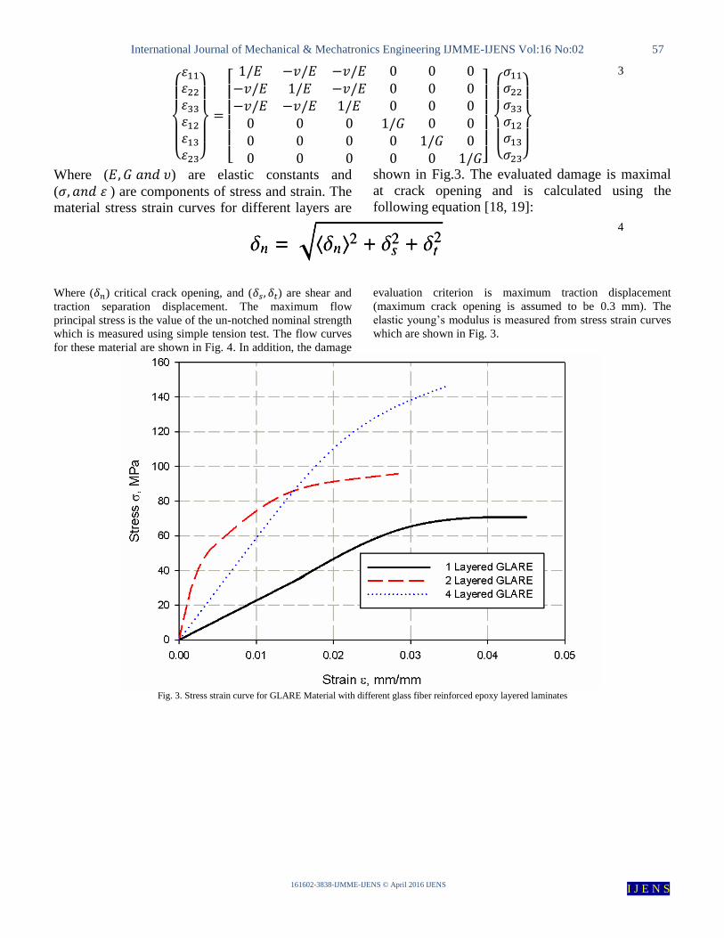
material stress strain curves for different layers are
shown in Fig.3. The evaluated damage is maximal
at crack opening and is calculated using the
following equation [18, 19]:
4
Where ( ) critical crack opening, and ( ) are shear and
traction separation displacement. The maximum flow
principal stress is the value of the un-notched nominal strength
which is measured using simple tension test. The flow curves
for these material are shown in Fig. 4. In addition, the damage
evaluation criterion is maximum traction displacement
(maximum crack opening is assumed to be 0.3 mm). The
elastic young’s modulus is measured from stress strain curves
which are shown in Fig. 3.
Fig. 3. Stress strain curve for GLARE Material with different glass fiber reinforced epoxy layered laminates

International Journal of Mechanical & Mechatronics Engineering IJMME-IJENS Vol:16 No:02 58
161602-3838-IJMME-IJENS © April 2016 IJENS I J E N S
Fig. 4. Stress strain curve for GLARE Material with different glass fiber reinforced epoxy layered laminates
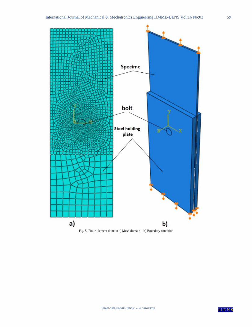
Finite element domain, mesh and boundary condition
The swept meshing technique is used to generate a domain of
1638 elements of (C3D8R) type as it is shown in Fig. (5-a).
The specimen domain is attached to the testing set up where
load is applied to the end of specimen and at the steel plate
vertically. The displacement control boundary conditions
technique is applied as it is shown in Fig. (5- b). The
interaction between the steel bolts and the holding steel plate
is assumed to be constrained as (tie) Fig. (6-a), while the
interaction between bolts and specimen domain is applied as
penalty of fraction coefficient 0.3. The domain with
interaction is shown in Fig. (6-b).
International Journal of Mechanical & Mechatronics Engineering IJMME-IJENS Vol:16 No:02 59
161602-3838-IJMME-IJENS © April 2016 IJENS I J E N S
Fig. 5. Finite element domain a) Mesh domain b) Boundary condition

International Journal of Mechanical & Mechatronics Engineering IJMME-IJENS Vol:16 No:02 60
161602-3838-IJMME-IJENS © April 2016 IJENS I J E N S
Fig. 6. Interaction domain a) Tie interaction between bolts and GLARE b) penalty between bolts and holding steel plate
RESULTS AND DISCUSSION
Bolted Joint Test:
An experimental study on the effects of bolt joints on GLARE
material panel specimens is performed. Fig. 7 illustrates load-
displacement curves of GLARE material panel specimens of
the double lap joint with 1, 2 and 4 glass reinforced composite
laminates respectively. It is observed that the maximum
bearing strength of bolt joint can be measured using Eqn. 2 at
maximum load point. These values are 89.5, 119.6 and 169.5
MPa for 1, 2 and 4 glass reinforced composite laminates
repetitively. While, average bearing strength can be measured
according to Eqn. 1 respect to Fig. 7 at (4% d) loaded pin
deformation. The values of bearing strength are measured as
60.8, 90 and 108.3 MPa for 1, 2 and 4 glass reinforced
composite laminates repetitively. Failure modes are shown in
Fig. 9, it is enhanced to be bearing failure modes for all
specimen whereas delamination observed through the
aluminum and glass fiber interfaces. The bearing mode is
confirmed due to the increasing ductility of aluminum,
whereas, wake debonding strength led to delamination through
the interface between glass fiber and the aluminum sheet.
Fig. 7. Typical load–displacement curves for bolted GLARE joint

International Journal of Mechanical & Mechatronics Engineering IJMME-IJENS Vol:16 No:02 61
161602-3838-IJMME-IJENS © April 2016 IJENS I J E N S
Finite element results validated with the experimental
Based on the experimental observation described in the
previous sections, bearing failure is mainly related by matrix
and fiber compression damage. Therefore, a cohesive damage
zone model is developed to predict the matrix compression
and fiber compression-shear failure of a laminate layer though
X-FEM. Figure 8 illustrates the X-FEA prediction for the
double lap joint bearing strength. The simulation is in good
agreement and it is observed that for one layered GLARE
sandwich X-FEM prediction is higher than experimental
results, this may due to that effect of glass fiber is wake
respect to the aluminum behavior in the GLARE material. The
failure mode is predicted in good agreement with the
experimental bearing mode as shown in Fig. 9, comparing
Von-Mises failure with the experimental failure modes.
STATUS XFEM for all simulated specimens are shown in
Fig. 10.
Fig. 8. Bearing load respect to X-FEM for a) one layered b) Two layered c) Four Layered reinforced laminates at GLARE

International Journal of Mechanical & Mechatronics Engineering IJMME-IJENS Vol:16 No:02 62
161602-3838-IJMME-IJENS © April 2016 IJENS I J E N S
Fig. 9. Predicted failure modes of GLARE material having a) one layered b) Two layered c) Four Layered reinforced laminates at GLARE
Fig. 10. STATUS XFEM of GLARE material prediction a) one layered b) Two layered c) Four Layered reinforced laminates at GLARE
CONCLUSION
In this study, a detailed experimental investigation and
numerical model are performed to evaluate the bearing
strength and damage behavior of mechanically fastened joints
of GLARE material. The relationships between the load–
displacement curve, and failure mechanism are examined. The

International Journal of Mechanical & Mechatronics Engineering IJMME-IJENS Vol:16 No:02 63
161602-3838-IJMME-IJENS © April 2016 IJENS I J E N S
bearing strength is measured at (4% d) of deformation of load
pin displacement. The failure modes are enhanced to be all
bearing due to increasing ductility of aluminum plates. X-
FEM simulates very well the bearing strength and failure
modes. The nonlinear isotropic X-FE model presented in the
paper based on cohesive law can be established for fast
prediction for selection purpose of GLARE material.
REFERENCES
[1] V. A., Chapter 1 in fibre metal laminates; an introduction, Dordrecht: Kluwer Academic Publishers; ., 2001.
[2] Y. Xiao and I. Takashi, "Bearing strength and failure behavior of bolted
composite joints (part I: Experimental investigation).," Composites Science and Technology, vol. 65, no. 7, pp. 1022-1031, 2005.
[3] L. J. Hart-Smith, "Bolted Joints In Graphite-Epoxy Composites,"
MCDONNELL DOUGLAS CORP LONG BEACH CA DOUGLAS AIRCRAFT DIV, 1976..
[4] M. FL, Joining fiber-reinforced plastics, New York: Elsevier Applied
Science, 1986.
[5] Y. Xiao and T. Ishikawa, "Bearing strength and failure behavior of
bolted composite joints (part II: modeling and simulation).," Composites
science and technology, vol. 65, no. 7, pp. 1032-1043, 2005.
[6] C. Hung and F. Chang, "Bearing failure of bolted composite joints Part
II: model and verification," Journal of composite materials, vol. 30, no.
12, pp. 1359-1400, 1996.
[7] P. P. Camanho, S. Bowron and a. F. L. Matthews., "Failure mechanisms
in bolted CFRP," Journal of Reinforced Plastics and Composites , vol.
17, no. 3, pp. 205-233, 1998.
[8] Y. Mohammed, M. K. Hassan and A. M. Hashem, "Finite Element
Computational Approach of Fracture Toughness in Composite Compact
Tension Specimen," International Journal of Mechanical & Mechatronics Engineering, vol. 12, no. 4, pp. 57-61, 2012.
[9] M. K. Hassan, M. Y. Abdellah, S. K. Azabi and W. Marzouk,
"Investigation of the Mechanical Behavior of Novel Fiber Metal Laminates," International Journal of Mechanical & Mechatronics
Engineering, vol. 15, no. 3, pp. 112-118, 2015.
[10] M. K. Hassan, M. Y. Abdellah, S. K. Azabi and W. Marzouk, "Fracture Toughness of a Novel GLARE Composite Material," International
Journal of Engineering & Technology, vol. 15, no. 6, pp. 36-41, 2015.
[11] M. A. Ardakani, A. A. Khatibi and S. A. Ghazavi, "A study on the
manufacturing of Glass-Fiber-Reinforced," in Proceedings of the XIth
International Congress and Exposition, Orlando, Florida USA, 2008.
[12] M. Y, H. M. A. E.-A. H. and H. A.M, "Size effect analysis of open-hole
glass fiber composite laminate using two-parameter cohesive laws.,"
Acta Mechanica, vol. 226, no. 4, pp. 1027-1044, 2014.
[13] J. R.M., Mechanics of Composite Materials, London: Taylor & Francis,
1999.
[14] M. P.K., Fiber-Reinforced Composites, New York: Marcel Dekker Press., 1993.
[15] ASTM., D3171-99 , Stander Test method constituent content of
composite materials, American Society of testing and materials, 1999.
[16] B. T. and B. T., "Elastic crack growth in finite elements with minimal
remeshing," Int.J. Numer Meth Engng, vol. 45, no. 5, p. 601; 620, 1999.
[17] M. J.M. and B. I, "The partition of unity finite element method: Basic theory and applications," Comput Meth App Mechs Engrg, pp. 289-314,
1996.
[18] M. Y. Abdellah, M. S. Alsoufi, M. K. Hassan, H. A. Ghulman and A. F. Mohamed, " Extended Finite Element Numerical Analysis of Scale
Effect in Notched Glass Fiber Reinforced Epoxy Composite," Archive of
Mechanical Engineering, vol. 62, no. 2, pp. 217-236, 2015.
[19] ABAQUS, Version ”6.9 Documentation.”, Providence, RI:
DassaultSystemesSimulia Corporation, 2009.
[20] N. S. Korim, M. Y. Abdellah, M. Dewidar and A. M. Abdelhaleem, "Crushable Finite Element Modeling of Mechanical Properties of
Titanium Foam," International Journal of Scientific & Engineering Research, vol. 6, no. 10, pp. 1221-1227, 2015.