bearing training manual - nachi · pdf file1. introduction to nachi america inc. •...
TRANSCRIPT

BEARING TRAINING MANUAL

www.nachiamerica.com
Nachi’s Complete Line ofBall and Roller Bearings
Deep Groove Ball BearingsOpen, Sealed, Shielded
10 mm to 200 mm Bore DiametersSeries: 6800, 6900, 6000, 6200, 6300
Angular Contact Ball BearingsSingle Row and Double Row
10 mm to 150 mm Bore DiametersSeries: 7000, 7200, 7300, 7900
Series: 5200, 5300
Super Precision Bearings10 mm to 150 mm Bore Diameters (ABEC 7)
Ball Screw Support (TAB)Small Ball (BNH)
Double Row Cylindrical (NN3000)
Cylindrical Roller BearingsSteel, Brass, or Nylon
10 mm to 200 mm Bore DiametersN, NU, NJ, NUP ConfigurationsSeries: 200, 2200, 300, 2300
Inch & Metric Tapered Roller BearingsInterchangeable Metric Design
20 mm to 100 mm Bore DiametersSeries: 30200, 30300
Series: 32000, 32200, 32300
Double-Row Spherical Roller BearingsSteel or Brass Cage, and Vibrating Screen Designs
25 mm to 320 mm Bore DiametersSeries: 22200, 23200, 21300, 22300, 23000
Series: 23100, 23900, 24000, 24100
Spherical Roller Thrust BearingsSteel or Brass Cage
60 mm to 300 mm Bore DiametersSeries: 29300, 29400
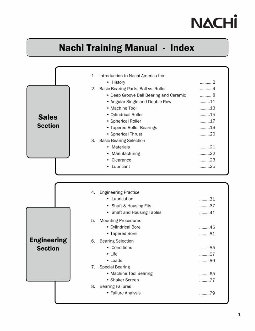
1. Introduction to Nachi America Inc.• History
2. Basic Bearing Parts, Ball vs. Roller• Deep Groove Ball Bearing and Ceramic• Angular Single and Double Row• Machine Tool• Cylindrical Roller• Spherical Roller• Tapered Roller Bearings• Spherical Thrust
3. Basic Bearing Selection• Materials• Manufacturing• Clearance• Lubricant
• Shaft & Housing Fits
………..2 ………..4 ………..8 ………11 ………13 ………15 ………17 ………19 ………20
………21 ………22 ………23 ………25
………37
5. Mounting Procedures• Cylindrical Bore• Tapered Bore
4. Engineering Practice• Lubrication
• Shaft and Housing Tables
6. Bearing Selection• Conditions• Life • Loads
7. Special Bearing• Machine Tool Bearing• Shaker Screen
8. Bearing Failures• Failure Analysis
………45………51
………31
………41
………55………57………59
………65………77
………79
Nachi Training Manual - Index
Sales Section
Engineering Section
1

1920's Nachi Fujikoshi started manufacturing hacksaw blades with highquality steel in Toyama Japan.Steel mill started operation.High Speed, Alloy Tool and Bearing Steels.Saw Blades, Drills, Taps, End Mills, and Hobs.Creation of Ball Bearing Plant, and Machine Tool Plant.Expansion Period for current business and future business.Broach bars and broaching Equipment are introduced.Roller Bearings added to bearing product line.Became a comprehensive machine manufacturer. Shaper and shaver cutters, Christmas Tree Broaches.First in Japan to Manufacture of Spherical Roller Bearings.Began production of Hydraulic Equipment.Production of high performance products.Advancements in Carbide tools.Bearings supplied for Jet Engines and Bullet Train.Production of Hydraulic Pumps and Valves.Organized Heat Treatment Technology.Established Nachi America Inc.Established Machine Tools & Hydraulic Div.Began production of Industrial Furnaces & Coating Equipment.Export Internationally.Precision Roll Forming Machines.Powered High Speed Steels.Develop Hydro-Logic systems.Automotive Air Conditioner Bearings.
1930's
1940's
1950's
1960's
1970's
BearingsCutting Tools
Broaching Machines
Gear Cutting & Forming Tools Furnace
Specialty Steel
Robotics
Specialty Steel
2

.
Wheel Bearings (high speed train)Broach Machine
Hydraulic Equipment Solenoid Valves
Precision Machine
Robotics
1980's Established Robot & Precision Machinery DivisionPromote shift of production to overseas plantsCreations of Precision Machinery Division Grinding EquipmentIntroduction of Coated ToolsWelding and Painting RobotsNeedle Bearings for CVJAwarded TPM Award (Total Productive Maintenance)Hydraulic Wheel MotorsSupplying Hardened Bar (Drill blanks)Vacuum Heat Treated FurnacesMechatronics (Combining Engineering Curriculums)Automotive Hydraulics DivisionAwarded Deming PrizeProduct Handling RobotsRadial Bearing RedesignSpherical Roller Bearing RedesignDevelopment of High Speed Specialty SteelsImprovement in Coating TechnologiesExpand Global BusinessRefinement of Specialized Cutting ToolsHigh Speed Broaching EquipmentSealed Ball Screw Support BearingsHydraulics for Mobile EquipmentHigh Performance Bearing SteelExpanded Aqua Flat Drill SeriesAdded Gear Shape Machining CenterExpanded Lineup of Extremely High Speed RobotsIncreased Local Bearing Production in Multiple CountriesSpherical Roller Bearing Re-design
1990's
2000's
Drills
Coating Equipment
3
20 0's

What is a Bearing?The American Bearing Manufacturers Association, ABMA, defines a bearing as anymechanical component used to reduce friction and guide motion.
Lever Wedge Wheel Screw Inclined Plane Pulley
Half of the six simple machines have shafts which rotate. As the shafts spin faster and as the loads increase, sliding friction causes the simple shaft supports to operate too hot.
Anti-Friction Bearings are the solution as they operate with much less friction,resulting in lower operating temperatures and are capable of accepting heavy loads.
• MaterialBearing rings and rolling elements are normally manufactured from AISI 52100 Vacuum Degassed Bearing Steel. AISI 52100 is the most commonly used steel for anti-friction bearings. SUJ2 is the Japanese equivalent in steel. Nachi has our own steel mill in Toyama Japan. We use steel from our plant or from other Japanese Steel Plants. The secret in bearing steel is in the cleanliness rating as our bearing steels are in the range of 6 parts per million or better. This makes the parts less susceptible to failure, thus extending our bearings' lives.
Retainers or cages are manufactured in several ways. Some are steel stampings, othersare steel stampings held together with rivets, some are machined brass, others are fiberglass reinforced molded nylon. The retainer design and material type is offered to enhance the performance of the specific type of bearing.
Bearings have Four Components
Inner Ring Fits around shaft
Outer Ring Fits inside housing
Balls or Rollers Rotate in grooves in the inner ring and outer ring, we call these grooves Raceways.
Cage or RetainerSeparates and spacesout the balls or rollers.
4

Bearings are divided into two groups - Ball and Roller. The balls in ball bearingstransfer the loads over very small areas on the raceways; we describe this aspoint contact. The rollers in roller bearings transfer the loads over larger areaswith the raceways; we describe this as line contact.
Point Contact enables ball bearings to operate at high speeds since the rolling friction is very low. However, the point contact limits the amount of load the bearingcan accept. So ball bearings can operate faster, but with lighter loads.
Line Contact causes more friction which limits the operating speed of rollerbearings. The larger contact areas also increases the load carrying ability ofroller bearings. So roller bearings operate slower with heavier loads.
• Types of LoadingRadial bearings are primarily designed for carrying radial loads.A radial load is a pressing force that is perpendicular to the shaft.A thrust or axial load is a force that is parallel to the shaft.
Ball & Roller Bearings
5
Radial Load
Thrust or Axial Load
Radial Load
Line ContactPoint Contact
Bearing Types

30º - 40º
Bearing Type High Loading Application Page Speed Orientation
1. Ball Bearings
Electric MotorsHydraulic MotorsGear Box Reducers
BrakesCentrifugal PumpsPositive DisplacementClutchesLight Duty Grinding
AngularContact
6
8
9
13
11
14
13
11
14
12
Sealed ShieldOpen
15º - 25º
30º - 40º
60º
Machine Tool Spindle BearingsRotary JointsSuperchargers
Air Knives, MedicalCentifugal PumpsVertical Hollow Shaft Motors
CompressorsBall Screw Support Bearings
Machine Tool Spindle BearingsRotary JointsSuperchargers
Air KnivesVertical Hollow Shaft MotorsPumps, Compressors
Ball Screw Support BearingsMedical
ClutchesBrakesPulleysPumpsGear Box
15º - 25º
60º
Duplex MountedAngular Contact
Double RowAngular Contact
20º
30º
Deep Groove
Bearing Types

Misalignment Capabilities - Mounted Units for Fabricated Industrial Equipment
7
Bearing Type High Loading Application Page Speed Orientation
2. Roller Bearings
Gear BoxPumpsMotorsTransmissions
Compressors
Tapered RollerBearing
15
16
19
17
18
20
Expansion
Cylindrical Roller Bearing
Centrifugal & PositiveDisplacement PumpsFansGear BoxHammer MillsShaker Screens
Double Row Spherical Roller
Bearing
Spherical Roller Thrust Bearing
Gear BoxPumpsTransmissionsGrinders
Centrifugal PumpsUnderground TrenchingPlastic ExtrudingEarth Boring EquipmentMunicipal Vertical ShaftPump Motors
Misalignment Capabilities
Bearing Types

The deep groove ball bearing is the most commonly used bearing in the world today. Nachi's design has a ball which is about 60% of the cross section of the bearing. This design with the larger balls is the high capacity design.
These are Conrad radial ball bearings. The balls are loaded in between the inner ring and outer ring. The outer ring is pushed out of round and the
inner ring will pass down between the balls. The balls can now be spaced out and the retainer installed. Most world class bearing manufacturers use the big ball design, and since the Conrad design will permit a maximum number of balls most major manufacturers will have around the same capacity.The higher the capacity the longer the bearing life.
The capacity of a bearing will be the same regardless if is open, has seels, or shields. All three bearings will accept the same load and produce the same life. The three bearings will have different speed limits. Speed limits are determined by how hot the bearing will operate. The higher the
speed the higher the operating temp. The open bearing has the highest speed limit. The shielded bearing will come in second, as the grease in the bearing is contained and will generate some additional temperature. The seals in the sealed bearing contact the inner ring and this contact will generate the most additional heat so the sealed bearings have the lowest speed limits of the three. Speed limits are in the catalog and are for reference as all applications are not the same and if the bearing operating temperature can be reduced the bearing can operate faster. Maximum bearing operating temperature is 250º F. (120º C)
Nachi's design utilizes a groove in the inner ring and the seal contacts the side of the groove. Standard material for seals is Buna - Nitrile Rubber.
MetalShield“ZE”
Non-contactRubber Seal“NKE”
Contact RubberSeal “NSE”
8
Deep Groove Ball Bearings

6300 Series
6200 Series
6000 Series
6900 Series
Bearings are like building blocks. We have manysize ball bearings which have the same bore size.As the cross section of the ball bearing gets largerthe bearing can handle heavier loads, with slowerspeed limits than the thinner bearings.
Bearings can also have common OD sizes. Again,the bearings with the larger cross-sections willhandle the heavier loads and slower speeds.
Bearings can have common OD, bores andwidths across bearing types.
M NR C3
C2 = less than CNCN = C0 = Normal Clearance, Standard outside the U.S.C3 = Greater than CN, Standard in the U.S.C4 = Greater than C3
NR = Snap Ring and Groove N = Snap Ring Groove in Outer Ring OD
M = Bronze Cage (Large Bore) -- = Standard Stamped Steel Cage
-2NSE = Buna-Nitrile Rubber Light Contact Seals on Both Sides for 55 mm Bore and Larger
11 = Bore Code x 5 is Bore Size in mm = 11 x 5 = Ø55 mm Exceptions:
62
= Single Row Deep Groove Ball Bearing= Available Series 6800, 6900, 6000, 6200 & 6300
62 11 -2NSE
G = Polyamide Cage, (Reinforced Nylon)
Same bore
Same O.D.
9
= Buna-Nitrile Rubber Light Contact Seals on Both Sides for 10 mm to 50 mm Bore= Buna-Nitrile Rubber Light Contact Seal on One Side for 55 mm Bore and Larger= Buna-Nitrile Rubber Light Contact Seal on One Side for 10 mm to 50 mm Bore= Metal Shields on Both Sides= Metal Shield on One Side
00 = Ø10 mm01 = Ø12 mm02 = Ø15 mm03 = Ø17 mm
Internal Clearance:
Ring Modification:
Cage Type:
Closures:
-2NSE9 NSE
NSE9 ZZE
ZE -2NKE
-2NKE9 NKE
NKE9 --
= Buna-Nitrile Rubber Non-Contact Seals on Both Sides for 10 mm to 50 mm Bore= Buna-Nitrile Rubber Non-Contact Seal on One Side for 55 mm Bore and Larger= Buna-Nitrile Rubber Non-Contact Seal on One Side for 10 mm to 50 mm Bore= Open Bearing (No Seals or Shields)
= Buna-Nitrile Rubber Non-Contact Seals on Both Sides for 55 mm Bore and Larger
Bore Size:
Bearing Type and Dimension Series: 6800 Series
Deep Groove Ball Bearings

10
Ceramic Hybrid Deep Groove Ball Bearings
The primary application for Ceramic Hybrid Deep Goove Ball bearings is for electric current isolation in electric motors, traction motors, and power generation equipment. These bearings are also used for high speed industrial equipment applications such as routers, lathes, and CNC machinery.
Due to the Silicon Nitride, or ceramic, rolling elements being smaller rotating mass, the limiting speed is 1.25 times faster than that of a comparable bearing size with standard steel rolling elements.
The standard configuration for these bearings is double steel shielded and Exxon Polyrex® EMgrease.
Silicon Nitride (Ceramic)Rolling Elements
Double Shielded

-- = Stamped Steel Retainer
-- = Bearing Contact Angle 30°
11
Bearings with the suffix “U” can be used in pairs. The inner ring and the outer ring have identical widths. Thispermits the bearings to be arranged in any combinationsuch as back to back, face to face or tandem pairs.
Angular Contact Ball Bearings
Single Row
The single row angular contact ball bearing was designed to support thrust loads in one direction and radial loads. The thrust capacity is achieved by a higher shoulder on one side of the outer ring. The direction of the load through the balls forms
increases with the contact angle. Contact angles are 15°, 25°, 30° or 40° depending on the bearing type.
Universal Ground Angular Contact Ball Bearings
B M U C3
C3 = Greater than CN
U = Universal Ground Rings for Universal Mounting
M = Machined Brass Retainer
B = Bearing Contact Angle 40°
C = Bearing Contact Angle 15°
= Bore Size is 5 x 11 = Ø55 mm
72 = Angular Contact Ball Bearing (Types 7000, 7200, 7300)
72 11
Over Incl.
10 ~ 18 18 ~ 32
18 ~ 30 20 ~ 40
30 ~ 40 25 ~ 45
40 ~ 50 30 ~ 50
50 ~ 65 35 ~ 60
65 ~ 80 40 ~ 65
80 ~ 100 55 ~ 80
100 ~ 120 60 ~ 85
120 ~ 140 75 ~ 105
140 ~ 150 85 ~ 115
Axial Internal ClearanceBore (mm)
2A ( m)
11
AC = Bearing Contact Angle 25°
Y = Molded Polyamide Retainer
Axial Internal Clearance:
Ring Configuration:
Cage Type:
Contact Angle:
Bore Size:
Bearing Type and Dimension Series:

Internal Clearance: C2 = less than CN -- = CN = C0 = Normal ClearanceC3 = Greater than CN
Angular Contact Ball Bearings
Double row angular contact bearings can be supplied open, sealed or shielded. Clearance Ranges for angular contact bearings are dependent on series. Angular contact machine tool bearings are
,bl
A -2NS NR C3
NR = Snap Ring and Groove in Outer Ring ODN = Snap Ring Groove in Outer Ring OD
Closures: 2NS = Rubber Seals on Both Sides
NS = Rubber Seal on One SideZZ = Metal Shield on Both Sides
Z = Metal Shield on One Side-- = Open Bearing (no Seals or Shields)
A = Bearing Contact Angle 30°-- = Bearing Contact Angle 20°
11 = Bore Size is 5 x 11 = Ø55 mm
52 = 5200 Double Row Angular Contact Ball Bearing (Types 5200, 5300)
52 11
12
Ring Modification:
Contact Angle:
Bore Size:
Bearing Type and Dimension Series:
Double RowDouble row angular contact ball bearings correspond, in principle, to two single row angular contact ball bearings with either a 20° or a 30° contact angle in the back-to-back arrangement. Double row bearings are narrower than two of the same bearing size.
Double row angular contact ball bearings are usedfor radial loads, and can also carry thrust in either direction. Their radial load-carrying capacity is not double the corresponding single row bearing but is 1.55 times the single row bearing for a 20º contact angle and 1.47 times for a 30º contact angle.

Back-to-Back"DB"
Face-to-Face"DF"
Tandem"DT"
Class 4P4P4
ABEC7
Class 2P2P2
ABEC9
Class 6P6P6
ABEC3
Class 5P5P5
ABEC5
Normal ClassP0P0
ABEC1
Machine Tool Bearings
Angular Contact Ball Bearings for the Machine Tool Industry are broken into two categories: Spindle Bearings & Ball Screw Support Bearings. Both types of bearings are manufactured to P4 or P5 precision classifications.
Spindle bearings are normally stocked as universal pairs or universal singles. Universal bearingscan be arranged into any configuration.
When bearing are used in duplex sets, orpairs, the bearings need to be special ormatched sets. Bearings are very stiff and for both bearings to accept the loads evenly the bearings should be matched.
We stock some angular contact bearings as universal ground indicating the width of the rings inthe bearings are identical and these bearings can be used in any of the three arrangements.
Single row angular contact bearings are supplied open, only ball screw support bearings have optional seals. Clearance ranges for single row angular contact bearings are dependent on bearing series. Angular Contact Machine tool bearings are normally supplied with negative clearance commonly referred to as preload.
Precision LevelStandard Level
"DB" "DF" "DT"
Spindle Bearings
13
ISOJISDIN
ABMA

DB = 2 Bearings in Back-to-Back Arrangement
TAB = Ball Screw Support Bearing (Bearing Contact Angle 60º) Bore Size: 35 = Bore size 35 mm.
07
07 DU 2LR GM P4
P4 = ABEC 7 = Super Precision
GM = Medium Preload (Standard)
2LR = Rubber Seals on Both Sides2NKE = Non-Contact Seals on Both Sides
-- = Open
DU = 2 Bearings Universal GroundU = 1 Bearing Universal Ground
DF = 2 Bearings in Face-to-Face ArrangementDT = 2 Bearings in Tandem Arrangement
= Indicator of Base 70mm OD. This bearing is 72 mm.
35 TAB
C Y DU GL P4
P4 = ABEC 7 =Super Precision
GL = Light Preload (Standard)GE = Extra Light Preload
GM = Medium Preload GH = Heavy Preload
DU = 2 Bearings Universal GroundU = 1 Bearing Universal Ground
DB = 2 Bearings in Back-to-Back ArrangementDF = 2 Bearings in Face-to-Face ArrangementDT = 2 Bearings in Tandem Arrangement
Y = Polyamide Resin CageT = Phenolic Cage
C º51 elgnA tcatnoC gniraeB =AC = Bearing Contact Angle 25º
11 = Bore Size is 5 x 11 = 55mm
70 = 7000 Angular Contact Ball Bearing (Types 7900,7000,7200)
70 11
14
Tolerance Class:
Preload:
Cage Type:
Contact Angle:
Bore Size:
Bearing Type and Dimension Series:
Ring Configuration:
Tolerance Class:
Ring Modification:
Ring Configuration:
:
Bearing Type:
Closures:
PO = ABEC 1 = Standard Precision
PO = ABEC 1 = Standard Precision
GL = Light Preload (Standard)
GH = Heavy Preload
2NSE = Contact Seals on Both Sides
Ball Screw Support Bearings

Cylindrical Roller Bearings
Cylindrical roller bearings are designed to accept heavy radial loads. We show six families of parts for each bore size. The boundary dimensions match radial ball bearings.
For each size there are many ring configurations (types) as shown below. The type depends on the ribs on the inner and outer ring. The most common types are the NU and NJ. NU has two ribs on the outer ring and no ribs on the inner ring, this type cannot accept thrust load. This configuration is often used a an espansion bearing. The NJ has two ribs on the outer ring and one rib on the inner ring, this type can accept a small thrust load in one direction.
For each size and configuration there are two designs. The Standard Design and the Large Roller High Capacity Design. In addition to configurations and type, there are various retainer designs.
Larger Diameter Rollers increase the capacity of the bearing which increases bearing life.
Cage Material
Symbol
Cage Material
Big Roller
Low viscosity Oil
High Temperature
Low Noise
Low Cost
Brass
MY
Brass
EL
Steel
: Excellent : Good : Fair : Poor
-
Excel SeriesStandard
Feat
ure
Nylon Steel
EG EJ
NU N NJ NF NUP NH
StandardType
ExcelType
15

Bearing Life [ hrs. ]
Failu
re R
atio
[ %
]
NU307EG
NU307
EG
16
Standard Capacity Design Excel High Capacity Design
MY
97.5
90
70
50
30
20
10
5
210 2 5 100 2 5 1000 2 5
= Series 1000, 200, 2200, 300, 2300200
NU E G C3
C3 = Greater than CN
G = Nylon Molded CageJ = Stamped Steel CageL = Brass Cage
MY = Machined Brass Cage-- = Stamped Steel Cage
E = High Capacity Design-- = Standard Design
07 = Bore size is 5 x 7 = Ø35 mm.
NU = Configuration Option (NU, N, NJ, NF, NUP, NH)
2 07
Internal Clearance:
Dimension Series:
Cage Type:
Internal Design:
Bore Size:
Bearing Type:
CN = Normal Clearance
C4 = Greater than C3

Double Row Spherical Roller Bearings
Double Row Spherical Roller Bearings are the work horse of the industry. Their spherical shaped outer ring and barrel shaped rollers permits this bearing to operate with 2º of misalignment with no reduction in bearing life.
For the last two decades Nachi has had the highest load ratings in the world. Bearing life is directlyrelated to Load Ratings. Larger diameter rollers relates to less stress, less stress relates to longerbearing life. Stamped steel retainer coupled with floating aligning ring permits longer length rollers.
All Nachi Spherical Roller Bearings are heat stabilized so the bearings can operate to 400º F with no reductions in Bearing Life.
ConventionalDesign
EXQ Design
Largesize
roller
17
A special variation of spherical roller bearings for vibrating screen applications is detailed on Page 77 of this training guide.

Double Row Spherical Roller Bearings
Most of the Spherical Roller Bearings brought into North America have W33 relube grooves and holes. Nachi offers nine series of Spherical Roller Bearings which permits the best bearing selectionfor our customers.
EX W33 K C3
C3 = Greater than CN
K = Tapered Bore (1/12)
-- = Straight Bore
W33 = Lubrication Groove and Holes in Outer RingW20 = Lubrication Holes in Outer Ring
-- = No Lubrication Groove or Holes in Outer Ring
EXQ = High Capacity DesignEXQ-V = High Capacity Design (Vibrating Screen Design)
AEX = Asymmetric DesignE = Standard Design
18 = Bore Size is 5 x 18 = Ø90 mm.
23 = This is the 22300 Series (Nine different series available)
2 = Indicates this is a Spherical Roller Bearing
2 23 18
239230 240
213 223
222 232
241
231
W33
W20
18
Symmetric Roller DesignFloating Guide FlangePressed Steel Cage
Asymmetric Roller DesignFixed Guide Flanges
Machined Brass Cage
Internal Clearance:
Bore Style:
Internal Design:
Bore Size:
Dimension Series:
Ring Modification:
Bearing Type:
CN = Normal Clearance
K30 = Tapered Bore (1/30)

3
Bearing Features:Advanced inner ring rib design provides:
• Superior roller guidance for better efficiencies• Sliding motion between the inner ring flange and the roller end is the primary heat
generation source. We have optimized the design of this critical area to reduce heat build up.
All contacting bearing components are made from the cleanest Japanese steels. These materials increase the life of the bearings over conventional steel.
Metric Series:30203 - 3022030303 - 3031432004 - 3202232205 - 3221832304 - 32311
E 3 0 2 06 JE….J
06 = Bore is 06 x 5 = 30 mmIndicates metric series complieswith ISO standard Interchangeablecup & cone
02 = Series 02, 03, 2, 22 or 23
= Tapered Roller BearingsH-E….JH indicates the bearing rings aremanufactured from case carburizedsteel for higher loading.
Thin section, high strength, stamped steelcages maximize the lubrication flow, which improves the lubrication factor resulting in longer bearing life.
19
Inch and Metric Tapered Roller Bearings
E J
Contact Nachi for information on ourInch Series Tapered Roller Bearings
Bore Size:
Dimension Series:
Bearing Type:

Spherical Roller Thrust Bearings
150% to 200% Increase in Bearing Life:Maximizing the roller diameter, effective length, and number of rollers yields the highest possible dynamic load capacity design. Our new EXS1 design allows for this dramatic increase in bearing life.
Faster Speed Capability:We developed a new stamped steel retainer to increase lubricant flow and enhance our design toimprove the sliding motion between the inner ring flange and roller ends. This reduces heat generation by 10% and increases the limiting speeds by 10%.
Quieter Operation and Reduced Vibration Level: We implemented a unique super finish process and improved roller roundness and raceway accuracy, which reduced noise and vibration level by more than 40% over other manufacturers bearings.
Size Range:EXS1 Series 29317 to 29326EXS1 Series 29412 to 29430
E Series 29328E to 29360EE Series 29432E to 29456E
EXS1 Design
20
MY = Brass Cage -- = Steel Cage
E = Standard Capacity
15 = Bore is 15 x 5 = Ø75 mm
3 = Diameter Series (3 or 4)
29 = Spherical Roller Thrust Bearing
29 3 15 EXS1 --
EXS1 = Updated Design
Internal Design:
Cage Type:
Bore Size:
Dimension Series:
Bearing Type:
E Design

MaterialRolling bearings are manufactured from special steel alloys that possess high strength, wear resistance, dimensional stability, excellent fatigue resistance and freedom from internal defects.
The bearing rings and rolling elements are usually fabricated from vacuum-degassed, high carbon, chrome bearing steel that is hardened to 60-63 Rockwell C. The most common alloy is designated AISI 52100 through-hardened steel, which is capable of operating temperatures up to approximately250º F (120º C). This same material can further be ‘heat stablized’ to endure operating temperatures up to 400º F (200º C). Operating bearings above these temperature limits will reduce the hardness of the steel and result in significantly reduced bearing life.
Some larger bearing types can also be produced with case hardened steel where only the surface is hardened. The use of this steel limits the chances of fracture leading to catastrophic failure.
The selection of retainer material is equally important. Many bearing materials may be used such as brass, steel, polymers, and composites. In general, the maximum temperature limits for the retainers exceed those of the bearing.
Seals and shields are often incorporated into many bearing types. Shields are usually made of low-carbon steel and in most cases do not pose a controlling temperature limitation. Seal materials are Buna-Nitrile Rubber (NBR), which has a temperature limit of 250º F (120º C), Polyacrylic Rubber (ACM) can be used up to 300º F (150º C), and Viton Fluoroelastomer (FPM) can withstand temperatures up to 400º F (200º C).
ManufacturingBearing rings are made from solid bars, seamless tubing, or forged rings. The exact process is dependent on bearing ring dimensions and order quantity. Balls and rollers are cold or hot headed from wire or bar stock depending on size.
The individual components are turned to rough size, hardened and drawn in an atmosphere controlled furnace. All components are ground to final size. Grinding consists of Face Grinding, External Grinding, Internal Grinding and Honing.
All of the steps during assembly are dependent on bearing type.
Bearing Materials
21
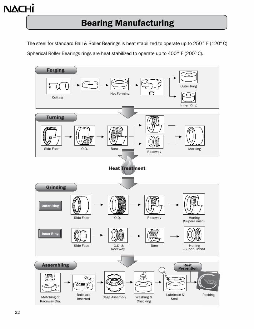
Bearing Manufacturing
The steel for standard Ball & Roller Bearings is heat stabilized to operate up to 250° F (120º C)
Spherical Roller Bearings rings are heat stabilized to operate up to 400° F (200º C).
Raceway
Bore
Side Face
Side Face
O.D.
O.D. &Raceway
Honing(Super-Finish)
Outer Ring
Inner Ring
CuttingHot Forming
Outer Ring
Inner Ring
Matching ofRaceway Dia.
Balls areInserted Cage Assembly
Lubricate &Seal
Packing Washing & Checking
Side Face O.D. BoreRaceway
Marking
22
Honing(Super-Finish)
Assembling
Grinding
Turning
Forging
Heat Treatment
RustPrevention
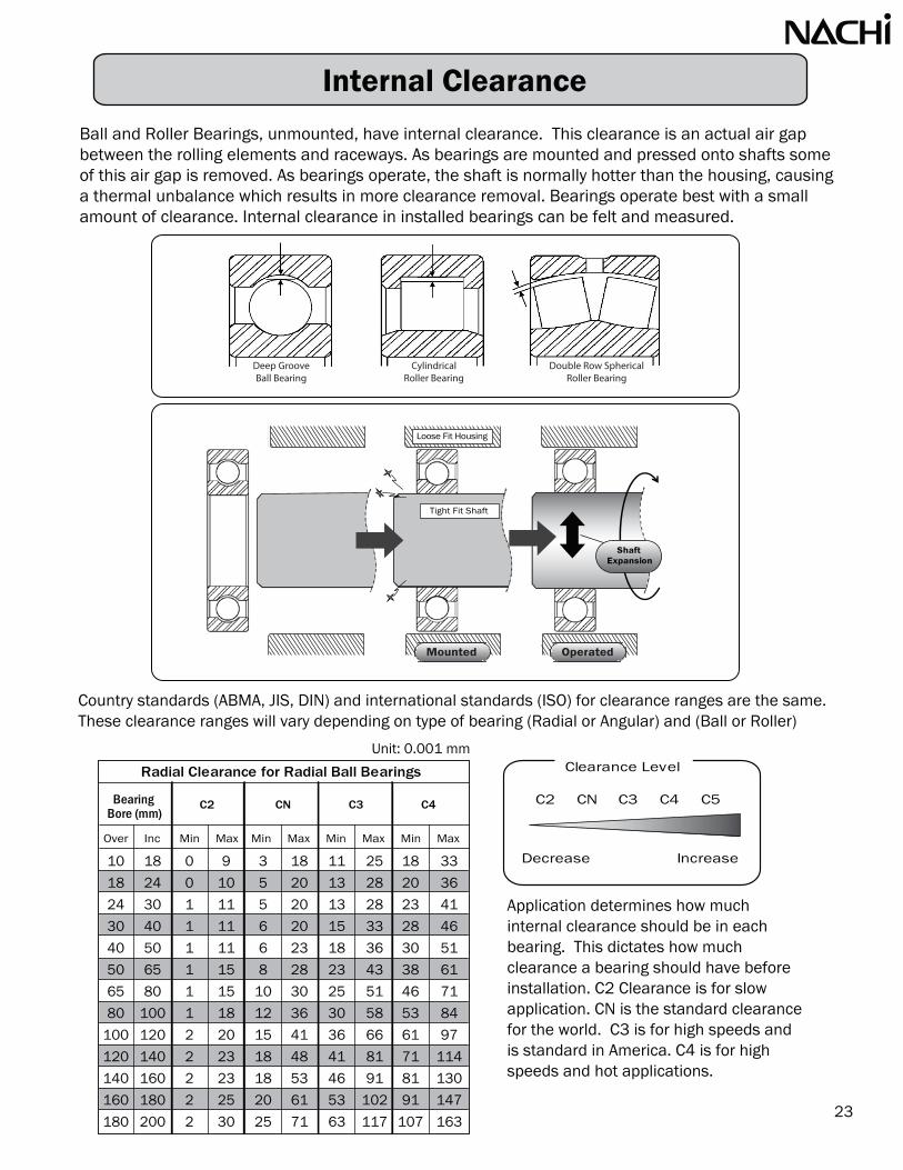
Internal Clearance
Ball and Roller Bearings, unmounted, have internal clearance. This clearance is an actual air gapbetween the rolling elements and raceways. As bearings are mounted and pressed onto shafts some of this air gap is removed. As bearings operate, the shaft is normally hotter than the housing, causing a thermal unbalance which results in more clearance removal. Bearings operate best with a small amount of clearance. Internal clearance in installed bearings can be felt and measured.
Country standards (ABMA, JIS, DIN) and international standards (ISO) for clearance ranges are the same.These clearance ranges will vary depending on type of bearing (Radial or Angular) and (Ball or Roller)
Application determines how muchinternal clearance should be in eachbearing. This dictates how muchclearance a bearing should have beforeinstallation. C2 Clearance is for slow application. CN is the standard clearance for the world. C3 is for high speeds and is standard in America. C4 is for high speeds and hot applications.
Decrease Increase
C2 CN C3 C4 C5
Clearance Level
23
Unit: 0.001 mm
Over Inc Min Max Min Max Min Max Min Max
BearingBore (mm)
Radial Clearance for Radial Ball Bearings
C2 CN C3 C4
0
0
1
1
1
1
1
1
2
2
2
2
2
9
10
11
11
11
15
15
18
20
23
23
25
30
3
5
5
6
6
8
10
12
15
18
18
20
25
18
20
20
20
23
28
30
36
41
48
53
61
71
11
13
13
15
18
23
25
30
36
41
46
53
63
25
28
28
33
36
43
51
58
66
81
91
102
117
18
20
23
28
30
38
46
53
61
71
81
91
107
33
36
41
46
51
61
71
84
97
114
130
147
163
18
24
30
40
50
65
80
100
120
140
160
180
200
10
18
24
30
40
50
65
80
100
120
140
160
180
aft nsion
ShExpa
Tight Fit Shaft
Operated
Loose Fit Housing
Mounted
Double Row SphericalRoller Bearing
CylindricalRoller Bearing
Deep GrooveBall Bearing

BearingBore (mm)
The table values are radial internal clearance. Radial ball bearings will have about 10 times the amount of axial clearance as radial clearance. The axial clearance is what can be felt when holding a bearing in hand and twisting the inner ring to the outer ring. Double row angular contact ball bearings have about 3 times the amount of axial to radial clearance.
Radial Clearance : A+B+C+D
Axial Clearance : E+F
Unit: 0.001 mm
Over Inc Min Max Min Max Min Max Min Max Min Max
3040506580
100120140160180200225250280
Clearance values are published in our Nachi catalogs and on our website (www.nachiamerica.com)Our website will also convert radial clearance to axial clearance for each bearing size. Roller bearings require more clearance than ball bearings so the clearances in roller bearings are larger. In general, the clearance ranges for ball bearings overlap while the clearance ranges for roller bearings do not.
Radial Clearance for Spherical Roller Bearing
Stra
ight
Bor
e
C2 CN C3 C4 C5
24
40506580
100120140160180200225250280315
152020303540506065708090
100110
30354050607595
110120130140150190190
30354050607595
110120130140150190190
45556580
10012014517
180200220240260280
45556580
100120145170180200220240260280
607590
110135160190220240260290320350370
80100120145180210240280310340380420460460
100125150180225260300350390430470520570630
607590
110135160190220240260290320350370
80100120145180210240280310340380420500500
Internal Clearance

Lubrication
Five Basic Functions of Lubrications:
• Reduce Friction• Reduce Wear• Reduce Temperature• Minimize Corrosion• Seal Out Contamination
Bearings cannot survive without Lubricant
Why is it Important to Lubricate Bearings?
25
Metal Oxygen
Metal
Metal Oxygen
Metal
Lubrication
FRICTION
WEARHEAT
OXIDATION

Two Basic Types of Lubricant: Grease & Oil
Grease is a very effective method for lubricating bearings because it has several advantages:
The American Society for Testing and Materials (ASTM) defines grease as: “a lubricant of fluid-to-firm consistency produced by thickening a liquid lubricant with a stable, homogenous dispersion of a solid-phase thickener and containing such additives as required to impart special characteristics.
In general terms, it is oil blended with a base thickener to give it some consistency. Additives areoften blended in to improve characteristics, such as preventing rust or improving wear resistance.
• Convenience – factory sealed and greased bearings require no maintenance• Cost Effective – a sealed and greased bearing reduces the number of parts• Grease is easier to contain than oil• Grease acts as a seal preventing the entry of contaminants inside the bearing
Greases are described in terms of the materials used to formulate them and their physical properties. The type of base oil, oil viscosity, thickener type, and thickener content are theformulation properties. Other physical properties such as consistency or penetration, torqueresistance, dropping point, evaporation loss, and water washout are determined usingstandardized tests. There are thousands of greases available on the market with a vast arrayof formulations and performance characteristics. The results of these tests help determine when a specific grease is better suited for an application over another grease.
Grease :
Additive
Thickener
Base Oil
26

Lubrication
Grease Properties
27
• ViscosityAn important property of every grease is the base fluid viscosity. Viscosity is the measurement of a fluid’sresistance to flow. Laboratory measurements of viscosity use the force of gravity to produce flowthrough a standard size tube at a controlled temperature. This measurement is called kinematic viscosity.The common units for kinematic viscosity are centistokes (cSt) or saybolt universal seconds (SUS). Ahigher base oil viscosity provides increased film thickness and load carrying capacity, while increasingfriction and heat which reduces the maximum allowable operating speed.
• PenetrationPenetration is a measure of the consistency of the grease. Consistency isdefined as the degree to which a grease resists deformation under theapplication of force. Basically, it is a measure of the stiffness or hardnessof the grease. Penetration is the depth (in tenths of a millimeter) that astandard cone penetrates a sample of the grease at standard conditions ofweight, time and temperature.
• NLGI Consistency GradesThe National Lubricating Grease Institute (NLGI) has a numerical scale for classifying the consistency ofgrease by the ASTM worked penetration. In order of increasing hardness, the consistency numbers are:
This is the lowest temperature at which a grease passes from a semisolid to a liquid state under theconditions of the test. This is determined when the first drip of the grease falls from the opening of astandardized cup. This is an indication of whether a grease will flow from a bearing at operatingtemperatures. The dropping point of a grease is well above the maximum useable temperature of thegrease.
StandardCone
GreaseSample
NLGI Consistency Grade
000
00
0
1
2
3
4
5
6
Penetration
475 ~ 445
430 ~ 400
385 ~ 355
340 ~ 310
295 ~ 265
250 ~ 220
205 ~ 175
160 ~ 130
115 ~ 85
Comparison
Ketchup
Applesauce
Brown Mustard
Tomato Paste
Peanut Butter
Vegetable Shortening
Frozen Yogurt
Smooth Paste
Cheddar Cheese Spread

Nachi Standard Greases:For Sealed And Shielded Single Row Deep Groove Ball Bearings
Popular Bearing Greases:
Water Resistance
High Speed Noise High TempLoad
Resistance Torque Low Temp
Exxon Polyrex EM
Mineral Oil Polyurea-13~338 °F
(-25~170 °C)Blue
Electric Motor
Chevron SRI2
Mineral Oil Polyurea-22~302 °F
(-30~150 °C)Dark Green
Magnetic Clutch
Shell Dollium
BRBMineral Oil Polyurea
-22~302 °F (-30~150 °C)
Purple Transmission
Shell Alvania #2
Mineral Oil Lithium-20~250 °F
(-29~121 °C)Amber
General Machinery
Shell Alvania EP2
Mineral Oil Lithium-20~250 °F
(-29~121 °C)Reddish Brown
Industrial Laundry Washer
Kyodo Yushi
MTSRLEster Oil Lithium
-40~302 °F (-40~150 °C)
Light BrownElectric Motor
Exxon Unirex N3
Mineral Oil Lithium-40~400 °F
(-40~204 °C)Green Idler Pulley
Kluber Isoflex NBU15
Synthetic Ester/Mineral
Blend
Barium Complex
-40~266 °F (-40~130 °C)
Light BeigeMachine
Tool Spindle
Mobil Grease 28
Di Ester Oil Bentonite-67~356 °F
(-55~180 °C)Red
Cold Climate Machine
Example
Performance PropertiesGrease Name
ColorOperating
TempThickenerBase Oil
Grease Name POLYREX EM ALVANIA #2 MULTEMP SRL
Nachi Grease Code
Manufacturer
NLGI Consistency Grade
Color
Thickner
Base oil
Operating Temperature Range º C
Base Oil Viscosity @ 40º C (cSt)
Base Oil Viscosity @ 100º C (cSt)
Penetration (60-strokes)
Dropping Point º C
Resistance to Load
Water Resistance
Shearing Stability
Noise Level
XM
Exxon
2
Blue
Polyurea
Mineral Oil
-25~170 (-13~338ºF)
115
12.2
284
288 (550º F)
Normal
Excellent
Excellent
Good
28
AV2
Shell
2
Amber
Lithium Soap
Mineral Oil
-25~130 (-13~266ºF)
98
9.7
287
185 (365º F)
Normal
Excellent
Excellent
Normal
MTSRL
Kyodo Yushi
3
Light Brown
Lithium Soap
Ester
-40~150 (-40~302ºF)
26
5.1
250
190 (374º F)
Normal
Excellent
Excellent
Excellent
: Excellent : Good : Fair
Lubrication

Lubrication
Compatible 0 to 30 points of changeBorderline 31 to 60 points of changeIncompatible 61 or more points of change
29
Grease Compatibility
• Beware of Mixing Different Greases!A critical motor keeps failing, even though the bearings have been replaced and lubricatedaccording to the motor manufacturer’s specifications. What is happening?
The motor repair shop removes one shield from the bearing and adds grease in the end bell of themotor to help seal out dirt, but the grease the motor shop adds is not the same grease that isalready in the bearing and they are incompatible! When two greases are mixed the results may bedisastrous.
• What Happens When Greases are Incompatible?When two incompatible greases are mixed, one of two things can happen - either the mixturehardens and will not release any of the oil, or the opposite effect, the mixture softens and releasesall of the oil. In either case, the end result is basically the same - there is no means to effectivelylubricate the bearing.
• How is Grease Compatibility Determined?Two different tests are conducted to determine if greases are compatible. First a 50/50 mixtureof the two greases is analyzed at a worked penetration of 60 strokes to see if the new grease stayswithin the same NLGI consistency grade limits. If the first test is successful, a second and moredemanding roll stability test is run. This involves running a heavy cylindrical roller at 165 rpm. Theworked penetrations of the samples are measured before and after the roll test. The compatibilityis determined by evaluating each of the greases individually, as well as for mixtures at 25%/75%,50%/50%, and 75%/25% of the two greases of interest. The penetrations are measured and theresults are plotted to illustrate the blending and shearing effects on the greases and mixtures. Thegrease compatibly is determined by comparing the measured worked penetration results after thetest to the theoretical (calculated) results expected for the mixture. The compatibility assessmentsare based on the following approximate limits on the differnece between the measured and calcu-lated penetrations.
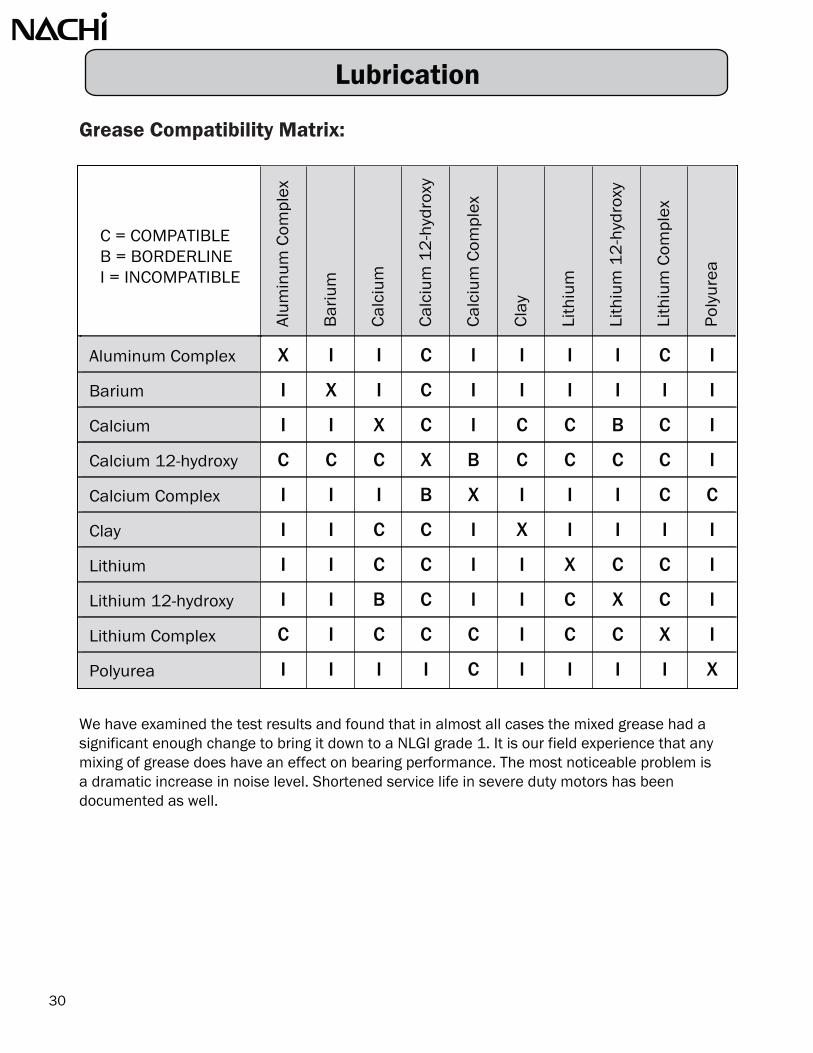
Grease Compatibility Matrix:
We have examined the test results and found that in almost all cases the mixed grease had a significant enough change to bring it down to a NLGI grade 1. It is our field experience that any mixing of grease does have an effect on bearing performance. The most noticeable problem is a dramatic increase in noise level. Shortened service life in severe duty motors has been documented as well.
Alum
inum
Com
plex
Bar
ium
Cal
cium
Cal
cium
12
-hyd
roxy
Cal
cium
Com
plex
Cla
y
Lith
ium
Lith
ium
12
-hyd
roxy
Lith
ium
Com
plex
Pol
yure
a
Aluminum Complex
Barium
Calcium
Calcium 12-hydroxy
Calcium Complex
Clay
Lithium
Lithium 12-hydroxy
Lithium Complex
Polyurea
C = COMPATIBLEB = BORDERLINEI = INCOMPATIBLE
30
X
I
I
C
I
I
I
I
C
I
I
X
I
C
I
I
I
I
I
I
I
I
X
C
I
C
C
B
C
I
C
C
C
X
B
C
C
C
C
I
I
I
I
B
X
I
I
I
C
C
I
I
C
C
I
X
I
I
I
I
I
I
C
C
I
I
X
C
C
I
I
I
B
C
I
I
C
X
C
I
C
I
C
C
C
I
C
C
X
I
I
I
I
I
C
I
I
I
I
X
Lubrication

Lubrication
How Much Grease?One of the most common misconceptions that cause a high number of bearing failures is that a bearing needs to be completely packed full. Many people have been taught ‘the more grease, the better. We have even heard of cases where people do not feel bearing manufacturers use enough grease in sealed and shielded ball bearings, so they remove one seal or shield and pack the bearing with more grease. These misconceptions are completely false. Over-lubricating the bearings forces the bearing to work harder. The best analogy we have heard is comparing running in water that is up to your ankles or running in water that is up to your neck. Which is harder? Obviously, the higher the water, the harder you have to work to move through it. This is the same for bearings. The more grease, the harder the bearing has to work to over come the friction of the excess grease.
• Nachi Standard grease-fill for sealed and shielded ball bearings is 20% to 30% full.
Too much grease can cause excess friction, thereby overheating the bearing and causing prematurefailure. Only a small amount of grease is required to lubricate a bearing in motion. When a bearing isin motion, most of the grease is pushed to the side (channeling) leaving a thin film of oil between theraceways and rolling elements. When using open bearings, pack the bearing as follows:
When the shaft speed is:50% or less of the bearings cataloged limiting speed ~ pack 1/2 to 2/3 fullGreater than 50% of the bearings cataloged limiting speed ~ pack 1/3 to 1/2 full
0
100 %
LEVEL0
100 %
LEVEL
31

Grease Lubrication
Our online catalog was used to generate the information on this chart. The information can beobtained on our website - www.nachiamerica.com. Please verify the volume output per stoke for your grease gun. Guns normally have outputs between 10 shot for one ounce to 33 shots for one ounce. This is a wide range so the grease guns should be calibrated.
Nachi's Radial Ball Bearings standard grease is EXXON Polyrex EM Grease. This grease has a polyurea thickener and is used exclusively in the motor industry. Other standard greases used by Nachi are Shell Alvania, and Kyodo Yushi Multemp SRL; both greases are lithium thickener greases.
Sealed bearings are lubricated for life. That is the life of the grease not the possible life of the bearing. On most applications, extended grease life can be achieved by relubricating ball bearings. Bearing life should not be compromised by lubrication.
This is a relubrication schedule specifically for electric motor. Notice how the two tables compare.
Relubrication guidelines for grease lubricated bearings in horizontal shaft motors with continuous operation
Relubrication Interval
Motor Speed (rpm)
32
1,200 rpm
Recommended Grease Replenishment Quantities & Intervals(for lubrication of units in service)
Bearing P/NGrease -fluid (oz)
3,600 rpm 1,800 rpm
BearingSize
Ouncesof
Grease
BearingSize
Ouncesof
Grease900 1200 1800 2700 3600
620862096210
62116212
621362146215
621662176218
0.30.30.3
0.40.4
0.50.50.6
0.70.80.9
630863096310
63116312
631363146315
631663176318
0.40.40.5
0.60.7
0.80.91.1
1.21.31.5
2 years2 years2 years
2 years2 years
2 years2 years
1.5 years
1.5 years1.5 years1.5 years
2 years1.5 years1.5 years
1.5 years1.5 years
1.5 years1.5 years
12 months
12 months12 months12 months
12 months12 months12 months
12 months12 months
6 months6 months6 months
6 months6 months6 months
6 months6 months6 months
6 months6 months
3 months3 months3 months
2 months2 months2 months
6 months6 months3 months
3 months3 months
3 months2 months2 months
1 month1 month1 month
6203 ~ 6208
6209 ~ 6309
6310 ~ 6311
6312 ~ 6317
6218 ~ 6220
0.2
0.4
0.6
0.8
1.0
2 years
1 year
1 year
1 year
6 months
3 years
2 years
2 years
1 year
1 year
3 years
2 years
2 years
1 year
2 years

Initially hand pack the bearings and fill the bearing cavity to the bottom of the shaft. Relubrication should be a function of rpm of the application.
Spherical Roller bearings used in SAF housings on horizontal shafts applications
6 months 4 months 2 months 1 months
OZ.
5 years 3 years 2 years 1 yearClean & Repack
Operating Speed (rpm)
Relube Cycle
33
BasicBearingNumber
Amountof
Grease
2220922210222112221322215222162221722218222202222222224222262222822230
0.30.60.40.80.80.91.21.72.33.14.35.56.47.9
2400220020001700145013501300120011001000900840780730
36003300300025002200200019001800165015001350125011501100
50004500400034003000280026002400220019501850170016001500
55005000450038003400320030002700230021001900180017001600
6 months 4 months 2 months 1 months
5 years 3 years 2 years 1 yearClean & Repack
Operating Speed (rpm)
Relube CycleBasicBearingNumber
Amountof Grease
oz.
2230922310223112231322315223162231722318223202232222324223262232822330
0.71.11.31.92.63.23.64.36.18.3
11.613.316.922
132512001075925800750700650600550500450425400
210019001800150013001250115011001000900800750700650
3150285027002250195018751725165015001350120011251050975
42003800360030002600250023002200200018001600150014001300
Grease Lubrication

Advantages:• Good for operation at high speeds• Circulating oil can act as a coolant• Circulating oil can remove contaminants and be filtered• Oil is suitable for extremely low or extremely high temperatures
Characteristics:• Oil is primarily used for higher speed and lighter loads• Mineral oils are the most common, however high temperatures may require synthetic oils• The quantity and type of oil varies depending on bearing type, size, load, speed…etc
Generally, oil should be replaced once per year when operating temperatures are < 120°FOil should be replaced every 90 days when operating temperatures > 200°FFor mineral oil the life of the oil halves every 15°F the oil operates over 140°FOn Synthetic oil the starting point of the lubricant life reduction is 180º F
Contamination in bearings is a constant problem. Even a small amount of contamination will affect the bearings. A hair has a diameter of about 0.003" A smoke particle is 0.0008". Contamination the size of 1 micron is at least five times the film thickness of the oil on the raceways. The contour of the raceway surfaces are in the range of plus or minus 1 micron.
Particle Sizes:(Scale: X 1,800 times) Human Hair Size
76 m(0.003 inch)
Smoke Particle Size20 m
(0.0008 inch)
1 m(0.00004 inch)
34
Oil Lubrication

The majority of the bearings in operation are lubricated with grease. Grease is 80% oil so the difference is not as large as you would expect. There are thousands of various greases. Each grease has its own operating characteristic and the Engineer has to align the bearing with the best grease for the application. On the more difficult applications, oil is many times preferred. The oil selection process is much easier than the grease selection.
It is important to select an oil having a viscosity which will work with the bearing configuration, operating temperature, rotating speed and load. If the oil viscosity is too low, the film between the raceways and the elements can be compromised too easily by the application and the bearing will prematurely wear. Anti-friction bearings are not designed to wear. Sleeve bearings are designed to wear and so sleeve bearings have acceptable wear rates. When rolling bearings wear they wear out. If the oil viscosity is too high the rotation torque will increase causing the ibearing to operate hotter and the input power would also be increased.
dn value is the bore of the bearing, multiplied by the rpm of the application. In the following chartthe units of dn are in 1,000. (example: 50 mm x 2,000 rpm = 100,000; in the chart = 100)
Viscosity is a measure of the resistance of a fluid which is being deformed by either shearor tensile stress. In everyday terms (and for fluids only), viscosity is thickness or “internalfriction”. Thus, water is “thin” having a lower viscosity, while honey is “thick” having a higher viscosity.
Bearing TypesISO viscosity grade (VG) of OilOperating
Temperature ºC
- 0º to 0º
0º to 60º
60º to 100º
100º to 150º0º to 60º
60º to 100º
Speeddn value 1000
Up to limit
Up to 15
15 to 80
80 to 150
150 to 500
Up to 15
15 to 80
80 to 150
150 to 500
Up to Limit
Up to Limit
Up to Limit
Normal Loads Heavy or Shock Loads
35
The following is a general oil selection guide.
22 32
46 68
32 64
22 32
10
150
100
68
32
46
100
68
32
22 32
220
150
100
32
All Types
All Types
All Types
All Types
All Types
All Types
All Types320
46 68
150
Oil Lubrication

The viscosity index is a widely used and accepted measure of the variation in kinematic viscosity,due to changes in the temperature of a petroleum product between 40º and 100º C.
A higher viscosity index indicates a smaller decrease in kinematic viscosity with increasing temperature of the lubricant. The viscosity index is used in practice as a single number indicatingtemperature dependence of kinematic viscosity.
36
Rule of Thumb ~ SUS @ 100° F / 5 = cSt @ 40° C
VISCOSITY CLASSIFICATION EQUIVALENTS
KINEMATICVISCOSITIES
ISO VG AGMAGrades
SAEGRADES
Auto
SAEGRADES
Year
SAYBOLTVISCOSITIES
cSt /40º C
cSt /100º C
SUS /100º F
SUS /210º F
2000
1000
800
600
500
400
300
200
150
100
80
60
50
40
30
20
10
50
30
18
15
12
10
8
7
6
5
4
1000
680
460
320
220
150
100
68
46
32
22
10
8A
8
13
7
6
5
4
3
2
1
50
40
30
20
10
5
250
140
90
85
80
75
5000
4000
3000
2000
1000
800
500
300
200
150
100
200
160
100
80
60
60
45
40
Oil Lubrication

Shaft & Housing Fits
In order for a ball or roller bearing to perform satisfactorily, the fit between the inner ring and the shaft, and the fit between the outer ring and the housing must be suitable for the application. For example, too loose of a fit could result in a corroded or scored bearing bore and shaft. While too tight of a fit could result in unnecessarily high mounting forces and too great of a reduction in internal bearing clearance. In either case, the end result could be premature bearing failure.
37
All Nachi bearings are made to tolerancesset forth by the American BearingManufacturers Association (ABMA) and the International Standards of Organization (ISO). The proper fits can only be obtained by selecting the proper tolerances for the shaft outside diameter and housing bore diameter. A letter and a number designate each tolerance. The lower case letter is for shaft fits and a capital letter is used for housing fits. The letter indicates the tolerance zone in relation to the nominal dimension and the number indicates the magnitude. The sectional rectangles shown in the image on the right, illustratethe location and magnitude of the various shaft and housing tolerance zones used for ball and roller bearings.
The selection of fit is dependent of the characteristic of the load, the bearing dimensions, the bearing operating temperature, thermal expansion of the shaft and other surrounding parts, andthe required running accuracy.
In determining suitable fits for any given application, the direction of the load with respect to the bearing ring must be known.
Red = Interference
Yellow = Transition
= Clearance
Standard Electric Motor Fit (k5)
BORE TOLERANCE
O.D. TOLERANCE
HOUSING
SHAFT
f6 g6 g5 h8 h6 h5 j5 js5 j6 js6 k5 k6 m5m6 n5 n6p6
p7 r6r7
F7 G7 G6 H10 H9 H8 H7 H6 J7 JS7 J6 JS6 K6 K7 M6 M7 N6 N7 P6 P7
Standard Electric Motor Fit (H7)
Green
Tolerance Range
Housing Bore Tolerance Range

The shaft remains stationary and the outer ring rotates. The direction of the load does not change. The entire outer ring raceway comes under load during one rotation of the housing. Only a portion of the inner ring raceway ever comes under load.Example: Pulley
The shaft rotates and the load rotates with the shaft. The outer ring does not rotate. The entire outer ring raceway comes under load during one rotation of the shaft. Only a portion of the inner ring ever comes under load.Example: Vibrating Screen
Note: the loads in these applications are radial only
• Type One
The shaft rotates and the direction of the load does not change. The outer ring is stationary. The entire inner ring raceway comes underload during one revolution of the shaft. Only a portion (an arc) of theouter ring comes under load. This is the most common application.Example: Electric Motor
In this type of application the inner ring wants to slip on the shaft and the outer ring does not want to slip in the housing. An interference fit is required between the shaft and the inner ring bore. The shaft should be slightly larger than the bearing bore. The bearing will have to be pressed onto theshaft. A loose fit is required between the outer ring OD and the housing bore. The housing is slightly larger than the bearing allowing the bearing to slide axially into the housing.
• Type Two
In these types of applications the outer ring wants to slip in the housing and the inner ring does notwant to slip on the shaft. An interference fit is required between the bearing OD and the housing.The housing will be slightly smaller than the bearing. The bearing will have to be pressed into thehousing. A loose fit is required between the bearing bore and the shaft. The shaft is slightly smaller than the bearing bore. The bearing will slide onto the shaft.
All the other applications are a slight combination of these three applications and will be notedlater in this book.
There are three most common types of applications which fit into two fitting categories:
LO
AD
LO
AD
38
• Type Three
LO
AD
Shaft & Housing Fits
Shaft Fits
1) Determine the type of bearing to be used and the bore diameter in millimeters.2) Determine which of the following load conditions is present.
a) Rotating Outer Ring Load – Such as a wheelb) Rotating Inner Ring Load – Such as an electric motor or pumpc) Rotating Inner Ring Load and High Accuracy is Required – Such as a machine tool
spindle.d) Rotating Inner Ring Load that is Considered a Heavy Load – Such as Rail Vehicles
or Rolling Mills.3) Select the proper tolerance symbol based on the following table:
Notes: Shaft tolerances in this table are for solid steel shafts for P0 or P6 bearingsFor every 0.0001” of shaft interference, you lose 0.00007” of the bearing internal clearance
Typical Bearing Loads:Heavy Load P > 0.18Cr Cr = Basic Dynamic Load RatingNormal Load 0.08Cr < P < 0.18Cr P = Equivalent LoadLight Load P < 0.08Cr
39
Ball Bearings
g6
h6
h5
j6
k6
m6
j5
k5
m5
m6
n6
p6
r6
n6
p6
r6
j6
js6
Driven Wheel
Tension Pulley orRope Sheave
Remarks
Heavy andShock Loads
Application Example
Bearings with Cylindrical Bore
RotatingOuter Ring
Load
For All Shaft Diameters
For All Shaft Diameters
When high precision isrequired, adopt g5 and h5
respectively. For largebearings, use f6 instead.
Shaft Diameter (mm)
Operating Conditions ToleranceSymbol
Axial Load Only
Light orFluctuating
Load
Rotating Inner Ring
Load orIndeterminateLoad Direction
Normal Load
Use k6 and m6 instead ofk5 and m5 for AngularContact Ball Bearings.
A bearing with larger thannormal clearance is
required.
----- -----
Locomotive Axles andTraction Motors
Electric Motors,turbines, pumps,
"Bearing applicationsin general”
Conveyors, lightlyloaded gear boxes
CylindricalRoller
Bearings
SphericalRoller
Bearings
When the innerring is requiredto move on the
shaft easily
When the innerring is NOT
required to move on the
shaft easily
When high precision isrequired, adopt j5, k5 and m5 respectively, instead of
j6, k6 and m6
up to 18
(18) to 100
(100) to 200
-----
up to 18
(18) to 100
(100) to 200
-----
-----
-----
-----
-----
-----
-----
-----
up to 40
(40) to 140
(140) to 200
-----
up to 40
(40) to 100
(100) to 140
(140) to 200
(200) to 400
-----
(50) to 140
(140) to 200
Over 200
up to 250
over 250
-----
-----
-----
-----
-----
up to 40
(40) to 65
(65) to 100
(100) to 140
(140) to 280
over 280
(50) to 100
(100) to 140
over 140

1) Determine the type of bearing to be used and the outside diameter in millimeters.2) Determine which of the following load conditions is present.
a) Rotating Outer Ring Load – Such as a wheelb) Rotating Inner Ring Load – Such as an electric motor or pump
3) Select the proper tolerance symbol based on the following table:
Notes: Housing tolerances in this table are applied to cast iron or steel housings for P0 or P6 bearings For every 0.0001” of housing interference, you use 0.0001” of the bearings internal clearance. A tighter fit may be adopted for light alloy housings.
ToleranceSymbol Outer Ring Movement Application Example
When a heavy load is applied to athin-walled housing or impact load.
Normal or Heavy Load
Light or Fluctuating Load
Heavy Impact Load
Heavy load or normal load; when the outer ring is not required to move in
axial direction Normal or light load; when it is desirable
for the outer ring to move in an axial direction
Impact load; When an unloaded condition can occur instantaneously
When a thermal condition through the shaft is present
Indeterminate load direction, light load;when extremely accurate rotation is
required When extremely accurate rotation is
required and it is desirable for the outerring to move in an axial direction.
Operating Conditions
Fluctuating Load; when extremely accurate rotation and high rigidity
are required.
Split or Solid
Housing
SolidHousing
40
SolidHousing
RotatingOuterRingLoad
IndeterminateLoad
Direction
RotatingInnerRingLoad
When HighAccuracy isRequired
P7
N7
M7
K7
J7
H7
H8
G7
N6
M6
K6
J6
Automobile Wheel(roller bearing)
Automobile Wheel(ball bearing)
Conveyor or Roller or Tension Pulley
Traction Motor
Pump or Crankshaft
Medium-sized Electric Motors
Railroad Car Axle
General Engineering
Gear Transmission
Drying Cylinder
Machine Tool Spindle withbearing O.D. > 125 mm
Machine Tool Spindle withbearing O.D. <= 125 mm
Centerless Grinder MainShaft - Fixed Bearing
Centerless Grinder MainShaft - Floating Bearing
Outer ring cannotbe moved in anaxial direction
Outer ring cannot bemoved in an axialdirection as a rule
Outer ring canbe moved in anaxial direction
Outer ring can easilybe moved in anaxial direction
Outer ring cannotbe moved in anaxial direction
Outer ring cannot bemoved in an axialdirection as a rule
Outer ring can be moved in an axial direction

(Values in Inches)
InchesMax. Min.
Bearing BoreDiameter
Shaft Diameter
Max. Min.
g6 h6 h5 j5 j6 k5
41
mm
10
121517
202530
35404550
556065707580
859095
100105110115120
125130140150160170180
190200220240
260280300
320340360380400
420440460480500
Shaft Diameter
Max. Min.
Shaft Diameter
Max. Min.
Shaft Diameter
Max. Min.
Shaft Diameter
Max. Min.
Shaft Diameter
Max. Min.
Fit in
0.0001”
Fit in
0.0001”
Fit in
0.0001”Fit in
0.0001”
Fit in
0.0001”
Fit in
0.0001”
0.3937
0.47240.59060.6693
0.78740.98431.1811
1.37801.57481.77171.9685
2.16542.36222.55912.75592.95283.1496
3.34653.54333.74023.93704.13394.33074.52764.7244
4.92135.11815.51185.90556.29926.69297.0866
7.48037.87408.66149.4488
10.236211.023611.8110
12.598413.385814.173214.960615.7480
16.535417.322818.110218.897619.6850
0.3934
0.47210.59030.6690
0.78710.98391.1807
1.37751.57441.77121.9681
2.16482.36162.55852.75532.95223.1490
3.34573.54253.73943.93624.13314.32994.52684.7236
4.92035.11715.51085.90456.29826.69197.0856
7.47917.87288.66029.4476
10.234811.022211.8096
12.596813.384214.171614.959015.7464
16.533617.321018.108418.895819.6832
6L1T
7L1T
8L1T
10L1T
11L2T
13L3T
15L4T
17L6T
19L7T
21L9T
24L10T
0.3935
0.47220.59040.6691
0.78720.98401.1808
1.37761.57451.77131.9682
2.16502.36182.55872.75552.95243.1492
3.34603.54283.73973.93654.13344.33024.52714.7239
4.92075.11755.51125.90496.29866.69237.0860
7.47977.87348.66089.4482
10.235511.022911.8103
12.597713.385114.172514.959915.7473
16.534617.322018.109418.896819.6842
0.3931
0.47170.58990.6686
0.78660.98351.1803
1.37701.57381.77071.9675
2.16432.36112.55802.75482.95173.1485
3.34523.54203.73893.93574.13264.32944.52634.7231
4.91985.11665.51035.90406.29776.69147.0851
7.47867.87238.65979.4471
10.234311.021711.8091
12.596313.383714.171114.958515.7459
16.533017.320418.107818.895219.6826
4L3T
4L3T
5L4T
6L5T
7L6T
9L8T
10L10T
11L12T
13L14T
14L16T
16L18T
0.3937
0.47240.59060.6693
0.78750.98431.1811
1.37801.57491.77171.9686
2.16542.36222.55912.75592.95283.1496
3.34653.54333.74023.93704.13394.33074.52764.7244
4.92135.11815.51185.90556.29926.69297.0866
7.48037.87408.66149.4488
10.236211.023611.8110
12.598413.385814.173214.960615.7480
16.535417.322818.110218.897619.6850
0.3933
0.47200.59020.6689
0.78690.98381.1806
1.37741.57421.77111.9679
2.16472.36152.55842.75522.95213.1489
3.34563.54243.73933.93614.13304.32984.52674.7235
4.92035.11715.51085.90456.29826.69197.0856
7.47927.87298.66039.4477
10.234911.022311.8097
12.597013.384414.171814.959215.7466
16.533817.321218.108618.896019.6834
2L3T
3L3T
4L4T
4L5T
5L6T
6L8T
7L10T
8L12T
9L14T
10L16T
11L18T
0.3937
0.47240.59060.6693
0.78750.98431.1811
1.37801.57491.77171.9686
2.16542.36222.55912.75592.95283.1496
3.34653.54333.74023.93704.13394.33074.52764.7244
4.92135.11815.51185.90556.29926.69297.0866
7.48037.87408.66149.4488
10.236211.023611.8110
12.598413.385814.173214.960615.7480
16.535417.322818.110218.897619.6850
0.3935
0.47210.59030.6690
0.78700.98391.1807
1.37761.57441.77131.9681
2.16492.36172.55862.75542.95233.1491
3.34593.54273.73963.93644.13334.33014.52704.7238
4.92065.11745.51115.90486.29856.69227.0859
7.47957.87328.66069.4480
10.235311.022711.8101
12.597413.384814.172214.959615.7470
16.534317.321718.109118.896519.6839
1L5T
1L5T
2L6T
2L7T
3L8T
4L10T
4L13T
5L15T
6L17T
7L19T
8L21T
0.3939
0.47260.59080.6695
0.78770.98451.1813
1.37821.57511.77191.9688
2.16562.36242.55932.75612.95303.1498
3.34673.54353.74043.93724.13414.33094.52784.7246
4.92165.11845.51215.90586.29956.69327.0869
7.48067.87438.66179.4491
10.236511.023911.8113
12.598713.386114.173514.960915.7483
16.535717.323118.110518.897919.6853
0.3936
0.47230.59050.6692
0.78720.98411.1809
1.37781.57461.77151.9683
2.16512.36192.55882.75562.95253.1493
3.34613.54293.73983.93664.13354.33034.52724.7240
4.92095.11775.51145.90516.29886.69257.0862
7.47987.87358.66099.4483
10.235611.023011.8104
12.597713.385114.172514.959915.7473
16.534617.322018.109418.896819.6842
1L6T
1L6T
2L8T
2L9T
3L11T
4L13T
4L16T
5L18T
6L20T
7L23T
8L26T
0.3940
0.47270.59090.6696
0.78790.98471.1815
1.37841.57531.77211.9690
2.16592.36272.55962.75642.95333.1501
3.34703.54383.74073.93754.13444.33124.52814.7249
4.92195.11875.51245.90616.29986.69357.0872
7.48097.87468.66209.4494
10.236811.024211.8116
12.599113.386514.173914.961315.7487
16.536217.323618.111018.898419.6858
0.3936
0.47230.59050.6692
0.78720.98411.1809
1.37781.57461.77151.9683
2.16512.36192.55882.75562.95253.1493
3.34613.54293.73983.93664.13354.33034.52724.7240
4.92095.11775.51145.90516.29886.69257.0862
7.47987.87358.66099.4483
10.235611.023011.8104
12.597713.385114.172514.959915.7473
16.534617.322018.109418.896819.6842
0L7T
0L7T
1L8T
1L10T
1L12T
1L15T
1L18T
2L21T
2L25T
2L27T
2L31T
0.3940
0.47280.59100.6697
0.78790.98471.1815
1.37851.57541.77221.9691
2.16602.36282.55972.75652.95343.1502
3.34723.54403.74093.93774.13464.33144.52834.7251
4.92215.11895.51265.90636.30006.69377.0874
7.48127.87498.66239.4497
10.237311.024711.8121
12.599513.386914.174314.961715.7491
16.536717.324118.111518.898919.6863
0.3937
0.47240.59060.6693
0.78750.98441.1812
1.37811.57491.77181.9686
2.16552.36232.55922.75602.95293.1497
3.34663.54343.74033.93714.13404.33084.52774.7245
4.92145.11825.51195.90566.29936.69307.0867
7.48057.87428.66169.4490
10.236411.023811.8112
12.598613.386014.173414.960815.7482
16.535617.323018.110418.897819.6852
Shaft Bearing Seat Diameters

(Values in Inches)
n6 p6 r6Bearing BoreDiameter
k6 m5 m6
InchesMax. Min.
42
mm
10
121517
202530
35404550
556065707580
859095
100105110115120
125130140150160170180
190200220240
260280300
320340360380400
420440460480500
Shaft Diameter
Max. Min.
Shaft Diameter
Max. Min.
Shaft Diameter
Max. Min.
Shaft Diameter
Max. Min.
Shaft DiameterFit in
0.0001”
Fit in
0.0001” Max. Min.
Shaft Diameter
Max. Min.
Fit in
0.0001”
Fit in
0.0001”
Fit in
0.0001”
Fit in
0.0001”
26T45T
30T54T
31T/55T33T/56T
37T64T
43T73T
45T75T
50T83T
52T86T
4.92485.1216 5.51535.90906.30276.69647.0901
7.48457.87828.66579.4532
10.241211.0286
11.816112.604113.3915
14.179114.966515.753916.541917.3293
18.117018.904419.6918
4.92395.1207 5.51445.90816.30186.69557.0892
7.48337.87708.66459.4521
10.239911.0273
11.814912.602713.3901
14.177714.965115.752516.540417.3278
18.115418.902819.6902
15T31T
17T37T
20T43T
22T49T
24T55T
27T61T
3.34883.54563.74253.93934.13624.33304.52994.7267
4.92405.12085.51455.90826.30196.69567.0893
7.48347.87718.66459.4519
10.239711.027111.8145
12.602313.398714.177114.964515.7519
16.539717.327118.114518.901919.6893
3.34803.54483.74173.93854.13544.33224.52914.7259
4.92305.11985.51355.90726.30096.69467.0883
7.48237.87608.66349.4508
10.238411.025811.8132
12.600813.398214.175614.963015.7504
16.5398117.325518.112918.900319.6877
0.3937
0.47240.59060.6693
0.78740.98431.1811
1.37801.57481.77171.9685
2.16542.36222.55912.75592.95283.1496
3.34653.54333.74023.93704.13394.33074.52764.7244
4.92135.11815.51185.90556.29926.69297.0866
7.48037.87408.66149.4488
10.236211.023611.8110
12.598413.385814.173214.960615.7480
16.535417.322818.110218.897619.6850
0.3934
0.47210.59030.6690
0.78710.98391.1807
1.37751.57441.77121.9681
2.16482.36162.55852.75532.95223.1490
3.34573.54253.73943.93624.13314.32994.52684.7236
4.92035.11715.51085.90456.29826.69197.0856
7.47917.87288.66029.4476
10.234811.022211.8096
12.596813.384214.171614.959015.7464
16.533617.321018.108418.895819.6832
0T7T
0T8T
1T10T
1T12T
1T14T
1T18T
1T21T
2T26T
2T28T
2T32T
2T36T
0.3941
0.47290.59110.6698
0.78810.98491.1817
1.37871.57561.77241.9693
2.16622.36302.55992.75672.95363.1504
3.34753.54433.74123.93804.13494.33174.52864.7254
4.92245.11925.51295.90666.30036.69407.0877
7.48177.87548.66289.4502
10.237611.025011.8124
12.600013.387414.174814.962215.7496
16.537217.324618.112018.899419.6873
0.3937
0.47240.59060.6693
0.78750.98441.1812
1.37811.57491.77181.9686
2.16552.36232.55922.75602.95293.1497
3.34663.54343.74033.93714.13404.33084.52774.7245
4.92145.11825.51195.90566.29936.69307.0867
7.48057.87428.66169.4490
10.236411.023811.8112
12.598613.386014.173414.960815.7482
16.535617.323018.110418.897819.6852
2T8T
3T9T
3T11T
4T13T
5T16T
5T19T
6T23T
7T27T
8T34T
8T38T
9T38T
0.3942
0.47300.59120.6699
0.78820.98501.1818
1.37881.57571.77251.9694
2.16642.36322.56012.75692.95383.1506
3.34763.54443.74133.93814.13504.33184.52874.7255
4.92265.11945.51315.90686.30056.69427.0879
7.48187.87558.66299.4503
10.238211.025611.8130
12.600613.388014.175414.962815.7502
16.537417.324818.112218.899619.6870
0.3939
0.47270.59090.6696
0.78770.98461.1814
1.37841.57521.77211.9689
2.16592.36272.55962.75642.95333.1501
3.34703.54383.74073.93754.13444.33124.52814.7249
4.92195.11875.51245.90616.29986.69357.0872
7.48107.87478.66219.4495
10.237011.024411.8118
12.599213.386614.174014.961415.7488
16.536317.323718.111118.898519.6859
2T9T
3T10T
3T12T
4T15T
4T18T
5T22T
6T26T
7T30T
8T34T
8T38T
9T43T
0.3943
0.47310.59130.6700
0.78830.98511.1819
1.37901.57591.77271.9696
2.16662.36342.56032.75712.95403.1508
3.34793.54473.74163.93844.13534.33214.52904.7258
4.92295.11975.51345.90716.30086.69457.0882
7.48217.87588.66329.4506
10.238211.025611.8130
12.600613.388014.175414.962815.7502
16.537917.325318.112718.900119.6875
0.3939
0.47270.59090.6696
0.78770.98461.1814
1.37841.57521.77221.9689
2.16582.36262.55952.75632.95323.1500
3.34703.54383.74073.93754.13444.33124.52814.7249
4.92195.11875.50245.90616.29986.69357.0872
7.48107.87478.66219.4495
10.237011.024411.8118
12.599213.386614.174014.961415.7488
16.536317.323718.111118.898519.6859
4T10T
5T12T
6T15T
7T18T
8T21T
9T26T
11T30T
12T36T
13T40T
15T45T
16T49T
0.3944
0.47330.59150.6702
0.78860.98541.1822
1.37931.57621.77301.9699
2.16692.36372.56062.75742.95433.1511
3.34833.54513.74203.93884.13574.33254.52944.7262
4.92335.12015.51385.90756.30126.69497.0886
7.48277.87648.66389.4512
10.238811.026211.8136
12.601313.388714.176114.963515.7509
16.538517.325918.113318.900719.6881
0.3941
0.47290.59110.6698
0.78800.98491.1817
1.37871.57551.77241.9692
2.16622.36302.55992.75672.95363.1504
3.34743.54423.74113.93794.13484.33164.52854.7253
4.92245.11925.51295.90666.30036.69407.0877
7.48157.87528.66269.4500
10.237511.024911.8123
12.599913.387314.174714.962115.7495
16.537017.324418.111818.899219.6866
39T/65T
Shaft Bearing Seat Diameters

0.74770.86580.94451.02331.10201.1808
1.25941.37751.45621.57441.65311.8499
2.04672.16492.44042.83413.1491
3.34593.54273.93644.33014.52704.7238
4.92065.11745.51115.70805.9048
6.29826.69197.0856
7.47917.87288.26658.46348.85719.44769.8413
10.234811.022211.809612.2033
12.597013.384414.171614.959015.7464
16.533617.321018.108418.895819.6832
20.470421.257822.832623.620024.4074
25.587626.375026.768727.556128.343529.524630.705731.0994
Housing Bearing Seat Diameters
mm
192224262830
323537404247
5255627280
8590
100110115120
125130140145150
160170180
190200210215225240250
260280300310
320340360380400
420440460480500
520540580600620
650670680700720750780790
J6 J7 K6
(Values in Inches)Bearing Outside
DiameterG7 H8 H7
43
InchesMin. Max.
Housing BoreMin. Max.
Housing BoreMin. Max.
Housing BoreMin. Max.
Housing BoreMin. Max.
Housing BoreMin. Max.
Housing BoreMin. Max.
Fit in0.0001”
Fit in0.0001”
Fit in0.0001”
Fit in0.0001”
Fit in0.0001”
Fit in0.0001”
0.74800.86610.94491.02361.10241.1811
1.25981.37801.45671.57481.65351.8504
2.04722.16542.44092.83463.1496
3.34653.54333.93704.33074.52764.7244
4.92135.11815.51185.70875.9055
6.29926.69297.0866
7.48037.87408.26778.46468.85839.44889.8425
10.236211.023611.811012.2047
12.598413.385814.173214.960615.7480
16.535417.322818.110218.897619.6850
20.472421.259822.834623.622024.4094
25.590626.378026.771727.559128.346529.527630.708731.1024
0.74830.86640.94521.02391.10271.1814
1.26021.37841.45711.57521.65391.8508
2.04762.16582.44132.83503.1500
3.34703.54383.93754.33124.52814.7249
4.92195.11875.51245.70935.9061
6.29986.69357.0872
7.48097.87468.26838.46528.85899.44949.8431
10.236911.024311.811712.2054
12.599113.386514.173914.961315.7487
16.536217.323618.111018.898419.6858
20.473321.260722.835523.622924.4103
25.591526.378926.772627.560028.347429.528530.709631.1033
15L3L
17L4L
21L4L
25L5L
28L6L
31L6L
36L6L
41L7L
46L7L
51L8L
56L9L
71L9L
0.74910.86720.94601.02471.10351.1822
1.26111.37931.45801.57611.65481.8517
2.04882.16702.44252.83623.1512
3.34843.54523.93894.33264.52954.7263
4.92345.12025.51395.71085.9076
6.30136.69507.0887
7.48277.87648.27018.46708.86079.45129.8449
10.238911.026311.813712.2074
12.601613.389014.176214.963615.7510
16.538717.326118.113518.900919.6883
20.476021.263422.838223.625624.4130
25.594726.382126.775827.563228.350629.531730.712831.1065
0.74800.86610.94491.02361.10241.1811
1.25981.37801.45671.57481.65351.8504
2.04722.16542.44092.83463.1496
3.34653.54333.93704.33074.52764.7244
4.92135.11815.51185.70875.9055
6.29926.69297.0866
7.48037.87408.26778.46468.85839.44889.8425
10.236211.023611.811012.2047
12.598413.385814.173214.960615.7480
16.535417.322818.110218.897619.6850
20.472421.259822.834623.622024.4094
25.590626.378026.771727.559128.346529.527630.708731.1024
17L0T
19L0T
23L0T
27L0T
32L0T
35L0T
40L0T
46L0T
51L0T
56L0T
63L0T
79L0T
0.74940.86750.94621.02501.10371.1825
1.26131.37951.45821.57631.65501.8519
2.04902.16722.44272.83643.1514
3.34863.54543.93914.33284.52974.7265
4.92385.12065.51435.71125.9080
6.30176.69547.0891
7.48317.87688.27058.46748.86119.45169.8453
10.239411.026811.814212.2079
12.602113.389514.176714.964115.7515
16.539217.326618.114018.901419.6888
20.476721.264122.838923.626324.4137
25.595526.382926.776627.564028.351429.532530.713631.1073
0.74800.86610.94491.02361.10241.1811
1.25981.37801.45671.57481.65351.8504
2.04722.16542.44092.83463.1496
3.34653.54333.93704.33074.52764.7244
4.92135.11815.51185.70875.9055
6.29926.69297.0866
7.48037.87408.26778.46468.85839.44889.8425
10.236211.023611.811012.2047
12.598413.385814.173214.960615.7480
16.535417.322818.110218.897619.6850
20.472421.259822.834623.622024.4094
25.590626.378026.771727.559128.346529.527630.708731.1024
12L0T
14L0T
17L0T
20L0T
23L0T
26L0T
30L0T
34L0T
38L0T
43L0T
48L0T
61L0T
0.74890.86700.94571.02451.10321.1820
1.26081.37891.45761.57581.65451.8513
2.04842.16662.44212.83583.1508
3.34793.54473.93844.33214.52904.7258
4.92295.11975.51345.71035.9071
6.30086.69457.0882
7.48217.87588.26958.46648.86019.45069.8443
10.238211.025611.813012.2067
12.600813.388214.175414.962815.7502
16.537917.325318.112718.900119.6875
20.475221.262622.837423.624824.4122
25.593726.381126.774827.562228.349629.530730.711831.1055
0.74780.86590.94471.02341.10221.1809
1.25961.37781.45651.57461.65331.8502
2.04702.16522.44072.83443.1494
3.34633.54313.93684.33054.52744.7242
4.92105.11785.51155.70845.9052
6.29896.69267.0863
7.48007.87378.26748.46438.85809.44859.8422
10.235911.023311.810712.2044
12.598113.385514.172914.960315.7477
16.535117.322518.109918.897319.6847
20.472121.259522.834323.621724.4091
25.590226.377626.771327.558728.346129.527230.708331.1020
7L2T
8L2T
10L2T
12L2T
14L3T
17L3T
21L3T
24L3T
27L3T
31L3T
35L3T
46L4T
0.74840.86650.94521.02401.10271.1815
1.26021.37831.45701.57521.65391.8507
2.04772.16592.44142.83513.1501
3.34713.54393.93764.33134.52824.7250
4.92205.11885.51255.70945.9062
6.29996.69367.0873
7.48127.87498.26868.46558.85929.44979.8434
10.237211.024611.812012.2057
12.599713.387114.174314.961715.7491
16.536717.324118.111518.898919.6863
20.473921.261322.836123.623524.4109
25.592226.379626.773327.560728.348129.529230.710331.1040
0.74760.86570.94451.02321.10201.1807
1.25941.37761.45631.57441.65311.8500
2.04672.16492.44042.83413.1491
3.34603.54283.93654.33024.52714.7239
4.92075.11755.51125.70815.9049
6.29866.69237.0860
7.47977.87348.26718.46408.85779.44829.8419
10.235611.023011.810412.2041
12.597713.385114.172514.959915.7473
16.534617.322018.109418.896819.6842
20.471521.258922.833723.621124.4085
25.589726.377126.770827.558228.345629.526730.707831.1015
9L4T
10L4T
12L5T
15L5T
17L6T
20L6T
24L6T
28L6T
31L7T
35L8T
39L9T
52L9T
0.74860.86670.94541.02421.10291.1817
1.26041.37851.45721.57541.65411.8509
2.04792.16612.44162.83533.1503
3.34743.54423.93794.33164.52854.7253
4.92235.11915.51285.70975.9065
6.30026.69397.0876
7.48157.87528.26898.46588.85959.45009.8437
10.237611.025011.812412.2061
12.600113.387514.174714.962115.7495
16.537117.324518.111918.899319.6867
20.474321.261722.836523.623924.4113
25.592826.380226.773927.561328.348729.529830.710931.1046
0.74760.86570.94451.02321.10201.1807
1.25931.37751.45621.57431.65301.8499
2.04662.16482.44032.83403.1490
3.34583.54263.93634.33004.52694.7237
4.92055.11735.51105.70795.9047
6.29846.69217.0858
7.47947.87318.26688.46378.85749.44799.8416
10.235111.022511.809912.2036
12.597313.384714.172114.959515.7469
16.534117.321518.108918.896319.6837
20.470721.258122.832923.620324.4077
25.588626.376026.769727.557128.344529.525630.706731.1004
4L4T
5L5T
7L6T
8L7T
9L8T
12L8T
14L9T
16L11T
19L11T
21L13T
20L17T
30L20T
0.74810.86620.94491.02371.10241.1812
1.25991.37801.45671.57491.65361.8504
2.04742.16562.44112.83483.1498
3.34673.54353.93724.33094.52784.7246
4.92155.11835.51205.70895.9057
6.29946.69317.0868
7.48057.87428.26798.46488.85859.44909.8427
10.236411.023811.811212.2049
12.598913.386314.173514.960915.7483
16.535717.323118.110518.897919.6853
20.472421.259822.834623.622024.4094
25.590626.378026.771727.559128.346529.527630.708731.1024

0.74830.86640.94511.02391.10261.1814
1.26011.37821.45691.57511.65381.8506
2.04762.16582.44132.83503.1500
3.34693.54373.93744.33114.52804.7248
4.92185.11865.51235.70925.9060
6.29976.69347.0871
7.48087.87458.26828.46518.85889.44939.8430
10.236811.024211.811612.2053
12.599313.386714.173914.961315.7487
16.536117.323518.110918.898319.6857
20.472421.259822.834623.622024.4094
25.590626.378026.771727.559128.346529.527630.708731.1024
44
0.74770.86580.94451.02331.10201.1808
1.25941.37751.45621.57441.65311.8499
2.04672.16492.44042.83413.1491
3.34593.54273.93644.33014.52704.7238
4.92065.11745.51115.70805.9048
6.29826.69197.0856
7.47917.87288.26658.46348.85719.44769.8413
10.234811.022211.809612.2033
12.597013.384414.171614.959015.7464
16.533617.321018.108418.895819.6832
20.470421.257822.832623.620024.4074
25.587626.375026.768727.556128.343529.524630.705731.0994
Housing Bearing Seat Diameters
mm
192224262830
323537404247
5255627280
8590
100110115120
125130140145150
160170180
190200210215225240250
260280300310
320340360380400
420440460480500
520540580600620
650670680700720750780790
N6 N7 P7
(Values in Inches)Bearing Outside
DiameterK7 M6
InchesMin. Max.
Housing BoreMin. Max.
Housing BoreMin. Max.
Housing BoreMin. Max.
Housing BoreMin. Max.
Housing BoreMin. Max.
Housing BoreMin. Max.
Fit in0.0001”
Fit in0.0001”
Fit in0.0001”
Fit in0.0001”
Fit in0.0001”
Fit in0.0001”
0.74800.86610.94491.02361.10241.1811
1.25981.37801.45671.57481.65351.8504
2.04722.16542.44092.83463.1496
3.34653.54333.93704.33074.52764.7244
4.92135.11815.51185.70875.9055
6.29926.69297.0866
7.48037.87408.26778.46468.85839.44889.8425
10.236211.023611.811012.2047
12.598413.385814.173214.960615.7480
16.535417.322818.110218.897619.6850
20.472421.259822.834623.622024.4094
25.590626.378026.771727.559128.346529.527630.708731.1024
6L6T
7L7T
9L8T
10L10T
12L11T
15L11T
17L13T
20L14T
23L16T
25L18T
20L28T
30L31T
0.74740.86550.94431.02301.10181.1805
1.25911.37731.45601.57411.65281.8497
2.04642.16462.44012.83383.1488
3.34553.54233.93604.32974.52664.7234
4.92025.11705.51075.70765.9044
6.29816.69187.0855
7.47907.87278.26648.46338.85709.44759.8412
10.234811.022211.809612.2033
12.596813.384214.171614.959015.7464
16.533617.321018.108418.895819.6832
20.469621.257022.831823.619224.4066
25.587526.374926.768627.556028.343429.524530.705631.0993
0.74730.86540.94421.02291.10171.1804
1.25901.37721.45591.57401.65271.8496
2.04632.16452.44002.83373.1487
3.34543.54223.93594.32964.52654.7233
4.92005.11685.51055.70745.9042
6.29796.69167.0853
7.47887.87258.26628.46318.85689.44739.8410
10.234611.022011.809412.2031
12.596613.384014.171414.958815.7462
16.533417.320818.108218.895619.6830
20.469621.257022.831823.619224.4066
25.587526.374926.768627.556028.343429.524530.705631.0993
2L7T
2L8T
3L9T
4L11T
4L13T
7L13T
9L15T
10L16T
12L18T
14L20T
10L28T
18L31T
0.74790.86600.94491.02371.10241.1812
1.25961.37771.45641.57461.65331.8501
2.04702.16522.44072.83443.1494
3.34633.54313.93684.33054.52744.7242
4.92105.11785.51155.70845.9052
6.29896.69267.0863
7.48007.87378.26748.46438.85809.44859.8422
10.235811.023211.810612.2043
12.598213.385614.172814.960215.7476
16.535017.322418.109818.897219.6846
20.471421.258822.833623.621024.4084
25.589426.376826.770527.557928.345329.526430.707531.1012
0.74720.86530.94411.02281.10161.1803
1.25881.37701.45571.57381.65251.8494
2.04602.16422.43972.83343.1484
3.34513.54193.93564.32934.52624.7230
4.91975.11655.51025.70715.9039
6.29766.69137.0850
7.47857.87228.26598.46288.85659.44709.8407
10.234211.021611.809012.2027
12.596213.383614.171014.958415.7458
16.532917.320318.107718.895119.6825
20.468621.256022.830823.618224.4056
25.586326.373726.767427.554728.342229.523330.704431.0981
4L8T
4L10T
5L12T
6L14T
7L16T
10L16T
12L18T
14L20T
16L22T
18L25T
10L38T
18L43T
0.74810.86620.94491.02371.10241.1812
1.25981.37791.45661.57481.65351.8503
2.04722.16542.44092.83463.1496
3.34653.54333.93704.33074.52764.7244
4.92135.11815.51185.70875.9055
6.29926.69297.0866
7.48037.87408.26778.46468.85839.44889.8425
10.236211.023611.811012.2047
12.598613.386014.173214.960615.7480
16.535417.322818.110218.897619.6850
20.471421.258822.833623.621024.4084
25.589426.376826.770527.557928.345329.526430.707531.1012
0.74710.86520.94401.02271.10151.1802
1.25871.37691.45561.57371.65241.8493
2.04592.16412.43962.83333.1483
3.34503.54183.93554.32924.52614.7229
4.91955.11635.51005.70695.9037
6.29746.69117.0848
7.47837.87208.26578.46268.85639.44689.8405
10.234011.021411.808812.2025
12.596013.383414.170814.958215.7456
16.532817.320218.107618.895019.6824
20.469021.256422.831223.618624.4060
25.586726.374126.767827.555228.342629.523730.704831.0985
0L9T
1L11T
1L13T
0L15T
1L18T
2L18T
3L20T
4L22T
6L24T
7L26T
3L34T
10L39T
0.74760.86570.94451.02321.10201.1807
1.25931.37751.45621.57431.65301.8499
2.04662.16482.44032.83403.1490
3.34593.54273.93644.33014.52704.7238
4.92055.11735.51105.70795.9047
6.29846.69217.0858
7.47947.87318.26688.46378.85749.44799.8416
10.235211.022611.810012.2037
12.597613.385014.172214.959615.7470
16.534317.321718.109118.896519.6839
20.470721.258122.832923.620324.4077
25.588626.376026.769727.557128.344529.525630.706731.1004
0.74690.86500.94381.02251.10131.1800
1.25851.37671.45541.57351.65221.8491
2.04572.16392.43942.83313.1481
3.34473.54153.93524.32894.52584.7226
4.91935.11615.50985.70675.9035
6.29726.69097.0846
7.47797.87168.26538.46228.85599.44649.8401
10.233611.021011.808412.2021
12.595513.382914.170314.957715.7451
16.532317.319718.107118.894519.6819
20.467921.255322.830123.617524.4049
25.585526.372926.766627.554028.341429.522530.703631.0973
1L11T
1L13T
1L15T
2L18T
2L20T
5L20T
6L24T
8L26T
10L29T
11L31T
3L45T
10L51T
0.74780.86590.94461.02341.10211.1809
1.25951.37761.45631.57451.65321.8500
2.04682.16502.44052.83423.1492
3.34613.54293.93664.33034.52724.7240
4.92085.11765.51135.70825.9050
6.29876.69247.0861
7.47977.87348.26718.46408.85779.44829.8419
10.235611.023011.810412.2041
12.598013.385414.172614.960015.7474
16.534717.322118.109518.896919.6843
20.470721.258122.832923.620324.4077
25.588626.376026.769727.557128.344529.525630.706731.1004
0.74660.86470.94351.02221.10101.1797
1.25811.37631.45501.57311.65181.8487
2.04522.16342.43892.83263.1476
3.34423.54103.93474.32844.52534.7221
4.91865.11545.50915.70605.9028
6.29656.69027.0839
7.47727.87098.26468.46158.85529.44579.8394
10.232711.020111.807512.2012
12.594513.381914.169314.956715.7441
16.531117.318518.105918.893319.6807
20.466621.254022.828823.616224.4036
25.584026.371426.765127.552528.339929.521030.702131.0958
2T14T
3T17T
3T20T
3T23T
4T27T
1T27T
1T31T
0T35T
0T39T
0T43T
11T58T
5T66T
0.74750.86560.94431.02311.10181.1806
1.25911.37721.45591.57411.65281.8496
2.04642.16462.44012.83383.1488
3.34563.54243.93614.32984.52674.7235
4.92025.11705.51075.70765.9044
6.29816.69187.0855
7.47907.87278.26648.46338.85709.44759.8412
10.234811.022211.809612.2033
12.597013.384414.171614.959015.7464
16.533617.321018.108418.895819.6832
20.469321.256722.831523.628924.4063
25.587126.374526.768227.555628.343029.524130.705231.0989
M7

Mounting Instructions (Straight Bore)
The Installation Process:1. Preparing for mounting2. Inspecting the shaft & housing3. Unpacking (washing the bearing, when needed)4. Mounting the bearing5. Lubrication6. Test running of the equipment
1. Preparing for MountingWhen preparing for mounting, select an appropriate and clean work place to proceed. All of thenecessary parts, tools, and equipment should be at hand before beginning the procedure.
2. Inspecting the shaft & housingInspect the shaft and housing to confirm that they are free of burrs, flashings or any other defects.Check to confirm that the shaft and housing meet specifications using properly selected tolerancesin accordance with American Bearing Manufactures Association (ABMA) Standard 7, "Shaft andHousing Fits for Metric Ball and Roller Bearings." This includes dimensions, perpendicularity of theshoulder, and fillet radii. Non-observance of proper shaft and housing conformity will impair bearingperformance leading to premature bearing failure. The cause of such failures is not always easy toidentify; much time can be lost looking for the cause of failure.
• Check the shaft diameter at two positions (A and B) in four planes.• Record these measurements for future reference.
A B
12
3
4
Burr
Right
Poor perpendicularitybetween the bearing
seat and shaft shoulder
Incorrect radiusbetween bearing seat
and shaft shoulder
Burr preventingproper seating
45
Wrong

• Check the housing bore diameter at two positions (A and B) in four planes.• Record these measurements for future reference
3. Unpacking (washing the bearing, when needed)Unpack the bearing just before mounting. Handling with bare hands may cause rust, it is advisedthat you use a clean pair of vinyl gloves. Dirty gloves are a possible source of dust and dirt whichmay enter the bearing and cause future problems. Normally a bearing need not be washed afterunpacking as the anti-rust preservative coating is compatible with most lubricants. However, highspeed and high precision bearings which are used for special applications or when the grease isincompatible with the preservative, the bearing may have to be washed to remove the rustprevention fluid. When cleaning the bearing, it is necessary to use a fresh kerosene, free ofimpurities such as dust and dirt. Wash the bearing with a filter shower. When a shower is notavailable use a net to dip the bearing in kerosene.The cleaning process should be divided into rough cleaning and final cleaning. A separate kerosenecontainer should be used for each process. The bearings should then be carefully dried. Aftercleaning, immediately cover the bearings, preferably with plastic.
4. Mounting the Bearing - Methods of Mounting:Mount the bearing using one of the three methods: (see following pages for diagrams)
4-1 - The Press Method4-2 - The Heat Expansion Method4-3 - The Adapter or Withdrawal Sleeve Method
12
3
4
A B
RIGHT WRONG
46
Mounting Instructions (Straight Bore)

Mounting Instructions (Straight Bore)
4-1 Press Method :This is the most common method to mount a bearing and can be used on bearings up to a maximumbore diameter of 60 mm. When mounting with an interference between the shaft and inner ring,use a mounting dolly according to the size of the inner ring.It is recommended that a thin film of oil should be applied to the shaft.
When force is to be applied on the rolling bearing for mounting, it must be applied in a straight lineand evenly. Make sure that bearing is centered correctly.
Right Wrong
Right Wrong
47

When a press is not available, hammer in the bearing, using only a dead blow hammer and a mounting dolly to minimize the shock to the bearing and evenly distribute the mounting forces. The bearing should not be hammered directly and pressure should be applied only to the inner ring.
When you are mounting the inner and outer rings at same time, use a metal buffer and apply a forcesimultaneously on both rings.
Right Wrong
Right Wrong
48
Mounting Instructions (Straight Bore)
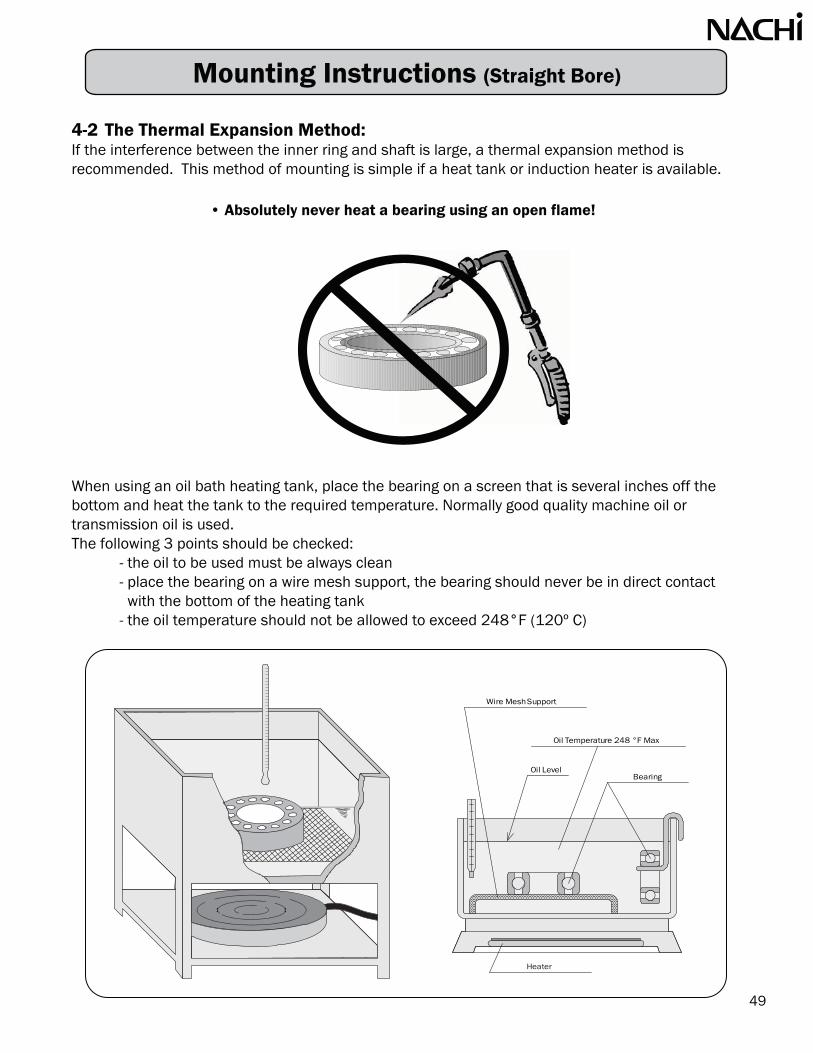
Mounting Instructions (Straight Bore)
4-2 The Thermal Expansion Method:If the interference between the inner ring and shaft is large, a thermal expansion method isrecommended. This method of mounting is simple if a heat tank or induction heater is available.
When using an oil bath heating tank, place the bearing on a screen that is several inches off the bottom and heat the tank to the required temperature. Normally good quality machine oil or transmission oil is used.The following 3 points should be checked:
- the oil to be used must be always clean- place the bearing on a wire mesh support, the bearing should never be in direct contactwith the bottom of the heating tank
- the oil temperature should not be allowed to exceed 248°F (120º C)
• Absolutely never heat a bearing using an open flame!
tnelaC a d o r
Oil Temperature 248 °F Max
BearingOil Level
Wire Mesh Support
Heater
49

If you frequently mount bearings of similar sizes, use an induction heater with automatic demagnetization. This tool heats by inducing electric currents. It takes only a short time to heat abearing to 248º F (120º C), even a large bearing.
The bearing should be mounted immediately after heating. If the bearing does not slip on smoothlydo not force it. In this case remove the bearing and reheat it. If expanding the bearing by heating isnot sufficient to get it on the shaft, you may also cool the shaft with dry ice to make it contract. Contraction also will occur in the axial direction as it is cooled and there is a possibility of some clearance developing between the inner ring and shoulder.To prevent this from happening, a small amount of pressure can be applied with a mounting dolly.
4-3 The Adapter or Withdrawal Sleeve MethodPlease refer to page 41 for extensive guidelines on proper mounting procedures for this method.(Assembly Instructions for Spherical Roller Bearing)
5. LubricationLubricants are indispensable for all bearings and are classified into oils and greases. Make sure thata specified and adequate amount of clean lubricant is used. When using oil as a lubricant withhorizontal shafts, the static oil level must be approx. at the center of the ball or roller at the bottomof its travel. In case of vertical shafts, the oil level is set slightly above the center line of the bearing.The volume of grease to be injected is about 1/3 or 1/2 of the total volume of the internal bearingspace. The volume of grease is reduced slightly if the bearing runs at high speeds. In NACHI sealedor shielded bearings the appropriate amount of grease is supplied.Do not subject the sealed or shielded bearings undo pressure. This may cause a deformation of sealor shield resulting in bearing problems. No attempt should be made to add lubricant to thesebearings. Attempting to do so will most likely result in damage to the bearing.
6. Test Running the EquipmentIf possible, do not run bearings at the full operating speed immediately installation. First, rotate theshaft manually and then run the machine at slow speeds. Make sure that the bearings run smoothlyand that there is no abnormal noise or vibration. If no problem is detected, gradually raise the speedwatching the temperature and checking the lubricant.
50
Mounting Instructions (Straight Bore)

Mounting Instructions (Tapered Bore)
Tapered-bore spherical roller bearings can be mounted either on a tapered shaft or on a cylindrical shaft using a tapered adapter sleeve.
Note: Leave the bearing in its protective wrapping until ready to assemble it on the shaft.Do not wash off the preservative coating: it protects the bearing and is compatible with all standard lubricants. Gather all necessary parts and tools before starting.Required Tools and Equipments:
• Micrometer • Lockwasher • Adapter Sleeve; if required• Feeler Gauge • Hammer & Rod • Graphite or Molybdenum Paste• Spanner Wrench • Locknut • Light-duty Oil
1. Measure Shaft DiameterCheck the shaft for dimensional accuracy with a micrometer, also check for nicks and burrs. If any discrepancies are found on the shaft, have it reworked to conform to specification.
A B
12
3
4
51
Inchmm Inch
Over Incl Over Inclmm
30
50
80
120
180
250
315
50
80
120
180
250
315
400
1.1811
1.9685
3.1496
4.7244
7.0866
9.8425
12.4016
1.9685
3.1496
4.7244
7.0866
9.8425
12.4016
15.748
+0.000-0.062
+0.000-0.074
+0.000-0.087
+0.000-0.100
+0.000-0.115
+0.000-0.130
+0.000-0.140
+0.0000-0.0025
+0.0000-0.0030
+0.0000-0.0035
+0.0000-0.0040
+0.0000-0.0045
+0.0000-0.0050
+0.0000-0.0055
Nominal Shaft Diameter Deviation
Shaft Tolerances When Used with Adapter or Withdrawal Sleeves
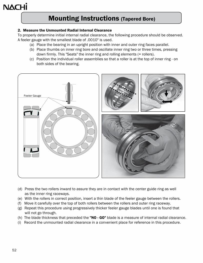
2. Measure the Unmounted Radial Internal ClearanceTo properly determine initial internal radial clearance, the following procedure should be observed.A feeler gauge with the smallest blade of .0010" is used.
(a) Place the bearing in an upright position with inner and outer ring faces parallel.(b) Place thumbs on inner ring bore and oscillate inner ring two or three times, pressing
down firmly. This "Seats" the inner ring and rolling elements (= rollers).(c) Position the individual roller assemblies so that a roller is at the top of inner ring - on
both sides of the bearing.
(d) Press the two rollers inward to assure they are in contact with the center guide ring as wellas the inner ring raceways.
(e) With the rollers in correct position, insert a thin blade of the feeler gauge between the rollers.(f) Move it carefully over the top of both rollers between the rollers and outer ring raceway.(g) Repeat this procedure using progressively thicker feeler gauge blades until one is found that
will not go through.(h) The blade thickness that preceded the "NO - GO" blade is a measure of internal radial clearance.(i) Record the unmounted radial clearance in a convenient place for reference in this procedure.
Feeler Gauge
52
Mounting Instructions (Tapered Bore)

Mounting Instructions (Tapered Bore)
3. Mount the Adapter Sleeve, if RequiredIf the bearing is to be mounted on a tapered shaft, skip this step. Either dimensionally or visuallydetermine the final position of the bearing. Slide the adapter sleeve onto the shaft with the threadson the sleeve facing outboard side. Position the sleeve at the approximate location of the bearingcenterline.
(a) remove oil from the shaft to prevent transfer of oil to the bore of the adapter sleeve.(b) for SAF units slide inner triple seal onto shaft. This seal slides freely into position.(c) position adapter sleeve onto shaft with threads to outboard.
4. Mount the BearingApply a light coating of oil on the outside diameter of the sleeve to facilitate bearing mounting.Starting with the large end of the bearing bore, slide the bearing on the adapter sleeve or shaft sothat the taper of the bearing matches the taper of the adapter or shaft. With the bearing hand tighton the adapter sleeve or shaft, position the bearing in the correct location on the shaft. Please note,as the bearing is pushed up the adapter the position of the bearing will move about 1/8”.
over incl. min max min max min max
Radial Clearance Prior to Mounting (in)Bearing BoreDiameter (mm) Normal C3 C4
53
3040506580
100120140160180200225250280
40506580
100120140160180200225250280315
0.00140.00180.00220.00280.00320.00390.00470.00510.00550.00630.00710.00790.00870.0095
0.00200.00240.00300.00370.00430.00530.00630.00710.00790.00870.00980.01060.01180.0130
0.00200.00240.00300.00370.00430.00530.00630.00710.00790.00870.00980.01060.01180.0130
0.00260.00320.00370.00470.00550.00670.00790.00910.01020.01140.01260.01380.01540.0169
0.00260.00320.00370.00470.00550.00670.00790.00910.01020.01140.01260.01380.01540.0169
0.00340.00390.00470.00590.00710.00870.01020.01180.01340.01460.01610.01770.01930.0213

5. Drive Up the BearingA coating of graphite or molybdenum disulfide paste on bothfaces of the lock washer and adapter threads will reducethe mounting forces during assembly. Slip the lock nuton the adapter, the ID tang locates in the split of theadapter under the bearing. Position the locknut on thethreads of the adapter with the adapter with thechamfered face toward the bearing. Tighten the locknutwith a heavy-duty spanner wrench. If using a hammer andchisel, be careful not to damage the lock washer or add debrisinto the bearing. Periodically check the internal radial clearance.When the required reduction in radial clearance is measured advance the locknut to the align upthe locknut to the closest lock washer tang and bend the tang over into the slot to secure thelocknut from backing off.
Reduction of Radial Clearance
FORCE
over incl. Target min max min max Normal C3 C4
3040506580
100120140160180200225250280
Bearing BoreDiameter (mm)
Reduction in Internal RadialClearance (in)
Axial Displacement
1:12 taper (in)
Smallest Radial Clearanceafter Mounting (in)
54
40506580
100120140160180200225250280315
0.00100.00100.00150.00150.00200.00250.00300.00350.00400.00450.00500.00500.00550.0060
0.00080.00100.00120.00160.00180.00200.00260.00300.00310.00350.00390.00430.00470.0051
0.00100.00120.00160.00200.00240.00280.00350.00390.00430.00510.00550.00590.00670.0075
0.01400.01800.02000.02800.03000.03100.04700.05100.05500.05900.06700.07100.07900.0870
0.01800.02000.02800.03300.03900.04700.05900.06700.07500.08700.09400.10200.11400.1260
0.00060.00080.00100.00100.00140.00200.00220.00220.00240.00280.00310.00350.00390.0043
0.00100.00120.00140.00160.00200.00260.00310.00350.00390.00390.00470.00510.00550.0059
0.00160.00200.00220.00280.00310.00390.00430.00510.00590.00630.00710.00790.00870.0094
Mounting Instructions (Tapered Bore)

Shaft and Housing DimensionsMany times, the shaft selection is decided by the customer on the basic design. Shaft strength is normally one of the primary limitations. Bearing size is then determined by the size of the customershaft. Housing size normally has more flexibility. The outside diameter of the bearing and the widthof the bearing can be dictated by our customers, but these dimensions are normally open to discussion. As previously shown, bearings with the same bore and OD dimension haveconsiderable variations.
Please review the section on Shaft and Housing Fitting Practices. These are straight forward. Thechart for shaft fits requires the product type, the shaft size, the application type and the loadingconditions. The chart produces a tolerance class which is a small case letter followed by a number. Using the shaft size and tolerance class a second set of charts show the bearing bore tolerance and the recommended shaft tolerance. We use these shaft to bearing fits to determine bearing internal clearance removal.
The chart for housing fits is similar to the shaft chart, as knowing the bearing type, application andloading conditions, we are able to, again, find a tolerance class for the housing. The tolerance classfor the housing wil be a capital letter followed by a number. Using the bearing OD and the tolerance class, a second set of charts shows the bearing OD tolerance and the recommended housing bore tolerance. We use these housing to bearing fits to determine bearing internal clearance removal.
Internal ClearancesInterference fits between the shaft & bearing and housing & bearing reduce the bearing internal clearance. This calculation is dependent on operating temperature, housing material, housingcross section, shaft material, and solid or hollow shaft. This calculation can be done manually or on our website at www.nachiamerica.com.
Environmental ConditionsMost of the time, we are considering open bearings or bearings without seals. Discussions on housing seals are important as contamination leads to bearing failure by lubrication. Redundant sealing or seals with dual acting features are always an important point. Lubricant is normally selected by thecustomer so we will comment on our experiences with the specific products.
We always try to use standard commercial parts as the cost of special bearings will increase thecost of the product as well as extend the availability of the bearings.
55
Bearing Selection

Material will expand when exposed to heat. We have to select the correct shaft toleranceand housing tolerance to ensure the material's Thermal Expansion Growth does notadversely affect the bearings.
Fixed vs. Expansion SidesTwo bearings are normally mounted on each shaft. One of the bearings will be designated as thefixed bearing as it axially locates the shaft with the housing. The second bearing will be theexpansion bearing. The expansion bearing may be similar to the NU cylindrical roller bearing andwill not accept thrust loading. The expansion bearing may be standard and the housing will bemachined so that the bearing will not be located up against a confining shoulder in the housing.Bearings are very stiff. As the bearing and shaft heat up we try and limit the possibility of thebearings loading axially against each other, as this is another possible way of causing prematurebearing failure.
Not Good
Good
Loose Fit Housing
Tight Fit Housing
Tight Fit Shaft
Now the Bearing is damagedby incorrect selection ofDimensional Tolerance
56
Bearing Selection

Bearing SelectionThe bearing application will determine which bearing would be the better selection. These are some of thebasic requirements for any application:
• Bearing Speed• Bearing Loads• Expected Service Life• Environmental Temperature• Contamination from Environment
• Seals for Housing and/or Bearing• Dimensional Limitations• Shaft and Housing Fits• Fixed vs Expansion• Lubrication
When reviewing the application please take time to write down these requirements. These application requirements are used to determine if the bearing is suitable for the application and the resultant life of the bearing.
Using the NACHI Catalog, select a bearing with a Dynamic Load Capacity larger than the load applied onthe bearing. Ensure the limiting speed is also greater than the fastest RPM at which the bearing will operate.
57
The "C" Capacity of the bearing is used to calculate bearing life. The loading ratio "load/C" indicates type of load. 1% to 8% are light loads, 8% to 18% medium loads; heavy loads are 18% to 25%, Light loaded applications tend to operate at higher speeds, medium loaded applications operate at half of the speed limit of the bearings, and heavy loaded applications operate at low RPM.
If possible, adjust the bearing selection until the L equals or exceeds expected service life. The expected service life indicates how long the user believes the bearing should last.
10
Design Life Recommendations:In order to determine what is acceptable life, the following guide is used by most manufacturers when designing their equipment:
Class of Machine L Hours ofService
10
Domestic Machines, Agricultural Machines, Instruments, Technical Apparatusor Medical Use
Machines Used For Short Periods Or Intermittently: Electric Hand Tools,Lifting Tackle In Workshops, Small Construction Machines
Machines Working Intermittently With High Reliability: Hoists, WorkshopCranes, Auxiliary Machinery In Power Stations, Domestic RefrigeratingAppliances, And Infrequently Used Machine Tools
Machines Used 8 Hours Per Day, But Not Always Fully Utilized: GeneralPurpose Gear Drives, Electric Motors
Machines Used 8 Hours Per Day And Fully Utilized: Machine Tools, WoodProcessing Machinery, Machines For The Engineering Industry, Cranes ForBulk Materials, Ventilating Fans, Conveyors, Printing Equipment, Centerfuges
Machines For Continuous Use, 24 Hours Per Day: Rolling Mill Gear Drives,Compressors, Pumps Mine Hoists, Stationary Electric Machines, Textile Machinery
Water Works Machinery Rotary Furnaces, Cable Stranding Machines,Propulsion Machinery For Ocean-Going Vessels
Pulp And Papermaking Machinery, Large Electric Motors, Power StationPlants, Mine Pumps And Ventilating Fans
300 to 3,000
3,000 to 8,000
8,000 to 12,000
10,000 to 25,000
20,000 to 30,000
40,000 to 50,000
60,000 to 100,000
Greater than 100,000

58
If a static or non-rotating load results in a contact stress that exceeds 4200 MPa, the elastic deformation limit is exceeded. The material surfaces yield and enters the “plastic deformation” zone. The deformation becomes a permanent dent called a “Brinell”. The load which will permanently damage the bearing is the “Co” value. Both "C" and "Co" values are in the catalog.
Exceeded Elastic Deformation
As the stress cycles increase and the fatigue limits are reached sub- surface fracturing begins. These fracture points are the origins of subsurface flaking.
The physical evidence of this subsurface flaking appears as a spall, which is a small fragment or chip removed from the raceway. This single spall will continue to grow in size similar to the way a pot-hole will develop in a road and continue to grow. Ultimately, spalling will end the life of a bearing. The quantification of this life- ending process is called "rolling fatigue life.” It is represented by the number of revolutions endured.
The bearing may be operable for some time beyond this point, but will be noisier and will eventually lock-up completely.
Subsurface Flaking
INCR
EASING
STRESS CYCLES
L 10 = Rating Fatigue Life in HoursC = Cataloged Basic Dynamic Load CapacityP = Equivalent Applied Load to the BearingN = Rotating Speed in RPMp = calculation exponent
- use 3 for ball bearings
- use 10/3 for roller bearings
In addition to C values for each bearing we have Co values. Co values are calculated values to determine the static load which will permanently damage the bearing by exceeding the elastic deformation.
Now let’s look under the surface and see how a ball interacts with the racewayunder this same load. At the loaded point of contact we can see that theball and raceway are actually deformed. However, the deformation incurredwill not be permanent. This process where the bearing steel will return toits original form is called “elastic deformation”.
L10
C
P
p106
60 N
Elastic Deformation
••
The following standard formula has been used for decades to estimate bearing life:
Bearing Selection

Bearing Selection
59
Information from the charts below is used to compare different bearing types and series and theirperformance characteristics.
0
50000
100000
150000
200000
250000
Dynamic Load Capacity (N)
0
1000
2000
3000
4000
5000
6000
7000
8000
9000
Grease RPM)
PairPair
PairPair

60
Bearing Selection
Life Calculation Example 1:
Bearing: 6210
Operating Load = 5,000 N Operating Speed = 1,000 rpm
Life Calculation Example 2:
Bearing: 6310
Operating Load = 5,000 N Operating Speed = 1,000 rpm
L =10 CP p 1060(N)6
L =10 3 1,000,00060(1000)35,0005,000L = (7) (16.66)10 3L = 5,714 Hours10
L =10 CP p 1060(N)6
L =10 3 1,000,00060(1000)62,0005,000L = (12.4) (16.66)10 3L = 31,764 Hours10

Bearing Selection
Load Comparison:Customers always want to know how much load will a bearing accept. The answer to this questionis complicated. To determine the load on the bearing the RPM and the expected life must be known. The first of the following two tables shows a comparison of Radial Ball Bearing's Radial Loading given the life requirement of 20,000 hours and 40,000 hours and speed requirement.All of the bearings are grouped by bore size. This chart shows the smaller the bearing cross sectionthe less load that bearing can accept. It also shows why the 6300 series bearings are called heavy duty.
The two tables show similar comparisons. The table below is grouped by bore size and showsradial ball bearing loads for various rpm and life requirements. On the next page the table showsball and roller bearing loads for the same rpm and life requirements.
Basic LoadBearing Rating (lbs) @900 rpm @1200 rpm @1800 rpm @3600 rpm
6805 967 94 86 75 59 75 68 59 476905 1574 153 139 122 97 122 111 97 776005 2271 221 201 176 139 176 160 139 1116205 3147 307 279 243 193 243 221 193 1536305 5306 517 470 410 326 410 373 326 2596810 1439 140 127 111 88 111 101 88 706910 3260 318 289 252 200 252 229 200 1596010 4901 478 434 379 301 379 344 301 2396210 7869 767 697 609 483 609 553 483 3836310 13939 1359 1234 1078 856 1078 980 856 6796815 2810 274 249 217 173 217 198 173 1376915 4676 456 414 362 287 362 329 287 2286015 8880 866 786 687 545 687 624 545 4336215 14838 1446 1314 1148 911 1148 1043 911 7236315 25405 2476 2250 1965 1560 1965 1786 1560 12386820 4406 429 390 341 271 341 310 271 2156920 9555 931 846 739 587 739 672 587 4666020 13489 1315 1195 1044 828 1044 948 828 6576220 27428 2673 2429 2122 1684 2122 1928 1684 13376320 38894 3791 3444 3009 2388 3009 2734 2388 18956830 10679 1041 946 826 656 826 751 656 5206930 19222 1874 1702 1487 1180 1487 1351 1180 9376030 28327 2761 2509 2191 1739 2191 1991 1739 13806230 39568 3857 3504 3061 2430 3061 2781 2430 19286330 61601 6004 5455 4765 3782 4765 4330 3782 3002
3 year life (20000 hrs.) 5 years life (40000 hrs.)
61
Applied Load (lbf)
@900 rpm @1200 rpm @1800 rpm @3600 rpm

Equivalent Dynamic Load:In the previous example, we mentioned “Equivalent Dynamic Load” Sometimes the load fluctuates and wemust average it into a steady equivalent dynamic load, or sometimes we have both radial loads and thrustloads and we must combine them into an equivalent radial load to use in the life calculation. To obtain the equivalent dynamic load “P”, we combine the radial forces “Fr” with the axial forces “Fa” using loading factors. These factors are selected dependent upon their ratio relative to one another and the contact angle and internal geometry of the bearing. The formula to combine this is as follows:
The selection of “X” and “Y” is usually more cumbersome than the life calculation itself. This has beengreatly simplified through the use of bearing manufacturers electronic catalogs that are available online.These electronic versions automatically select the proper loading factors.
Basic LoadBearing Rating (lbs) @900 rpm @1200 rpm @1800 rpm @3600 rpm @900 rpm @1200 rpm @1800 rpm @3600 rpm
6205 3147 307 279 243 193 243 221 193 1537205 2293 224 203 177 141 177 161 141 1125205 4901 478 434 379 301 379 344 301 239
NU205 3979 490 449 398 323 398 365 323 262NU205E 6587 810 743 658 535 658 604 535 434E30205J 7082 871 799 708 575 708 649 575 46722205EX 14164 1742 1598 1415 1150 1415 1298 1150 934
6210 7869 767 697 609 483 609 553 483 3837210 7082 690 627 548 435 548 498 435 3455210 12253 1194 1085 948 752 948 861 752 597
NU210 10791 1328 1218 1078 876 1078 989 876 711NU210E 15513 1908 1751 1550 1259 1550 1422 1259 1023E30210J 17199 2116 1941 1719 1396 1719 1576 1396 113422210EX 31924 3927 3603 3190 2591 3190 2926 2591 2105
6215 14838 1446 1314 1148 911 1148 1043 911 7237215 15400 1501 1364 1191 946 1191 1082 946 7515215 21583 2104 1911 1670 1325 1670 1517 1325 1052
NU215 21695 2669 2448 2168 1761 2168 1989 1761 1430NU215E 29227 3595 3298 2920 2372 2920 2679 2372 1927E30215J 31924 3927 3603 3190 2591 3190 2926 2591 210522215EX 59577 7329 6723 5953 4835 5953 5461 4835 3928
6220 27428 2673 2429 2122 1684 2122 1928 1684 13377220 28327 2761 2509 2191 1739 2191 1991 1739 13805220 37770 3681 3345 2922 2319 2922 2655 2319 1841
NU220 41142 5061 4643 4111 3339 4111 3771 3339 2712NU220E 56205 6914 6343 5616 4562 5616 5152 4562 3705E30220J 58004 7136 6546 5796 4708 5796 5317 4708 382422220EX 116906 14382 13193 11682 9488 11682 10716 9488 7707
6230 39568 3857 3504 3061 2430 3061 2781 2430 19287230 62950 6136 5574 4870 3865 4870 4424 3865 3068
NU230 84308 10371 9514 8424 6843 8424 7728 6843 5558NU230E 101169 12446 11417 10109 8211 10109 9273 8211 6670E30230J 104766 12888 11823 10469 8503 10469 9603 8503 690722230EX 269784 33189 30444 26958 21896 26958 24729 21896 17785
3 year life (20000 hrs.) 5 years life (40000 hrs.)
P = X • Fr + Y • Fa
62
Applied Load (lbf)
Bearing Selection

Bearing Selection
63
Basic LoadBearing Rating (lbs) @900 rpm @1200 rpm @1800 rpm @3600 rpm @900 rpm @1200 rpm @1800 rpm @3600 rpm7204 2990 673 612 534 424 534 486 424 3377205 3147 709 644 562 446 562 511 446 3547206 4362 982 892 779 619 779 708 619 4917207 5755 1296 1177 1029 816 1029 934 816 6487208 6879 1549 1407 1229 976 1229 1117 976 7747209 7711 1736 1578 1378 1094 1378 1252 1094 8687210 8026 1807 1642 1434 1138 1434 1303 1138 9047211 9915 2232 2028 1772 1406 1772 1610 1406 11167212 12005 2703 2456 2145 1703 2145 1949 1703 13527213 13692 3083 2801 2447 1942 2447 2223 1942 15417214 14209 3199 2907 2539 2015 2539 2307 2015 16007215 16120 3630 3298 2881 2286 2881 2617 2286 18157216 17334 3903 3546 3098 2459 3098 2814 2459 19517217 20054 4515 4102 3584 2844 3584 3256 2844 22587218 22932 5163 4691 4098 3253 4098 3723 3253 25827219 24955 5619 5105 4460 3540 4460 4052 3540 28097220 27878 6277 5703 4982 3954 4982 4526 3954 31387221 30351 6834 6209 5424 4305 5424 4928 4305 34177222 33049 7441 6761 5906 4688 5906 5366 4688 37217224 35522 7998 7267 6348 5038 6348 5768 5038 39997226 39793 8960 8141 7111 5644 7111 6461 5644 44807228 44290 9972 9060 7915 6282 7915 7191 6282 49867230 50585 11390 10348 9040 7175 9040 8213 7175 56957303 3103 699 635 554 440 554 504 440 3497304 3642 820 745 651 517 651 591 517 4107305 5148 1159 1053 920 730 920 836 730 5807306 6205 1397 1269 1109 880 1109 1008 880 6997307 7307 1645 1495 1306 1036 1306 1186 1036 8237308 8925 2010 1826 1595 1266 1595 1449 1266 10057309 11376 2561 2327 2033 1614 2033 1847 1614 12817310 14478 3260 2962 2587 2054 2587 2351 2054 16307311 16704 3761 3417 2985 2369 2985 2712 2369 18817312 19087 4298 3905 3411 2707 3411 3099 2707 21497313 21605 4865 4420 3861 3065 3861 3508 3065 24327314 24281 5467 4967 4339 3444 4339 3942 3444 27347315 26529 5973 5427 4741 3763 4741 4307 3763 29877316 28552 6429 5841 5103 4050 5103 4636 4050 32147317 30800 6935 6301 5504 4369 5504 5001 4369 34687318 33273 7492 6807 5946 4720 5946 5403 4720 37467319 35522 7998 7267 6348 5038 6348 5768 5038 39997320 37770 8504 7727 6750 5357 6750 6133 5357 42527321 42941 9669 8784 7674 6091 7674 6972 6091 48347322 47887 10782 9796 8558 6792 8558 7775 6792 5391
1 year life (8760 hrs.) 2 years life (17520 hrs.)
40º Angular Contact Ball BearingContinuous Thrust Loads (lbs.)Single Set
Applied Load (lbf)

Basic LoadBearing Rating (lbs) @900 rpm @1200 rpm @1800 rpm @3600 rpm @900 rpm @1200 rpm @1800 rpm @3600 rpm
1 year life (8760 hrs.) 2 years life (17520 hrs.)
Bearing Selection
40º Angular Contact Ball BearingContinuous Thrust Loads (lbs.)Duplex Set
64
7204 4857 1094 994 868 689 868 789 689 5477205 5113 1151 1046 914 725 914 830 725 5767206 7085 1595 1449 1266 1005 1266 1150 1005 7987207 9350 2105 1913 1671 1326 1671 1518 1326 10537208 11176 2516 2286 1997 1585 1997 1815 1585 12587209 12527 2821 2563 2239 1777 2239 2034 1777 14107210 13038 2936 2667 2330 1849 2330 2117 1849 14687211 16106 3626 3295 2878 2285 2878 2615 2285 18137212 19503 4391 3990 3485 2766 3485 3167 2766 2196
7213 22242 5008 4550 3975 3155 3975 3611 3155 25047214 23082 5197 4722 4125 3274 4125 3748 3274 25997215 26186 5896 5357 4680 3714 4680 4252 3714 2948
7216 28159 6340 5760 5032 3994 5032 4572 3994 31707217 32578 7335 6664 5822 4621 5822 5290 4621 36687218 37253 8388 7621 6657 5284 6657 6049 5284 4194
7219 40540 9128 8293 7245 5750 7245 6582 5750 45647220 45287 10197 9265 8093 6424 8093 7353 6424 50987221 49305 11102 10086 8811 6994 8811 8006 6994 55517222 53688 12088 10983 9595 7615 9595 8717 7615 60447224 57705 12993 11805 10312 8185 10312 9369 8185 64967226 64644 14555 13224 11553 9169 11553 10496 9169 72787228 71949 16200 14719 12858 10205 12858 11682 10205 81007230 82175 18503 16811 14685 11656 14685 13343 11656 92517303 5040 1135 1031 901 715 901 818 715 5677304 5917 1332 1210 1057 839 1057 961 839 6667305 8364 1883 1711 1495 1186 1495 1358 1186 9427306 10080 2270 2062 1801 1430 1801 1637 1430 11357307 11870 2673 2428 2121 1684 2121 1927 1684 13367308 14499 3265 2966 2591 2057 2591 2354 2057 16327309 18480 4161 3781 3303 2621 3303 3001 2621 20817310 23520 5296 4812 4203 3336 4203 3819 3336 26487311 27136 6110 5551 4849 3849 4849 4406 3849 30557312 31007 6982 6343 5541 4398 5541 5035 4398 34917313 35098 7903 7180 6272 4978 6272 5699 4978 39517314 39444 8881 8069 7049 5595 7049 6404 5595 44417315 43096 9704 8816 7702 6113 7702 6997 6113 48527316 46383 10444 9489 8289 6579 8289 7531 6579 52227317 50035 11266 10236 8942 7097 8942 8124 7097 56337318 54053 12171 11058 9660 7667 9660 8776 7667 60857319 57705 12993 11805 10312 8185 10312 9369 8185 64967320 61357 13815 12552 10965 8703 10965 9963 8703 69087321 69757 15707 14270 12466 9895 12466 11326 9895 78537322 77792 17516 15914 13902 11034 13902 12631 11034 8758
Applied Load (lbf)

“AC” = 25º contact angle
Machine Tool Bearings
The contact angle is the angle formed by a line drawnbetween the points of contact of the balls with theraceways and a plane perpendicular to the bearingaxis. The contact angle influences the axial and radialcharacteristics of a bearing.
“C” = 15º contact angle
“B” = 40º contact angle
Contact angles of TAB bearings are 60°
NACHI Super Precision Angular Contact Ball Bearings
Super Precision Bearings are bearings with ISO Class 5 or higher tolerance.
The tolerance of bearings, dimensional and running accuracy, is classified intofive classes by the International Standardization Organization and other standards as shown in the table below:
NoteNormal Class 6 Class 5 Class 4 Class 2 InternationalClass 0 Class 6 Class 5 Class 4 Class 2 JapaneseABEC 1 ABEC 3 ABEC 5 ABEC 7 ABEC 9 AmericanRBEC 1 RBEC 3 RBEC 5 - - American
0 P6 P5 P4 P2 German
Super Precision BearingsPrecision BearingsISO 492JIS B 1514
ANSI/ABMA 20
DIN 620
Point ofcontact
Contactangle
Contact Angle
65
CY Series (15° contact angle) 7000CY ~ 7020CY 7200CY ~ 7220CY
ACY Series (25° contact angle) Nylon or Phenolic cage Ceramic optional
BNH Series (High Speed Type) BNH907C ~ BNH932C BNH007C ~ BNH032C
TAB Series (Ball Screw Support Bearings) 15TAB04 ~ 60TAB12
“A” = 30º contact angle
Ceramic optional 7000 series boundary dimensions
Seals optional

BackThe thick face of the outer ring is the Back side. The thick face is the side receiving the load.
FaceThe thin face of the outer ring is the Face side. The face side is at times called the front side.
Counter Bore:Removing the shoulder of the ring of a ballbearing and replacing with a chamfer.
Appearance indicates an angular ballbearing, not a radial ball bearing.
Permits better lubrication flow.Ring is no longer a symmetrical part.
Angular Contact Bearings have Two Sides
The Bearings are Not Interchangeable.
Counter Bore
66
contact angle is used for high speed and light load applications.s and heavy axial load applications.
The following may occur when using a "C" contact angle instead of a “B” contact angle.
• Poor Rigidity in Axial Direction• High Operating Temperature• Short Service Life
FACE
Load
Load
BACK
CounterBore
Machine Tool Bearings

Machine Tool Bearings
Back-to-Back Mounting (DB)In this arrangement the contact angles diverge so that the effective distance between bearing center is increased. Axial and radial loads can be used in any direction. This arrangement accomodates radial stiffness and resistance to moment loads.
These are the suffixes for the bearing arrangements.
Face-to-Face Mounting (DF)In this arrangement the contact angles converge so that the effective distance between bearing center is decreased. Axial and radial loads can be used in any direction. This arrangement has less radial stiffness and is generally used where precise alignment cannot be achieved.
Tandem Mounting (DT)In this arrangement the contact angles are parallel. Axial loads are shared but can be applied in only one direction. Must be opposed by another bearing, or set of bearings, to accommodate the axial load in the reverse direction.
Configured bearings can only be used in one arrangementFor DB bearings, the preload is only controlled on the “Back” side of the bearings.For DF bearings, the preload is only controlled on the “Face” side of the bearings.If a DF arrangement is made from DB set, we cannot expect the correct preload.
67

BARDEN
DBT
(DFT)
DBD
DBTT
(DFTT)
(DFD)
KOYO
DBD
DFD
DTD
DBB
(DFF)
RHP
2TB
2TF
3T
3TB
2TB2T (QB)
2TF2T(QF)
3TF
4T
NTN
DBT
DFT
DTT
DBTT
DTBT
DTFT
DFTT
DTTT
NSK
DBD
DFD
DTD
DBT
DBB
DFF
DFT
DTT
SKF
TBT
TFT
TT
QBT
QBC
QFC
QFT
QT
NACHI
FFB
BFF
FFF
FFFB
FFBB
BBFF
BFFF
FFFF
Angle
//\
\//
///
///\
//\\
\\//
\///
////
TD FD BD
68
These sets of two bearings have been selected as matched pairs at the factory. One DU set of bearings has only a small dimensional variation (2 m maximum) on the bore diameter and OD of the two bearings. The dimensions are shown on the inspection sheet in the box and on the side of the box. Each bearing is serialized.
To make triplex and quadruplex combinations, DU sets with similar Bore and OD dimensions should be selected. The selected sets should have no more than 2 m (0.002 mm) variation between the bearings on bore size and OD size. This practice ensures the preload will be correct and that there will be proper load sharing across each bearing.
Most manufacturers have the same nomenclature for DU, DB, DF and DT.
Each manufacturer has their own suffixes for Triplex and Quad arrangements. Common suffixes are shown below.
“DU” is the suffix for a duplex universal combination bearing set. We call these universal bearings “Flush Ground Bearings”.
For DU bearings, the preload gap (width dimension) of both the “Face” and “Back” sides is controlled to get a proper preload. Any arrangement, DB, DF, DT or other multi-combinations can be arranged.
Machine Tool Bearings

Machine Tool Bearings
Preload means to apply a permanent axial load to a bearing.All of the internal bearing clearance is removed.
Preloading achieves a number of objectives:Elimination of free radial and axial movementReduced deflection from externally applied loads
Single row angular contact bearings can only be loaded in one direction.If the bearing is loaded in the wrong direction away from the back face, the bearing could:
• Disassemble• Have high operating noise• Fail quickly
Load
Load LoadLoad
69

BearingBore(mm)
72007000Clamping Force
70
On “DB” arrangements the inner ring must be clamped to preload the bearings.
On “DF” arrangements the outer ring must be clamped to preload the bearings.
1012151720
2530354045
5055606570
7580859095
100110120
550770770860
1000
13001400160018002000
22002700290031003300
35005100540087007600
790081008600
124173173194225
293315360405450
495608653698743
7881148121519581710
177818261935
600830830
11001200
14002200310028003600
38004000440060005700
610056008200
1000012000
110001300016000
135187187248270
315495698630810
855900990
13501283
13731260184522502700
247529253600
N lbs N lbs
Machine Tool Bearings

GE GL GM GH
Machine Tool Bearings
NACHI has four kinds of preload as shown in the table below.
GE = Extra Light GL = Light (std) GM = Medium GH = Heavy
Units : Newtons / lbs
BoreNumberGE GL GM GH
Light PreloadBrg. No
BNH007BNH008BNH009BNH010BNH011BNH012BNH013BNH014BNH015BNH016BNH017BNH018BNH019BNH020
Ball Screw Support BearingsHigh Speed Small Ball Series Medium Preload
71
205
5011
7016
10023
14533
19544
5011
10023
14533
19544
29566
39088
10023
19544
29566
39088
590133
785177
14533
29566
39088
590133
785177
1170263
1470331
00010203040506
07
080910111213141516
17181920
307
7016
10023
14533
19544
29566
7016
14533
19544
29566
39088
490110
14533
29566
490110
590133
785177
980221
19544
490110590133
785177
980221
1470331
1960441
N78.598.198.198.1147147147245245294294392392392
lbs1822222233333355556666888888
Brg. No
15TAB0417TAB0420TAB0425TAB0630TAB0635TAB0740TAB0740TAB0945TAB0745TAB1050TAB1055TAB1055TAB1260TAB12
N21602160216033303330392039205200412059806280628070607060
lbs486486486749749882882
1170927
13461413141315891589
7000 Preload 7200 Preload

"Medium preload" can be used in place of "Light preload". Please note:
• Higher preload makes the spindle more ridged.• Spindle rotating torque would increase.• Spindle would have higher operating temperature.
Variation in preloads may work or they may not depending uponthe customer expectation and usage of the equipment.
Preloads are similar for all manufacturers but not identical.
Manufacturing Comparison of Preload of Duplex Pair
NACHINSKNTN
KOYOFAG
NACHINSKNTN
KOYOFAG
NACHINSKNTN
KOYOFAG
NACHINSKNTN
KOYOFAG
7018C7012C7006C
72
Hea
vyM
ediu
mLi
ght
Extr
a Li
ght GE
C2GLS--
GLC7GNL
UL
GMC8GMM
UM
GHC9GHH
US
N50203025--
100100808095
200210150200300
390390300390580
lbs11576--
2323181821
4547344568
88886888
131
N10055
10065--
200275200200235
390590490490700
7851225980980
1350
lbs23122315--
4562454553
88133110110158
177276221221304
N200120150140
--
390640390440470
7851325890980
1422
14752750196019602940
lbs45273432--
881448899
106
177298200221320
332619441441662
Machine Tool Bearings
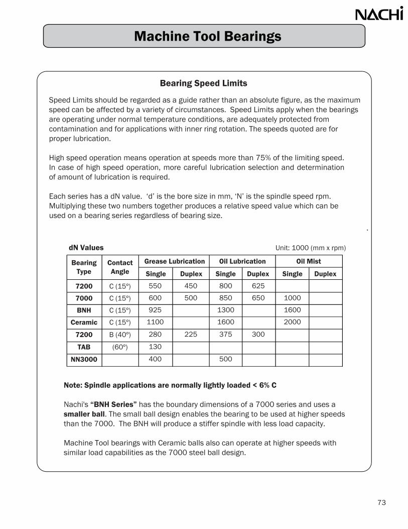
Bearing Speed Limits
Speed Limits should be regarded as a guide rather than an absolute figure, as the maximumspeed can be affected by a variety of circumstances. Speed Limits apply when the bearingsare operating under normal temperature conditions, are adequately protected fromcontamination and for applications with inner ring rotation. The speeds quoted are for proper lubrication.
High speed operation means operation at speeds more than 75% of the limiting speed.In case of high speed operation, more careful lubrication selection and determination of amount of lubrication is required.
Each series has a dN value. ‘d’ is the bore size in mm, ‘N’ is the spindle speed rpm.Multiplying these two numbers together produces a relative speed value which can beused on a bearing series regardless of bearing size.
Note: Spindle applications are normally lightly loaded < 6% C
Nachi's “BNH Series” has the boundary dimensions of a 7000 series and uses asmaller ball. The small ball design enables the bearing to be used at higher speedsthan the 7000. The BNH will produce a stiffer spindle with less load capacity.
Machine Tool bearings with Ceramic balls also can operate at higher speeds withsimilar load capabilities as the 7000 steel ball design.
dN Values Unit: 1000 (mm x rpm) Bearing
Type
7200
7000
BNH
Ceramic
7200
TAB
NN3000
ContactAngle
C (15º)
C (15º)
C (15º)
C (15º)
B (40º)
(60º)
Single Duplex Single Duplex Single Duplex
Oil MistOil LubricationGrease Lubrication
73
550
600
925
1100
280
130
400
450
500
225
800
850
1300
1600
375
500
625
650
300
1000
1600
2000
Machine Tool Bearings

(specific weight of grease 0.9 grams per cc.)
Common Machine Tool GreasesManufacturer GreaseKluberKluberKyodo Yushi
*Nachi recommends a 15% grease fill
Master Grease Amount Chartunits: cm3 & grams
Bore
(mm) cm 3 grams cm 3 grams cm3 grams cm3 grams cm3 grams
Conversion: 1 cm3
= 0.9 grams
7000C NN3000
74
10
12
15
1720
25
30
3540
45
5055
60
65
7075
80
85
90
95
100
105
110
120
130
140
150
160
170
180
190
200
0.14
0.15
0.21
0.260.44
0.51
0.72
0.961.17
1.53
1.612.39
2.55
2.73
4.164.31
4.82
5.45
7.38
7.95
8.27
0.12
0.14
0.19
0.230.39
0.46
0.65
0.861.05
1.38
1.442.15
2.30
2.46
3.743.87
4.33
4.90
6.64
7.16
7.44
0.18
0.26
0.33
0.450.71
0.80
1.23
1.551.95
2.31
2.793.89
4.98
5.87
6.787.41
8.85
11.0
14.0
17.5
20.3
0.16
0.23
0.30
0.410.63
0.72
1.11
1.391.76
2.08
2.513.50
4.48
5.28
6.106.67
7.97
9.92
12.57
15.77
18.27
0.841.08
1.35
1.462.10
2.25
2.40
3.303.45
4.50
4.65
6.00
6.30
6.45
8.10
9.90
10.7
16.2
17.1
20.7
26.1
34.1
0.760.97
1.22
1.311.89
2.03
2.16
2.973.11
4.05
4.19
5.40
5.67
5.81
7.29
8.91
9.59
14.58
15.39
18.63
23.49
30.65
0.54
0.89
1.131.43
1.92
2.072.94
3.11
3.27
4.564.94
6.95
7.17
9.44
9.68
10.1
13.8
17.1
19.0
26.6
29.3
35.2
43.2
56.1
76.2
79.5
103
0.49
0.80
1.011.28
1.73
1.862.65
2.79
2.94
4.104.44
6.25
6.45
8.49
8.71
9.09
12.39
15.42
17.06
23.96
26.35
31.68
38.92
50.48
68.55
71.56
92.27
1.71
2.16
2.72
6.30
6.90
8.55
1.51
1.94
2.44
5.67
6.21
7.70
NBU15LDS18Multemp PS2
7200C BNH TAB
Machine Tool Bearings

Machine Tool Bearings
Bore ( m) ( m)
- 8 0
Shaft & Housing Tolerance and Fitting Practice
Shaft(mm) (mm) Fit Brg. Shaft
Possible Resultant
Shaft over incl. Bore Seat ( m) ( m)( m) ( m)
10 18 h3 0 - 4 - 4 4L-4T 0 - 2T18 30 h3 0 - 5 - 4 0 - 2.5T30 50 h3 0 - 6 - 5 0 - 2.5T
T9-L4 4 - 7 - 03h0805T11-L5 5 - 8 - 03sj02108 0 - 4T
120 180 js3 - 10 6L-1 T 4+ 180 250 js3 - 12 7L-17T 0 - 6T10 18 h5 0 - 4 8L-4T 18 30 h5 0 - 5 9L-5T 30 50 h5 0 - 6 - 11 50 80 h5 0 - 7 - 13
Housing Fit Brg. HousingFixed End (mm) (mm) OD Bore ( m) ( m)
over incl ( m) ( m)K5
18 50 JS3 50 120 JS3
120 180 JS3 180 250 JS3
Ball Screw Brg. H6
Housing Fit Brg. HousingFree End (mm) (mm) OD
over incl ( m) ( m)K5 0 - 8 +2 - 13 10L-13T
18 50 H3 0 - 6 +7 - 0 13L-0T 10L - 6L50 120 H3 0 - 8 +8 - 0 16L-0T 13L - 8L
120 180 H3 0 - 10 +10 - 0 20L-0T 18L - 12L180 250 H3 0 - 11 +12 - 0 23L-0T 22L - 15L
Ball Screw Brg. H6 0 - 6 0 - 21 27L-0T
L = loose or slip fitT = tight or interference fit
All sizes
Ball Bearings
Shaft OD
Angular Contact
Tolerance
Angular Contact
Ball Screw
Angular Contact
Housing
Support Bearings
Bore
All sizes
Cylindrical
Tolerance
Housing Tolerance
All sizes
Ball Bearings
Ball Bearings
Bore
Cylindrical All sizes
75
Hgs.
00
000
+2+3
- 6+5 - 7
4L-5T5L-6T
0 - 5T
0 - 3T
- 9 000
11L-6T13L-7T
L - 0L - 0L - 0L - 0
- 8 0- 6 0- 8 0- 10 0- 11 0- 6 0
+2 - 13 +6 - 1 +7 - 1 +8 - 2
+9 - 3 0 - 21
10L-13T 12L-1T 15L-1T 18L-2T 20L-3T 27L-0T
03L - 04L - 05L - 06L - 0
L - L
Ideal Fit
0
Possible Resultant
Ideal Fit
Possible Resultant
Ideal Fit
L - L
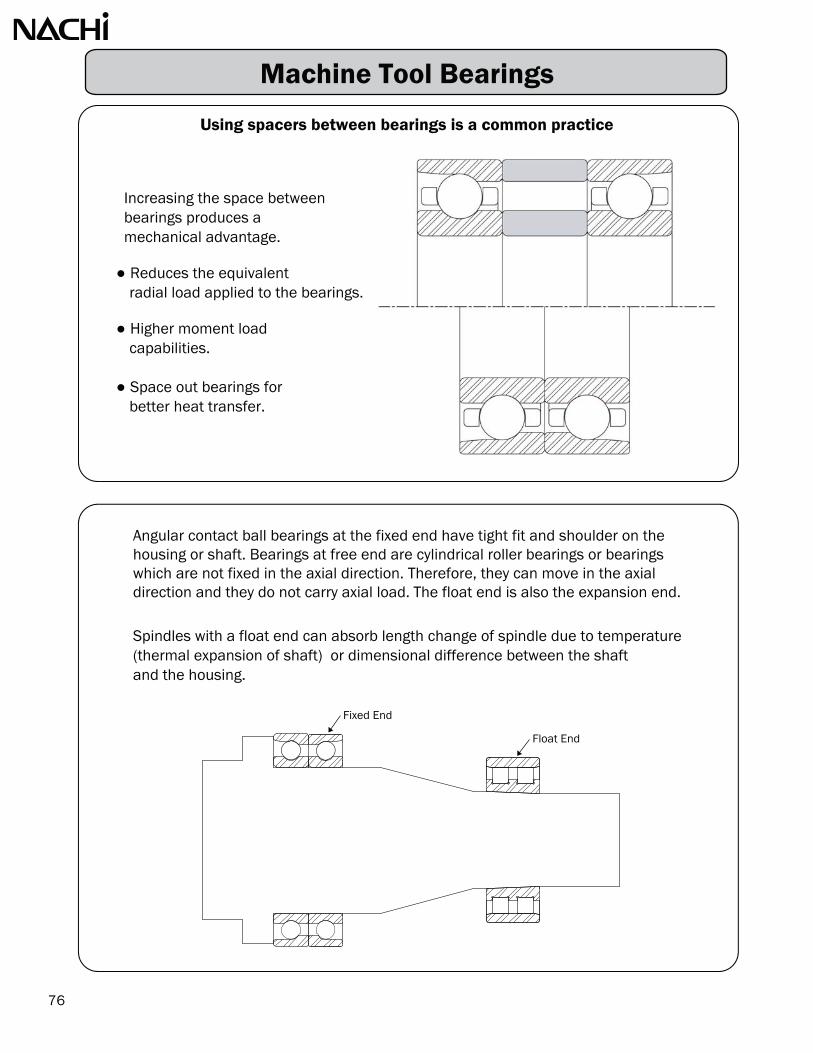
Using spacers between bearings is a common practice
Increasing the space betweenbearings produces amechanical advantage.
Reduces the equivalentradial load applied to the bearings.
Higher moment loadcapabilities.
Space out bearings forbetter heat transfer.
Angular contact ball bearings at the fixed end have tight fit and shoulder on the housing or shaft. Bearings at free end are cylindrical roller bearings or bearings which are not fixed in the axial direction. Therefore, they can move in the axial direction and they do not carry axial load. The float end is also the expansion end.
Spindles with a float end can absorb length change of spindle due to temperature (thermal expansion of shaft) or dimensional difference between the shaftand the housing.
76
Machine Tool Bearings
Fixed End
Float End

[cage view]
Hardened stamped steel cages on our EXQ-V design providesa great selection for applications with heavy vibration.
Extreme contaminated lubrication application are normallyhuge problems for bearings. Nachi has had great successon these applications by using heat treated steel cages.
Nachi has our own steel plant and our expertise in steelmaking has transferred to all of our products like bearings,drills, broaches, heat treatment equipment and tool steels.
HIGHEST LOAD CAPACITY Nachi’s EXQ-V spherical roller bearing design maintains the highest load capacities by utilizing the biggest rollers (longest length, largest diameter).
HARDENED CAGE Hardening steel cage increases the strength, making the cage more fatigue resistant. Nachi has been a leader in the main support bearing on the high speed trains in Japan. We have developed testing procedures which separate great products from good products. As shown by thetest results, we have a great design.
LOWER OPERATING TEMPERATURE In addition to increased strength, our hardened steel cage hasa lower coefficient of friction which generates less heat and promotes lower operating temperatures. Lower operating temperature will result in longer grease life.
Bearings for Vibrating Applications
77
Spherical Roller Bearing Design & Configuration
EXQ-V Series Features
EXQ-V DESIGN Nachi vibrating screen bearings have a standard bore tolerance and special OD tolerance that is the center 2/3 "P6". Increased internal clearance, that is the lower 2/3 of C4, ensures the bearings will have enough radial clearance when operating.
EXQ-V Special Fits
Vibrating Screen Bearings require special fit conditions to handle the centrifugal force of eccentric
loading. A "g5" loose fit is used on the shaft and an "N6" interference fit is used on the housing.

0
10
20
30
40
50
60
70
80
EXEXQ
-V #1 #2 #3
Shoc
k R
epet
ition
(10
4 tim
es)
Test conditions Vibrating cycles 119 cpm
Vibrating acceleration 200 GTemperature ambient
EX Nachi EXQ-V Nachi #1 VA405 #2 HPS #3 E1-T41A
Vibration Test
0
10
20
30
40
50
60
70
0 2000 4000 6000
(rpm)
()
22312EXQ-V (vibrating resistant)
22312EX (standard cage)
Speed / Temperature Test
78
Bearings for Vibrating Applications

Most Frequent Causes of Bearing Failures
The majority of premature bearing failures are caused by inadequate lubrication. Anti-friction rolling element bearings are designed to have a thin film of oil between the rolling elements and the raceway surfaces. When this film degrades or gets too thin the rolling elements contact the raceway surfaces and wear develops. Anti-friction bearings are not designed to be wear parts.
There are many causes for inadequate lubrication:1. Insufficient amount of grease (lubricant) or an excessive amount of grease.2. Using a lubricant with the wrong characteristics, or mixing of greases (lubricants).3. Moisture or hard particle contamination from the operating environment. Contamination
can degrade, wear the bearing surfaces, or degrade the oil film which will also cause wear.4. Excessive operating temperature from the environment or from the operating speed
of the bearing. The faster a bearing operates, the higher the temperature. Bearing andlubricants have temperature limits and speed limits.
Inadequate Lubrication 54%
Improper Sealing 25%
Overload or Excessive Speed 10%
Damage from Surrounding Parts 5%
Improper Mounting or Mishandling
5%
Manufacturing Defects 1%
79

Investigating bearing failure typically involves reviewing the application. The bearing racewaystend to leave the best clues as to what may have caused the bearing failure. First, the bearingswill have to be disassembled to view the ring raceways.
Since the most common cause for bearing failure is inadequate lubrication, we will use thischaracteristic to determine bearing failure. Frosting patterns on the inner ring and outer ring raceways is the first indication of inadequate lubrication. The raceway surfaces are startingto have contact with the rolling elements and these slight wear patterns develop.
Bearings are like fuses, something causes the bearing to fail. We use these visual wear patternsto determine if the application is normal or if something is abnormal. By shining a bright light(Mag flashlight) down the raceway, these patterns pop out and become more visible.
The most common application is the inner ring rotation with a radial load (upper left). By looking at the frosting patterns we can determine if the application is consistent or if something in the application is affecting the bearing. Orientation is always an important part of the investigation. Knowing which side of the bearing was positioned in or out will help in determining which way thebearing was loaded.
Inner Ring RotationMisalignment
Outer Ring RotationAxial Load & Misalignment
Inner Ring RotationHousing Bore is Oval
Inner Ring RotationNo Radial Internal Clearance
Inner Ring RotationRadial Load
Outer Ring RotationRadial Load
Inner or Outer Ring RotationAxial Load in One Direction
Inner Ring RotationCombined Radial & Axial Loads
80
Most Frequent Causes of Bearing Failures

Seizure: Bearing seized up from excessive heat. Discoloration, softeningand fusion of raceway and rolling element.
Causes: Poor lubrication, excessive load, excessive, clearance too small,entrance of contaminants, poor precision of the shaft or housing
Countermeasures: Reconfirm bearing selection, review lubricant selection type & quantity, check shaft & housing, improve sealing mechanism
Flaking: Repetitive Heavy stress cycle between the bearing raceways androlling elements resulting in surface fatigue cracks and spalls
Causes: Excessive load, poor mounting, excessive moment load, entry of contamination,improper bearing clearance, improper shaft & housing precision
Countermeasures: Reconfirm the bearing application & load conditions, improve mounting method,improve sealing mechanism, use proper lubricant, check shaft & housing
Cracks: Splits and cracks in the inner ring, outer ring or rolling element.Causes: Excessive interference fit, impact load, progression of flaking,
shaft corner larger than bearing, heat generation & fretting problemCountermeasures: Check fits, check shaft & housing, review the load conditions,
make shaft corner smaller than that of the bearing
81
Most Frequent Causes of Bearing Failures

Fracture: Cracked inner ring rib. Broken retainer.Causes: Excessive impact load during handling or mounting, heavy shock
load or vibrationCountermeasures: Review handling, check mounting practice
re-check load conditions & bearing selection
True Brinelling: The occurrence of dents on the raceways that are the result
of exceeding the elastic limit of the steel. Causes: Any static overload, severe impact
Countermeasures: Install bearings by applying force only to the ring being press fitted,recheck static load conditions do not exceed bearing capacity
False Brinelling: The occurrence of elliptical wear at ball or roller spacingdue to an excessive external vibration
Causes: Small relative motion between the rolling elements & raceways
in a non-rotating bearing, stand by equipment, or shipping damage.Countermeasures: Isolate bearing from external vibration, secure shaft & housing
during shipping, reduce vibration by preloading bearings.
82
Most Frequent Causes of Bearing Failures

Fretting: It is the wear and oxidation due to repetitive sliding betweentwo steel surfaces of non rotating components.This can occur between mating components or between rolling elements and raceways. This can develop into false brinelling.
Causes: Improper shaft & housing fits, vibration with a small amplitudeCountermeasures: Check shaft & housing dimensions to ensure they are within
recommended tolerances, Preload or load bearing, use an oil orgrease in bearings when exposed to vibration
Smearing: Metal to metal contact due to the destruction of oil film.Sliding between outer ring, inner ring and rolling element.
Causes: Improper lubricant selection, rapid acceleration ordeceleration, water intrusion
Countermeasures: Use a proper lubricant, review preload/clearanceconditions, improve sealing mechanism
Excessive Wear: Surface deterioration due to heavy sliding friction betweenthe contact areas of the bearing components
Causes: Poor lubrication, entry of contamination particles,progression from corrosion
Countermeasures: Use proper type and amount of lubricant, improve sealingmechanism, clean shaft & housing before mounting
83
Most Frequent Causes of Bearing Failures
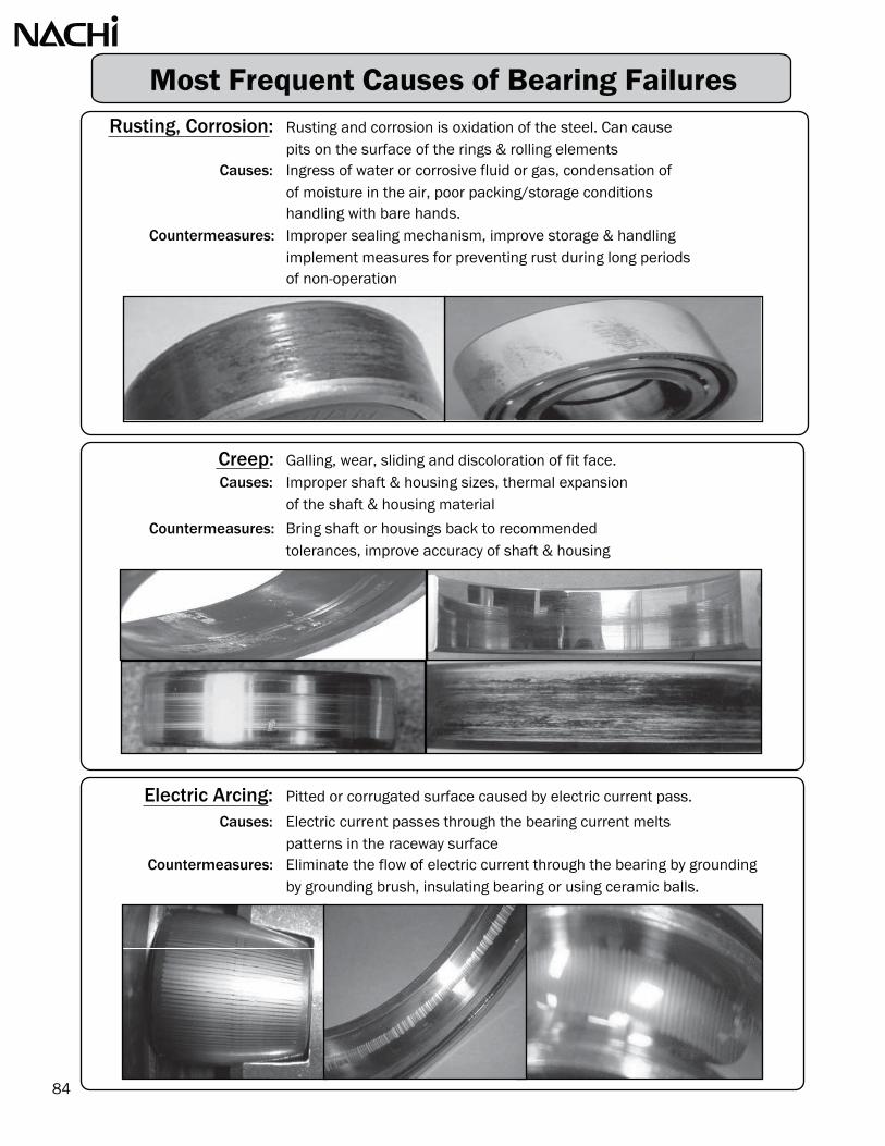
Rusting, Corrosion: Rusting and corrosion is oxidation of the steel. Can causepits on the surface of the rings & rolling elements
Causes: Ingress of water or corrosive fluid or gas, condensation ofof moisture in the air, poor packing/storage conditionshandling with bare hands.
Countermeasures: Improper sealing mechanism, improve storage & handlingimplement measures for preventing rust during long periodsof non-operation
Creep: Galling, wear, sliding and discoloration of fit face.Causes: Improper shaft & housing sizes, thermal expansion
of the shaft & housing material
Countermeasures: Bring shaft or housings back to recommendedtolerances, improve accuracy of shaft & housing
Electric Arcing: Pitted or corrugated surface caused by electric current pass.
Causes: Electric current passes through the bearing current meltspatterns in the raceway surface
Countermeasures: Eliminate the flow of electric current through the bearing by groundingby grounding brush, insulating bearing or using ceramic balls.
84
Most Frequent Causes of Bearing Failures

Bearing Failures
AfterInstallation
AfterPeriodicMaintenance
AfterRe-lubrication
During NormalOperation
• Daily Care:Bearings simply do not break down one day. Before a breakdown occurs, symptoms such as abnormalnoises, increase in vibration and/or increased operating temperature will occur. It is important tocheck and record these characteristics of bearings on regular intervals. With this, historical informationtrends can be identified and maintenance can be scheduled before catastrophic failure occurs.Bearing failures will not affect each of these three symptoms evenly. History will provide a key foreach application as to which symptom to monitor.
• Noise:Audible noise seems to be the number one characteristic used in determining bearing failure. Manytimes it is hard to determine if the noise is coming from the bearing or another component part in themachine. Listening rod and screw drivers & thumbs in the ear are used to try and isolate the bearingnoise.
• Vibration Analysis:Trends in the vibration signatures of equipment is a proven way to determine when maintenanceshould be performed. The vibration signature of each piece of equipment is different. Thesesignatures are sensitive to variation in probe type, location of the probe on the equipment, even theauditor. On critical equipment the probes are mounted permanently and signals related to a controloffice.
• Operating Temperature:Monitoring bearing temperatures is a proven approach and has been used for decades on criticalequipment. Normally the probe contacts the outer ring. The operating temperature fluctuatessince it is a function of the bearing heating up and the environment heating up.
Incorrect DefectsBearing
SelectionBasic Design
Defective Bearing
Cause
Timeline
Lubrication BearingHandling
SealFailure
85

Whining or Insufficient Operating Clearance Contamination Poor Lubrication
Squealing
Rumbling or Excessive Clearance Damaged Rings Contaminated Lube
Irregular
Changein Noise
Temperature Change Damaged Rings
Damaged Rings Contamination
Wear Due to Contaminants or Insufficient Lube
• Bearing Sounds
As shown in the previous table the bearing noise is an indication of many possible bearing situations. The following chart attempts to qualify the audible sounds.
Continuous SoundsZaaaa
Deterioration of surface roughness or
Shaaa damage to the raceways and rolling
Jiiiii elements
Buzzing Tone Resonance, poor fit conditionWoo-woo Deformation of bearing rings, fluttering Goo-goo of elements on raceway
Indeterminate SoundChiritchirit
Foreign matter (dirt)
Piri-piri Creaking of attachment
Pin-pin surfaces
Metal Galling NoiseKii-kii Excessive contact of elements and cage
Gii-gii Insufficient Clearance
Kin-kin Poor Lubrication
CausesSound Features
Uneven Running
Reduced WorkingAccuracy
Symptom During Operation
Operating Condition Potential Source of Trouble
Noise
86
Bearing Failures

MEMO PAGE

Nachi’s website has a BEARING Online Catalog along with assorted brochures.
Click on “Bearings”
button on the left marginClick on >>Technical
Click on >>Specs & Calculations
Bearing Drawings:
Technical Information:
-Dimensions / Tolerance-Load Ratings
-Axial Clearances-Bearing Life-Fit Recommendation-Clearance after Mounting-Vibration Frequencies-Mounting Forces-Grease Recommendations
-Speed Limits-Internal Clearance
www.nachiamerica.com
88

Contributing to progressin the world of manufacturing.

www.nachiamerica.com
Nachi America Inc. - Miami Office2315 NW 107th Ave., Miami, FL 33172 Phone: 305-591-0054Fax: 305-591-3110
Nachi America Inc. - LA Office 12652 Alonda Blvd. Cerritos, CA 90703 Phone: 562-802-0055Fax: 562-802-2455
Nachi Mexicana, S.A. de C.V.Calle Tequisquipan 2, Aerotech Industrial ParkLocalidad Galeras, Municipio de Colon, Queretaro, México C.P. 76295Phone: 52-442-153-2424
Nachi Canada Inc.89 Courtland Ave., Unit No.2 ConcordOntario, L4K 3T4 CanadaPhone: 905-660-0088Fax: 905-660-1146
Fax: 52-442-153-2435
Nachi America Inc.Corporate & Bearing Division Headquarters715 Pushville Road, Greenwood, IN 46143
Fax: 317-530-1012
Phone: 317-530-1002
CATALOG NO.: NAB1202-3May 2017
The appearance and specifications of the products in this catalog may be changed without prior notice if required to improve performance. Every care has been taken to ensure the accuracy of the information contained in this catalog, but no liability can be accepted for errors or omissions.