beaumont quarter - cma+u beaumont.s.pdf · beaumont quarter . auckland, nz commission. design: 2001...
TRANSCRIPT

CMA+U_ Chris Moller Architecture+Urbanism Wellington, New Zealand_ +64 (0)21 774305 [email protected] http://www.cma-u.com
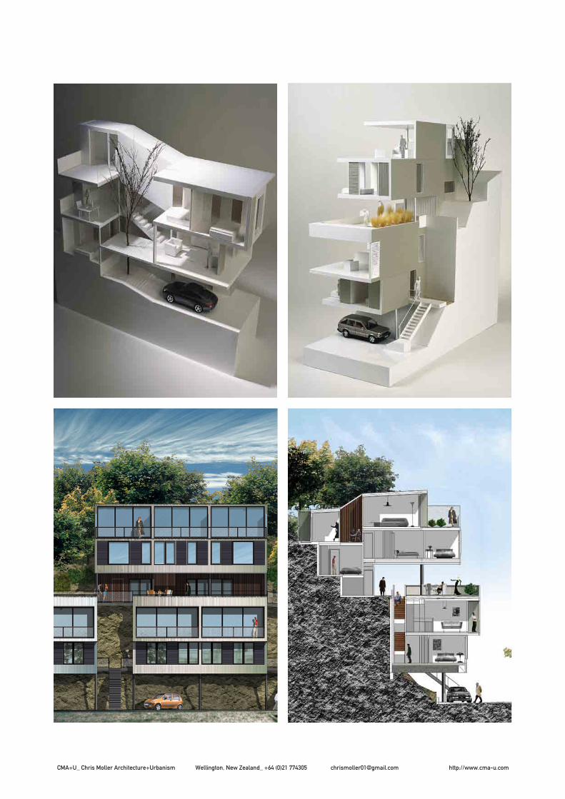
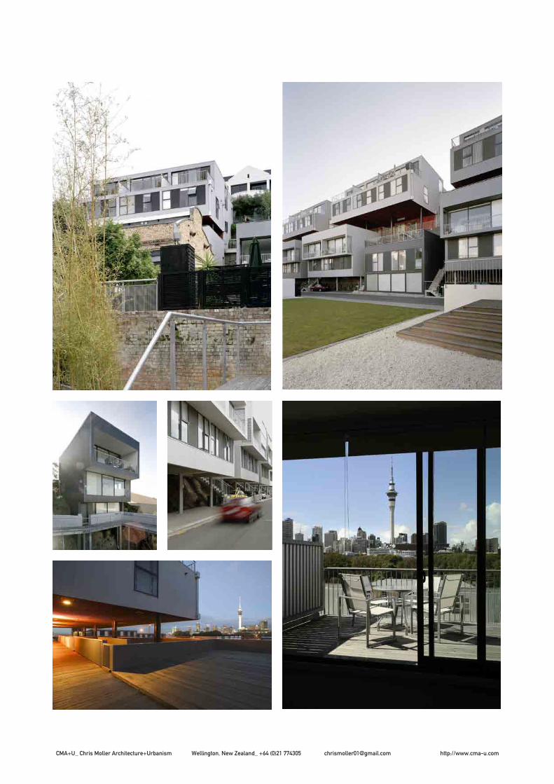
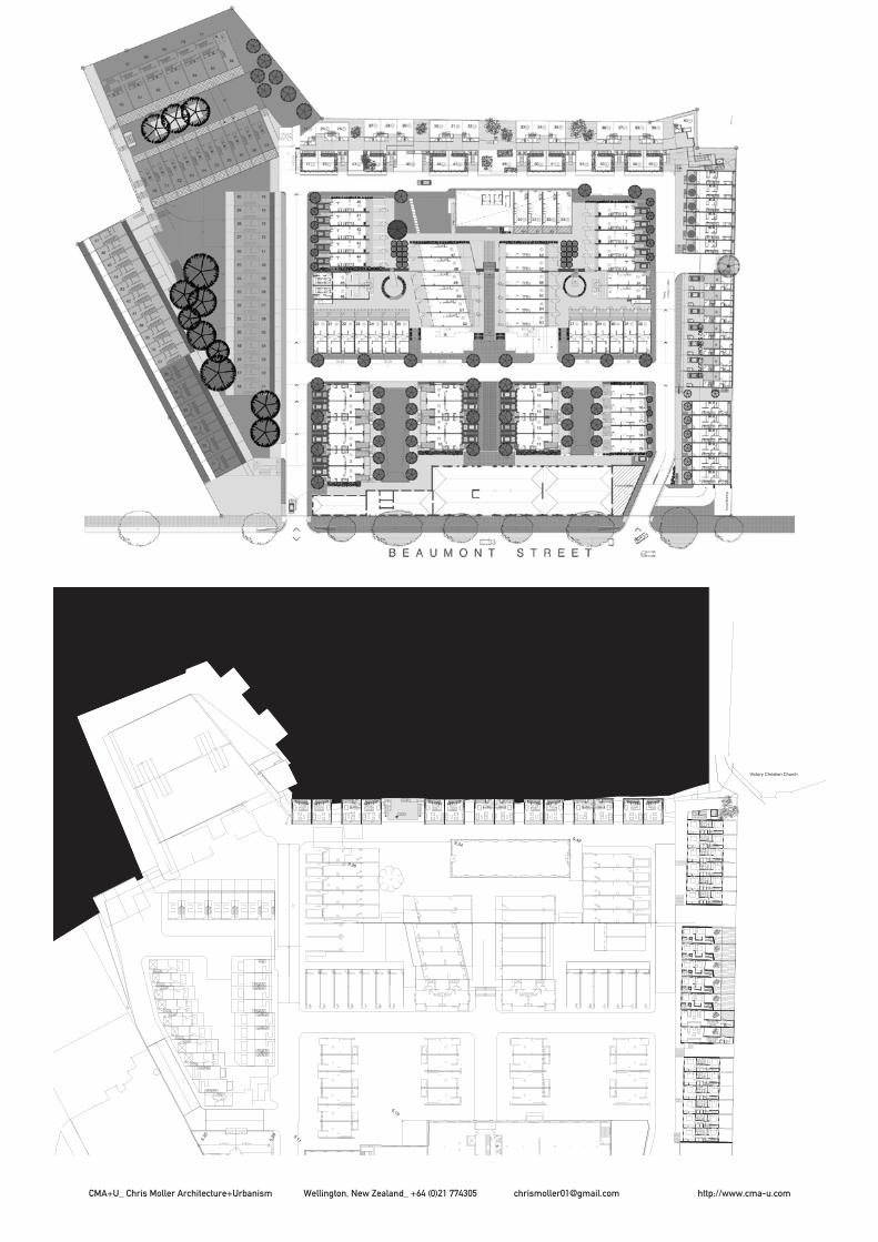
Beaumont Quarter Auckland, NZ
Commission Design: 2001Completion: 2005Site: 0.4 haProgram: Inner city housing: 19 row houses, 32 ‘cliff’ housesClient: Melview Developments Ltd., AucklandAssociates: Studio of Pacific Architecture, WellingtonEngineer: Holmes Consulting Group, AucklandLandscape: Steven Tupu, New YorkBuilding Costs: Euro 5,200,000
51 houses form the second phase of a 250 unit residential development on the edge of the Central Business District in Auckland. This development is a benchmark project in Auckland. It seeks to introduce medium density housing as a means to attract people back to the city. The challenge was to create qualities normally associated with suburban living in such a development and on a very restricted topographi-cal location. The site is of historic importance, once forming the pohutakawa clad water edge. At the beginning of the 20th century the harbour was reclaimed and cut back to form a Gas Works. The slope negotiates the change in topography as it descends to the street at the front of the site.
The project is bound together by a new public space; a board-walk that moves from the park climbing up the cliff top, mak-ing the cliff landscape accessible as part of the street network below. Four houses were conceived (Cliffhanger, Leapfrog, ZigZag and Saddlebag) that are shaped by the different and often contradictory forces present on the site. Motorway noise, minimal footprint, large houses, parking, active street frontage, stunning views across the harbour, sun, privacy and outdoor space. The houses are conceived as a series of simple volumes consistent in materiality but differentiated through subtle colour shifts and typology. Familiar materials such as galvanised corrugated steel and timber are used in a slightly unfamiliar way. The composition of units is a reinterpretation and playful exploration between of the traditional notions of villa and terrace typologies.
CMA+U_ Chris Moller Architecture+Urbanism Wellington, New Zealand_ +64 (0)21 774305 [email protected] http://www.cma-u.com

CMA+U_ Chris Moller Architecture+Urbanism Wellington, New Zealand_ +64 (0)21 774305 [email protected] http://www.cma-u.com
CMA+U_ Chris Moller Architecture+Urbanism Wellington, New Zealand_ +64 (0)21 774305 [email protected] http://www.cma-u.com

CMA+U_ Chris Moller Architecture+Urbanism Wellington, New Zealand_ +64 (0)21 774305 [email protected] http://www.cma-u.com

CMA+U_ Chris Moller Architecture+Urbanism Wellington, New Zealand_ +64 (0)21 774305 [email protected] http://www.cma-u.com
CMA+U_ Chris Moller Architecture+Urbanism Wellington, New Zealand_ +64 (0)21 774305 [email protected] http://www.cma-u.com
E
272.7 m 264.9 m
268.9 m
10.42
5.30
5.06
5.01
5.115.29
5.02
9.26
9.54
5.19
9.49
1- 2-
3-
A B
C
Stair Stair
Victory Christian Church
DD.54
+15.100
00
Stair Stair Stair Stair
Stair
Stair
Stair
Stair
Stair
Stair
Stair
Stair
Stair
Stair
Stair Stair
000
Living & DiningRoom
Terrace
DW
Kitchen
PantryFStair
Living & DiningRoom
Terrace
F
DW
Kitchen
pantry
Stair
store
LEVEL 2

CMA+U_ Chris Moller Architecture+Urbanism Wellington, New Zealand_ +64 (0)21 774305 [email protected] http://www.cma-u.com

CMA+U_ Chris Moller Architecture+Urbanism Wellington, New Zealand_ +64 (0)21 774305 [email protected] http://www.cma-u.com
DC
Elevations
A1
LEAP FROG HOUSE
1:50 @ A1; 1:100 @ A3.
Type 2 House14 April 2003
833.92.WD LF 30-03 rE Elev E
General Notes: Notes:
Drawing Title:
Studio of Pacific Architecture Ltd.Architecture, Urban Design, Interior Design2nd Floor, Hibernian House, 89 Willis Street,P.O. Box 11-517 Wellington,New Zealand.Tel: (04) 473 6444, Fax: (04) 499 1888
Project Title:
Date:
Original size: Drawn:CAD Reference:Revisions Description Init. Date
Studio of Pacific Architecture Dwg No:
Scale:Checked:
PO Box 6501, Wellesley StA u c k l a n dTel: (09) 379 9666Fax: (09) 379 9667
Grange ProjectsLimited Proposed new residential development
at 20 Beaumont Street, Auckland, Being Part Lot 2, DP 92489for Grange Projects Ltd 833
S T A G E 2
revision:
Revisions:
All dimensions to be checked on site. Copyright in alldrawings, specifications and other documents and in thework executed from them remains the property of Studio ofPacific Architecture Limited.© Copyright 2003 Studio of Pacific Architecture Ltd
Beaumont Quarter, Auckland
43-0943-08&
R.L. +0.0
R.L. +2.685
R.L. varies
3,000
2,20
0
628
2,20
0
4,471
eq eq
1,00
01,
400
eq eq
1,50
085
0
C
E
E
SCALE 1:501
11-03
Note: Refer Group Setout Plans for location of Type 1 and Type 2 Houses and for location of houses with plans mirrored to that shown above.
Note: Refer Group Setout Plans for location of Type 1 and Type 2 Houses and for location of houses with plans mirrored to that shown above.
NOTE: FIRE RATED CLADDING EXTENT NOT SHOWN - Refer ammended Fire Report - awaiting Peer review
ELEVATION - Type 2 House - UNIT 55 ONLY
LEVEL 1
LEVEL 2
ROOF LEVEL
Aluminium C section screen.
CLIFF HANGER ABOVE
GROUND LEVEL
PUBLIC BOARDWALK
Concrete block wall behind - refer plans.
PRIVATE TERRACE
Overflow from roof terrace. Align horizontally with vent grille.
WL20
ROOF LEVEL
Overflow from roof terrace. Align horizontally with vent grille.
Cap flashingHandrail
Entry Stair. Refer to detail 43-11 for stair connection to house. Also refer to Engineers drawing S04-04 for stair details
Vent grille to be located within zone set by parameters shown.
Selected profiled metal cladding on strappiing over concrete block wall.
Selected profiled metal cladding.
Frosted glass to door.
Vent pipe and beamdashed behind
Clean edge to corrugateat base. Minimum 150mmclear to clifface. Architectto check detail on site and advise after cliff excavation.
Note height of cliff hanger above Leapfrog varies. Refer group setout plans and elevations.
Services pipes on ground surface. Conceal if possible(Shown indicatively only)
Please price for metal screensin front of these windows similarto T-House detail 46-09. (Fixingsdifferent). Purchaser to review costs and advise if screensto remain.NOTE: Screens are proud ofexternal wall surface.
WL28
WL27
Windows WL27 & WL28 Added
L3 L4L2L1
RWH with overflow
DP
Villaboard to soffit over external stair. Soffit level with internal ceiling line
43-061
R.L. varies
E
Wall packed out on ex75mm framing.
Selected profiled metal cladding.
PARKING
GROUND LEVEL
Note: Refer Group Setout Plans for location of Type 1 and Type 2 Houses and for location of houses with plans mirrored to that shown above.
Note: Refer Group Setout Plans for location of Type 1 and Type 2 Houses and for location of houses with plans mirrored to that shown above.
NOTE: FIRE RATED CLADDING EXTENT NOT SHOWN - Refer ammended Fire Report - awaiting Peer review
Downpipe from covered terrace deleted. Outlet through soffit to spill onto road below.
R.L. +0.0
R.L. +2.685
R.L. +6.545
R.L. +5.785
eqeq
eq eq eq eq
eqeq
1/3 1/3 1/3
2,70
0
400
2,00
0
L- L-
LEVEL 1
LEVEL 2
ROOF LEVEL
PARAPET LEVEL
Villaboard soffit
Villaboard soffit
Villaboard lined fin wall between houses.
Cap flashing
ENTRY STAIR
Neighbouring House
WL24
WL22 WL21
Handrails
Mesh balustradeRefer Detail 50-11
Baby corrugated cladding infill panels - horizontal.
Baby corrugated cladding.
WL24
(WL24 redrawn for clarity)
SCALE 1:502 ELEVATION - Type 2 House
11-03
LFDCE Purchaser Changes 14.04.03 30-03
-2
eq eq 200400 800
FRONT ELEVATIONSCALE 1:50
BOARDWALKNot shown for clarity-REF.. NOTE 1
-3
5,000
eq eq 500
1,830
2,20
0
0.000
1.770
3.180
4.620
5.910
28.020
F
C-C-
FUJI HEIGHT LIMIT-DO NOT EXCEED
SCALE 1:50
C-
REAR ELEVATION - Type 1S
WC-11
WC-09
WC-11 behind
Flashing
External gutter
DP Beyond
Profile of cliff indicative only - varies-REF... NOTE 1
WC-11 shown separately for clarity
Refer to 4/30-01 fordimensions of WC-09
Not shown for clarity-REF.. NOTE 1
LEAPFROG BELOW
-4
3.180
4.620
5.910
28.020eq eq
2,20
01,
440
760
530
2,50
0
50 2,500 301
50 1,875 9261,250 625
C.16
WC-09
WC-06F
SCALE 1:50
TCE-EAST ELEVATION
TERRACE
C-
Vent pipe beyond
DP
External Gutter
Alig
n
Baby Corrugate cladding
Oscure Glass
Solid Balustrade
AXONOMETRIC VIEW-FOR INFORMATION ONLY

CMA+U_ Chris Moller Architecture+Urbanism Wellington, New Zealand_ +64 (0)21 774305 [email protected] http://www.cma-u.com
F. Issued for Construction 18.10.99
DCAs Noted
PM833.92.WD ZZ_30-01_r Elev
Elevations
A1
ZIG-ZAG HOUSE
3
11 March 2002
960
Level 1 - Living
Level 2 - Bedrooms
Ground Level - 3200
Ground Level - 3700
2,40
0
9,20
0
2,70
0
Ground Level - 2730
3,15
0
SOUTH ELEVATIONSCALE 1:50
1
40-00-
40-00-
40-00-
40-00-
40-00-
11-01
40-00-
Z- Z-
WZ01
WZ02
WZ05 WZ04
WZ17 WZ16 WZ1540-00
-
40-00-
40-00-
Gro
und
floor
hei
ght v
arie
s,
lowe
st o
ptio
n sh
own
Clearglass
Clearglass
Clearglass
Clearglass
Clearglass
Clearglass
ClearglassClear glass
Mesh Balustrade
Sloped ground slab
Selected metal profile wall cladding.
Tree - dashed. Shown indicative onlySelected metal profile cladding.
DP at back of parking area.
1,00
0
3,24
42,
365
eq eq
Ground Level -
Level 1 -
WZ09a
Z- Z-
Mesh balustrade
RWH with overflow
DP
Void in roof over patio area. Refer to Courtyard elevations for elevations of this area.
Flashings - refer group roof plan
Selected profiled metal roofing.
Selected profiled metal wall cladding.
glass glass
Note height difference to WZO9b on 4 storey house option.
Kitchen / Dining
Bathroom 1
SCALE 1:50NORTH ELEVATION3
11-01
General Notes: Notes:
Drawing Title:
Studio of Pacific Architecture Ltd.Architecture, Urban Design, Interior Design2nd Floor, Hibernian House, 89 Willis Street,P.O. Box 11-517 Wellington,New Zealand.Tel: (04) 473 6444, Fax: (04) 499 1888
Project Title:
Date:
Original size: Drawn:CAD Reference:Revisions Description Init. Date
Studio of Pacific Architecture Dwg No:
Scale:Checked:
PO Box 6501, Wellesley StA u c k l a n dTel: (09) 379 9666Fax: (09) 379 9667
Grange ProjectsLimited
Proposed new residential developmentat 20 Beaumont Street, Auckland, Being Part Lot 2, DP 92489for Grange Projects Ltd 833
S T A G E 2
revision:
All dimensions to be checked on site. Copyright in alldrawings, specifications and other documents and in thework executed from them remains the property of Studio ofPacific Architecture Limited.© Copyright 2002 Studio of Pacific Architecture Ltd
Revisions:
Beaumont Quarter, Auckland
Level 2 - Bedrooms
Level 1 - Living
Ground Level - 3700
Ground Level - 3200
d Level - Bathroom 1
1 - Kitchen/Dining
Ground Level - 2730
Z1Z5 Z3Z4 Z2
glass
glass glass
BOUN
DARY
SCALE 1:5011-014 WEST ELEVATION
ZZ 30-01
1.0 Elevations shown are generic - note individual differences between houses: Ground floor height varies; Double framing required insome locations to account for changes iun roof levels between certain houses; and double framing required at east and west group end elevations (hpouses 7 & 13).Refer to: group plans, group elevations and details.
Approx NorthDC
As NotedPM
833.92.WD ZZ_11-01_r
GA Floor Plans
A11
ZIG-ZAG HOUSE 25 February 2002
General Notes: Notes:
Drawing Title:
Studio of Pacific Architecture Ltd.Architecture, Urban Design, Interior Design2nd Floor, Hibernian House, 89 Willis Street,P.O. Box 11-517 Wellington,New Zealand.Tel: (04) 473 6444, Fax: (04) 499 1888
Project Title:
All dimensions to be checked on site. Copyright in alldrawings, specifications and other documents and in thework executed from them remains the property of Studio ofPacific Architecture Limited.© Copyright 2001 Studio of Pacific Architecture Ltd
Date:
Original size: Drawn:CAD Reference:Revisions Description Init. Date
Studio of Pacific Architecture Dwg No:
Scale:Checked:
PO Box 6501, Wellesley StA u c k l a n dTel: (09) 379 9666Fax: (09) 379 9667
Grange ProjectsLimited
Proposed new residential developmentat 20 Beaumont Street, Auckland, Being Part Lot 2, DP 92489for Grange Projects Ltd
Revisions: FOR CONSTRUCTION
833
S T A G E 2
revision:
Beaumont Quarter, Auckland
150
1292,9281101,704129
13902,964901,7409013
1,00
090
4,84
090
4,90
090
2,88
490
920
906
990
110
4,82
010
64,
888
106
2,86
411
090
010
6
5,000
129eqeqeqeqeq129
129900110
9001062,738118
15,0
00
110
895
10012
0 100
990
5,03
64,
888
4,08
0
966
124
4,80
013
689
450
3,05
089
411
03,
870
106
998
904,
836
9091
650
3,05
090
490
3,89
090
RL: +0.0
RL: +0.0
RL: +1.440
RL: +0.0
RL: +1.440
A35-01
A35-01
A35-01
A35-01
45
WZ08
WZ0
7
1
34
51
2
23
Stai
r6
78
9
67
OUT
SIDE
OF
LINI
NGS
Hand
rails
- da
shed
OUT
SIDE
OF
LINI
NGS
SETO
UT T
O F
RAM
E
SETOUT TO FRAMEOUTSIDE OF LININGS
JOINERYOVERALL
Level 3 over - dashed - 4 storey option only.
BALCONY
WZ04WZ05
SCALE 1:50LEVEL 1 PLAN
Z5
Z4
Z3
Z2
Z1
Za Zb
RWH/ DP
40-00-
40-00-
LIVING ROOM / FAMILY ROOM
WZ06
DP
Stai
rSt
air
OUTSIDE OF LININGS
KITCHEN / DINING
BALCONY
RWH with overflow / DP
WZ09
DP
OVE
RALL
SETO
UT T
O F
RAM
E
Trim out hole in Patio decking to allow for tree.
GRI
D SE
TOUT
Finished decking level
Finished decking level
PATIOFinished decking level
150
903,
245
9062
590
2,78
090
110
2,93
011
090
011
01,
700
110
940
110
110
3,22
511
060
511
02,
760
106
902,
950
9092
090
1,72
090
960
90
1291,8001109231101,800129901,83690943901,8369013
129900110
6001103,023129RL: +3.030
A35-01
A35-01
A35-01
A35-01
SETO
UT T
O F
RAM
EO
UTSI
DE O
F LI
NING
S
DZ12
DZ14
97 Ha
ndra
il - d
ashe
d
56
8
Void
to s
tair
belo
wDZ
10
4
SCALE 1:50level 3 - 4 storey option level 2 - 3 storey option
Z5
Z4
Z3
Z2
Z1
Za Zb
BEDROOM
BATHROOM 2 BEDROOM
WZ17 WZ16 WZ15
DZ11HWC
UPPER FLOOR PLAN:
Refer to Roof plan
RWH/refer roof plan
Tree
Void to patio below
DZ15
WZ18
Stai
r
OUT
SIDE
OF
LINI
NGS
SETO
UT T
O F
RAM
E
ROBE
DZ13
ROBE
OUTSIDE OF LININGS
FWG
OUTSIDE OF LININGSSETOUT TO FRAME
40-00-
40-00-
DP
Level for Type 1 - 3 storey option only.
100
2,00
0
100
150
150
150
A35-01
A35-01
A35-01
A35-01
RWH withoverflow
Flashing. approx 250mm wide - confirm. Refer detail.
Flashing. refer detail.
RWH withoverflow
Tree indicated below.
Void to patio below
40-00
40-00
Capping flashing. Confirm width. Refer detail.
-
40-00-
Flashing. approx 250mm wide - confirm. Refer detail.
Formed hidden gutter. refer detail.
Capping flashing. Confirm width. Refer detail.
Flas
hing
.
Selected long run metal cladding
50mm dia. waste vent pipe moves back from its location within south elevation wall to l;ocation shown in flashing strip.
Approx 400mm wide flashing strip to allow services through roof. Overflashing to continue past penetration.
Fall:
4 d
egre
e pi
tch
Fall:
4 de
gree
pitc
hFa
ll: 14
deg
ree
pitc
h - a
ppro
x
Flashing.
SCALE 1:50
NOTE: roof relationship between different Zig-Zag properties varies. Refer to Zig-Zag Block elevations to see whether roofing continous across properties or stepped and requires flashing. Also note double framing required where heights step between houses and for end elevations.ROOF PLAN - 3 storey option.
Z5
Z4
Z3
Z2
Z1
Za Zb
Formed hidden gutter. refer detail.
Void to neighbouring patio below
-
ZZ 11-02