before the hearings commissioners at christchurch under...
TRANSCRIPT

Before the Hearings Commissioners At Christchurch UNDER the Resource Management Act 1991 AND IN THE MATTER OF Applications by MainPower New Zealand
Limited, Rooney Group Limited, Rooney Farms Limited and Kakapo Joint Venture Limited to Canterbury Regional Council for resources consents for the Kakapo Brook Hydro-Irrigation Project at Glynn Wye Station, North Canterbury
STATEMENT OF EVIDENCE OF JOHN ADRIAN DE RUYTER
Dated 2 October 2015

2
STATEMENT OF EVIDENCE OF JOHN ADRIAN DE RUYTER
Introduction
1. My name is John Adrian de Ruyter.
2. I am a Charted Professional Civil Engineer (CPEng, MIPENZ, IntPE) with 15 years’
experience primarily working in the design, construction, and construction
supervision of stormwater, potable water, wastewater and irrigation projects.
3. I have worked for Rooney Earthmoving Limited (REL) for 3 years specialising in
irrigation projects. My role as a Civil Engineer includes feasibility studies /concept
design / detailed design to construction monitoring for irrigation schemes. The
irrigation schemes I have worked on include; Rangitata South Irrigation Scheme,
Waimakariri Irrigation Scheme, Maerewhenua Irrigation Scheme, Waihao Downs
Irrigation Scheme and Winterburg Irrigation Scheme.
4. As a Graduate Engineer I worked for the Manawatu Whanganui Regional Council
working on river flooding and erosion projects for 2 years. I then worked for Opus
International Consultants for 9 years and I was based in Christchurch for 8 years
working on water related projects in the Canterbury Region.
5. I hold a BE (Hons) (CIVIL) degree from the University of Canterbury and I am
currently a Charted Professional Engineer and full member of IPENZ.
6. In preparing my evidence, I have reviewed the following documents:
a. The Application;
b. The Applicants’ section 92 further information response;
c. The Applicants’ evidence;
d. Submissions; and
e. The Canterbury Regional Council’s section 42A Officers’ Report.
Scope of Evidence
7. In my evidence I have been asked by the Applicants’ to provide an overview and
outline of the preliminary:
a. Intake design;
b. Fish screen design;
c. Race network;
d. Storage facility design; and
e. Scheme automation.
3
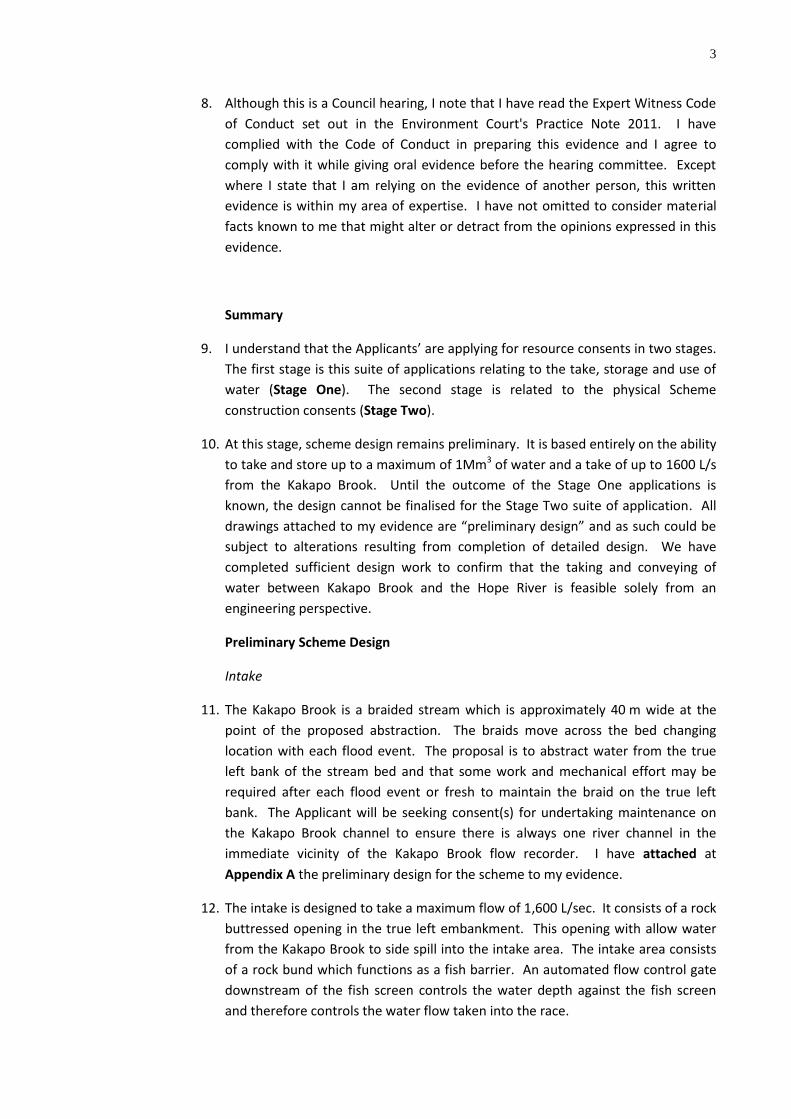
8. Although this is a Council hearing, I note that I have read the Expert Witness Code
of Conduct set out in the Environment Court's Practice Note 2011. I have
complied with the Code of Conduct in preparing this evidence and I agree to
comply with it while giving oral evidence before the hearing committee. Except
where I state that I am relying on the evidence of another person, this written
evidence is within my area of expertise. I have not omitted to consider material
facts known to me that might alter or detract from the opinions expressed in this
evidence.
Summary
9. I understand that the Applicants’ are applying for resource consents in two stages.
The first stage is this suite of applications relating to the take, storage and use of
water (Stage One). The second stage is related to the physical Scheme
construction consents (Stage Two).
10. At this stage, scheme design remains preliminary. It is based entirely on the ability
to take and store up to a maximum of 1Mm3 of water and a take of up to 1600 L/s
from the Kakapo Brook. Until the outcome of the Stage One applications is
known, the design cannot be finalised for the Stage Two suite of application. All
drawings attached to my evidence are “preliminary design” and as such could be
subject to alterations resulting from completion of detailed design. We have
completed sufficient design work to confirm that the taking and conveying of
water between Kakapo Brook and the Hope River is feasible solely from an
engineering perspective.
Preliminary Scheme Design
Intake
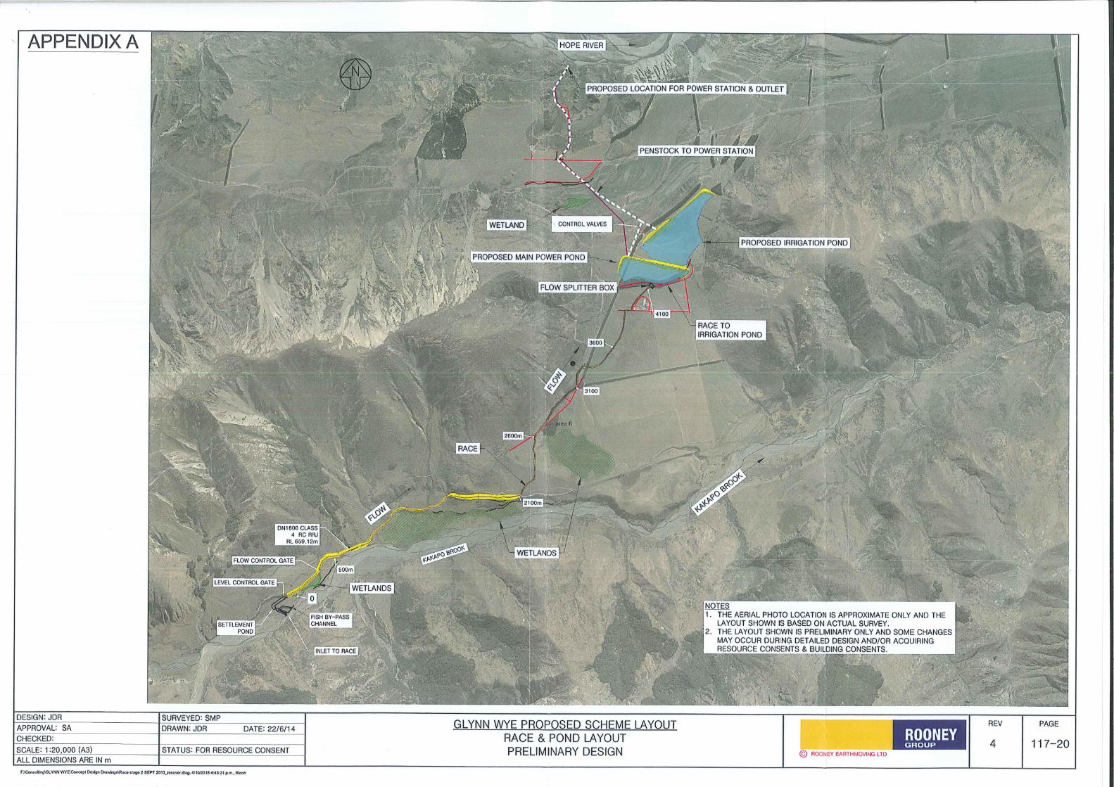
11. The Kakapo Brook is a braided stream which is approximately 40 m wide at the
point of the proposed abstraction. The braids move across the bed changing
location with each flood event. The proposal is to abstract water from the true
left bank of the stream bed and that some work and mechanical effort may be
required after each flood event or fresh to maintain the braid on the true left
bank. The Applicant will be seeking consent(s) for undertaking maintenance on
the Kakapo Brook channel to ensure there is always one river channel in the
immediate vicinity of the Kakapo Brook flow recorder. I have attached at
Appendix A the preliminary design for the scheme to my evidence.
12. The intake is designed to take a maximum flow of 1,600 L/sec. It consists of a rock
buttressed opening in the true left embankment. This opening with allow water
from the Kakapo Brook to side spill into the intake area. The intake area consists
of a rock bund which functions as a fish barrier. An automated flow control gate
downstream of the fish screen controls the water depth against the fish screen
and therefore controls the water flow taken into the race.

4
Fish Screen
13. The preliminary fish screen design was undertaken using NIWA’s document; “Fish
screening: good practice guidelines for Canterbury” (2007). The concept design is
attached as Appendix “B” to my evidence. The proposed fish screen will be a
porous rock bund with the following rock grading:
Note: % Passing indicates what percentage of rocks will be smaller than the stated
rock size i.e. in the above table, 50% of the rocks will be smaller than 0.25m.
14. The rock is typically oversized river stone or quarry rock. The rock will be “well
graded” meaning there will be an equal quantity of rocks sizes between 0.15m to
0.6m. This type of screen has been adopted for the following schemes:
a. Acton Irrigation intake,
b. Rangitata Irrigation Scheme,
c. Maerewhenua Irrigation Scheme
d. Winterburg Irrigation scheme, and
e. Waihao Downs Irrigation Scheme.
It has also been adopted on a number of smaller stream offtakes in the McKenzie
basin.
15. The following parameters are stated in NIWA’s fish screen guideline and were
incorporated into our design of the fish screen;
a. locate the fish screen as close as practical to the river,
b. minimise the size of the openings in the screen,
c. limit the approach velocity to 0.12 m/s,
d. ensure the sweep velocity is greater than the approach velocity,
e. provision of a fish return channel that transports the fish safely away from
the screen back into the main river.
16. To ensure the approach velocity is achieved, the required wetted area of the rock
fish screen is 40m2 for 1,000 L of water take. This minimum wetted area has been
estimated by NIWA and is stated in Mr. Bonnet’s evidence. The required wetted
area for 1,600 L/s is 64m2. The proposed wetted area for the Glynn Wye fish
screen is 116m2 which is approximately 1.8 times larger than the required
Rock Size (m) % Passing
0.5 - 0.6 100
0.25 50
0.15 0
5
minimum of 64m2. The over sizing of the rock fish screen allows for clogging of
the fish screen and should decrease the frequency of maintenance on the screen.
17. The proposed width at the top of the fish screen is 2m. The minimum width of
rock that the water flows through is estimated at 6m.
18. All water which is taken into the supply race must pass through the rock bund
ensuring that all water is screened. I understand from experience, and various
NIWA reports associated with this Application and the evidence of Mr. Bonnett,
that a rock bund provides a physical barrier to salmonid fish which prefer not to
swim into the dark cavernous voids of the rock bund. Special care is taken in the
design and sizing of this barrier, including consultation and advice sought from Mr.
Bonnett, to ensure that appropriate approach and sweep velocities are achieved
to deter and prevent fish from entering the barrier.
19. Fish by-pass: The fish by-pass is required to ensure that fish that enter the intake
channel are able to safely return to the river. Mr. Bonnett has confirmed that a
water depth of 100mm should provide a safe passage back to the river.
Preliminary channel design estimates that a flow of 30 L/s is required to achieve a
water depth of 100mm. The exact geometry and layout for the fish by-pass
channel will be confirmed during Stage 2 detailed design with approval by Mr.
Bonnett.
Settlement pond
20. All water flowing into the supply race passes through a settling pond. This is
designed to slow the velocity to <0.1m/sec with a retention time exceeding
45min. All sediment from coarse silt to sand are expected to settle out in this
pond. This sediment will be removed approximately once a year and disposed of
at a suitable location on the farm where it cannot be dispersed into any wetland
or flowing water. The sediment will not be disposed back into the river.
21. The fine / medium silt particles will stay in suspension and will either settle out in
the 4.1 km race or be carried to the storage facility. During Stage 2 design we will
review the possibility of delaying the construction of the settlement pond so the
full sediment load enters the race network. This will allow sediment to settle out
in the race and assist in the sealing of the race and pond therefore reducing losses
(refer to paragraph 26). The feasibility of this will be confirmed during Stage 2
detailed design.
22. Two automated control gates are located at the head of the supply and transfer
race. The operation of the first control gate is discussed in Paragraphs 33 to 37 in
my evidence. The second automated gate will be solely installed to ensure the
water level in the adjacent wetland. This gate will remain closed when no water is
being taken from Kakapo Brook therefore maintaining water levels in the adjacent
wetland.
6
Race Network
23. The preliminary race design is attached as Appendix “C” to my evidence. The
transfer race is approximately 4.1km long and is capable of conveying the
consented flow. The grade of the race is designed at 1:1000 which controls the
velocity to <0.7m/sec.
24. For the first 2km the race follows the contour, gradually climbing the terrace. It is
a cut to fill construction with the race being formed from in-situ materials. The
preliminary race design has a 4m access berm located on the outside edge. The
race may have underdrains in the form of drainage blankets to ensure
uninterrupted flow to the wetlands is achieved. One siphon under an unnamed
stream and one access crossing are proposed for this section.
25. The second 2km follows the contour across the flats behind the terrace. It is
primarily a cut to waste construction with the race being formed into the in-situ
material. The preliminary design is for a race that follows the contour of the land
and avoids the remaining wetlands. Four to five vehicle crossings have been
allowed for over this section of race.
26. We are employing a 100% naturally lined system for the race and a source of clay
for lining has been identified at Glynn Wye. This clay will be used to seal sections
of the race where required. Further sealing of the race will occur once the scheme
is operational due to the settlement of sediments along the race (refer to
paragraph 21) In my experience, the sealing of the race will take a 2 to 4 year
commissioning process and the active sealing of the race will continue until there
is no appreciable loss.
27. The loss of water equates to a direct financial loss and this is addressed in the
evidence of Mr. Hurley and Dr. Draper. Therefore, it is in the best interests of the
Applicants to undertake all reasonably practicable measures to reduce any losses
as much as possible.
28. The transfer race terminates at the storage ponds.
Storage Ponds
29. The preliminary storage pond design is attached as Appendix “D” to my evidence.
Storage for both power generation and irrigation is essential. The amount and
timing of water from the Kakapo Brook has resulted in significant storage volumes
being required.
30. The storage ponds are located in Dismal Valley between the Kakapo Brook and
Hope River. The ponds are located on natural terraces and require the
construction of only one earth embankment along the lower terrace. The exact
configuration of the storage component has not yet been determined but the
total required for both irrigation and power generation will not exceed
1,000,000m3.

7
31. Power generation will have a portion of dedicated storage. Irrigation and hydro
will share the remainder of the facility. All water will be split, measured and
logged into each pond.
32. The storage pond embankments will be constructed from natural in-situ materials.
Both natural and synthetic liners inside the pond will be considered during
detailed design for Stage Two applications and the building consents. Water
depths and the availability and the suitability of natural materials will influence
this design component after further investigations have been completed. Refer to
the evidence of Mr. Ian McCahon.
Scheme Automation
33. Automation of the scheme is essential to ensure that the correct flow is taken and
to log / record flows in accordance with resource consent conditions. The
proposed automation will be based on systems installed in irrigation schemes such
as Rangitata and Waihao Downs. The automation will be designed and installed
by competent experts and a schematic plan of the key components is included in
Mr. Hurley’s evidence.
34. The allowable water take is dependent on the flow measured in Kakapo Brook and
at the Marble Point flow recorder on the Waiau River. There are set flows for
both rivers at which the taking of water for power generation and irrigation must
cease. Therefore the key to the automation system is measuring the Kakapo
Brook flow and obtaining flow data form the Waiau River (Marble Point) flow
recorder. Computer logic (software) will analyse the measured flow data from the
two rivers and calculate the allowable take for power generation or irrigation.
35. A stilling well will be installed in Kakapo Brook to measure the river flow. The
stilling well will be located in a stable section of river adjacent to the scheme
intake. Larger flows are likely to alter the river channel and we will be required to
undertake maintenance to ensure the stilling well is accurately measuring the
river flow. The Applicant will be seeking consent(s) for undertaking maintenance
on the Kakapo Brook channel to ensure there is always one river channel in the
immediate vicinity of the Kakapo Brook flow recorder.
36. A hydraulic flow control gate will be installed at the start of the race network
(downstream of the fish screen and settlement pond). Downstream of the
hydraulic gate will be a weir and stilling well that will measure the actual flow
taken into the scheme. This measured flow will be sent to the scheme computer
and compared to the calculated allowable water take and the gate height adjusted
so the correct flow is being taken.
37. Flow levels in the Kakapo Brook will be logged every 15 minutes and gate
positions adjusted accordingly. Should any of the key components fail then the
scheme system will send out an alarm notifying key personal to the problem.
38. Immediately upstream of the ponds is a flow splitter box which is a reinforced
concrete box with a flow control gate. The height of the control gate will be

8
adjusted to allow the correct flows to be diverted to the irrigation and power
generation ponds. A stilling well will measure the flow diverted to the irrigation
pond.
Power Generation Building & tailrace to Hope River
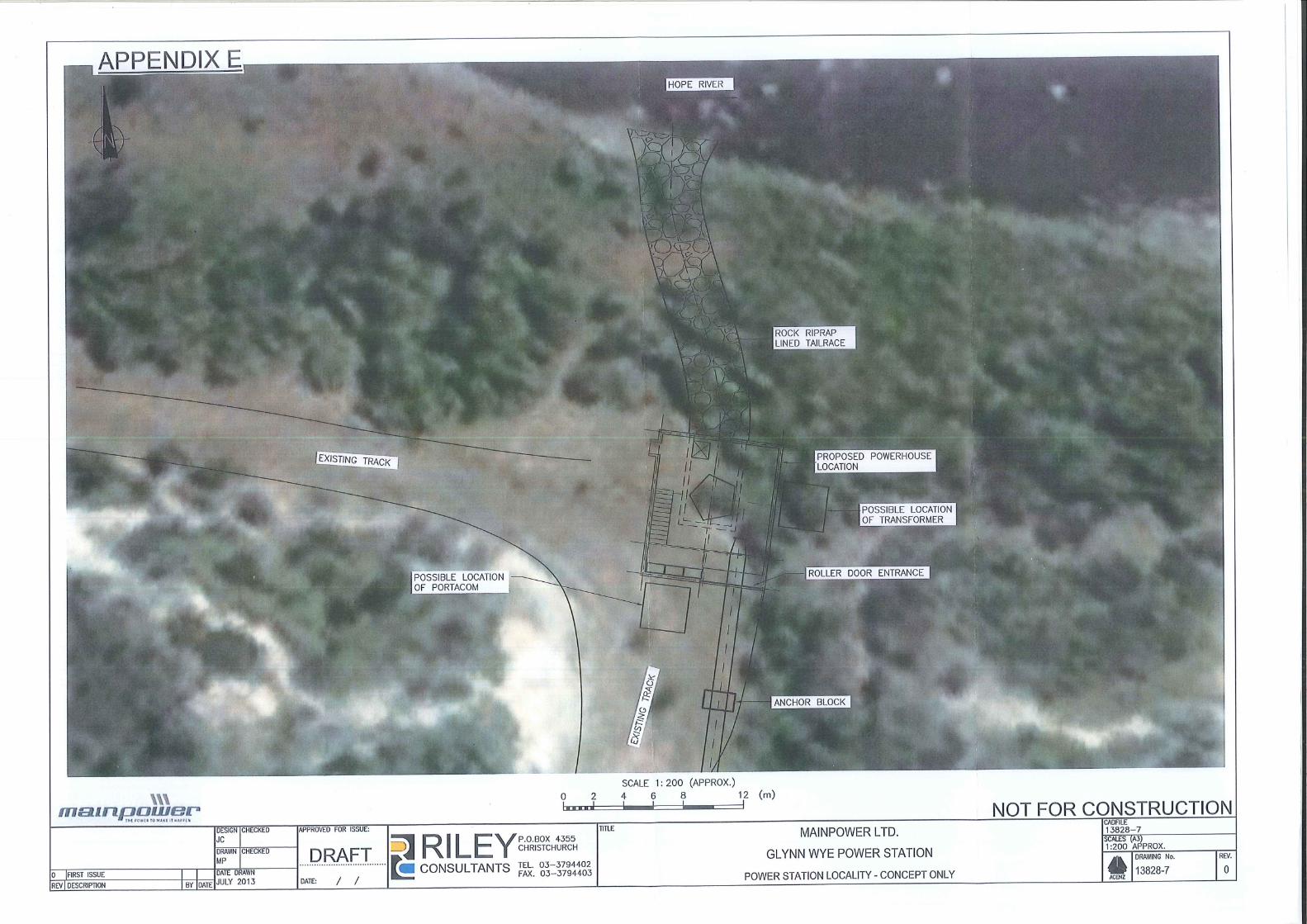
39. Main Power have engaged Riley Consultants Ltd to undertake the preliminary
design for the power generation and tailrace discharge into the Hope River. Two
preliminary design plans from Riley Consultants are attached at Appendix E and
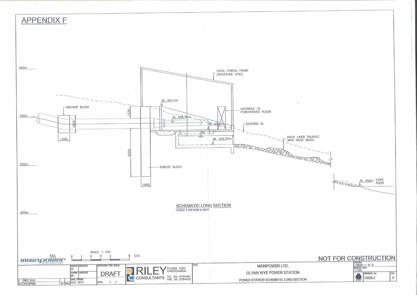
Appendix F to my evidence. Appendix E is a plan view showing the location of the
power house and the tailrace. Appendix F is a long section through the power
house and tailrace to the Hope River.
40. The Riley Consultants plans show the tailrace will be lined with rock riprap to
prevent scouring of the Hope riverbed. A series of weirs will be constructed to
reduce the velocities of discharge water into the Hope River. The tailrace will be
designed to ensure that erosion (scouring) of the bed and banks of the Hope River
is prevented. The final design will be confirmed during Stage 2.
Section 42A Officer’s Report
41. I have reviewed the Section 42A Officer’s report with respect to this application. I
have identified paragraphs relevant to engineering and responded below;
Natalie van Looy’s report
Paragraph 77 states it is unclear whether the proposed pond embankments
height trigger the definition of a “large dam” therefore requiring a building
consent. However, we have confirmed the height of the ponds will require a
Building Consent to be lodged and the preliminary Dam Break analysis is covered
in the evidence of Mr. Strayton.
Paragraph 119 states we have not addressed efficiency of the race network or
ponds. I have addressed efficiency and losses earlier in my evidence in
paragraphs 25 & 26.
Mr. Adrian Meredith evidence
Mr. Adrian Meredith discusses the proposed fish screen in his evidence in
paragraphs 51 to 77. Mr. Bonnett has replied to Mr. Meredith’s concerns within
his evidence.
9
Conclusions
42. The final design for the scheme infrastructure will be completed during Stage 2.
Sufficient design has been undertaken to confirm that the construction and long
term operation of the scheme is feasible.
43. Fish Screen: The fish screen has been designed in accordance with NIWA’a “Fish
screening; good practice guidelines for Canterbury” and with assistance from Mr.
Bonnett. Final approval of the fish screen design will be required before the fish
screen is constructed.
44. Efficiency: The Applicants are committed to ensuring that water losses through
the scheme are minimized to ensure maximum financial benefit is gained. Lining
sections of the race will be completed as required and further sealing of the race
will occur during the operation of the scheme.
45. Automation: The scheme automation will be able to measure / record flows in
Kakapo Brook and receive flow data from the Marble Point flow recorder. Inputs
from flow recorders will send data to a computer that will calculate the allowable
water take and send output signals to flow control gates. The proposed
automation system has been operating successfully in several other irrigation
schemes throughout Canterbury.
……………………………………………………………….
John Adrian de Ruyter
Date: 5 October 2015