before the patent trial and appeal...
TRANSCRIPT
Filed: October 11, 2016 Filed on behalf of:
Fisher & Paykel Healthcare Limited By: Brenton R. Babcock
Benjamin J. Everton KNOBBE, MARTENS, OLSON & BEAR, LLP 2040 Main Street, 14th Floor Irvine, CA 92614 Tel.: (949) 760-0404 Fax: (949) 760-9502 Email: [email protected]
UNITED STATES PATENT AND TRADEMARK OFFICE __________________________________
BEFORE THE PATENT TRIAL AND APPEAL BOARD
__________________________________
FISHER & PAYKEL HEALTHCARE LIMITED, Petitioner
v.
RESMED LIMITED, Patent Owner
Case No. IPR2017-00059 U.S. Patent No. 8,960,196
PETITION FOR INTER PARTES REVIEW OF U.S. PATENT NO. 8,960,196

i
TABLE OF CONTENTS Page No.
I. INTRODUCTION ........................................................................................... 1
II. THIS PETITION IS NOT REDUNDANT UNDER 35 U.S.C. § 325(D) .............................................................................................................. 5
III. MANDATORY NOTICES UNDER 37 C.F.R. § 42.8(A)(1) ........................ 6
A. Real Party-In-Interest (37 C.F.R. § 42.8(b)(1)) .................................... 6
B. Related Matters Under 37 C.F.R. § 42.8(b)(2) ..................................... 6
C. Lead and Back-up Counsel Under 37 C.F.R. § 42.8(b)(3) ................... 7
D. Service Information Under 37 C.F.R. § 42.8(b)(4) ............................... 8
IV. REQUIREMENTS FOR REVIEW UNDER 37 C.F.R. § 42.104 .................. 8
A. Grounds for Standing (37 C.F.R. § 42.104(a)) ..................................... 8
B. Statement of Relief Requested Under 37 C.F.R. §§ 42.104(b)(1)–(2) ............................................................................... 8
1. Identification of Claims and Prior Art ........................................ 8
2. Grounds ....................................................................................... 9
C. Claim Construction (37 C.F.R. § 42.104(b)(3)) .................................. 10
V. THE ’196 PATENT ....................................................................................... 10
A. Example Embodiment ......................................................................... 10
B. Summary of the Prosecution History of the ’196 Patent .................... 12
VI. LEVEL OF ORDINARY SKILL IN THE ART ........................................... 12
VII. THE CHALLENGED CLAIMS OF THE ’196 PATENT ARE UNPATENTABLE ........................................................................................ 13
A. Legal Standard for Obviousness ......................................................... 13
TABLE OF CONTENTS (continued)
Page No.
-ii-
B. Ground #1: Claims 23–78, 80–82, and 84–86 of the ’196 Patent would have been obvious over Ogden in view of Lovell and Gunaratnam ....................................................................... 14
1. Overview of Ogden (Ex. 1102) ................................................. 14
2. Overview of Lovell (Ex. 1103) ................................................. 16
3. Overview of Gunaratnam (Ex. 1104) ....................................... 17
4. Potential Differences Between the Prior Art and Claims 23–40 and Reasons to Combine ................................... 18
a. “an interfacing structure associated with the bore” ........ 21
b. “a pair of lower headgear clips” ..................................... 23
c. “a fixed forehead support” .............................................. 25
d. “at least a portion of said headgear connector is shaped to conform to a portion of said mask frame” ..... 27
e. “wherein the headgear connector is removably attachable to the mask frame” ........................................ 28
f. “the mask frame and the headgear connector are not movable relative to one another” ........................ 30
g. “a vent assembly for gas washout” ................................. 33
h. “wherein said headgear connector and said mask frame are constructed of polycarbonate” .............. 34
5. Potential Differences Between the Prior Art and Claims 41–56 and Reasons to Combine ................................... 35
a. “said bore and said opening being concentrically disposed about a common axis” ..................................... 36

TABLE OF CONTENTS (continued)
Page No.
-iii-
6. Potential Differences Between the Prior Art and Claims 57–72 and Reasons to Combine ................................... 38
a. “a rigid mask frame having a bore and a cylindrical projection extending around the bore . . . the attachment structure removably attached to the cylindrical projection of the rigid mask frame with a snap-fit such that when said cylindrical projection and said attachment structure are attached, the rigid mask frame and the headgear connector are not movable relative to one another” .............................. 39
b. “wherein the attachment structure and the cylindrical projection are engaged with the snap-fit when the attachment structure and the cylindrical projection are engaged in a nested arrangement” ....................................................... 41
7. Potential Differences Between the Prior Art and Claims 73–78, 80–82, and 84–86 and Reasons to Combine ................................................................................ 42
C. Ground #2: Claims 79 and 83 of the ’196 Patent would have been obvious over Ogden in view of Lovell, Gunaratnam, and Geist ........................................................................ 43
1. Overview of Geist (Ex. 1105) ................................................... 43
2. Potential Differences Between the Prior Art and Claims 79 and 83 and Reasons to Combine ............................. 44
VIII. CLAIM CHARTS .......................................................................................... 46
A. Secondary Considerations, Even if Considered, Fail to Overcome the Prima Facie Evidence of Obviousness ....................... 87

TABLE OF AUTHORITIES
Page No(s).
iv
In re Cuozzo Speed Techs., LLC, 793 F.3d 1268 (Fed. Cir. 2015), aff’d, 136 S. Ct. 2131 (2016) .......................... 10
KSR Int’l v. Teleflex Inc., 550 U.S. 398 (2007) .....................................................................................passim
Leapfrog Enters. Inc. v. Fisher-Price, Inc., 485 F.3d 1157 (Fed. Cir. 2007) .......................................................................... 88
Newell Cos., Inc. v. Kenney Mfg. Co., 864 F.2d 757 (Fed. Cir. 1988) ............................................................................ 88
Ricoh Corp., Xerox Corp., and Lexmark Intl. v. MPHJ Tech. LLC, IPR2014-00539, Paper 7 (PTAB August 25, 2014) ............................................ 6
Thorley Indus. LLC v. Kolcraft Enterprises, Inc., IPR2016-00352, Paper 14 (PTAB June 23, 2016) .......................................... 5, 6
In re Translogic Tech., 504 F.3d 1249 (Fed. Cir. 2007) ......................................................................... 10
Wyers v. Master Lock Co., 616 F.3d 1231 (Fed. Cir. 2010) .......................................................................... 88
OTHER AUTHORITIES
35 U.S.C. § 102 .................................................................................................... 9, 12
35 U.S.C. § 103 .................................................................................................passim
35 U.S.C. §§ 311–319 ................................................................................................ 1
35 U.S.C. § 325 .......................................................................................................... 5
37 C.F.R. § 42.8 ..................................................................................................... 6, 7
37 C.F.R. § 42.100 ............................................................................................... 1, 10
37 C.F.R. § 42.104 .............................................................................................. 8, 10
Fisher & Paykel Healthcare Petition – IPR of U.S. Pat. 8,960,196
Exhibit List, Page 1
EXHIBIT LIST
Exhibit No. Description
1101 U.S. Patent No. 8,960,196
1102 U.S. Patent No. 5,662,101 (Ogden)
1103 U.S. Patent No. 6,631,718 (Lovell)
1104 U.S. Patent No. 6,796,308 (Gunaratnam)
1105 U.S. Patent No. 7,353,827 (Geist)
1106 Declaration of Jason Eaton
1107 Excerpts from the File History of U.S. Patent No. 8,960,196
1108 Malloy, Robert A., Plastic Part Design for Injection Molding: An Introduction, pp. 336–345 (Hanser Gardner Publications, Inc. 1994) (Malloy)
1109 Complaint of ResMed Ltd, ResMed Inc., and ResMed Corp. Under Section 337 of the Tariff Act of 1930, as amended, Investigation No. 337-TA-1022
1110 Answer of ResMed Corp. to Complaint for Patent Infringement and Counterclaims, Fisher &Paykel Healthcare Ltd. v. ResMed Corp., Case No. 3:16-cv-02068-DMS-WVG (S.D. Cal.)
1111 U.S. Patent No. 6,412,488 (Barnett)

Fisher & Paykel Healthcare Petition – IPR of U.S. Pat. 8,960,196
-1-
Pursuant to 35 U.S.C. §§ 311–319 and 37 C.F.R. § 42.100 et seq., Petitioner
Fisher & Paykel Healthcare Limited (“Petitioner” or “Fisher & Paykel”) requests
inter partes review of Claims 23–86 (“Challenged Claims”) of U.S. 8,960,196
(“’196 Patent”) (Ex. 1101), which is purportedly owned by ResMed Limited
(“Patent Owner” or “ResMed”).
I. INTRODUCTION
Continuous positive airway pressure (“CPAP”) is a treatment that delivers
pressurized gas to a patient to keep breathing airways open and can be used to treat
obstructive sleep apnea. The ’196 Patent relates to CPAP mask systems used for
treatment of sleep-disordered breathing. CPAP mask systems usually include a
seal that contacts the face of the patient, a frame that supports the seal, and
headgear that holds the frame and seal in place on the patient.

Fisher & Paykel Healthcare Petition – IPR of U.S. Pat. 8,960,196
-2-
Many mask assemblies prior to the ’196 Patent had a frame that supported
the seal and attached to the headgear. The ’196 Patent claims to have invented a
mask system that can be used with a variety of different types of headgear and
frames that attach to the headgear. The ’196 Patent discloses a common frame that
supports the seal and various headgear connector frames adapted to attach to the
common frame. Ex. 1101 at col. 1:51–58. The headgear connector frame connects
to headgear and supports the common frame and seal on the patient’s face. Thus,
instead of using a single frame, the mask assemblies of the Challenged Claims
include two frames: (1) a mask frame 220 (first frame) attached to the seal, and (2)
a headgear connector 250(1) (second frame) that attaches to the headgear, as
shown below in Fig. 2A of the ’196 Patent:

Fisher & Paykel Healthcare Petition – IPR of U.S. Pat. 8,960,196
-3-
This two-frame arrangement, and the various other components included in
the Challenged Claims, were well-known before the earliest priority date of the
’196 Patent, and their combination in the claims provided no unexpected results or
benefits. For example, Ogden discloses a CPAP mask assembly having (1) a shell
3 (first frame) attached to the seal and (2) a headgear connector 9 (second frame)
that supports the shell and is attached to the headgear, as shown in Fig. 1 of Ogden:
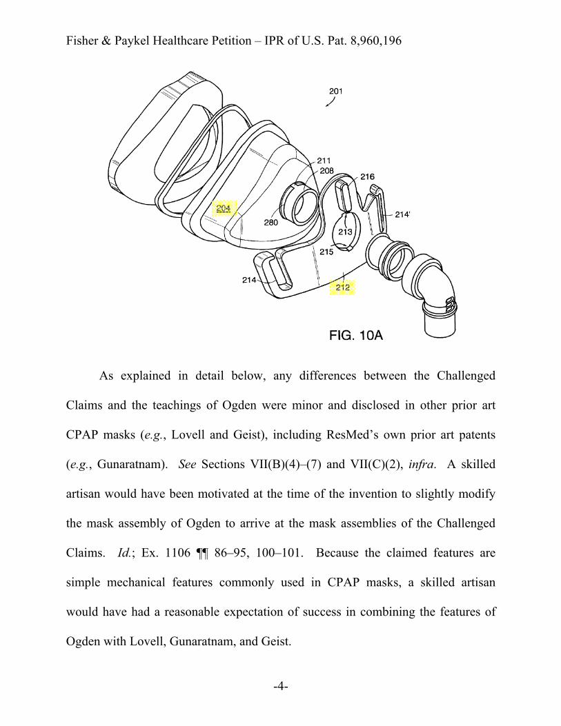
Lovell also discloses CPAP mask assemblies having (1) a shell 204 (first
frame) attached to the seal and (2) a headgear connector 212 (second frame) that
supports the first frame and is attached to the headgear, as shown in Fig. 10A of
Lovell:
shell 3 (first frame)
headgear connector 9 (second frame)
Fisher & Paykel Healthcare Petition – IPR of U.S. Pat. 8,960,196
-4-
As explained in detail below, any differences between the Challenged
Claims and the teachings of Ogden were minor and disclosed in other prior art
CPAP masks (e.g., Lovell and Geist), including ResMed’s own prior art patents
(e.g., Gunaratnam). See Sections VII(B)(4)–(7) and VII(C)(2), infra. A skilled
artisan would have been motivated at the time of the invention to slightly modify
the mask assembly of Ogden to arrive at the mask assemblies of the Challenged
Claims. Id.; Ex. 1106 ¶¶ 86–95, 100–101. Because the claimed features are
simple mechanical features commonly used in CPAP masks, a skilled artisan
would have had a reasonable expectation of success in combining the features of
Ogden with Lovell, Gunaratnam, and Geist.
Fisher & Paykel Healthcare Petition – IPR of U.S. Pat. 8,960,196
-5-
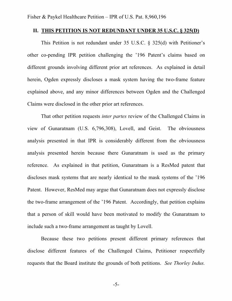
II. THIS PETITION IS NOT REDUNDANT UNDER 35 U.S.C. § 325(D)
This Petition is not redundant under 35 U.S.C. § 325(d) with Petitioner’s
other co-pending IPR petition challenging the ’196 Patent’s claims based on
different grounds involving different prior art references. As explained in detail
herein, Ogden expressly discloses a mask system having the two-frame feature
explained above, and any minor differences between Ogden and the Challenged
Claims were disclosed in the other prior art references.
That other petition requests inter partes review of the Challenged Claims in
view of Gunaratnam (U.S. 6,796,308), Lovell, and Geist. The obviousness
analysis presented in that IPR is considerably different from the obviousness
analysis presented herein because there Gunaratnam is used as the primary
reference. As explained in that petition, Gunaratnam is a ResMed patent that
discloses mask systems that are nearly identical to the mask systems of the ’196
Patent. However, ResMed may argue that Gunaratnam does not expressly disclose
the two-frame arrangement of the ’196 Patent. Accordingly, that petition explains
that a person of skill would have been motivated to modify the Gunaratnam to
include such a two-frame arrangement as taught by Lovell.
Because these two petitions present different primary references that
disclose different features of the Challenged Claims, Petitioner respectfully
requests that the Board institute the grounds of both petitions. See Thorley Indus.
Fisher & Paykel Healthcare Petition – IPR of U.S. Pat. 8,960,196
-6-
LLC V. Kolcraft Enterprises, Inc., IPR2016-00352, Paper 14 (Decision on
Institution of Inter Partes Review) at 20–21 (PTAB June 23, 2016); see also Ricoh
Corp., Xerox Corp., and Lexmark Intl. v. MPHJ Tech. LLC, IPR2014-00539, Paper
7 (Decision on Institution of Inter Partes Review) at 17 (PTAB August 25, 2014).
III. MANDATORY NOTICES UNDER 37 C.F.R. § 42.8(A)(1)
A. Real Party-In-Interest (37 C.F.R. § 42.8(b)(1))
Fisher & Paykel Healthcare Limited is the real party-in-interest. Fisher &
Paykel Healthcare Limited is publicly traded on the NZSX and ASX stock
exchanges under the symbol FPH. Petitioner Fisher & Paykel provides patients
with a broad range of innovative products and systems for use in the treatment of
obstructive sleep apnea (OSA) and sells its products in over 120 countries.
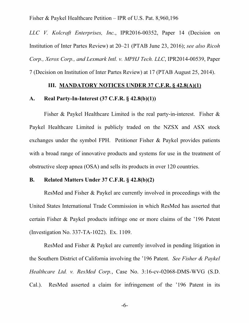
B. Related Matters Under 37 C.F.R. § 42.8(b)(2)
ResMed and Fisher & Paykel are currently involved in proceedings with the
United States International Trade Commission in which ResMed has asserted that
certain Fisher & Paykel products infringe one or more claims of the ’196 Patent
(Investigation No. 337-TA-1022). Ex. 1109.
ResMed and Fisher & Paykel are currently involved in pending litigation in
the Southern District of California involving the ’196 Patent. See Fisher & Paykel
Healthcare Ltd. v. ResMed Corp., Case No. 3:16-cv-02068-DMS-WVG (S.D.
Cal.). ResMed asserted a claim for infringement of the ’196 Patent in its

Fisher & Paykel Healthcare Petition – IPR of U.S. Pat. 8,960,196
-7-
counterclaims on September 7, 2016. Ex. 1110. The ’196 patent, which issued
after Fisher & Paykel launched its accused Simplus™ and Eson™ masks, does not
claim any inventive concept. Instead, it claims laundry lists of well-known mask
features in an attempt to cover Fisher & Paykel’s products. While the ’196 Patent
was filed on May 29, 2013, the Challenged Claims were not introduced until
September 30, 2014, after the launch of Fisher & Paykel’s Simplus™ and Eson™.
Fisher & Paykel has concurrently filed a second petition for inter partes
review of Claims 23–86 of the ’196 Patent that would affect, or be affected by, a
decision in this proceeding.
C. Lead and Back-up Counsel Under 37 C.F.R. § 42.8(b)(3)
Fisher & Paykel provides the following designation of counsel, all of whom
are included in Customer No. 20,995 identified in Fisher & Paykel’s Power of
Attorney.
Lead Counsel Back-up Counsel Brenton R. Babcock (Reg. No. 39,592) [email protected] Postal and Hand-Delivery Address: Knobbe, Martens, Olson & Bear, LLP 2040 Main St., 14th Floor Irvine, CA 92614 Telephone: (949) 760-0404 Facsimile: (949) 760-9502
Benjamin J. Everton (Reg. No. 60,659)[email protected] Postal and Hand-Delivery Address: Knobbe, Martens, Olson & Bear, LLP 2040 Main St., 14th Floor Irvine, CA 92614 Telephone: (949) 760-0404 Facsimile: (949) 760-9502

Fisher & Paykel Healthcare Petition – IPR of U.S. Pat. 8,960,196
-8-
D. Service Information Under 37 C.F.R. § 42.8(b)(4)
Service information for lead and back-up counsel is provided in the
designation of lead and back-up counsel above. Petitioner also consents to service
by email at the following address: [email protected].
IV. REQUIREMENTS FOR REVIEW UNDER 37 C.F.R. § 42.104
A. Grounds for Standing (37 C.F.R. § 42.104(a))
Petitioner hereby certifies that the ’196 Patent is available for inter partes
review and that Petitioner is not barred or estopped from requesting inter partes
review challenging the patent claims.
B. Statement of Relief Requested Under 37 C.F.R. §§ 42.104(b)(1)–(2)
1. Identification of Claims and Prior Art
Petitioner respectfully requests inter partes review of Claims 23–86 of the
’196 Patent, filed May 29, 2013, which is a continuation of U.S. Application No.
12/010,680, filed January 29, 2008, which claims priority benefit of U.S.
Provisional Application No. 60/898,108, filed January 30, 2007. Ex. 1101 at 1.
The earliest possible priority date of the ’196 Patent is January 30, 2007.
The Challenged Claims of the ’196 Patent would have been obvious in view
of the following prior art references:
x U.S. 5,662,101 (“Ogden”) (Ex. 1102), issued on September 2, 1997. Ex.
1102 at 1. Because Ogden issued more than one year before the earliest

Fisher & Paykel Healthcare Petition – IPR of U.S. Pat. 8,960,196
-9-
possible priority date of the ’196 Patent, it is prior art under 35 U.S.C. §
102(b).1
x U.S. 6,631,718 (“Lovell”) (Ex. 1103), issued on October 14, 2003. Ex. 1103
at 1. Because Lovell issued more than one year before the earliest possible
priority date of the ’196 Patent, it is prior art under 35 U.S.C. § 102(b).
x U.S. 6,796,308 (“Gunaratnam”) (Ex. 1104), issued on September 28, 2004.
Ex. 1104 at 1. Because Gunaratnam issued more than one year before the
earliest possible priority date of the ’196 Patent, it is prior art under 35
U.S.C. § 102(b).
x U.S. 7,353,827 (“Geist”) (Ex. 1105) was filed on September 1, 2004 and
issued on April 8, 2008. Ex. 1105 at 1. Because Geist is an issued patent
that was filed by another before the earliest possible priority date of the ’196
Patent, it is prior art under at least 35 U.S.C. § 102(e).
2. Grounds
Ground #1. Claims 23–78, 80–82, and 84–86 of the ’196 Patent would
have been obvious over Ogden in view of Lovell and Gunaratnam under 35 U.S.C.
§ 103.
1 Reference to 35 U.S.C. §§ 102 and 103 throughout this Petition are to the pre-
AIA versions of these statures, which are applicable to the ’196 Patent.
Fisher & Paykel Healthcare Petition – IPR of U.S. Pat. 8,960,196
-10-
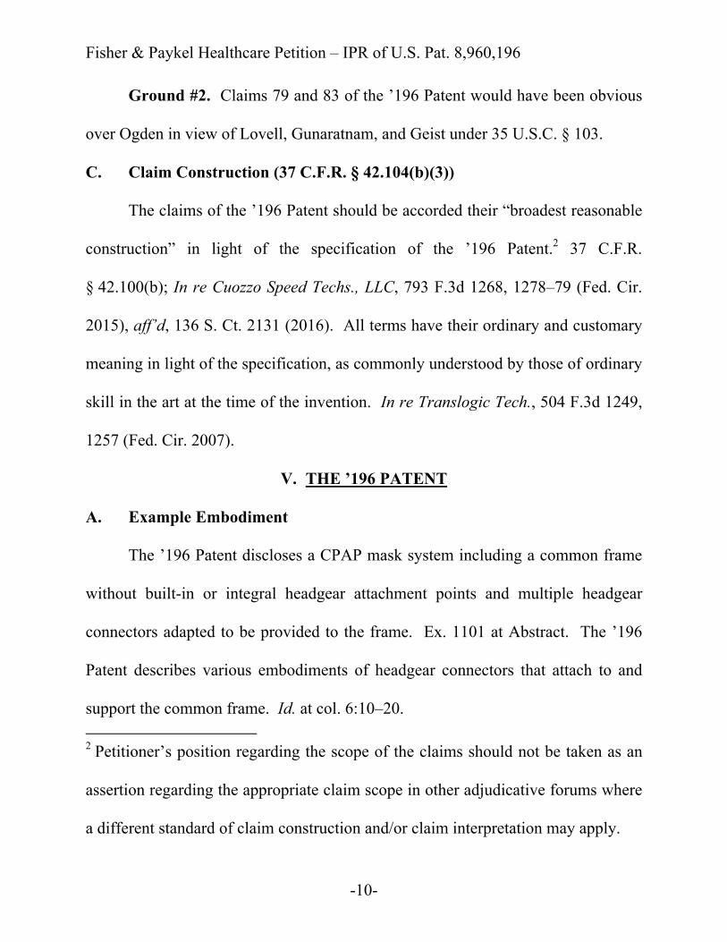
Ground #2. Claims 79 and 83 of the ’196 Patent would have been obvious
over Ogden in view of Lovell, Gunaratnam, and Geist under 35 U.S.C. § 103.
C. Claim Construction (37 C.F.R. § 42.104(b)(3))
The claims of the ’196 Patent should be accorded their “broadest reasonable
construction” in light of the specification of the ’196 Patent.2 37 C.F.R.
§ 42.100(b); In re Cuozzo Speed Techs., LLC, 793 F.3d 1268, 1278–79 (Fed. Cir.
2015), aff’d, 136 S. Ct. 2131 (2016). All terms have their ordinary and customary
meaning in light of the specification, as commonly understood by those of ordinary
skill in the art at the time of the invention. In re Translogic Tech., 504 F.3d 1249,
1257 (Fed. Cir. 2007).
V. THE ’196 PATENT
A. Example Embodiment
The ’196 Patent discloses a CPAP mask system including a common frame
without built-in or integral headgear attachment points and multiple headgear
connectors adapted to be provided to the frame. Ex. 1101 at Abstract. The ’196
Patent describes various embodiments of headgear connectors that attach to and
support the common frame. Id. at col. 6:10–20. 2 Petitioner’s position regarding the scope of the claims should not be taken as an
assertion regarding the appropriate claim scope in other adjudicative forums where
a different standard of claim construction and/or claim interpretation may apply.

Fisher & Paykel Healthcare Petition – IPR of U.S. Pat. 8,960,196
-11-
3
Figure 2B of the ’196 Patent (above right) illustrates a mask system that
includes a headgear connector 250(1) attached to a frame 220 and a forehead
support 272 adjustably mounted to the headgear connector 250(1). Id. at col. 7:3–
12. The headgear connector 250(1) includes an opening adapted to engage the
interfacing structure of the frame 220 with a snap-fit or other suitable attachment
mechanism. Id. at col. 6:32–38. “[T]he headgear connector 250(1) and forehead
support 272 are structured for use with headgear including a pair of lower side 3 Drawings of mask components circumscribed by dashed blue line, adapted from
commercial ResMed product literature, used for illustration purposes. The mask
frame 220 and headgear connector 250(1) are from the ’196 Patent.
Fisher & Paykel Healthcare Petition – IPR of U.S. Pat. 8,960,196
-12-
straps attached to respective clips 276 and a pair of upper side straps attached to
respective openings 273 on the forehead support 272.” Id. at col. 7:12–16.
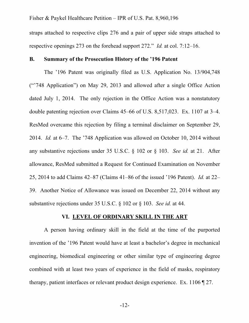
B. Summary of the Prosecution History of the ’196 Patent
The ’196 Patent was originally filed as U.S. Application No. 13/904,748
(“’748 Application”) on May 29, 2013 and allowed after a single Office Action
dated July 1, 2014. The only rejection in the Office Action was a nonstatutory
double patenting rejection over Claims 45–66 of U.S. 8,517,023. Ex. 1107 at 3–4.
ResMed overcame this rejection by filing a terminal disclaimer on September 29,
2014. Id. at 6–7. The ’748 Application was allowed on October 10, 2014 without
any substantive rejections under 35 U.S.C. § 102 or § 103. See id. at 21. After
allowance, ResMed submitted a Request for Continued Examination on November
25, 2014 to add Claims 42–87 (Claims 41–86 of the issued ’196 Patent). Id. at 22–
39. Another Notice of Allowance was issued on December 22, 2014 without any
substantive rejections under 35 U.S.C. § 102 or § 103. See id. at 44.
VI. LEVEL OF ORDINARY SKILL IN THE ART
A person having ordinary skill in the field at the time of the purported
invention of the ’196 Patent would have at least a bachelor’s degree in mechanical
engineering, biomedical engineering or other similar type of engineering degree
combined with at least two years of experience in the field of masks, respiratory
therapy, patient interfaces or relevant product design experience. Ex. 1106 ¶ 27.
Fisher & Paykel Healthcare Petition – IPR of U.S. Pat. 8,960,196
-13-
VII. THE CHALLENGED CLAIMS OF THE ’196 PATENT ARE
UNPATENTABLE
This Petition explains, in detail, why the Challenged Claims of the ’196
Patent are unpatentable. The Petition is supported by the declaration of Jason
Eaton, P.E. Ex. 1106. Mr. Eaton is a Principal Mechanical Engineer at MSA
Safety, a leading manufacturer of safety products. He has extensive academic and
industry experience in CPAP mask systems and design. Id. ¶¶ 3–8. His
declaration explains the basis for his conclusions that the Challenged Claims would
have been obvious. Id. ¶¶ 32–102.
A. Legal Standard for Obviousness
A claim is obvious “if the differences between the subject matter sought to
be patented and the prior art are such that the subject matter as a whole would have
been obvious at the time the invention was made to a person having ordinary skill
in the art to which said subject matter pertains.” 35 U.S.C. § 103. The
obviousness analysis includes an assessment of the Graham factors: (1) the scope
and content of the prior art; (2) any differences between the claims and the prior
art; (3) the level of ordinary skill in the art; and (4) any objective indicia of
nonobviousness. KSR Int’l v. Teleflex Inc., 550 U.S. 398, 406 (2007).

Fisher & Paykel Healthcare Petition – IPR of U.S. Pat. 8,960,196
-14-
B. Ground #1: Claims 23–78, 80–82, and 84–86 of the ’196 Patent would
have been obvious over Ogden in view of Lovell and Gunaratnam
1. Overview of Ogden (Ex. 1102)
Ogden was submitted during the prosecution of the ’196 Patent, but was not
cited by the Examiner. Ex. 1101 at 4.
Ogden describes facial mask assemblies for use in respiratory care and
therapy. Ex. 1102 at col. 1:5–12. As shown in Fig. 1 of Ogden (above), the mask
assembly 1 includes a rigid, cup-shaped shell 3 made of hard plastic and a soft seal
Fisher & Paykel Healthcare Petition – IPR of U.S. Pat. 8,960,196
-15-
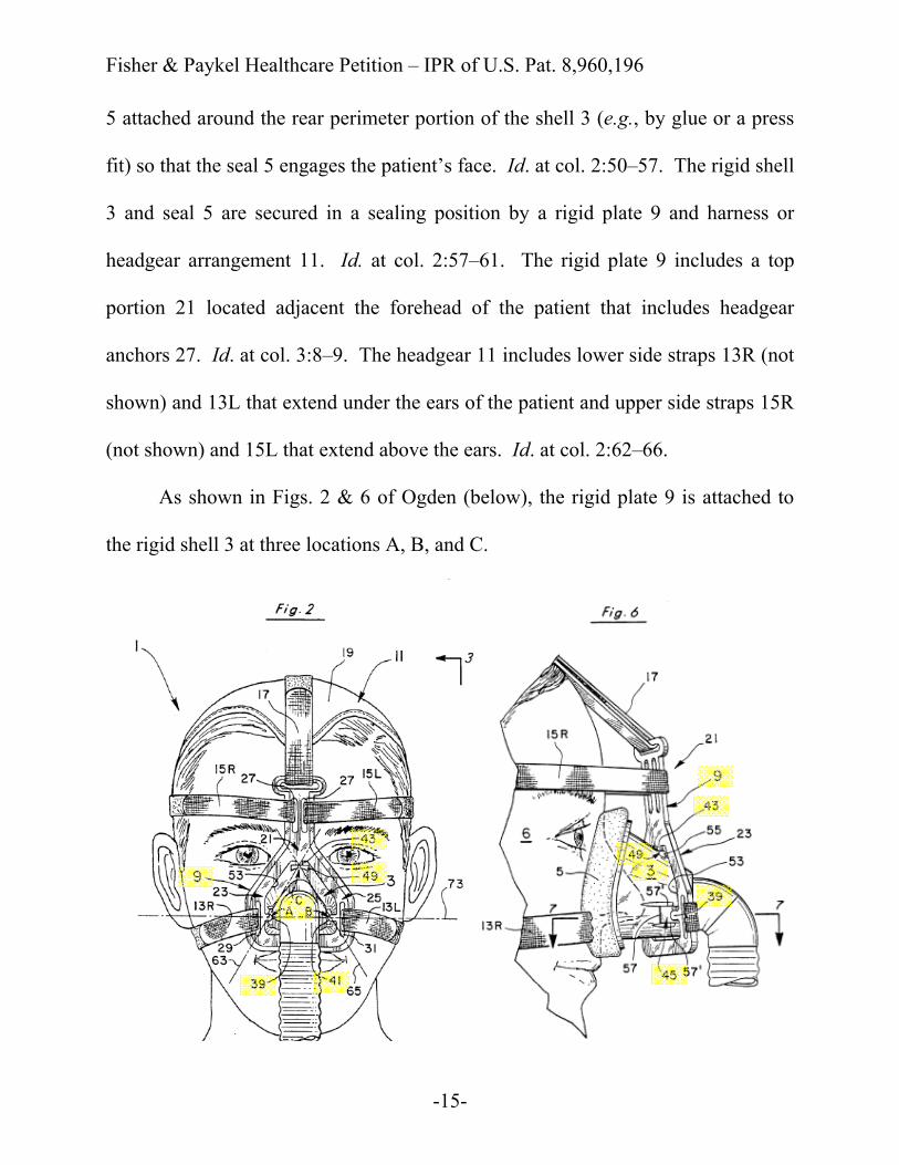
5 attached around the rear perimeter portion of the shell 3 (e.g., by glue or a press
fit) so that the seal 5 engages the patient’s face. Id. at col. 2:50–57. The rigid shell
3 and seal 5 are secured in a sealing position by a rigid plate 9 and harness or
headgear arrangement 11. Id. at col. 2:57–61. The rigid plate 9 includes a top
portion 21 located adjacent the forehead of the patient that includes headgear
anchors 27. Id. at col. 3:8–9. The headgear 11 includes lower side straps 13R (not
shown) and 13L that extend under the ears of the patient and upper side straps 15R
(not shown) and 15L that extend above the ears. Id. at col. 2:62–66.
As shown in Figs. 2 & 6 of Ogden (below), the rigid plate 9 is attached to
the rigid shell 3 at three locations A, B, and C.

Fisher & Paykel Healthcare Petition – IPR of U.S. Pat. 8,960,196
-16-
The rigid plate 9 includes detents 39, 41, and 43 that are received into
channels 45, 47 (not shown), and 49 on the rigid shell 3. Id. at col. 3:25–34.
Ogden discloses that the “detent-channel 43, 49 at the top of the shell 3 at the third
location C is preferably dimensioned to snap together to hold or maintain the rigid
plate 9 on the rigid shell 3.” Id. at col. 5:15–17.
2. Overview of Lovell (Ex. 1103)
Lovell was submitted during the prosecution of the ’196 Patent, but was not
cited by the Examiner. Ex. 1101 at 5. Lovell generally relates to CPAP masks.
Ex. 1103 at col. 1:5–8. The masks include a “seal [] disposed along a perimeter of
the shell so as to form a chamber within the shell when the mask is donned by a
user.” Id. at Abstract, col. 2:56–58.
Fisher & Paykel Healthcare Petition – IPR of U.S. Pat. 8,960,196
-17-
As shown in Fig. 10A of Lovell (above), the nasal mask 201 has a retainer
212 that is contoured to match the external curvature of the contoured shell 204
and is coupled to an inlet 208 on the front face of the frame 204. Id. at col. 9:43–
46. The inlet 208 is adapted to connect with a conduit elbow via a swivel
connector. Id. at col. 5:20–22, 9:34–36, 9:57–59. The contoured shell 204 has
depressed annular regions 280 (extending between tabs 211 and 211′) on the
inlet 208 that mate with the tabs (extending between slots 213, 215) formed in the
retainer 212 to form an interference fit. Id. at col. 9:46–64.
3. Overview of Gunaratnam (Ex. 1104)
Gunaratnam was submitted during the prosecution of the ’196 Patent, but
was not cited by the Examiner. Ex. 1101 at 5. Gunaratnam generally relates to
masks “suitable for the delivery of breathable gases to a patient for the treatment of
sleep disordered breathing.” Ex. 1104 at col. 1:21–25.
Fisher & Paykel Healthcare Petition – IPR of U.S. Pat. 8,960,196
-18-
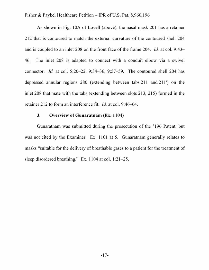
Fig. 5c of Gunaratnam (above) illustrates a T-shaped headgear connector.
Id. at col. 4:46–48. The headgear connector 160/162 has strap connection points
630 to connect the mask to headgear and a forehead support 162. Id. at col. 4:32–
33. The strap connection points 630 can connect to the headgear via connectors
200. Id. at col. 4:34. The frame 160 is a substantially rigid shell of polycarbonate
and incorporates a gas inlet aperture. Id. at col. 4:22–26.
4. Potential Differences Between the Prior Art and Claims 23–40
and Reasons to Combine
As detailed in the claim charts below, Ogden discloses nearly all of the
limitations of Claim 23 and its dependent claims.
Fisher & Paykel Healthcare Petition – IPR of U.S. Pat. 8,960,196
-19-
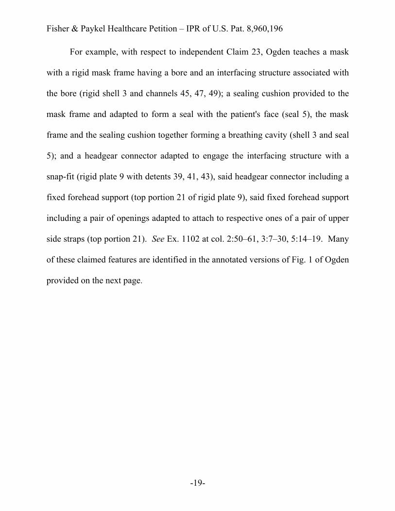
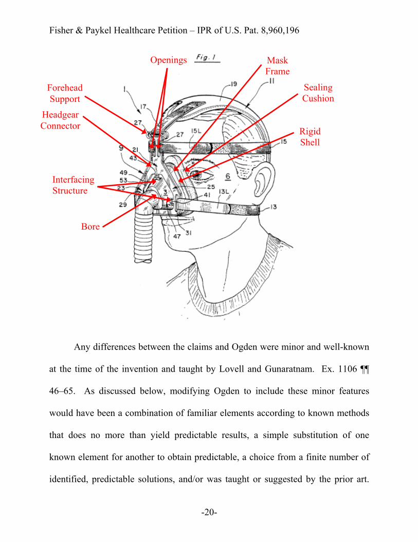
For example, with respect to independent Claim 23, Ogden teaches a mask
with a rigid mask frame having a bore and an interfacing structure associated with
the bore (rigid shell 3 and channels 45, 47, 49); a sealing cushion provided to the
mask frame and adapted to form a seal with the patient's face (seal 5), the mask
frame and the sealing cushion together forming a breathing cavity (shell 3 and seal
5); and a headgear connector adapted to engage the interfacing structure with a
snap-fit (rigid plate 9 with detents 39, 41, 43), said headgear connector including a
fixed forehead support (top portion 21 of rigid plate 9), said fixed forehead support
including a pair of openings adapted to attach to respective ones of a pair of upper
side straps (top portion 21). See Ex. 1102 at col. 2:50–61, 3:7–30, 5:14–19. Many
of these claimed features are identified in the annotated versions of Fig. 1 of Ogden
provided on the next page.
Fisher & Paykel Healthcare Petition – IPR of U.S. Pat. 8,960,196
-20-
Any differences between the claims and Ogden were minor and well-known
at the time of the invention and taught by Lovell and Gunaratnam. Ex. 1106 ¶¶
46–65. As discussed below, modifying Ogden to include these minor features
would have been a combination of familiar elements according to known methods
that does no more than yield predictable results, a simple substitution of one
known element for another to obtain predictable, a choice from a finite number of
identified, predictable solutions, and/or was taught or suggested by the prior art.
Forehead Support
Openings
Headgear Connector
Sealing Cushion
Bore
Interfacing Structure
Rigid Shell
Mask Frame
Fisher & Paykel Healthcare Petition – IPR of U.S. Pat. 8,960,196
-21-
See KSR, 550 U.S. at 416–20. Because Ogden, Lovell, and Gunaratnam all teach
structurally similar CPAP masks for the treatment of sleep disordered breathing,
the features taught in Lovell and Gunaratnam would have been readily compatible
with and easily incorporated into the mask of Ogden with a reasonable expectation
of success. Ex. 1106 ¶ 86.
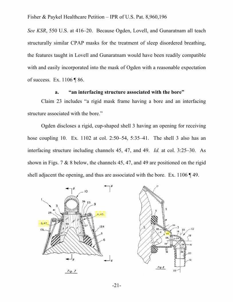
a. “an interfacing structure associated with the bore”
Claim 23 includes “a rigid mask frame having a bore and an interfacing
structure associated with the bore.”
Ogden discloses a rigid, cup-shaped shell 3 having an opening for receiving
hose coupling 10. Ex. 1102 at col. 2:50–54, 5:35–41. The shell 3 also has an
interfacing structure including channels 45, 47, and 49. Id. at col. 3:25–30. As
shown in Figs. 7 & 8 below, the channels 45, 47, and 49 are positioned on the rigid
shell adjacent the opening, and thus are associated with the bore. Ex. 1106 ¶ 49.

Fisher & Paykel Healthcare Petition – IPR of U.S. Pat. 8,960,196
-22-
However, to the extent the “interfacing structure associated with the bore” is
interpreted narrowly to mean an interfacing structure positioned directly at the
bore, such interfacing structure was known in the art prior to the ’196 Patent. Id. ¶
50. For example, Lovell discloses a frame 204 having an annular bore 208 on a
front face of the frame 204. Ex. 1103 at col. 9:43–44. The bore 208 includes, and
is thus associated with, an interfacing structure (depressed annular regions 280
extending between two tabs 211, 211') that mates with the headgear connector 212.
Id. at col. 9:46–64; Ex. 1106 ¶ 50.
A person of skill in the art at the time of the invention would have
recognized that positioning the interfacing structure at the bore of the mask frame,
as taught by Lovell, would allow the headgear connector to be connected to the
Fisher & Paykel Healthcare Petition – IPR of U.S. Pat. 8,960,196
-23-
mask frame near the elbow connection and could better secure and seal the elbow
to the mask frame. Ex. 1106 ¶ 89. Modifying the mask of Ogden to include the
frame features of Lovell would have been a combination of familiar elements
according to known methods that does no more than yield predictable results. See
KSR, 550 U.S. at 416.
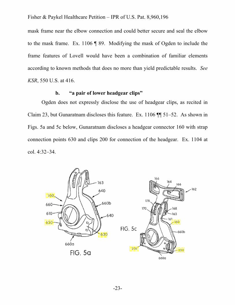
b. “a pair of lower headgear clips”
Ogden does not expressly disclose the use of headgear clips, as recited in
Claim 23, but Gunaratnam discloses this feature. Ex. 1106 ¶¶ 51–52. As shown in
Figs. 5a and 5c below, Gunaratnam discloses a headgear connector 160 with strap
connection points 630 and clips 200 for connection of the headgear. Ex. 1104 at
col. 4:32–34.
Fisher & Paykel Healthcare Petition – IPR of U.S. Pat. 8,960,196
-24-
A person of skill in the art at the time of the invention would have been
motivated to modify the headgear connector of Ogden to include a pair of lower
headgear clips, as taught by Gunaratnam. Ex. 1106 ¶ 91. Such clips were
commonly used to facilitate removal of the headgear straps from the headgear
connector during cleaning and reattachment of the headgear straps without
requiring any strap length adjustment. Id. Headgear clips would also allow the
user to secure the headgear to the mask after the mask is properly positioned on the
user’s face. Id. Such a modification would have been a mere substitution of one
known feature for another to obtain predictable results. See KSR, 550 U.S. at 416.
Fisher & Paykel Healthcare Petition – IPR of U.S. Pat. 8,960,196
-25-
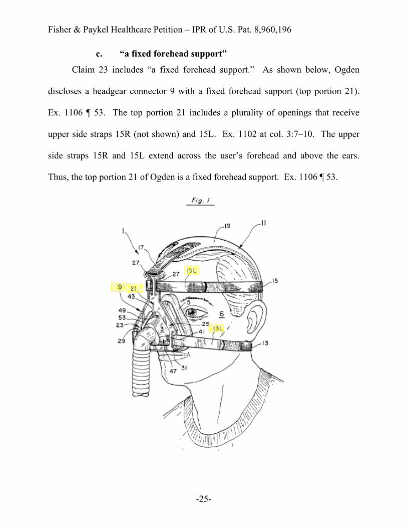
c. “a fixed forehead support”
Claim 23 includes “a fixed forehead support.” As shown below, Ogden
discloses a headgear connector 9 with a fixed forehead support (top portion 21).
Ex. 1106 ¶ 53. The top portion 21 includes a plurality of openings that receive
upper side straps 15R (not shown) and 15L. Ex. 1102 at col. 3:7–10. The upper
side straps 15R and 15L extend across the user’s forehead and above the ears.
Thus, the top portion 21 of Ogden is a fixed forehead support. Ex. 1106 ¶ 53.

Fisher & Paykel Healthcare Petition – IPR of U.S. Pat. 8,960,196
-26-
To the extent “fixed forehead support” is interpreted narrowly to require that
the forehead support directly contact the user’s forehead, such forehead supports
were well-known in the prior art. Id. ¶ 54. For example, as shown in Fig. 5c of
Gunaratnam, masks were known to include forehead supports (element 162). Ex.
1104 at col. 1:29–35.
Modifying the forehead support of Ogden to contour toward and contact the
user’s forehead, as taught by Gunaratnam, would have been a combination of
familiar elements according to known methods that does no more than yield
predictable results. See KSR, 550 U.S. at 416. A person of skill in the art would
have recognized that the contoured, fixed forehead support would provide greater
stability, provide a greater field of view around the forehead support, and provide a
more aesthetic streamlined interface. Ex. 1106 ¶¶ 55, 92.
Fisher & Paykel Healthcare Petition – IPR of U.S. Pat. 8,960,196
-27-
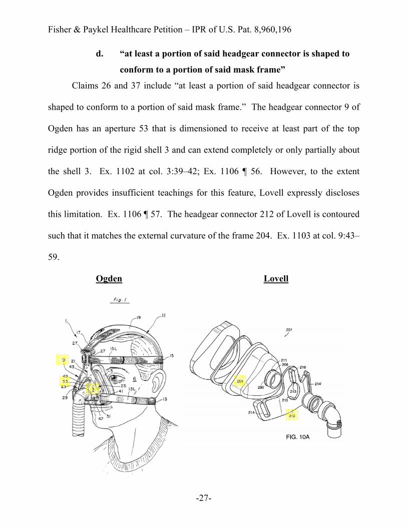
d. “at least a portion of said headgear connector is shaped to
conform to a portion of said mask frame”
Claims 26 and 37 include “at least a portion of said headgear connector is
shaped to conform to a portion of said mask frame.” The headgear connector 9 of
Ogden has an aperture 53 that is dimensioned to receive at least part of the top
ridge portion of the rigid shell 3 and can extend completely or only partially about
the shell 3. Ex. 1102 at col. 3:39–42; Ex. 1106 ¶ 56. However, to the extent
Ogden provides insufficient teachings for this feature, Lovell expressly discloses
this limitation. Ex. 1106 ¶ 57. The headgear connector 212 of Lovell is contoured
such that it matches the external curvature of the frame 204. Ex. 1103 at col. 9:43–
59.
Ogden Lovell

Fisher & Paykel Healthcare Petition – IPR of U.S. Pat. 8,960,196
-28-
A person of skill in the art at the time of the invention would have been
motivated to shape the headgear connector of Ogden to conform to a portion of the
mask frame, as taught by Lovell, to decrease the profile of the mask. Ex. 1106 ¶
92. The lower profile would make the mask more visually appealing, improve the
user’s field-of-view, and reduce the likelihood of the mask coming into contact
with other objects (e.g., pillows or bedding). Id. Such a modification would have
been a combination of familiar elements according to known methods that does no
more than yield predictable results. See KSR, 550 U.S. at 416.
e. “wherein the headgear connector is removably attachable to
the mask frame”
Claims 28 and 37 include “the headgear connector is removably attachable
to the mask frame.”

Fisher & Paykel Healthcare Petition – IPR of U.S. Pat. 8,960,196
-29-
The mask assembly of Ogden is assembled by slightly stressing the detent
43 on the headgear connector 9 over the front wall 55 to position the detent 43 in
the channel 49 of the frame 3 (see Fig. 8 below). Ex. 1102 at col. 5:14–22. A
skilled artisan at the time of the invention would appreciate that the headgear
connector 9 could be removed from the shell 3 by flexing the detent 43 back over
the front wall 55 and out of the channel 49. Ex. 1106 ¶ 58.
However, to the extent Ogden somehow provides insufficient teachings for
this limitation, such removable attachments were well-known in CPAP masks, as

Fisher & Paykel Healthcare Petition – IPR of U.S. Pat. 8,960,196
-30-
disclosed by Gunaratnam. Ex. 1106 ¶ 59. Gunaratnam discloses that the frame
800 can be removed from headgear connector 160 to clean the mask assembly or
replace the cushion by forcing the detents 820 outwardly against their natural
resilience to release the detents from the recesses 660 and ride over the outer edge
of flange 640. Ex. 1104 at col. 5:34–43.
Based on the teachings in the prior art, a person of skill in the art at the time
of the invention would have been motivated to provide a headgear connector that is
removably attachable to a mask frame to allow for easy removal of the mask frame
and cushion from the mask assembly for cleaning or replacement. Ex. 1106 ¶ 87;
Ex. 1104 at col. 5:34–43; Ex. 1105 at col. 2:6–16; see also KSR, 550 U.S. at 419.
f. “the mask frame and the headgear connector are not
movable relative to one another”
Claims 29 and 37 recite, “when said mask frame and said headgear
connector are attached, the mask frame and the headgear connector are not

Fisher & Paykel Healthcare Petition – IPR of U.S. Pat. 8,960,196
-31-
movable relative to one another.” Ogden discloses that “previous mask assemblies
of similar construction to the present invention fixedly mounted the rigid plate 9' to
their shell 3'.” Ex. 1102 at col. 3:57–59. Thus, Ogden acknowledges that it was
well-known to attach the mask frame and headgear connector in a non-movable
manner. Ex. 1106 ¶¶ 60–61. The mask assemblies of Lovell also include this
limitation. Id. ¶ 62. Lovell discloses that “the retainer 212 is properly retained by
the cooperation of the tabs 211, 211′ (not shown), the slots 213, 215, and the
depressed annular region 280 when fully seated against the shell 204.” Id.; Ex.
1103 at col. 9:59–64.
A person of skill in the art at the time of the invention would have been
motivated to modify the frame of Ogden to be not movable relative to the headgear
connector, as taught by Lovell. Ex. 1106 ¶ 88. Such a person would have known

Fisher & Paykel Healthcare Petition – IPR of U.S. Pat. 8,960,196
-32-
that, in Ogden, the headgear connector moves relative to the mask frame, so it is
not possible to control the pressure along the perimeter of the mask. Id. A person
of skill would have recognized that modifying Ogden so that the headgear
connector is not movable relative to the frame would provide more stability
between the headgear connector and the mask frame. Id. Because users have
unique and differing facial geometries, it is advantageous to be able to adjust the
headgear and headgear connector to apply more or less pressure along the
perimeter of the mask to maintain a comfortable and effective seal against the face.
Id. Such a modification would have been a combination of familiar elements
according to known methods that does no more than yield predictable results. See
KSR, 550 U.S. at 416.

Fisher & Paykel Healthcare Petition – IPR of U.S. Pat. 8,960,196
-33-
g. “a vent assembly for gas washout”
Ogden does not expressly disclose a vent assembly, but Lovell and
Gunaratnam both disclose this feature of Claims 31 and 37. Ex. 1106 ¶¶ 63– 64.
Lovell discloses apertures 17 on the elbow conduit “to allow the release of gases
exhaled by the user, as well as preferentially vent the chamber 80 upon
overpressurization.” Ex. 1103 at col. 5:38–41. Gunaratnam discloses an air vent
assembly 940 positioned on the frame 160. Ex. 1104 at col. 6:25–30.
A person of skill in the art would have recognized the need for a vent
assembly, as taught by Lovell and Gunaratnam. Ex. 1106 ¶ 93; see also KSR, 550
U.S. at 419. Such vent assemblies were frequently included in mask assemblies to
allow for the release of gases exhaled by the user. Ex. 1106 ¶ 93; Ex. 1103 at col.
5:36–41.
Fisher & Paykel Healthcare Petition – IPR of U.S. Pat. 8,960,196
-34-
h. “wherein said headgear connector and said mask frame are
constructed of polycarbonate”
Claim 36 recites, “said headgear connector and said mask frame are
constructed of polycarbonate.” Ogden discloses that the frame 3 and the headgear
connector 9 are made of hard plastic. Ex. 1102 at col. 2:50–54, 3:25–26. Ogden
does not disclose a specific type of plastic, but it was very common to use
polycarbonate, as taught by Gunaratnam. Ex. 1106 ¶ 65. Gunaratnam discloses
that the frame and headgear connector are constructed from polycarbonate or
similar transparent plastics material. Ex. 1104 at col. 4:22–26, 5:34–35.
A person of skill in the art would have known to make the frame of Ogden
out of polycarbonate, as taught by Gunaratnam. Ex. 1106 ¶ 94. It was well-known
at the time of the invention to use polycarbonate which provides a high degree of
clarity, which makes a mask visually less obtrusive to the patient and allows
clinicians to monitor condensation in the mask and the user’s skin tone. Id.
Polycarbonate also provides good mechanical properties of strength, rigidity, and
toughness, and it can also be cleaned, disinfected, and/or sterilized by most
commonly used methods. Id. Such a modification would have been a combination
of familiar elements according to known methods that does no more than yield
predictable results. See KSR, 550 U.S. at 416.
Fisher & Paykel Healthcare Petition – IPR of U.S. Pat. 8,960,196
-35-
5. Potential Differences Between the Prior Art and Claims 41–56
and Reasons to Combine
As detailed in the claim charts below, Ogden discloses nearly all of the
limitations of Claim 41 and its dependent claims. Any minor differences between
these claims and Ogden were taught by Lovell and Gunaratnam. Ex. 1106 ¶¶ 66–
71.
Ogden teaches nearly all of the features of Claim 41, including a “a one-
piece rigid mask frame having a bore and an interfacing structure at least partly
surrounding the bore,” “the attachment structure being adapted to engage the
interfacing structure of the rigid mask frame to removably connect the headgear
connector to the rigid mask frame,” and “a fixed forehead support.” Id. ¶¶ 67–68.
Ogden also teaches “at least a portion of said headgear connector is shaped to
conform to a portion of said rigid mask frame,” as recited by Claim 44, and
“wherein when said rigid mask frame and said headgear connector are attached, the
rigid mask frame and the headgear connector are not movable relative to one
another,” as recited by Claim 45. Id. ¶ 68. However, to the extent Ogden
somehow provides insufficient teachings for these features, Gunaratnam and
Lovell teach these limitations as described above with respect to Claims 23, 26, 28,
29, and 37 (see Sections VII(B)(4)(a) and (c)–(f)).
Fisher & Paykel Healthcare Petition – IPR of U.S. Pat. 8,960,196
-36-
Further, Ogden does not expressly disclose “a vent assembly for gas
washout,” as recited by Claims 47 and 53, “said headgear connector and said rigid
mask frame are constructed of polycarbonate,” as recited by Claim 52, or “a pair of
lower headgear clips,” as recited by Claim 54. However, as described above in
Sections VII(B)(4)(b) and (g)–(h), Gunaratnam teaches these limitations.
Additional features beyond those discussed above are described below.
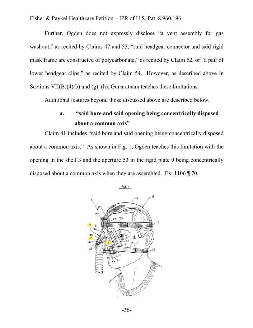
a. “said bore and said opening being concentrically disposed
about a common axis”
Claim 41 includes “said bore and said opening being concentrically disposed
about a common axis.” As shown in Fig. 1, Ogden teaches this limitation with the
opening in the shell 3 and the aperture 53 in the rigid plate 9 being concentrically
disposed about a common axis when they are assembled. Ex. 1106 ¶ 70.

Fisher & Paykel Healthcare Petition – IPR of U.S. Pat. 8,960,196
-37-
However, to the extent the term “concentrically disposed” is narrowly
interpreted to require an annular bore and an annular opening being concentrically
disposed about a common axis, Lovell teaches such a configuration. Id. ¶ 71. As
shown in Fig. 10A of Lovell (below), the annular inlet 208 of the frame 204 and
the annular opening in the headgear connector 212 are concentrically disposed
about a common axis, when assembled. Ex. 1103 at col. 9:57–64.
A person of skill in the art at the time of the invention would have seen
benefit in including an annular bore on the frame and an annular opening on the
headgear connector that are concentrically disposed about a common axis because
annular features on mating parts would have been simpler to design, specify, and
manufacture. Ex. 1106 ¶ 90. Such a modification would have been a combination
Fisher & Paykel Healthcare Petition – IPR of U.S. Pat. 8,960,196
-38-
of familiar elements according to known methods that does no more than yield
predictable results. See KSR, 550 U.S. at 416.
6. Potential Differences Between the Prior Art and Claims 57–72
and Reasons to Combine
As detailed in the claim charts below, Ogden discloses nearly all of the
limitations of Claim 57 and its dependent claims. Any minor differences were
well-known at the time of the invention and are taught by Lovell and Gunaratnam.
Ex. 1106 ¶¶ 72–81.
Ogden teaches nearly all of the limitations of Claim 57, including “said
opening and said bore are concentrically disposed about a common axis,” “a
forehead support,” and “the rigid mask frame and the headgear connector are not
movable relative to one another.” Id. ¶¶ 73–74. Ogden also teaches “an inner
surface of said headgear connector is shaped to conform to an outer surface of said
rigid mask frame,” as recited by Claim 60. However, to the extent Ogden
somehow provides insufficient teachings for these features, Gunaratnam and
Lovell teach these limitations as described above with respect to Claims 23, 26, 29,
37, and 41 (see Sections VII(B)(4)(c), (d), and (f) and VII(B)(5)(a)).
Further, Ogden does not expressly disclose “a vent assembly for gas
washout,” as recited by Claim 63 or “said headgear connector and said rigid mask
frame are constructed of polycarbonate,” as recited by Claim 68. However, as
Fisher & Paykel Healthcare Petition – IPR of U.S. Pat. 8,960,196
-39-
described above in Sections VII(B)(4)(g)–(h), Gunaratnam teaches these
limitations.
Additional features beyond those discussed above are described below.
a. “a rigid mask frame having a bore and a cylindrical
projection extending around the bore . . . the attachment
structure removably attached to the cylindrical projection
of the rigid mask frame with a snap-fit such that when said
cylindrical projection and said attachment structure are
attached, the rigid mask frame and the headgear connector
are not movable relative to one another”
Ogden does not expressly disclose a rigid mask frame having a bore and a
cylindrical projection around the bore, but Lovell discloses this limitation of Claim
57. Ex. 1106 ¶¶ 77–79.
As shown in Fig. 10A of Lovell (see next page), the frame 204 has an
annular or cylindrical inlet 208. Ex. 1103 at col. 9:57–59. The cylindrical inlet
208 has depressed annular regions 280 that mate with the tabs extending between
slots 213, 215 on an opening of the headgear connector 212 to form a snap fit. Id.
at col. 9:59–64; Ex. 1106 ¶¶ 77–79.

Fisher & Paykel Healthcare Petition – IPR of U.S. Pat. 8,960,196
-40-
The ’196 Patent recognizes that a snap-fit results when the frame 20 receives
a plurality of tabs 144 on the headgear connector 150(1). Ex. 1101 at col. 5:1–2.
Tabs
Depressed Regions
Fisher & Paykel Healthcare Petition – IPR of U.S. Pat. 8,960,196
-41-
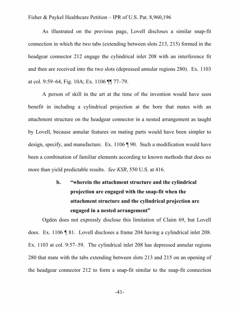
As illustrated on the previous page, Lovell discloses a similar snap-fit
connection in which the two tabs (extending between slots 213, 215) formed in the
headgear connector 212 engage the cylindrical inlet 208 with an interference fit
and then are received into the two slots (depressed annular regions 280). Ex. 1103
at col. 9:59–64, Fig. 10A; Ex. 1106 ¶¶ 77–79.
A person of skill in the art at the time of the invention would have seen
benefit in including a cylindrical projection at the bore that mates with an
attachment structure on the headgear connector in a nested arrangement as taught
by Lovell, because annular features on mating parts would have been simpler to
design, specify, and manufacture. Ex. 1106 ¶ 90. Such a modification would have
been a combination of familiar elements according to known methods that does no
more than yield predictable results. See KSR, 550 U.S. at 416.
b. “wherein the attachment structure and the cylindrical
projection are engaged with the snap-fit when the
attachment structure and the cylindrical projection are
engaged in a nested arrangement”
Ogden does not expressly disclose this limitation of Claim 69, but Lovell
does. Ex. 1106 ¶ 81. Lovell discloses a frame 204 having a cylindrical inlet 208.
Ex. 1103 at col. 9:57–59. The cylindrical inlet 208 has depressed annular regions
280 that mate with the tabs extending between slots 213 and 215 on an opening of
the headgear connector 212 to form a snap-fit similar to the snap-fit connection
Fisher & Paykel Healthcare Petition – IPR of U.S. Pat. 8,960,196
-42-
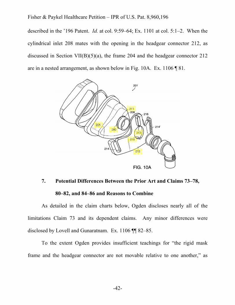
described in the ’196 Patent. Id. at col. 9:59–64; Ex. 1101 at col. 5:1–2. When the
cylindrical inlet 208 mates with the opening in the headgear connector 212, as
discussed in Section VII(B)(5)(a), the frame 204 and the headgear connector 212
are in a nested arrangement, as shown below in Fig. 10A. Ex. 1106 ¶ 81.
7. Potential Differences Between the Prior Art and Claims 73–78,
80–82, and 84–86 and Reasons to Combine
As detailed in the claim charts below, Ogden discloses nearly all of the
limitations Claim 73 and its dependent claims. Any minor differences were
disclosed by Lovell and Gunaratnam. Ex. 1106 ¶¶ 82–85.
To the extent Ogden provides insufficient teachings for “the rigid mask
frame and the headgear connector are not movable relative to one another,” as

Fisher & Paykel Healthcare Petition – IPR of U.S. Pat. 8,960,196
-43-
recited by Claim 77, teaches this limitation as described above with respect to
Claims 29 and 37 (see Section VII(B)(4)(f)).
Ogden does not expressly disclose “said headgear connector and said rigid
mask frame are constructed of polycarbonate,” as recited by Claim 82. However,
as described above in Section VII(B)(4)(h), Gunaratnam teaches this limitation.
C. Ground #2: Claims 79 and 83 of the ’196 Patent would have been obvious over Ogden in view of Lovell, Gunaratnam, and Geist
1. Overview of Geist (Ex. 1105)
Geist was submitted during the prosecution of the ’196 Patent, but was not
specifically cited by the examiner. Ex. 1101 at 6.
Geist relates to CPAP masks “particularly useful for supplying pressurized
breathing gas, such as oxygen, to a person in the treatment of obstructive sleep
apnea.” Ex. 1105 at col. 1:9–14. Fig. 10 of Geist (below) is a bottom perspective
view of a mask shell 12 with vent holes 60 on the bottom of the shell. Id. at col.
3:4–6, 5:11–14.
Fisher & Paykel Healthcare Petition – IPR of U.S. Pat. 8,960,196
-44-
2. Potential Differences Between the Prior Art and Claims 79 and 83
and Reasons to Combine
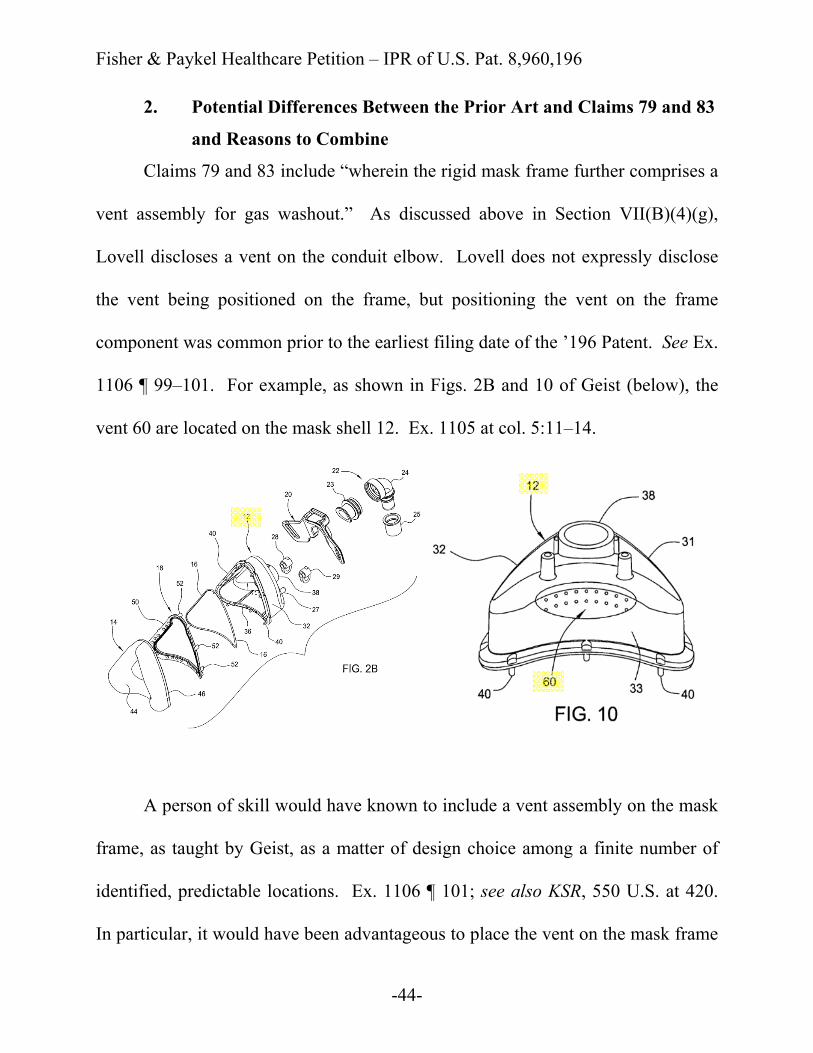
Claims 79 and 83 include “wherein the rigid mask frame further comprises a
vent assembly for gas washout.” As discussed above in Section VII(B)(4)(g),
Lovell discloses a vent on the conduit elbow. Lovell does not expressly disclose
the vent being positioned on the frame, but positioning the vent on the frame
component was common prior to the earliest filing date of the ’196 Patent. See Ex.
1106 ¶ 99–101. For example, as shown in Figs. 2B and 10 of Geist (below), the
vent 60 are located on the mask shell 12. Ex. 1105 at col. 5:11–14.
A person of skill would have known to include a vent assembly on the mask
frame, as taught by Geist, as a matter of design choice among a finite number of
identified, predictable locations. Ex. 1106 ¶ 101; see also KSR, 550 U.S. at 420.
In particular, it would have been advantageous to place the vent on the mask frame

Fisher & Paykel Healthcare Petition – IPR of U.S. Pat. 8,960,196
-45-
instead of the elbow so that the vent is in direct fluid communication with the
breathing chamber. Ex. 1106 ¶ 101. This would reduce “dead space” which is the
volume in which expired air is trapped between the user’s nose and an upstream
vent. Id. Because Ogden, Lovell, Gunaratnam, and Geist all relate to structurally
similar CPAP masks, the features of Lovell, Gunaratnam, and Geist would have
been readily compatible and easily incorporated into the mask of Ogden with a
reasonable expectation of success. Id. ¶ 100.

Fisher & Paykel Healthcare Petition – IPR of U.S. Pat. 8,960,196
-46-
VIII. CLAIM CHARTS
’196 Patent Prior Art 23. A mask for delivering breathable gas to a patient at positive pressure to treat sleep disordered breathing, the mask comprising:
Ogden: “Typically, the mask is sized to fit over the patient's nose (i.e., nasal mask) or nose and mouth (i.e., full face mask).” Ex. 1102 at col. 1:9–12. “The flexible hose 12 (which can be connected to a respiratory device such as a ventilator or continuous positive airway pressure (CPAP) device) is then slid over the rigid tube 20.” Id. at col. 5:41–44.
a rigid mask frame having a bore and an interfacing structure associated with the bore, said mask frame having no built-in or integral headgear attachment points;
Ogden: “[T]he facial mask assembly 1 of the present invention includes a rigid, cup-shaped shell 3 made of hard plastic and dimensioned to surround and enclose the patient's nose 2 and nares 4.” Ex. 1102 at col. 2:50–54. “The rigid plate 9 as best seen in FIGS. 2 and 3 is mounted to the rigid shell 3 at at least three locations A, B, and C by detents 39, 41, and 43 respectively received in channels 45, 47, and 49 (see also FIGS. 1, 6, and 7).” Id. at col. 3:26–30.
Fisher & Paykel Healthcare Petition – IPR of U.S. Pat. 8,960,196
-47-
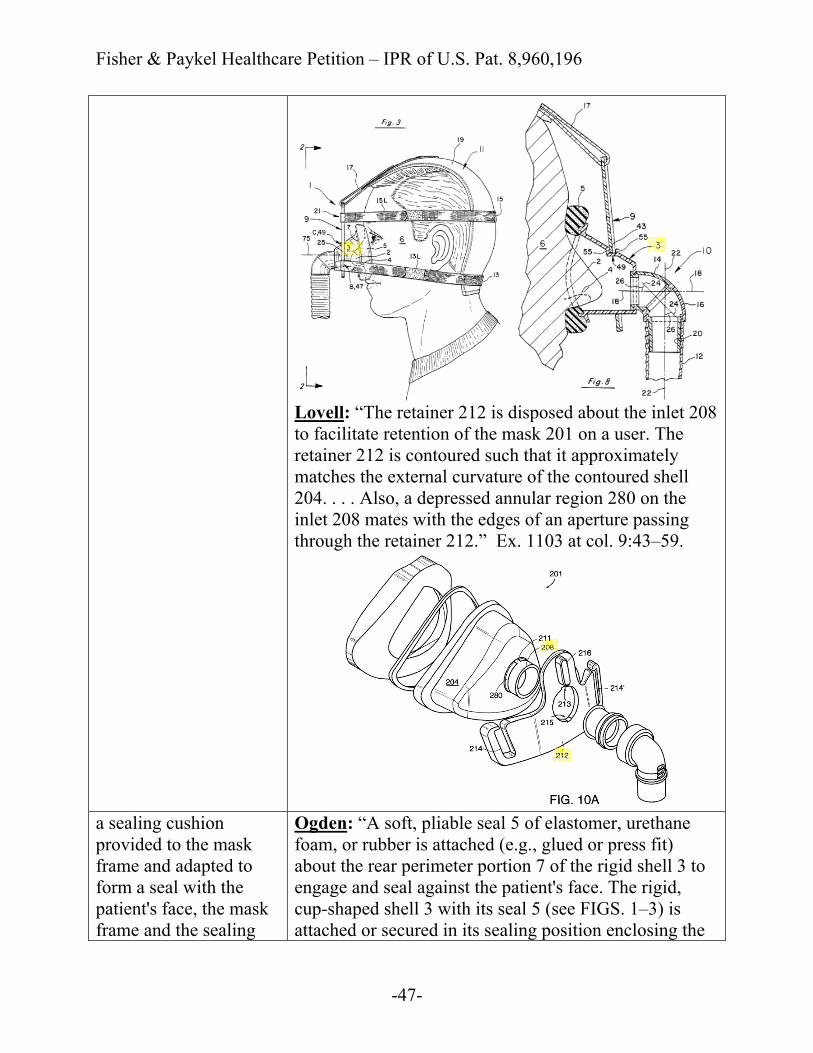
Lovell: “The retainer 212 is disposed about the inlet 208 to facilitate retention of the mask 201 on a user. The retainer 212 is contoured such that it approximately matches the external curvature of the contoured shell 204. . . . Also, a depressed annular region 280 on the inlet 208 mates with the edges of an aperture passing through the retainer 212.” Ex. 1103 at col. 9:43–59.
a sealing cushion provided to the mask frame and adapted to form a seal with the patient's face, the mask frame and the sealing
Ogden: “A soft, pliable seal 5 of elastomer, urethane foam, or rubber is attached (e.g., glued or press fit) about the rear perimeter portion 7 of the rigid shell 3 to engage and seal against the patient's face. The rigid, cup-shaped shell 3 with its seal 5 (see FIGS. 1–3) is attached or secured in its sealing position enclosing the
Fisher & Paykel Healthcare Petition – IPR of U.S. Pat. 8,960,196
-48-
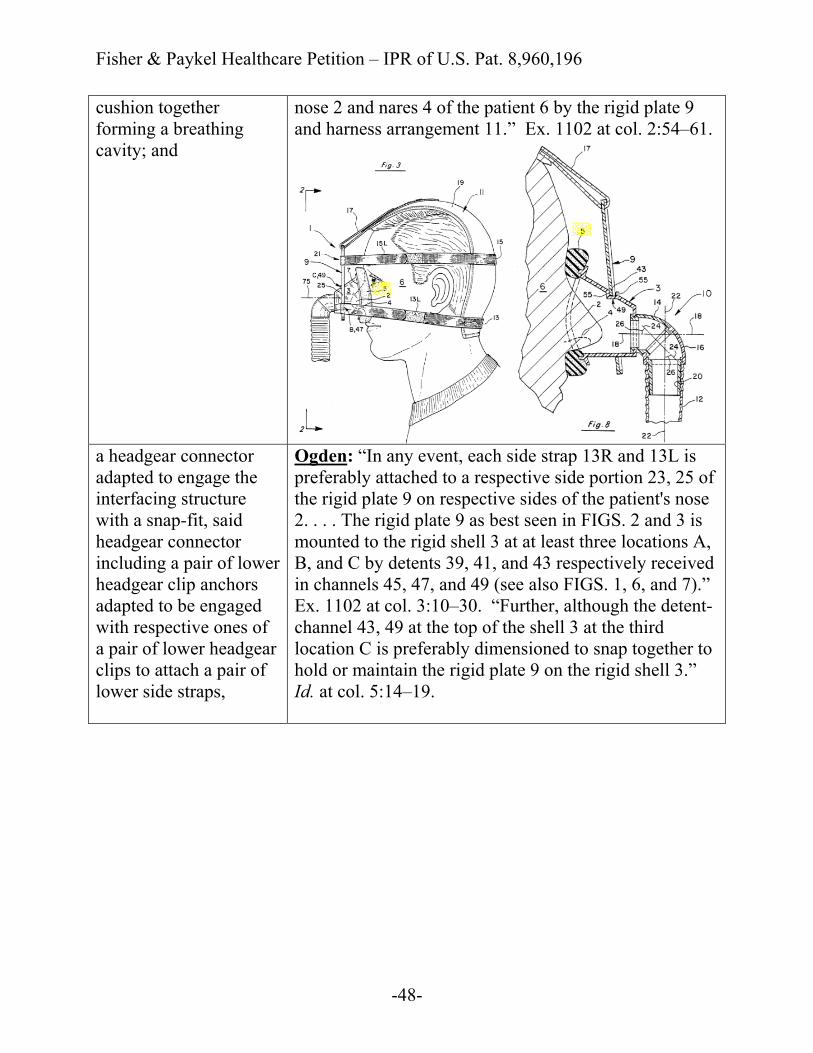
cushion together forming a breathing cavity; and
nose 2 and nares 4 of the patient 6 by the rigid plate 9 and harness arrangement 11.” Ex. 1102 at col. 2:54–61.
a headgear connector adapted to engage the interfacing structure with a snap-fit, said headgear connector including a pair of lower headgear clip anchors adapted to be engaged with respective ones of a pair of lower headgear clips to attach a pair of lower side straps,
Ogden: “In any event, each side strap 13R and 13L is preferably attached to a respective side portion 23, 25 of the rigid plate 9 on respective sides of the patient's nose 2. . . . The rigid plate 9 as best seen in FIGS. 2 and 3 is mounted to the rigid shell 3 at at least three locations A, B, and C by detents 39, 41, and 43 respectively received in channels 45, 47, and 49 (see also FIGS. 1, 6, and 7).” Ex. 1102 at col. 3:10–30. “Further, although the detent-channel 43, 49 at the top of the shell 3 at the third location C is preferably dimensioned to snap together to hold or maintain the rigid plate 9 on the rigid shell 3.” Id. at col. 5:14–19.
Fisher & Paykel Healthcare Petition – IPR of U.S. Pat. 8,960,196
-49-
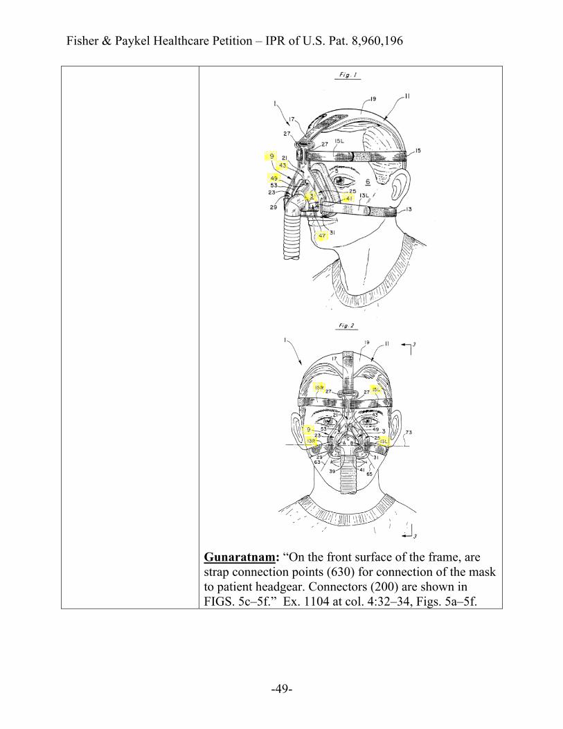
Gunaratnam: “On the front surface of the frame, are strap connection points (630) for connection of the mask to patient headgear. Connectors (200) are shown in FIGS. 5c–5f.” Ex. 1104 at col. 4:32–34, Figs. 5a–5f.

Fisher & Paykel Healthcare Petition – IPR of U.S. Pat. 8,960,196
-50-
said headgear connector including a fixed forehead support, said fixed forehead support including a pair of openings adapted to attach to respective ones of a pair of upper side straps.
Ogden: “The upper side straps in this last regard could be the two straps 15R and 15L as illustrated or one continuous strap passing through loops 27 and anchoring the top portion 21 of the rigid plate 9 (see FIGS. 1–3).” Ex. 1102 at col. 3:7–10.
Gunaratnam: “As compared to FIGS. 5a-5b, FIGS. 5c-5f also show an adjustable forehead support (162) connected to the frame (160).” Ex. 1104 at col. 4:46–48.
Fisher & Paykel Healthcare Petition – IPR of U.S. Pat. 8,960,196
-51-
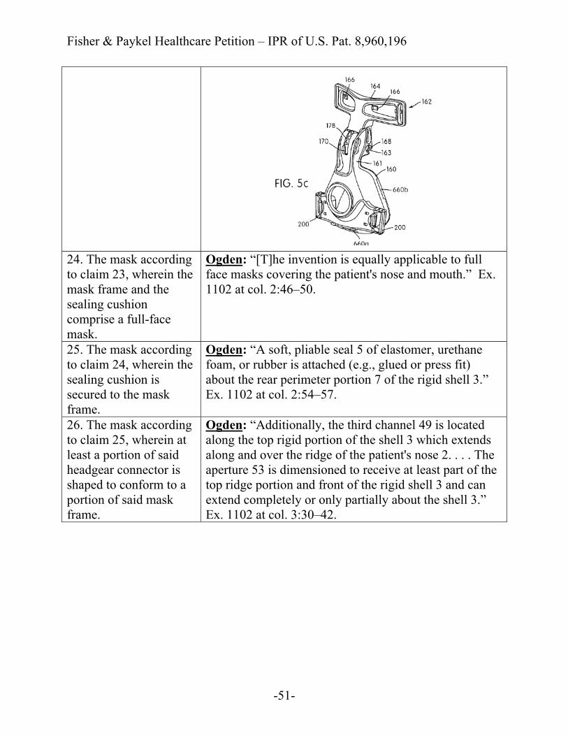
24. The mask according to claim 23, wherein the mask frame and the sealing cushion comprise a full-face mask.
Ogden: “[T]he invention is equally applicable to full face masks covering the patient's nose and mouth.” Ex. 1102 at col. 2:46–50.
25. The mask according to claim 24, wherein the sealing cushion is secured to the mask frame.
Ogden: “A soft, pliable seal 5 of elastomer, urethane foam, or rubber is attached (e.g., glued or press fit) about the rear perimeter portion 7 of the rigid shell 3.” Ex. 1102 at col. 2:54–57.
26. The mask according to claim 25, wherein at least a portion of said headgear connector is shaped to conform to a portion of said mask frame.
Ogden: “Additionally, the third channel 49 is located along the top rigid portion of the shell 3 which extends along and over the ridge of the patient's nose 2. . . . The aperture 53 is dimensioned to receive at least part of the top ridge portion and front of the rigid shell 3 and can extend completely or only partially about the shell 3.” Ex. 1102 at col. 3:30–42.
Fisher & Paykel Healthcare Petition – IPR of U.S. Pat. 8,960,196
-52-
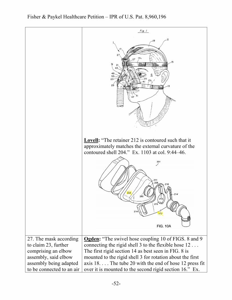
Lovell: “The retainer 212 is contoured such that it approximately matches the external curvature of the contoured shell 204.” Ex. 1103 at col. 9:44–46.
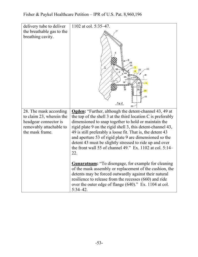
27. The mask according to claim 23, further comprising an elbow assembly, said elbow assembly being adapted to be connected to an air
Ogden: “The swivel hose coupling 10 of FIGS. 8 and 9 connecting the rigid shell 3 to the flexible hose 12 . . . The first rigid section 14 as best seen in FIG. 8 is mounted to the rigid shell 3 for rotation about the first axis 18. . . . The tube 20 with the end of hose 12 press fit over it is mounted to the second rigid section 16.” Ex.
Fisher & Paykel Healthcare Petition – IPR of U.S. Pat. 8,960,196
-53-
delivery tube to deliver the breathable gas to the breathing cavity.
1102 at col. 5:35–47.
28. The mask according to claim 23, wherein the headgear connector is removably attachable to the mask frame.
Ogden: “Further, although the detent-channel 43, 49 at the top of the shell 3 at the third location C is preferably dimensioned to snap together to hold or maintain the rigid plate 9 on the rigid shell 3, this detent-channel 43, 49 is still preferably a loose fit. That is, the detent 43 and aperture 53 of rigid plate 9 are dimensioned so the detent 43 must be slightly stressed to ride up and over the front wall 55 of channel 49.” Ex. 1102 at col. 5:14–22. Gunaratnam: “To disengage, for example for cleaning of the mask assembly or replacement of the cushion, the detents may be forced outwardly against their natural resilience to release from the recesses (660) and ride over the outer edge of flange (640).” Ex. 1104 at col. 5:34–42.

Fisher & Paykel Healthcare Petition – IPR of U.S. Pat. 8,960,196
-54-
29. The mask according to claim 28, wherein when said mask frame and said headgear connector are attached, the mask frame and the headgear connector are not movable relative to one another.
Ogden: “[P]revious mask assemblies of similar construction to the present invention fixedly mounted the rigid plate 9′ to their shell 3′.” Ex. 1102 at col. 3:57–59. Lovell: “The retainer aperture and the inlet 208 are generally sized in an interference fit so that the retainer 212 is properly retained by the cooperation of the tabs 211, 211′, the slots 213, 215, and the depressed annular region 280 when fully seated against the shell 204.” Ex. 1103 at col. 9:59–64.
30. The mask according to claim 23, wherein the bore is located on a
Ogden: “In the illustrated embodiment of a nasal mask, the facial mask assembly 1 of the present invention includes a rigid, cup-shaped shell 3 made of hard plastic
Fisher & Paykel Healthcare Petition – IPR of U.S. Pat. 8,960,196
-55-
front face of the mask frame.
and dimensioned to surround and enclose the patient's nose 2 and nares 4.” Ex. 1102 at col. 2:50–54.
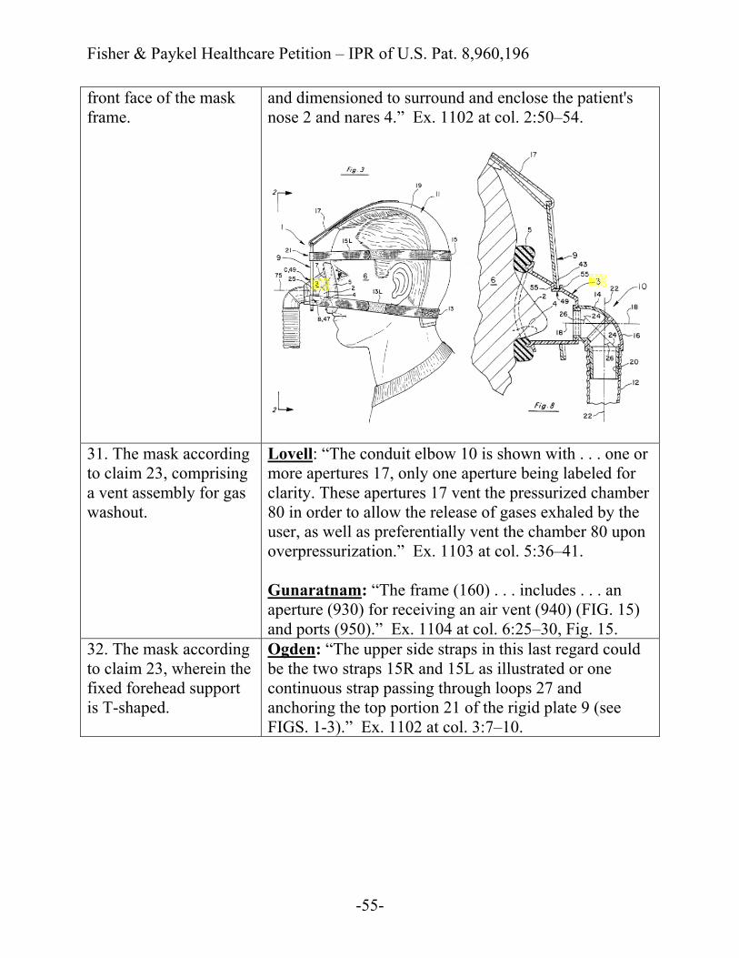
31. The mask according to claim 23, comprising a vent assembly for gas washout.
Lovell: “The conduit elbow 10 is shown with . . . one or more apertures 17, only one aperture being labeled for clarity. These apertures 17 vent the pressurized chamber 80 in order to allow the release of gases exhaled by the user, as well as preferentially vent the chamber 80 upon overpressurization.” Ex. 1103 at col. 5:36–41. Gunaratnam: “The frame (160) . . . includes . . . an aperture (930) for receiving an air vent (940) (FIG. 15) and ports (950).” Ex. 1104 at col. 6:25–30, Fig. 15.
32. The mask according to claim 23, wherein the fixed forehead support is T-shaped.
Ogden: “The upper side straps in this last regard could be the two straps 15R and 15L as illustrated or one continuous strap passing through loops 27 and anchoring the top portion 21 of the rigid plate 9 (see FIGS. 1-3).” Ex. 1102 at col. 3:7–10.
Fisher & Paykel Healthcare Petition – IPR of U.S. Pat. 8,960,196
-56-
Gunaratnam: “As compared to FIGS. 5a-5b, FIGS. 5c-5f also show an adjustable forehead support (162) connected to the frame (160).” Ex. 1104 at col. 4:46–48.
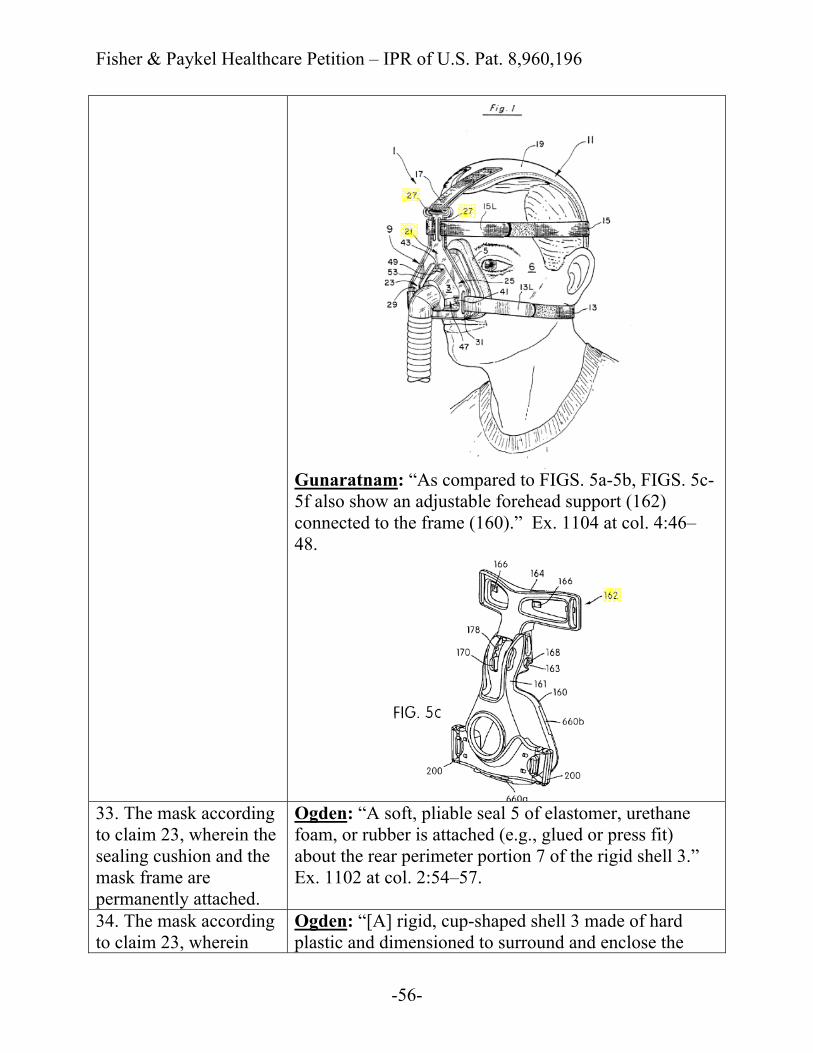
33. The mask according to claim 23, wherein the sealing cushion and the mask frame are permanently attached.
Ogden: “A soft, pliable seal 5 of elastomer, urethane foam, or rubber is attached (e.g., glued or press fit) about the rear perimeter portion 7 of the rigid shell 3.” Ex. 1102 at col. 2:54–57.
34. The mask according to claim 23, wherein
Ogden: “[A] rigid, cup-shaped shell 3 made of hard plastic and dimensioned to surround and enclose the
Fisher & Paykel Healthcare Petition – IPR of U.S. Pat. 8,960,196
-57-
said headgear connector is constructed of a similar material as the mask frame.
patient's nose 2 and nares 4.” Ex. 1102 at col. 2:50–54. “The rigid plate 9 as illustrated in FIGS. 1-3 is preferably flat or planar and made of relatively hard plastic.” Id. at col. 3:25–26.
35. The mask according to claim 23, wherein said headgear connector and said mask frame are constructed of a substantially rigid, non-malleable plastic material.
Ogden: “[A] rigid, cup-shaped shell 3 made of hard plastic and dimensioned to surround and enclose the patient's nose 2 and nares 4.” Ex. 1102 at col. 2:50–54. “The rigid plate 9 as illustrated in FIGS. 1-3 is preferably flat or planar and made of relatively hard plastic.” Id. at col. 3:25–26.
36. The mask according to claim 35, wherein said headgear connector and said mask frame are constructed of polycarbonate.
Gunaratnam: “The frame (160) is constructed as a substantially rigid shell of polycarbonate or similar transparent plastics material, and incorporates a gas inlet aperture (610).” Ex. 1104 at col. 4:22–26. “The clip is conducted from polycarbonate or similar material.” Id. at col. 5:34–35.
37. The mask according to claim 23, further comprising: an elbow assembly, said elbow assembly being adapted to be connected to an air delivery tube to deliver the breathable gas to the breathing cavity; and
See supra Claim 27.
a vent assembly for gas washout,
See supra Claim 31.
wherein the mask frame and the sealing cushion comprise a full-face mask,
See supra Claim 24.
wherein at least a portion of said headgear connector is shaped to conform to a portion of said mask frame,
See supra Claim 26.
wherein the headgear See supra Claim 28.

Fisher & Paykel Healthcare Petition – IPR of U.S. Pat. 8,960,196
-58-
connector is removably attachable to the mask frame, wherein when said mask frame and said headgear connector are attached, the mask frame and the headgear connector are not movable relative to one another,
See supra Claim 29.
wherein the sealing cushion and the mask frame are permanently attached, and
See supra Claim 33.
wherein said headgear connector and said mask frame are constructed of a substantially rigid, non-malleable plastic material.
See supra Claim 35.
38. A mask system for delivering breathable gas to a patient at positive pressure to treat sleep disordered breathing, the mask system comprising:
Ogden: “Facial mask assemblies are widely used in respiratory care and therapy.” Ex. 1102 at col. 1:9–10, Fig. 1. “The flexible hose 12 (which can be connected to a respiratory device such as a ventilator or continuous positive airway pressure (CPAP) device) is then slid over the rigid tube 20.” Id. at col. 5:41–44.
a headgear including the pair of upper side straps, the pair of lower side straps, and a rear portion;
Ogden: “The preferred harness arrangement 11 as illustrated is a five-point attachment one with lower side straps 13R and 13L which extend under the ears and about the back of the patient's head, upper side straps 15R and 15L, and top strap 17. The side straps 13R and 13L (R for right and L for left) can each be separate straps attached to the skull cap 19.” Ex. 1102 at col. 2:62–3:2.
Fisher & Paykel Healthcare Petition – IPR of U.S. Pat. 8,960,196
-59-
and the mask according to claim 23,
See supra Claim 23.
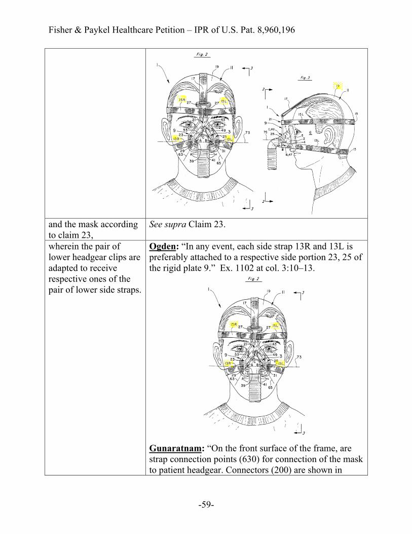
wherein the pair of lower headgear clips are adapted to receive respective ones of the pair of lower side straps.
Ogden: “In any event, each side strap 13R and 13L is preferably attached to a respective side portion 23, 25 of the rigid plate 9.” Ex. 1102 at col. 3:10–13.
Gunaratnam: “On the front surface of the frame, are strap connection points (630) for connection of the mask to patient headgear. Connectors (200) are shown in

Fisher & Paykel Healthcare Petition – IPR of U.S. Pat. 8,960,196
-60-
FIGS. 5c-5f.” Ex. 1104 at col. 4:32–34, Figs. 5a–5f.
39. The mask system according to claim 38, wherein the pair of upper side straps are arranged to extend above the patient's ears and the pair of lower side straps are arranged to extend below the patient's ears.
Ogden: “[A] five-point attachment one with lower side straps 13R and 13L which extend under the ears and about the back of the patient's head, upper side straps 15R and 15L, and top strap 17.” Ex. 1102 at col. 2:62–66.
40. The mask system according to claim 39, wherein the rear portion of the headgear is adapted to cup the occiput of the patient's
Ogden: “The side straps 13R and 13L (R for right and L for left) can each be separate straps attached to the skull cap 19 like the top strap 17 or can be ends of a single strip 13..” Ex. 1102 at col. 2:66–3:1, 3:64–67.
Fisher & Paykel Healthcare Petition – IPR of U.S. Pat. 8,960,196
-61-
head.
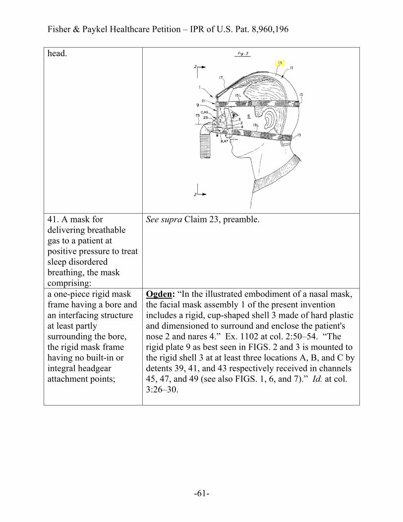
41. A mask for delivering breathable gas to a patient at positive pressure to treat sleep disordered breathing, the mask comprising:
See supra Claim 23, preamble.
a one-piece rigid mask frame having a bore and an interfacing structure at least partly surrounding the bore, the rigid mask frame having no built-in or integral headgear attachment points;
Ogden: “In the illustrated embodiment of a nasal mask, the facial mask assembly 1 of the present invention includes a rigid, cup-shaped shell 3 made of hard plastic and dimensioned to surround and enclose the patient's nose 2 and nares 4.” Ex. 1102 at col. 2:50–54. “The rigid plate 9 as best seen in FIGS. 2 and 3 is mounted to the rigid shell 3 at at least three locations A, B, and C by detents 39, 41, and 43 respectively received in channels 45, 47, and 49 (see also FIGS. 1, 6, and 7).” Id. at col. 3:26–30.
Fisher & Paykel Healthcare Petition – IPR of U.S. Pat. 8,960,196
-62-
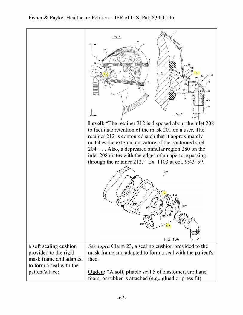
Lovell: “The retainer 212 is disposed about the inlet 208 to facilitate retention of the mask 201 on a user. The retainer 212 is contoured such that it approximately matches the external curvature of the contoured shell 204. . . . Also, a depressed annular region 280 on the inlet 208 mates with the edges of an aperture passing through the retainer 212.” Ex. 1103 at col. 9:43–59.
a soft sealing cushion provided to the rigid mask frame and adapted to form a seal with the patient's face;
See supra Claim 23, a sealing cushion provided to the mask frame and adapted to form a seal with the patient's face. Ogden: “A soft, pliable seal 5 of elastomer, urethane foam, or rubber is attached (e.g., glued or press fit)

Fisher & Paykel Healthcare Petition – IPR of U.S. Pat. 8,960,196
-63-
about the rear perimeter portion 7 of the rigid shell 3 to engage and seal against the patient's face.” Ex. 1102 at col. 2:54–57.
an elbow assembly, said elbow assembly being adapted to be connected to an air delivery tube to deliver the breathable gas to a breathing cavity defined by the rigid mask frame and the soft sealing cushion; and
See supra Claim 23, the mask frame and the sealing cushion together forming a breathing cavity. See supra Claim 27.
a headgear connector having an opening and an attachment structure associated with the opening, the attachment structure being adapted to engage the interfacing structure of the rigid mask frame to removably connect the headgear connector to the rigid mask frame, said bore and said opening being concentrically disposed about a common axis,
Ogden: “each side strap 13R and 13L is preferably attached to a respective side portion 23, 25 of the rigid plate 9 on respective sides of the patient's nose 2. . . . The rigid plate 9 as best seen in FIGS. 2 and 3 is mounted to the rigid shell 3 at at least three locations A, B, and C by detents 39, 41, and 43 respectively received in channels 45, 47, and 49 (see also FIGS. 1, 6, and 7). . . . The aperture 53 is dimensioned to receive at least part of the top ridge portion and front of the rigid shell 3 and can extend completely or only partially about the shell 3.” Ex. 1102 at col. 3:10–42.
Fisher & Paykel Healthcare Petition – IPR of U.S. Pat. 8,960,196
-64-
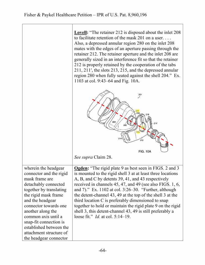
Lovell: “The retainer 212 is disposed about the inlet 208 to facilitate retention of the mask 201 on a user. . . . Also, a depressed annular region 280 on the inlet 208 mates with the edges of an aperture passing through the retainer 212. The retainer aperture and the inlet 208 are generally sized in an interference fit so that the retainer 212 is properly retained by the cooperation of the tabs 211, 211′, the slots 213, 215, and the depressed annular region 280 when fully seated against the shell 204.” Ex. 1103 at col. 9:43–64 and Fig. 10A.
See supra Claim 28.
wherein the headgear connector and the rigid mask frame are detachably connected together by translating the rigid mask frame and the headgear connector towards one another along the common axis until a snap-fit connection is established between the attachment structure of the headgear connector
Ogden: “The rigid plate 9 as best seen in FIGS. 2 and 3 is mounted to the rigid shell 3 at at least three locations A, B, and C by detents 39, 41, and 43 respectively received in channels 45, 47, and 49 (see also FIGS. 1, 6, and 7).” Ex. 1102 at col. 3:26–30. “Further, although the detent-channel 43, 49 at the top of the shell 3 at the third location C is preferably dimensioned to snap together to hold or maintain the rigid plate 9 on the rigid shell 3, this detent-channel 43, 49 is still preferably a loose fit.” Id. at col. 5:14–19.

Fisher & Paykel Healthcare Petition – IPR of U.S. Pat. 8,960,196
-65-
and the interfacing structure of the rigid mask frame, and
Lovell: “Also, a depressed annular region 280 on the inlet 208 mates with the edges of an aperture passing through the retainer 212. The retainer aperture and the inlet 208 are generally sized in an interference fit so that the retainer 212 is properly retained by the cooperation of the tabs 211, 211′, the slots 213, 215, and the depressed annular region 280 when fully seated against the shell 204.” Ex. 1103 at col. 9:57–64 and Fig. 10A.
See supra Claim 28.
Fisher & Paykel Healthcare Petition – IPR of U.S. Pat. 8,960,196
-66-
wherein said headgear connector includes a fixed forehead support.
See supra Claim 23, said headgear connector including a fixed forehead support.
42. The mask according to claim 41, wherein the rigid mask frame and the soft sealing cushion comprise a full-face mask.
See supra Claim 24.
43. The mask according to claim 41, wherein the soft sealing cushion is secured to the rigid mask frame.
See supra Claim 25.
44. The mask according to claim 41, wherein at least a portion of said headgear connector is shaped to conform to a portion of said rigid mask frame.
See supra Claim 26.
45. The mask according to claim 41, wherein when said rigid mask frame and said headgear connector are attached, the rigid mask frame and the headgear connector are not movable relative to one another.
See supra Claim 29.
46. The mask according to claim 41, wherein the bore is located on a front face of the rigid mask frame.
See supra Claim 30.
47. The mask according See supra Claim 31.
Fisher & Paykel Healthcare Petition – IPR of U.S. Pat. 8,960,196
-67-
to claim 41, comprising a vent assembly for gas washout. 48. The mask according to claim 41, wherein the fixed forehead support is T-shaped.
See supra Claim 32.
49. The mask according to claim 41, wherein the soft sealing cushion and the rigid mask frame are permanently attached.
See supra Claim 33.
50. The mask according to claim 41, wherein said headgear connector is constructed of a similar material as the rigid mask frame.
See supra Claim 34.
51. The mask according to claim 41, wherein said headgear connector and said rigid mask frame are constructed of a substantially rigid, non-malleable plastic material.
See supra Claim 35.
52. The mask according to claim 51, wherein said headgear connector and said rigid mask frame are constructed of polycarbonate.
See supra Claim 36.
53. The mask according to claim 41, further comprising a vent assembly for gas washout,
See supra Claim 31.
wherein the rigid mask frame and the soft
See supra Claim 24.
Fisher & Paykel Healthcare Petition – IPR of U.S. Pat. 8,960,196
-68-
sealing cushion comprise a full-face mask, wherein at least a portion of said headgear connector is shaped to conform to a portion of said rigid mask frame,
See supra Claim 26.
wherein when said rigid mask frame and said headgear connector are attached, the rigid mask frame and the headgear connector are not movable relative to one another,
See supra Claim 29.
wherein the soft sealing cushion and the rigid mask frame are permanently attached, and
See supra Claim 33.
wherein said headgear connector and said rigid mask frame are constructed of a substantially rigid, non-malleable plastic material.
See supra Claim 35.
54. A mask system for delivering breathable gas to a patient at positive pressure to treat sleep disordered breathing, the mask system comprising:
See supra Claim 38, preamble.
a headgear including a pair of upper side straps, a pair of lower side straps, and a rear portion;
See supra Claim 38, a headgear including the pair of upper side straps, the pair of lower side straps, and a rear portion.

Fisher & Paykel Healthcare Petition – IPR of U.S. Pat. 8,960,196
-69-
a pair of lower headgear clip anchors formed on said headgear connector and adapted to be engaged with respective ones of a pair of lower headgear clips to attach the pair of lower side straps, the pair of lower headgear clips being adapted to receive respective ones of the pair of lower side straps;
See supra Claim 23, said headgear connector including a pair of lower headgear clip anchors adapted to be engaged with respective ones of a pair of lower headgear clips to attach a pair of lower side straps. See also supra Claim 38, wherein the pair of lower headgear clips are adapted to receive respective ones of the pair of lower side straps.
a pair of openings formed on said forehead support adapted to attach to respective ones of the pair of upper side straps; and
See supra Claim 23, said fixed forehead support including a pair of openings adapted to attach to respective ones of a pair of upper side straps.
the mask according to claim 41.
See supra Claim 41.
55. The mask system according to claim 54, wherein the pair of upper side straps are arranged to extend above the patient's ears and the pair of lower side straps are arranged to extend below the patient's ears.
See supra Claim 39.
56. The mask system according to claim 55, wherein the rear portion of the headgear is adapted to cup the occiput of the patient's head.
See supra Claim 40.
57. A mask system for delivering breathable
See supra Claim 23, preamble.
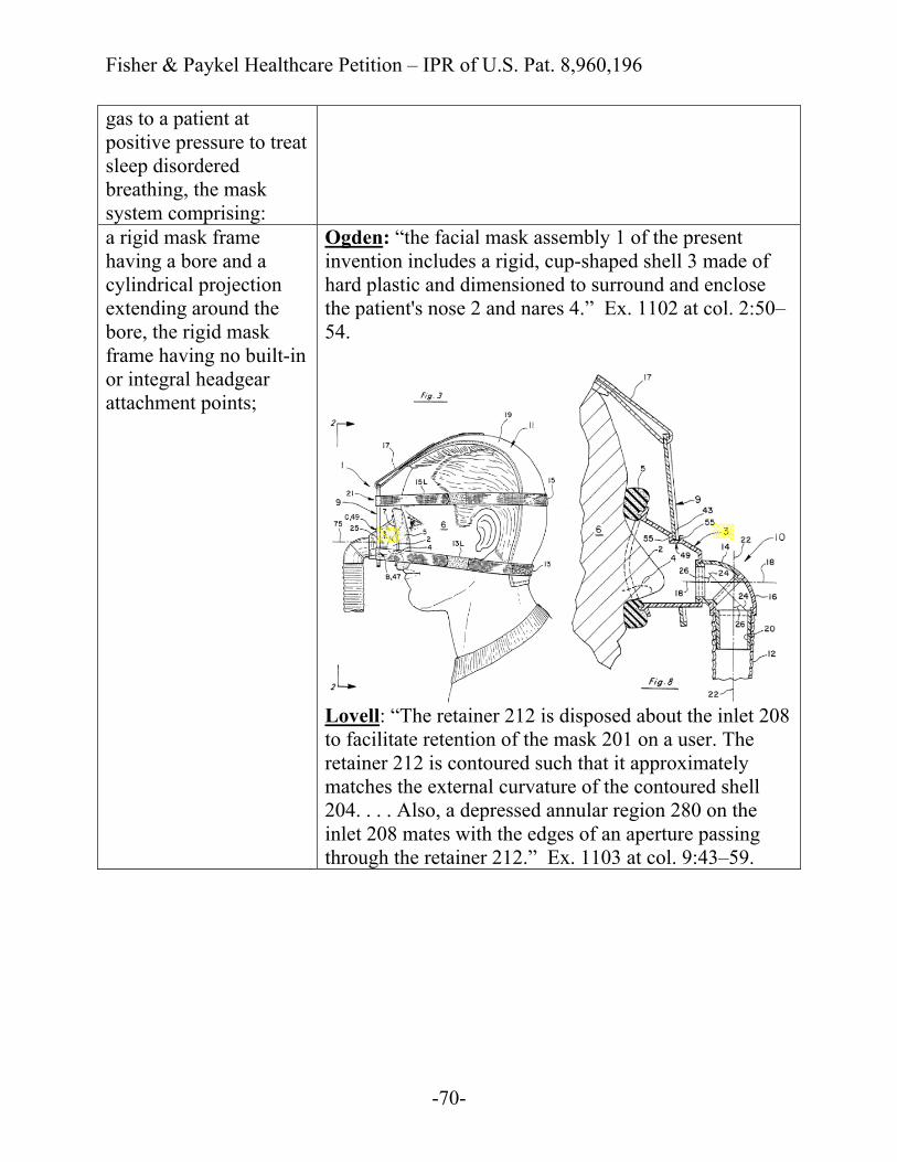
Fisher & Paykel Healthcare Petition – IPR of U.S. Pat. 8,960,196
-70-
gas to a patient at positive pressure to treat sleep disordered breathing, the mask system comprising: a rigid mask frame having a bore and a cylindrical projection extending around the bore, the rigid mask frame having no built-in or integral headgear attachment points;
Ogden: “the facial mask assembly 1 of the present invention includes a rigid, cup-shaped shell 3 made of hard plastic and dimensioned to surround and enclose the patient's nose 2 and nares 4.” Ex. 1102 at col. 2:50–54.
Lovell: “The retainer 212 is disposed about the inlet 208 to facilitate retention of the mask 201 on a user. The retainer 212 is contoured such that it approximately matches the external curvature of the contoured shell 204. . . . Also, a depressed annular region 280 on the inlet 208 mates with the edges of an aperture passing through the retainer 212.” Ex. 1103 at col. 9:43–59.
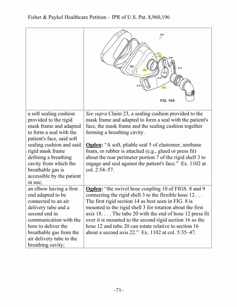
Fisher & Paykel Healthcare Petition – IPR of U.S. Pat. 8,960,196
-71-
a soft sealing cushion provided to the rigid mask frame and adapted to form a seal with the patient's face, said soft sealing cushion and said rigid mask frame defining a breathing cavity from which the breathable gas is accessible by the patient in use;
See supra Claim 23, a sealing cushion provided to the mask frame and adapted to form a seal with the patient's face, the mask frame and the sealing cushion together forming a breathing cavity. Ogden: “A soft, pliable seal 5 of elastomer, urethane foam, or rubber is attached (e.g., glued or press fit) about the rear perimeter portion 7 of the rigid shell 3 to engage and seal against the patient's face.” Ex. 1102 at col. 2:54–57.
an elbow having a first end adapted to be connected to an air delivery tube and a second end in communication with the bore to deliver the breathable gas from the air delivery tube to the breathing cavity;
Ogden: “the swivel hose coupling 10 of FIGS. 8 and 9 connecting the rigid shell 3 to the flexible hose 12 . . . The first rigid section 14 as best seen in FIG. 8 is mounted to the rigid shell 3 for rotation about the first axis 18. . . . The tube 20 with the end of hose 12 press fit over it is mounted to the second rigid section 16 so the hose 12 and tube 20 can rotate relative to section 16 about a second axis 22.” Ex. 1102 at col. 5:35–47.

Fisher & Paykel Healthcare Petition – IPR of U.S. Pat. 8,960,196
-72-
headgear including a pair of upper side straps, a pair of lower side straps, and a rear portion from which the upper side straps and the lower side straps extend; and
See supra Claim 38, a headgear including the pair of upper side straps, the pair of lower side straps, and a rear portion.
a headgear connector having an opening with an attachment structure associated with the opening,
See supra Claim 41, a headgear connector having an opening and an attachment structure associated with the opening.
the attachment structure removably attached to the cylindrical projection of the rigid mask frame with a snap-fit such that when said cylindrical projection and said attachment structure are attached, the rigid mask frame and the headgear
Ogden: “The rigid plate 9 as best seen in FIGS. 2 and 3 is mounted to the rigid shell 3 at at least three locations A, B, and C by detents 39, 41, and 43 respectively received in channels 45, 47, and 49 (see also FIGS. 1, 6, and 7).” Ex. 1102 at col. 3:26–30. “Further, although the detent-channel 43, 49 at the top of the shell 3 at the third location C is preferably dimensioned to snap together to hold or maintain the rigid plate 9 on the rigid shell 3, this detent-channel 43, 49 is still preferably a loose fit.” Id. at col. 5:14–19.

Fisher & Paykel Healthcare Petition – IPR of U.S. Pat. 8,960,196
-73-
connector are not movable relative to one another, wherein said opening and said bore are concentrically disposed about a common axis,
Lovell: “The retainer 212 is disposed about the inlet 208 to facilitate retention of the mask 201 on a user. . . . Also, a depressed annular region 280 on the inlet 208 mates with the edges of an aperture passing through the retainer 212. The retainer aperture and the inlet 208 are generally sized in an interference fit so that the retainer 212 is properly retained by the cooperation of the tabs 211, 211′, the slots 213, 215, and the depressed annular region 280 when fully seated against the shell 204.” Ex. 1103 at col. 9:43–64.
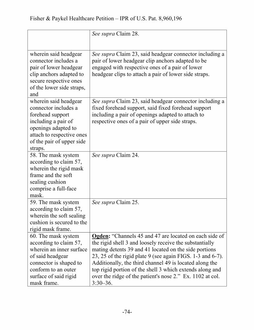
Fisher & Paykel Healthcare Petition – IPR of U.S. Pat. 8,960,196
-74-
See supra Claim 28.
wherein said headgear connector includes a pair of lower headgear clip anchors adapted to secure respective ones of the lower side straps, and
See supra Claim 23, said headgear connector including a pair of lower headgear clip anchors adapted to be engaged with respective ones of a pair of lower headgear clips to attach a pair of lower side straps.
wherein said headgear connector includes a forehead support including a pair of openings adapted to attach to respective ones of the pair of upper side straps.
See supra Claim 23, said headgear connector including a fixed forehead support, said fixed forehead support including a pair of openings adapted to attach to respective ones of a pair of upper side straps.
58. The mask system according to claim 57, wherein the rigid mask frame and the soft sealing cushion comprise a full-face mask.
See supra Claim 24.
59. The mask system according to claim 57, wherein the soft sealing cushion is secured to the rigid mask frame.
See supra Claim 25.
60. The mask system according to claim 57, wherein an inner surface of said headgear connector is shaped to conform to an outer surface of said rigid mask frame.
Ogden: “Channels 45 and 47 are located on each side of the rigid shell 3 and loosely receive the substantially mating detents 39 and 41 located on the side portions 23, 25 of the rigid plate 9 (see again FIGS. 1-3 and 6-7). Additionally, the third channel 49 is located along the top rigid portion of the shell 3 which extends along and over the ridge of the patient's nose 2.” Ex. 1102 at col. 3:30–36.
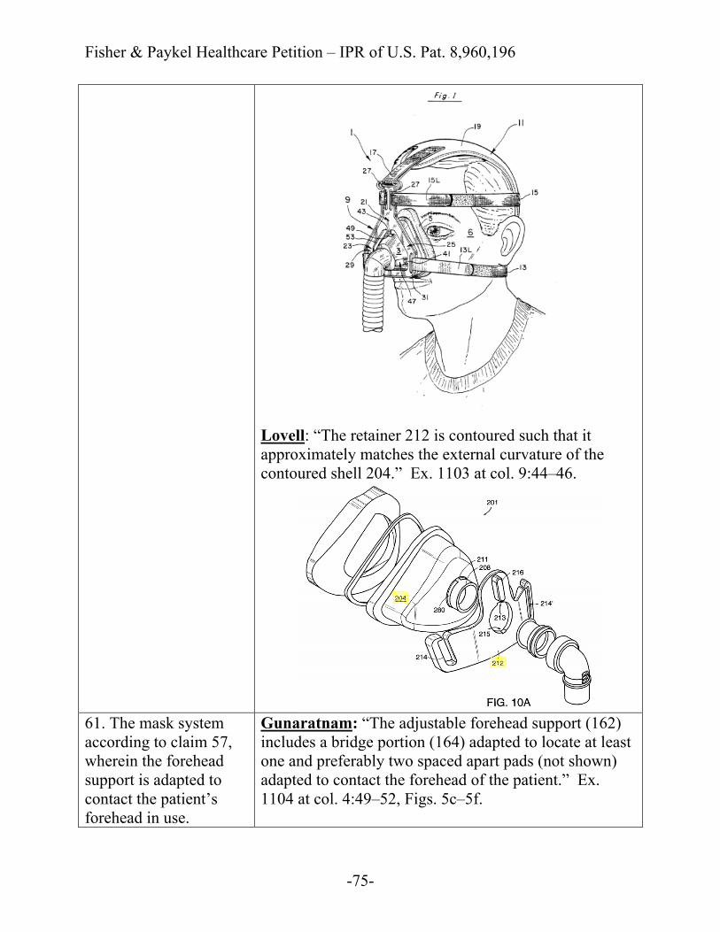
Fisher & Paykel Healthcare Petition – IPR of U.S. Pat. 8,960,196
-75-
Lovell: “The retainer 212 is contoured such that it approximately matches the external curvature of the contoured shell 204.” Ex. 1103 at col. 9:44–46.
61. The mask system according to claim 57, wherein the forehead support is adapted to contact the patient’s forehead in use.
Gunaratnam: “The adjustable forehead support (162) includes a bridge portion (164) adapted to locate at least one and preferably two spaced apart pads (not shown) adapted to contact the forehead of the patient.” Ex. 1104 at col. 4:49–52, Figs. 5c–5f.
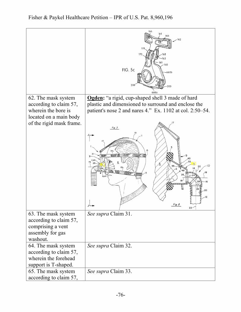
Fisher & Paykel Healthcare Petition – IPR of U.S. Pat. 8,960,196
-76-
62. The mask system according to claim 57, wherein the bore is located on a main body of the rigid mask frame.
Ogden: “a rigid, cup-shaped shell 3 made of hard plastic and dimensioned to surround and enclose the patient's nose 2 and nares 4.” Ex. 1102 at col. 2:50–54.
63. The mask system according to claim 57, comprising a vent assembly for gas washout.
See supra Claim 31.
64. The mask system according to claim 57, wherein the forehead support is T-shaped.
See supra Claim 32.
65. The mask system according to claim 57,
See supra Claim 33.
Fisher & Paykel Healthcare Petition – IPR of U.S. Pat. 8,960,196
-77-
wherein the soft sealing cushion and the rigid mask frame are permanently attached. 66. The mask system according to claim 57, wherein said headgear connector is constructed of a similar material as the rigid frame.
See supra Claim 34.
67. The mask system according to claim 57, wherein said headgear connector and said mask frame are constructed of a substantially rigid, non-malleable plastic material.
See supra Claim 35.
68. The mask system according to claim 67, wherein said headgear connector and said rigid mask frame are constructed of polycarbonate.
See supra Claim 36.
69. The mask system according to claim 57, wherein the attachment structure and the cylindrical projection are engaged with the snap-fit when the attachment structure and the cylindrical projection are engaged in a nested arrangement.
Ogden: “The rigid plate 9 as best seen in FIGS. 2 and 3 is mounted to the rigid shell 3 at at least three locations A, B, and C by detents 39, 41, and 43 respectively received in channels 45, 47, and 49 (see also FIGS. 1, 6, and 7). . . . The aperture 53 is dimensioned to receive at least part of the top ridge portion and front of the rigid shell 3 and can extend completely or only partially about the shell 3.” Ex. 1102 at col. 3:26–42.
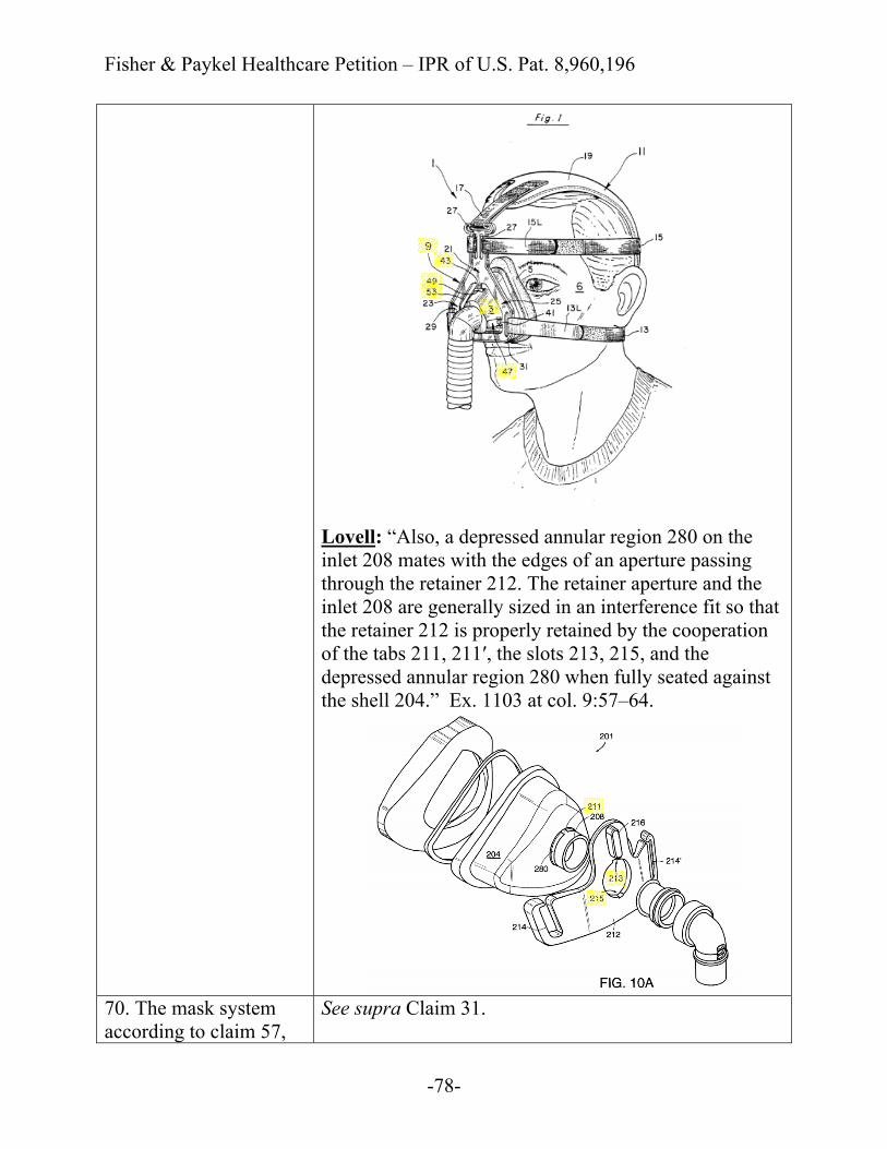
Fisher & Paykel Healthcare Petition – IPR of U.S. Pat. 8,960,196
-78-
Lovell: “Also, a depressed annular region 280 on the inlet 208 mates with the edges of an aperture passing through the retainer 212. The retainer aperture and the inlet 208 are generally sized in an interference fit so that the retainer 212 is properly retained by the cooperation of the tabs 211, 211′, the slots 213, 215, and the depressed annular region 280 when fully seated against the shell 204.” Ex. 1103 at col. 9:57–64.
70. The mask system according to claim 57,
See supra Claim 31.

Fisher & Paykel Healthcare Petition – IPR of U.S. Pat. 8,960,196
-79-
further comprising a vent assembly for gas washout, wherein the rigid mask frame and the soft sealing cushion comprise a full-face mask,
See supra Claim 24.
wherein an inner surface of said headgear connector is shaped to conform to an outer surface of said mask frame,
See supra Claim 60.
wherein the forehead support is adapted to contact the patient’s forehead in use,
See supra Claim 61.
wherein the soft sealing cushion and the rigid mask frame are permanently attached, and
See supra Claim 33.
wherein said headgear connector and said rigid mask frame are constructed of a substantially rigid, non-malleable plastic material.
See supra Claim 35.
71. The mask system according to claim 57, wherein the pair of upper side straps are arranged to extend above the patient's ears and the pair of lower side straps are arranged to extend below the patient's ears.
See supra Claim 39.
Fisher & Paykel Healthcare Petition – IPR of U.S. Pat. 8,960,196
-80-
72. The mask system according to claim 71, wherein the rear portion of the headgear is adapted to cup the occiput of the patient's head.
See supra Claim 40.
73. A mask for delivering breathable gas to a patient at positive pressure to treat sleep disordered breathing, the mask comprising:
See supra Claim 23, preamble.
a rigid mask frame having a bore and no built-in or integral headgear attachment points;
See supra Claim 23, a rigid mask frame having a bore and an interfacing structure associated with the bore, said mask frame having no built-in or integral headgear attachment points.
a soft sealing cushion attached to the rigid mask frame and adapted to form a seal with the patient's face, the rigid mask frame and the soft sealing cushion together forming a breathing cavity to receive the breathable gas; and
See supra Claim 23, a sealing cushion provided to the mask frame and adapted to form a seal with the patient's face, the mask frame and the sealing cushion together forming a breathing cavity. Ogden: “A soft, pliable seal 5 of elastomer, urethane foam, or rubber is attached . . . about the rear perimeter portion 7 of the rigid shell 3.” Ex. 1102 at col. 2:54–57.
a headgear connector including a plurality of tabs structured to removably attach the headgear connector to the rigid mask frame with a snap-fit,
Ogden: “The rigid plate 9 as best seen in FIGS. 2 and 3 is mounted to the rigid shell 3 at at least three locations A, B, and C by detents 39, 41, and 43 respectively received in channels 45, 47, and 49 (see also FIGS. 1, 6, and 7).” Ex. 1102 at col. 3:26–30. “Further, although the detent-channel 43, 49 at the top of the shell 3 at the third location C is preferably dimensioned to snap together to hold or maintain the rigid plate 9 on the rigid shell 3, this detent-channel 43, 49 is still preferably a loose fit.” Id. at col. 5:14–19.

Fisher & Paykel Healthcare Petition – IPR of U.S. Pat. 8,960,196
-81-
Lovell: “The retainer aperture and the inlet 208 are generally sized in an interference fit so that the retainer 212 is properly retained by the cooperation of the tabs 211, 211′, the slots 213, 215, and the depressed annular region 280 when fully seated against the shell 204.” Ex. 1103 at col. 9:59–64.

Fisher & Paykel Healthcare Petition – IPR of U.S. Pat. 8,960,196
-82-
See supra Claim 28.
a pair of crossbars to removably attach a pair of lower side straps, and
Ogden: “In any event, each side strap 13R and 13L is preferably attached to a respective side portion 23, 25 of the rigid plate 9 on respective sides of the patient's nose 2. This can be done in any number of well-known, adjustable manners including looping the straps 13R and 13L through the openings 29, 31 in the rigid plate 9 and fastening them back on themselves by hook and loop materials on the straps themselves.” Ex. 1102 at col. 3:10–17.
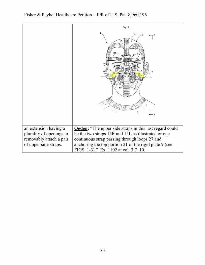
Fisher & Paykel Healthcare Petition – IPR of U.S. Pat. 8,960,196
-83-
an extension having a plurality of openings to removably attach a pair of upper side straps.
Ogden: “The upper side straps in this last regard could be the two straps 15R and 15L as illustrated or one continuous strap passing through loops 27 and anchoring the top portion 21 of the rigid plate 9 (see FIGS. 1-3).” Ex. 1102 at col. 3:7–10.
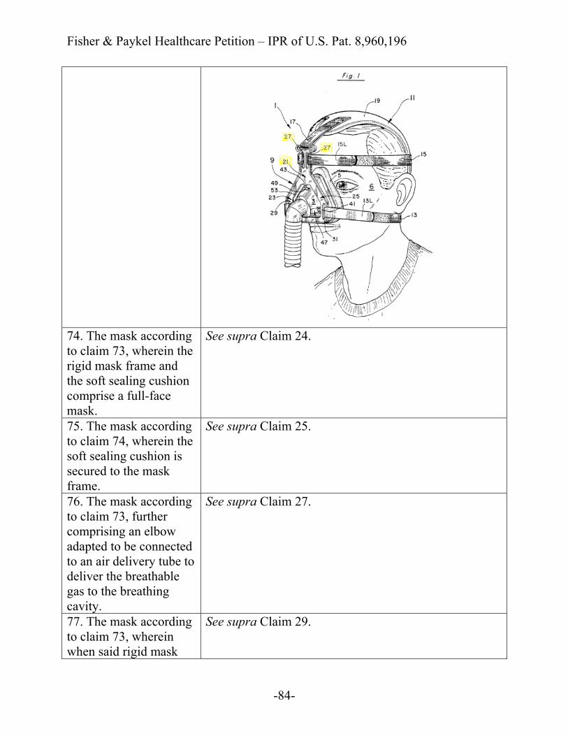
Fisher & Paykel Healthcare Petition – IPR of U.S. Pat. 8,960,196
-84-
74. The mask according to claim 73, wherein the rigid mask frame and the soft sealing cushion comprise a full-face mask.
See supra Claim 24.
75. The mask according to claim 74, wherein the soft sealing cushion is secured to the mask frame.
See supra Claim 25.
76. The mask according to claim 73, further comprising an elbow adapted to be connected to an air delivery tube to deliver the breathable gas to the breathing cavity.
See supra Claim 27.
77. The mask according to claim 73, wherein when said rigid mask
See supra Claim 29.
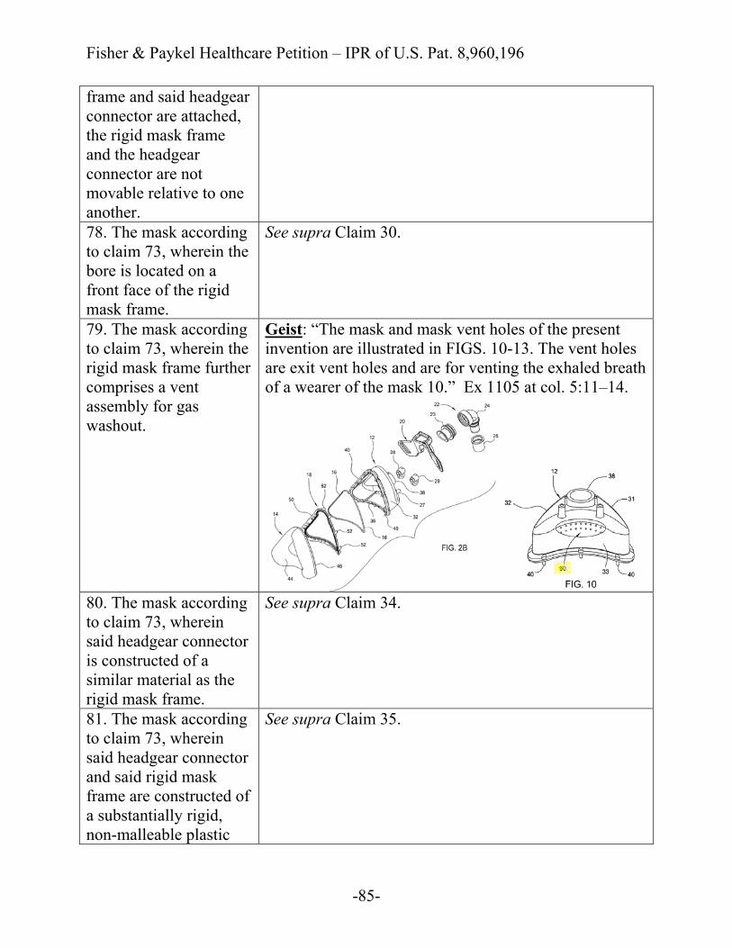
Fisher & Paykel Healthcare Petition – IPR of U.S. Pat. 8,960,196
-85-
frame and said headgear connector are attached, the rigid mask frame and the headgear connector are not movable relative to one another. 78. The mask according to claim 73, wherein the bore is located on a front face of the rigid mask frame.
See supra Claim 30.
79. The mask according to claim 73, wherein the rigid mask frame further comprises a vent assembly for gas washout.
Geist: “The mask and mask vent holes of the present invention are illustrated in FIGS. 10-13. The vent holes are exit vent holes and are for venting the exhaled breath of a wearer of the mask 10.” Ex 1105 at col. 5:11–14.
80. The mask according to claim 73, wherein said headgear connector is constructed of a similar material as the rigid mask frame.
See supra Claim 34.
81. The mask according to claim 73, wherein said headgear connector and said rigid mask frame are constructed of a substantially rigid, non-malleable plastic
See supra Claim 35.
Fisher & Paykel Healthcare Petition – IPR of U.S. Pat. 8,960,196
-86-
material. 82. The mask according to claim 81, wherein said headgear connector and said rigid mask frame are constructed of polycarbonate.
See supra Claim 36.
83. The mask according to claim 73, further comprising: an elbow adapted to be connected to an air delivery tube to deliver the breathable gas to the breathing cavity,
See supra Claim 27.
wherein the rigid mask frame further comprises a vent assembly for gas washout,
See supra Claim 79.
wherein the rigid mask frame and the soft sealing cushion comprise a full-face mask,
See supra Claim 24.
wherein when said rigid mask frame and said headgear connector are attached, the rigid mask frame and the headgear connector are not movable relative to one another, and
See supra Claim 29.
wherein said headgear connector and said rigid mask frame are constructed of a substantially rigid, non-malleable plastic material.
See supra Claim 35.
Fisher & Paykel Healthcare Petition – IPR of U.S. Pat. 8,960,196
-87-
84. A mask system for delivering breathable gas to a patient at positive pressure to treat sleep disordered breathing, the mask system comprising:
See supra Claim 38, preamble.
a headgear including the pair of upper side straps, the pair of lower side straps, and a rear portion; and
See supra Claim 38, a headgear including the pair of upper side straps, the pair of lower side straps, and a rear portion.
a mask according to claim 73.
See supra Claim 73.
85. The mask system according to claim 84, wherein the pair of upper side straps are arranged to extend above the patient's ears and the pair of lower side straps are arranged to extend below the patient's ears.
See supra Claim 39.
86. The mask system according to claim 85, wherein the rear portion of the headgear is adapted to cup the occiput of the patient's head.
See supra Claim 40.
A. Secondary Considerations, Even if Considered, Fail to Overcome the Prima Facie Evidence of Obviousness
To overcome the strong showing of obviousness set forth above, the Patent
Owner may attempt to present alleged secondary considerations of non-
Fisher & Paykel Healthcare Petition – IPR of U.S. Pat. 8,960,196
-88-
obviousness. However, secondary considerations do not support a finding of non-
obviousness here. Although secondary considerations should be taken into
account, they do not control the obviousness conclusion. Newell Cos., Inc. v.
Kenney Mfg. Co., 864 F.2d 757, 768 (Fed. Cir. 1988). And where a strong prima
facie obviousness showing exists, as here, the Federal Circuit has repeatedly held
that even relevant secondary considerations supported by substantial evidence may
not dislodge the primary conclusion of obviousness. See, e.g., Leapfrog Enters.
Inc. v. Fisher-Price, Inc., 485 F.3d 1157, 1162 (Fed. Cir. 2007). For example,
evidence of commercial sales generally would not be sufficient to overcome the
strong showing of obviousness and there would be no nexus between the
commercial sales and the Challenged Claims. See, e.g., Wyers v. Master Lock Co.,
616 F.3d 1231, 1246 (Fed. Cir. 2010).
Petitioner is not aware of any secondary considerations that would be
relevant to the obviousness inquiries presented here. Further, Petitioner does not
believe that any potential secondary considerations could outweigh the strong
prima facie case of obviousness. In the event that the Patent Owner puts forth any
allegations regarding secondary considerations of non-obviousness, Petitioner will
address those allegations in due course.
Fisher & Paykel Healthcare Petition – IPR of U.S. Pat. 8,960,196
-89-
Respectfully submitted,
KNOBBE, MARTENS, OLSON & BEAR, LLP Dated: October 11, 2016 By: /Brenton R. Babcock/
Brenton R. Babcock (Reg. No. 39,592) Benjamin J. Everton (Reg. No. 60,659) Customer No. 20,995
Attorneys for Petitioner Fisher & Paykel Healthcare Limited
(949) 760-0404
Fisher & Paykel Healthcare Petition – IPR of U.S. Pat. 8,960,196
CERTIFICATE OF TYPE-VOLUME LIMITATIONS
UNDER 37 C.F.R. § 42.24
Pursuant to 37 C.F.R. § 42.24(d), Counsel for Petitioner Fisher & Paykel
Healthcare Limited hereby certifies that this document complies with the type-
volume limitation of 37 C.F.R. § 42.24(a)(1)(i). According to Microsoft Office
Word 2010’s word count, this document contains approximately 13,831 words,
including any statement of material facts to be admitted or denied in support, and
excluding the table of contents, table of authorities, mandatory notices under
§ 42.8, exhibit list, certificate of service or word count, or appendix of exhibits or
claim listing.
Respectfully submitted,
KNOBBE, MARTENS, OLSON & BEAR, LLP Dated: October 11, 2016 By: /Brenton R. Babcock/
Brenton R. Babcock (Reg. No. 39,592) Benjamin J. Everton (Reg. No. 60,659) Customer No. 20,995
Attorneys for Petitioner Fisher & Paykel Healthcare Limited
(949) 760-0404
Fisher & Paykel Healthcare Petition – IPR of U.S. Pat. 8,960,196
CERTIFICATE OF SERVICE
I hereby certify that true and correct copies of the foregoing PETITION
FOR INTER PARTES REVIEW OF U.S. PATENT 8,960,196 and Fisher &
Paykel Healthcare Exhibits 1101–1111 are being served on October 11, 2016, via
FedEx Priority Overnight service on counsel of record for U.S. Patent 8,960,196
patent owner RESMED LIMITED at the address below:
Correspondence Address of Record for U.S. Patent 8,960,196 at the U.S.
Patent and Trademark Office:
Nixon & Vanderhye, PC 901 North Glebe Road, 11th Floor
Arlington, VA 22203
Dated: October 11, 2016 By: /Brenton R. Babcock/
Brenton R. Babcock Registration No. 39,592 Attorney for Petitioner Fisher & Paykel Healthcare Limited
23523958