before you continue - nasa · mechanism involved with hydrogen embrittlement, increased greatly,...
TRANSCRIPT

NASA/TM-2016–218602
Hydrogen Embrittlement Jonathan A. Lee National Aeronautics and Space Administration Marshall Space Flight Center Huntsville, Alabama
April 2016
https://ntrs.nasa.gov/search.jsp?R=20160005654 2018-07-08T17:56:14+00:00Z

NASA STI Program ... in Profile
Since its founding, NASA has been dedicated to the advancement of aeronautics and space science. The NASA scientific and technical information (STI) program plays a key part in helping NASA maintain this important role.
The NASA STI program operates under the auspices of the Agency Chief Information Officer. It collects, organizes, provides for archiving, and disseminates NASA’s STI. The NASA STI program provides access to the NTRS Registered and its public interface, the NASA Technical Reports Server, thus providing one of the largest collections of aeronautical and space science STI in the world. Results are published in both non-NASA channels and by NASA in the NASA STI Report Series, which includes the following report types:
• TECHNICAL PUBLICATION. Reports of
completed research or a major significant phase of research that present the results of NASA Programs and include extensive data or theoretical analysis. Includes compila- tions of significant scientific and technical data and information deemed to be of continuing reference value. NASA counter-part of peer-reviewed formal professional papers but has less stringent limitations on manuscript length and extent of graphic presentations.
• TECHNICAL MEMORANDUM. Scientific and technical findings that are preliminary or of specialized interest, e.g., quick release reports, working papers, and bibliographies that contain minimal annotation. Does not contain extensive analysis.
• CONTRACTOR REPORT. Scientific and technical findings by NASA-sponsored contractors and grantees.
• CONFERENCE PUBLICATION. Collected papers from scientific and technical conferences, symposia, seminars, or other meetings sponsored or co-sponsored by NASA.
• SPECIAL PUBLICATION. Scientific, technical, or historical information from NASA programs, projects, and missions, often concerned with subjects having substantial public interest.
• TECHNICAL TRANSLATION. English-language translations of foreign scientific and technical material pertinent to NASA’s mission.
Specialized services also include organizing and publishing research results, distributing specialized research announcements and feeds, providing information desk and personal search support, and enabling data exchange services.
For more information about the NASA STI program, see the following:
• Access the NASA STI program home page
at http://www.sti.nasa.gov
• E-mail your question to [email protected]
• Phone the NASA STI Information Desk at 757-864-9658
• Write to: NASA STI Information Desk Mail Stop 148 NASA Langley Research Center Hampton, VA 23681-2199
This page is required and contains approved text that cannot be changed.

NASA/TM—2016–218602
Hydrogen Embrittlement Jonathan A. Lee NASA Marshall Space Flight Center Huntsville, Alabama
National Aeronautics and Space Administration NASA Marshall Space Flight Center Huntsville, Alabama
April 2016


Acknowledgments The author gratefully acknowledges the work of reviewers Stephen S. Woods and Stephen H. McDougle, and editor Claire G. Meador, from NASA Johnson Space Center White Sands Test Facility.
Available from:
This report is available in electronic form at
http://

i
Contents
Section Page Tables iii Figures iv Definitions v Acronyms vi Foreword vii 1.0 Introduction 1 2.0 Classification of Hydrogen Embrittlement 1
2.1 Hydrogen Environmental Embrittlement 2 2.2 Internal Hydrogen Embrittlement 3 2.3 Hydrogen Reaction Embrittlement 3 2.4 Hydrogen Embrittlement versus Stress Corrosion Cracking 4
3.0 Hydrogen Embrittlement Characterization 5
3.1 Material Screening Methods 5 3.2 Qualitative Ratings 6 3.3 Material Database for Hydrogen Environment Embrittlement 7 3.4 General Observation for Metallic Materials 13
Aluminum and Aluminum Alloys 13 Copper and Copper Alloys 13 Nickel and Nickel based Alloys 13 Titanium and Titanium Alloys 14 Iron-based Alloys and Steels 14 Superalloys 15
4.0 Hydrogen Effects on Mechanical Properties 15
4.1 Tensile Properties 15 4.2 Fracture Properties 15 4.3 Low Cycle Fatigue 19 4.4 High Cycle Fatigue 21 4.5 Crack Growth Rate 22 4.6 Creep Rupture 23
5.0 Important Factors in Hydrogen Embrittlement 25
5.1 Hydrogen Pressure 25 5.2 Temperature 26 5.3 Heat Treatment and Product Forms 28 5.4 Alloy Compositions 31 5.5 Surface Finish 34 5.6 Grain Directions and Crystal Orientations 34

ii
Contents (continued) Section Page 6.0 Prevention and Control Methods for Hydrogen Damage 35
6.1 General Guidelines 35 6.2 Controlling the Material Factors 36
Select Proper Materials 36 Select Steels Using Nelson Curve for Corrosive Environment 37 Select Proper Thermo-mechanical Treatment 38 Surface Barriers and Coatings for Limited and Short-term Applications 38
6.3 Controlling the Hydrogen Factors 38 Reduce Hydrogen Gas Pressure 38 Reduce Hydrogen Gas Purity 39 Select Proper Operating Temperature 39 Hydrogen Relief by Bake Out 40 Reduce Material Cooling Rate in Gaseous Hydrogen Environment 41 Use Proper Welding Procedures 41 Controlling Cathodic Protection System 41 Application of Inhibitors in Liquid Environment 41
6.4 Controlling the Stress Factors 42 Reduce External Applied Stress 42 Reduce Internal Residual Stress 42 Application of Fracture Mechanics 42
7.0 Hydrogen Codes and Standards in the U.S. 43 8.0 References 44

iii
Tables Table Page 1 Material screening for hydrogen embrittlement based on HEE Index
from NTS ratio 7 2 HEE Indexes for selected metals tested at 24 °C under high
hydrogen pressure 8 3 HEE Indexes for selected steels tested at 24 °C under high
hydrogen pressure 9 4 HEE Indexes for selected superalloys tested at 24 °C under high
hydrogen pressure 11 5 Threshold stress intensity (KTH) for A-286, JBK-75 and Incolo 903
in hydrogen 16 6 Hydrogen effects on life reduction factor under LCF loading at various
temperatures 20 7 Effects of heat treatment & product forms on HEE index for superalloys 29 8 Effects of solution treatment and aging time on superalloys 30 9 Effects of heat treatment and product forms for Inconel® 718 superalloy 31 10 HEE Index for Fe-Ni-Cr superalloys and stainless steels as
a function of Ni content (wt.%) 32 11 HEE Effects on grain direction of selected wrought superalloys 34 12 HEE Effects on crystal orientation for PWA 1480E superalloy 35

iv
Figures Figure Page 1 Classification of HEE, IHE and HRE type based hydrogen, stress and
material factors 2
2 Distinction between HE and SCC based on the behavior of strain rates during test 5
3 Trend line for HEE effects on NTS and RA for electro-deposited nickel 6 4 Effects of hydrogen pressure on threshold stress intensity (KTH)
for superalloys 17 5 Trend lines for Inconel 718 based on HEE index from KIH/KIC and RA ratio 18 6 Effects of hydrogen on strain Controlled Low Cycle Fatigue (LCF)
of superalloys 19 7 Effects on HCF of Inconel 718 in 34.5 MPa hydrogen pressure at room
temperature 21 8 HEE effects for cyclic crack growth rates (da/dN) for several superalloys 22 9 Larson-Miller Parameter for creep-rupture of Inconel 718 tested in hydrogen 23 10 Creep stress-rupture of directionally solidified MAR-M246 in hydrogen at
758 MPa stress level 24 11 Effects of hydrogen pressure on HEE index for superalloys at 22 °C 25 12 Effects of temperature on HEE index for selected steels 26 13 Effects of temperature on HEE index for selected nickel-based superalloys 27 14 Effects of temperature on HEE index for selected PM superalloys 28 15 HEE index for Fe-Ni-Cr superalloys and stainless steels as a function of Ni
content (wt.%) (Data are from references in Table 10) 33 16 General guidelines for prevention and control of hydrogen damage 36 17 The Nelson curve defining safe upper limits for steels in hydrogen service 37 18 Effects of hydrogen gas purity on fracture toughness of carbon steels 39 19 Effects of hydrogen baking time and applied stress for Type 4340 steel 40
v
Definitions Hydrogen Embrittlement — A process resulting in a decrease in the fracture toughness or ductility of a metal due to the presence of atomic hydrogen. Hydrogen Environmental Embrittlement (HEE) — The degradation of certain mechanical properties that occur while a material is under the influence of an applied stress and intentionally exposed to gaseous hydrogen environment. HEE Index — An initial material screening tool to evaluate the severity of hydrogen embrittlement effects on certain materials. Internal Hydrogen Embrittlement (IHE) — The degradation of certain mechanical properties that occur as the result of the unintentional introduction of hydrogen into susceptible metals during forming or finishing operations. Hydrogen Reaction Embrittlement (HRE) — The degradation of certain mechanical properties that occur when hydrogen reacts with the metal matrix itself to form metallic compounds such as metal hydride at relatively low temperatures. This form of hydrogen damage can occur in materials such as titanium, zirconium, and even some types of iron or steel-based alloys

vi
Acronyms AIAA American Institute of Aeronautics and Astronautics ASME American Society of Mechanical Engineers ASTM American Society for Testing and Materials BPVC Boiler & Pressure Vessel Code CC Conventionally Cast CTF Cycles-to-Failure DOE Department of Energy DS Directional Solidification E Elasticity EL Plastic Elongation FCC Face Centered Cubic HAZ Heat Affected Zone HCF High Cycle Fatigue HE Hydrogen Embrittlement HEE Hydrogen Environmental Embrittlement HRE Hydrogen Reaction Embrittlement IHE Internal Hydrogen Embrittlement KTH Threshold Stress Intensity Factor LCF Low Cycle Fatigue NTS Notched Tensile Strength ODS Oxide-dispersed Strengthening PM Powder Metallurgy RA Reduction of Area SCC Stress Corrosion Cracking SSR Slow Strain Rates ST Solution Treated ST+A Solution Treated and Aged UTS Ultimate Tensile Strength vppm Parts per Million by Volume YS Yield Strength

vii
Foreword This Technical Memorandum was originally prepared as an Annex on the topic of
Hydrogen Embrittlement for the AIAA Guide to Safety of Hydrogen and Hydrogen Systems (G-095-2004), then in revision [1]. The Guide establishes a uniform NASA process for hydrogen system design, materials selection operation, storage and transportation, and represents a broad collection of aerospace acumen. In the years since the Guide’s initial publication the understanding of fracture growth, an important mechanism involved with hydrogen embrittlement, increased greatly, bringing a need for the addition of substantial new material. This revision proved too long for an annex to the Guide, and was deemed better suited as a separate publication. While this Technical Memorandum does stand as a separate document, its purpose can be enhanced if used as a companion to the Guide.

1
1.0 Introduction Hydrogen embrittlement (HE) is a process resulting in a decrease in the fracture toughness
or ductility of a metal due to the presence of atomic hydrogen. In addition to pure hydrogen gas as a direct source for the absorption of atomic hydrogen, the damaging effect can manifest itself from other hydrogen-containing gas species such as hydrogen sulfide (H2S), hydrogen chloride (HCl), and hydrogen bromide (HBr) environments. It has been known that H2S environment may result in a much more severe condition of embrittlement than pure hydrogen gas (H2) for certain types of alloys at similar conditions of stress and gas pressure. The reduction of fracture loads can occur at levels well below the yield strength of the material. Hydrogen embrittlement is usually manifest in terms of singular sharp cracks, in contrast to the extensive branching observed for stress corrosion cracking. The initial crack openings and the local deformation associated with crack propagation may be so small that they are difficult to detect except in special nondestructive examinations. Cracks due to HE can grow rapidly with little macroscopic evidence of mechanical deformation in materials that are normally quite ductile.
This Technical Memorandum presents a comprehensive review of experimental data for the effects of gaseous Hydrogen Environment Embrittlement (HEE) for several types of metallic materials. Common material screening methods are used to rate the hydrogen degradation of mechanical properties that occur while the material is under an applied stress and exposed to gaseous hydrogen as compared to air or helium, under slow strain rates (SSR) testing. Due to the simplicity and accelerated nature of these tests, the results expressed in terms of HEE index are not intended to necessarily represent true hydrogen service environment for long-term exposure, but rather to provide a practical approach for material screening, which is a useful concept to qualitatively evaluate the severity of hydrogen embrittlement. The effects of hydrogen gas on mechanical properties such as tensile strength, ductility, fracture, low and high cycle fatigue, crack growth rate, and creep rupture are analyzed with respect to the general trends established from the HEE index values. It is observed that the severity of HE effects is also influenced by environmental factors such as pressure, temperature, and hydrogen gas purity. The severity of HE effects is also influenced by material factors such as surface finish, heat treatment, and product forms, compositions, grain direction, and crystal orientations.
2.0 Classification of Hydrogen Embrittlement The interaction between hydrogen and metals can result in the formation of solid solutions of
hydrogen in metals, solid compounds as hydride, and gaseous compounds with other elements in the metal. The atomic hydrogen itself can also react to form molecular hydrogen. Because of these complex interactions, much confusion exists in the published literature over the definition of HE. Regardless, the hydrogen embrittlement effects do not require the entire component to become embrittled. The damaging effects usually manifest themselves as localized crack growths with little macroscopic evidence of mechanical deformation in susceptible materials. Hydrogen embrittlement through these hydrogen-metals interactions can be classified into three broad categories: Hydrogen Environmental Embrittlement (HEE), Internal Hydrogen Embrittlement (IHE), and Hydrogen Reaction Embrittlement (HRE). In general, HEE represents the condition when the materials are being exposed to a high-pressure gaseous hydrogen environment. The definition of IHE often implies that the source of hydrogen is usually not from a high-pressure gaseous system as in HEE, but the hydrogen for IHE is from an electrochemical process such as electroplating, corrosion, cathodic charging, and even from thermal charging. Furthermore, the source of hydrogen for IHE can also come from moisture and enter the metals during welding, casting, and solidification processes from the foundry. However, the HEE and IHE effects are similar in many instances and they both require an external applied stress in order for the hydrogen embrittlement effects to occur. In contrast with HEE and IHE, the

2
definition for HRE is usually irreversible hydrogen damage due to a chemical reaction with hydrogen, and that such damage can occur without an external applied stress.
Figure 1 is a diagram showing an overlapped region that forms the HEE, IHE, and HRE; and
the size of this region graphically represents the severity for HE. The size of the overlapped region can increase or decrease, depending on how significant the intersections are from the three main circles that represent the influence of material type, hydrogen embrittlement, and the applied stress. By definition, the intersections of the hydrogen, material, and stress circles produce the HEE and IHE effects within the same overlapped region positioned at the center of this graph. The difference between HEE and IHE is that the source of hydrogen for IHE is not usually from a high-pressure system, but the hydrogen is unintentionally produced and the internally absorbed hydrogen can result in a time-delayed embrittlement effect under an applied stress. Because the HRE type is formed by the intersection between hydrogen and material, HRE type can exist without the influence of the applied stress circle. Additional information on these three broad categories of HEE, IHE, and HRE is given in the following sections.
Figure 1
Classification of HEE, IHE and HRE type based hydrogen, stress, and material factors
2.1 Hydrogen Environmental Embrittlement
Hydrogen Environmental Embrittlement is commonly known as the degradation of certain mechanical properties that occur while the material is under the influence of an applied stress and intentionally exposed to a gaseous hydrogen environment. The crack initiation is usually at the surface near the root of a notch or surface defect. It is noted that the applied stress values required to cause failure are in tension mode and can stay well below the yield strength for highly susceptible materials. In most cases, the constant static loading is usually considered to be more sensitive to HE than cyclic or dynamic loading, particularly at high cycle. The residual stress is also important and must be considered in combination with the applied external stress. Material screening tests using SSR (pseudo-static) or static loading on specially designed notched coupons are commonly used to determine a threshold stress value. In a well-characterized condition, such threshold stress values may be used to indicate the maximum allowable stress that can be applied to avoid the HEE under an applied external load. In this Technical Memorandum, a comprehensive review of experimental data for the effects of HEE is presented for several types of metallic materials.
HydrogenEnvironment
AppliedStress
MaterialType
HEEIHE
HRE

3
2.2 Internal Hydrogen Embrittlement
Internal Hydrogen Embrittlement is commonly recognized as the result of the unintentional introduction of hydrogen into susceptible metals during forming or finishing operations. For example, the IHE effect is the result of the absorption of atomic hydrogen from common chemical processes such as acid pickling, electroplating, corrosive and cathodic charging. All of these are considered as electrochemical processes involving the discharge of hydrogen ions. However, IHE can also be derived from exposing the susceptible material to certain aqueous environments, which is also an electrochemical process involving the discharge of hydrogen ions.
The cracks for IHE usually occur internally near the root of an internal defect, where the
localized stress values are high. However, the distinction between IHE and HEE is not always clearly defined for the thermal charging of hydrogen at relatively high temperatures. For example, the IHE effects are often associated with the absorption of hydrogen at ambient atmosphere by molten metal during the welding or casting process. In this case, the sources of hydrogen include moisture in the high-humidity, organic contaminants on the surface of the prepared weld joint. Upon rapid cooling of the weld or casting, entrapped hydrogen can produce internal fissuring or other damaging effects that often attribute to IHE. Because of the higher solubility of hydrogen at high temperature, rapid cooling of heavy sections of certain materials operating in high pressure and temperature conditions can result in IHE without having to experience a high level of applied external stress. This is because the solubility and diffusivity of hydrogen in metals are sharply decreased with lowering of temperatures, making the materials become supersaturated by hydrogen under rapid cooling conditions.
Some differences are recognized between the hydrogen absorption process from a high-
pressure gaseous environment for HEE versus the diffusion and absorption process from an electrochemical environment for IHE. However, once atomic hydrogen has been absorbed by a material, whether from a gaseous or electrochemical source, the HE effects for HEE and IHE are similar, which have been shown for a number of materials.
2.3 Hydrogen Reaction Embrittlement
At certain elevated temperatures and pressures, atomic hydrogen can easily diffuse through metal surfaces and react internally with certain elements and compounds. However, hydrogen can also react with the metal matrix itself to form metallic compounds such as metal hydride at relatively low temperatures. This form of hydrogen damage is known as Hydrogen Reaction Embrittlement (HRE), which can occur in materials such as titanium, zirconium, and even for some types of iron or steel-based alloys. For example, the common reaction is between hydrogen and iron-carbides to form methane (CH4), according to the following chemical reaction (Eq. 1):
4H + Fe3C = CH4 + 3Fe Eq. (1)
Beneath the surface layer and deep within the bulk of the material, the formation and migration of CH4 gas molecules usually concentrate at grain boundaries, and metallurgical features such as inclusions, impurity, and defects can lead to brittle rupture through the formation of voids, blisters and a network of discontinuous microcracks. Moreover, because the carbide phase is a reactant in the mechanism, its depletion in the vicinity of generated defects serves as direct evidence of the HRE mechanism itself. The HRE sensitivity depends on the amount of carbon or carbide in the alloy, the hydrogen concentration, gas pressure, and temperature usually in the range of 200 to 600 °C (392 to 1110 °F). Alloy steels with stable carbides (e.g., chromium-carbides) are less susceptible to this form of hydrogen attack due to the greater stability of Cr3C versus Fe3C found in carbon steels. However, as the pressure and

4
temperature of hydrogen environment increases, a greater amount of these alloying additions are required to stabilize such attack.
For steel-based alloys, the susceptibility of steels to HRE can be judged from the Nelson
curves, which indicate the regions of temperature and pressure in which a variety of steels will be sensitive to hydrogen. The Nelson curve is discussed in further detail in Section 6.3 for prevention and control of HE.
2.4 Hydrogen Embrittlement versus Stress Corrosion Cracking
When a metal is exposed to an aqueous environment that involves hydrogen, it is important to recognize the difference between HE and Stress Corrosion Cracking (SCC). In general, HE is considered as a cathodic mechanism and SCC as an anodic mechanism. The SCC is a dissolution mechanism of removing materials at the crack tip through a corrosion process, and the environments that cause SCC are usually aqueous in nature, such as by contact with condensed layers of moisture or by immersion in a bulk liquid solution. However, during a corrosion process, both anodic and cathodic reactions can occur near the crack tip for some materials, such that the cathodic mechanism is the hydrogen evolution at the surface, which would lead to the diffusion of hydrogen into the bulk of the material. For some materials, the synergistic mechanism of crack growth is thought to be a combination of local anodic dissolution and cathodic hydrogen embrittlement. Whether crack extension is by anodic dissolution or by HE remains an open question for some materials subjected to an aqueous environment.
In an aqueous medium, the distinction between HE and SCC sometimes can be made by
noting the effect of small impressed currents on the time-to-failure in a constant load test. If cracking has occurred by an SCC mechanism, application of a small anodic current shortens the time to failure. When HE is the main mechanism, application of a cathodic current will accelerate the time to failure. The distinction between HE and SCC can also be made based on strain rates under HE testing. For SCC, if the strain rate is too high, ductile fracture will occur before the necessary corrosion reactions can take place; therefore, relatively slow strain rates must be used. However, if the strain rate is too low, corrosion may be prevented because of repassivation or film repair so that the necessary reactions of bare metal cannot be sustained and SCC reaction may not occur. Therefore, a unique range of strain rate must be determined in each SCC case [2]. For some materials, this mechanistic difference can be used to distinguish between anodic SCC and cathodic SCC mechanisms, as shown in Figure 2.

5
Figure 2
Distinction between HE and SCC based on the behavior of strain rates during test [2]
3.0 Hydrogen Embrittlement Characterization
3.1 Material Screening Methods
Material screening methods are used to rate the gaseous HEE of certain mechanical properties that occur while the material is under stress and exposed to gaseous hydrogen, as compared to air or an inert environment such as helium. Experimentally, it has been found that the general trend for HEE effects on Notched Tensile Strength (NTS), measured from a notched specimen, is well correlated with the Reduction of Area (RA) measured from a smooth specimen under SSR testing. For example, the trend line for HEE effects on NTS and RA as a function of temperature, at hydrogen pressure of 8.3 MPa (1.2 ksi), is shown in Figure 3 for electro-deposited nickel [3]. There are several proposed test standards for the HEE effects; however, the test procedures and specimen preparations as baselined in G129 and G142 [2, 4] from the American Society for Testing and Materials (ASTM) are commonly used as material screening methods for the HE susceptibility under SSR testing. These test methods can also be used to evaluate the effects of material composition, processing, and heat treatment when the materials are exposed to specific hydrogen pressure and temperature conditions.
According to the ASTM G129 standard [2], as a minimum the HEE effects can be evaluated
in terms of the reduction ratio of NTS from a notched specimen, and the reduction ratio of RA from a smooth specimen. Due to the simplicity and accelerated nature of these tests, the results are not intended to necessarily represent true hydrogen service environment for long-term exposure, but rather to provide a basis for material screening for HEE.

6
Figure 3
Trend line for HEE effects on NTS and RA for electro-deposited nickel [3]
3.2 Qualitative Ratings
The property ratio for NTS, RA, and EL (plastic elongation), tested in gaseous hydrogen environment as compared to helium or air, is commonly used as the HEE index. It should be noted that the RA and the EL values are obtained from smooth tensile specimens and not from notched tensile specimens. By using a compact tension, fatigue pre-cracked specimen, an important HEE index based on the threshold stress intensity factor ratio, is discussed in further detail for hydrogen effects on fracture properties (Section 4.2). In general, HEE index is a simple concept to evaluate the severity of HE as an initial material screening tool. In all cases, the material screening for the HEE effects is based on the decrease in the values of the HEE indexes from values of 1 to 0. Therefore, to maximize the HE resistance, it is desirable to obtain values for the HEE index as close to unity of 1 as possible. According to ASTM-G129, these commonly used HEE indexes are defined as follows (Eq. 2, 3, and 4):
NTS Ratio = NTS in Hydrogen/NTS in Air or Helium Eq. (2) RA Ratio= RA in Hydrogen/RA in Air or Helium Eq. (3) EL Ratio = (EL) in Hydrogen/(EL) in Air or Helium Eq. (4)
Under the SSR testing procedures, typical strain rates for smooth specimens are
≤ 0.0005 in/in/min (8.3 x 10⁻⁶ mm/mm/s) and stroke rate of ≤ 0.0005 in/min (2.1 x 10⁻⁴ mm/s) for notched specimens, respectively. For notched specimens, the typical values for stress concentration factor (Kt) are 6 to 8. The HEE indexes based on the NTS and RA ratio are the most preferred and commonly available for material screening evaluation.
0
5
10
15
20
25
30
35
40
0
200
400
600
800
1000
-250 -200 -150 -100 -50 0 50 100 150 200
Notc
hed
Tens
ile St
reng
th (M
Pa)
Temperature (°C)
Notched Tensile Strength (Mpa)
Smooth Reduction Area (%)
Smoo
th R
educ
tion
Area
(%)
Electro-Deposited Nickel(H pressure = 8.3 MPa)

7
Historically, hydrogen embrittlement evaluation for a large number of metallic materials has been investigated by Walter and Chandler, who first suggested classifying the susceptibility of HEE index measuring at room temperature, in 10 ksi (69 MPa) hydrogen pressure, into four categories: negligible, slight, severe and extreme [5]. Their classification was based mostly on NTS ratio taken from notched tensile specimens, and the RA ratio taken from smooth specimens. Similar hydrogen embrittlement classifications for material screening were also suggested by J. Harris and M. VanWanderham [6]. Because of its usefulness for qualitative material screening method, a simplified suggestion format for hydrogen embrittlement categorization, based on these early works, is shown in Table 1. In this table, the HEE index is based on the NTS ratio taken from notched specimens. It must be noted that the proposed HEE index classification is only a qualitative material screening method based on an accelerated test in laboratory environment. It should not be used for component design without detailed fracture mechanics and design analysis for safety usage in hydrogen environment, particularly for materials that are qualitatively rated in the embrittlement category of High, Severe or Extreme.
Table 1
Material screening for hydrogen embrittlement based on HEE Index from NTS ratio H Embrittlement
Category HEE Index
(NTS Ratio) Material Screening Notes *
Negligible 1.0 - 0.97 Materials can be used in the specified hydrogen pressure & temperature range with fracture mechanics & crack growth analysis in
hydrogen. Small 0.96 - 0.90
High 0.89 - 0.70 Cautiously use only for limited applications with detailed fracture mechanics & crack growth analysis in hydrogen.
Severe 0.69 - 0.50 Not recommended for usage at specific pressure and temperature where the HEE Index is measured. Extreme 0.49 - 0.0
*Based on application at specific hydrogen pressure and temperature, where HEE Index is measured. In all categories, additional testing and fracture analysis must be performed beyond the material screening phase.
3.3 Material Database for Hydrogen Environment Embrittlement
A comprehensive worldwide database compilation over the past 50 years has shown that the HEE index for metallic materials is mostly collected at two high hydrogen pressure points of 5 ksi (34.5 MPa) to 10 ksi (69 MPa), near room temperature. This invaluable database is commonly used as a qualitative material screening process for HE severity based on the decrease in the value of the HEE index from unity. Tables 2, 3 and 4 represent a critical review of the available HEE indexes for several metallic materials, based on the property ratios for NTS, RA, and EL testing at room temperature for hydrogen pressure range mostly between 5 ksi (34.5 MPa) to 10 ksi (69 MPa). The HEE index for selected nickel, titanium, copper, and aluminum based alloys are given in Table 2. The HEE index for several different types of austenitic, ferritic, and martensitic steels is given in Table 3. The HEE index for Nickel, Iron and Cobalt based superalloys is given in Table 4.
It must be noted that the material database, using the HEE index classification shown here
in Table 2, is only a qualitative material screening method based on an accelerated test in laboratory environment testing at near room temperature 22 °C (75 °F) for hydrogen pressure range mostly between 5 ksi (34.5 MPa) to 10 ksi (69 MPa). This material database should not be used to estimate the HEE effects at high temperature, nor for components design without the detail fracture analysis for safety usage in hydrogen gas environment, particularly, for materials that are qualitatively rated in the HE category of High, Severe and Extreme.

8
Table 2 HEE Indexes for selected metals tested at 24 °C under high hydrogen pressure
H
Pressure
(MPa)
Qualitative
Rating for
HEE
HEE Index,
(Ratio H/He)
Smooth Ductility
(%),
in Helium or Air
Tensile Strengths, in Helium
or Air (MPa) Ref. Alloy
System
MATERIAL (HEE Tested at 24°C) NTS EL RA EL RA NTS YS UTS
Nic
kel B
ased
Nickel (electroformed) 68.9 extreme 0.31 827 a, b
Nickel 270 68.9 high 0.70 0.92 0.75 56 89 531 34 331 a, b
Nickel 301 68.9 extreme 0.35 34 482 792 c
K-Monel (precipitated) 68.9 extreme 0.45 1729 958 a
K-Monel (annealed) 68.9 high 0.73 992 689 a
Tita
nium
Bas
ed
Titanium (pure) 68.9 small 0.95 0.96 1.00 32 61 868 365 434 a, b
Ti-6Al-4V (annealed) 34.5 high 0.89 0.90 0.82 15 44 1426 1006 1040 d
Ti-6Al-4V (annealed) 68.9 high 0.79 1.00 1.00 15 48 1674 909 1075 a, b
Ti-6Al-4V (STA) 48.2 severe 0.69 e
Ti-6Al-4V (STA) 68.9 severe 0.58 0.85 0.95 13 48 1571 1082 1130 a, b
Ti-5Al-2.5Sn (ELI) 68.9 high 0.81 0.90 0.86 20 45 1385 730 779 a, b
Ti-11.5Mo-6Zr-4.5Sn (STA) 34.5 extreme 0.18 0.20 22 63.4 551 785 f
Alpha-2 TiAl alloy 13.8 extreme 0.54 0.38 4.1 4 978 1068 g
Gamma-TiAl alloy 13.8 extreme 0.39 0.85 537 537 g
Copp
er B
ased
Copper (OFHC) 68.9 negligible 1.00 1.00 1.00 63 94 599 269 289 a, b
Aluminum Bronze 68.9 negligible 1.02 1.05 48 67 220 599 h
Be-Cu alloy 25 68.9 small 0.93 1.00 0.98 22 72 1344 544 648 a, b
GRCop-84 (Cu-8Cr-4Nb) 34.5 negligible 1.03 1.20 20 42 241 413 i
NARloy-Z (Cu-3Ag-0.5Zr) 40.0 negligible 1.10 0.92 24 138 269 b
70-30 Brass 68.9 negligible 0.98 1.20 59 70 124 365 h
Alum
inum
Bas
ed
1100-T0 68.9 negligible 1.38 0.93 1.00 42 93 124 34 110 a, b
2011 68.9 negligible 1.01 0.94 57 18 227 296 h
2024 68.9 negligible 0.95 0.97 19 36 324 441 h
5086 68.9 negligible 1.05 1.03 20 55 193 303 h
6061-T6 68.9 negligible 1.07 1.00 1.08 19 61 496 227 269 a, b
6063 68.9 negligible 1.00 1.01 15 83 158 193 h
7039 68.9 negligible 1.00 1.01 14 85 152 179 h
7075-T73 68.9 negligible 0.98 0.80 0.94 15 37 799 372 455 a, b NTS = Notched Tensile Strength; EL = Plastic Elongation; RA = Reduction of Area; YS = Yield Strength; UTS = Ultimate Tensile Strength
a R.P. Jewett, R.J. Walter, W.T. Chandler, and R.F. Frohmberg. “Hydrogen Environment Embrittlement of Metals,” Rocketdyne, NASA Contractor Report, NASA-CR-2163, March 1973 [5].
b W.T. Chandler and R.J. Walter. “Testing to Determine the Effect of High Pressure Hydrogen Environments on the Mechanical Properties of Metals,” In: Hydrogen Embrittlement Testing, L. Raymond (ed.), ASTM Special Technical Publication, STP 543, pp. 170-197, June 1972 [7].
c G.R. Caskey, Jr. “Hydrogen Compatibility Handbook for Stainless Steels,” E.I. du Pont & Co., Report DP-1643, June 1983 [8]. d J.A. Harris and M.C. VanWanderham. “Various Mechanical Tests Used to Determine the Susceptibility of Metals to High Pressure Hydrogen,”
In: Hydrogen Embrittlement Testing, L. Raymond (ed.), ASTM Special Technical Publication, STP 543, pp. 198-220, 1972 [9]. e NASA Marshall Space Flight Center unpublished data [10]. f N.E. Paton, R.A. Spurling, and C.G. Rhodes. “Influence of Hydrogen on Beta Phase Titanium Alloys,” In: Hydrogen Effects in Metals,
I.M. Bernstein, A.W. Thompson (eds.), AIME Publication, pp. 269-279, 1980 [11]. g L.G. Fritzemeier and M.A. Jacinto. “Hydrogen Environment Effects on Beryllium and Titanium-Aluminides,” In: Hydrogen Effects on Material
Behavior, N.R. Moody, A.W. Thompson (eds.), TMS Publication, pp. 533-542, 1989 [12]. h M.R. Louthan and G.R. Caskey. “Hydrogen Transport and Embrittlement in Structural Metals,” International Journal of Hydrogen Energy, Vol. 1,
pp. 291-305, 1976 [13]. i D.L. Ellis, A.K. Misra, and R.L. Dreshfield. “Effect on Hydrogen Exposure on a Cu-8Cr-4Nb Alloy for Rocket Motor Applications,” In: Hydrogen
Effects in Materials, A.W. Thompson, R.N. Moody (eds.), TMS Publication, pp. 1049-1072, 1994 [14].

9
Table 3 HEE Indexes for selected steels tested at 24 °C under high hydrogen pressure
H Pressure
(MPa)
Qualitative Rating for
HEE
HEE Index, (Ratio H/He)
Smooth Ductility (%), in Helium or
Air
Tensile Strengths, in Helium or Air (MPa)
Ref. Alloy
System
MATERIAL
(HEE Tested at 24°C) NTS EL RA EL RA NTS YS UTS
Aust
eniti
c St
eels
CG-27 (precip. hardened) 68.9 extreme 0.34 29 806 1164 a
Tenelon 68.9 high 0.85 65 496 875 a
A302B 68.9 high 0.79 0.85 0.50 1564 827 b, c
A286 (Sol Treat @1640°F) 68.9 negligible 0.97 1.10 0.98 26 44 1605 847 1089 d, e
216 68.9 negligible 0.99 45 586 785 a
304L 68.9 high 0.87 0.92 0.91 86 78 703 165 531 d, e
304N 68.9 high 0.93 0.84 43 627 847 a, f
304LN 68.9 high 1.00 0.75 62 72 379 765 g
305 68.9 high 0.89 1.03 0.96 63 78 1137 351 620 d, e
308L (304L weld wire) 68.9 high 0.86 0.83 0.60 53 71 813 358 586 h
309S 68.9 small 0.96 0.97 85 76 241 558 g
310 68.9 small 0.93 1.00 0.96 56 64 799 220 531 d, e
316 68.9 negligible 1.00 0.95 1.04 59 72 1109 441 648 d, e
321 34.5 high 0.88 0.83 0.90 77 66 779 200 579 i
347 34.5 small 0.92 1.00 1.00 38 70 1178 455 689 j
18-2-12 (Nitronic 32) 68.9 severe 0.64 0.47 75 78 482 861 g
21-6-9 + 0.1N (Nitronic
40) 68.9 high 0.89 0.80 65 74 434 744 g
21-6-9 + 0.3N (Nitronic
40) 68.9 high 0.85 56 78 462 799 k
22-13-5 (Nitronic 50) 68.9 negligible 1.00 1.00 51 67 586 937 g, a
18-18 Plus 68.9 severe 0.67 63 517 909 a
18-2-Mn 68.9 severe 0.64 51 730 1006 a
18-3-Mn 68.9 small 0.92 50 531 785 a
Ferr
itic
Stee
ls
A106-Gr. B 6.9 high 0.78 0.86 14 58 462 558 a
A212-61T (normalized) 68.9 severe 0.68 0.60 57 765 l
A372 (class 4) 68.9 high 0.74 0.50 0.34 20 53 1378 565 813 d, e
A372 (grade J) 24.1 severe 0.45 0.34 37 68 296 517 m
A515-Gr. 70 68.9 high 0.73 0.69 0.52 42 67 730 310 448 n, e, d
A516 6.9 high 0.83 0.90 0.63 19 69 758 372 537 a, n
A517-F (T-1) 68.9 high 0.78 1.00 0.96 18 65 1557 751 813 d, c
A533B 68.9 high 0.78 0.89 0.50 19 66 1564 820 d, e
HY-80 68.9 high 0.81 0.86 0.85 23 70 1309 565 675 d, e
HY-100 68.9 high 0.73 0.90 0.83 20 76 1543 668 779 d, e
Iron (armco) 68.9 high 0.86 0.83 0.60 18 83 834 372 386 d, e
X42 6.9 high 0.95 0.78 21 56 365 510 n, o
X52 6.9 high 0.86 0.79 0.61 17 60 820 413 606 n, o
X52 13.8 high 0.78 0.72 30.5 75.5 420 482 p
X60 6.9 small 0.92 0.77 0.55 13 49 847 427 593 n, o
X65 6.9 small 0.94 1.00 0.63 15 57 806 503 606 n, o
X70 6.9 small 0.90 1.00 0.82 20 57 944 586 668 n, o
X100 13.8 severe 0.63 0.49 20.5 78 751 882 p
430F 68.9 severe 0.68 0.63 0.58 22 64 1047 496 551 d, e
1080 6.9 severe 0.62 0.45 12 16 413 813 n

10
H Pressure
(MPa)
Qualitative Rating for
HEE
HEE Index, (Ratio H/He)
Smooth Ductility (%), in Helium or
Air
Tensile Strengths, in Helium or Air (MPa)
Ref. Alloy
System
MATERIAL
(HEE Tested at 24°C) NTS EL RA EL RA NTS YS UTS
1080 (Transverse) 6.9 severe 0.74 0.46 10 14 413 813 n
1020 68.9 high 0.79 0.80 0.66 40 68 723 282 434 d, e
C1025 68.9 high 0.76 730 448 d
1042 (Q&T) 68.9 extreme 0.22 1626 1137 d, e
1042 48.2 high 0.75 0.75 0.45 29 59 1054 400 620 n
4140 (Q&T) 68.9 extreme 0.25 0.19 0.19 2494 1233 1571 n, d
4140 34.5 extreme 0.47 f
4140 68.9 extreme 0.40 0.18 0.18 14 48 2157 1233 1282 d, e
4140 (normalized) 68.9 high 0.85 1660 930 d
4340 (1652°F austen.) 34.5 extreme 0.35 0.31 0.26 12.4 54.2 2157 1302 1371 q
Mar
tens
itic
Stee
ls
AerMet 100 (peak aged) 68.9 extreme 0.15 f
D6AC (300°C tempered) 2.1 extreme 0.30 1674 1812 r
D6AC (600°C tempered) 2.1 negligible 0.98 1254 1344 r
H-11 68.9 extreme 0.25 0.00 0.00 8.8 30 1736 1681 2060 d, e
Fe-9Ni-4Co-0.20C 68.9 extreme 0.24 0.03 0.22 15 67 2529 1288 1371 d, e
410 68.9 extreme 0.22 0.12 0.19 12 60 2660 1323 1454 d, e
440A 24.1 extreme 0.21 1998 1619 2067 f
440C 48.2 severe 0.65 f
440C 68.9 extreme 0.50 0.06 3.5 3.2 1027 1626 2019 d, e
17-4 PH 68.9 extreme 0.18 6.4 1075 1144 a
17-7 PH 68.9 extreme 0.23 0.10 0.06 17 45 2081 1034 1130 d, e
18Ni-250 Maraging 68.9 extreme 0.12 0.03 0.05 8.2 55 2914 1709 1723 d, e a G.R. Caskey, Jr., “Hydrogen Compatibility Handbook for Stainless Steels,” E.I. du Pont & Co., Report DP-1643, June 1983 [8]. b R.J. Walter, W.T. Chandler, “Effects of High Pressure Hydrogen on Metals at Ambient Temperature-Final Report”, Rocketdyne, Canoga Park,
CA, NASA-CR-102425, February 1969 [15]. c R.J. Walter, W. T. Chandler, “Influence of Hydrogen Pressure and Notch Severity on Hydrogen-environment Embrittlement at Ambient
Temperatures,” Materials Science & Engineering, Vol. 8, Issue 2, August 1971, pp. 90-97 [16]. d R.P. Jewett, R.J. Walter, W.T. Chandler, R.F. Frohmberg. “Hydrogen Environment Embrittlement of Metals,” Rocketdyne, NASA Contractor
Report, NASA-CR-2163, March 1973 [5]. e W.T. Chandler and R.J. Walter. “Testing to Determine the Effect of High Pressure Hydrogen Environments on the Mechanical Properties of
Metals”, In: Hydrogen Embrittlement Testing, L. Raymond (ed.), ASTM Special Technical Publication, STP 543, pp. 170-197, June 1972 [7].
f NASA-Marshall Space Flight Center unpublished data [10]. g B.C. Odegard, J.A. Brooks, A.J. West, “The Effect of Hydrogen on the Mechanical Behavior of Nitrogen Strengthened Stainless Steel”, In: Effect
of Hydrogen on Behavior of Materials, A.W. Thompson & I.M. Bernstein (eds.), AIME Publication, pp. 117-125, 1976 [17]. h A.J. West, J.A. Brooks, “Hydrogen Compatibility of 304L Stainless Steel Welds”, In: Effect of Hydrogen on Behavior of Materials,
A.W. Thompson & I.M. Bernstein (eds.), AIME Publication, pp. 686-700, 1976 [18]. i R.J. Walter and W.T. Chandler. “Influence of Gaseous Hydrogen on Metals-Final Report”, Rocketdyne, Canoga Park, CA, NASA-CR- 124410,
October 1973 [19]. j J.A. Harris and M.C. VanWanderham. “Various Mechanical Tests Used to Determine the Susceptibility of Metals to High Pressure Hydrogen,” In:
Hydrogen Embrittlement Testing, L. Raymond (ed.), ASTM Special Technical Publication, STP 543, pp. 198-220, 1972 [9]. k R.E. Stolz, A.J. West, “Hydrogen Assisted Fracture in FCC Metals and Alloys”, In: Hydrogen Effects in Metals, I.M. Bernstein,
A.W. Thompson (eds.), AIME Publication, pp. 541-553, 1980 [20]. l W.T. Chandler, “Hydrogen Environment Embrittlement and Its Control in High Pressure Hydrogen/Oxygen Rocket Engines,” In: Advanced Earth-
to-Orbit Propulsion Technology, NASA Conference Publication 2437, R. J. Richmond & S.T. Wu (eds.), pp. 618-634, vol. 2, 1986 [21]. m K. Xu, M. Rana, “Tensile and Fracture Properties of Carbon and Low Alloy Steels in High Pressure Hydrogen,” In: Effects of Hydrogen on
Materials, Proceedings of the 2008 International Hydrogen Conference”, B. Somerday, P. Sofronis, R. Jones (eds.), ASM Publication, pp. 349-356, 2008 [22].
n C. San Marchi, B.P. Somerday, “Technical Reference on Hydrogen Compatibility of Materials”, Sandia Report, SAND2008-1163, Sandia National Laboratories, March 2008 [23].
o H.J. Cialone and J.H. Holbrook. “Sensitivity of Steels to Degradation in Gaseous Hydrogen,” In: Hydrogen Embrittlement: Prevention and Control, ASTM STP 962, L. Raymond (Ed.), 1988, pp. 134-152 [24].
p J. Keller, B. Somerday, C. Marchi, “Section 3.21 Hydrogen Embrittlement of Structural Steel,” DOE Hydrogen Program, pp. 379-381, FY2009 Annual Progress Report [25].
q E.J. Vesely, R.K. Jacobs, M.C. Watwood, W.B. McPherson, “Influence of Strain Rate on Tensile Properties in High Pressure Hydrogen”, In: Hydrogen Effects in Materials, A.W. Thompson, N.R. Moody (eds.), TMS Publication, pp. 363-374, 1994 [26].
r T.L. Chang, L.W. Tsay, C. Chen, “Influence of Gaseous Hydrogen on the Notched Tensile Strength of D6AC Steel,” Mat. Sci. Eng., Vol. A316, pp. 153-160, 2001 [27].

11
Table 4
HEE Indexes for selected superalloys tested at 24 °C under high hydrogen pressure
H Pressure
(MPa)
Qualitative
Rating for
HEE
HEE Index,
(Ratio H/He)
Smooth
Ductility (%), in
Helium or Air
Tensile Strengths, in
Helium or Air (MPa) Ref. Alloy
System
SUPERALLOYS
(HEE Tested at 24°C) NTS EL RA EL RA NTS YS UTS
Nic
kel B
ased
AF-115 (Powder Metall) 34.5 high 0.80 23 21 1764 1185 1702 a
AF-56 (single crystal) 34.5 high 0.84 b
Astroloy (Powder Metall) 34.5 small 0.94 26 37 1805 1096 1523 a
CM SX-2 (single crystal) 34.5 extreme 0.14 0.45 14.3 1495 958 1047 c, d
CM SX-3 (std) 34.5 extreme 0.38 0.14 14 1461 c
CM SX-4C (single crystal) 34.5 extreme 0.36 10.6 1536 999 1089 c, d
CM SX-4D 34.5 extreme 0.43 1488 c
CM-SX5 34.5 extreme 0.36 1523 c
Hastelloy X 34.5 high 0.86 0.98 0.98 54 63 1006 317 717 e
Haynes 230 34.5 high 0.76 0.41 1068 365 827 b
Haynes 242 34.5 high 0.77 0.20 1860 861 1337 b
IN 100 34.5 extreme 0.30 1736 1151 1612 c
Inconel 625 34.5 high 0.76 0.36 0.36 55 50 1433 634 992 f
Inconel 700 68.9 extreme 0.45 0.32 22 44 1034 1344 g
Inconel 706 48.2 high 0.82 0.54 37 1578 c
Inconel 713LC 41.3 extreme 0.42 0.38 6.9 9.5 696 813 c, h
Inconel 718 (ST @1750°F) 34.5 extreme 0.53 0.24 0.34 20.8 29.5 1723 1102 1364 e
Inconel 718 (ST @1750°F) 68.9 extreme 0.46 0.09 0.08 17 26 1888 1254 1426 i, j
Inconel 718 (ST @1900°F) 34.5 small 0.92 0.87 0.76 26 50.6 2081 1075 1295 e
Inconel X-750 48.2 extreme 0.26 b
Inco 4005 (experiment) 34.5 severe 0.64 0.21 1860 1013 1357 b
MAR-M200 (Direct Solidify) 34.5 extreme 0.23 9.7 c
MAR-M246 (Hf) (single crys) 48.2 extreme 0.24 0.33 12 1213 k
MA 6000 (Transverse) 34.5 small 0.92 0.50 2 c
MA 6000 (Longitude) 34.5 high 0.86 1.00 1 c
MA 754 (Transverse) 34.5 extreme 0.27 36 1158 c
MA 754 (Longitude) 34.5 extreme 0.19 47 1178 c
MERL 76 (Powder Metal) 34.5 small 0.96 30 28 1764 1034 1557 a
MERL 76 34.5 high 0.85 0.25 28 1660 c
NASA-HR1 34.5 negligible 0.98 24 944 1323 l
PWA 1480 (single crystal) 34.5 extreme 0.49 12.4 1516 1040 1151 d
PWA 1480E (111 plane) 34.5 high 0.88 1564 m
Rene 41 34.5 extreme 0.36 b
Rene 41 68.9 extreme 0.27 0.20 0.38 21 29 1929 1123 1350 i, j
Rene N-4 (single crystal) 34.5 extreme 0.46 0.48 10.6 1474 978 1158 d
Rene 95 (Powder Metall) 34.5 severe 0.62 18 21 1805 1330 1688 a
RR 2000 34.5 extreme 0.54 1378 c
Udimet 720 34.5 extreme 0.53 1771 c
Udimet 700 51.7 severe 0.65 n
Waspaloy (Powder Metall) 34.5 small 0.95 20 34 1950 1199 1523 a

12
H Pressure
(MPa)
Qualitative
Rating for
HEE
HEE Index,
(Ratio H/He)
Smooth
Ductility (%), in
Helium or Air
Tensile Strengths, in
Helium or Air (MPa) Ref. Alloy
System
SUPERALLOYS
(HEE Tested at 24°C) NTS EL RA EL RA NTS YS UTS
Iron
Base
d
A286 (ST @1640°F) 68.9 negligible 0.97 1.10 0.98 26 44 1605 847 1089 i, j
A286 (ST + Aged) 68.9(T.C)
* severe 0.51 o
Incoloy 802 48.2 negligible 0.99 b
Incoloy 901 34.5 severe 0.60 0.40 21 1688 c
Incoloy 903 (ST only) 34.5 negligible 0.98 1.00 0.96 42 2122 c
Incoloy 903 (ST + Aged) 24
(T.C.)* severe 0.55 p
Incoloy 907 68.9 small 0.96 1819 c
Incoloy 909 (ST + Aged) 34.5 extreme 0.36 0.39 12 22.4 1054 1350 q, b
JBK-75 (ST only) 34.5 negligible 0.98 0.92 28 51 1585 462 744 r, b
JBK-75 (ST + Aged) 172 high 0.75 0.45 r
MA 956 (Longitude) 34.5 severe 0.58 1364 c
MA 956 (Transverse) 34.5 extreme 0.34 1151 c
Ni-SPAN-C (alloy 902) 68.9 small 0.93 16 751 1158 s
Coba
lt Ba
sed
Haynes 188 48.2 high 0.92 0.63 63 1130 k
MP35N 24 high 0.73 2425 1385 1433 b
MP35N 34.5 high 0.70 0.85 23 58 2425 1385 1433 b
MP159 24 high 0.66 2253 1895 1922 b
MP159 34.5 severe 0.63 7 31 2253 1895 1922 b
MP98T 34.5 high 0.85 1171 1275 b
X-45 (superalloy) 34.5 high 0.87 0.63 1585 462 744 b *T.C . = H2 thermally charged at 200°C at indicated pressure for 200 hrs (A286) and 500 hrs (Incoloy 903). HEE tested at 24°C. a J. E. Heine, B. A. Cowles, and J. R. Warren. “Evaluation of Powder Metallurgy Alloys in Hydrogen,” Pratt & Whitney, FR-21186, West Palm Beach,
FL, 1990 [28]. b NASA Marshall Space Flight Center unpublished data [10]. c L.G. Fritzemeier and W.T. Chandler. “Hydrogen Embrittlement-Rocket Engine Applications,” In: Superalloys, Supercomposites and Superceramics,
J.K. Tien, T. Caulfield (eds.), Materials Science Series, Academic Press, Inc., pp. 491-524, 1989 [29]. d R.A. Parr, et al. “High Pressure Hydrogen Testing of Single Crystal Superalloys for Advanced Rocket Engine Turbopump Turbine Blades”, In:
Advanced High Pressure O2/H2 Technology, NASA Conference Publication 2372, S.F. Morea & S. T. Wu (eds.), pp. 150-163, 1984 [30]. e J.A. Harris and M.C. VanWanderham. “Various Mechanical Tests Used to Determine the Susceptibility of Metals to High Pressure Hydrogen,” In:
Hydrogen Embrittlement Testing, L. Raymond (ed.), ASTM Special Technical Publication, STP 543, pp. 198-220, 1972 [9]. f R.J. Walter and W.T. Chandler. “Influence of Gaseous Hydrogen on Metals-Final Report”, Rocketdyne, Canoga Park, CA, NASA-CR- 124410,
October 1973 [19]. g M.R. Louthan, G.R. Caskey, J.A. Donovan, and D.E. Rawl. “Hydrogen Embrittlement of Metals”, Material Science Engineering, Vol. 10, 1972, pp.
357-368 [31]. h R.A. Cooper. “Low Cycle Fatigue Life of Two Nickel-Base Casting Alloys in a Hydrogen Environment”, In: Effect of Hydrogen on Behavior of
Materials, A.W. Thompson & I.M. Bernstein (eds.), AIME Publication, pp. 589-601, 1976 [32]. i R.P. Jewett, R.J. Walter, W.T. Chandler, and R.F. Frohmberg. “Hydrogen Environment Embrittlement of Metals,” Rocketdyne, NASA Contractor
Report, NASA-CR-2163, March 1973 [5]. j W.T. Chandler and R.J. Walter. “Testing to Determine the Effect of High Pressure Hydrogen Environments on the Mechanical Properties of Metals”,
In: Hydrogen Embrittlement Testing, L. Raymond (ed.), ASTM Special Technical Publication, STP 543, pp. 170-197, June 1972 [7]. k W.T. Chandler. “Hydrogen Environment Embrittlement and Its Control in High Pressure Hydrogen/Oxygen Rocket Engines,” In: Advanced Earth-to-
Orbit Propulsion Technology, NASA Conference Publication 2437, R. J. Richmond & S.T. Wu (eds.), pp. 618-634, vol. 2, 1986 [21]. l P.S. Chen, B. Panda, and B.N. Bhat. “Nasa-HR-1, A New Hydrogen Resistant Fe-Ni Based Superalloy”, In: Hydrogen Effects in Materials, A.
Thompson & N. Moody (eds.), TMS Publication, pp. 1011-1019, 1994 [33]. m K. Bowen, P. Nagy, and R. Parr. “The Evaluation of Single Crystal Superalloys for Turbopump Blades in the SSME,” AIAA-1986-1477, 22nd Joint
Propulsion Conference, June 16-18, 1986 [34]. n H.R. Gray and J.P. Joyce. “Hydrogen Embrittlement of Turbine Disk Alloys”, In: Effect of Hydrogen on Behavior of Materials,
A.W. Thompson & I.M. Bernstein (eds.), AIME Publication, pp. 578-588, 1976 [35]. o J.A. Brooks and A.W. Thompson. “Microstructure and Hydrogen Effects on Fracture in the Alloy A-286”, Metall. Trans. A, Vol. 24A,
pp. 1983-1991, 1993 [36]. p C.G. Rhodes and A.W. Thompson. “Microstructure and Hydrogen Performance of Alloy 903”, Metall. Trans. A, Vol. 8A, pp. 949-954, 1977 [37]. q R.K Jacobs, A.K. Kuruvilla, T. Nguyen, and P. Cowan. “Effect of Pressure and Temperature on Hydrogen Environment Embrittlement of Incoloy
909”, In: Hydrogen Effects in Materials, A.W. Thompson, N.R. Moody (eds.), TMS Publication, pp. 331-341, 1994 [38]. r B.C. Odegard and A.J. West. “The Effect of n-Phase on the Hydrogen Compatibility of a Modified A-286 Superalloy: Microstructure and Mechanical
Properties Observations”, In: Hydrogen Effects in Metals, I.M. Bernstein, A.W. Thompson (eds.), AIME Publication, pp. 597-606, 1980 [39].
s G.R. Caskey, Jr. “Hydrogen Compatibility Handbook for Stainless Steels,” E.I. du Pont & Co., Report DP-1643, June 1983 [8].

13
3.4 General Observation for Metallic Materials
Aluminum and Aluminum Alloys Dry hydrogen gas environment has negligible effects on aluminum and its alloys. The major
issue with hydrogen arises mostly from the exposure to moisture and the formation of gas-filled voids during molten, casting, and solidification processes from the foundry. These voids are material defects, which affect both cast and wrought product’s mechanical properties such as ductility and fracture toughness. During cooling from the melt, hydrogen diffuses to and precipitates in casting defects, producing cracks from the decreased solubility of hydrogen in solid metal at lower temperature. Dry hydrogen gas near room temperature, at pressure up to 10 ksi (69 MPa), does not cause a significant hydrogen embrittlement effect in aluminum alloys. However, when high-strength aluminum alloy is electrochemically charged by hydrogen in an aqueous solution, its ductility is reduced. The main mechanism of embrittlement for aluminum alloys in an aqueous medium could be the SCC rather than the pure HE effect. The combined mechanism of anodic material dissolution SCC or cathodic hydrogen embrittlement remains an open question for aluminum alloys when subjected to an aqueous environment.
Copper and Copper Alloys Copper and the copper-rich alloys are usually not susceptible to hydrogen embrittlement
unless they contain oxygen or copper-oxide. When oxygen-bearing copper and copper alloys are annealed or heated in hydrogen environment, the atomic hydrogen diffuses into the metals and reacts with the copper-oxide or the oxygen to form water, which is converted to high-pressure steam if the temperature is above 375 °C (705 °F). This is a classic example of HRE, as the steam will induce hydrogen damage in the forms of fissures and blisters, decreasing the fracture toughness and ductility of the metals even without the application of external pressure. Tough pitch coppers usually contain small quantities of Cu2O; therefore, they should not be exposed to hydrogen gas at any temperature if they will subsequently be exposed to temperature above 370 °C (700 °F). The equation for reaction with cuprous oxide particles is (Eq. 5):
Cu2O + 2H = 2Cu + H2O (g) Eq. (5)
Nickel and Nickel based Alloys Nickel and nickel-based alloys have good properties for high-temperature strength,
oxidation, and hot corrosion resistance. However, a nickel-based alloy that has good ratings for dry-oxidation and chemical corrosive environment does not automatically mean that it is also immune to HE. As an element, pure nickel is severely embrittled by hydrogen; therefore, most binary alloys with nickel-rich composition such as nickel-copper, nickel-iron, nickel-cobalt, and nickel-tungsten are also found to be highly embrittled by hydrogen in the nickel-rich regions [40]. In some nickel-rich alloy systems, the same observation is held. For example, the nickel-rich alloys known as K-Monel®1 have been known to be embrittled by hydrogen at high pressure. However, the influence of nickel on complex compositions for steels and superalloys is more complex to analyze due to factors such as heat treatment and product forms. The measurement of HEE indexes for several materials that contain nickel and the nickel-based superalloys are shown in Table 3 and Table 4, respectively.
1 Monel® is a registered trademark of Inco Alloys International, Inc., Huntington, West Virginia.

14
Titanium and Titanium Alloys In general, titanium and its alloys usually have excellent corrosion resistance properties in
aqueous environment. This superior corrosion resistance property is due to a thin, stable, and tenacious titanium-oxide (TiO2) film that naturally forms in air and water under the oxidizing conditions. However, under excessive cathodic charging from an impressed current, hydrogen embrittlement has been observed for some of these titanium alloys in aqueous media. The naturally formed TiO2 film on titanium appears to inhibit hydrogen uptake effectively under low-to-moderate cathodic charging conditions. However, under high cathodic charging current densities this protective film can break down and become non-protective for titanium alloys and will allow atomic hydrogen to penetrate into the bulk of the materials. In near-neutral electrolytes such as seawater, galvanic coupling to metals such as zinc, aluminum, and magnesium can induce enhanced hydrogen uptake and hydride formation when coupled with titanium at temperature above 80 °C (175 °F). On the other hand, in dry-hydrogen gas environment, titanium and its alloys will absorb hydrogen readily as the temperatures and pressures increase. Relatively small amounts of titanium-hydride precipitates are not detrimental for most applications, particularly in the hydrogen concentrations range of 40 to 80 ppm (part per million). However, excessive formation of titanium-hydride can form rapidly when the temperature is above 250 °C (480 °F). This type of hydrogen embrittlement is the HRE type; however, it is also considered as the IHE type by some industries during high-temperature processes such as welding or heat treatment in the presence of hydrogen. The distinction between IHE and HRE is not always well recognized for metals that form unstable hydrides, as they are positioned closely in the overlapping region, as shown in Figure 1.
Iron-based Alloys and Steels The HEE susceptibility of steels can generally be viewed in four categories: austenitic,
ferritic, martensitic, and precipitation hardening. In general, most low-strength austenitic steels are not very susceptible to hydrogen embrittlement, relative to the ferritic steels. However, the martensitic and precipitation-hardening steels are known to be extremely susceptible to the HEE and IHE effects. There is some commonality between the austenitic stainless steels and the Fe-Ni-Cr superalloys in terms of compositions versus the HEE effects, which is discussed in more detail in Section 5.4 (Alloy Compositions). Concerning the HRE effects, at certain elevated temperatures and pressures, atomic hydrogen can diffuse through metal and react internally with certain types of elements and compounds in the steel-based alloys. The most common reaction is between hydrogen and iron-carbides to form methane gas (CH4). Because CH4 cannot diffuse out of steel, an accumulation occurs, and this causes fissuring and blistering that leads to hydrogen embrittlement in loss of strength and ductility.
For steel-based alloys, the susceptibility of steels to HRE can be judged from the Nelson
curves, which indicate the regions of temperature and pressure in which a variety of steels will be sensitive to hydrogen. The Nelson curve is discussed in further detail in Section 6.2 for prevention and control of hydrogen embrittlement. The addition of chromium and molybdenum to many carbon and low-alloy steels act as beneficial alloying elements, preventing HRE, whose effects are also termed the hydrogen attack phenomenon from decarburizing and fissuring.

15
Superalloys Nickel-based superalloys have the most complex microstructure, which can be either solid
solution or precipitation strengthened. More HEE index data are available for nickel-based alloys than any other types of superalloys. Iron-based superalloys have their origin of development from austenitic stainless steels and they are evolved on the principle of combining the (face centered cubic (FCC) matrix with both solid-solution hardening and precipitate-forming elements. The key feature for Iron-based superalloys is that the austenitic matrix is made from nickel and iron, with at least 25% Ni to stabilize the FCC phase. For this reason, iron-based superalloys are also called the nickel-iron based superalloys. The microstructure for cobalt-based superalloys is less complex than nickel-based alloys. Most cobalt alloys do not form gamma-prime strengthening phase, and they depend on the combination of solid-solution austenitic matrix FCC, and most importantly form the hard-carbide particles as strengthening mechanisms. The product forms for these three types of superalloys are commonly classified into cast or wrought. The differences in superalloy heat treatment and product form can have an effect on the degree of HE, as shown in Section 5.3. In general, conventional wrought and powder metallurgy (PM) processed superalloys have been found to be slightly less influenced by high-pressure hydrogen environments than cast polycrystalline superalloys with similar compositions.
4.0 Hydrogen Effects on Mechanical Properties
4.1 Tensile Properties
It is experimentally found that the values for modulus of elasticity (E) and the yield strength (YS) of most materials are not affected by hydrogen. However, the ultimate tensile strength (UTS), taken from smooth tensile specimens, can be slightly or at best moderately reduced if the materials are deemed to be very susceptible to hydrogen embrittlement. Therefore, the ratio of E, UTS, and YS taken from smooth tensile specimens are not to be used as good indicators for HEE index.
The basic tensile properties that are strongly affected by hydrogen can be listed as the NTS
from a sharp notched tensile specimen, or RA and EL from a smooth tensile specimen. Tables 2, 3, and 4 represent a critical review of the available HEE indexes for several metallic materials, based on the property ratios for NTS, RA, and EL, tested at room temperature for hydrogen pressure range mostly between 5 ksi (34.5 MPa) to 10 ksi (69 MPa). Experimentally, it has been found that the general trend for hydrogen effects on NTS ratio, measured from a notched specimen, is well correlated with the RA ratio and EL ratio, measured from a smooth specimen under SSR testing.
4.2 Fracture Properties
Hydrogen has a significant influence on the crack initiation and growth behavior, particularly when reasonably large surface flaws exist on a susceptible material exposed in high-pressure hydrogen environment. Therefore, fracture mechanics is usually required to assess the maximum allowable stress and service life of a component, based on the surface flaw sizes and crack growth rates, in hydrogen environment. The published information for crack growth behaviors and particularly the fracture properties in hydrogen environment are significantly less extensive than for notched tensile strength (NTS) and smooth ductility (RA, EL). Two common types of fracture properties have been studied in hydrogen for several superalloys: the threshold stress intensity factor (KTH), and the associated crack growth rates.
Using the ASTM E1681 test standard [41], the threshold stress intensity factor (KTH) in
hydrogen environment determined from a pre-cracked specimen, under static loading, can be a

16
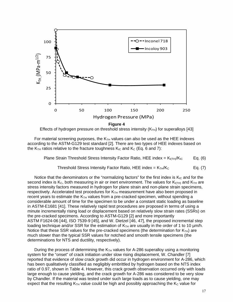
very time-consuming task. For instance, according to work performed by M. Perra [42], his hydrogen test duration was typically 5000 hours (7 months) so that an average crack velocity as small as 10-11 m/s could be resolved. According to W. Chandler [7], for some materials the KTH values are difficult to measure because of the basic problem in determination of actual crack growth versus crack branching in gaseous hydrogen environment on a fracture sample. Because of the intrinsic nature from the experimental setup to determine the KTH by using a monitoring system for the “onset” of crack initiation, theoretically it appears that the KTH measurement may be more sensitive as an HE indicator than the simple HEE index based on NTS or RA ratio. In reality, the KTH proves to be difficult to measure accurately for certain gaseous hydrogen temperature and pressure set-up conditions. According to M. Perra [42], his reported KTH values, as shown in Table 5, for superalloys such as A-286, JBK 75, and Incoloy 903®1 must be interpreted, in his own view, as “on a relative rather than an absolute basis, and the apparent KTH values within each sample group can vary as much as ±15%.” Figure 4 shows the trend behavior of KTH values as a function of hydrogen pressure for Inconel®1 718 and Incoloy 903 tested at room temperature [43]).
Table 5
Threshold stress intensity (KTH) for A-286, JBK-75 and Incolo 903 in hydrogen [Error! Bookmark not defined.]
Superalloys
Heat Treatment Yield
Strength (MPa)
Threshold (Kth) Stress Intensity, MPa.(m)1/2
(M. Perra, ref. a) H Pressure,
100 MPa H Pressure,
200 MPa
Incoloy® 903
Solutionize: 940°C/1hr/WQ. Age: 720°C/16hr.
917 n.a. 70
Solutionize: 940°C/1hr/WQ. Age: 720°C/16hr. + 620°C/8hr.
1055 33 30
JBK-75
High Energy Forging 970°C/WQ. Age: 675°C/8hr + 600°C/8hr
855 109 116
High Energy Forging 970°C/WQ. Age: 675°C/32hr.
923 69 66
Solutionize: 980°C/1hr/WQ. Age: 720°C/16hr.
717 44 47
A-286 Solutionize: 980°C/1hr/WQ. Age:
720°C/16hr. 779 n.a. 94
n.a. = not applicable a M.W. Perra. Environmental Degradation of Engineering Materials in Hydrogen, M.R. Louthan,
R.P. McNitt, R.D. Sisson (eds.), V.P.I Press, Blacksburg, VA, p. 321, 1981.
1 Inconel® and Incoloy® are registered trademarks of Inco Alloys International, Inc., Huntington, West Virginia.
17
Figure 4
Effects of hydrogen pressure on threshold stress intensity (KTH) for superalloys [43] For material screening purposes, the KTH values can also be used as the HEE indexes
according to the ASTM-G129 test standard [2]. There are two types of HEE indexes based on the KTH ratios relative to the fracture toughness KIC and KC (Eq. 6 and 7):
Plane Strain Threshold Stress Intensity Factor Ratio, HEE index = KI(TH)/KIC Eq. (6) Threshold Stress Intensity Factor Ratio, HEE index = KTH/KC Eq. (7)
Notice that the denominators or the “normalizing factors” for the first index is KIC and for the
second index is KC, both measuring in air or inert environment. The values for KI(TH) and KTH are stress intensity factors measured in hydrogen for plane strain and non-plane strain specimens, respectively. Accelerated test procedures for KTH measurement have also been proposed in recent years to estimate the KTH values from a pre-cracked specimen, without spending a considerable amount of time for the specimen to be under a constant static loading as baseline in ASTM-E1681 [41]. These relatively rapid test procedures are proposed in terms of using a minute incrementally rising load or displacement based on relatively slow strain rates (SSRs) on the pre-cracked specimens. According to ASTM-G129 [2] and more importantly ASTM F1624-06 [44], ISO 7539-9 [45], and W. Dietzel [46, 47], the proposed incremental step loading technique and/or SSR for the estimation of KTH are usually in the order of 1 to 10 µm/h. Notice that these SSR values for the pre-cracked specimens (the determination for KTH) are much slower than the typical SSR values for notched and smooth tensile specimens (the determinations for NTS and ductility, respectively).
During the process of determining the KTH values for A-286 superalloy using a monitoring
system for the “onset” of crack initiation under slow rising displacement, W. Chandler [7] reported that evidence of slow crack growth did occur in hydrogen environment for A-286, which has been qualitatively classified as negligibly embrittled by hydrogen based on the NTS index ratio of 0.97, shown in Table 4. However, this crack growth observation occurred only with loads large enough to cause yielding, and the crack growth for A-286 was considered to be very slow by Chandler. If the material was tested under such large loads as to cause yielding, one may expect that the resulting KTH value could be high and possibly approaching the KC value for
0
25
50
75
100
0 50 100 150 200 250
K TH
,(MPa
-m1/
2 )
Hydrogen Pressure (MPa)
Inconel 718
Incoloy 903

18
A-286 as tested in air. For A-286, JBK-75 and Incoloy 903, under various Solution Treated and Aged (ST+A) conditions as shown in Table 4, their KTH values are shown to be heavily affected by hydrogen. Therefore, the HEE index based on smooth RA ratio for these materials in Table 4, for heat treatment in ST+A conditions, are in qualitative agreement with the trend behavior for KTH values in hydrogen.
As an illustration for the similar behaviors between the HEE index derived from KI(TH)/KIC and
RA ratio, Figure 5 shows two HEE index trend lines for Inconel 718 tested in 34.5 MPa hydrogen pressure for a wide range of temperatures from -195 °C (-320 °F) to 540 °C (1000 °F). Surprisingly, the trend line for HEE index from RA ratio appears to be a better indicator or more sensitive than the HEE index from KI(TH)/KIC ratio, with an exception for a single data point at -195 °C where the KI(TH)/KIC ratio appears to be more sensitive to HE detection [48]. Both of these trend lines show that the maximum HEE effect occurs near room temperature, and this effect diminishes when the temperature is below -200 °C and above 550 °C.
Figure 5
Trend lines for Inconel 718 based on HEE index from KIH/KIC and RA ratio [48]
0
0.1
0.2
0.3
0.4
0.5
0.6
0.7
0.8
0.9
1
-250 -150 -50 50 150 250 350 450 550
HEE I
ndex
(Rat
io)
Temperature (°C)
KI(TH)/Kic Ratio
Smooth RA ratio

19
4.3 Low Cycle Fatigue
It is usually found that gaseous hydrogen has a considerable effect on Low Cycle Fatigue (LCF) properties for susceptible materials tested in strain-cycling controlled mode. The hydrogen degradation for LCF is also a function of strain range, as shown in Figure 6, for several PM superalloys tested at 24 °C (75 °F) in 34.5 MPa (5 ksi) hydrogen pressure. By selecting a typical strain range from 1% - 2%, the values for Cycles-to-Failure (CTF) obtained in hydrogen and in air can be qualitatively compared to indicate the severity of HEE. For example, at a typical strain range of 1.2%, the typical CTF ratios for the PM superalloys, as shown in Figure 6, are reduced nearly by a factor of 10 at room temperature [28]. Because the CTF values for fatigue testing are plotted on a log scale instead of using a linear scale similar to measuring the NTS or RA, the ratio of CTF will not be used as the typical HEE index as specified in the ASTM-G129 test standard. The typical HEE index is based on a linear scale, with a ratio ranking from 1 to 0.
Figure 6
Effects of hydrogen on strain controlled LCF of superalloys [28] Although not commonly used as the HEE index based on the ratio of CTF for LCF life
testing, the trend behavior for hydrogen embrittlement based on LCF correlates qualitatively well with the HEE index values, as shown in Table 4 for superalloys. In general, the greatest reduction in LCF life ratio is also found near room temperature for most superalloys, while at cryogenic and at relatively high temperature the LCF properties are not as severely reduced, similar to the HEE index trend lines for Inconel 718 as shown in Figure 5. When dealing with an HEE index for LCF, a comparative value of strain range should be specified since the LCF degradation is also controlled by the strain range. The LCF data under the influence of hydrogen environment for a number of superalloys are summarized in Table 6. Comparing the LCF data against the data in Table 4, superalloys such as Inconel 100, 718, 625, or Hastelloy-X®,1 which exhibit severe HEE in high hydrogen pressure at room temperature, are similarly affected in LCF tested in strain-controlled mode at room temperature. It has been found that the strain-control test mode is more sensitive to HEE than LCF testing based on the load-controlled mode.
1 Hastelloy® is a registered trademark of Union Carbide and Carbon Corporation, New York, New York.

20
Table 6 Hydrogen effects on life reduction factor under LCF loading at various temperatures
Superalloys Hydrogen Environment Low Cycle Fatigue (LCF)
Ref. Pressure (MPa) Temperature
(°C) Strain Range
(%) Life Reduction
Factor by H Inconel® 718 (STD HT) 34.5 677 1 1.1 a
Inconel® 718 34.5 25 2 1.7 a
(940 °C Sol. + Aging) 34.5 677 2 1.2
34.5 162 2 1.8
Inconel® 625 34.5 25 2 1.9 a
Hastelloy® X 34.5 25 2 2.0 a
34.5 25 1 26.0 b
IN 100 34.5 538 1 3.5
34.5 677 1 1.7
34.5 760 1 1.0
Astroloy 34.5 25 1 8.5 b
34.5 538 1 1.5
34.5 649 1 1.0
Waspaloy 34.5 25 1.2 7.5 b
34.5 538 1.2 1.4
34.5 677 1.8 1.5
34.5 25 2 11.2 b
MERL 76 34.5 538 2 3.5
34.5 649 2 1.1
34.5 760 2 1.0
Incoloy® 909 34.5 25 2 3.3 c
34.5 538 2 1.0
Incoloy® 903 (ST+ no aging) 34.5 25 2 1.3 a
34.5 760 2 1.0
Haynes 188 34.5 677 1.5 1.3 a
A-286 (annealed) 34.5 25 2 1.0 a
DS MAR-M200 34.5 677 1 5.0 a
DS MAR-M246 34.5 760 2 1.1 a
34.5 871 2 1.9
CC MAR-M246 34.5 750 0.5 1.2 a a L.G. Fritzemeier and W.T. Chandler. “Hydrogen Embrittlement-Rocket Engine Applications,” In: Superalloys, Supercomposites
and Superceramics, J.K. Tien, T. Caulfield (eds.), Materials Science Series, Academic Press, Inc., pp. 491-524, 1989 [29]. b J. E. Heine, B. A. Cowles, and J. R. Warren. “Evaluation of Powder Metallurgy Alloys in Hydrogen,” Pratt & Whitney,
FR-21186, West Palm Beach, FL, 1990 [28]. c NASA Marshall Space Flight Center unpublished data [10].

21
4.4 High Cycle Fatigue
As a general trend, it has been observed that HEE has little effect on High Cycle Fatigue (HCF) properties for many superalloys. Historically, the data for HEE effects on HCF properties were reported by J. Harris [6]. However, these tests were not typical HCF tests since the maximum cycles-to-failure were in most cases well below x104 cycles, and the maximum stresses were high, usually above the yield strengths. Typical HCF regimes are usually defined when the CTFs are at or above the x106 cycles. When the maximum stress amplitude stays significantly below YS, it is possible that no significant HCF life degradation would be observed because the majority of the test time involved in HCF testing is for crack initiation mode and not for crack propagation mode under high cyclic loading at low stress level. According to L. Fritzemeier [29], his estimation is that the HCF life can often be considered to be around 90% crack initiation and 10% crack propagation. In addition, when testing HEE using tensile smooth specimens, it is often observed that the most severe property degradation usually occurs when the tensile specimens are entering their high plastic strain regions. At the low plastic range region, the HEE effects are usually not well detected for smooth specimens. This condition may translate to the axially loaded, smooth HCF test specimens when they are subjected to the high CTF region near x106 cycles, in which region the strain range is usually very low [49]. Figure 7 shows the typical effects of HEE on both the LCF and HCF regimes for Inconel 718 superalloy, tested in 5 ksi (34.5 MPa) hydrogen pressure at room temperature. In this figure, it should be noted that the HCF regime is considered when the CTF is greater than x106 cycles.
Figure 7
Effects on HCF of Inconel 718 in 34.5 MPa hydrogen pressure at room temperature
700
800
900
1000
1100
1200
1,000 10,000 100,000 1,000,000 10,000,000
Stre
ss A
mpl
itude
(MPa
)
Cycles to Failure
Helium (34.5 MPa)
Hydrogen (34.5 MPa)

22
4.5 Crack Growth Rate
The hydrogen data for sustained-load crack growth rates (da/dt) are not as common as the cyclic-load crack growth rates (da/dN) for several superalloys. The HEE effects for cyclic crack growth rates (da/dN) as a function of stress intensity factor range (∆K) of several superalloys at 5 ksi (34.5 MPa) to 7 ksi (48.2 MPa) are shown in Figure 8 [50]. With the exception for Mar-M-246 from conventional cast, which was tested at 538 °C (1000 °F), the most rapid crack growth at room temperature was observed for Inconel 718 that was solution treated at 940 °C (1725 °F) and then aged (STA 2 condition). Following Mar-M-246, the third fastest cyclic crack growth rate is Inconel 718, labeled as STA 1 heat treatment, which was solutionized at 1038 °C (1900 °F) and aged. The least HE effect is with cast Inconel 718 in annealed conditions. Therefore, heat treatment can change the HE behaviors significantly for certain superalloys, such as Inconel 718, with complex and precipitation hardening phases. These crack growth rates are non-linear curves and also plotted on a log scale as a function of either K or ΔK values; therefore, these data are not commonly used as the typical HEE index as specified in the ASTM-G129 test standard. The typical HEE index is based on a linear scale, with a property ratio ranking from 1 to 0.
Figure 8
HEE effects for cyclic crack growth rates (da/dN) for several superalloys [50]

23
4.6 Creep Rupture
For high-temperature applications, creep resistance over extended periods of time is a very important design property for superalloys. Since plastic strain is accumulated over time by the process of creep, this effect is pertinent to the design of complex shaped turbine blades, which are machined to tight tolerances with respect to the inside dimensions of the turbine housings. Historic data for creep resistance of superalloys in hydrogen environment for aerospace applications are somewhat limited because most rocket engine applications have a relatively short design life at high temperature. Even though the available data for creep is not extensive, it reveals a similar trend that, if the common HEE indexes are degraded by hydrogen near the vicinity of room temperature, then it is likely that the creep properties will be affected by hydrogen at high temperature. Some significant but limited studies of creep properties for superalloys in hydrogen were performed by Harris for aerospace [51, 9, 52], and by Bhattacharyya for automotive applications [53, 54]. For creep rupture, a common time-temperature parameter used to present the rupture-stress is the Larson-Miller (L.M.) Parameter, which is expressed in the following form (Eq. 8):
P (L.M.) = T [C + Log (t)] Eq. (8)
Where: T = test temperature (in K or R), t = stress-rupture time (in hour), C = constant
usually in the order of 20. According to the L.M. parameter, at a given stress level the log time to stress rupture plus a constant of the order of 20, multiplied by the test temperature remains a constant for a given material. Several P (L.M.) values for creep-rupture behaviors of superalloys, tested in high-pressure and high-temperature hydrogen, were documented by L. Fritzemeier [29]. One example for the P (L.M.) for creep rupture of Inconel 718, solutionizing at 1920°F (1050°C), is given in Figure 9.
Figure 9
Larson-Miller Parameter for creep-rupture of Inconel 718 tested in hydrogen [29]
0
100
200
300
400
500
600
700
800
900
33.0 34.0 35.0 36.0 37.0 38.0 39.0
Ruptu
re St
ress
(MPa
)
P (L.M) = 1.8 x T (K deg)(20 + LOG t) x 10-3
Helium (34.5 MPa)
Hydrogen (34.5 MPa)

24
Since creep testing is a long-termed test involving inelastic strain, considerable reductions of creep stress-rupture strengths are expected for highly susceptible materials. Additionally, the reduction in time-to-failure without significant creep ductility loss is also possible. In the initial stage, or primary creep, the creep strain rate is relatively high; therefore, no significant effect of hydrogen-enhanced deformation is observed. However, during the secondary stage or the stage of slow but steady-state creep rate, the primary observation for creep in hydrogen environment is an increase in creep strain rate, leading to the reduction in time-to-rupture. This action, causing hydrogen-enhanced deformation in a later stage of creep deformation, thus reduces the rupture life under creep strain testing. An example of this effect is shown in Figure 10 for the Directional Solidification (DS) of MAR-M246 superalloy tested at 760 °C (1400 °F) in 5 ksi (34.5 MPa) hydrogen pressures. The creep test was conducted with 110 ksi (758 MPa) stress level [55]. However, it has been found that the total creep ductility for superalloys is not affected very much by hydrogen.
The reduction in time-to-rupture, or the total rupture life, without significant creep ductility
loss is possible because the dissolved hydrogen in the metals can increase the mobility of glide dislocations at elevated temperatures. This dislocation climb mechanism does not tend to create localized strain; therefore, it would not be susceptible to a condition for high hydrogen concentrations near the crack tips. The net effect is that an increased creep strain rate would lead to a reduction of rupture life, without the loss of total rupture ductility in hydrogen environment at high temperature.
Figure 10
Creep stress-rupture of directionally solidified MAR-M246 in hydrogen at 758 MPa stress level [55]
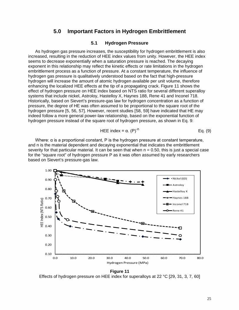
25
5.0 Important Factors in Hydrogen Embrittlement
5.1 Hydrogen Pressure
As hydrogen gas pressure increases, the susceptibility for hydrogen embrittlement is also increased, resulting in the reduction of HEE index values from unity. However, the HEE index seems to decrease exponentially when a saturation pressure is reached. The decaying exponent in this relationship may reflect the kinetic effects or rate limitations in the hydrogen embrittlement process as a function of pressure. At a constant temperature, the influence of hydrogen gas pressure is qualitatively understood based on the fact that high-pressure hydrogen will increase the amount of atomic hydrogen available per unit volume, therefore enhancing the localized HEE effects at the tip of a propagating crack. Figure 11 shows the effect of hydrogen pressure on HEE index based on NTS ratio for several different superalloy systems that include nickel, Astroloy, Hastelloy X, Haynes 188, Rene 41 and Inconel 718. Historically, based on Sievert’s pressure-gas law for hydrogen concentration as a function of pressure, the degree of HE was often assumed to be proportional to the square root of the hydrogen pressure [5, 56, 57]. However, recent studies [58, 59] have indicated that HE may indeed follow a more general power-law relationship, based on the exponential function of hydrogen pressure instead of the square root of hydrogen pressure, as shown in Eq. 9:
HEE index = α. (P)-n Eq. (9)
Where: α is a proportional constant, P is the hydrogen pressure at constant temperature,
and n is the material dependent and decaying exponential that indicates the embrittlement severity for that particular material. It can be seen that when n = 0.50, this is just a special case for the “square root” of hydrogen pressure P as it was often assumed by early researchers based on Sievert’s pressure-gas law.
Figure 11
Effects of hydrogen pressure on HEE index for superalloys at 22 °C [29, 31, 3, 7, 60]
0.10
0.20
0.30
0.40
0.50
0.60
0.70
0.80
0.90
1.00
0.0 10.0 20.0 30.0 40.0 50.0 60.0 70.0 80.0
HEE I
ndex
(NTS
Rat
io)
Hydrogen Pressure (MPa)
Nickel (ED)
Astroloy
Hastelloy X
Haynes 188
Inconel 718
Rene 41

26
5.2 Temperature
It has been observed that HEE can occur over a wide range of temperatures; however, it is most severe in the vicinity of room temperature for many materials. Based on the so-called hydrogen trapping model, a hydrogen trapping may be considered as the binding of hydrogen atoms to impurities, structure defects, or microstructure constituents in the alloy. Qualitatively, the binding energy and the diffusivity of hydrogen in the trapping models have been proposed to explain why hydrogen embrittlement is most severe near room temperature and becomes less severe or negligible at higher or lower temperature range [61]. At lower temperatures, the diffusivity of hydrogen is too sluggish to fill sufficient hydrogen traps; but at high temperatures, hydrogen mobility is enhanced, and trapping is diminished. At high strain rates, fracture may proceed without assistance of hydrogen, because the slow mobility of hydrogen is not sufficient to maintain a hydrogen-trapped atmosphere slightly ahead of the fast advancing crack tip. Figure 12 shows the hydrogen embrittlement effect of several steel alloys as a function of temperature. It is found that many austenitic stainless steels (Fe-Ni-Cr) are mostly sensitive to hydrogen embrittlement at a temperature range from -150 °C to +150 °C.
Figure 12
Effects of temperature on HEE index for selected steels [62]
The HEE of some superalloys can occur over a wide range of temperatures from cryogenic to at least 800 °C (1500 °F), but it is most severe in the vicinity of room temperature. This is an important factor to consider for safe design, since superalloys are often used for high-temperature applications. This temperature effect for superalloys is unlike some austenitic stainless steels (Fe-Ni-Cr), which are mostly sensitive to HE at lower temperature range. It is possible that some iron-based superalloys, because their compositions are evolved from
-273 -173 -73 26 126 (-460) (-280) (-100) (80) (260)
Test Temperature, C (F)
HEE I
ndex
, (Ra
tio o
f pla
stic e
long
atio
n in
H2/
Air)
*Cat
hodi
cally
char
ged.
** C
harge
d at 6
1 MPa
and 5
00 C
for 3
6 hrs.
Ϯ Cha
rged
with
Deu
teriu
m at
69 M
Pa an
d 345
C fo
r 3 w
eeks
.

27
common stainless steel, would tend to have a lower temperature range for hydrogen embrittlement. However, this assumption may not be applied to some nickel and cobalt-based alloys. For instance, Figure 13 shows the HEE index, based on area reduction ratio, for three nickel-based superalloys: Inconel 718, EP99, and EP741. The HEE index for Inconel 718 is most severe near the vicinity of room temperature [29]. However, significant hydrogen embrittlement (e.g., HEE index = 0.60) is still evident for Inconel 718 even at temperature as high as 425 °C (800 °F). As for EP99 and EP741, it is apparent that the hydrogen embrittlement effects are more severe near 485 °C (905 °F) rather than near room temperature [63]. Similarly, the most severe temperature for HEE index, based on NTS ratio, occurs at 538 °C (1000 °F) rather than near the vicinity of room temperature for Astroloy, Merl 76, IN100 and Waspaloy, as shown in Figure 14 [28]. Experimental data for nickel-based Udimet 700® 1 superalloy has shown that its extent of hydrogen embrittlement, as a function of temperature, is far greater at high temperature than for any other superalloy [64].
At high temperature, with sufficient thermal activation energy, there is a potential for HRE, in
which hydrogen atoms are chemically reacted with certain material’s constituents or impurities at the grain boundaries. The HRE type of embrittlement can additionally enhance the appearance of HEE at high temperature, which one would not anticipate near ambient temperature.
Figure 13
Effects of temperature on HEE index for selected nickel-based superalloys [29, 63]
1 Udimet® is a registered trademark of Special Metals, Inc., New Hartford, New York.
0
0.2
0.4
0.6
0.8
1
-300 -100 100 300 500 700 900
HEE I
ndex
(Are
a Red
uctio
n Ra
tio)
Temperature (°C)
Inconel 718
EP 99
EP 741

28
Figure 14
Effects of temperature on HEE index for selected PM superalloys [28]
5.3 Heat Treatment and Product Forms Heat treatment and product forms can have a profound effect on the degree of HE for
certain types of materials with complex microstructures. In general, wrought and PM processes have been found to have a slightly less influence by high-pressure hydrogen environment than cast superalloys with similar compositions and heat treatment [29]). Table 7 shows the influence of heat treatment and product forms on the HEE index, based on NTS ratio, for five different types of superalloys tested at room temperature with pressure at 5 ksi (34.5 MPa). For Astroloy in standard heat treatment, a moderate improvement for the HEE index can be achieved when this material is in wrought (PM) product form instead of cast. For IN100 and Waspaloy, both in PM product form, different heat treatment conditions give rise to a small change in HEE index. However, the effect of heat treatment becomes very profound for Inconel 718 in wrought form. Choosing between 1750°F (955°C) or 1900°F (1037°C) as solution annealing temperature, Inconel 718 can become extremely embrittled (HEE index = 0.53) or slightly embrittled (HEE index =0.92) by high-pressure hydrogen gas, respectively. This phenomenon may be related to the precipitation of the delta (δ) phase at the grain boundaries when treating at a lower solution temperature [65]. It is obvious that HEE susceptibility of materials within a given alloy system can vary significantly, and the majority of these superalloys have been found to be very susceptible to HEE. For superalloys A-286, JBK-75, and Incoloy 903, the data trend reveals an important factor that heat treatment can drastically affect the HEE behaviors for some materials. In this case, the ST+A conditions for these materials would enhance the HEE effects much more than Solution Treated (ST) without Aging. Typical ST+ A conditions are given in Table 8 for JBK-75, A-286, and Incoloy 903.
Because Inconel 718 has been used extensively, detailed heat treatment studies were
conducted by Walter and Chandler [3, 19] for applications in high-pressure hydrogen environment. Table 9 presents the results of HEE index for Inconel 718 in combinations of five different heat treatments and product forms, which also include weld and Heat Affected Zone
0.70
0.75
0.80
0.85
0.90
0.95
1.00
1.05
0 100 200 300 400 500 600 700 800
HEE I
ndex
(NTS
ratio
)
Temperature (°C)
Astroloy (PM)MERL 76 (PM)IN 100 (PM)Waspaloy (PM)

29
(HAZ) materials. In all heat treatment cases, Inconel 718 in plate form appears to be less influenced by hydrogen than in rolled-bar and forging forms. Microstructure analysis shows that heat treatment A produced a fine-grained structure with discontinuous Ni3Nb intermetallic delta (δ) phase for the plate product, which was the least embrittled by hydrogen. However, this same heat treatment A in rolled-bar and forged products resulted in larger grains and continuous intergranular Ni3Nb precipitates that formed a preferential fracture path, resulting in a structure that was the most embrittled in hydrogen environment.
Similar to A286, JBK-75 superalloy, when solution annealed with no aging, is negligibly
embrittled by hydrogen at 5 ksi (34.5 MPa) pressure. Heat treatment study has shown that aging conditions would dramatically increase the yield strength and ultimate tensile strength for JBK-75. However, such aging conditions would make JBK-75, A-286 and Incoloy 903 become very susceptible to HE, as shown in Table 8.
Table 7
Effects of heat treatment & product forms on HEE index for superalloys
Superalloys Heat Treatment Product Form
HEE Index, (NTS)
H Pressure
MPa (ksi)
Temp. °C (°F) Ref.
Astroloy® Standard cast 0.90
34.5 (5) 22 (72) a
Standard PM 0.94 b MATE (proprietary HT) PM 0.98 b
IN 100 Standard PM 0.94
34.5 (5) 22 (72) b
DTP (proprietary HT) PM 0.89 b
Inconel® 718 Solutionized + Aging wrought 0.54
34.5 (5) 22 (72) c
Solutionized + No aging wrought 0.83 c
MERL 76 Standard wrought 0.85
34.5 (5) 22 (72) d
Standard PM 0.96 b
Waspaloy® Standard PM 0.95
34.5 (5) 22 (72) b
Forged at Sub-Solvus temp. PM 0.90 b a H.R. Gray and J.P. Joyce. “Hydrogen Embrittlement of Turbine Disk Alloys,” In: Effect of Hydrogen on
Behavior of Materials, A.W. Thompson & I.M. Bernstein (eds.), AIME Publication, pp. 578-588, 1976 [60]. b J. E. Heine, B. A. Cowles, and J. R. Warren. “Evaluation of Powder Metallurgy Alloys in Hydrogen,” Pratt &
Whitney, FR-21186, West Palm Beach, FL, 1990 [28]. c W.T. Chandler. “Hydrogen Environment Embrittlement and Its Control in High Pressure Hydrogen/Oxygen
Rocket Engines,” In: Advanced Earth-to-Orbit Propulsion Technology, NASA Conference Publication 2437, R. J. Richmond & S.T. Wu (eds.), vol. 2, pp. 618-634, 1986 [3].
d L.G. Fritzemeier and W.T. Chandler. “Hydrogen Embrittlement-Rocket Engine Applications,” In: Superalloys, Supercomposites and Superceramics, J.K. Tien, T. Caulfield (eds.), Materials Science Series, Academic Press, Inc., pp. 491-524, 1989 [29].

30
Table 8 Effects of solution treatment and aging time on superalloys
Superalloys Heat Treatment Aged Time (hr)
HEE Index H pressure,
(MPa)
Test Temp.
°C
Strengths in Air, (MPa) Ref.
RA Elong YS UTS
JBK-75
Solution Treated @
980°C/1 hr./WQ. Aged @ 720°C as a function of aging
time
0 0.96 0.97
172 22
241 620
a
4 0.39 0.71 565 1058
8 0.41 0.69 632 1091
12 0.41 0.76 672 1131
16 0.46 0.75 716 1130
A-286
Solution Treated @ 927°C/2hr/WQ. Aged @ 720°C as a function of aging
time
0 0.97
n.a.
Thermal charged,
200°C/200 hr. at 69
MPa.
22
n.a.
b
0.5 0.97 975
1 0.9 1040
2 0.74 n.a. 1085
4 0.64 1075
16 0.51 1130
50 0.43 1090
100 0.42 1065
Incoloy 903
Solution Treated @
950°C/1hr./WQ. Aged @ 620°C as a function of aging
time
0 1.00
n.a.
Thermal charged,
300°C/336 hr. at 10
MPa.
22
n.a. n.a.
c
4 0.80 750 980
8 0.78 890 1120
12 0.70 940 1160
16 0.62 985 1220 a B.C. Odegard and A.J. West. “The Effect of η-Phase on the Hydrogen Compatibility of a Modified A-286 Superalloy:
Microstructure and Mechanical Properties Observations,” In: Hydrogen Effects in Metals, I.M. Bernstein, A.W. Thompson (eds.), AIME Publication, pp. 597-606, 1980 [66].
b J.A. Brooks and A.W. Thompson. “Microstructure and Hydrogen Effects on Fracture in the Alloy A-286,” Metall. Trans. A, Vol. 24A, pp. 1983-1991, 1993 [36].
c Wang, A.C., et al. “Effect of Strengthening Particle Size on Hydrogen Performance of Incoloy 903,” J. Mat. Sci. Lett., Vol. 13, pp. 1187-1189, 1994 [67].

31
Table 9 Effects of heat treatment and product forms for Inconel® 718 superalloy [3, 19]
Solution Treatment and Aging Schedule for Inconel 718 Product Form
HEE Index, (NTS)
H Pressure
(MPa) Temp (°C)
Strengths in Helium (MPa) Ref.
NTS YS UTS
HEAT TREATMENT A: 940°C/1hr (solutionized) +
720°C/8hr (1st aging) + 620°C/8hr (2nd aging).
Rolled Bar 0.54
34.5 22
1952 1124 1393
a, b
Forging 0.59 2000 1097 1366
Plate 0.86 1979 1097 1414
Plate (Weld Metal) 0.79 1421 1034 1193
Plate (Weld HAZ) 0.63 1828
HEAT TREATMENT B: 940°C/1hr (solutionized) + 815°C/10hr (1st aging) + 650°C/8hr (2nd aging).
Rolled Bar 0.70
34.5 72
1655 876 1255
Forging 0.57 1745 855 1228
Plate 0.86 1731 917 1303
Plate (Weld Metal) 0.78 1241 869 1145
Plate (Weld HAZ) 0.75 1393
HEAT TREATMENT C: 1050°C/0.3hr (solutionized) +
760°C/10hr (1st aging) + 650°C/8hr (2nd aging).
Rolled Bar 0.71
34.5 22
2221 1110 1345
Forging 0.76 2338 1166 1366
Plate 0.77 2207 1152 1407
Plate (Weld Metal) 0.56 1848 1138 1372
Plate (Weld HAZ) 0.72 2076
HEAT TREATMENT D: 1025°C/10 min. (solutionized) +
no aging Rolled Bar 0.83 34.5 22 1124
HEAT TREATMENT E: 1025°C/10 min. (solutionized) +
760°C/9.5hr (1st aging) + 650°C/9hr (2nd aging).
Rolled Bar 0.71
34.5 22
2200 1152 1379
Forging 0.70 2221 1166 1393
Plate 0.75 2200 1172 1428
Plate (Weld Metal) a W.T. Chandler. “Hydrogen Environment Embrittlement and Its Control in High Pressure Hydrogen/Oxygen Rocket Engines,” In:
Advanced Earth-to-Orbit Propulsion Technology, NASA Conference Publication 2437, R. J. Richmond & S.T. Wu (eds.), vol. 2, pp. 618-634, 1986 [3].
b R.J. Walter and W.T. Chandler. “Influence of Gaseous Hydrogen on Metals-Final Report,” Rocketdyne, Canoga Park, CA, NASA-CR- 124410, October 1973 [19].
5.4 Alloy Compositions
The effects of alloy compositions on hydrogen embrittlement for certain groups of superalloys and austenitic stainless steels, which are in the simple form of the Fe-Ni-Cr ternary alloy system, are examined together in this section. Obviously, the hydrogen effect based on alloy composition alone is difficult to isolate separately from the influence of other factors such as microstructure, phases and thermal processes. It is important to recognize that HE effects based on compositions of many high-strength engineering alloys and superalloys have been studied extensively because these materials are useful for the industry; however, these engineering alloys are sometimes the least suitable for the purpose of discovering the general scientific principles because of their inherit complexity in the compositions and microstructures [68]. However, a comparative study based on composition may be possible, providing that these alloys are produced or selected intentionally to share relatively common features among each other such as being a solid solution, having similar alloying phase, heat treatment, product forms, etc.
For austenitic stainless steels, experimental tests conducted at -50 °C (-58 °F) by T. Michler
[69] for a large number of test samples shows that nickel content is the main factor that controls

32
the HE effect. Specifically, when Ni contents are above 12.5 wt%, the HE becomes negligible. In another study, Michler [70] conducted HEE testing for several Fe-Ni-Cr austenitic steels at different temperature and pressure combinations, which again showed that HE becomes negligible when Ni contents is above 11.5 wt%. Similarly, the work of Fe-Ni-Cr stainless steel from Caskey [62] reveals a wider range of Ni, but provides similar conclusion about Ni contents when it is above 12.5 wt%. From these studies, it can be shown that HE becomes negligible when Ni contents are from 12.5wt% to 35wt% for most austenitic stainless steels in the Fe-Ni-Cr system, where Cr remains in the range of 16 to 20 wt%.
The alloy compositional works from Caskey and Michler for Fe-Ni-Cr stainless steels could
logically extend into higher ranges of Ni to examine the compositional effects for some selected superalloys. However, for a comparative study these selected superalloys were intentionally heat treated under solution-annealed conditions so that the effects of the precipitate phases are significantly reduced or eliminated. For several Fe-Ni-Cr based superalloys, with their Ni contents varying from 25% to 80 wt%, Table 10 and Figure 15 show the HE effects with the HEE index based on NTS and tensile ductility ratios. Interestingly, the trend for hydrogen embrittlement of these superalloys, as a function of Ni contents, is matched very closely with the trend line for Fe-Ni-Cr austenitic stainless steels. That is, HE becomes negligible when Ni contents are from 12.5% to 35%. Moreover, the influence of minor elements seem to have only a minor effect on hydrogen embrittlement, and Ni content is the main factor that controls the HE effect for Fe-Ni-Cr superalloys under solution-annealed condition.
Table 10
HEE Index for Fe-Ni-Cr superalloys and stainless steels as a function of Ni content (wt.%)
Superalloys Heat Treatment
Product Form Ni Fe Cr HEE
Index HEE Type Ref.
A286 annealed wrought 26.0 54.0 15.0 0.98 NTS a JBK-75 annealed wrought 30.0 50.0 15.0 0.98 NTS b
Incoloy 801 annealed wrought 32.0 44.5 20.5 0.87 elong (IHE) c
Incoloy 800 annealed wrought 32.5 46.0 21.0 0.94 elong d,c Incoloy 802 annealed wrought 32.5 46.0 21.5 0.99 NTS b
Carpenter 20-Cb3 annealed wrought 34.0 42.5 20.0 0.98 elong d Inconel 706 annealed wrought 41.5 40.0 16.0 0.82 NTS e
Incoloy 825 annealed wrought 42.0 21.5 22.0 0.75 elong (IHE) c
Inconel X750 annealed wrought 73.0 7.0 16.0 0.26 NTS b Inconel 600 annealed wrought 76.0 8.0 15.5 0.23 RA (IHE) f
Inconel MA 754 annealed wrought 78.5 0.0 20.0 0.19 RA e
Austen. Stainless Steel annealed wrought 8.1 16-18 0.23 RA T. Michler Austen. Stainless Steel annealed wrought 8.3 0.26 RA (g,h) Austen. Stainless Steel annealed wrought 8.6 0.34 RA Austen. Stainless Steel annealed wrought 8.8 0.28 RA Austen. Stainless Steel annealed wrought 9.9 0.66 RA Austen. Stainless Steel annealed wrought 10.1 0.55 RA Austen. Stainless Steel annealed wrought 10.2 0.48 RA Austen. Stainless Steel annealed wrought 10.5 0.48 RA Austen. Stainless Steel annealed wrought 11.2 0.64 RA Austen. Stainless Steel annealed wrought 11.2 0.85 RA Austen. Stainless Steel annealed wrought 12.5 0.96 RA Austen. Stainless Steel annealed wrought 12.8 0.98 RA Austen. Stainless Steel annealed wrought 13.0 16-18 0.98 RA G. Caskey Austen. Stainless Steel annealed wrought 14.0 0.98 RA (i) Austen. Stainless Steel annealed wrought 18.0 0.98 RA

33
Superalloys Heat Treatment
Product Form Ni Fe Cr HEE
Index HEE Type Ref.
Austen. Stainless Steel annealed wrought 19.0 0.98 RA Austen. Stainless Steel annealed wrought 25.0 0.97 RA Austen. Stainless Steel annealed wrought 32.0 0.96 RA
a W.T. Chandler and R.J. Walter. “Testing to Determine the Effect of High Pressure Hydrogen Environments on the Mechanical Properties of Metals,” In: Hydrogen Embrittlement Testing, L. Raymond (ed.), ASTM Special Technical Publication, STP 543, pp. 170-197, June 1972 [7].
b NASA Marshall Space Flight Center unpublished data [10] c D.L. Graver, “Hydrogen Permeation and Embrittlement of Some Nickel Alloys “, In: Corrosion of Nickel-Base Alloys,
R.C. Scraberry, eds., ASM Pub., 1984, pp. 79-85 [71]. d G.R. Caskey, Jr., “Hydrogen Compatibility Handbook for Stainless Steels,” E.I. du Pont & Co., Report DP-1643,
June 1983 [8]. e L.G. Fritzemeier and W.T. Chandler. “Hydrogen Embrittlement-Rocket Engine Applications,” In: Superalloys,
Supercomposites and Superceramics, J.K. Tien, T. Caulfield (eds.), Materials Science Series, Academic Press, Inc., pp. 491-524, 1989 [29].
f M. Cornet, et al. “Hydrogen Embrittlement of Ultra-Pure Alloys of the Inconel 600 Type: Influence of the Additions of Elements (C, P, Sn, Sb),” Metall. Trans. A, Vol. 13A, 1982, pp. 141-144 [72].
g T. Michler and J. Naumann. “Hydrogen Environment Embrittlement of Austenitic Stainless Steels at Low Temperature,” Inter. Jour. Hydrogen Energy, Vol. 33, pp. 2111-2122, 2008 [69].
h T. Michler, A. Yukhimchuk, and J. Naumann. “Hydrogen Environment Embrittlement Testing at Low Temperature and High Pressure,” Corrosion Science, Vol. 50, pp. 3519-3526, 2008 [70].
i G.R. Caskey. “Hydrogen Effects in Stainless Steel,” In: Hydrogen Degradation of Ferrous Alloys, R.A. Oriani, J. P. Hirth, M. Smialowski (eds.), Noyes Publications, New Jersey, pp. 822-862, 1985 [62].
Figure 15
HEE Index for Fe-Ni-Cr superalloys and stainless steels as a function of Ni content (wt.%) (Data are from references in Table 10)
0
0.1
0.2
0.3
0.4
0.5
0.6
0.7
0.8
0.9
1
1.1
0.0 10.0 20.0 30.0 40.0 50.0 60.0 70.0 80.0 90.0
HEE
INDE
X
Nickel (wt.%)
Ni-Fe-Cr based Superalloys
Austenitic Stainless Steels

34
5.5 Surface Finish
The sensitivity of the HEE index for susceptible materials can also be slightly affected by the surface finish on HE test coupons. This is because gaseous hydrogen has a significant influence on the surface’s microcrack initiation and growth behavior, particularly when relatively large surface flaws exist on a susceptible material exposed in high-pressure hydrogen environment.
Therefore, some care must be taken in specimen preparation and component fabrication for
surface machining and finishing. Internal cracks by HE can initiate and propagate with little macroscopic evidence of corrosion or damaging features and no warning as catastrophic failure approaches. These internal cracks initiate frequently at surface flaws that are either preexisting or formed during service in hydrogen environment. The flaw features may include sharp corners, grooves, laps, or burrs resulting from fabrication processes.
5.6 Grain Directions and Crystal Orientations Limited numbers of studies were taken to determine the influence of HE on the grain
directions of wrought superalloys. Table 11 shows the HEE index, based on NTS ratio, for transverse and longitudinal grain direction of wrought Oxide-Dispersed Strengthening (ODS) superalloys in 5 ksi (34.5 MPa) hydrogen pressures at 72°F (22°C). The results show that grain directions have a small effect on HEE, with longitudinal being slightly less influenced by hydrogen than the transverse direction. In another study of grain orientations from cast superalloys, using directionally solidified and Conventionally Cast (CC) processes, the MAR-M246 superalloy shows that with the higher microstructure-uniformity process obtained from the DS, it tends to be slightly less influenced by hydrogen than the CC process [55]. HEE effects on grain directions have not been extensively studied for wrought superalloys; however, the general trends indicate that the difference in HE effect is relatively small for polycrystalline wrought alloys due to the grain directions.
Table 11
HEE Effects on grain direction of selected wrought superalloys [29]
SUPERALLOYS Grain Direction HEE Index (NTS)
H Pressure MPa (ksi)
Temp. °C (°F)
Alloy Based Process Ref.
MA 754 Transverse 0.94 34.5 (5) 22 (72)
Nickel ODS
a
Longitudinal 0.96 34.5 (5) 22 (72)
MA 956 Transverse 0.34 34.5 (5) 22 (72)
Iron ODS Longitudinal 0.58 34.5 (5) 22 (72)
MA 6000 Transverse 0.92 34.5 (5) 22 (72)
Nickel ODS Longitudinal 0.86 34.5 (5) 22 (72)
a L.G. Fritzemeier and W.T. Chandler. “Hydrogen Embrittlement-Rocket Engine Applications,” In: Superalloys, Supercomposites and Superceramics, J.K. Tien, T. Caulfield (eds.), Materials Science Series, Academic Press, Inc., pp. 491-524, 1989 [29].
Historic data for the influence of hydrogen embrittlement on the crystallographic orientation
of single crystal superalloys are somewhat limited. A preliminary study of single crystal PWA 1480E was conducted by K. Bowen [34], based on the HEE index for NTS ratio, in hydrogen 5 ksi (34.5 MPa) at 72°F (22°C) and 1600°F (875°C). At very high temperature, the hydrogen effect is diminished as expected, without showing a definite trend for HE based on crystal directions. However, Table 12 shows that the <111> crystal direction retains the best and the <001> direction gives the worst HEE index when tested at room temperature. Evidently, crystal orientations from single crystal materials do have a strong effect on HE in comparison to polycrystalline materials with similar composition.

35
Table 12
HEE Effects on crystal orientation for PWA 1480E superalloy [29, 34] Superalloys
(Single Crystal) Crystal
Orientation HEE
Index (NTS)
NTS in Helium, MPa (ksi)
H Pressure MPa (ksi)
Temp. °C (°F)
Ref.
PWA 1480E
<001> 0.57 1531.0 (222.0)
34.5 (5) 22 (72) a, b
<111> 0.88 1566.5 (227.2) <112> 0.73 1633.4 (236.9) <110> 0.79 1692.1 (245.4) <223> 0.76 1618.2 (234.7) <123> 0.74 1672.7 (242.6) <013> 0.65 1583.0 (229.6)
PWA 1480E
<111> 0.99 1308.6 (189.8)
34.5 (5) 870 (1600) b
<112> 0.94 1297.6 (188.2) <100> 0.90 1442.4 (209.2) <110> 1.07 1168.7 (169.5) <223> 1.01 1225.2 (177.7) <123> 0.97 1291.4 (187.3) <013> 0.97 1319.6 (191.4)
a L.G. Fritzemeier and W.T. Chandler. “Hydrogen Embrittlement-Rocket Engine Applications,” In: Superalloys, Supercomposites and Superceramics, J.K. Tien, T. Caulfield (eds.), Materials Science Series, Academic Press, Inc., pp. 491-524, 1989 [29].
b K. Bowen, P. Nagy, and R. Parr. “The Evaluation of Single Crystal Superalloys for Turbopump Blades in the SSME,” AIAA-1986-1477, 22nd Joint Propulsion Conference, June 16-18, 1986 [34].
6.0 Prevention and Control Methods for Hydrogen Damage
6.1 General Guidelines
Figure 16A depicts the overlapped regions for HEE, IHE and HRE that are created by the intersections of three circles representing the influence factors from the material type, hydrogen environment, and the applied stress. By reducing or removing only one of these three factors, it is possible to alter the hydrogen damaging effects for many susceptible materials, as shown in Figure 16B. This concept is the general guideline for prevention and control methods for hydrogen damage as listed in this section.
For the HEE and IHE type, the influence of the applied stress is an important factor and the
stress should be reduced or removed when possible to control the embrittlement effects. In contrast, the HRE type is formed by the intersection between hydrogen and material, and it can be an irreversible damage resulting without the influence of an applied stress. In theory, the hydrogen damaging effects can be altered by reducing or removing only one of these three main factors. In practice, it is often difficult to be able to completely eliminate or remove only one of these three influential factors; therefore, it is advisable to find a combination of methods that would work best for reducing the influence of all three factors. Several practical techniques for controlling the material type, hydrogen environment, and applied stress are briefly suggested in the following sections.
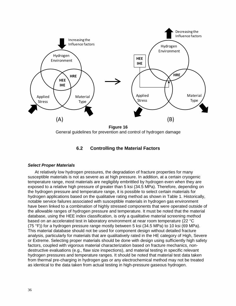
36
Figure 16
General guidelines for prevention and control of hydrogen damage
6.2 Controlling the Material Factors
Select Proper Materials At relatively low hydrogen pressures, the degradation of fracture properties for many
susceptible materials is not as severe as at high pressure. In addition, at a certain cryogenic temperature range, most materials are negligibly embrittled by hydrogen even when they are exposed to a relative high pressure of greater than 5 ksi (34.5 MPa). Therefore, depending on the hydrogen pressure and temperature range, it is possible to select certain materials for hydrogen applications based on the qualitative rating method as shown in Table 1. Historically, notable service failures associated with susceptible materials in hydrogen gas environment have been linked to a combination of highly stressed components that were operated outside of the allowable ranges of hydrogen pressure and temperature. It must be noted that the material database, using the HEE index classification, is only a qualitative material screening method based on an accelerated test in laboratory environment at near room temperature (22 °C (75 °F)) for a hydrogen pressure range mostly between 5 ksi (34.5 MPa) to 10 ksi (69 MPa). This material database should not be used for component design without detailed fracture analysis, particularly for materials that are qualitatively rated in the HE category of High, Severe or Extreme. Selecting proper materials should be done with design using sufficiently high safety factors, coupled with vigorous material characterization based on fracture mechanics, non-destructive evaluations (e.g., flaw size inspections), and material testing in specific relevant hydrogen pressures and temperature ranges. It should be noted that material test data taken from thermal pre-charging in hydrogen gas or any electrochemical method may not be treated as identical to the data taken from actual testing in high-pressure gaseous hydrogen.
HydrogenEnvironment
AppliedStress
MaterialType
HEEIHE
HRE
(A)
Increasing theInfluence factors Hydrogen
Environment
AppliedStress
MaterialType
HRE
HEEIHE
(B)
Decreasing theInfluence factors

37
Select Steels Using Nelson Curve for Corrosive Environment At certain elevated temperatures, atomic hydrogen can react internally with certain types of
elements and compounds in the material. This form of Hydrogen Reaction Embrittlement (HRE can occur in carbon steels. The common reaction is between hydrogen and iron-carbides to form methane gas (CH4). Deep within the bulk of the material, the formation and migration of CH4 molecules, usually concentrated at grain boundaries and metallurgical features such as inclusions, impurities, trap elements, and defects, can lead to brittle rupture through the formation of voids, blisters and a network of discontinuous microcracks. Moreover, because the carbide phase is a reactant in the mechanism, its depletion in the vicinity of generated defects serves as direct evidence of the HRE mechanism itself. The HRE sensitivity depends on the amount of carbon or carbide in the alloy, the hydrogen concentration, gas pressure, and temperature usually in the range of 200 to 600 °C (400 to 1110 °F). Alloy steels with stable carbides such as chromium-carbides are less susceptible to this form of hydrogen attack due to the greater stability of Cr3C versus Fe3C found in carbon steels. However, as the pressure and temperature of hydrogen environment increases, a greater amount of these alloying additions are required to minimize such attack.
The addition of chromium and molybdenum are beneficial alloying elements for many
carbon and low-alloy steels to prevent the HRE from decarburizing. For example, 2.25Cr-1Mo steel undergoes some decarburization in high pressure and temperature hydrogen, but it is less likely to fissure than carbon steels. However, as the conditions increase in severity, higher-alloy steels such as 5Cr-0.5Mo or 9Cr-1Mo may be required. Figure 17 shows the Nelson curve as a selection guide for the operating limits of certain types of steels in hydrogen service from the influence of HRE effects [73].
Figure 17
The Nelson curve defining safe upper limits for steels in hydrogen service [73]

38
Select Proper Thermo-mechanical Treatment Heat treatment can have a profound effect on the degree of HE, particularly for materials
with complex microstructures. However, these general trends can often be influenced by the particular grain sizes and phases resulting from solution and aging heat treatments. As previously described, such combinations of microstructure, precipitates, and morphology can either enhance or degrade hydrogen resistance properties. For example, Table 8 presents the results of HEE index for Inconel 718 in combinations of five different heat treatments and product forms. In general, superalloys and steel-based alloys that have low tensile strengths and, when heat treated in annealed conditions, will tend to have better HE resistance than higher strength alloys. Therefore, it is advisable that studies be conducted to determine the HE effects when selecting proper thermo-mechanical treatment of susceptible materials. For example, the data trend for A-286, JBK-75, and Incoloy 903 reveals an important factor that aging treatment can drastically affect their HEE behaviors. In this case, the ST+A conditions for these materials would enhance the HEE effects much more than ST without aging. Typical ST conditions without aging are given in Table 8 for A-286, JBK-75, and Incoloy 903. In general, aging conditions would dramatically increase the YS and UTS for many materials. However, these aging conditions would make most of these high-strength materials have lower ductility and also become very susceptible to HE.
Surface Barriers and Coatings for Limited and Short-term Applications Surface barriers and coatings can retard hydrogen entry into the substrate metal by virtue of
their low hydrogen solubility and diffusivity. Surface coatings can also potentially modify the surface properties involving the adsorption, metal surface catalytic reactions, or by combinations of these factors. For application in aqueous media, certain types of stable coatings can be formed or applied to the metal surface for corrosion protection and also to reduce the absorption rate of atomic hydrogen. For application in a gaseous environment, certain surface coatings may be applicable for short-term exposure to hydrogen gaseous environment at relatively low pressure and temperature. For long-term servicing of components in high-pressure gaseous hydrogen at high temperature, surface coatings may not work effectively and are not recommended in many cases. This is because the hydrogen diffusion rate is sufficiently high enough that the atomic hydrogen, being very small relative to the metal atoms, would eventually diffuse through most metals. This condition is similar to the thermal charging of hydrogen in the materials by using high pressure at high temperature. It is advisable that a surface coating study be conducted as a function of long-term exposure to the hydrogen environment, to determine coating effectiveness for susceptible materials before actual use in gaseous environment.
6.3 Controlling the Hydrogen Factors
Reduce Hydrogen Gas Pressure High-pressure hydrogen gas has a direct influence on the HEE effects of materials. By
reducing the hydrogen gas pressure to low levels, susceptible materials will become less embrittled as compared to the hydrogen environment at high pressure. At a constant temperature, the influence of hydrogen gas pressure is qualitatively understood based on the fact that high-pressure hydrogen will increase the amount of atomic hydrogen available per unit volume, thereby enhancing the localized HEE effects at the tip of a propagating crack. It has been shown that HE may indeed follow a general power-law relationship based on an exponential function of hydrogen pressure instead of the square root of hydrogen pressure, as described in Section 5.1.

39
Reduce Hydrogen Gas Purity It has been shown experimentally that embrittlement by gaseous hydrogen can be
effectively inhibited by the additional of certain gas species such as O2, CO, N2O, and SO2. As little as 100 vppm (parts per million by volume) of oxygen mixed with 7 MPa (1 ksi) hydrogen gas could effectively eliminate the HEE effects on fatigue crack growth of X42 pipeline steel [24]. Similar results have also been demonstrated for gaseous inhibitors such as CO and SO2 in hydrogen gas. Figure 18 shows the effects of hydrogen gas purity on fracture toughness of X42 and X70 carbon steels [24]. However, caution should be given to hydrogen-sulfide (H2S) gas, which did not halt the HE effect from pure hydrogen gas. In fact, the H2S gas could accelerate the HE effects more than pure hydrogen gas environment alone. In practice, this method has not been widely used or popularly applied, perhaps because many gaseous hydrogen environments will not be able to tolerate a low hydrogen gas purity or being mixed with other gas impurities, particularly in aerospace propulsion applications. However, when it is possible to reduce the hydrogen gas purity, this method should work well to control the HEE effects for a hydrogen system at certain pressure and temperature conditions.
Figure 18
Effects of hydrogen gas purity on fracture toughness of carbon steels [24]
Select Proper Operating Temperature Hydrogen damage can occur over a wide range of temperatures; however, it is most severe
in the vicinity of room temperature for many materials. By selecting a proper operating temperature range, the hydrogen embrittlement can be reduced for many materials. In general, materials are less susceptible to HEE, IHE, and even HRE if the temperature is in the cryogenic range. At high temperature, the HEE and IHE effects will also become less susceptible for most materials due to hydrogen mobility enhancement and the reduction hydrogen trapping sites within the bulk of the materials. However, attention must be given for the HRE effects, which may occur for some materials at relatively high temperature. Therefore, the HEE index near room temperature should not be used to estimate the HE effects at high temperatures. For some superalloys, their HEE can occur over a wide range of temperatures from cryogenic to at least 800 °C (1500 °F), but it is most severe in the vicinity of room temperature. This is an

40
important factor to consider for safe design since superalloys are often chosen for use in high temperature applications. This temperature effect for superalloys is unlike some austenitic stainless steels (Fe-Ni-Cr), which are mostly sensitive to hydrogen embrittlement at a lower temperature range near -100 °C (-150 °F) (see Figure 12). It is advisable that testing for hydrogen damage must be conducted at the operating temperature to verify the exact HE effects.
Hydrogen Relief by Bake Out For Internal Hydrogen Embrittlement (IHE), if the materials have not yet started to crack, the
condition may be reversed by removing the absorbed hydrogen through a diffusion process at high temperature. To be fully reversible, the material must not have undergone any permanent chemical reaction between hydrogen and the metals through an HRE process. This method would work well if the original hydrogen charging conditions were not severe enough to cause internal hydrogen damage known as IHE by a supersaturated charging condition. Hydrogen charging conditions can come from electroplating, cathodic protection, molten metal casting or melting process, welding process and thermo-mechanical heat treatment with hydrogen gas, and operating equipment in hydrogen gas environment at high pressure and temperature. Furthermore, certain charging conditions that exceed the solubility limit for hydrogen will result in massive brittle formations of metal-hydride phases in some types of alloys made from titanium, zirconium, and magnesium. In this case, the hydrogen bake-out method may not be effective to completely drive out hydrogen. The specification for embrittlement relief (baking) of steel parts to remove hydrogen infused during plating and certain other chemical processing such as stripping, plating, chemical milling, acid pickling, and etching is given in AMS 2759-9D [74]. This procedure can be used for rapidly driving out trapped atomic hydrogen in the materials through the thermal diffusion process. For plating processes, the values for minimum baking time at 191 °C (375 °F) are also given in AMS 2759 for different types of steels. Figure 19 shows a typical result for the hydrogen relief process as a function of baking time, fracture time, and applied stress for high-strength 4340 steel [75].
Figure 19
Effects of hydrogen baking time and applied stress for Type 4340 steel [75])

41
Reduce Material Cooling Rate in Gaseous Hydrogen Environment Because of the higher hydrogen solubility for metals at high temperature, rapid cooling of
heavy sections of certain materials operating at high temperature can result in Internal Hydrogen Embrittlement (IHE) without having to experience a high level of applied external stress. This is because the solubility and diffusivity of hydrogen in metals are sharply decreased with lowering of temperatures, making the materials become supersaturated with hydrogen under rapid cooling conditions. This condition is particularly important for materials undergoing thermal cycling combined with loading at high temperatures, in that they are capable of being super-saturated with a large amount of hydrogen. Upon rapid cooling of the components to ambient conditions, this could result in IHE. Therefore, a slow cooling rate, which allows hydrogen to be slowly released from the alloys, is a general solution to this problem. Proper hydrogen out-gassing procedures should be followed when equipment is depressurized and rapidly cooled prior to being shut down.
Use Proper Welding Procedures Solutions to the hydrogen damage problem associated with welding include the use of a
proper inert shielding gas to minimize hydrogen pickup from the humidity and air, use of dry welding electrodes, and proper cleaning and degreasing procedures for prepared weld joints. The welding electrodes should be kept dry. If they are moistened or exposed in the ambient atmosphere for prolonged periods, low-hydrogen coated electrodes must be preheated at 370 °C (700 °F) to remove moisture prior to welding. For carbon-manganese steels, appropriate post-weld heat treatments can range from a hydrogen bake-out procedure at temperatures as low as 175 °C (350 °F) to a martensitic tempering treatment at temperatures as high as 705 °C (1300 °F) for certain materials.
Controlling Cathodic Protection System In an aqueous environment, excessive usage of cathodic charging, from an impressed
current in the corrosion protection system, will greatly enhance the production of atomic hydrogen and its absorption into the bulk metals submerged in aqueous solutions. Therefore, careful control of cathodic charging systems should help to reduce the production and absorption of atomic hydrogen. Because of the similarly between the HEE and the IHE effects, the usage of material screening data under the influence of gaseous hydrogen environment (HEE index), as given in Tables 2, 3, and 4, can be helpful for material screening. However, it is often difficult to compare the effect of pressurized gaseous hydrogen to some equivalent level of hydrogen in terms of the amount of impressed current in the cathodic charged systems. Therefore, it is advisable that material testing should be conducted under the actual influence of a cathodic impressed current, to determine the HE effects from a cathodic corrosion protection system.
Application of Inhibitors in Liquid Environment In an aqueous environment, HE can be reduced by the application of inhibitors such as
nitrites, organic nitrogen compounds, phosphates, chromates, and organic amines. These liquid inhibitors are used to prevent excessive corrosion of metals in certain acidic environments, and they are also known to prevent HE in some aqueous environment as well. Using the correct type and amount of inhibitors in the liquid environment is important; however, the chemical composition details for some inhibitor mixtures are unclear for many commercially available inhibitors. Therefore, it is advisable to test a selected inhibitor’s effectiveness to prevent HE before actual use.

42
6.4 Controlling the Stress Factors
Reduce External Applied Stress Reducing the maximum applied stress is one of the best approaches to prevent or control
HE effects for most materials. This could be achieved by increasing the load-bearing cross-section of parts, avoiding stress raisers in the design, or simply reducing the external load on the part, if possible. A constant (static) loading is usually considered to be more conducive to hydrogen damage than a cyclic (dynamic) loading, particularly at high frequencies. This method of reducing the external stress is applicable for HEE types of embrittlement. However, stress reduction techniques may be applicable in most IHE cases, but not necessarily for all cases because of possible combination effects of IHE and HRE. Reducing external applied stress may not be applicable for HRE because the HRE effects can occur even without applied stress. External stress reduction should be performed with detailed fracture analysis for safe usage, particularly for materials that are qualitatively rated in the hydrogen embrittlement categories of High, Severe or Extreme.
Reduce Internal Residual Stress The internal residual stresses developed in the metal during processes such as heat
treatment, fabrication, and welding can be high and must be reduced in some cases. For wrought products, fabricating methods such as forming, straightening, and stretching that involve localized plastic deformation can exceed the elastic limit of the material due to high residual stress. In cast products, because the hot or molten metal shrinks as it cools, cast components or welding parts that are joined into a more complex structure can have high internal residual stress. Reducing residual tension stress can be done through thermal treatments such as annealing and aging, including preheating or post-weld heat treatment. In addition, surface preparation techniques that would impact residual compressive stress to the surface in order to improve resistance to cracking due to tension stress can also be used. However, attention must be given to some of these surface preparation techniques that may not be helpful if an undesirable rough surface finish or a surface cracking is induced, which has been known to accelerate hydrogen embrittlement effects for highly susceptible material, as described previously in this section for material surface finishing effects.
Application of Fracture Mechanics Fracture mechanics is a material design methodology to control the critical crack size and its
propagation rates under the influence of an applied stress. This method can greatly reduce the HE effects for many susceptible materials. In its simplicity, it is possible to determine the maximum allowable stress for a given material’s flaw size in hydrogen environment when the pressure and the temperature factors cannot be reduced or altered. Because certain fracture mechanics properties are important to be measured in hydrogen under SSR conditions, reliable and conservative methods for measuring the plane strain fracture toughness and threshold stress in hydrogen are necessary for a safe design component. Therefore, it should be noted that material test data taken from thermal pre-charging in hydrogen gas or any electrochemical method should not be treated as identical to test data taken from actual testing in high-pressure gaseous hydrogen. In recent years, emerging fracture mechanics methods for preventing and controlling hydrogen embrittlement have been developed by several government agencies and industry organizations such as NASA, the U.S. Department of Energy (DOE), American Society of Mechanical Engineers (ASME), and ASTM.

43
7.0 Hydrogen Codes and Standards in the U.S. In recent years, the DOE has initiated programs to develop a national template of hydrogen
codes and standards with the focus on hydrogen delivery technologies that enable the usage and dispensing of hydrogen as an energy carrier for vehicle transportation, refueling stations, or stationary power sites. The program consists of codes and standards grouped into three levels: 1) Primary adoption of building and fire codes, 2) Hydrogen-specific codes and standards references in the primary adopted code, and 3) Hydrogen-specific component standards referenced in hydrogen-specific codes. The third level of documents set very detailed requirements for hydrogen system components or subsystems such as hydrogen venting systems, hoses, nozzles, and dispensers for refueling stations. This DOE activity for hydrogen delivery technologies is on-going with collaborations from different government agencies [76].
In conjunction with the hydrogen activity from the DOE, the ASME has also developed
Codes and Standards that are applicable to hydrogen-material infrastructure such as hydrogen piping and pipelines, valves, flanges and fittings, storage tanks, and boiler vessels. An example is given in Part 12 of the ASME B31 document [77] for the design of hydrogen piping and pipelines. The intent of this particular piping and pipeline code is to set forth engineering requirements deemed necessary for safe design, construction, and installation of piping and pipeline systems in hydrogen service. The engineering requirements of this code, while considered necessary and safe design, generally employ a simplified approach to the subject. A designer capable of applying a more rigorous analysis is encouraged to do so; however, the approach must be documented in the engineering design and its validity accepted by the customers. In general, the ASME code requirements include specific provisions applicable to hydrogen service, which include the selection and application of materials, components, and joints for piping and pipelines.
Another example is given in the ASME Boiler & Pressure Vessel Code (BPVC), ASME
Section VIII-Division 3 Rules for Construction of High Pressure for hydrogen. In particular, the ASME BPVC Article KD-10 governs the fracture mechanics and evaluation of materials for storage vessels in hydrogen service up to 103 MPa (15,000 psig) [78]. This article defines specific material testing in hydrogen environment in terms of measuring fracture mechanics properties such as the plane strain fracture toughness (KIC), threshold stress intensity factor (KIH), and the fatigue crack growth rate (da/dN). Reliable and conservative methods for measuring these basic fracture mechanics properties are important to ensure the effectiveness of the fracture mechanics approach for component safe design in hydrogen environment. As an example of how these fracture properties should be used to calculate critical crack propagation, maximum allowable stress, and even predicting the maximum service life, a sample calculation for fracture control is given in [79] for the design of a hydrogen pressure vessel service up to 103 MPa (15,000 psi).

44
8.0 References
1 AIAA G-095-2004. Guide to Safety of Hydrogen and Hydrogen Systems. American Institute of Aeronautics and Astronautics, Reston, Virginia, 2004 (2016 revision in process).
2 ASTM G129-00. Standard Practice for Slow Strain Rate Testing to Evaluate the Susceptibility of Metallic Materials to Environmentally Assisted Cracking, ASTM International, West Conshohocken, PA, 2000 (R 2013), www.astm.org.
3 W.T. Chandler. “Hydrogen Environment Embrittlement and Its Control in High Pressure Hydrogen/Oxygen Rocket Engines,” In: Advanced Earth-to-Orbit Propulsion Technology, NASA Conference Publication 2437, R. J. Richmond & S.T. Wu (eds.), vol. 2, pp. 618-634, 1986.
4 ASTM G142-98. ”Standard Test Method for Determination of Susceptibility of Metals to Embrittlement in Hydrogen Containing Environments at High Pressure, High Temperature, or Both,” ASTM International, West Conshohocken, PA, 2000 (R 2011), www.astm.org.
5 R.P. Jewett, R.J. Walter, W.T. Chandler, R.F. Frohmberg. “Hydrogen Environment Embrittlement of Metals,” Rocketdyne, NASA Contractor Report, NASA-CR-2163, March 1973.
6 J.A. Harris and M.C. VanWanderham. “Properties of Materials in High Pressure Hydrogen at Cryogenic, Room, and Elevated Temperatures,” NASA Contract NAS8-26191, June 1971.
7 W.T. Chandler and R.J. Walter. “Testing to Determine the Effect of High Pressure Hydrogen Environments on the Mechanical Properties of Metals”, In: Hydrogen Embrittlement Testing, L. Raymond (ed.), ASTM Special Technical Publication, STP 543, pp. 170-197, June 1972.
8 G.R. Caskey, Jr., “Hydrogen Compatibility Handbook for Stainless Steels,” E.I. du Pont & Co., Report DP-1643, June 1983.
9 J.A. Harris and M.C. VanWanderham. “Various Mechanical Tests Used to Determine the Susceptibility of Metals to High Pressure Hydrogen,” In: Hydrogen Embrittlement Testing, L. Raymond (ed.), ASTM Special Technical Publication, STP 543, pp. 198-220, 1972
10 NASA-MSFC unpublished data. 11 N.E. Paton, R.A. Spurling, C.G. Rhodes, “Influence of Hydrogen on Beta Phase
Titanium Alloys”, In: Hydrogen Effects in Metals, I.M. Bernstein, A.W. Thompson (eds.), AIME Publication, pp. 269-279, 1980.
12 L.G. Fritzemeier and M.A. Jacinto. “Hydrogen Environment Effects on Beryllium and Titanium-Aluminides,” In: Hydrogen Effects on Material Behavior, N.R. Moody, A.W. Thompson (eds.), TMS Publication, pp. 533-542, 1989.

45
13 M.R. Louthan and G.R. Caskey. “Hydrogen Transport and Embrittlement in
Structural Metals,” International Journal of Hydrogen Energy, Vol. 1, pp. 291-305, 1976
14 D.L. Ellis, A.K. Misra, R.L. Dreshfield, “Effect on Hydrogen Exposure on a Cu-8Cr-4Nb Alloy for Rocket Motor Applications,” In: Hydrogen Effects in Materials, A.W. Thompson, R.N. Moody (eds.), TMS Publication, pp. 1049-1072, 1994.
15 R.J. Walter, W.T. Chandler, “Effects of High Pressure Hydrogen on Metals at Ambient Temperature-Final Report”, Rocketdyne, Canoga Park, CA, NASA-CR-102425, February 1969.
16 R.J. Walter, W. T. Chandler, “Influence of Hydrogen Pressure and Notch Severity on Hydrogen-environment Embrittlement at Ambient Temperatures,” Materials Science & Engineering, Vol. 8, Issue 2, August 1971, pp. 90-97.
17 B.C. Odegard, J.A. Brooks, A.J. West, “The Effect of Hydrogen on the Mechanical Behavior of Nitrogen Strengthened Stainless Steel”, In: Effect of Hydrogen on Behavior of Materials, A.W. Thompson & I.M. Bernstein (eds.), AIME Publication, pp. 117-125, 1976.
18 A.J. West, J.A. Brooks, “Hydrogen Compatibility of 304L Stainless Steel Welds”, In: Effect of Hydrogen on Behavior of Materials, A.W. Thompson & I.M. Bernstein (eds.), AIME Publication, pp. 686-700, 1976.
19 R.J. Walter and W.T. Chandler. “Influence of Gaseous Hydrogen on Metals-Final Report”, Rocketdyne, Canoga Park, CA, NASA-CR- 124410, October 1973.
20 R.E. Stolz, A.J. West, “Hydrogen Assisted Fracture in FCC Metals and Alloys”, In: Hydrogen Effects in Metals, I.M. Bernstein, A.W. Thompson (eds.), AIME Publication, pp. 541-553, 1980.
21 W.T. Chandler, “Hydrogen Environment Embrittlement and Its Control in High Pressure Hydrogen/Oxygen Rocket Engines,” In: Advanced Earth-to-Orbit Propulsion Technology, NASA Conference Publication 2437, R. J. Richmond & S.T. Wu (eds.), pp. 618-634, vol. 2, 1986.
22 K. Xu, M. Rana, “Tensile and Fracture Properties of Carbon and Low Alloy Steels in High Pressure Hydrogen,” In: Effects of Hydrogen on Materials, Proceedings of the 2008 International Hydrogen Conference”, B. Somerday, P. Sofronis, R. Jones (eds.), ASM Publication, pp. 349-356, 2008.
23 C. San Marchi, B.P. Somerday, “Technical Reference on Hydrogen Compatibility of Materials”, Sandia Report, SAND2008-1163, Sandia National Laboratories, March 2008.
24 H.J. Cialone and J.H. Holbrook. “Sensitivity of Steels to Degradation in Gaseous Hydrogen,” In: Hydrogen Embrittlement: Prevention and Control, ASTM STP 962, L. Raymond (Ed.), 1988, pp. 134-152
25 J. Keller, B. Somerday, C. Marchi, “Section 3.21 Hydrogen Embrittlement of Structural Steel,” DOE Hydrogen Program, pp. 379-381, FY2009 Annual Progress Report.
26 E.J. Vesely, R.K. Jacobs, M.C. Watwood, W.B. McPherson, “Influence of Strain Rate on Tensile Properties in High Pressure Hydrogen”, In: Hydrogen Effects in

46
Materials, A.W. Thompson, N.R. Moody (eds.), TMS Publication, pp. 363-374, 1994.
27 T.L. Chang, L.W. Tsay, C. Chen, “Influence of Gaseous Hydrogen on the Notched Tensile Strength of D6AC Steel,” Mat. Sci. Eng., Vol. A316, pp. 153-160, 2001.
28 J. E. Heine, B. A. Cowles, and J. R. Warren. “Evaluation of Powder Metallurgy Alloys in Hydrogen,” Pratt & Whitney, FR-21186, West Palm Beach, FL, 1990.
29 L.G. Fritzemeier, W.T. Chandler, “Hydrogen Embrittlement-Rocket Engine Applications,” In: Superalloys, Supercomposites and Superceramics, J.K. Tien, T. Caulfield (eds.), Materials Science Series, Academic Press, Inc., pp. 491-524, 1989.
30 R.A. Parr, et al, “High Pressure Hydrogen Testing of Single Crystal Superalloys for Advanced Rocket Engine Turbopump Turbine Blades”, In: Advanced High Pressure O2/H2 Technology, NASA Conference Publication 2372, S.F. Morea & S. T. Wu (eds.), pp. 150-163, 1984.
31 M.R. Louthan, G.R. Caskey, J.A. Donovan, and D.E. Rawl. “Hydrogen Embrittlement of Metals”, Material Science Engineering, Vol. 10, 1972, pp. 357-368.
32 R.A. Cooper, “Low Cycle Fatigue Life of Two Nickel-Base Casting Alloys in a Hydrogen Environment”, In: Effect of Hydrogen on Behavior of Materials, A.W. Thompson & I.M. Bernstein (eds.), AIME Publication, pp. 589-601, 1976.
33 P.S. Chen, B. Panda, B.N. Bhat, “Nasa-HR-1, A New Hydrogen Resistant Fe-Ni Based Superalloy”, In: Hydrogen Effects in Materials, A. Thompson & N. Moody (eds.), TMS Publication, pp. 1011-1019, 1994.
34 K. Bowen, P. Nagy, and R. Parr. “The Evaluation of Single Crystal Superalloys for Turbopump Blades in the SSME,” AIAA-1986-1477, 22nd Joint Propulsion Conference, June 16-18, 1986.
35 H.R. Gray, J.P. Joyce, “Hydrogen Embrittlement of Turbine Disk Alloys”, In: Effect of Hydrogen on Behavior of Materials, A.W. Thompson & I.M. Bernstein (eds.), AIME Publication, pp. 578-588, 1976.
36 J.A. Brooks and A.W. Thompson. “Microstructure and Hydrogen Effects on Fracture in the Alloy A-286”, Metall. Trans. A, Vol. 24A, pp. 1983-1991, 1993
37 C.G. Rhodes, A.W. Thompson, “Microstructure and Hydrogen Performance of Alloy 903”, Metall. Trans. A, Vol. 8A, pp. 949-954, 1977.
38 R.K Jacobs, A.K. Kuruvilla, T. Nguyen, P. Cowan, “Effect of Pressure and Temperature on Hydrogen Environment Embrittlement of Incoloy 909”, In: Hydrogen Effects in Materials, A.W. Thompson, N.R. Moody (eds.), TMS Publication, pp. 331-341, 1994.
39 B.C. Odegard, A.J. West, “The Effect of n-Phase on the Hydrogen Compatibility of a Modified A-286 Superalloy: Microstructure and Mechanical Properties Observations”, In: Hydrogen Effects in Metals, I.M. Bernstein, A.W. Thompson (eds.), AIME Publication, pp. 597-606, 1980.

47
40 J.A. Lee. “Effects of the Density of States on the Stacking Fault Energy and
Hydrogen Embrittlement of Transition Metals and Alloys,” In: Effects of Hydrogen on Materials, Proceedings of the 2008 International Hydrogen Conference, B. Sommerday, P. Sofronis, R. Jones (Eds.), pp. 678-685, 2008.
41 ASTM E1681-03. “Standard Test Method for Determining Threshold Stress Intensity Factor for Environment-Assisted Cracking of Metallic Materials,” ASTM International, West Conshohocken, PA, 2003 (R 2013), www.astm.org.
42 M.W. Perra. Environmental Degradation of Engineering Materials in Hydrogen, M.R. Louthan, R.P. McNitt, R.D. Sisson (eds.) , V.P.I Press, Blacksburg, VA, p. 321, 1981.
43 N.R. Moody, M.W. Perra and S.L. Robinson. “Hydrogen Pressure & Crack Tip Stress Effects on Slow Crack Growth Thresholds in an Iron-Based Superalloy,” Scripta Metallurgica, Vol. 22, pp. 1261-1266, 1988.
44 ASTM-F1624-06 “Standard Test Method for Measurement of Hydrogen Embrittlement Threshold in Steel by the Incremental Step Loading Technique,” ASTM International, West Conshohocken, PA, 2006 (current rev. 2012), www.astm.org.
45 ISO 7539-9. “Corrosion of Metals and Alloys: Stress Corrosion Testing- Part 9: Preparation and Use of Pre-Cracked Specimens for Tests under Rising Load and Rising Displacement,” International Organization for Standardization, 2003.
46 W. Dietzel, “Fracture Mechanics Approach to Stress Corrosion Cracking,” Anales De Mecanica De La Fractura, Vol. 18, 2001.
47 W. Dietzel and J. Mueller-Roos. “Experience with Rising Load and Rising Displacement Stress Corrosion Cracking Testing,” Materials Science, Vol. 37, Number 2, pp. 264-271, 2001.
48 V. Frick, G.R. Janser, and J.A. Brown. “Enhanced Flaw Growth in SSME Alloys in High Pressure Gaseous Hydrogen,” In: Space Shuttle Materials, Vol. 3, pp. 597-608, Society of Aerospace Materials & Process Engineers (SAMPE), Azusa, CA, 1971.
49 W.T. Chandler and R.J. Walter. “Testing to Determine the Effect of High Pressure Hydrogen Environments on the Mechanical Properties of Metals”, In: Hydrogen Embrittlement Testing, L. Raymond (ed.), ASTM Special Technical Publication, STP 543, pp. 170-197, June 1972.
50 R.J. Walter, J.D. Frandsen and R.P. Jewett. “Fractography of Alloys Tested in High-Pressure Hydrogen,” In: Hydrogen Effects in Metals, I.M. Bernstein & A.W. Thompson (eds.), pp. 819-827, 1980.
51 J.A. Harris and M.C. VanWanderham. “Properties of Materials in High Pressure Hydrogen at Cryogenic, Room, and Elevated Temperatures,” NASA Contract NAS8-26191, June 1971.
52 J.A. Harris, J.F. Schratt, M.C. VanWanderham. “Creep-Rupture Properties of Materials in High Pressure Gaseous Hydrogen at Elevated Temperatures,” 3rd National SAMPE Technical Conference, Oct. 1971, Huntsville, AL.

48
53 S. Bhattacharyya and R.H. Titran. “High Pressure Hydrogen Effect on Creep-
Rupture Properties of Superalloys,” J. Materials for Energy Systems, pp. 123-136, Vol. 7, No. 2, September 1985.
54 S. Bhattacharyya and W. Peterman. “Creep-Rupture Behavior of Iron Superalloys in High Pressure Hydrogen,” NASA-CR-175027, DOE/NASA/0363-1, December 1985.
55 J. Mucci and J.A. Harris. “Data from Exhibit B and C in Final Report to NASA,” NAS8-30744, 1976.
56 J. Kameda and C.J. McMahon. “Solute Segregation and Hydrogen-Induced Integranular Fracture in an Alloy Steel,” Metall. Trans. A, Vol. 14A, No. 4, pp. 903–911, 1983.
57 M.R. Louthan, Jr. “Effects of Hydrogen on the Mechanical Properties of Low Carbon and Austenitic Steels,” In: Hydrogen in Metals, I.M. Bernstein & A.W. Thompson, ASM Publication, pp. 53-77, 1974.
58 E. Akiyama, et al. “Hydrogen Embrittlement of High Strength Steels and Environmental Hydrogen Entry,” In: Effects of Hydrogen on Materials, Proceedings of the 2008 International Hydrogen Conference, ASM Publications, B. Somerday, P. Sofronis, R. Jones (eds.), pp. 54-61, 2008.
59 M. Wang, et al. “Effect of Hydrogen on the Fracture Behavior of High Strength Steel during Slow Strain Rate Test,” Corrosion Science, Vol. 49, pp. 4081-4097, 2007.
60 H.R. Gray and J.P. Joyce. “Hydrogen Embrittlement of Turbine Disk Alloys”, In: Effect of Hydrogen on Behavior of Materials, A.W. Thompson & I.M. Bernstein (eds.), AIME Publication, pp. 578-588, 1976.
61 H. Vehoff, “Hydrogen Related Material Problems”, In: Hydrogen in Metals III: Properties and Applications, Topics in Applied Physics, Vol. 73, H. Wipf (ed.), pp. 215-278, Springer, 1997.
62 G.R. Caskey. “Hydrogen Effects in Stainless Steel,” In: Hydrogen Degradation of Ferrous Alloys, R.A. Oriani, J. P. Hirth, M. Smialowski (eds.), Noyes Publications, New Jersey, pp. 822-862, 1985.
63 I.E. Boitsov, et al. “Physical and Mechanical Characteristics of EP741 and EP99 High Temperature Nickel Alloys in High Pressure Hydrogen Gas,” Inter. Jour. Hydrogen Energy, Vol. 24, pp. 919-926, 1999.
64 H.R. Gray. “Testing for Hydrogen Environment Embrittlement: Experimental Variables,” In: Hydrogen Embrittlement Testing, L. Raymond (eds.), ASTM Special Tech Publication, STP 543, pp. 133-151, 1972.
65 L. Liu, et al., “Study of the Effect of δ Phase on Hydrogen Embrittlement of Inconel 718 by Notch Tensile Tests”, Corrosion Science, Vol. 47, pp. 355-367, 2005.
66 B.C. Odegard and A.J. West. “The Effect of η-Phase on the Hydrogen Compatibility of a Modified A-286 Superalloy: Microstructure and Mechanical Properties Observations”, In: Hydrogen Effects in Metals, I.M. Bernstein, A.W. Thompson (eds.), AIME Publication, pp. 597-606, 1980.

49
67 Wang, A.C., et al. “Effect of Strengthening Particle Size on Hydrogen Performance
of Incoloy 903,” J. Mat. Sci. Lett., Vol. 13, pp. 1187-1189, 1994. 68 J.A. Lee. “A Theory for Hydrogen Embrittlement of Transition Metals and Their
Alloys,” In: Hydrogen Effects in Materials, A.W. Thompson & N.R. Moody, (eds.), TMS publication, 1994.
69 T. Michler and J. Naumann, “Hydrogen Environment Embrittlement of Austenitic Stainless Steels at Low Temperature,” Inter. Jour. Hydrogen Energy, Vol. 33, pp. 2111-2122, 2008.
70 T. Michler, A. Yukhimchuk, and J. Naumann, “Hydrogen Environment Embrittlement Testing at Low Temperature and High Pressure,” Corrosion Science, Vol. 50, pp. 3519-3526, 2008.
71 D.L. Graver, “Hydrogen Permeation and Embrittlement of Some Nickel Alloys “, In: Corrosion of Nickel-Base Alloys, R.C. Scraberry, eds., ASM Pub., 1984, pp. 79-85.
72 M. Cornet, et al, “Hydrogen Embrittlement of Ultra-Pure Alloys of the Inconel 600 Type: Influence of the Additions of Elements (C, P, Sn, Sb)”, Metall. Trans. A, Vol. 13A, 1982, pp. 141-144.
73 ASM Handbook, Vol. 13, Corrosion, ASM International, Materials Park, Ohio, 1998. 74 AMS 2759-9D. “Hydrogen Embrittlement Relief (Baking) for Steel Parts”, American
Meteorological Society, Boston, Massachusetts. Revised 2009-05. 75 W.E. Krams. “Proof Test Logic for Hydrogen Embrittlement Control,” Hydrogen
Embrittlement: Prevention and Control, ASTM STP 962, L. Raymond, Ed., American Society for Testing and Materials, Philadelphia, pp. 343-349, 1988.
76 C. Rivkin, et al. “A National Set of Hydrogen Codes and Standards for the United States,” International Journal of Hydrogen Energy, Vol. 36, Issue 3, pp. 2736-2741, 2011.
77 ASME B31.12, “Hydrogen Piping and Pipelines,” ASME Code for Pressure Piping (B31) Part 12, American Society of Mechanical Engineers, New York, New York, 2014.
78 ASME BPVC. Article KD-10, “Special Requirement for Vessels in High Pressure Gaseous Hydrogen Transport and Storage Service”, ASME Boiler & Pressure Vessels Code (BPVC), Section VIII, Division 3, 2007.
79 R.D. Mahendra, et al. “Technical Basis and Application of New Rules on Fracture Control of High Pressure Hydrogen Vessel in ASME Section VIII, Division 3 Code.” Journal of Pressure Vessel Technology, Vol. 130, May 2008.

50