behaviour of shot peening combined with wc-co hvof...
TRANSCRIPT

Published in Surface and Coatings Technology, 2006, vol. 201, p.4323 – 4328 http://dx.doi.org/10.1016/j.surfcoat.2006.08.094
1
Behaviour of shot peening combined with WC-Co HVOF coating
under complex fretting wear and fretting fatigue lo ading conditions
K.J. Kubiak1, S. Fouvry1, A.M. Marechal2, J.M. Vernet1 1Laboratoire de Tribologie et Dynamique des Systèmes, CNRS UMR 5513, Ecole Centrale de
Lyon, 36 Avenue Guy de Collongue, 69134 Ecully, France 2SNCF, Agence d’Essai Ferroviaire, 21, avenue du Président S. Allende 94407 Vitry Sur
Seine, France
Abstract:
This study investigated the fretting and fretting fatigue performance of tungsten
carbide–cobalt (WC–Co) HVOF spray coating systems. Fretting wear and fretting fatigue tests
of specimens with shot peening and WC–Co coatings on 30NiCrMo substrates were
conducted. The WC-Co coating presents very good wear resistance and decreases by more
than 9 times the energy wear coefficient (α) under fretting conditions. The tested coating
reduces crack nucleation under both fretting and fretting fatigue studied situations. Finally the
crack arrest conditions are evaluated by the combined fretting and fretting fatigue
investigation. It is shown and explained how and why this combined surface treatment (shot
peening and WC–Co) presents a very good compromise against wear and cracking fretting
damage.
Keywords: Fretting Fatigue, Fretting Wear, Cracking Modelling, Shot Peening.
1. Introduction
The fretting phenomenon is defined as small oscillating movements in the contact
between two surfaces, where at least one of them is subjected to vibration or cyclic stress.
Depending on the displacement amplitude between contacting surfaces, partial slip or gross
slip regimes can be observed [1]. Under partial slip conditions damage is controlled mainly by
cracking, but under the gross slip regime, the wear phenomenon dominates. Sometimes one of
the contacting parts is also subjected to constant or cyclic bulk stress. This type of fretting
configuration is called fretting fatigue. Short cracks originally initiated by fretting loading can
propagate due to the fatigue stress up to rupture. It is therefore extremely important to analyse

Published in Surface and Coatings Technology, 2006, vol. 201, p.4323 – 4328 http://dx.doi.org/10.1016/j.surfcoat.2006.08.094
2
such complex behaviour in order to predict damage and provide relevant palliatives. A
tungsten carbide–cobalt (WC–Co) coating applied by the high velocity oxy-fuel (HVOF)
process is being used in some applications to replace chrome plating or anodizing [2]. WC-Co
coatings manifest excellent wear properties and they are widely used as protective coatings on
surfaces where abrasion, erosion and other forms of wear exist [3].
2. Experimental procedure
Fretting wear test apparatus
The fretting wear test setup used in this study is based on a cylinder/plane
configuration device mounted on a 25 kN servo-hydraulic machine (Figure 1). Further details
of this setup and the experimental methods used can be found in [4].
-50
-40
-30
-20
-10
0
10
-2000 -1000 0 1000 2000
-50
-40
-30
-20
-10
0
10
-2000 -1000 0 1000 2000
Partial Slip(cracking)
Gross Slip(wear of material)
Q*
δ (µm)
Q*
δ (µm)
Y X
FIXED MOVING
normalforce
measured tangential
displacementδ(t)
cylinder 52100
plane samples
measured tangential force Q(t)
imposed displacement
Y
ZX
contact length L
fretting scar
massive sample
Fretting Wear
50 ?m
155 m
50 µm
155 µm
Figure 1: Fretting wear test configuration (cylinder/plane) and the main damages in partial slip
and gross slip regimes.
During the fretting test the normal force (P), tangential force (Q) and relative displacement (δ)
were measured and recorded. The radius of the cylinder was R=40 mm and the length of the
pad L=5 mm cause plain strain conditions near to the central axis of the fretting scar (Figure
1). The normal load was kept constant for all fretting wear tests at P=400 N/mm, inducing a
Published in Surface and Coatings Technology, 2006, vol. 201, p.4323 – 4328 http://dx.doi.org/10.1016/j.surfcoat.2006.08.094
3
po=600 MPa maximum Hertzian pressure and contact half-length a=420 µm. Fretting tests
were performed under constant-amplitude displacement at a frequency of 40 Hz and 250 000
cycles for partial slip and 5 Hz and 25 000 cycles for gross slip conditions.
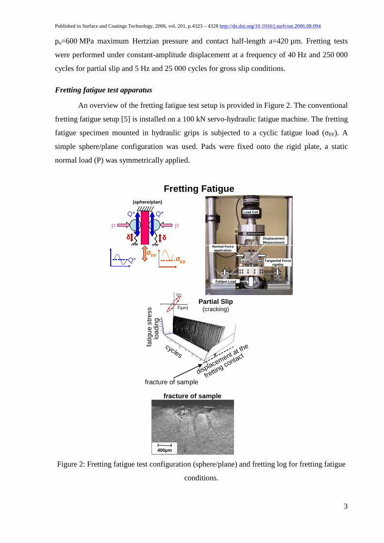
Fretting fatigue test apparatus
An overview of the fretting fatigue test setup is provided in Figure 2. The conventional
fretting fatigue setup [5] is installed on a 100 kN servo-hydraulic fatigue machine. The fretting
fatigue specimen mounted in hydraulic grips is subjected to a cyclic fatigue load (σFF). A
simple sphere/plane configuration was used. Pads were fixed onto the rigid plate, a static
normal load (P) was symmetrically applied.
Partial Slip(cracking)
Q*
δ (µm)
Fretting Fatigue(sphere/plan)
P
σσσσ
Q*
FF
δδδδ δδδδ
Q*σσσσFF
P
Q*
Normal Force application
Fatigue Load
Displacement Measurement
Load Cell
Tangential Force rigidity
cycles
fatig
ue s
tres
s lo
adin
g
fracture of sample
displacement at the
fretting contact
fracture of sample
400µm
Figure 2: Fretting fatigue test configuration (sphere/plane) and fretting log for fretting fatigue
conditions.

Published in Surface and Coatings Technology, 2006, vol. 201, p.4323 – 4328 http://dx.doi.org/10.1016/j.surfcoat.2006.08.094
4
The contact loading is associated with the relative displacement at the contact point between
the fatigue specimen and the fretting pad [6]. One original feature of the LTDS fretting fatigue
setup is the possibility of adjusting the fretting apparatus compliance in order to achieve and
maintain a given tangential fretting load (Q*). Relative displacement in the contact was
measured by a laser sensor installed on the fretting pad clamp and a reflecting mirror was
fixed on the flank of fatigue specimen at the contact position level. The fretting cycles (Q-δ),
were plotted along a time log, thus providing the so-called “fretting log” for fretting fatigue
conditions. During the test, fatigue loading (σFF), normal force (P), tangential force in the
contact (Q) and relative displacement (δ) were measured and recorded.
Material and surface treatments
The plain specimen and the associated substrates for surface treatments were made of
30NiCrMo steel. The plain specimens were machined to 10x10x15 mm rectangular prisms
with one face polished to an Ra < 0.05 µm average roughness. Similar roughness values were
measured on the 52100 AISI steel cylinder and sphere counter-body surface. The chemical
composition and mechanical properties of the studied material are the following: Chemical
composition, weight % (0.31% C; 1.06% Mn; 1.1% Cr; 0.79% Ni); Elastic modulus, E=200
GPa; Poisson ratio,ν =0.3; Yield stress, σY02=740 MPa; Maximum stress, σR=890 MPa;
Fatigue bending limit, σd(R=0)=400 MPa.
Shot peening treatments on the plain surfaces was conducted following the
conventional 0.0063A procedure (200% covering and balls of 0.6 mm diameter). Carried out
with the use of an air blast machine, it satisfies the MIL-S-13165 standard, equivalent to an
ALMEN intensity of 0.2-0.3 mm (from the AFNOR NFL 06832 standard). The average
measured roughness of the specimens was Ra=2 µm. The residual stress distribution was
measured by mean of XRD layer removal technique. The evolution of the compressive
residual stress field obtained on the treated surface is presented in Figure 3.

Published in Surface and Coatings Technology, 2006, vol. 201, p.4323 – 4328 http://dx.doi.org/10.1016/j.surfcoat.2006.08.094
5
-500
-400
-300
-200
-100
00 100 200 300 400 500
depth, µm
resi
dual
str
ess,
MP
a
fretting fatigue specimen
fretting wear specimen
Figure 3: Illustration of the measured residual stress fields after applying MIL-S-13165 shot
peening surface treatment.
A tungsten carbide thermal spray coating (HVOF WC-Co coating) was applied to
some part of the shot peened specimens. A WC-17%Co powder, with a mean particle size of
35 µm, was used for spraying from 228 mm distance. The DJ 2700 HVOF gun with flow of
O2-214 l/min, H2-684 l/min, N2-396 l/min and air 343 l/min was used to reach a 140 µm
coating thickness. Then the surface were polished to achieve an Ra=0.1 µm average surface
roughness.
Fretting test procedure and damage assessment
Before the tests the specimens were ultrasonically cleaned, first in acetone, and
secondly in ethanol. All the tests were carried out in ambient laboratory conditions, at room
temperature (~23ºC) and with a relative humidity between 40 and 50%. In order to quantify
the wear volume, the specimens were ultrasonically cleaned to eliminate as much debris as
possible. Several regularly-spaced surface profiles, perpendicular to the fretting scar, were
then made. An average fretting wear surface was then computed and, multiplied by the contact
length (L), which allowed the plane wear volume (PV ) to be estimated. A similar procedure to
measure the wear of the cylinder part (VC) was followed. The total wear volume of the tribo-
system was then calculated (VT=VP+VC). Hence, the total wear volume evolution versus the
accumulated dissipated energy during the fretting test could be plotted. More information
concerning the fretting wear energy methodology can be found in a previous work [4].

Published in Surface and Coatings Technology, 2006, vol. 201, p.4323 – 4328 http://dx.doi.org/10.1016/j.surfcoat.2006.08.094
6
Under fretting fatigue test conditions, in addition to contact fretting loading, the tested
material is subjected to homogenous bulk stress. The applied fretting fatigue investigation
methodology consists in identifying the threshold crack arrest conditions for the given fatigue
loading when the test overruns 107 cycles.
3. Results and discussion
Identification of sliding fretting regimes
The transition between partial slip and gross slip conditions [7] is quantified by
analysing the fretting cycle by the computing a non-dimensional energy sliding criterion
A=Ed/Et; where Ed is the dissipated energy of the corresponding cycle and Et=4·δ*·Q* is the
total energy [8].
As illustrated in Figure 4, there is no significant difference in the coefficient of friction
at the transition (µt≈0.81) between shot peening treatment and plain steel.
0.0
0.1
0.2
0.3
0.4
0.5
0.6
0.7
0.8
0.9
1.0
plain steel shot peening shot peening+ WC-Cocoating
coef
ficie
ntof
fric
tion
α cylinder (52100)
α plane (30NiCrMo)
0
0.5
1
1.5
2
2.5
3
ener
gy w
ear
coef
ficie
nt α
, (µ
m3 /
J)·1
04
µtµGS
Figure 4: Evolution of the coefficient of friction: - at the transition between partial slip and
gross slip µt, - in full sliding gross slip conditions µGS and quantification of the wear volume
based on a dissipated energy approach (cylinder/plane configuration).
After transition (PS/GS) the friction coefficient under gross slip conditions (µGS) decreases by
about 0.05. The thermal sprayed WC-Co coating displays slightly smaller transition, and gross
slip friction coefficients, than the metal/metal configuration (0.72-0.73). The representative

Published in Surface and Coatings Technology, 2006, vol. 201, p.4323 – 4328 http://dx.doi.org/10.1016/j.surfcoat.2006.08.094
7
fretting friction values (µt, µGS) defined for the studied contact couples are compiled in Table
I.
Table I: Fretting friction coefficient obtained for plain steel and studied surface treatments
(cylinder/plane configuration).
Surface treatment plain steel
/52100
shot peening
/52100
shot peening +
WC-Co coating
/52100
µt 0.81 0.83 0.73
µGS 0.76 0.77 0.72
Quantification of wear under fretting gross slip conditions
The wear of materials observed under gross slip conditions was studied using four
displacement amplitudes (±25, 50, 75 and 100 µm). Many authors quantify the wear rate using
Archard’s law [9]. The present study uses an energy approach [8], which displays higher
stability. This energy wear approach compares the wear volume to the accumulated dissipated
friction energy (∑Ed), or to the work of the tangential force. The observed, linear evolutions
allow the determination of energy wear coefficients:
dE
V
∆Σ∆=α , (µm3/J)
Figure 5 confirms the linear dependence; however this evolution does not cross the
origin of coordinates but presents a slight shift along the energy axis.

Published in Surface and Coatings Technology, 2006, vol. 201, p.4323 – 4328 http://dx.doi.org/10.1016/j.surfcoat.2006.08.094
8
0
4.5e+7
9.5e+7
1.5e+8
2.0e+8
2.5e+8
3.0e+8
0 5000 10000 15000
accumulated dissipated energy ΣEd, J
tota
l wea
r vo
lum
e, µ
m3
plain steel
shot peening + WC-Coshot peening
wear activation threshold energy
α total - energy wear coefficient
Figure 5: Energy wear coefficients obtained for the studied tribo-systems (cylinder/plane
configuration).
Previously associated with an incipient wear incubation threshold energy (Edth) [10], it has
been shown [10] that this energy can be related to the activation of a so-called Tribologically
Transformed Structure TTS [11]. All the studied tribo-systems display similar threshold
energies and can be directly analyzed by comparing the associated energy wear coefficients α
(Table II).
Table II: Results of fretting wear study under gross slip conditions and fretting fatigue limits
(sphere/plane configuration, 107 cycles, p0=600 MPa, a=840 µm, Q*=530 N).
Energy wear coefficients α, µm³/J Fretting
fatigue limit
Assessment
crack length
Surface treatments α plane α cylinder α total σFFmax lmax
µm³/J µm³/J µm³/J MPa µm
plain steel 14534 16372 30906 60 158
shot peening 18738 7936 26674 250 165
shot peening + WC-Co 920 2356 3276 260 0
It is observed that the shot peening treatment has a very little impact on wear
resistance. This confirms a previous study performed on TI-6Al-4V [12]. The plastic
deformation induced by shot peening is expected to increase the material’s hardness and

Published in Surface and Coatings Technology, 2006, vol. 201, p.4323 – 4328 http://dx.doi.org/10.1016/j.surfcoat.2006.08.094
9
potentially its wear resistance. However, this tendency is not observed, and even the reverse
can be shown (Figure 5). The contact strain loadings are so severe that they erase the previous
plastic strain history, and overshadow the shot peening impact. Deeper investigations are
required to explain this behaviour. Very good results are observed for the tungsten-carbide
cobalt (WC-Co) coating which increases the wear resistance by a factor of 9 (Figure 5).
Quantification of fretting cracking under partial slip regime
The cracking under stabilized partial slip conditions is analyzed by considering the two
following parameters which are: the crack nucleation threshold of the tangential force
amplitude (Qth*) and the maximum crack length defined at 90% of the maximum tangential
force amplitude associated to the sliding transition: )Q%90(l *tmax . The methodology
described in a previous work [4] has been applied to identify these parameters (Figure 6).
0
50
100
150
200
0 100 200 300 400 500
amplitude of tangential force Q*, N/mm
max
imum
cra
ck le
ngth
l max
, µm
plain steel
shot peening + WC-Coshot peening
Figure 6: Fretting wear cracking nucleation and propagation evolution of studied tribo-
systems under partial slip conditions (cylinder/plane configuration).
For the plain 30NiCrMo materials the crack nucleation threshold amplitude is
Qth*=218 N/mm, and the maximum observed crack length is lmax=155 µm. The cracking
evolution for shot peening treatment demonstrates no influence on the crack nucleation
threshold, but presents a good benefit in terms of crack propagation reduction. Indeed, the
intensive surface strain deformation tends to rapidly relax the initial compressive stresses
induced by the shot peening treatment. Hence the potential benefit of shot peening regarding

Published in Surface and Coatings Technology, 2006, vol. 201, p.4323 – 4328 http://dx.doi.org/10.1016/j.surfcoat.2006.08.094
10
crack nucleation is very limited. When the cracks propagate below the surface, higher
compressive stress states are maintained. The potential influence of shot peening on the crack
propagation rate reduction is then greater. However, this will require complex and specific
analyses which could not be performed in the framework of this research. Nevertheless a basic
qualitative comparison between the initial 300 µm depth compressive domain with the
maximum 155 µm crack length assessment tends to confirm the above conjecture.
Analysis of the WC-Co coating shows that no crack nucleation take place within the
studied loading conditions. The results suggest that such treatment appears to be a very
efficient fretting cracking palliative. However, the plain fretting cracking investigation which
is pertinent to record the contact’s impact on crack nucleation and initial crack propagation is
not sufficient to describe fully the global cracking behaviour. Combined fretting and bulk
fatigue loading has to be investigated to evaluate how an initial surface crack can propagate
until the specimen fails.
Quantification of fretting fatigue cracking under partial slip regime
One specific feature of the LTDS fretting fatigue apparatus is that it allows the
tangential force amplitude to be monitored, so an iso-fretting fretting fatigue endurance curve
can be obtained. However this setup system was not able, at that time, to adjust a
cylinder/plane configuration. A simple sphere/plane contact, giving an equal maximum
Hertzian pressure (p0=600 MPa) was used, with a 100 mm radius spherical surface shape, to
which a P=886 N normal force was applied. It provided a=840 µm contact radius. A pre-load
methodology was applied to adjust an alternating fretting loading (i.e. fretting loading ratio
RFretting=Q*min/Q*max=-1) and repeated fatigue stressing (i.e. fatigue stress ratio
RFatigue=σFFmin/σFFmax=0). A constant Q*=530 N tangential fretting force amplitude loading
was applied for all the fretting fatigue tests. The corresponding fretting fatigue endurance
curves are displayed in Figure 7 and the associated fretting fatigue limits are summarized in
Table II.

Published in Surface and Coatings Technology, 2006, vol. 201, p.4323 – 4328 http://dx.doi.org/10.1016/j.surfcoat.2006.08.094
11
0
50
100
150
200
250
300
350
400
450
1.E+04 1.E+05 1.E+06 1.E+07 1.E+08
fatig
ue s
tres
s am
plitu
de (
R=
0) σ
FF
a, M
Pa
number of cycles
fatigue limit
plain steelshot peening + WC-Coshot peening + WC-Co failure outside the contactshot peening
test overrun
Figure 7: Iso-fretting fretting fatigue endurance curve (p0=600 MPa, P=886 N, Q*=530 N,
RFretting=-1, RFatigue=0, σFFa=(σFFmax-σFFmin)/2=σFFmax/2).
A first comparison with plain fatigue limit clearly shows that the endurance reduction
is dramatic for the untreated steel, with a reduction factor of more than 85%. This tendency
has been observed in numerous previous investigations [5]. However, one interesting aspect
of this work is that the iso-fretting condition permits direct quantitative comparison of the
whole fatigue loading range and the surface treatments. Both the shot peening and combined
WC-Co coating treatments display a significantly better performance. The endurance
reduction at the fatigue limit is less than 35%. Note that for the highest fatigue loading ranges,
the failures on the shot peening+WC-Co specimen were observed outside the contact zone. It
infers that this treatment fully protects against fretting loading, but can reduce the plain fatigue
performance of the material. More precise investigation is, nevertheless, required to confirm
this.
Another question concerns the damage mechanism associated with the given fatigue
limits. The unbroken fretting fatigue specimens were examined at the fretting fatigue limit.
The corresponding crack lengths are reported in Table II. From this comparison it can be
concluded that the fretting fatigue limit corresponds to a crack nucleation threshold for the

Published in Surface and Coatings Technology, 2006, vol. 201, p.4323 – 4328 http://dx.doi.org/10.1016/j.surfcoat.2006.08.094
12
WC-Co coating, and to crack propagation arrest conditions for the referenced material and
shot peening treatment. Such results are fundamental. They clearly outline the difference
between the shot peening+WC-Co and the plain shot peening treatment. They also outline
that, depending on the material and surface treatments, predicting and modelling the fretting
fatigue endurance must take into account either a crack nucleation approach or a crack arrest
description. Hence, if they confirm that for plain steel and shot peening the crack arrest
approach is appropriate [13] they also demonstrate that for the WC-Co coating then a crack
nucleation formulation must be adopted. Hence the crack arrest is identified at about 160 µm,
which corresponds to a half compressive zone which plays an effective role in the crack arrest
condition and can explain the significant difference with the untreated steel.
4. Conclusions
This paper investigates a shot peening treatment and a WC-Co coating applied to
30NiCrMo steel against 52100 steel under plain fretting and complex fretting fatigue loading.
This analysis leads to the following conclusions: the studied tribo-systems present mainly
stable friction behaviour. Only WC-Co decreases the value of the coefficient of friction; shot
peening treatment has very little influence on fretting wear resistance under gross slip
conditions and has no influence on the crack nucleation threshold (Qth), but performs well
against crack propagation under plain fretting and the studied fretting fatigue conditions. The
fretting wear resistance of the WC-Co coating is very good under gross slip conditions and
decreases by more than 9 times the energy wear coefficient (α) as well as reducing the crack
nucleation under both fretting and fretting fatigue studied situations. Prediction of fretting
fatigue endurance is dependent on the surface treatment. A crack nucleation approach must be
considered for the WC-Co coating whereas a crack arrest formulation is required for the
uncoated systems.
5. References
[1] L. Vincent, Materials and fretting, Frett. Fatig. ESIS 18, 1994, p. 323-337.
[2] R. T. R. McGrann et all, The effect of coating residual stress on the fatigue life of
thermal spray-coated steel and aluminum, Surface and Coatings Technology, Vol. 108-
109, 1998, p. 59-64.

Published in Surface and Coatings Technology, 2006, vol. 201, p.4323 – 4328 http://dx.doi.org/10.1016/j.surfcoat.2006.08.094
13
[3] J. M. Miguel, J. M. Guilemany, B. G. Mellor and Y. M. Xu, Acoustic emission study
on WC-Co thermal sprayed coatings, Materials Science and Engineering A, Vol. 352,
2003, p. 55-63.
[4] K. Kubiak, S. Fouvry, A-M. Marechal, A practical methodology to select fretting
palliatives: application to shot peening, hard chromium and WC-Co coatings, Wear,
Vol. 259, 2005, p. 367-376.
[5] M. P. Szolwinski and T. N. Farris, Mechanics of fretting fatigue crack formation,
Wear, Vol. 198, Issues 1-2, 1996, p. 93-107.
[6] D. Nowell, D. Dini, D.A. Hills, Recent developments in the understanding of fretting
fatigue, Engineering Fracture Mechanics, Vol. 73, Issue 2, Advanced Fracture
Mechanics for Life Safety Assessments, 2006, p. 207-222.
[7] J.M. Voisin, A.B. Vannes, L. Vincent, J. Daviot, B. Giraud, Analysis of a tube-grid
oscillatory contact: methodology for the selection of superficial treatments, Wear, Vol.
181–183, 1995, p. 826–832.
[8] S. Fouvry, P. Kapsa, L. Vincent, Quantification of fretting damage, Wear, Vol. 200,
1996, p. 186–205.
[9] J. Archard, Contact and rubbing of flat surfaces, Appl. Phys., Vol. 24, 1953, p. 981–
988.
[10] S. Fouvry, T. Liskiewicz, Ph. Kapsa, S. Hannel, S. Sauger, An energy description of
wear mechanisms and its applications to oscillating sliding contacts, Wear, Vol. 255,
2003, p. 287–298.
[11] E. Sauger, S. Fouvry, L. Ponsonnet et al, Tribologically transformed structure in
fretting, Wear, Vol. 245, 2000, p. 39–52.
[12] V. Fridrici, S. Fouvry and Ph. Kapsa, Effect of shot peening on the fretting wear of Ti-
6Al-4V, Wear, Vol. 250, 2001, p. 642-649.
[13] J. A. Araújo and D. Nowell, Analysis of pad size effects in fretting fatigue using short
crack arrest methodologies, International Journal of Fatigue, Vol. 21, 1999, p. 947-
956.