behaviour of symmetric steel i-sections under combined bending and torsion actions …...
TRANSCRIPT

Behavior of symmetric steel I-sections under combined bending and torsion actions in inelastic range
A.R. Tusnin, M. Prokic

• In European codes and Russian standards for design of steel structures, calculation of members is performed taking into account development of plastic deformations.
• Bearing capacity check in the current Russian Code for design of steel structures is performed by formula
• Where - plastic shape coefficients (factors) for axial force and bending moment, which account development of plastic deformations in the cross section.
• The existing normative documents for the design of steel structures in Russia do not include coefficient taking into account the development of plastic deformations in warping torsion.
• Therefore, the purpose of the study was to determine this factor in warping torsion.
• Primarily, symmetric I-sections under the action of only bimoment were examined.
• Plastic shape coefficient in warping torsion is defined as the ratio of plastic bimoment
to elastic bimoment:
• Studies were carried out by Trahair N.S. and expressions of plastic bimoment for a number of profiles were obtained.
,min ,min ,min
1
n
yx
n y c x xn y c y yn y c n y c
MM BN
A R c W R c W R W R
, ,x yn c c
el
plBc
B
plB

• For symmetric I-beams the plastic bimoment can be determined by using simple method of analyzing bearing capacity at full development of plastic deformations.
Fig. 1. Deformations and sectorial stresses in a symmetric I-section under warping torsion
Fig. 2. Determination of plastic bimoment
• Plastic shape coefficient:
+
+
h
b
+
+
+
+
h
Mz
Mz
h
Af
Af
+
hbf /4
hbf /4
bf /4
bf /4
Sðàñ
Sñæ+
+
bf
, . , .pl ,
3 2
el ,el
4
/
24
f f
com tenpl
f f
A b hS SB W
ct b hB W I
1,5

• For monosymmetric I-section value of is defined analogously.
Fig. 3. Deformations and sectorial stresses in a monosymmetric I-section under warping torsion
• In case, when , at the loss of bearing capacity larger flange will be fully
elastic.
• Constant value should be taken somewhat less than the theoretical, because the
elastic core of section is preserved in the smaller flange. Based on this .
plB
h
b2
b1
2
2 2
2
1 1
2
3
b t
b t
1,47c

• Recommended formula for bearing capacity check of I-profiles in warping torsion, considering development of plastic deformations has the form:
where .
• These studies were extended to analyzing stress-strain state of a symmetric I-section under combined bending moment and bimoment actions in inelastic range.
Fig. 4. Stress-strain state of I-section under the combined action of bending moment about the X axis and bimoment
1 ,y c
B
c W R
1,47c
X
-
+
-+
+
-
+
-
-
+
y
tw
tfhw
tf
h
bf
a
y
y
y
y
-+
и

• These studies were extended to analyzing stress-strain state of a symmetric I-section under combined bending moment and bimoment actions in inelastic range.
Fig. 4. Stress-strain state of I-section under the combined action of bending moment about the X axis and bimoment
• Width “a” on normal stress diagram is easy to determine from equality of external and
internal bending moments: .
• The width “a” is equal: .
X
-
+
-+
+
-
+
-
-
+
y
tw
tfhw
tf
h
bf
a
y
y
y
y
-+
и
Bending moment and Bimoment
intM M
4
4
w y w
f y f y f
M A h AMa
t h t h t

• Bimoment resisted by the section is: , where .
• Substituting value “a” defined above in the formula for “c”, and equating external bimoment with internal we obtain:
(1)
• Analysis of expression (1) shown, that ultimate bimoment depends on the value of bending moment acting combined with bimoment.
• Calculations were performed, where relations of ultimate bimoment to plastic bimoment
are depending on the ratio of acting moment to a plastic moment .
Two schemes for determining required ratio were given:
• 1st scheme: from condition , so that
• 2nd scheme: bimoment is determined by expression (1), which is modified given the fact
that in RF norms development of plastic deformations in cross-section is limited. Therefore,
in the region of neutral axis the elastic core is preserved, and bimoment is defined by:
• where - moment resisted by wall with the development of plastic
deformations and .
int ( )f yB ct c a h ( ) / 2fc b a
0.54 2 2 8
w y f wf y
f y f
A b h A hM MB A
h t t
y c
n n
M BR
cW с W
/ /pl y c n pl
n
MB B R с W B
cW
/ plB B / plM M
0.52 2 2
wpl f wpl
f y
f y f y
M b h MM MB A R
h h t R t R
wpl pl f yM M A R h
wa t

Table 1 Calculation of the combined moment and bimoment actions
Section type 1 2 3 4 5
h w , cm 40.00 50.00 50.00 75.00 80.00
t w , cm 0.80 0.60 0.60 0.80 1.00
b f , cm 10.00 14.00 16.00 25.00 40.00
t f , cm 1.4 1.6 1.8 2.0 2.2
h, cm 41.4 51.6 51.8 77.0 82.2
Aw, cm2 32.0 30.0 30.0 60.0 80.0
Af, cm2 14.0 22.4 28.8 50.0 88.0
I t , cm4 30.1 50.2 79.0 175.4 372.7
I w , cm6 99981 487071 824291 7720052 39640128
W, cm3 760.0 1356.0 1674.9 4464.6 8056.1
W w , cm4 982.6 2739.4 4048.6 16252.7 48878.1
GI t , kN/m2 23.512 39.152 61.596 136.781 290.734
EI w , kN/m4 20.596 100.337 169.804 1590.331 8165.866
k 1.068 0.625 0.602 0.293 0.189
Ry, kN/cm2 24.0 24.0 24.0 24.0 24.0
Af/Aw 0.438 0.747 0.960 0.833 1.100
с 1.138 1.095 1.074 1.087 1.067
с w 1.470 1.470 1.470 1.470 1.470
Мpl, кN·m 207.48 356.48 431.74 1164.36 2063.01
Мwpl, кN·m 68.38 79.07 73.69 240.36 326.94
Вpl, кN·m2 3.47 9.66 14.28 57.34 172.44
В/Вpl at moment 0 1.000 1.000 1.000 1.000 1.000
В/Вpl at moment 0.2Мpl 0.800 0.800 0.800 0.800 0.800
В/Вpl at moment 0.4Мpl 0.600 0.600 0.600 0.600 0.600
В/Вpl at moment 0.6Мpl 0.400 0.400 0.400 0.400 0.400
В/Вpl at moment 0.8Мpl 0.200 0.200 0.200 0.200 0.200
В/Вpl at moment Мpl 0.000 0.000 0.000 0.000 0.000
В/Вpl at moment 0 1.000 1.000 1.000 1.000 1.000
В/Вpl at moment 0.2Мpl 1.000 1.004 1.001 1.000 1.004
В/Вpl at moment 0.4Мpl 0.992 0.952 0.926 0.947 0.924
В/Вpl at moment 0.6Мpl 0.840 0.767 0.734 0.759 0.730
В/Вpl at moment 0.8Мpl 0.509 0.450 0.425 0.444 0.422
В/Вpl at moment Мpl 0.000 0.000 0.000 0.000 0.000
Calculation of 1st scheme
Calculation of 2nd scheme

Fig.5. The variation of ratio with
• In the first scheme calculations, ratio varies linearly with. In the second scheme calculations relationship is non-linear, at the same time bimoment value is noticeably higher than in the first scheme.
• To assess the reliability of theoretical relationships, numerical studies of I-section profiles were performed in computing complex Nastran.
/ plB B / plM M
#ЗНАЧ! 1 1 2.2 0.7
0.8
0.9
1
0.000
0.100
0.200
0.300
0.400
0.500
0.600
0.700
0.800
0.900
1.000
0.00 0.20 0.40 0.60 0.80 1.00
B/Bp
l
M/Mpl
Scheme 1
Section 1
Section 2
Section 3
Section 4
Section 5
Numerical studies of I-section profiles in Nastran
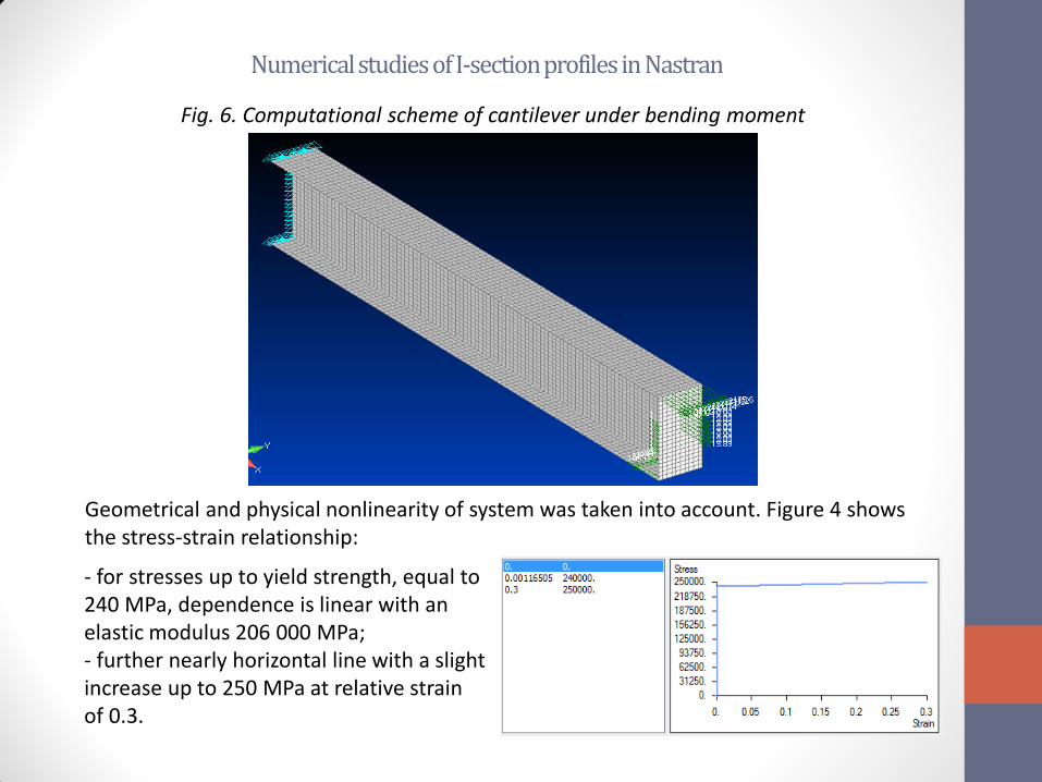
Fig. 6. Computational scheme of cantilever under bending moment
- for stresses up to yield strength, equal to 240 MPa, dependence is linear with an elastic modulus 206 000 MPa; - further nearly horizontal line with a slight increase up to 250 MPa at relative strain of 0.3.
Geometrical and physical nonlinearity of system was taken into account. Figure 4 shows the stress-strain relationship:

Fig. 5. The distribution of normal stresses over the section at and
• For each scheme of combined moment and bimoment actions, nonlinear analysis was carried out as long as rod kept its bearing capacity. In the first stage following combinations of moment and bimoment actions were included:
• 1 combination: 𝑀 = 0 and 𝐵 = 𝐵𝑝𝑙 ; • 2 combination: 𝑀 = 0,2𝑀𝑝𝑙 and 𝐵 = 0,8𝐵𝑝𝑙 ; • 3 combination: 𝑀 = 0,4𝑀𝑝𝑙 and 𝐵 = 0,6𝐵𝑝𝑙 ; • 4 combination: 𝑀 = 0,6𝑀𝑝𝑙 and 𝐵 = 0,4𝐵𝑝𝑙 ; • 5 combination: 𝑀 = 0,8𝑀𝑝𝑙 and 𝐵 = 0,2𝐵𝑝𝑙 ; • 6 combination: 𝑀 = 𝑀𝑝𝑙 and 𝐵 = 0 ;
0,6 plB B0,4 plM M

• Calculations shown that in 3, 4 and 5 combination, difference between the ultimate load (consisting of the bending moment acting jointly with bimoment) and applied load was reaching 14%. At the second stage bimoment value was adjusted so that bearing capacity was provided at full load for each of the combinations. Relations of internal forces, obtained by different methods, which ensured bearing capacity, are shown in Table 2.
Relations of internal forces which ensured bearing capacity
• Analysis of numerical results showed that the bearing capacity of I-section profile, taking into account the development of plastic deformations, is significantly less than the bearing capacity obtained, both theoretically (option 2), and using the procedure similar to normative (option 1).
• In view of this, for practical calculations normative procedure needs to be clarified. Studies found that in bearing capacity check, a coefficient 𝑐𝜔 needs to be changed so that over the entire range of M and B ultimate bearing capacity is preserved.
М/Mpl В/Вpl
1st option Table 2 2nd option Table 2 The numerical calculation
0 1.000 1.000 1.000
0.2 0.800 1.004 0.800
0.4 0.600 0.924 0.400
0.6 0.400 0.730 0.260
0.8 0.200 0.422 0.100
1 0.000 0.000 0.000

Conclusions
• Coefficient should be changed when changing the ratio of 𝑀 𝑀𝑝𝑙 .
Table 4
Recommended values of 𝑐𝜔
• Intermediate values of coefficient are determined by linear interpolation.
• Final check of symmetric I-section profile bearing capacity should be carried out according to formula:
• where the coefficient 𝑐 is determined by the current regulations, coefficient 𝑐𝜔 - by Table 4.
М/Mpl В/Вpl
0 1.470
0.2 1.470
0.4 1.176
0.6 0.956
0.8 0.833
0.9 0.588
1 0.588
1n y c n y c
M B
cW R с W R
