behaviour of unconfined and frp-confined rubberised
TRANSCRIPT

Construction and Building Materials 147 (2017) 388–397
Contents lists available at ScienceDirect
Construction and Building Materials
journal homepage: www.elsevier .com/locate /conbui ldmat
Behaviour of unconfined and FRP-confined rubberised concrete in axialcompression
http://dx.doi.org/10.1016/j.conbuildmat.2017.04.1750950-0618/� 2017 The Authors. Published by Elsevier Ltd.This is an open access article under the CC BY-NC-ND license (http://creativecommons.org/licenses/by-nc-nd/4.0/).
⇑ Corresponding author.E-mail address: [email protected] (S. Raffoul).
Samar Raffoul ⇑, Reyes Garcia, David Escolano-Margarit, Maurizio Guadagnini, Iman Hajirasouliha,Kypros PilakoutasDept. of Civil and Structural Engineering, The University of Sheffield, Sir Frederick Mappin Building, Mappin Street, Sheffield S1 3JD, UK
h i g h l i g h t s
� Stress-strain behaviour of concrete with high percentage of rubber is examined experimentally.� External FRP confinement is used to enhance mechanical properties of rubberised concrete (RuC).� RuC early micro-cracking and lateral expansion is exploited to improve confinement effectiveness.� Confinement improves RuC compressive strength by 10 times and yields ultimate axial strains of 5%.� CRuC is suitable for structural applications with high strength and deformability requirements.
a r t i c l e i n f o
Article history:Received 12 October 2016Received in revised form 21 April 2017Accepted 23 April 2017
Keywords:Tyre rubberRubberised concreteFRP confinementHighly-deformable concrete
a b s t r a c t
This article investigates the use of externally bonded Fibre Reinforced Polymer (FRP) jackets to develop anovel high-strength, highly-deformable FRP Confined Rubberised Concrete (CRuC). Sixty rubberised con-crete (RuC) cylinders were tested in axial compression. The cylinders were produced using recycled tyrerubber to replace i) 0–100% fine or coarse aggregate volume or ii) a replacement of 40% or 60% of the totalaggregate volume. Six cylinders of the latter mix were then confined with either two or three layers ofAramid FRP sheets. The results indicate that the use of high rubber contents in concrete lead to prematuremicrocracking and lateral expansion, the latter of which can be used to activate the FRP confinement ear-lier and achieve higher confinement effectiveness. The CRuC cylinders reached compressive strengths ofup to 75 MPa and unprecedented ultimate axial strains up to 5%, i.e. about fourteen times larger thanthose of normal concrete (0.35%). Such novel high-strength, highly-deformable CRuC is of great valueto engineers and can be used for structural applications where large deformability is required.� 2017 The Authors. Published by Elsevier Ltd. This is anopenaccess article under the CCBY-NC-ND license
(http://creativecommons.org/licenses/by-nc-nd/4.0/).
1. Introduction
Worldwide tyre production is forecast to exceed 2.9 billionunits per year by the end of 2017 [1] and it is estimated that forevery tyre placed in the market, another tyre reaches its service lifeand becomes waste [2]. Over 300 million tyres reach their servicelife every year in the EU alone. Whilst stringent EU directives con-trol waste tyre disposal [3], waste tyres are still landfilled and cancause major public health risks and environmental issues. This hasincreased the efforts towards generating innovative applicationsfor scrap tyres and their main components (vulcanised rubber,steel wire and textile fibres) in the construction industry [4–6].
Vulcanised rubber used in tyre manufacturing has goodstrength and flexibility and an ability to maintain its volume undercompressive stress. Over the last few years, extensive research hasinvestigated the use of recycled tyre rubber as mineral aggregatereplacement in concrete. The results from these studies indicatethat, compared to normal concrete, rubberised concrete (RuC)has higher deformation capacity [7,8] and vibration damping [9–11]. Conversely, RuC has lower compressive strength, tensilestrength and stiffness [12–16]. The compressive strength of RuCwith high rubber contents (replacement volumes >50–60%) canbe up to 90% lower than that of normal concrete [12,13,17,18].Such low strength can be mainly attributed to the a) low stiffnessand high Poisson’s ratio of rubber, resulting in stress concentra-tions within the mix, b) hydrophobic nature of rubber, whichcauses weak rubber-cement matrix bonding, c) increased mixnon-homogeneity, d) increased porosity and air content, and e)lower ‘‘mass stiffness” of RuC [14–16]. The inclusion of rubber in

0-5mm
m
S. Raffoul et al. / Construction and Building Materials 147 (2017) 388–397 389
concrete also affects its mix fresh properties, leading to high segre-gation and bleeding, high air content, as well as low slump andworkability [17,19–21]. Whilst considerable amount of literaturehas been published on RuC, there is a general lack of consensuson the influence of rubber on the physical and mechanical proper-ties of fresh and hardened concrete. Due to the insufficient under-standing of the influence of rubber on the mechanical properties ofconcrete, to date RuC is mainly used in low-strength, non-structural applications such as concrete pedestrian blocks, trafficbarriers or lightweight fills [18,21–23].
More recently, limited research has examined the use of FibreReinforced Polymer (FRP) sheets to confine RuC specimens (con-taining low rubber contents) in an attempt to develop adequateaxial strength and exploit the potential deformation capacity thatRuC can offer [24–28]. Li et al. [25] tested confined rubberised con-crete (CRuC) cylinders cast in prefabricated Glass FRP (GFRP) pipes.Whilst the GFRP CRuC specimens were up to 5.25 times strongerthan the equivalent unconfined RuC specimens, relatively lowcompressive strengths of 16.3–22.9 MPa were achieved. Moreover,maximum axial strain values of only about 2.5% could be devel-oped, which are similar to what can be achieved with GFRP con-fined cylinders made of conventional concrete [29]. Youssf et al.[24] tested CRuC cylinders cast in preformed Carbon FRP (CFRP)tubes. The compressive strength of these cylinders ranged from61.7 MPa (for one CFRP layer) to 112.5 MPa (for three CFRP layers),thus being suitable for structural applications. However, thedeformability potential from using rubber particles was not fullyexploited, since the stress-strain behaviour of the CFRP CRuC cylin-ders [24] was similar to that of CFRP-confined cylinders with con-ventional concrete [29]. More recently, Duarte et al. [27] testedshort RuC columns confined with cold formed steel tubes. Whilstthe column ductility was increased by up to 50%, the capacity ofthe specimens was limited by the premature local buckling ofthe steel tubes. It should be noted that the studies discussed aboveonly made use of low rubber contents, replacing about 30% of thefine aggregates [25], or 10% [24] and 15% [27] of the total aggre-gates, and provide evidence that the use of small volumes of rubberaggregate replacement has a minor effect on concrete deformabil-ity. The use of higher rubber contents has been previously associ-ated with several material and technological issues and, onlyrecently, work by the authors [30] has successfully addressed someof these challenges and enabled the development of a modifiedconcrete with high rubber contents (>50%) suitable for the manu-facture of highly deformable CRuC (axial strains >5%) elementsfor structural applications.
This article summarises the methodology implemented for thedevelopment of improved rubber modified concrete mixes andinvestigates experimentally the use of externally bonded FRP con-finement to exploit the deformation capacity of RuC and develophigh-strength, highly-deformable FRP CRuC elements. The resultspresented in this article are part of the ongoing EU-funded projectAnagennisi, which investigates the innovative reuse of all tyrecomponents in concrete [31]. This work is expected to contributetowards the understanding of the mechanical behaviour of FRPCRuC and towards the development of a highly-deformable con-crete for high-value structural applications.
5-10m
10-20mm
Fig. 1. Rubber particles used to replace sand (size: 0–5 mm) and gravel (sizes: 5–10 mm and 10–20 mm).
2. Experimental programme
The mechanical performance of RuC (with and without FRP con-finement) was investigated experimentally using a total of 66cylinders (100 � 200 mm) cast from 15 different mixes. The mainparameters investigated were the effect of rubber content, rubbertype and the number of FRP layers on the stress-strain behaviourof RuC up to peak stress.
2.1. Materials
2.1.1. Concrete and rubberAll mixes were produced using CEM II-52.5 N Portland Lime-
stone Cement, containing around 10–15% Limestone in compliancewith BS EN 197-1 [32]. Two types of commercial high-range waterreducing admixtures [33,34] were used. The fine aggregates weremedium grade river washed sand from Shardlow, Derbyshire(UK) with size: 0–5 mm, specific gravity: 2.65, water absorption:0.5%, and fineness modulus: 2.64. The coarse aggregates wereround river washed gravel from Trent Valley (UK) with sizes: 5–10 and 10–20 mm, specific gravity: 2.65, and water absorption:1.24%.
To examine the influence of rubber type and content on thestress-strain behaviour of RuC, rubber particles were used toreplace either a) fine aggregates (sand) by 0–100% by volume, b)coarse aggregates (gravel) by 0–100% by volume, or c) both fineand coarse aggregates by 40% and 60% by volume. The rubber par-ticles were obtained from mechanical shredding of vehicular tyresand had a rough, jagged surface with traces of contamination fromsteel and polymer fibres. The rubber particles (shown in Fig. 1)were classified as follows: a) fine rubber particles (size 0–5 mm)used as sand replacement, and b) coarse rubber particles (sizes5–10 mm and 10–20 mm) used as gravel replacement. Fig. 2 showsthe particle size distribution of the rubber aggregates determinedaccording to ASTM C136 [35]. Table 1 summarises the physicalproperties of rubber and mineral aggregates. The rubber particledensity and water absorption, flakiness index and bulk densitywere obtained following Annex C of BS EN 1097-6 (lightweightaggregates) [36], BS EN 933-3 [37] and BS EN 1097-3 [38], respec-tively. It should be noted, however, that these tests could not beperformed on the fine rubber particles (size 0–5 mm) as these floatin water and agglomerate due to surface tension and inter-particular forces.
2.1.1.1. Mix design. Previous research by the authors [30] indicatedthat the inclusion of large volumes of rubber in concrete could leadto very unstable mixes with high levels of segregation and a lack ofcohesion, accompanied with significant compressive strengthreductions. To minimise such adverse effects, the authors investi-gated the various mix parameters that influence RuC and proposedan ‘optimised’ mix design [30] that results in a concrete with goodfresh properties (homogeneity and cohesion) and enhanced com-pressive strength. For instance, when compared to a non-optimised mix with 100% fine rubber replacing sand, the ‘opti-mised’ mix was 2.6 times stronger (average strengths of 3.7 and
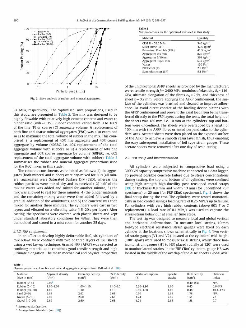
Fig. 2. Sieve analysis of rubber and mineral aggregates.
Table 2Mix proportions for the optimised mix used in this study.
Material Quantity
CEM II – 52.5 MPa 340 kg/m3
Silica Fume (SF) 42.5 kg/m3
Pulverised Fuel Ash (PFA) 42.5 kg/m3
Aggregates 0/5 mm 820 kg/m3
Aggregates 5/10 mm 364 kg/m3
Aggregates 10/20 mm 637 kg/m3
Water 150 l/m3
Plasticiser (P) 2.5 l/m3
Superplasticiser (SP) 5.1 l/m3
390 S. Raffoul et al. / Construction and Building Materials 147 (2017) 388–397
9.6 MPa, respectively). The ‘optimised’ mix proportions, used inthis study, are presented in Table 2. The mix was designed to behighly flowable with relatively high cement content and water tobinder ratio (w/b = 0.35). Rubber contents varied from 0 to 100%of the fine (F) or coarse (C) aggregate volume. A replacement ofboth fine and coarse mineral aggregates (F&C) was also examinedso as to maximise the total volume of rubber in the mix. This com-prised: i) a replacement of 40% fine aggregate and 40% coarseaggregate by volume (40F&C, i.e. 40% replacement of the totalaggregate volume with rubber), or ii) a replacement of 60% fineaggregate and 60% coarse aggregate by volume (60F&C, i.e. 60%replacement of the total aggregate volume with rubber). Table 3summarises the rubber and mineral aggregate proportions usedfor the RuC mixes in this study.
The concrete constituents were mixed as follows: 1) the aggre-gates (both mineral and rubber) were dry-mixed for 30 s (all min-eral aggregates were Saturated Surface Dry (SSD), whereas therubber particles were mixed dry and as-received), 2) half of themixing water was added and mixed for another minute, 3) themix was allowed to rest for three minutes, 4) the binder materialsand the remaining mixing water were then added followed by agradual addition of the admixtures, and 5) the concrete was thenmixed for another three minutes. The cylinders were cast in twolayers and vibrated on a vibrating table (15–20 s per layer). Aftercasting, the specimens were covered with plastic sheets and keptunder standard laboratory conditions for 48hrs. They were thendemoulded and stored in a mist room for another 25 days.
2.1.2. FRP confinementIn an effort to develop highly deformable RuC, six cylinders of
mix 60F&C were confined with two or three layers of FRP sheetsusing a wet lay-up technique. Aramid FRP (AFRP) was selected asconfining material as it combines good tensile strength and highultimate elongation. The mean mechanical and physical properties
Table 1Physical properties of rubber and mineral aggregates (adapted from Raffoul et al. [30]).
Material(size in mm)
Apparent density(t/m3)
Oven dry density(t/m3)
SSDa densit(t/m3)
Rubber (0–5) 0.80b – –Rubber (5–10) 1.10–1.20 1.00–1.10 1.10–1.2Rubber (10–20) 1.10 1.10 1.10Sand (0–5) 2.65 2.62 2.63Gravel (5–10) 2.69 2.60 2.63Gravel (10–20) 2.69 2.60 2.63
a Saturated Surface Dry.b Average from literature (see [30]).
of the unidirectional AFRP sheets, as provided by the manufacturer,were: tensile strength ff = 2400 MPa, modulus of elasticity Ef = 116-GPa, ultimate elongation of the fibres efu = 2.5%, and thickness ofsheet tf = 0.2 mm. Before applying the AFRP confinement, the sur-face of the cylinders was brushed and cleaned to improve adher-ence. To avoid direct contact of the loading device platens withthe AFRP confinement and prevent the axial load from being trans-ferred directly to the FRP layers during the tests, the total height ofthe sheets was 180 mm, i.e. 10 mm at the cylinders’ top and bot-tom were unconfined. The sheets were overlapped by a length of100 mm with the AFRP fibres oriented perpendicular to the cylin-ders’ axes. Acetate sheets were then placed on the exposed surfaceof the AFRP to achieve a smooth resin layer finish, thus enablingthe easy subsequent installation of foil-type strain gauges. Theseacetate sheets were removed after one day of resin curing.
2.2. Test setup and instrumentation
All cylinders were subjected to compressive load using a3000 kN capacity compressive machine connected to a data logger.To prevent possible concrete failure due to stress concentrationsduring testing, the top and bottom of all cylinders were confinedusing high-strength high-ductility post tensioned metal straps[39] of thickness 0.8 mm and width 13 mm (for unconfined RuCspecimens) or 25 mm (for FRP CRuC specimens). Fig. 3 shows thefinal setup during the test. The cylinders were tested monotoni-cally in load control using a loading rate of 0.25 MPa/s up to failure.For cylinders with very high rubber contents (above 60% F or Creplacement), a load rate of 0.1 MPa/s was used to capture thestress-strain behaviour at smaller time steps.
The test rig was designed to measure local and global verticaland horizontal deformations. To measure local strains, 10 mmfoil-type electrical resistance strain gauges were fixed on eachcylinder at the locations shown schematically in Fig. 4. Two verti-cal strain gauges (V1 and V2), located at the cylinders’ mid-height(180� apart) were used to measure axial strains, whilst three hor-izontal strain gauges (H1 to H3) placed radially at 120� were usedto monitor lateral strains. In the FRP CRuC cylinders, gauge H3 waslocated in the middle of the overlap of the AFRP sheets. Global axial
y Water absorption(%)
Specificgravity
Bulk density(t/m3)
FlakinessIndex
– – 0.40–0.46 N/A5.30–8.90 1.10 0.45 6.6–8.30.80–1.30 1.10 0.48 10.4–17.50.50 2.65 1.78 N/A1.24 2.65 1.51 7.11.24 2.65 1.58 9.7
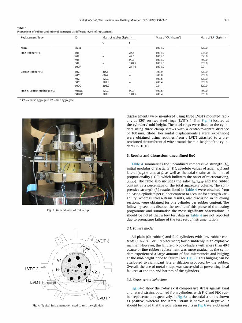
Table 3Proportions of rubber and mineral aggregate at different levels of replacement.
Replacement Type ID Mass of rubber (kg/m3) Mass of CAa (kg/m3) Mass of FAa (kg/m3)
C F
None Plain – – 1001.0 820.0
Fine Rubber (F) 10F – 24.8 1001.0 738.020F – 49.5 1001.0 656.040F – 99.0 1001.0 492.060F – 148.5 1001.0 328.0100F – 247.6 1001.0 0.0
Coarse Rubber (C) 10C 30.2 – 900.9 820.020C 60.4 – 800.8 820.040C 120.9 – 600.6 820.060C 181.3 – 400.4 820.0100C 302.2 – 0.0 820.0
Fine & Coarse Rubber (F&C) 40F&C 120.9 99.0 600.6 492.060F&C 181.3 148.5 400.4 328.0
a CA = coarse aggregate, FA = fine aggregate.
Fig. 3. General view of test setup.
Fig. 4. Typical instrumentation used to test the cylinders.
S. Raffoul et al. / Construction and Building Materials 147 (2017) 388–397 391
displacements were monitored using three LVDTs mounted radi-ally at 120� on two steel rings (LVDTs 1–3 in Fig. 4) located atthe cylinders’ mid-height. The steel rings were fixed to the cylin-ders using three clamp screws with a centre-to-centre distanceof 100 mm. Global horizontal displacements (lateral expansion)were obtained using readings from a LVDT attached to a pre-tensioned circumferential wire around the mid-height of the cylin-ders (LVDT H).
3. Results and discussion: unconfined RuC
Table 4 summarises the unconfined compressive strength (fc),initial modulus of elasticity (Ec), absolute values of axial (ecp) andlateral (eclp) strains at fc, as well as the axial strains at the limit ofproportionality (LOP), which indicates the onset of microcracking,(ecLOP). The table also includes the ratio ecp/ecLOP and the rubbercontent as a percentage of the total aggregate volume. The com-pressive strength (fc) results listed in Table 4 were obtained fromat least 4 cylinders per rubber content to account for strength vari-ability, whereas stress-strain results, also discussed in followingsections, were obtained for one cylinder per rubber content. Thefollowing sections discuss the results of this phase of the testingprogramme and summarise the most significant observations. Itshould be noted that a few test data in Table 4 are not reporteddue to premature failure of the test setup/instrumentation.
3.1. Failure modes
All plain (0% rubber) and RuC cylinders with low rubber con-tents (10–20% F or C replacement) failed suddenly in an explosivemanner. However, the failure of RuC cylinders with more than 40%coarse or fine rubber replacement was more gradual as the cylin-ders experienced a large amount of fine microcracks and bulgingat the mid-height prior to failure (see Fig. 5). This bulging can beattributed to significant lateral dilation produced by the rubber.Overall, the use of metal straps was successful at preventing localfailures at the top and bottom of the cylinders.
3.2. Stress-strain behaviour
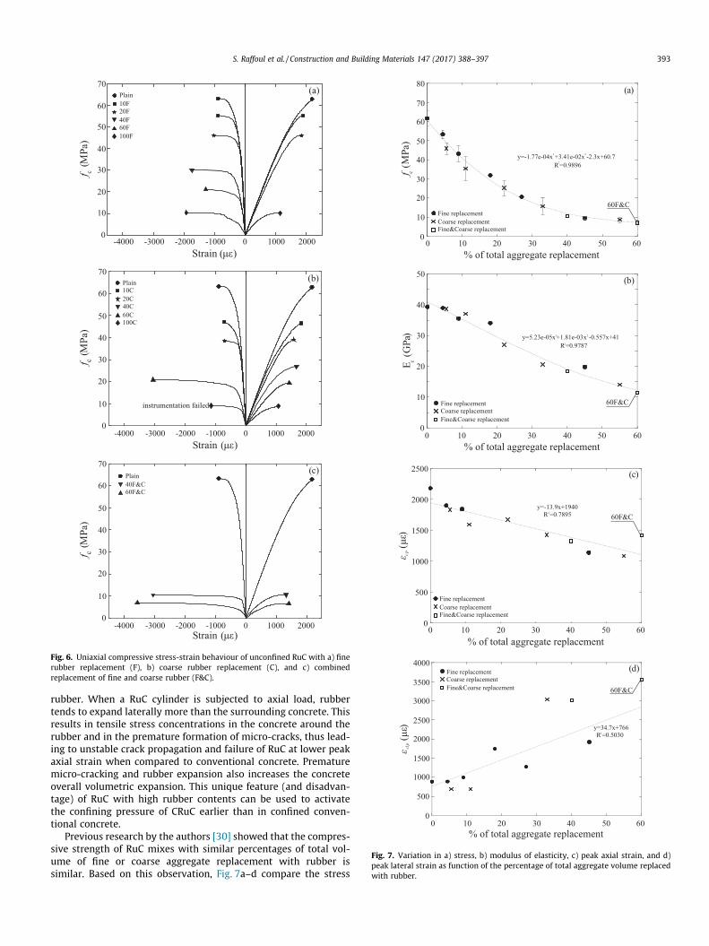
Fig. 6a-c show the 7-day axial compressive stress against axialand lateral strains obtained from cylinders with F, C and F&C rub-ber replacement, respectively. In Fig. 6a-c, the axial strain is shownas positive, whereas the lateral strain is shown as negative. Itshould be noted that the axial strain results in Fig. 6 were obtained
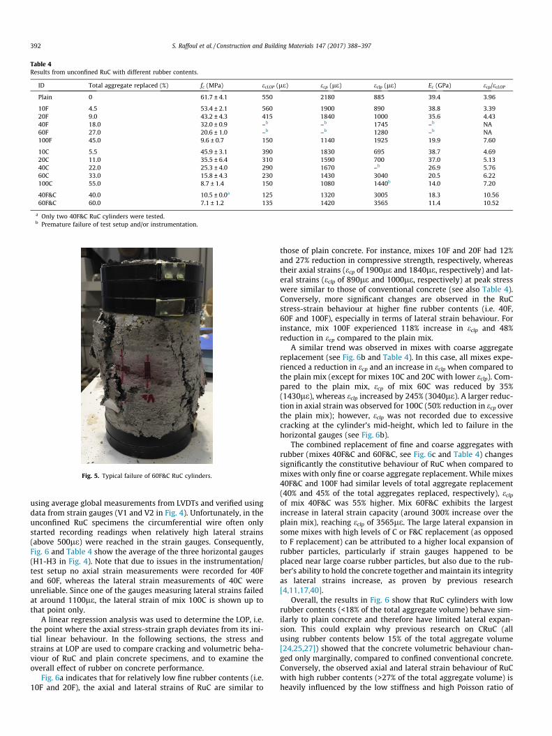
Table 4Results from unconfined RuC with different rubber contents.
ID Total aggregate replaced (%) fc (MPa) ecLOP (le) ecp (le) eclp (le) Ec (GPa) ecp/ecLOP
Plain 0 61.7 ± 4.1 550 2180 885 39.4 3.96
10F 4.5 53.4 ± 2.1 560 1900 890 38.8 3.3920F 9.0 43.2 ± 4.3 415 1840 1000 35.6 4.4340F 18.0 32.0 ± 0.9 –b –b 1745 –b NA60F 27.0 20.6 ± 1.0 –b –b 1280 –b NA100F 45.0 9.6 ± 0.7 150 1140 1925 19.9 7.60
10C 5.5 45.9 ± 3.1 390 1830 695 38.7 4.6920C 11.0 35.5 ± 6.4 310 1590 700 37.0 5.1340C 22.0 25.3 ± 4.0 290 1670 –b 26.9 5.7660C 33.0 15.8 ± 4.3 230 1430 3040 20.5 6.22100C 55.0 8.7 ± 1.4 150 1080 1440b 14.0 7.20
40F&C 40.0 10.5 ± 0.0a 125 1320 3005 18.3 10.5660F&C 60.0 7.1 ± 1.2 135 1420 3565 11.4 10.52
a Only two 40F&C RuC cylinders were tested.b Premature failure of test setup and/or instrumentation.
Fig. 5. Typical failure of 60F&C RuC cylinders.
392 S. Raffoul et al. / Construction and Building Materials 147 (2017) 388–397
using average global measurements from LVDTs and verified usingdata from strain gauges (V1 and V2 in Fig. 4). Unfortunately, in theunconfined RuC specimens the circumferential wire often onlystarted recording readings when relatively high lateral strains(above 500le) were reached in the strain gauges. Consequently,Fig. 6 and Table 4 show the average of the three horizontal gauges(H1-H3 in Fig. 4). Note that due to issues in the instrumentation/test setup no axial strain measurements were recorded for 40Fand 60F, whereas the lateral strain measurements of 40C wereunreliable. Since one of the gauges measuring lateral strains failedat around 1100le, the lateral strain of mix 100C is shown up tothat point only.
A linear regression analysis was used to determine the LOP, i.e.the point where the axial stress-strain graph deviates from its ini-tial linear behaviour. In the following sections, the stress andstrains at LOP are used to compare cracking and volumetric beha-viour of RuC and plain concrete specimens, and to examine theoverall effect of rubber on concrete performance.
Fig. 6a indicates that for relatively low fine rubber contents (i.e.10F and 20F), the axial and lateral strains of RuC are similar to
those of plain concrete. For instance, mixes 10F and 20F had 12%and 27% reduction in compressive strength, respectively, whereastheir axial strains (ecp of 1900le and 1840le, respectively) and lat-eral strains (eclp of 890le and 1000le, respectively) at peak stresswere similar to those of conventional concrete (see also Table 4).Conversely, more significant changes are observed in the RuCstress-strain behaviour at higher fine rubber contents (i.e. 40F,60F and 100F), especially in terms of lateral strain behaviour. Forinstance, mix 100F experienced 118% increase in eclp and 48%reduction in ecp compared to the plain mix.
A similar trend was observed in mixes with coarse aggregatereplacement (see Fig. 6b and Table 4). In this case, all mixes expe-rienced a reduction in ecp and an increase in eclp when compared tothe plain mix (except for mixes 10C and 20C with lower eclp). Com-pared to the plain mix, ecp of mix 60C was reduced by 35%(1430le), whereas eclp increased by 245% (3040le). A larger reduc-tion in axial strain was observed for 100C (50% reduction in ecp overthe plain mix); however, eclp was not recorded due to excessivecracking at the cylinder’s mid-height, which led to failure in thehorizontal gauges (see Fig. 6b).
The combined replacement of fine and coarse aggregates withrubber (mixes 40F&C and 60F&C, see Fig. 6c and Table 4) changessignificantly the constitutive behaviour of RuC when compared tomixes with only fine or coarse aggregate replacement. While mixes40F&C and 100F had similar levels of total aggregate replacement(40% and 45% of the total aggregates replaced, respectively), eclpof mix 40F&C was 55% higher. Mix 60F&C exhibits the largestincrease in lateral strain capacity (around 300% increase over theplain mix), reaching eclp of 3565le. The large lateral expansion insome mixes with high levels of C or F&C replacement (as opposedto F replacement) can be attributed to a higher local expansion ofrubber particles, particularly if strain gauges happened to beplaced near large coarse rubber particles, but also due to the rub-ber’s ability to hold the concrete together andmaintain its integrityas lateral strains increase, as proven by previous research[4,11,17,40].
Overall, the results in Fig. 6 show that RuC cylinders with lowrubber contents (<18% of the total aggregate volume) behave sim-ilarly to plain concrete and therefore have limited lateral expan-sion. This could explain why previous research on CRuC (allusing rubber contents below 15% of the total aggregate volume[24,25,27]) showed that the concrete volumetric behaviour chan-ged only marginally, compared to confined conventional concrete.Conversely, the observed axial and lateral strain behaviour of RuCwith high rubber contents (>27% of the total aggregate volume) isheavily influenced by the low stiffness and high Poisson ratio of
-4000 -3000 -2000 -1000 0 1000 2000
f c(M
Pa)
0
(a)
10
20
30
40
50
60
70
60F100F
40F20F10FPlain
Strain ( )με
S ( )train με-4000 -3000 -2000 -1000 0 1000 2000
f c(M
Pa)
0
10
20
30
40
50
60
70
60C100C
40C20C10CPlain
instrumentation failed
(b)
60F&C40F&CPlain
S ( )train με-4000 -3000 -2000 -1000 0 1000 2000
f c(M
P a)
0
10
20
30
40
50
60
70(c)
Fig. 6. Uniaxial compressive stress-strain behaviour of unconfined RuC with a) finerubber replacement (F), b) coarse rubber replacement (C), and c) combinedreplacement of fine and coarse rubber (F&C).
0 10 20 30 40 50 60
E c(G
Pa)
0
10
20
30
40
50
Fine replacementCoarse replacementFine&Coarse replacement
% of total aggregate replacement
60F&C
R2=0.9787y=5.23e-05x +1.81e-033 x -0.557x+412
(b)
0 10 20 30 40 50 600
500
1000
1500
2000
2500
ε cp(
)με
Fine replacementCoarse replacementFine&Coarse replacement
% of total aggregate replacement
60F&C=0.7895R2
y=-13.9x+1940
(c)
R2=0.5030
0
500
1000
1500
2000
2500
3000
3500
4000
ε c lp(
)μ ε
Fine replacementCoarse replacementFine&Coarse replacement 60F&C
0 10 20 30 40 50 60% of total aggregate replacement
y=34.7x+766
(d)
% of total aggregate replacement0 10 20 30 40 50 60
f c(M
P a)
0
10
20
30
40
50
60
70
80
Fine replacementCoarse replacementFine&Coarse replacement
(a)
60F&C
R2=0.9896y=-1.77e-04x +3.41e-02x -2.3x+60.73 2
Fig. 7. Variation in a) stress, b) modulus of elasticity, c) peak axial strain, and d)peak lateral strain as function of the percentage of total aggregate volume replacedwith rubber.
S. Raffoul et al. / Construction and Building Materials 147 (2017) 388–397 393
rubber. When a RuC cylinder is subjected to axial load, rubbertends to expand laterally more than the surrounding concrete. Thisresults in tensile stress concentrations in the concrete around therubber and in the premature formation of micro-cracks, thus lead-ing to unstable crack propagation and failure of RuC at lower peakaxial strain when compared to conventional concrete. Prematuremicro-cracking and rubber expansion also increases the concreteoverall volumetric expansion. This unique feature (and disadvan-tage) of RuC with high rubber contents can be used to activatethe confining pressure of CRuC earlier than in confined conven-tional concrete.
Previous research by the authors [30] showed that the compres-sive strength of RuC mixes with similar percentages of total vol-ume of fine or coarse aggregate replacement with rubber issimilar. Based on this observation, Fig. 7a–d compare the stress

Fig. 8. Typical failure modes of AFRP CRuC cylinders.
394 S. Raffoul et al. / Construction and Building Materials 147 (2017) 388–397
(fc), modulus of elasticity (Ec), axial strain (ecp), and lateral strain(eclp) at peak stress, respectively, as a function of the total aggre-gate volume replaced with rubber. As expected, the results inFig. 7a confirm that regardless of the type of rubber replacement(C, F or F&C), the strength of RuC mixes reduces with increasingrubber content (up to 90% for mix 60F&C with the highest totalaggregate replacement). However, the rate at which the com-pressive strength reduces is faster at lower rubber contentsand seems to stabilise at total rubber contents above 40%, whererubber properties appear to dominate the compressive behaviourof RuC.
Fig. 7b shows that Ec also reduces with increasing rubber con-tent. Such reduction in stiffness can be attributed to the lower stiff-ness of rubber particles (compared to mineral aggregates) and tothe higher air content, as confirmed by previous research [40].However, Ec seems to be minimally affected by the type of rubberreplacement (fine or coarse).
The data in Fig. 7c and Table 4 indicate that the axial strain atpeak stress (ecp) reduces with increasing rubber content. For mixeswith high rubber contents (e.g. mix 100C), ecp was only 50% of thecorresponding value for plain concrete (1080le vs 2180le, seeTable 4). This reduction in ecp was also accompanied by a reductionin axial strains at LOP (ecLOP). For instance, ecLOP reduced from550le in the plain mix to 150le for mixes 100F and 100C, andto 135le for mix 60F&C, respectively (see Table 4). This indicatesthat the onset of localised micro-cracking occurs at earlier stageswhen large volumes of rubber are added to concrete, thus leadingto premature lateral expansion. Whilst both ecp and ecLOP reducedwith increasing rubber contents, ecLOP reduced at a faster rate asevidenced by a consistently increasing ecp/ecLOP ratio (see Table 4)with increasing rubber contents (e.g. 4.69 and 10.52 for 10C and60F&C, respectively).
Although the data obtained from lateral strain gauges may havebeen affected by high heterogeneity of RuC and local phenomena(such as the high local expansion of large rubber particles), theresults in Fig. 7d and Table 4 show clearly that the lateral expan-sion eclp of RuC increases with the rubber contents, reaching valuesof more than 3500le for mix 60F&C (i.e. 4 times the eclp of the plainmix).
Based on the above discussion, it is evident that the inclusionof high rubber contents in concrete leads to larger lateral expan-sion and premature unstable crack propagation, which result inlow compressive strengths, stiffness and peak axial strains. Thiseffect of rubber content on RuC mechanical performance followsa clear trend (as illustrated in Fig. 7a-d); nevertheless, due to highmaterial heterogeneity and local effects, more work is required todevelop accurate predictive models. Whilst the above-mentionedbehaviour is highly detrimental for structural unconfined con-crete, the premature lateral expansion of RuC can be exploitedto activate the (passive) confining pressure provided by FRP,which relies on concrete dilation. In an effort to fully utilise themaximum axial deformability potential of confined RuC, mix60F&C (with the highest lateral strain capacity) was selected todevelop a highly deformable FRP CRuC, as discussed in the fol-lowing section.
Table 5Main results from AFRP CRuC cylinders.
ID # of layers fcc (MPa) eccLOP (mm) eccu (mm)
60F&C-2L-1 2 41.0* 1031 2786060F&C-2L-2 2 49.8 894 3739060F&C-2L-3 2 56.2 928 4661060F&C-3L-1 3 74.9 800 4973060F&C-3L-2 3 73.3 934 4665060F&C-3L-3 3 62.4* 1200 33450
* Premature failure of test set-up or instrumentation.
4. Results and discussion: FRP-confined RuC
Table 5 summarises the results of compression tests conductedon six AFRP CRuC cylinders (obtained from the same batch of con-crete) in terms of: confined compressive strength (fcc), absolutevalues of axial strain at LOP (eccLOP), ultimate axial strain (eccu), lat-eral strain at LOP (ecclLOP), ultimate lateral strain (ecclu), and initialmodulus of elasticity (Ec). The confinement effectiveness (fcc/fc)and ductility (eccu/eccLOP) ratios are also included for comparison.In Table 5, the cylinders are identified according to the mixdesignation (60F&C), the number of confining AFRP layers (2L or3L) and the specimen number. The following sections discuss theresults of this phase of the testing programme and summarisethe main experimental observations.
4.1. Failure modes
All specimens failed in an explosive manner dominated by rup-ture of the AFRP jackets at the cylinders’ mid-height (see typicalfailure in Fig. 8). The horizontal strain gauges recorded strains inthe range of 14,660–20,300le, i.e. between 70 and 96% of the the-oretical ultimate strains of the AFRP sheet (21,000le). Only minordamage was observed at the top or bottom of the cylinders, whichindicates that the metal straps successfully prevented concretecrushing at these regions. Unfortunately, the straps of cylinders60F&C-2L-1 and 60F&C-3L-3 failed prematurely and thereforethese tests had to be halted.
4.2. Stress-strain behaviour
The results in Table 5 indicate that the use of two (2L) or three(3L) AFRP layers enhanced the compressive strength of CRuC by anaverage of 7.3 and 10.1 times over RuC, respectively. Likewise, axialstrains reached an average of 4.2% and 4.8% in CRuC (excludingcylinders with instrumentation failure) with 2L or 3L of AFRP con-finement, respectively. Fig. 9a shows the compressive stress vs
ecclLOP (mm) ecclu (mm) Ec (GPa) fcc/fc eccu/eccLOP
640 15555 10.6 6.1 27523 19490 10.1 7.4 42381 20300 9.9 8.4 50302 16210 13.0 11.2 62293 16270 12.0 10.9 50207 14660 7.3 9.3 28
2L
3L3L Avg
2L Avg
60F&C
LOP
(a)
Strain ( )με
Stre
ss(M
Pa)
-2 -1 0 321 4 5x 10⁴
0
10
20
30
40
50
60
70
80
Strain ( )με
LOPA
0
B
C
εccLOP εccu
fccLOP
fccu
(b)
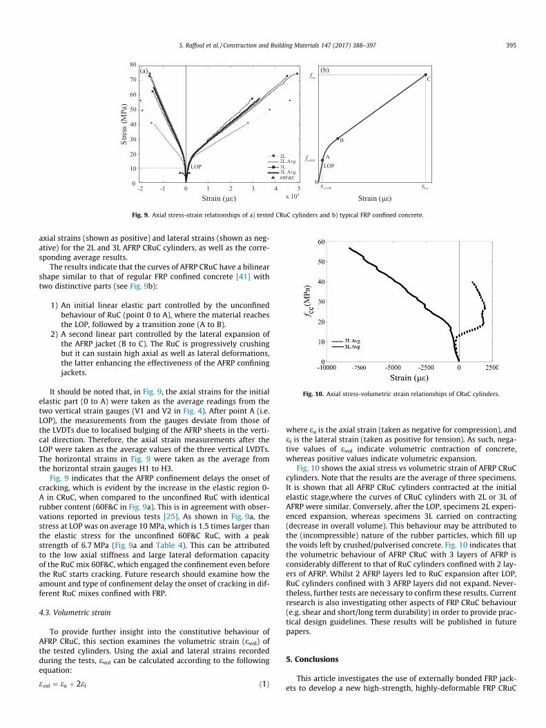
Fig. 9. Axial stress-strain relationships of a) tested CRuC cylinders and b) typical FRP confined concrete.
Fig. 10. Axial stress-volumetric strain relationships of CRuC cylinders.
S. Raffoul et al. / Construction and Building Materials 147 (2017) 388–397 395
axial strains (shown as positive) and lateral strains (shown as neg-ative) for the 2L and 3L AFRP CRuC cylinders, as well as the corre-sponding average results.
The results indicate that the curves of AFRP CRuC have a bilinearshape similar to that of regular FRP confined concrete [41] withtwo distinctive parts (see Fig. 9b):
1) An initial linear elastic part controlled by the unconfinedbehaviour of RuC (point 0 to A), where the material reachesthe LOP, followed by a transition zone (A to B).
2) A second linear part controlled by the lateral expansion ofthe AFRP jacket (B to C). The RuC is progressively crushingbut it can sustain high axial as well as lateral deformations,the latter enhancing the effectiveness of the AFRP confiningjackets.
It should be noted that, in Fig. 9, the axial strains for the initialelastic part (0 to A) were taken as the average readings from thetwo vertical strain gauges (V1 and V2 in Fig. 4). After point A (i.e.LOP), the measurements from the gauges deviate from those ofthe LVDTs due to localised bulging of the AFRP sheets in the verti-cal direction. Therefore, the axial strain measurements after theLOP were taken as the average values of the three vertical LVDTs.The horizontal strains in Fig. 9 were taken as the average fromthe horizontal strain gauges H1 to H3.
Fig. 9 indicates that the AFRP confinement delays the onset ofcracking, which is evident by the increase in the elastic region 0-A in CRuC, when compared to the unconfined RuC with identicalrubber content (60F&C in Fig. 9a). This is in agreement with obser-vations reported in previous tests [25]. As shown in Fig. 9a, thestress at LOP was on average 10 MPa, which is 1.5 times larger thanthe elastic stress for the unconfined 60F&C RuC, with a peakstrength of 6.7 MPa (Fig. 9a and Table 4). This can be attributedto the low axial stiffness and large lateral deformation capacityof the RuC mix 60F&C, which engaged the confinement even beforethe RuC starts cracking. Future research should examine how theamount and type of confinement delay the onset of cracking in dif-ferent RuC mixes confined with FRP.
4.3. Volumetric strain
To provide further insight into the constitutive behaviour ofAFRP CRuC, this section examines the volumetric strain (evol) ofthe tested cylinders. Using the axial and lateral strains recordedduring the tests, evol can be calculated according to the followingequation:
evol ¼ ea þ 2el ð1Þ
where ea is the axial strain (taken as negative for compression), andel is the lateral strain (taken as positive for tension). As such, nega-tive values of evol indicate volumetric contraction of concrete,whereas positive values indicate volumetric expansion.
Fig. 10 shows the axial stress vs volumetric strain of AFRP CRuCcylinders. Note that the results are the average of three specimens.It is shown that all AFRP CRuC cylinders contracted at the initialelastic stage,where the curves of CRuC cylinders with 2L or 3L ofAFRP were similar. Conversely, after the LOP, specimens 2L experi-enced expansion, whereas specimens 3L carried on contracting(decrease in overall volume). This behaviour may be attributed tothe (incompressible) nature of the rubber particles, which fill upthe voids left by crushed/pulverised concrete. Fig. 10 indicates thatthe volumetric behaviour of AFRP CRuC with 3 layers of AFRP isconsiderably different to that of RuC cylinders confined with 2 lay-ers of AFRP. Whilst 2 AFRP layers led to RuC expansion after LOP,RuC cylinders confined with 3 AFRP layers did not expand. Never-theless, further tests are necessary to confirm these results. Currentresearch is also investigating other aspects of FRP CRuC behaviour(e.g. shear and short/long term durability) in order to provide prac-tical design guidelines. These results will be published in futurepapers.
5. Conclusions
This article investigates the use of externally bonded FRP jack-ets to develop a new high-strength, highly-deformable FRP CRuC

396 S. Raffoul et al. / Construction and Building Materials 147 (2017) 388–397
for structural applications. Sixty RuC and six CRuC standard cylin-ders were tested in axial compression to evaluate the behaviour ofunconfined and confined RuC. Based on the results of this study,the following conclusions can be drawn:
� The stress-strain behaviour of cylinders made with concretewith low rubber contents (less than 18% of the total aggregatevolume) is similar to that of conventional concrete. However,even such modest replacement volumes led to large reductionsin compressive strength (up to 40% for mix 20C with 11% totalaggregate replacement).
� Replacing aggregates with rubber also reduces the axial strainof the resulting concrete at peak stress. This effect was particu-larly evident for high rubber contents (>27% of the total aggre-gate volume). As rubber content was increased, the reduction inaxial strains was accompanied by a premature onset of localisedmicro-cracking.
� The difference in compressive strength when comparing fine orcoarse aggregate replacement with similar overall aggregatereplacement is marginal. The combined replacement of coarseand fine aggregate is the best option to maximise rubber con-tent and deformability potential, while achieving adequateworkability.
� Replacing aggregates with rubber increases the lateral deforma-tion capacity of RuC by up to 300% over the plain mix. Confiningsuch RuC with two and three layers of AFRP increased the com-pressive strength by up to 10.1 times (fcc = 75 MPa) over thecontrol mix. Moreover, average axial ultimate strains of up to5% were achieved (i.e. 14 times more than conventional con-crete). This indicates that CRuC is suitable for structural applica-tions where high deformability is required.
� The lateral confinement modified the volumetric behaviour ofCRuC. Specimens with 2 layers of AFRP had volumetric expan-sion after the LOP, whereas those with 3 layers of AFRP main-tained volumetric contraction. This behaviour can beattributed to the incompressible nature of the rubber particles,which can fill the voids in concrete under heavy confinement,leading to overall contraction of the cylinders with 3 AFRPlayers.
The results of this study confirm the feasibility of developinghighly deformable AFRP CRuC with sufficient strength for struc-tural applications. However, due to the limited experimental data,future research should verify the variability of results and possiblesize effects. Moreover, the use of more widely available confiningmaterials such as Carbon FRP could be also studied.
Acknowledgements
The research leading to these results has received funding fromthe European Union Seventh Framework Programme [FP7/2007-2013] under grant agreement n� 603722 and the European Union’sHorizon 2020 research and innovation programme under theMarie Sklodowska-Curie grant agreement n� 658248. The authorsalso thank Richard Morris from Tarmac UK for providing the Port-land Limestone Cement (CEM II 52.5 N). The AFRP system waskindly provided by Weber Saint-Gobain, UK.
References
[1] Business T. Global tire sales to grow 4.3% per year. Tire Business, 1/17/2014;2014.
[2] ETRA. The European Tyre Recycling Association. Available at: http://www.etra-eu.org [Last accessed: 10/06/2014].
[3] Directive (EC) 98/2008 of the European Parliament and of the Council of 19November 2008 on waste and replacing certain Directives [2008] OJ L312/3.
[4] B.S. Thomas, R.C. Gupta, A comprehensive review on the applications of wastetire rubber in cement concrete, Renew. Sustain. Energy Rev. 54 (2016) 1323–1333.
[5] O. Sengul, Mechanical behavior of concretes containing waste steel fibersrecovered from scrap tires, Constr. Build. Mater. 122 (2016) 649–658.
[6] S.-S. Huang, H. Angelakopoulos, K. Pilakoutas, I. Burgess, Reused tyre polymerfibre for fire-spalling mitigation, Appl. Struct. Fire Eng. (2016).
[7] D. Goulias, A.-H. Ali, Evaluation of rubber-filled concrete and correlationbetween destructive and nondestructive testing results, Cem. Concr.Aggregates 20 (1) (1998) 140–144.
[8] K.S. Son, I. Hajirasouliha, K. Pilakoutas, Strength and deformability of wastetyre rubber-filled reinforced concrete columns, Constr. Build. Mater. 25 (1)(2011) 218–226.
[9] F. Liu, W. Zheng, L. Li, W. Feng, G. Ning, Mechanical and fatigue performance ofrubber concrete, Constr. Build. Mater. 47 (2013) 711–719.
[10] J. Xue, M. Shinozuka, Rubberized concrete: a green structural material withenhanced energy-dissipation capability, Constr. Build. Mater. 42 (2013) 196–204.
[11] K.B. Najim, M.R. Hall, Mechanical and dynamic properties of self-compactingcrumb rubber modified concrete, Constr. Build. Mater. 27 (1) (2012) 521–530.
[12] M.K. Batayneh, I. Marie, I. Asi, Promoting the use of crumb rubber concrete indeveloping countries, Waste Manage. 28 (11) (2008) 2171–2176.
[13] Z.K. Khatib, F.M. Bayomy, Rubberized Portland cement concrete, J. Mater. Civ.Eng. 11 (3) (1999) 206–213.
[14] E. Ganjian, M. Khorami, A.A. Maghsoudi, Scrap-tyre-rubber replacement foraggregate and filler in concrete, Constr. Build. Mater. 23 (5) (2009) 1828–1836.
[15] M.C. Bignozzi, F. Sandrolini, Tyre rubber waste recycling in self-compactingconcrete, Cem. Concr. Res. 36 (4) (2006) 735–739.
[16] G. Li, M.A. Stubblefield, G. Garrick, J. Eggers, C. Abadie, B. Huang,Development of waste tire modified concrete, Cem. Concr. Res. 34 (12)(2004) 2283–2289.
[17] H.A. Toutanji, The use of rubber tire particles in concrete to replace mineralaggregates, Cement Concr. Compos. 18 (2) (1996) 135–139.
[18] P. Sukontasukkul, C. Chaikaew, Properties of concrete pedestrian block mixedwith crumb rubber, Constr. Build. Mater. 20 (7) (2006) 450–457.
[19] A. Turatsinze, J.L. Granju, S. Bonnet, Positive synergy between steel-fibres andrubber aggregates: effect on the resistance of cement-based mortars toshrinkage cracking, Cem. Concr. Res. 36 (9) (2006) 1692–1697.
[20] A.E. Richardson, K.A. Coventry, G. Ward, Freeze/thaw protection ofconcrete with optimum rubber crumb content, J. Cleaner Prod. 23 (1) (2012)96–103.
[21] C. Pierce, M. Blackwell, Potential of scrap tire rubber as lightweight aggregatein flowable fill, Waste Manage. 23 (3) (2003) 197–208.
[22] H. Zhu, N. Thong-On, X. Zhang, Adding crumb rubber into exterior wallmaterials, Waste Manage. Res. 20 (5) (2002) 407–413.
[23] P. Sukontasukkul, Use of crumb rubber to improve thermal and soundproperties of pre-cast concrete panel, Constr. Build. Mater. 23 (2) (2009) 1084–1092.
[24] O. Youssf, M.A. ElGawady, J.E. Mills, X. Ma, An experimental investigation ofcrumb rubber concrete confined by fibre reinforced polymer tubes, Constr.Build. Mater. 53 (2014) 522–532.
[25] G. Li, S.-S. Pang, S.I. Ibekwe, FRP tube encased rubberized concrete cylinders,Mater. Struct. 44 (1) (2011) 233–243.
[26] R. Abendeh, H.S. Ahmad, Y.M. Hunaiti, Experimental studies on the behavior ofconcrete-filled steel tubes incorporating crumb rubber, J. Constr. Steel Res. 122(2016) 251–260.
[27] A. Duarte, B. Silva, N. Silvestre, J. de Brito, E. Júlio, J. Castro, Experimental studyon short rubberized concrete-filled steel tubes under cyclic loading, Compos.Struct. (2015).
[28] A. Moustafa, M.A. ElGawady, Strain rate effect on properties of rubberizedconcrete confined with glass fiber-reinforced polymers, J. Compos. Constr.04016014 (2016).
[29] L. Lam, J. Teng, Ultimate condition of fiber reinforced polymer-confinedconcrete, J. Compos. Constr. 8 (6) (2004) 539–548.
[30] S. Raffoul, R. Garcia, K. Pilakoutas, M. Guadagnini, N.F. Medina, Optimisation ofrubberised concrete with high rubber content: an experimental investigation,Constr. Build. Mater. 124 (2016) 391–404.
[31] Innovative Use of all Tyre Components in Concrete, Anagennisi Project. 2014.Available at: http://www.anagennisi.org/.
[32] BSI 197-1:2011. Cement. Part 1: Composition, specifications and conformitycriteria for common cements. 2011, BS EN 197 Part 1. London UK.
[33] Sika Limited. Sika Viscoflow 2000. Product Data Sheet. Edition-15/10/2014;Identification no: 02 13 01 01 100 0 001325. Available at https://goo.gl/kMfHcU [Last accessed 10/12/2015].
[34] Sika Limited. Sika Viscoflow 1000. Product Data Sheet. Edition-21/05/2015;Identification no: 02 13 01 01 100 0 000853. Available at https://goo.gl/mMDfay [Last accessed 10/12/2015].
[35] ASTM Standard C136, Standard Test Method for Sieve Analysis of Fine andCoarse Aggregates, ASTM International, West Conshohocken, PA, 2006, http://dx.doi.org/10.1520/C0136-06.
[36] BSI 1097-6: 2013. Tests for mechanical and physical properties of aggregates.Determination of particle density and water absorption. 2013, BS EN 1097 Part6. London, UK.
[37] BSI 933-3:2012. Tests for geometrical properties of aggregates. Determinationof particle shape – Flakiness index. 2012, BS EN 933 Part 3. London, UK.

S. Raffoul et al. / Construction and Building Materials 147 (2017) 388–397 397
[38] BSI 1097-3:1998. Tests for mechanical and physical properties of aggregates:Determination of loose bulk density and voids. 1998, BS EN 1097 Part 3.London, UK.
[39] R. Garcia, K. Pilakoutas, I. Hajirasouliha, M. Guadagnini, N. Kyriakides, M.A.Ciupala, Seismic retrofitting of RC buildings using CFRP and post-tensionedmetal straps: shake table tests, Bull. Earthquake Eng. (2015) 1–27.
[40] A. Turatsinze, M. Garros, On the modulus of elasticity and strain capacity ofself-compacting concrete incorporating rubber aggregates, Resour. Conserv.Recycl. 52 (10) (2008) 1209–1215.
[41] J. Teng, J.-F. Chen, S.T. Smith, L. Lam, FRP: strengthened RC structures, Front.Phys. 1 (2002).