behaviour of water in jet fuel 2013 - ceres home
TRANSCRIPT

Behaviour of Water in Jet Fuel
A Literature Review
S. Baenaa,∗, S. L. Repettob, Dr C.P. Lawsona,∗∗, Dr. J. K.-W. Lamc
aCranfield University, Cranfield, Bedfordshire MK43 0AL, UKbUniversity of West England, Coldharbour Lane, Bristol BS16 1QY, UK
cAirbus Operations Limited, New Filton House, Filton, Bristol BS99 7AR, UK
Abstract
This review gives a detailed account of the different types of water con-
taminated fuel and the conditions that bring about each form of contamina-
tion. It also considers studies that have been done to date that investigate
the physics behind the behaviour of water in different hydrocarbons and jet
fuel at low temperatures.
Keywords:
Aviation fuel, Jet A-1, low temperatures, water, ice, hydrocarbons, fuel
system.
Nomenclature
µ Viscosity
ρ Density
d Diameter
∗Corresponding author∗∗Principal corresponding author
Preprint submitted to Progress in Aerospace Sciences April 11, 2012
g Gravity Acceleration
v Velocity
1. Introduction
It is commonly accepted throughout the aviation industry that a mixture
of water and jet fuel in any form is undesirable and potentially hazardous.
Although jet engines are capable of burning a mixture of fuel and water, the
water content must be kept below tolerable levels. Entrained or generated
water in the fuel system, when combined with very low temperatures, may
result in ice formation within the aircraft fuel system.
There are a number of systems in place to prevent the adherence of ice
to the fuel system surfaces. Civil aircraft prevent ice build-up on fuel filters
within the engine frame using fuel-oil or fuel-air heat exchangers. Aircraft
feed pumps have protective pump mesh strainers with bypasses, that ensure
uninterrupted fuel flow to the engine in the event of ice build-up and mesh
strainer blockage. Pipes and tanks in the fuel feeding system of some aircraft
use electric fuel line heaters. If conditions are extremely cold, anti-icing addi-
tives are mixed with the jet fuel in small quantities to prevent the formation
of ice in the fuel.
These techniques effectively address the problem, but neglect the root
cause. When a Boeing 777 crash landed at Heathrow airport in January
2008, the Air Accident Investigation Branch (AAIB) final report [1] raised
concerns about the lack of understanding of the nature and behaviour of wa-
2

ter in jet fuel. Hence a number of research programmes, considered in this
review, have been initiated to further understand the behaviour of water at
low temperatures in different hydrocarbons and jet fuels.
In Section 2 the reader can find a general overview of jet fuels currently
utilised in the civil aviation industry. Section 3 explains the different forms
of water contamination in jet fuel. A detailed study of the effects of temper-
ature and humidity on the hygroscopicity of jet fuel is included in Section
4. Section 5 is the result of an extensive literature search carried out to
review the current understanding of water dropout and nucleation (i.e. ice
formation) in aviation fuels. Section 6 gives a brief overview of ice accretion
on metal surfaces and fuel systems.
2. Kerosene Jet Fuel
There are many different kerosene based jet fuels used in the aviation in-
dustry [2]. The current specifications [3–5] and designations for conventional
jet-engined commercial aircraft are illustrated in Table 1. These specifica-
tions are alike in most respects, but differ significantly in the lower freezing
point, flash point, and viscosity. Such characteristics are set to endure the
low temperatures encountered in different countries.
3
Fuel Grade Country/Region Specification
Jet A USA ASTM D1655
Jet A-1 Worlwide ASTM D1655, DEF STAN 91-91
TS-1 Russia∗ GOST 10227
Jet Fuel no.3 China GB 6537
Jet A-1 Canada CAN/CGSB-3.23
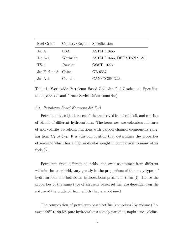
Table 1: Worldwide Petroleum Based Civil Jet Fuel Grades and Specifica-
tions (Russia∗ and former Soviet Union countries)
2.1. Petroleum Based Kerosene Jet Fuel
Petroleum-based jet kerosene fuels are derived from crude oil, and consists
of blends of different hydrocarbons. The kerosenes are colourless mixtures
of non-volatile petroleum fractions with carbon chained components rang-
ing from C9 to C14. It is this composition that determines the properties
of kerosene which has a high molecular weight in comparison to many other
fuels [6].
Petroleum from different oil fields, and even sometimes from different
wells in the same field, vary greatly in the proportions of the many types of
hydrocarbons and individual hydrocarbons present in them [7]. Hence the
properties of the same type of kerosene based jet fuel are dependent on the
nature of the crude oil from which they are obtained.
The composition of petroleum-based jet fuel comprises (by volume) be-
tween 99% to 99.5% pure hydrocarbons namely paraffins, naphthenes, olefins,
4
and aromatics. It is the latter group that is thought to have an effect on the
solubility of water in jet fuel, as discussed in Section 4.3.2.
Approximately 0.5% to 1% of petroleum-based jet fuel consist of non-
hydrocarbon components such as naphthenic acids and compounds of sul-
phur, sodium, lead and bromine [6]. Raw kerosene must meet the limits
of non-hydrocarbon components set by the Defence Standard (DEF STAN)
91-91 (or equivalent, Table 1) [3, 4]. In most cases the kerosene has to be
treated in the refinery (by hydrotreating or Merox-Processing) to meet these
targets. The resulting chemical composition of jet fuel varies slightly with
the different treatments, and this was thought to have an impact on the fuel
hygroscopicity. However, recent studies have shown that the different treat-
ments do not have a significant effect on the amount of water absorbed by
the fuel [8].
2.2. Gas to Liquid Synthetic Kerosene Jet Fuel
Synthetic paraffinic kerosene (SPK) jet fuel is currently being derived
from natural gas using the gas to liquid (GTL) Fischer-Tropsch (FT) pro-
cess [9] followed by downstream processing [10]. Coal (CTL) and biomass
(BTL) are also less widely used alternatives to natural gas.
The FT process creates mainly straight chain hydrocarbons [11]. The
lack of aromatics and cyclo-paraffins in synthetic kerosenes yields fuels that
are below the minimum density specification requirement set at 775 kg m−3
[12]. Aromatics are also responsible for swelling elastomers used in aircraft
5

fuel systems. Hence the lack of aromatics in the fuel may cause some of these
elastomers to shrink, which may lead to fuel leaks [11].
The disadvantages discussed cease to exist if FT SPK fuels are blended
with conventional jet fuels. Specific approved FT SPK fuels are currently
being used in some commercial flights as a 50/50 blend with petroleum de-
rived jet fuels, with at least 8% of aromatics (by volume) in the final blend
[3, 4, 13]. The blend with petroleum derived jet fuel is termed semi-synthetic
jet fuel (SSJF).
The solubility of water in SSJFs is approximately 25% to 30% lower com-
pared with conventional Jet A and Jet A-1 fuels [12]. The solubility of water
in SSJFs fuels is dependent on the conventional jet fuel used in the blend.
The FT SPK contain no heteroatoms, aromatics nor any other polar com-
pounds [12]. As discussed in detail in Section 4, such compounds are believed
to increase water solubility in petroleum based jet fuels. However, research
is still required to determine the behaviour of water in synthetic jet fuels.
2.3. Biokerosene Jet Fuel
Biokerosenes are hydroprocessed esters and fatty acids (HEFA) derived
from plant oils and animal fats [14]. During the complex process of turning
biomass into fuel, plant oils and animal fats are turned into a paraffin wax
that is later submitted to the FT process. As a result, HEFA SPK is almost
identical to FT SPK.
6
Biokerosenes were approved in the summer of 2011 [3, 4, 13]. As with
FT SPK, aromatics are not found in biokerosenes. Hence for the reasons
discussed in Section 2.2, biomass kerosenes are also being blended with con-
ventional commercial jet fuel. Specific approved biokerosenes, namely BTL
SPK and HEFA SPK, have been introduced in commercial aircraft as a 50/50
blend with petroleum derived jet fuels [15].
The solubility of water in both HEFA and BTL SPK fuels may be com-
parable to FT SPK, and is dependent on the conventional jet fuel used in the
blend. Nonetheless, the hygroscopicity of biokerosenes needs further research.
3. Forms of Water Contamination in Jet Fuel
Water can be present in fuel in three forms: dissolved in the fuel, sus-
pended in fuel as water-in-fuel emulsions, or free water. Dissolved water is
invisible to the naked eye, and is considered a constituent of jet fuel that
vaporises during combustion [6]. Suspended water appears as a dull, hazy,
or cloudy appearance that takes time to coalesce or settle down. Free water,
being denser than fuel, forms a separate layer at the bottom of fuel tanks.
Water-in-fuel emulsions and free water are regarded as fuel contaminants,
and are managed through rigorous Quality Control (QC) measures [16].
Water in aviation fuel comes from numerous different sources. Each year,
a large amount of fuel is moved globally via pipeline networks, rail, ship,
7
road or a combination of these methods [7]. Even if the jet fuel is dry as it
leaves the refinery, it may pick up free water during its transit and storage
through the transport network [6].
Means of water contamination of jet fuel include [17]:
• Rain water entering through the seals in poorly maintained floating-
roof tanks
• Rain water entering through hatches of fuel storage tanks
• Water left behind after cleaning operations in tanks or transport vehi-
cles due to poor personnel procedures
• Condensation of water from moist air to the tank walls in vented fixed
roof storage tanks
• At low temperatures, precipitation of dissolved water from the fuel
itself, as discussed in Section 4.
3.1. Dissolved Water
Water is not soluble in jet fuel. A fuel is said to be saturated with water
when it has dissolved all the H2O molecules it can hold under certain condi-
tions. For example, at 21 ◦C and atmospheric pressure, a saturated kerosene
based fuel contains approximately 40 to 80 (water) parts per million, (ppm)
[2].
Like many other components in fuel, dissolved water is regarded as an-
other fuel constituent, and is not considered a contaminant as long as it is
8

maintained in a dissolved state [2]. Dissolved water cannot be removed by
any mechanical process such as settling, filtering or separation and so any
attempt to dry jet fuel in these ways is futile.
3.2. Free Water and Water-in-Fuel Emulsions
Water is sparingly miscible with hydrocarbon fuel and since water is
denser than fuel, any free water within the fuel forms a lower layer sepa-
rated from the jet fuel upper layer. If jet fuel and water are mixed, they will
separate back to the two layers.
An emulsion is a mixture of two or more immiscible liquids where one is
dispersed as droplets, of microscopic or ultra-microscopic size (in this case,
0.1µm to 100µm water droplets), in the continuous phase of the other (jet
fuel).
Emulsions of water droplets in jet fuel are formed by a) dissolution of
water from the fuel (fully explained in Section 4.5) and b) mechanical means
such as agitation as jet fuel passes through different components in the fuel
system. When jet fuel goes through pumps in the aircraft, free water in the
fuel is separated into a very fine dispersion of droplets of different sizes that
lie in the range of 50µm down to 5µm [7].
The rate of settling of finely dispersed water from fuel is subject to Stoke’s
Law; giving the movement of water droplets a direct proportionality to their
diameter, and an inverse proportionality to the fuel’s density and viscosity
9
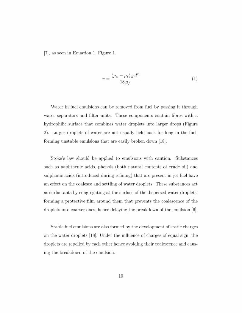
[7], as seen in Equation 1, Figure 1.
v =(ρw − ρf ) g d
2
18µf
(1)
Water in fuel emulsions can be removed from fuel by passing it through
water separators and filter units. These components contain fibres with a
hydrophilic surface that combines water droplets into larger drops (Figure
2). Larger droplets of water are not usually held back for long in the fuel,
forming unstable emulsions that are easily broken down [18].
Stoke’s law should be applied to emulsions with caution. Substances
such as naphthenic acids, phenols (both natural contents of crude oil) and
sulphonic acids (introduced during refining) that are present in jet fuel have
an effect on the coalesce and settling of water droplets. These substances act
as surfactants by congregating at the surface of the dispersed water droplets,
forming a protective film around them that prevents the coalescence of the
droplets into coarser ones, hence delaying the breakdown of the emulsion [6].
Stable fuel emulsions are also formed by the development of static charges
on the water droplets [18]. Under the influence of charges of equal sign, the
droplets are repelled by each other hence avoiding their coalescence and caus-
ing the breakdown of the emulsion.
10
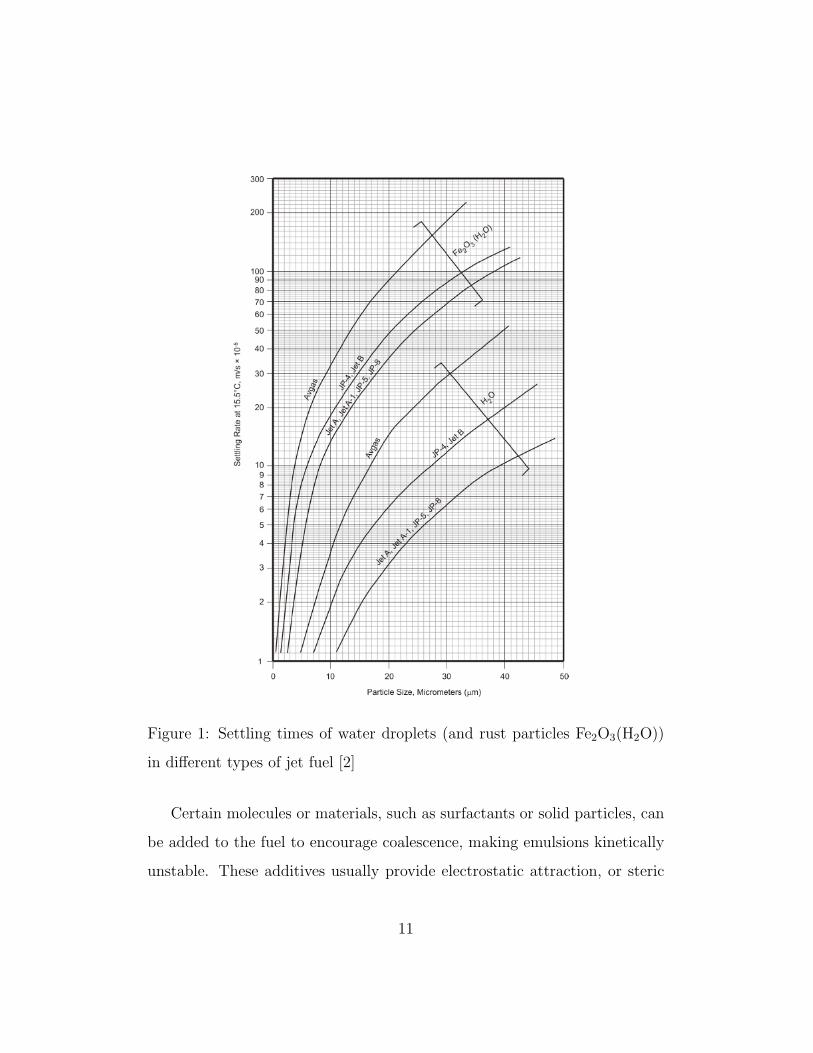
Figure 1: Settling times of water droplets (and rust particles Fe2O3(H2O))
in different types of jet fuel [2]
Certain molecules or materials, such as surfactants or solid particles, can
be added to the fuel to encourage coalescence, making emulsions kinetically
unstable. These additives usually provide electrostatic attraction, or steric
11
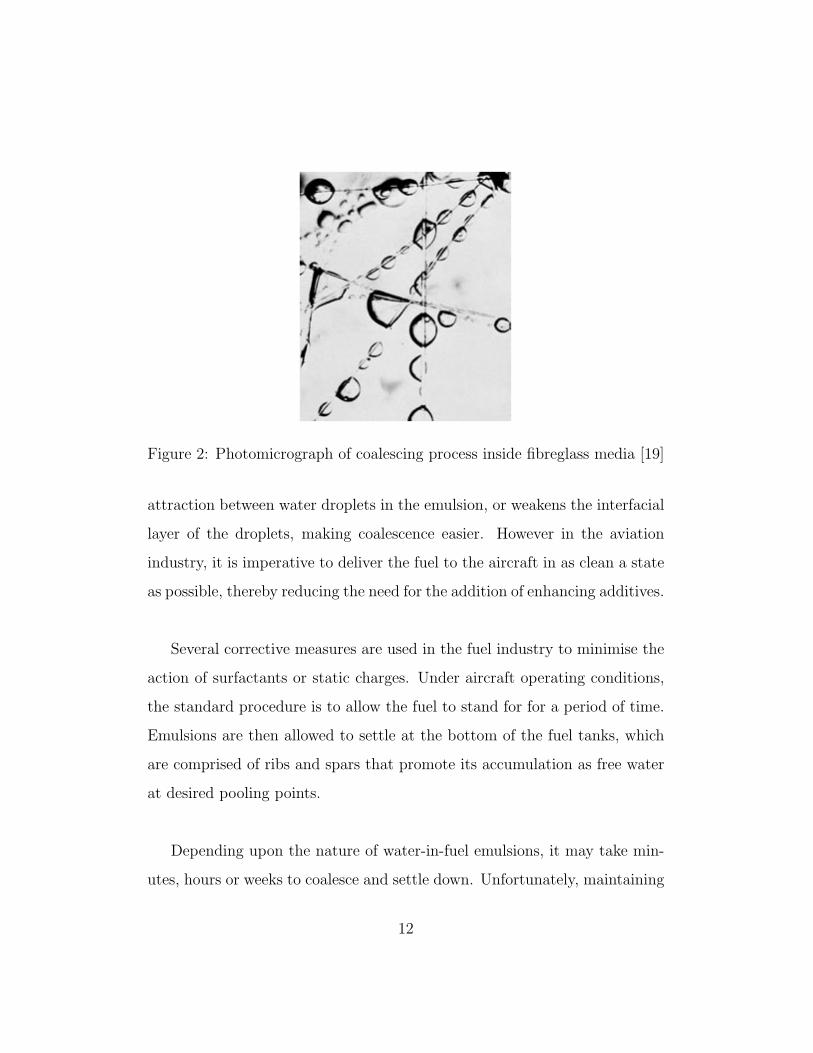
Figure 2: Photomicrograph of coalescing process inside fibreglass media [19]
attraction between water droplets in the emulsion, or weakens the interfacial
layer of the droplets, making coalescence easier. However in the aviation
industry, it is imperative to deliver the fuel to the aircraft in as clean a state
as possible, thereby reducing the need for the addition of enhancing additives.
Several corrective measures are used in the fuel industry to minimise the
action of surfactants or static charges. Under aircraft operating conditions,
the standard procedure is to allow the fuel to stand for for a period of time.
Emulsions are then allowed to settle at the bottom of the fuel tanks, which
are comprised of ribs and spars that promote its accumulation as free water
at desired pooling points.
Depending upon the nature of water-in-fuel emulsions, it may take min-
utes, hours or weeks to coalesce and settle down. Unfortunately, maintaining
12
an aircraft for weeks or even hours on tarmac is not cost-effective in today’s
civil aviation industry, where turnarounds can be as short as 30 minutes for
smaller commercial aircraft. Hence the pooled, free water is routinely picked
up and fed to the engine in a mixture with the fuel. This is part of current
commonly adopted water management and is achieved using scavenging jet
pumps. Free water in pooling points is also drained on the ground during
routine maintenance.
4. Hygroscopicity of Jet Fuel
The hygroscopic nature of jet fuel refers to its ability to attract mois-
ture from the air and surroundings. The reversible hygroscopicity of jet fuel
strongly depends on atmospheric conditions such as the temperature and
relative humidity to which the jet fuel is subjected. Any variation in these
conditions will cause phase transitions of the water contained in the fuel.
It is important to understand the difference between solubility and hygro-
scopicity. The solubility of water in fuel refers to the degree to which water
dissolves in fuel to make a solution, and is dependent upon the chemical com-
position of the fuel. Once the hygroscopic nature of jet fuel attracts moist
air to its surface, the water molecules in direct contact with the hydrocarbon
based fuel go into solution.
13
4.1. Effect of Relative Humidity in the Solubility of Water in Jet Fuel
The amount of water generated in fuel depends on the relative humidity
(RH) of the air above the fuel. When the fuel is not in equilibrium with the
atmosphere above its surface, and its RH is lower than the RH of the air in
the ullage, jet fuel absorbs moisture from the air to regain a state of equilib-
rium according to the surrounding conditions [7]. This process is reversible,
and the dissolved water is taken out of solution when the RH of the air above
the fuel decreases, i.e. becomes lower than the RH of the fuel.
To have an idea of the effect of moist air within a fuel tank, fuel in direct
contact with air with a RH of 50% contains only half as much water as water-
saturated fuel at that temperature, however fuel tends to enter the tanks of
the aircraft already saturated due to its contamination during transport from
the refinery [20].
The amount of free water generated in fuel storage tanks can be signifi-
cant if the tanks are located in humid climates. Smith [7] argues that daily
temperature changes in countries with such climates are fairly small and the
water released at night, is then re-absorbed during the day, i.e. it is “self-
compensating”. However, more recently Oreshenkov [21] has demonstrated
that over a period of a few months, cyclic temperature changes produce a
significant amount of water accumulation in fuel tanks.
14

4.2. Effect of Temperature in the Solubility of Water in Jet Fuel
As shown in Figure 4, there is a connection between solubility of water
in fuel and temperature. The greater the solubility of H2O in the fuel, the
higher the temperature at which dissociation of water particles and hydro-
carbon components takes place (i.e. reversible hygroscopicity).
(a) t = 0 min (b) t = 14 min
(c) t = 30 min (d) t = 58 min
Figure 3: Water dispersed in Jet A-1 fuel [22]
Water released from fuel appears as a fine cloud of minute droplets. Lao
et al. [22] measured the relative transparency of 20 L of water saturated Jet
15

A-1 fuel as a function of temperature. It was observed that at temperatures
above 14 ◦C the water was completely dissolved and the fuel had a clear ap-
pearance. As seen in Figure 3, at temperatures below 14 ◦C, excess water
precipitated out forming a fog phenomena, hence reducing the transparency
of the fuel. Measured data was in agreement with the solubility of water in
fuel depicted in Figure 4.
4.3. Effects of Different Hydrocarbons in the Solubility of Water in Jet Fuel
Hydrocarbons are organic compounds formed of carbon and hydrogen
atoms. As discussed in Section 2, there are three main types of hydrocar-
bons in jet fuel; paraffins (≈ 60%), naphthenes (≈ 20%), and aromatics (≈
20%).
The main difference between each class of hydrocarbons is the way in
which the carbon atoms are connected to each other (as depicted in Figure
5), which dictates the ratio of hydrogen to carbon atoms within the molecule.
This determines the physical and chemical properties of the fuel, including
water solubility [6].
4.3.1. Paraffins & Naphthenes
Paraffins and naphthenes - also known as alkanes - are the major com-
ponents of aviation fuels [6]. They consist of singly bonded carbon chains
or rings in which each atom is fully saturated with hydrogen (i.e. saturated
16

Figure 4: Water solubility vs. temperature for aircraft fuel, at 100% RH [2]
hydrocarbons). Paraffins can either be linear or branched chain molecules,
and the naphthenes have at least one saturated carbon ring. The carbon-
carbon and carbon-hydrogen bonds in these molecules do not possess strong
permanent dipoles [23]; therefore this class of molecules interact with each
17

other via the weakest of intermolecular forces, resulting from the temporary
movement of electrons (London dispersion forces).
(a) Paraffins (b) Nephthenes
(c) Olefins (d) Aromatics
Figure 5: Examples of hydrocarbons commonly found in jet fuel
18
4.3.2. Olefins & Aromatics
Olefins and aromatics (Figure 5) are unsaturated hydrocarbons because
they contain fewer hydrogen atoms than the corresponding alkanes, and
carbon-carbon double bonds, called π bonds.
The aromatics in particular have a characteristic ring of six carbon atoms
(benzene), about which the π electron cloud is evenly distributed. The quan-
tity of aromatic compounds in Jet A/A1 is limited to a maximum of 25%
by volume, because of their tendency to form coke deposits on combustor
surfaces, to create smoke when burned, and to contribute to high-luminosity
flames [3, 4].
4.4. Water Solubility in Jet Fuel
The hygroscopic capacity of jet fuel is determined by the water solubility
of the individual hydrocarbon components. Because water is sparingly sol-
uble in hydrocarbons, accurate determinations are difficult to achieve, and
remains an active and challenging area of research [24].
Water possesses a strong permanent dipole because of the difference in
electronegativity that exists between the hydrogen and oxygen atoms. There-
fore, relatively strong attractive interactions exist between adjacent water
molecules, leading to extended hydrogen bonding networks. Experimental
observations of water dissolution in hydrocarbons have led to a variety of
theoretical models which all require, as a first step, the disruption of these
hydrogen bonding networks [24–31].
19

The energy associated with dissolving water - enthalpy of solution - in a
range of unbranched alkanes has only a weak dependence on the number of
carbon atoms present (i.e. C7 − C12 = 34.9 ± 1.1 kJ mol−1 at 298K) [28].
The magnitude of the enthalpy of solution is comparable to the hydrogen
bond energy, suggesting that the dissolution of n water molecules requires
the breaking of n hydrogen bonds [31].
The enthalpy of solution of water in both alkylbenzenes and alkenes de-
creases by approximately 11 and 2 kJ mol−1, respectively. The energetic cost
of disrupting the hydrogen bond network of water is offset by attractive elec-
trostatic interactions with these hydrocarbons. It has long been recognised
that extended π electron systems, such as those encountered within alkyl-
benzenes, form hydrogen bonds with water [29, 32, 33]. A weaker form of
that interaction, between water and the π bond of an alkene, may account
for the ∼ 2 kJ mol−1 enthalpy reduction [30].
The formation of attractive electrostatic interactions between water and
π-aromatic systems would account for the enhanced solubility of water in
alkylbenzenes, relative to both paraffins and naphthenes.
There are a number of studies that compare the solubility of water in
different hydrocarbons [8, 22, 24–39]. Most recently, Carpenter et al. [8]
showed that aromatic hydrocarbons absorb up to seven times more dissolved
water than the alkane or cycloalkane with a comparable number of carbon
20

atoms.
As depicted in Figure 6, water solubility increases with the proportion
of aromatic hydrocarbons, but not in a linear fashion. Figure 6 also reflects
the behaviour of water solubility in hydrocarbons in general, suggesting that
this physical property is non-colligative i.e. not simply dependent upon the
number of molecules [29, 38].
Figure 6: Water solubility in n-Octane/Toluene mixtures at 15.5◦C
21

4.5. Water Cycles in Aircraft Fuel Tanks
Fuel in the aircraft system is subject to significant changes in temperature
and exposure to humid air within the tanks. As a result of such variations
and given the reversible hygroscopicity of fuel during flight, there is a contin-
uous process of absorption and spontaneous liberation of the dissolved water
[2].
At high altitudes and low temperatures, water from the fuel evaporates
until its concentration in the fuel reaches equilibrium with the concentration
of water in the air within the fuel tanks. This evaporation is followed by the
condensation of the water in the ullage on the metal walls of the tanks as
well as the cold surface of the fuel. A continuous process of evaporation from
fuel and condensation of the surplus water vapour in the space above the
kerosene is established. The evaporation process continues until the pressure
of the water vapour above the jet fuel attains an equilibrium established by
the humidity and temperature of the air [2, 18].
Separation of water molecules from fuel also takes place as an emulsion.
If the fuel surfactants concentration is limited, the water droplets settle on
the bottom of the tanks (as free water) in quiescent conditions, or remain
suspended in the fuel otherwise [1, 18]. Below freezing temperatures, the
small droplets turn into ice crystals within the fuel and the condensed water
freezes on the walls or forms small ice particles on the surface of the fuel by
the process of nucleation.
22

5. Water Nucleation in Fuels
Nucleation is the process by which nuclei are formed, usually in solution.
The term nucleus as used in the stem of the word refers to the formation of a
small, solid phase collection of atoms, molecules or ions during precipitation,
capable of spontaneous growth.
The metastable state of a body or system, in this case hygroscopic wa-
ter, refers to the condition of the water existing at an energy level in the
liquid state which is above that of a more stable condition, i.e. ice. It would
take a small amount of energy to induce a transition to the more stable state.
Metastable states of solutions or any liquid involve both supersaturated
and supercooled solutions. Hygroscopic water in jet fuel can exist in a super-
cooled metastable phase, when supercooled water droplets prevail inside the
crystalline domain of stability [40], i.e. at temperatures below its freezing
point.
For a new phase to appear, an interface must be formed. The creation
of ice crystals from supercooled water droplets may occur via a) germs, or
crystallites of water molecules (homogeneous nucleation, Section 5.1) [41] or
b) germs formed upon foreign particles such as dust, rust or dirt (heteroge-
neous nucleation, Section 5.2).
23

5.1. Homogeneous Nucleation of Water in Jet Fuel
Classic Nucleation Theory (CNT) states that in the initial phase of ho-
mogeneous nucleation, embryos are formed as a result of spontaneous density
or composition fluctuations [42, 43]. The critical- sized embryo is in unstable
equilibrium and energy is required to form a particular cluster of molecules;
embryos smaller than the critical size shrink spontaneously, releasing energy
back into solution [42], while embryos larger than the critical size grow spon-
taneously.
For a clean, uncontaminated water droplet to turn into ice, it must first
overcome an energy barrier to form a critical nucleus. Hobbs [42] describe
different studies on homogeneous water nucleation, establishing that for a
droplet of radius of a few µm , homogeneous nucleation becomes significant
in the range of −10 ◦C down to −40 ◦C.
Murray et al. [44] investigate water drops deposited on a glass slide sur-
rounded by a matrix of Jet A-1 fuel. Water droplets of above 10µm in
diameter within the fuel are submitted to sub freezing temperatures. As the
temperature is lowered at a rate of 10 ◦C min−1, most of the droplets freeze
between −36 ◦C and −39 ◦C (illustrated in Figure 7), which is in good agree-
ment with the results reported by Hobbs [42].
In a series of similar experiments, Carpenter et al. [8] investigate three
different batches of Jet A-1 fuels as they are cooled down to −70 ◦C. At
temperatures above −44 ◦C, there is no evidence of the water droplets (of
24

diameter ≤ 5µm) changing to crystalline ice formations. However below
−44 ◦C, some of the water droplets change to a different colour under the
light of the microscope. This is explained as an indication of water freezing as
spherical droplets. Results were in good agreement with the results reported
by Murray et al. [44].
(a) T = 3.6 ◦C (b) T = −30.9 ◦C
(c) T = −36.6 ◦C (d) T = 39 ◦C
Figure 7: Pure water droplets in Jet A-1 fuel, cooled at 10 ◦C min−1 [44]
25

5.2. Heterogeneous Nucleation of Water in Jet Fuel
The germs of H2O molecules have been regarded so far as isolated clusters
dispersed in the liquid water, but in most cases such germs can be encouraged
to turn into ice by seeding it with a grain of ice, or with a small particle of
dust, rust or dirt [45]. This is the heterogeneous nucleation case, compared
to the previously considered homogeneous case. Homogeneous nucleation re-
quires a greater degree of metastability, i.e. supercooling or supersaturation,
than heterogeneous nucleation.
Shaw et al. [45] examine the phenomenon of contact nucleation in a se-
ries of laboratory experiments, where a drop of pure water is surrounded by
naphthenic oil and later by air. The study compares the efficiency of an ice
nucleus in causing crystallisation when it is either immersed in the water
droplet or when it is in contact with the droplet’s surface. The result is an
estimate of the most likely temperature at which droplets freeze.
The investigation concludes that, regardless of whether the water drop
is surrounded by oil or air, the freezing temperature when the ice nucleus
is in contact with the droplet is about 4 ◦C to 5 ◦C higher than when it
is immersed in the droplet; therefore contact nucleation is a more effective
mechanism than immersion nucleation.
In its series of monographs Ragozin [18] describes the different forms of
ice encountered in jet fuel samples during a set of experiments:
• Minute, four-sided ice crystals; very common in undisturbed fuel
26

• Fluffy clumps of snow, of a dirty yellow colour or snowy mass of random
form; after pumping or in supersaturated conditions
• One to four centimetre long broken crystals or cotton-like fluffy mass;
when there are impurities in the fuel.
The introduction of foreign particles and external factors obscures and
complicates the understanding of hygroscopic water nucleation in jet fuel. It
adds many different parameters that are currently the subject of wide inter-
est in many scientific studies as well as industry projects.
Aviation fuel in aircraft tanks may contain traces of foreign particulate
matter such as dust or rust particles, microbiological mats or sludges, crys-
tals of benzene or paraffin, filter fibres and other impurities [17] that may
provide crystallisation nuclei for the nucleation of supercooled water droplets
dispersed in the fuel. Rough surfaces and surface defects in the system may
also provide nuclei sites for crystallisation to occur. The existence of nucle-
ation sites in supercooled water tends to speed up the nucleation process,
producing ice in jet fuel at temperatures higher than those discussed in Sec-
tion 5.1.
Real aircraft feeding system components also add factors such as turbu-
lent flow and agitation. The AAIB [1] final report reveals the formation of
different forms of ice in the fuel similar to that described by Ragozin [18].
27

6. Ice Accretion on Metal Surfaces and Aircraft Fuel Systems
According to Hayashi et al. [46] the formation of frost can be divided in
three stages, a) crystal growth period, b) frost layer growth period and c)
frost layer full growth period. As the frost layer develops, it goes through
these transformations. The frost thickness and surface temperature is grad-
ually increased until the melting temperature of ice water is reached. Luer
and Beer [47] demonstrated in a series of experiments that the density and
thickness of the frost surface layer depends on factors such as time, air tem-
perature, air velocity, air humidity and surface temperature.
Lao et al. [22] observed deposition of water/ice on the surface of a sub-
cooled aluminium block immersed in Jet A-1 fuel. The experiments were
carried out in the cold tank depicted in Figure 3. The observed deposition
formed a uniform thin layer of spherical droplets on the sub-cooled aluminium
surface. The characteristics of the growth of this layer are analogous to that
of the initial frost formation period described by Hayashi et al.[46]. However
there was no evidence of frost layer growth on the sub-cooled aluminium sur-
face. This may be due to the small and limited hygroscopic water contained
in the test rig closed fuel system, compared with an open system (as in the
atmosphere).
As reported by Lao et al. [22], ice accretion on a sub-cooled surface is
elucidated by the Bergeron process. This theory is confirmed with the ob-
servations made by Carpenter et al. [8]. Furthermore, observations during
fuel system icing tests, have demonstrated that accreted ice on sub-cooled
28

surfaces have very little adhesion strength. It takes minor fluid disturbances
near the accreted ice to dislodge it from the surface. It is reasonable to pos-
tulate that ice suspended in fuel in the aircraft fuel system may be the result
of dislodged ice previously accreted on the system sub-cooled surfaces.
The findings from the AAIB [1] are in agreement with Lao et al. [22],
where ice is deposited on sub-cooled surfaces through the Bergeron process.
This occurs at higher temperatures than the homogeneous nucleation of wa-
ter droplets, indicating that the nucleation and crystallization of water in the
fuel may be heterogeneous.
The AAIB investigations [1] suggested that at fuel temperatures between
−5 ◦C and −20 ◦C ice crystals tend to form in the fuel and adhere to fuel
system components. Under certain conditions, a considerable amount of ice
was found on the inner surfaces of the cold fuel test rig. A summary of sig-
nificant temperatures found in their investigation is exhibited in Table 2. As
seen on the fourth row, a “sticky region”of ice in fuel was observed between
temperatures ranging from −12 ◦C to −18 ◦C. The ice adhered to fuel lines,
strainers, and tank walls.
The AAIB also observed that fuel velocity, fuel temperature and water
concentration in the fuel, play an important part in the thickness fluctuations
of ice layers within the fuel feed lines [1]. These factors are comparable to
those that have an effect on the thickness and density of a frost layer [47].
29
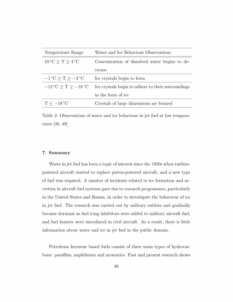
Temperature Range Water and Ice Behaviour Observations
10 ◦C ≥ T ≥ 4 ◦C Concentration of dissolved water begins to de-
crease
−1 ◦C ≥ T ≥ −3 ◦C Ice crystals begin to form
−12 ◦C ≥ T ≥ −18 ◦C Ice crystals begin to adhere to their surroundings
in the form of ice
T ≤ −18 ◦C Crystals of large dimensions are formed
Table 2: Observations of water and ice behaviour in jet fuel at low tempera-
tures [48, 49]
7. Summary
Water in jet fuel has been a topic of interest since the 1950s when turbine-
powered aircraft started to replace piston-powered aircraft, and a new type
of fuel was required. A number of incidents related to ice formation and ac-
cretion in aircraft fuel systems gave rise to research programmes, particularly
in the United States and Russia, in order to investigate the behaviour of ice
in jet fuel. The research was carried out by military entities and gradually
became dormant as fuel icing inhibitors were added to military aircraft fuel,
and fuel heaters were introduced in civil aircraft. As a result, there is little
information about water and ice in jet fuel in the public domain.
Petroleum kerosene based fuels consist of three main types of hydrocar-
bons: paraffins, naphthenes and aromatics. Past and present research shows
30
that the solubility of water in individual hydrocarbons becomes more promi-
nent in aromatics. The quantity of aromatic compounds in jet fuel is limited
to a maximum of 25% by volume. In practice, the aromatic content is in
the range 12% to 24%. Given the higher solubility of water in aromatic
compounds, it is believed that fuels with a higher concentration of aromatics
display a higher degree of hygroscopicity.
Synthetic kerosene fuels made from coal, natural gas, or other hydrocar-
bon feedstock have now been integrated, as a 50/50 blend with petroleum
derived jet fuels, into commercial aircraft with little or no modification to
current aircraft designs. The final blend must contain at least 8% of aro-
matics (by volume) in order to be used. The solubility of water in synthetic
kerosene is dependent on the conventional jet fuel used in the final blend.
Nonetheless, the hygroscopicity of synthetic kerosenes needs further research.
The hygroscopic nature of jet fuel refers to its ability to attract mois-
ture from the air or surroundings. This ability strongly depends on the fuel
temperature, with the Coordinated Research Council [2] reporting that for
a temperature drop of 10 ◦C in water-saturated fuel, 15 to 25 ppm of undis-
solved water comes out of solution. This is not a significant amount on its
own, but considering other sources of water contamination, fuel in a flying
aircraft may produce enough water that, when turned into ice, it may be of
concern for the safe operation of the aircraft fuel feeding system.
The type of nucleation of hygroscopic water as it slowly comes out of jet
31

fuel is an area of active interest in the research community. During experi-
ments, droplets can be seen in jet fuel at 14 ◦C, although other sources bring
this temperature down to 10 ◦C. The water droplets nucleate homogeneously
at temperatures lower than −35 ◦C.
If the fuel is agitated, there seems to be a shift in the temperature of
nucleation to temperatures just below the freezing point of water (0 ◦C). Ice
crystals and even snowflakes can be seen in the fuel at this stage, and it is
believed to be a case of heterogeneous nucleation.
A form of ice clusters that are prone to adhere to surfaces and to each
other has been labelled by the AAIB [1, 50] as “sticky ice”, and it is described
as soft and porous snow. Sticky ice in fuel is observed between temperatures
ranging from −12 ◦C to −18 ◦C. The ice tends to adhere to fuel lines, strain-
ers, and tank walls.
Hygroscopic or “shed-out” water is not a threat to aircraft fuel systems.
These systems have robustly designed scavenge systems that avoid the ac-
cumulation of water in remote corners in the aircraft tanks. There are also
a number of bypasses and fuel heaters to prevent ice from interrupting fuel
flow to the aircraft engines. Stringent QC measures are in place to deliver
dry fuel to the aircraft, as well as good maintenance procedures at airports
to sump any free water from aircraft tanks. However, the behaviour of water
in jet fuel, particularly at low temperatures, is an interesting phenomenon
that needs further understanding to reinforce design and certification require-
32

ments for future commercial aircraft.
References
[1] Report on the accident to Boeing 777-236ER, G-YMMM, at London
Heathrow Airport on 17 January 2008, Technical Report, Air Accident
Investigation Branch, Department of Transport (UK), 2010.
[2] Handbook of Aviation Fuel Properties (CRCReport No. 635). 3rd Edi-
tion, Technical Report, Coordinating Reseach Council, SAE, 2004.
[3] Defense Standard 91-91, Issue 7 - Turbine Fuel, Aviation Kerosine Type,
Jet A-1. NATO Code: F-35. Joint Service Designation: AVTUR, Tech-
nical Report, Ministry of Defence, 2011.
[4] ASTM D1655, Standard Specification for Aviation. Turbine Fuels, An-
nual Book of ASTM Standards (Section 05)., Technical Report, Ameri-
can Society of Testing and Materials (ASTM), 2009.
[5] JIG 1:2008 - Guidelines For Aviation Fuel Quality Control & Operat-
ing Procedures For Joint Into-plane Fuelling Services, Technical Report,
Joint Inspection Group Ltd., 2008.
[6] G. Hemighaus, T. Boval, J. Bacha, F. Barnes, M. Franklin, L. Gibbs,
N. Hogue, J. Jones, D. Lesnini, J. Lind, J. Morris, Aviation Fuels Tech-
nical Review, Technical Report, Chevron Coorporation, 2006.
[7] M. Smith, Aviation fuels, Foulis, 1970.
33

[8] M. D. Carpenter, J. I. Hetherington, L. Lao, C. Ramshaw, H. Yeung,
J. K.-W. Lam, S. Masters, S. Barley, in: 12th International Conference
on Stability, Handling and Use of Liquid Fuels.
[9] T. G. Kreutz, E. D. Larson, L. Guangjian, R. H. Williams, in: 25th
Annual International Pittsburgh Coal Conference, Pennsylvania, USA.
2008.
[10] M. R. Ladisch, Bioseparations Engineering: Principles, Practice and
Economics, Wiley, 2001.
[11] G. Hemighaus, T. Boval, C. Bosley, R. Organ, J. Bacha, J. Lind,
R. Brouette, T. Thompson, J. Lynch, J. Jones, Alternative Jet Fuels,
Technical Report, Chevron Coorporation, 2006.
[12] C. A. Moses, Comparative Evaluation of Semi-Synthetic Jet Fuels, Tech-
nical Report, U.S. Air Force Research Laboratories and Universal Tech-
noloies Corporation, 2008.
[13] ASTM D7566 (11a), Standard Specification for Aviation Turbine Fuel
Containing Synthesized Hydrocarbons, Technical Report, American So-
ciety of Testing and Materials (ASTM), 2011.
[14] D. Schroecker, E. Deurwaarder, P. Schild, J. Haavisto, L. Mikko,
J. Woodger, V. T, G. Muggen, J. Counsell, L. Hudson, P. Albano,
T. Komen, N. P., 2 million tons per year: A performing biofuels supply
chain for EU aviation, Technical Report, European Comission, 2011.
[15] IATA 2011 Report on Alternative Fuels, Technical Report, Internationa
Air Transport Association (IATA), 2011.
34

[16] E. M. Goodger, Transport fuels technology : mobility for the millen-
nium, Landfall Press, 2000.
[17] L. Meng, Water Management within Fuel Tanks, Master’s thesis, Cran-
field University, 2007.
[18] N. A. Ragozin, Jet propulsion fuels : translated from the Russian, New
York : Pergamon Press, 1961.
[19] Filter/Separator Vessel Manual, Velcon Filters LLC., Colorado Springs,
US., 2008.
[20] E. Goodger, R. Vere, Aviation Fuel Technology, Macmillan publishers
ltd., 1985.
[21] A. Oreshenkov, Chemistry and Technology of Fuels and Oils 40 (2004)
320–325.
[22] L. Lao, C. Ramshaw, H. Yeung, M. Carpenter, J. Hetherington, J. K.-
W. Lam, S. Masters, S. Barley, in: SAE Technical Paper 2011-01-2794,
2011.
[23] E. S. Dy, M. C. Jauco, F. B. Ventura, Chemistry, Science and Technology
III, Rex Printing Company, 1994.
[24] M. Oliveira, J. Coutinho, A. Queimada, Fluid Phase Equilibria 258 (1)
(2007) 58–66.
[25] C. Amovilli, F. Floris, Physical Chemistry Chemical Physics 5 (2)
(2003.) pp.363–368.
35

[26] I. Economou, C. Tsonopoulos, Chemical Engineering Science 52 (4)
(1997) pp.511–525.
[27] A. Klamt, Fluid Phase Equilibria 206 (1-2) (2003) pp.223–235.
[28] S. Nilsson, The Journal of Chemical Thermodynamics 18 (9) (1986)
pp.877–884.
[29] P. Ruelle, U. Kesselring, Journal of Solution Chemistry 25 (7) (1996)
pp.657–665.
[30] C. Tsonopoulos, Fluid Phase Equilibria 186 (1-2) (2001) pp.185–206.
[31] C. Tsonopoulos, Fluid Phase Equilibria 156 (1-2) (1999) pp.21–33.
[32] J. L. Atwood, F. Hamada, K. D. Robinson, G. W. Orr, R. L. Vincent,
Nature 349 (6311) (1991) 683–684.
[33] D. Feller, The Journal of Physical Chemistry A 103 (38) (1999) 7558–
7561.
[34] L. Chang, H. Gaohong, L. Xiangcun, P. Lin, D. Chunxu, G. Shuang,
X. Gongkui, Separation and Purification Technilogy 56 (2007) 175/183.
[35] J. W. Crellin, H. W. Carhart, The Behaviour of Water in Jet Fuels
and the Clogging of Micronic Filters at Low Temperatures, Technical
Report, Naval Research Lab, 1950.
[36] B. Englin, A. Plate, V. Tugolukov, M. Pryanishnikova, Chemistry and
Technology of Fuels and Oils 1 (1965) 722–726.
[37] G. Graziano, Biophysical Chemistry Volume 82 (1999) 69–79.
36
[38] J. A. Krynitsky, J. Crellin, H. Carhart, The Behavior of Water in Jet Fu-
els and the Clogging of Micronic Filters at Low Temperatures, Technical
Report, Naval Research Lab Washington DC, 1950.
[39] J. Morley, H. Adams, G. Jonke, R. Schilling, C. Stone, D. Harris,
G. Karel, Coordinating research council (CRC) aviation Handbook -
Fuels and Fuel Systems, Technical Report, Naval Air Systems, 1967.
[40] P. Debenedetti, S. Eugene, Physics Today 56 (2003) 40–46.
[41] G. Vali, Ice Nucleation Theory - A Tutorial, Technical Report, Na-
tional Center of Atmospheric Research - Advance Study Program
(NCAR/ASP), 1999.
[42] P. V. Hobbs, Ice Physics, Oxford : Clarendon Press, 1974.
[43] S. Shrikanth, Nature - International weekly Journal of Sciences 438
(2005) 746–747.
[44] B. J. Murray, S. L. Broadley, G. J. Morris, Supercooling of Water
Droplets in Jet Aviation Fuels - Fuel 90 (2011) 433–435.
[45] R. Shaw, A. Durant, M. Y., Heterogeneus Surface Crystallization Ob-
served in Undercooled Water. The Journal of Physical Chemistry B 109
(2005) 9865–9868.
[46] Y. Hayashi, A. Aoki, S. Adachi, K. Hori, ASME Journal of Heat Transfer
Vol. 99, No. 1 (1977) pp. 239–245.
[47] A. Luer, H. Beer, International Journal of Thermal Sciences Vol. 39 No.
1 (2000) pp. 85–95.
37

[48] SAE-International, AIR790 Considerations on Ice Formation in Aircraft
Fuel Systems, Technical Report, Ae-5 Aerospace Fuel, Oil And Oxidizer
Systems Committee, 2006.
[49] SAE-International, ARP1401 Aircraft Fuel System and Component Ic-
ing Test, Technical Report, Ae-5 Aerospace Fuel, Oil And Oxidizer Sys-
tems Committee, 2007.
[50] B. McDermid, Looking for ice, Unpublished, 2010. Lecture Notes, Cran-
field University.
38