beijin, china2nd rcm - iaea - crp on joint research using small tokamaks 1 highlights on egyptor...
TRANSCRIPT
Beijin, China2nd RCM - IAEA - CRP On Joint Research Using Small Tokamaks
1
Highlights on EGYPTOR Progress
By
H. Hegazy Plasma Physics Dept., NRC,
Atomic Energy Authority13759 Enshass, Egypt
Beijin, China2nd RCM - IAEA - CRP On Joint Research Using Small Tokamaks
2
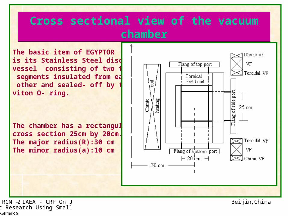
The basic item of EGYPTOR is its Stainless Steel discharge vessel consisting of two toroidal segments insulated from each other and sealed- off by two viton O- ring.
The chamber has a rectangular cross section 25cm by 20cm. The major radius(R):30 cmThe minor radius(a):10 cm
Cross sectional view of the vacuum chamber
Beijin, China2nd RCM - IAEA - CRP On Joint Research Using Small Tokamaks
3
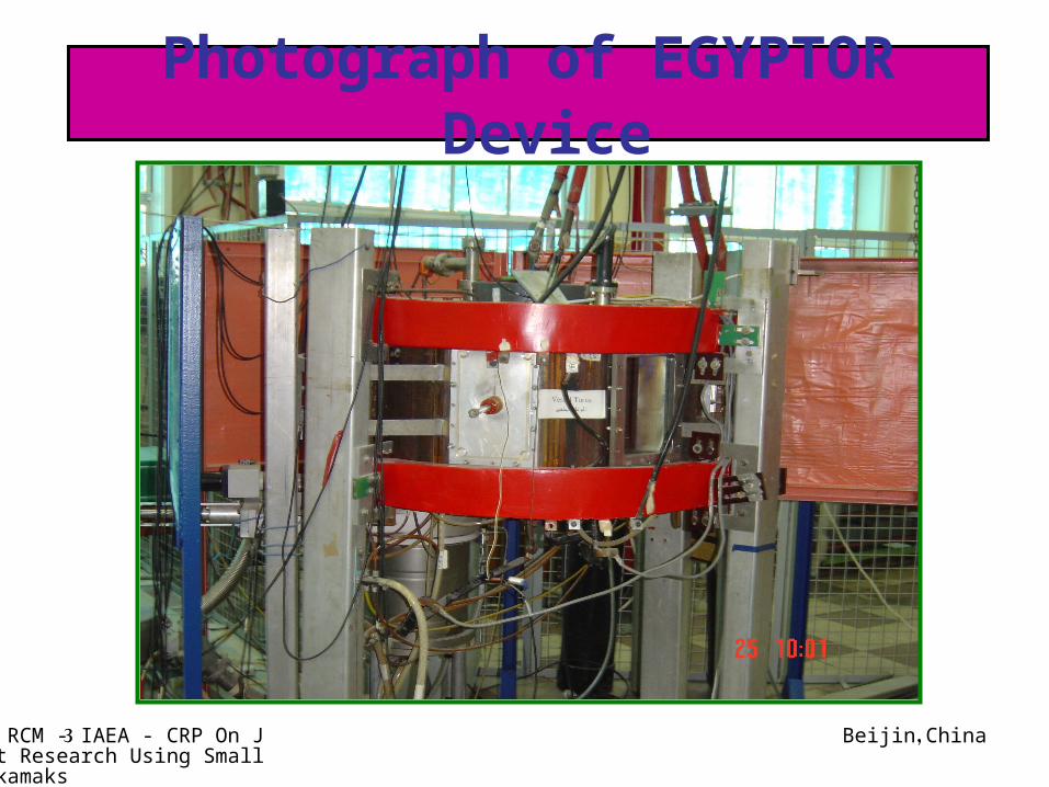
Photograph of EGYPTOR Device
Beijin, China2nd RCM - IAEA - CRP On Joint Research Using Small Tokamaks
4
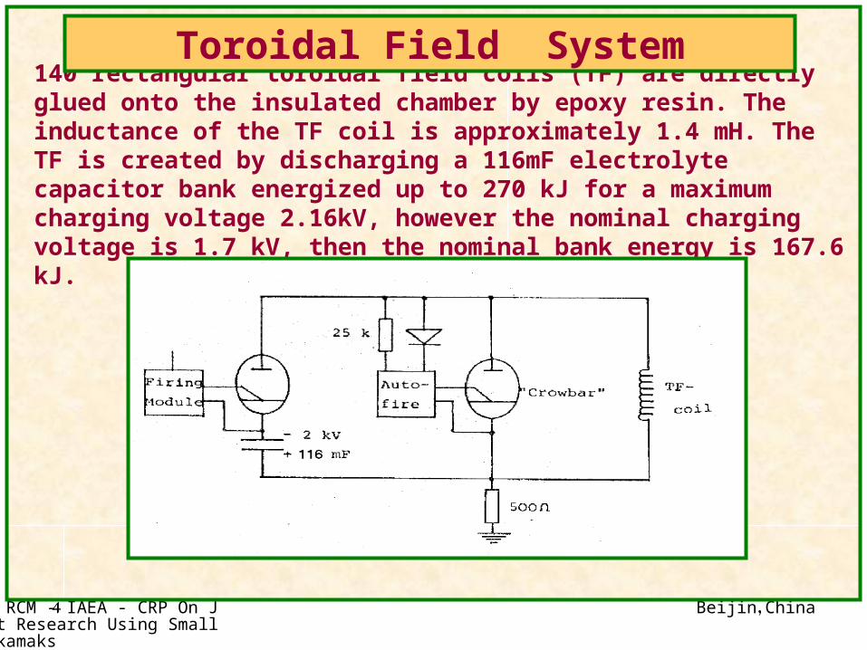
140 rectangular toroidal field coils (TF) are directly glued onto the insulated chamber by epoxy resin. The inductance of the TF coil is approximately 1.4 mH. The TF is created by discharging a 116mF electrolyte capacitor bank energized up to 270 kJ for a maximum charging voltage 2.16kV, however the nominal charging voltage is 1.7 kV, then the nominal bank energy is 167.6 kJ.
Toroidal Field System
Beijin, China2nd RCM - IAEA - CRP On Joint Research Using Small Tokamaks
5
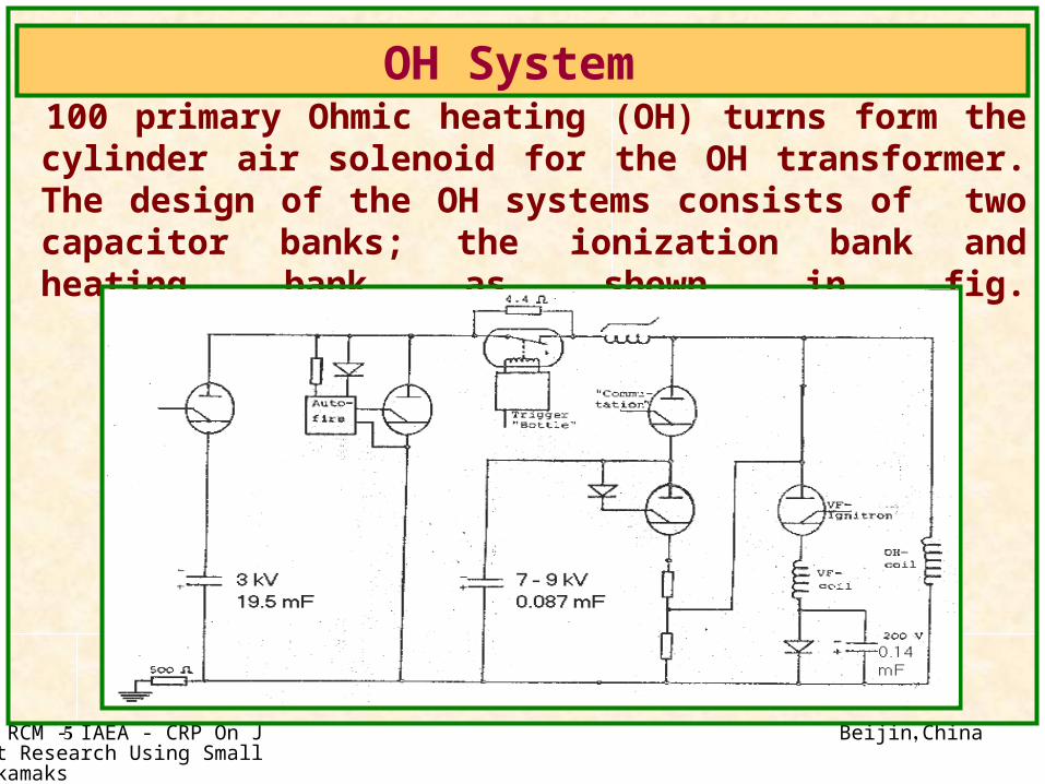
100 primary Ohmic heating (OH) turns form the cylinder air solenoid for the OH transformer. The design of the OH systems consists of two capacitor banks; the ionization bank and heating bank as shown in fig.
OH System
Beijin, China2nd RCM - IAEA - CRP On Joint Research Using Small Tokamaks
6
Plasma Investigations and Studying Obstacles Preventing the Prolongation of Plasma Discharge
and Plasma Current in EGYPTOR Tokamak
By
H. Hegazy Plasma Physics Department, NRC, EAEA,
13759 Inshass, Egyptand
Yu.V.Gott, M.M.DreminRussian Research Center
“Kurchatov Institute”, 123182 Moscow, Russian Federation
Beijin, China2nd RCM - IAEA - CRP On Joint Research Using Small Tokamaks
7
INTRODUCTIONThe main target of this experimental work is
to clarify the possibility to obtain the plasma discharge and to prolong its duration as
much as possible. There could exists several reasons as a possible
obstacles preventing obtaining this result:
*. improper operation of power supply system, *. the high level of stray magnetic fields,
*. the lack of equilibrium, *. the influence of MHD instabilities
*. The influence of impurities.
So we tried to analyze all this reasons

Beijin, China2nd RCM - IAEA - CRP On Joint Research Using Small Tokamaks
8
The duration of toroidal field pulse is long enough (30 ms with half battery), so the time interval with relatively small (20%) variation
of toroidal field is about 10 ms.
That’s why first of all we checked the operation of the Ohmic heating power
supply system.
Beijin, China2nd RCM - IAEA - CRP On Joint Research Using Small Tokamaks
9
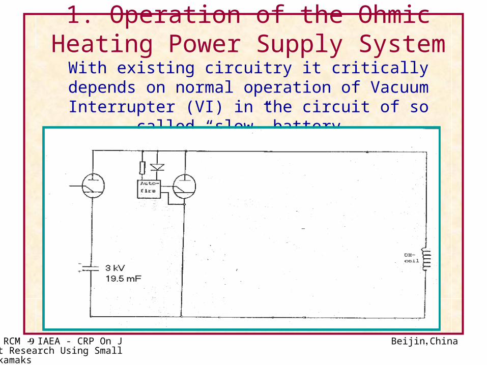
1. Operation of the Ohmic Heating Power Supply System
With existing circuitry it critically depends on normal operation of Vacuum Interrupter (VI) in the circuit of so
called “slow” battery.
Beijin, China2nd RCM - IAEA - CRP On Joint Research Using Small Tokamaks
10
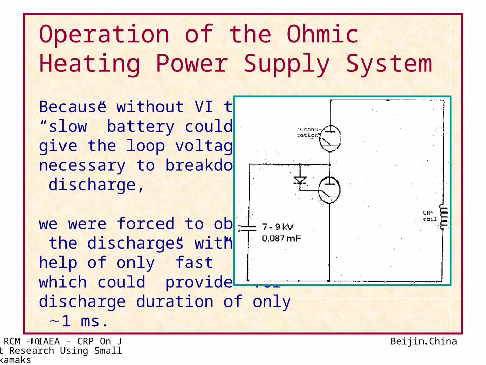
Operation of the Ohmic Heating Power Supply System
Because without VI the “slow” battery couldn’t give the loop voltage necessary to breakdown discharge, we were forced to obtain the discharges with the help of only ”fast” battery which could provide for discharge duration of only 1 ms.
Beijin, China2nd RCM - IAEA - CRP On Joint Research Using Small Tokamaks
11
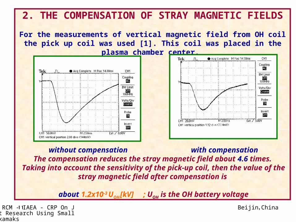
2. THE COMPENSATION OF STRAY MAGNETIC FIELDS
For the measurements of vertical magnetic field from OH coil the pick up coil was used [1]. This coil was placed in the plasma chamber center.
without compensation with compensationThe compensation reduces the stray magnetic field about 4.6 times.
Taking into account the sensitivity of the pick-up coil, then the value of the stray magnetic field after compensation is
about 1.2x10⁻³ UOH [kV] ; UOH is the OH battery voltage
Beijin, China2nd RCM - IAEA - CRP On Joint Research Using Small Tokamaks
12
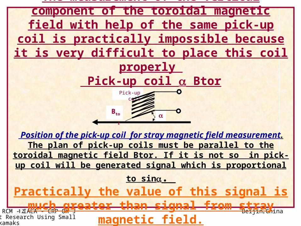
The measurement of the vertical component of the toroidal magnetic field with help of the same
pick-up coil is practically impossible because it is very difficult to place this coil properly
Pick-up coil Btor
Position of the pick-up coil for stray magnetic field measurement.The plan of pick-up coils must be parallel to the toroidal magnetic
field Btor. If it is not so in pick-up coil will be generated signal which
is proportional to sin. Practically the value of this signal is much greater
than signal from stray magnetic field.
Pick-up coil
Btor
Beijin, China2nd RCM - IAEA - CRP On Joint Research Using Small Tokamaks
13
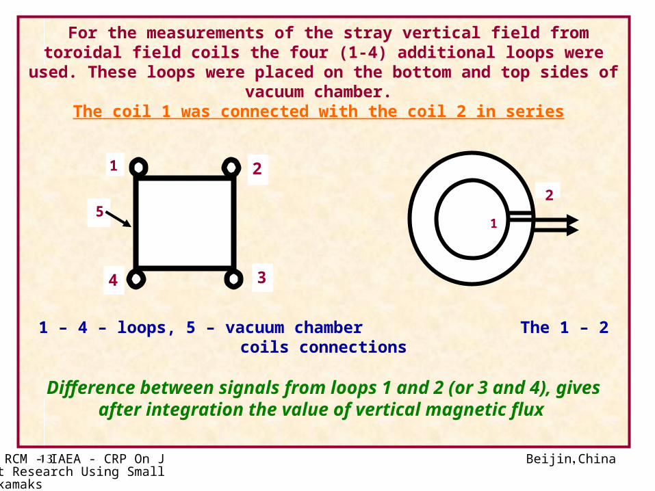
For the measurements of the stray vertical field from toroidal field coils the four (1-4) additional loops were used. These loops were placed on the
bottom and top sides of vacuum chamber. The coil 1 was connected with the coil 2 in series
1 – 4 – loops, 5 – vacuum chamber The 1 – 2 coils connections
Difference between signals from loops 1 and 2 (or 3 and 4), gives after integration the value of vertical magnetic flux
2
34
5
1
1
2
Beijin, China2nd RCM - IAEA - CRP On Joint Research Using Small Tokamaks
14
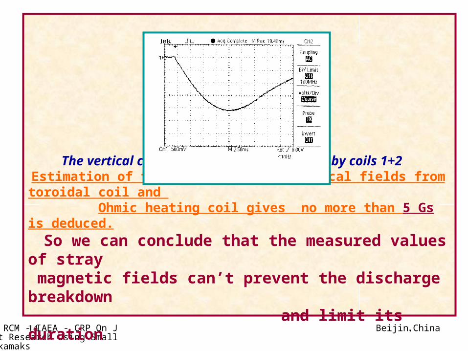
The vertical component of the TF measured by coils 1+2 Estimation of the value of stray vertical fields from toroidal coil and
Ohmic heating coil gives no more than 5 Gs is deduced.
So we can conclude that the measured values of stray magnetic fields can’t prevent the discharge breakdown and limit its duration

Beijin, China2nd RCM - IAEA - CRP On Joint Research Using Small Tokamaks
15
3. Investigation of the plasma column equilibriumFor these estimations we use the pair of Mirnov probes (outer and inner) installed in vacuum chamber. The precise evaluation of plasma position in the chamber envisage the calibrated measurements of poloidal magnetic field and average vertical magnetic field in accordance with formulae
where is horizontal displacement of plasma column, a is minor plasma radius, R is major plasma radius, b is minor radius on which the Mirnov probes are placed, J is the plasma current, B+ and B - are the aziumuthal magnetic field measured by outer and inner Mirnov probes accordingly, B - averaged transverse magnetic field measured by loops 1-2 or 3-4.
2
2
2
2
2
2
2
2
112
11
41
2
1ln
2 b
aB
b
aR
bB
R
bB
J
cb
b
a
a
b
b
a
R
b
b
Beijin, China2nd RCM - IAEA - CRP On Joint Research Using Small Tokamaks
16
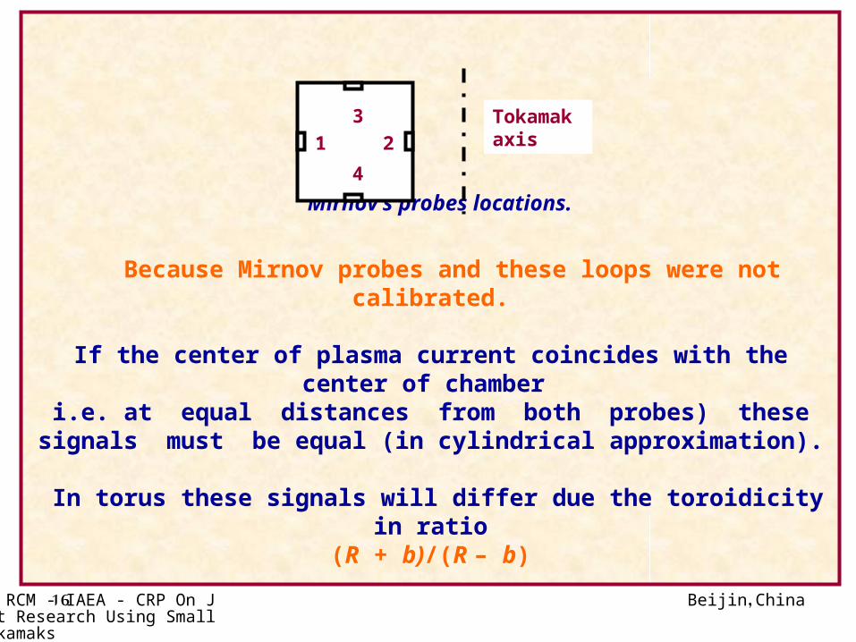
Mirnov’s probes locations.
Because Mirnov probes and these loops were not calibrated.
If the center of plasma current coincides with the center of chamber i.e. at equal distances from both probes) these signals must be
equal (in cylindrical approximation).
In torus these signals will differ due the toroidicity in ratio (R + b)/(R – b)
1 2
3
4
Tokamak axis
Beijin, China2nd RCM - IAEA - CRP On Joint Research Using Small Tokamaks
17
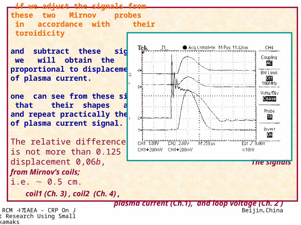
if we adjust the signals from these two Mirnov probes in accordance with their toroidicity
and subtract these signals we will obtain the signal proportional to displacement of plasma current.
one can see from these signals that their shapes are similar and repeat practically the shape of plasma current signal.
The relative differenceis not more than 0.125displacement 0,06b, The signals from Mirnov’s coils;
i.e. 0.5 cm. coil1 (Ch. 3) , coil2 (Ch. 4), plasma current (Ch.1), and loop voltage (Ch. 2 )
Beijin, China2nd RCM - IAEA - CRP On Joint Research Using Small Tokamaks
18
So we can conclude that the plasma equilibrium in these discharges is good enough and in any case couldn’t be
the reason for their short duration or small plasma current value.
Beijin, China2nd RCM - IAEA - CRP On Joint Research Using Small Tokamaks
19
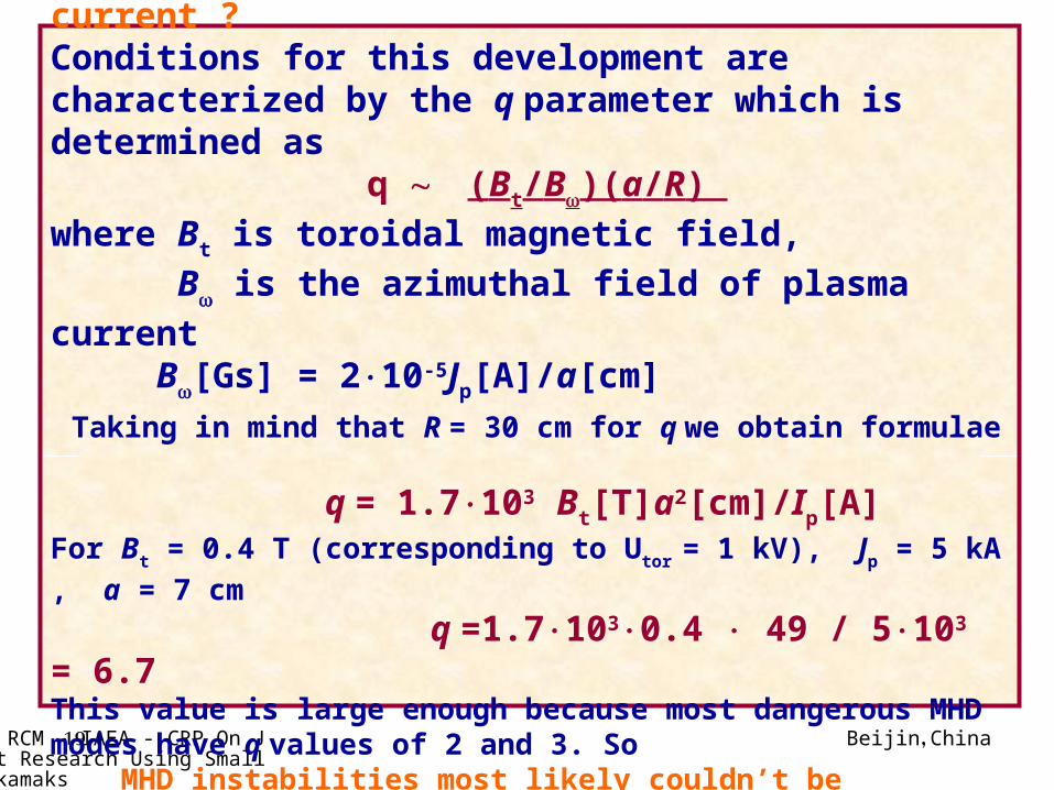
4. MHD instabilitiesAre MHD instabilities responsible for short
duration and small amplitude of plasma current ?Conditions for this development are characterized by the q parameter which is determined as
q (Bt/B)(a/R)
where Bt is toroidal magnetic field,
B is the azimuthal field of plasma current
B[Gs] = 210-5Jp[A]/a[cm]
Taking in mind that R = 30 cm for q we obtain formulae
q = 1.7103 Bt[T]a2[cm]/Ip[A]For Bt = 0.4 T (corresponding to Utor = 1 kV), Jp = 5 kA , a = 7 cm
q =1.71030.4 49 / 5103 = 6.7 This value is large enough because most dangerous MHD modes have q values of 2 and 3. So MHD instabilities most likely couldn’t be responsible for short
duration and small amplitude of plasma current.
Beijin, China2nd RCM - IAEA - CRP On Joint Research Using Small Tokamaks
20
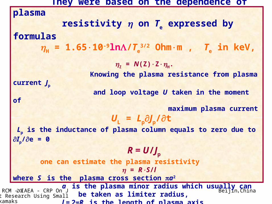
5. Estimations of plasma electron temperature Te
They were based on the dependence of plasma resistivity on Te expressed by formulas
H = 1.6510-9ln/Te3/2 Ohmm , Te in keV,
Z = N(Z)ZH.
Knowing the plasma resistance from plasma current Jp
and loop voltage U taken in the moment of maximum plasma current
UL = LpJp/t Lp is the inductance of plasma column equals to zero due to Ip/е = 0
R = U/Jp
one can estimate the plasma resistivity = RS/l where S is the plasma cross section a2 a is the plasma minor radius which usually can be taken as limiter radius, l = 2R is the length of plasma axis
( R =0.3 m is the plasma major radius).
Beijin, China2nd RCM - IAEA - CRP On Joint Research Using Small Tokamaks
21
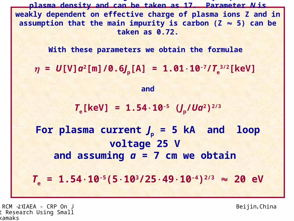
The value of Coulomb logarithm ln is weakly dependent on plasma density and can be taken as 17. Parameter N is weakly dependent on effective
charge of plasma ions Z and in assumption that the main impurity is carbon (Z 5) can be taken as 0.72.
With these parameters we obtain the formulae
= U[V]a2[m]/0.6Jp[A] = 1.0110-7/Te3/2[keV]
and
Te[keV] = 1.5410-5 (Jp/Ua2)2/3
For plasma current Jp = 5 kA and loop voltage 25 V
and assuming a = 7 cm we obtain
Te = 1.5410-5(5103/254910-4)2/3 20 eV
Beijin, China2nd RCM - IAEA - CRP On Joint Research Using Small Tokamaks
22
This value is very close to so called “radiation limit” which was observed in first Tokamaks and is associated
with high level of impurities. So as an obvious way to improve the plasma
performance in EGYPTOR tokamak we consider the decreasing of the level of plasma
impurities using cleaning discharge system
( Dc Glow discharge, as the first step &
50 Hz Taylor discharge as the second step if it is still necessary)

Beijin, China2nd RCM - IAEA - CRP On Joint Research Using Small Tokamaks
23
Glow Discharge in EGYPTOR
Smooth operation of 600V, 0.6 A DC Glow Discharge is in operation and special study of the impurity contents using Emission Spectroscopy will be
part of the aim of the next year.
Beijin, China2nd RCM - IAEA - CRP On Joint Research Using Small Tokamaks
24
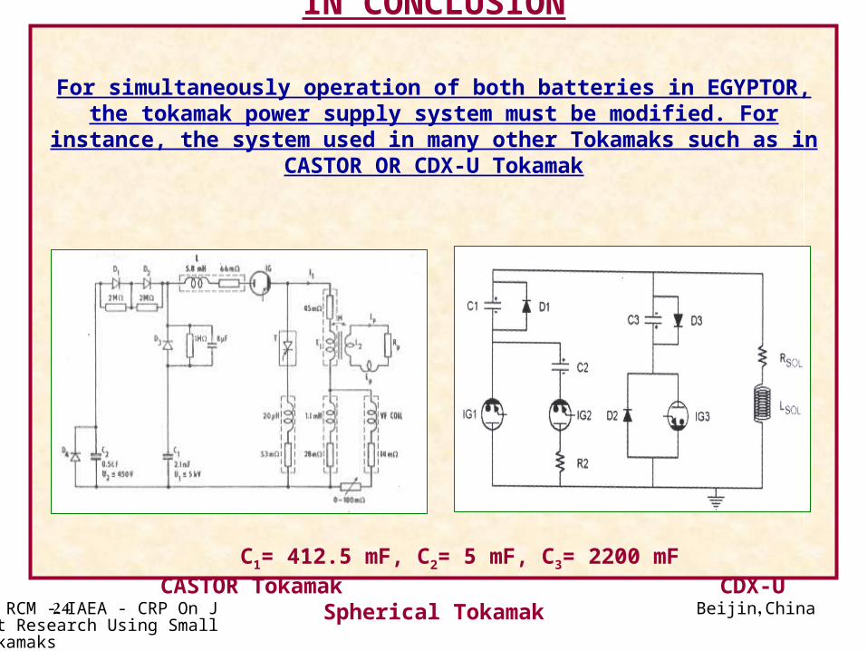
IN CONCLUSION
For simultaneously operation of both batteries in EGYPTOR, the tokamak power supply system must be modified. For instance, the system used in
many other Tokamaks such as in CASTOR OR CDX-U Tokamak
C1= 412.5 mF, C2= 5 mF, C3= 2200 mF
CASTOR Tokamak CDX-U Spherical Tokamak
Beijin, China2nd RCM - IAEA - CRP On Joint Research Using Small Tokamaks
25
Modification of the Toroidal Current Generation Scheme in EGYPTOR
Tokamak
By
H. Hegazy
Plasma Physics Dept., NRC, Cairo, EGYPT
And
K. Dyabilin
Institute for High Temperatures
Moscow, Russia
Beijin, China2nd RCM - IAEA - CRP On Joint Research Using Small Tokamaks
26
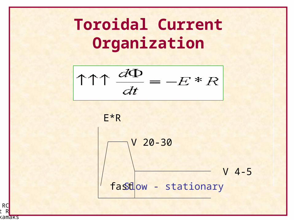
Toroidal Current Organization
E*R
20-30 V
4-5 V
fast Slow - stationary
Beijin, China2nd RCM - IAEA - CRP On Joint Research Using Small Tokamaks
27
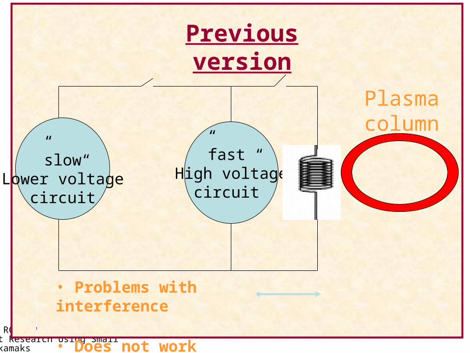
Plasma column
“slow”Lower voltage
circuit
“fast”High voltage
circuit
Previous version
• Problems with interference
• Does not work
Beijin, China2nd RCM - IAEA - CRP On Joint Research Using Small Tokamaks
28
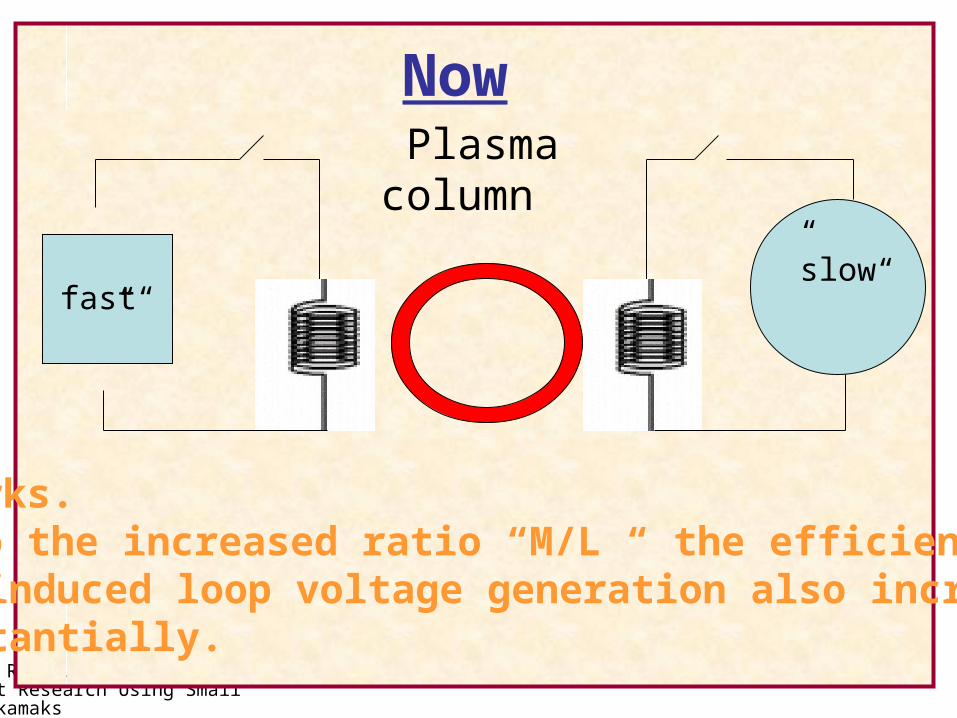
Now
“fast”
Plasma column
“slow”
It works.Due to the increased ratio “M/L “ the efficiency of the induced loop voltage generation also increased substantially.

Beijin, China2nd RCM - IAEA - CRP On Joint Research Using Small Tokamaks
29
“fast ”circuit “slow”
circuit
chamber
Scheme on the Tokamak

Beijin, China2nd RCM - IAEA - CRP On Joint Research Using Small Tokamaks
30
T.F. = 400 V
OHF = 4 KV
OHS = 400 V
Beijin, China2nd RCM - IAEA - CRP On Joint Research Using Small Tokamaks
31
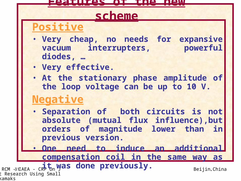
Features of the new scheme
Positive• Very cheap, no needs for expansive vacuum
interrupters, powerful diodes, …• Very effective.• At the stationary phase amplitude of the loop
voltage can be up to 10 V.
Negative• Separation of both circuits is not absolute (mutual
flux influence),but orders of magnitude lower than in previous version.
• One need to induce an additional compensation coil in the same way as it was done previously.
Beijin, China2nd RCM - IAEA - CRP On Joint Research Using Small Tokamaks
32
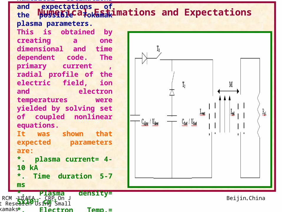
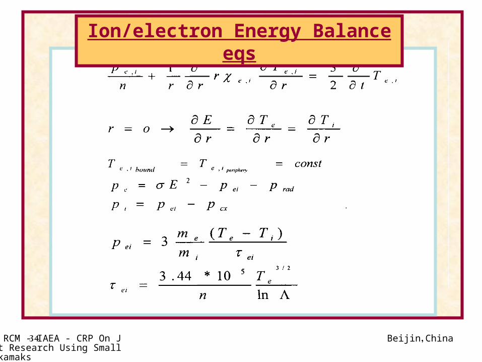
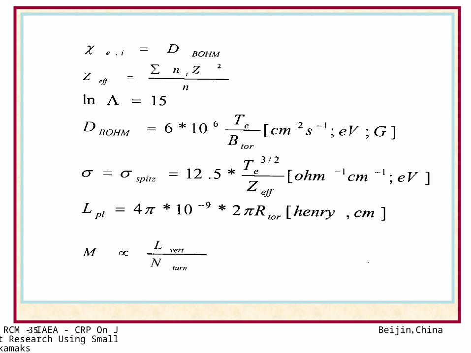
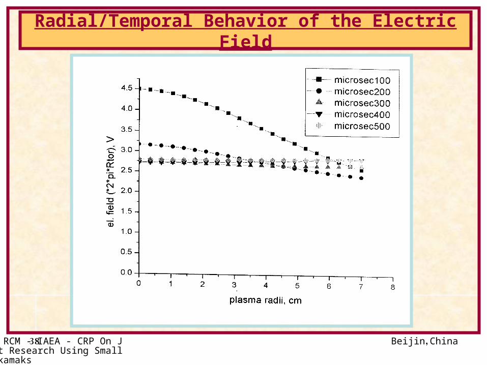
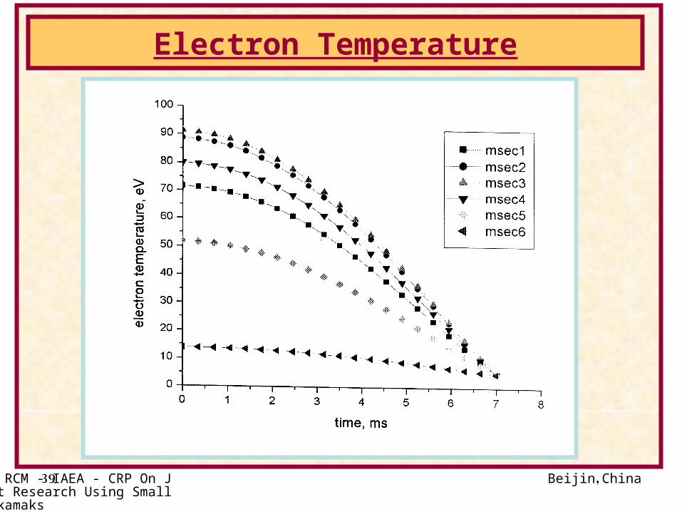
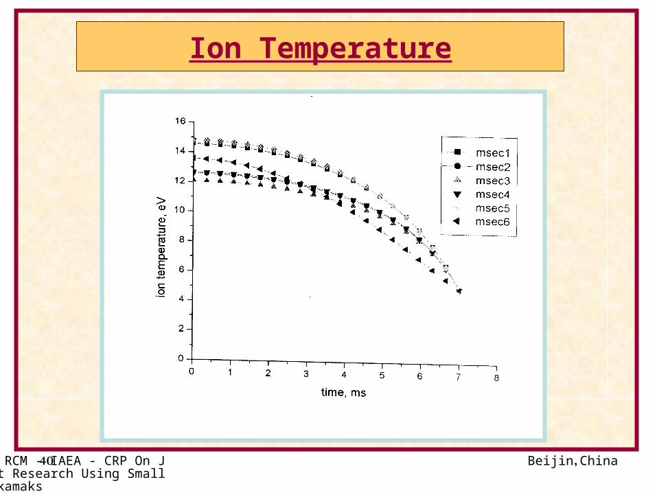
Numerical Estimations and Expectations
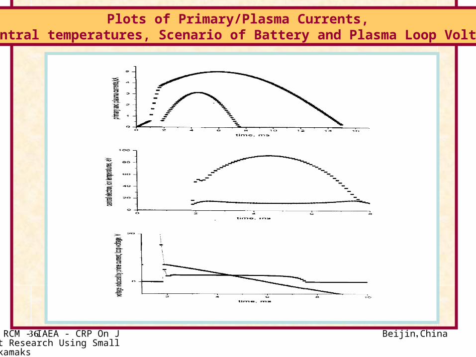
Part of the activity was devoted few numerical estimations and expectations of the possible Tokamak plasma parameters.This is obtained by creating a one dimensional and time dependent code. The primary current , radial profile of the electric field, ion and electron temperatures were yielded by solving set of coupled nonlinear equations.It was shown that expected parameters are:*. plasma current= 4-10 kA*. Time duration 5-7 ms*. Plasma density= 5x1012 cm-3
*. Electron Temp.= 100-200 eV*. Ion Temp.= 15 eV
Beijin, China2nd RCM - IAEA - CRP On Joint Research Using Small Tokamaks
33
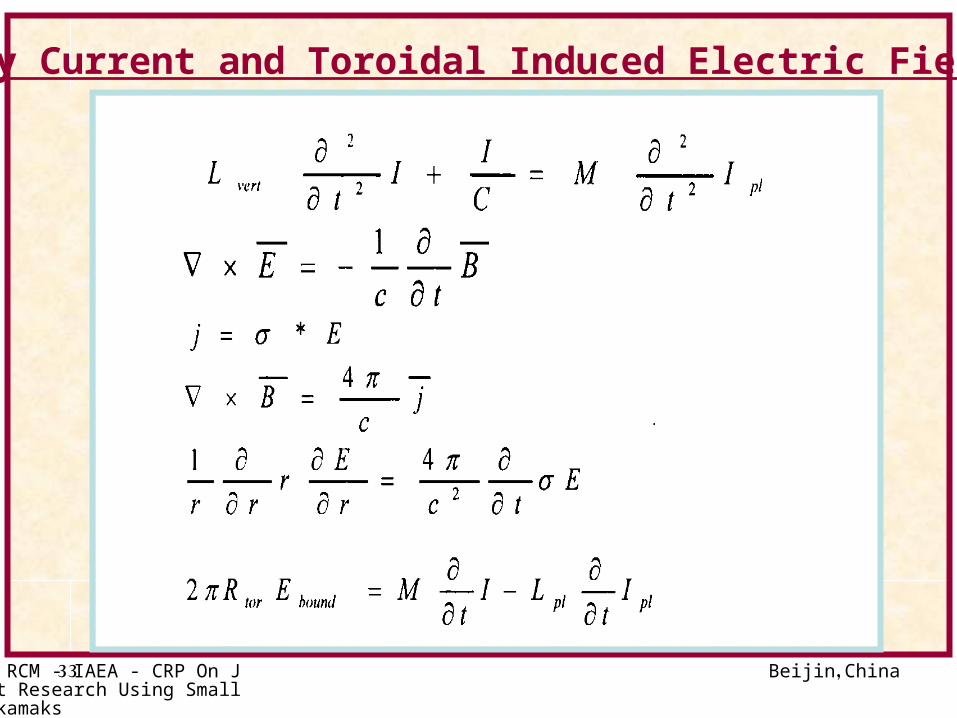
Primary Current and Toroidal Induced Electric Field eqs
Beijin, China2nd RCM - IAEA - CRP On Joint Research Using Small Tokamaks
34
Ion/electron Energy Balance eqs
Beijin, China2nd RCM - IAEA - CRP On Joint Research Using Small Tokamaks
35
Beijin, China2nd RCM - IAEA - CRP On Joint Research Using Small Tokamaks
36
Plots of Primary/Plasma Currents, Central temperatures, Scenario of Battery and Plasma Loop Voltage
Beijin, China2nd RCM - IAEA - CRP On Joint Research Using Small Tokamaks
37
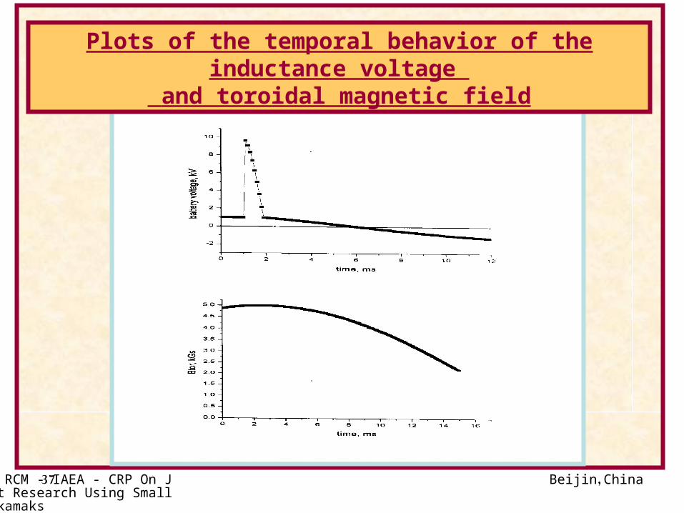
Plots of the temporal behavior of the inductance voltage and toroidal magnetic field
Beijin, China2nd RCM - IAEA - CRP On Joint Research Using Small Tokamaks
38
Radial/Temporal Behavior of the Electric Field
Beijin, China2nd RCM - IAEA - CRP On Joint Research Using Small Tokamaks
39
Electron Temperature
Beijin, China2nd RCM - IAEA - CRP On Joint Research Using Small Tokamaks
40
Ion Temperature
Beijin, China2nd RCM - IAEA - CRP On Joint Research Using Small Tokamaks
41
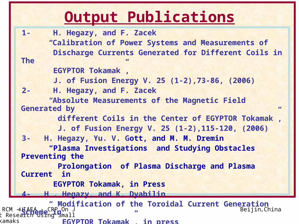
Output Publications1- H. Hegazy, and F. Zacek “Calibration of Power Systems and Measurements of Discharge Currents Generated for Different Coils in The EGYPTOR Tokamak”, J. of Fusion Energy V. 25 (1-2),73-86, (2006)2- H. Hegazy, and F. Zacek “Absolute Measurements of the Magnetic Field Generated by different Coils in the Center of EGYPTOR Tokamak”, J. of Fusion Energy V. 25 (1-2),115-120, (2006)3- H. Hegazy, Yu. V. Gott, and M. M. Dremin “Plasma Investigations and Studying Obstacles Preventing the Prolongation of Plasma Discharge and Plasma Current in EGYPTOR Tokamak, in Press4- H . Hegazy, and K. Dyabilin “ Modification of the Toroidal Current Generation Scheme in EGYPTOR Tokamak”, in press

Beijin, China2nd RCM - IAEA - CRP On Joint Research Using Small Tokamaks
42
Expected activities for the Next yearExperimental Activities:
Improvement of Plasma discharge and Current Ramp up
Wall Conditioning of EGYPTOR vessel.
Study of impurities emitted during the cleaning discharge By
Emission Spectroscopy.
Measurements of Electron Temperature in EGYPTOR Tokamak
using Langmuir probe .Development of Control System for EGYPTOR based on Data
Acquisition Theoretical Activities:
Study the effect of External Electric Field on Drift of the Plasma
Across the Magnetic Field in Tokamak
Study of Surface waves propagation along a Toroidal Plasma
Column.

Beijin, China2nd RCM - IAEA - CRP On Joint Research Using Small Tokamaks
43