belize electricity call us at: limited 0-800-bel … installation manual 2006.pdf · service...
TRANSCRIPT

BELIZE ELECTRICITY LIMITED
SERVICE INSTALLATION MANUAL
BELIZE ELECTRICITY LIMITED BELIZE CITY
BELIZE CENTRAL AMERICA
REVISION DATE: AUGUST 2006
CALL US AT: 0-800-BEL-CARE (0-800-235-2273), if you need additional information about your service requirements or need to make an appointment with a Company representative. Our 0-800-BEL-CARE (0-800-235-2273) Toll Free Number may be busy whenever there is an electricity problem and other customers are calling. Please be patient! We will take your call as soon as the line is free.
1

Table of Contents
Standard Installation Requirements……………….. 3 How to contact BEL………………………………. 4 1.0 Definitions…………………………………..… 5 2.0 Supply Frequency and Voltage……………..… 7 2.1 Customer Wiring………………………… 9 2.2 Important Notes on Loads………………….. 12 2.3 Changes in Customer Requirements………….. 13 2.4 Discontinuation or Refusal of Service……….. 13 2.5 Distribution Line Work………………………. 14 3.0 Clearance…………………………………… 16 4.0 Service Installation Requirements………….… 22 4.1 Three Wire Installation……………………….. 22 4.2 Three Phase Low Voltage Services…………... 28 4.3 Overhead Pole mount Transformer…………… 28 4.4 Pad mount Transformer Installation…………... 29 4.5 Pad mount Transformer Installation Details….. 30 5.0 Metering…………………………………….… 32 5.1 Meter Sockets…………………………………. 32 5.2 Single Meter Installation……………………… 33 5.3 Metering Current Transformers (CTs)……….. 35 5.4 Metering High Tension Services……………... 36 6.0 BEL Inspections….…………………………… 37 6.1 BEL Inspection Details…………………..…… 38 7.0 Protect Your Equipment……………………… 40 7.1 Protection For Electronic Equipment………… 40 7.2 Protection of Motorized Equipment ………..… 41 Drawings…………………………………… 42-64
BELIZE ELECTRICITY LIMITED
STANDARD INSTALLATION REQUIREMENTS
BELIZE ELECTRICITY LIMITED 2 ½ Miles Northern Highway BELIZE CITY, BELIZE, C.A.
IMPORTANT SAFETY INSTRUCTIONS
• All electrical equipment must be wired in
accordance with the National Electrical Code • Proper grounding is required to ensure
personal safety • Use approved connectors for all electrical
connections • ALL work should be done by competent
licensed wiremen. WARNING: Disconnect power from the source before installing, modifying or servicing. Wherever personnel or equipment safety is concerned, do not rely exclusively on power monitoring devices. It is safest to always verify the status and safety of all electrical power equipment before operating, energizing, or working with them.
2 3

4
This SERVICE INSTALLATION MANUAL has been prepared with the following objectives: • To acquaint licensed wiremen, contractors, consultants and
other technical personnel involved in the installation of electrical services with the standards and procedures of the Belize Electricity Limited (BEL).
• To reduce delays in connecting new services through a better
understanding of our procedures and standards. • To reduce costs to both customers and the company by
improving efficiency when installing new services. • To promote closer cooperation between BEL and those
involved in the installation of electrical services. HOW TO CONTACT BEL Address: Belize Electricity Limited
2 ½ Miles Northern Highway Belize City
BELIZE Telephone: 0-800-BEL-CARE (0-800-235-2273) 501-227-0954 Telefax: 501-223-0891
1.0 DEFINITIONS BEL Belize Electricity Limited Company Belize Electricity Limited CTs Current Transformers used in the metering of
services in excess of 200 amps. Customer User of BEL’s electric service or an authorized
representative (architect, electric contractor, electrician, etc.)
Demand The rate at which electric energy in KW, KVA or
KVAR is metered per time interval (i.e. instantaneous, 15 minute, 30 minute or 1 hour). BEL demand meters record the highest kVA demand in any 15-minute period during the billing period.
HV High Voltage (HV) is BEL’s system voltage
before transformation. HV Metering A unit which consists of Current Transformers Unit (CTs) and Potential Transformers (PTs) for the
purpose of metering customers who are provided with a high voltage supply.
LV Low Voltage (LV) is BEL’s system voltage after
transformation.
5

Meter Socket A meter-mounting device installed for the purpose of accepting BEL’s electric revenue meter. Network A 120/208 Volt, three wire service Supply obtained from the two-phase wires and a neutral of
a three phase, four wire, wye system. PUC The Public Utilities Commission. In the absence of
established construction regulations, the PUC has responsibility to regulate the electric construction sector.
Service Drop The overhead service conductor between BEL’s
secondary conductors and the point of attachment to the Customer’s weather heads.
Service Point The point of termination of BEL’s supply
conductors and the connection to the customer’s service conductors.
UL Underwriters Laboratories is an independent entity
that tests and certifies an electrical equipment conformance to accepted standards.
6
2.0 SUPPLY FREQUENCY AND
VOLTAGE The company supplies electricity at 60 Hertz (cycles per second). Various supply options/service types are available to customers depending on the customer’s requirements, and the distribution network in the area. Single Phase/Three Wire Services The Company provides the following three wire services.
• 120/208 Volts, 3 wire, network (see Figure 1) • 120/240 Volt, 3 wire, single phase. (See Figure 2) The 127/220 Volt service is now considered a BEL nonstandard voltage and is to be discontinued. Customers requiring single phase, 3 wire service will normally have an inspection certificate for 120/240 Volt supply. However, there may be a few instances where the low-voltage supply is provided from a network system an existing customers receive a 120/208 Volt supply. The electrician or electrical contractor should check with the Company if in doubt then advise the customer accordingly.
7
Three Phase Four Wire, Services The following three phase four wires services are provided by the Company.
• 120/208 Volt, 3 phase, 4 wire (See Figure 4 )
• 120/240 Volt, 3 phase-Open Delta, 4 wire (See Figure 3)
• 277/480 Volt, 3 phase, 4 wire (Figure 5)
Please refer to Section 4.2 - 4.4 of this booklet, for information that deals with Three Phase Installations to check the conditions that apply to each type of service.
Important 1. In every case, the Customer should consult with
the Company to determine the characteristics of the service to be supplied before procuring any equipment for new or existing installations.
2. The Company will endeavor at all times to provide
a continuous and adequate electricity supply. However, it cannot guarantee the service as to the continuity, freedom from voltage and frequency variations, and will not be responsible for damage to the customer’s equipment resulting from failure or imperfection of service. The customer is therefore advised to install suitable protective and surge suppression equipment to protect his/her equipment.
2.1. CUSTOMER WIRING As a rule, only one service connection is permitted to a building. It is usually in the customer’s best interest to make adequate provision in the initial wiring of the premises for future use of appliances and equipment. Proper planning of the electrical installation is essential. Customers’ wiring and equipment should conform with the following: a) The Company’s Service Installation Requirements. (See
Section 4.0) b) Internal wiring regulations covered by the National
Electric Code of the National Fire Protection Association (NFPA).
c) Other statutory regulations established under the Laws of
Belize.
1. In order to minimize voltage fluctuations and to improve efficiency, circuits supplying major appliances and power points should be separated from the lighting circuits.
2. In view of the ever increasing use of electrical service in the home, office, store and factory, it is strongly recommended that spare capacity of at least 50% should be provided whenever new switches, panels, feeders and circuits are installed. In cases of commercial and industrial applications, transformer sizes should be substantiated by accurate load schedules. The final choice of size of transformer to be installed is left to the discretion of the utility.
3. Load mains of adequate size should be provided from the
main circuit breaker to the meter position. (See Section 4.0) 8 9

4. The manner in which the customer connects single phase
loads with three phase service is critical. On 120/208 Volt, “wye” services, all single-phase loads should be split evenly among the three phases. On 120/240 Volts, three phase “open delta” services, all single phase load shall be connected to the 120 Volt to ground legs. No single-phase load shall be connected to the “high” leg. Connections made otherwise may result in high voltage or single-phase condition increasing the possibility of damage to the customer’s equipment. Note: The 208 Volts to ground leg (“high” phase) should be located to the extreme right on meter base and main disconnect and shall be clearly and permanently marked with ORANGE tape or paint at all visible points.
5. The disconnecting means required for every set of service-
entrance conductors must be located at a readily accessible point nearest to the point at which the service conductors enter the building, on either the inside or the outside of the building (Figure 6). The service disconnect switch (or circuit breaker) is generally placed on the inside of the building as near as possible to the point at which the conductors come in. Service cable may not run within the building more than 18 inches from its point of entry to the point at which it enters the disconnect as per NEC article 230-70. Over current protection must be provided for all line conductors right at the point at which they emerge from the wall into the building and must be capable of isolating all line conductors.
Switches or circuit breakers used for service-entrance disconnecting means must be approved for use as service equipment. This rule is meant to require that the switch be
listed and labeled by the UL as suitable for service entrance. The customer or his electrician is advised to check the manufacturer’s catalogs on this. Service-entrance conductors must be equipped with a readily accessible means of disconnecting the conductors from their source of supply. The disconnect means for each set of service entrance conductors permitted by NEC Sec. 230-2 and 230-40 may consist of not more than six switches or six circuit breakers, in a common enclosure or grouped individual enclosures, located either inside or outside the building wall as close as possible to the point at which the conductors enter the building. Note: In addition to NEC SEC 230-2 and 230-40, the PUC requires the installation of a main disconnect for all service entrances regardless of number of circuit interruption devices located in a common enclosure. Figure 7 shows the basic application of that rule to a single set of service entrance conductor.
6. The Company is not responsible for defects in customer’s wiring or for any damage that may result from such defects. If the customer discovers any defects in any part of the installation, steps should be taken to rectify the defects. The customer provides the socket base and the Company does not accept any liability for damage that may arise from a defect in the socket base.
7. BEL will only entertain request for single phase and 3-
phase service as per the standard service entrance sizes identified on Table 3 on Page 24. All new service entrances should be constructed with standard material sizes and conductor color-coding described in this table.
10 11

2.2 IMPORTANT NOTES ON LOADS
1. Motors, motor starting equipment and other apparatus
such as welders and X-ray machines, particularly with respect to in-rush current, should be installed and connected such as not to impair the quality of service rendered by the Company to its customers.
2. Motors up to 1 h.p. can be supplied at 120 volts single
phase. 3. Single phase motors of over 1 h.p. and up to 5 h.p. should
be 240, 208 or 220 Volts. Customers should consult with the Company to determine which voltages are available in the area.
4. Motors of over 5 h.p. must be 3 phase. These should be
fitted with reduced voltage starting if the customer is fed directly from the low-voltage distribution mains.
5. Single-phase miscellaneous appliances supplied from 3 or
4 wire services should be so connected that the operating current unbalance between phases will be less than 10%.
6. Commercial and industrial loads in which a large portion
of the load consists of fluorescent and other gaseous discharge lighting equipment of inherently poor power factor should aim at correcting this value to at least 0.85 before being connected to the system.
2.3 CHANGES IN CUSTOMERS REQUIREMENTS The capacity of the service provided by the Company is designed to meet the capacity requirements of the existing installation at the time of connection. If a customer’s actual demand is substantially less than the rated capacity of the installed devices, BEL will install new equipment to meet this reduced demand. Likewise, customers should give ample notice of their intention to change electrical equipment that may require an increased capacity. BEL shall attempt to provide adequate facilities that will suit the demand. In cases where a customer is considering carrying out alterations to the existing installation, prior notice of such intent shall be given to BEL. Service connections, meters or metering equipment shall not be removed or relocated unless authorized by BEL.
2.4 DISCONTINUTATION OR REFUSAL OF SERVICE
BEL may refuse or disconnect service for certain reasons, several of which are listed below: 1. Non-payment of bills for electric service. 2. Refusal or failure to make a deposit when requested. 3. Failure to rectify a deficiency or defect in the customer’s
wiring or other facilities after receiving notice from BEL that such condition exists.
12 13

4. Unauthorized use of electric energy including tampering
with meters and metering equipment as well as current diversion.
5. Operation of equipment, which causes voltage flicker or
objectionable service to other customers. 6. Without notice in cases where the customer has removed
or relocated meters and/or metering equipment without the proper authorization of BEL.
7. Without notice in the event a hazardous condition is found
by BEL.
2.5 DISTRIBUTION LINE WORK The following services will normally require additional line work. Company personnel may need to visit the proposed site to prepare an estimate for the cost of providing service.
• Single phase loads in excess of 100 Amps.
• Three phase loads.
In some instances smaller single-phase services may also require line extension work to be carried out. Estimates need to be prepared and these take time. During the preparation of an estimate, delays may occur which can ultimately delay the entire installation. (e.g. Poles have to be planted on another person’s property and permission needs to be sought or material orders may be delayed). In order to avoid delays in connection, the Company should be contacted in the early planning stages. In the case of large commercial or industrial customers, it may be necessary to order equipment (e.g. transformers) which may take up to six months to obtain. Persons considering building or acquiring homes on land where electricity supply lines do not presently exist are advised to contact the Company during the planning stages to obtain cost estimates of electric service. Land developers should present authenticated survey plans of their intended development to the Company in adequate time to allow for the electrical layout to be designed and estimated. Trees in the area which would interfere with the Company’s proposed overhead electric facilities may need to be trimmed or in some cases removed by the customer or developer as required by the Company. BEL will not install power lines until all site work has been completed by the developer. This site work will include physical surveys, roadways, and drainage works. The developer is also encouraged to coordinate works in conjunction with other utilities.
14 15

3.0 CLEARANCES It is necessary that buildings and other facilities be kept away from BEL conductors. Open conductors must be protected from contact to persons by keeping them high enough above ground or above other positions where people might be standing and they must not present an obstruction to vehicle passage or other activities below the lines. The clearances apply to open supply conductors, triplex conductors and quadruplex conductors. In accordance with NEC rule 225-26, outdoor conductors and equipment may not be supported from or mounted on trees. Clearance requirements contained in the following Tables 1 and 2 were extracted from the National Electrical Safety Code, NESC Table 232-1 and Table 234-1. Figure 8 and Figure 9 are to be used with Table 2. Likewise, the footnotes that accompany Tables 1 and 2 make reference to respective sections of NESC document. Voltages specified on Tables 1 and 2 are phase to ground for effectively grounded circuits and those other circuits where all ground faults are cleared by promptly de-energizing the faulted section, both before and after subsequent breaker operations. Clearances are with no wind displacement except where stated in the table’s footnotes. If required, proper interpretation of these tables can be obtained by consulting with BEL.
Table 1 Clearance of Wires, Conductors, Cables, and Unguarded Rigid Live Parts Adjacent but not attached to Buildings and other Installations Except Bridges Nature of surface underneath wires, conductors or cables
Open Supply conductors 0 to 750 V (ft.)
Open Supply conductors Over 750 V to 22 kV (ft)
1. Roads, streets and other areas subject to truck traffic 23
2. Driveways, parking lots, and alleys
3. Other land traversed by vehicles, such as cultivated, grazing, forest, orchard, etc. 26
4. Spaces and ways subject to pedestrians or restricted traffic only9
5. Water areas not suitable for sail boating or where sail boating is prohibited 21
6. Water areas suitable for sail boating including lakes, ponds, reservoirs, tidal waters, rivers, streams and canals with an unobstructed surface area of 5,6,7 a. Less than 20 acres b. Over 20 to 200 acres c. Over 200 to 2000 acres d. Over 2000 acres
7. Roads, streets, or alleys 8. Roads in rural districts where it
is unlikely that vehicles will be crossing under the line
16.0 16.0 7,13 16.0 12.0 8 14.5 18.0 26.0 32.0 38.0 16.5 14.510
18.5 18.5 18.5 14.5 17.0 20.5 28.5 34.5 40.5 18.5 16.5
16 17

Table 2 Clearance of wires, conductors, cables and unguarded rigid live parts adjacent but not attached to buildings and other installations except bridges Clearance Of Open Supply
Conductors, 0 to 750 V
(ft.)
Open Supply Conductors, Over 750 V To 22 kV
(ft.)
Unguarded Rigid live Parts, Over 750 V To 22 kV
(ft.) 1.
a.
Building
Horizontal
(1) To walls, projections, and guarded windows
5.0 1,2
7.5 1,2,10,11
7.0 1,2
(2) To unguarded windows8
5.0 1,2 7.5 10,11 7.0
(3) To balconies and areas readily accessible to pedestrians3
5.0 9
7.5 10,11
7.0
b. Vertical 14 (1) Over or under
roofs or projections not readily accessible to pedestrians3
3.5
12.5
12.0
(2) Over or under balconies and roofs readily accessible to pedestrians3
11.0
13.5
13.0
(3) Over roofs accessible to vehicles but not subject to truck traffic6
11.0
13.5
13.0
(4) Over roofs accessible to truck traffic6
16.0
18.5
18.0
Table 2
(Cont’d)
2.
a.
Signs, chimneys, billboards, radio and television antennas, tanks and other insta-llations not classified as buildings or bridges
Horizontal4
(1) To portions that are readily accessible to pedestrians 3
5.0
7.510,11
7.0 1,2
(2) To portions that are not readily accessible to pedestrians3
3.5
7.51,2,10,11
7.01,2
b. Vertical
(1) Over or under catwalks and other surfaces upon which personnel walk
11.0
13.5
13.0
(2) Over and under other portions of such installations4
3.5
8.5
7.5
18 19

FOOTNOTES
1. Where building, sign, chimney, antenna, tank, or other installation does not require maintenance such as painting, washing, changing of sign letters, or other operations that would require persons to work or pass between wires, conductors, cables, or unguarded rigid live parts and structure, the clearance may be reduced by 0.60 m.
2. Where available space will not permit this value, the clearance
may be reduced by 0.60 m. provided the wires, conductors, or cables, including splices and taps, and unguarded rigid live parts have a covering that provides sufficient dielectric strength to limit the likelihood of a short circuit in case of momentary contact with a structure or building.
3. A roof, balcony, or area is considered readily accessible to
pedestrians if it can be casually accessed through a doorway, ramp, window, stairway, or permanently mounted ladder by a person on foot who neither exerts extraordinary physical effort nor employs special tools or devices to gain entry. A permanently mounted ladder is not considered a means of access if its bottom rung is 2.45 m or more from the ground or other permanently installed accessible surface.
4. The required clearances shall be to the closest approach of
motorized signs or moving portions of installations covered by Rule 234C.
5. Ungrounded guys and ungrounded portions of guys between
guy insulators shall have clearances based on the highest voltage to which they may be exposed to a slack conductor or guy.
6. For the purpose of this rule, trucks are defined as any vehicle
exceeding 2.45 m in height.
7. This clearance may be reduced to 75 mm for the grounded
portions of guys.
8. Windows not designed to open may have the clearance permitted for walls and projections.
9. The clearance at rest shall be not less than the value shown in
this table. Also, when the conductor or cable is displaced by wind, the clearance shall be not less than 1.07 m; see Rule 234 C1b.
10. The clearance at rest shall be not less than the value shown in
this table. Also, when the conductor or cable is displaced by wind, the clearance shall be not less than 1.40 m; see Rule 234C1b.
11. Where available space will not permit this value, the clearance
may be reduced to 2.00 m for conductors limited to 8.7 kV to ground.
12. The clearance values shown in this table are computed by
adding the applicable Mechanical and Electrical (M&E) value of Table A-1 to the applicable Reference Component of Table A-2b of Appendix A.
13. The anchor end of guys insulated in accordance with Rule 279
may have the same clearance as grounded guys.
14. For clearances above railings, walls, or parapets around balconies or roofs, use the clearances required for row 1b (1). For such clearances where an outside stairway exists, use the clearances required for row 2b (2).
20 21

4.0 SERVICE INSTALLATION
REQUIREMENTS This section deals with BEL requirements for the installation of equipment to provide the various electric services, which it offers. The requirements for meters and metering equipment are covered in a separate section of this booklet. 4.1 THREE WIRE SERVICES Residential Customers These customers are normally provided with 120/240 Volt, 3 wire, single-phase supply from the Company’s overhead single phase, low-voltage distribution mains or underground networks. See Figure 2 for standard arrangement of 120/240 Volt, three wire, single phase service. Height and position of weather head The weather head should be taken up to the eave of the building or to a maximum of 7 meters or 23 feet above finished grade. The weather head should not be located near to windows or patios, and should be securely attached to the building. See Figure 10 for standard weather head installation. Where a service will cross a roadway a minimum of 18 feet (5.5 meters) clearance is required above the roadway. If this clearance cannot be achieved, it may be necessary to install an extended metal conduit, which extends above the roof of the building to the weather head.
Figure 11 shows a typical extended weather head installation. In general the point of attachment shall be so located as to ensure that the minimum clearances given in Figure 11 be maintained. Attachment Area of Service Drop There should be a direct path from the pole to the weather head without the service cable passing over another person’s property, another building, through trees, or anything that may obstruct the service cable or be considered unsafe. In the case of a concrete block building it is preferable that the contractor install an eyebolt close to the weather head and in clear line of sight of the service wires at the pole to accept the service drop, provided roadway clearances are met. The Company will not provide eyebolts. For a service above 100 Amps, a larger “oval eye bolt” is required. See Figure 12 and Figure 13 for details. Note that electricians are encouraged to use D-iron & spool insulators to receive 2/0 to 4/0 AAAC triplex cable service drops. However, a large wire holder can also be used to receive #4 AAAC triplex cable service drop. Temporary Service Installation Temporary installations that are expected to be used for a duration of 12 months or less must be installed as per Figure 14. The minimum service size for a temporary installation should be 100A. All outdoor outlets for temporary installations should be provided with Ground Fault Circuit Interruption, GFCI. BEL will disconnect any temporary service installation after a period of 12 months.
22 23

Standard Service Entrance Material Standard Service Entrance sizes should be constructed with standard conductor sizes and color-coding as per the Table 3 below. Table 3 Conductor & Conduit Sizes for Standard Service Entrances.
Conduit Size Service Entrance Size
(Amps)
Service- Entrance Conductor Size
(AWG) Copper (1)
Size of Grounding Electrode Conductor
(AWG) Copper (1) Dia.
(inches) 60 (2)
#6 #8 1 1/4
100
#2 #8 1 1/4
125 #2 #8 2
200 3/0 #4 2
Note: The color code for conductors shall be as follows: Single Phase Service: Phase conductor - Black Neutral conductor - White Ground conductor - Green Three Phase Service: Phase conductor - Red / Yellow / Blue Neutral conductor - White Ground conductor - Green High Phase - Orange (1) Conductor must be rated for 90 deg C. (2) 60 Amps. Service shall only be applicable to installations other than dwellings subject to BEL approval.
Service Entrance on Concrete Column Service entrances on concrete columns should be installed as per Figure 15. The customer or electricians are encouraged to use an eyebolt to attach the service wire to the mast. Where the conduit is galvanized pipe, a pipe mounted wire holder of sufficient strength, can be provided to support the service drop. Special attention should be given to the maximum service mast height above last firm support. Underground Service Connection from Overhead Network In cases where an underground service connection to the overhead distribution system is desired, the customer is required to supply, install and maintain the underground service cable in accordance with the Company’s standards as follows: a) Copper insulated multi-core (PVC or XLPE) armoured
cable or copper Underground Service Cable (USE) in PVC conduit shall be used for all underground services. Underground services are to be provided to customers as per Figure 19 for a residential underground network. Note: all underground installations shall be grounded and bonded in accordance with NEC 250.
b) Customers using underground services may install the
meter socket on the external side of their guard wall or concrete column as long as they observe BEL’s regulations as to the height of the meter position and the NEC Code. Where the meter is installed on a concrete column that is located away from the building’s service entrance, BEL requires the use of a properly rated main disconnect switch in close proximity to the meter on the opposite side of the concrete column. The main disconnect switch enclosure should be suited for outdoor use. BEL will not accept service installations where the conduits
24 25

that house service conductors from the service connection to the meter are encased in concrete.
Residential Underground Residential customers in developments with underground electrical distribution are normally provided with a 120/240 Volt, 3 wire, single phase supply from the Company’s underground single phase, low voltage distribution mains. On developments designated as underground developments, the Company will normally install single phase padmount transformers to meet the capacity requirements of the customers. Single phase padmount transformers are available in 15, 25, 50, 75, 100 and 167kVA units. BEL will also consider providing the standard 120/240 Volt, 3 wire, single phase secondary supply to residential underground service from a single phase pole mount transformer as per Figure 16. The Company will provide the following in accordance with the Company’s standards at a cost to the Developer: 1. To supply and install conduits for the high voltage and low
voltage cables including provision for pulling cables through these conduits. This includes excavation work necessary to install the conduits to the depth required by the Company. For reasons of safety, the Company requires that the conduits for the high voltage cables be buried at a minimum depth of 30 inches (750 mm) and be separated by at least 12 inches (300 mm) to the side of other underground facilities belonging to other utilities.
.
2. To supply and install the concrete bases for the pad mount transformers in locations specified by the Company’s designs. See Figures 17a and 17b.
3. To supply and install ready-made low voltage service pillars or distribution turrets as per the Company’s specifications. See Figure 18.
4. To supply, install and maintain the underground service conduit and conductors from the turret to the meter point. This shall be installed in accordance with the Company’s standard for this type of installation. Note that BEL will only be responsible for running underground services from distribution turrets to meters installed on the boundary of the customer’s property. All service cables should be clearly identified and permanently labeled at the time of installation.
5. Where a meter is installed on a concrete column that is located away from the building’s service entrance, BEL in this case will require the use of a properly rated main disconnect switch in close proximity to the meter on the opposite side of the concrete column.
6. To supply and install the concrete bases for the streetlight pole and the service conduit from the turret or handhole to the base of the pole, including provision for pulling the cables through the conduit. Note that BEL will only approve the use of standard metal poles that are bolted to concrete bases or its equivalent composite poles. The Company will provide and install the service cable to the streetlight.
Developers should contact the Company in the early stages of planning to discuss specific requirements.
26 27

4.2 THREE PHASE LOW VOLTAGE
SERVICES Two options are available to customers requesting three-phase supply using transformation equipment supplied by the Belize Electricity Limited.
• Overhead Polemount transformers
• Padmount transformers
The type of transformer installation will depend on the type of supply that is required by the customer (size and voltage) as well as other factors such as the location (e.g. industrial estate). Customers are to provide BEL load schedule in support of transformer size. 4.3 OVERHEAD POLEMOUNT
TRANSFORMERS Three-phase supply up to 200 Amps can be provided from a pole. For services greater than 200 Amps the customer must provide space for the installation of a padmount transformer. The space provided should be so located to provide BEL easy access for the installation and maintenance of the transformer unit. BEL does not install transformers in enclosed buildings or on top of building.
The voltages available for three phase overhead supplies are as follows:
• 120/208 Volt, 3 phase, 4 wire
• 120/240 Volts, 3 phase, 4 wire
• 277/480 Volts, 3 phase, 4 wire
4.4 PADMOUNT TRANSFORMER
INSTALLATIONS Three phase pad mount transformers are available in the following sizes.
• 112.5, 225 , 500 , and 750 kVA BEL will work along closely with the customer or his electrical consultant in cases where the expected demand from the customer will exceed 500 kVA. It should be also noted that the request for any size transformer should be accompanied by PUC approved designs and load schedules. The following voltages can be supplied from a three-phase padmount transformer.
• 120/208 Volts, 3 phase, 4 wire
• 277/480 Volts, 3 phase, 4 wire Padmount transformers offer several advantages to the customer. Some of these advantages are listed below. 1. Padmount transformers can be installed outdoors on a
simple concrete pad. This eliminates the need for the customer to provide a Transformer Room resulting in considerable savings.
2. Padmount transformers take up less space than a Transformer Room.
3. From a safety point of view the padmount transformers are designed to be tamper proof and weatherproof. A typical three-phase padmount transformer installation is shown in Figure 21.
4. Note that elevated concrete pads are only required for pad
mount transformers that are to be installed in coastal areas
28 29

or areas that are prone to flooding. For inland areas or areas not prone to flooding, the installation of a flat reinforced concrete slab as per Figure 17 (b) and Figure 20 should prove adequate.
4.5 PADMOUNT TRANSFORMER
INSTALLATION DETAILS • Concrete Pad— The concrete pad size has been standardized
to allow a transformer to be replaced in the future with one of a different size or make. This may become necessary due either to an increase in the customer’s demand or because maintenance needs to be carried out on the existing transformer. Figure 20 shows the standard arrangement for the concrete pads for transformers sized 112.5 KVA through 750 kVA.
• HV ducts – A minimum of one (1) 152 mm (6 inch) internal
diameter ducts are required for the high voltage cable from the cable drop at the pole to the transformer pad. A minimum of two 100 mm (4”) ducts should be installed on the Low Voltage compartment as per Figure 20. Customers are encouraged to install spare ducts on the low voltage compartment of the pad to accommodate future expansion. For reasons of safety, the Company requires that the conduits for the cables be buried at a minimum depth of 750 mm (30”) and be separated by at least 300 mm (12”) from other underground facilities belonging to other utilities.
• Access— In order for the Company to carry out maintenance
and other checks on the unit it will be necessary for the transformer to be located such that it will be accessible to the Company’s personnel and standard utility equipment at all times. Clear vehicle access should be maintained right up to the transformer. The location of transformers inside buildings, generating rooms or on top of buildings is not acceptable to BEL.
• Physical Protection— In instances where the padmount will
be placed near to an area which has vehicular traffic it will be necessary to provide removable barriers as shown in Figure 22 to prevent accidental damage.
• Meter Location— Where a single customer is fed from a padmount transformer it is possible to install metering Current Transformers (CTs) on the secondary bushings of the padmount transformer. The Company will provide these CTs. The meter can be located on the side of the padmount transformer or on a suitable concrete pillar adjacent to the transformer in a location easily accessible by the Company’s meter reader. (see Figure 23). The secondary metering conductor’s running between the meter and the CT’s should be limited to 7.6 m (25 feet).
30 31

5.0 METERING All meters are installed by the Company to record the electrical energy and, in large installations, the maximum demand used by a customer. Meters are read monthly for all BEL customers.
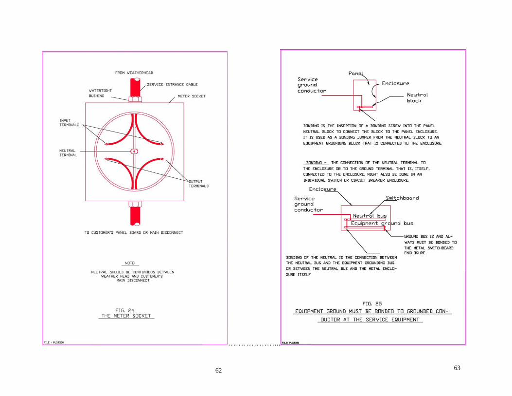
5.1 METER SOCKETS All self-contained meter socket bases are to be supplied and installed by the customer. Self contained type meters may be used for loads up to but not exceeding 200 amps. For services in excess of 200 amps the Company will provide a meter socket base and the required metering current transformers (CTs). Typical Installation of a meter socket is shown in Figure 24. Grounding and bonding is shown in Figures 25 and 26. Location of socket base on the building The meter should be placed in a location that will be accessible at all times to BEL meter readers. In cases where it can be determined that the customer plans to fence the property, the customer may prefer to have an underground supply and place the meter on a column at the boundary of the property. In this case the meter should face outwards towards the roadway. This type of installation is recommended for underground residential distribution. See Figure 16.
5.2 SINGLE METER
INSTALLATIONS a) Type of Socket Base— A 5 jaw socket is required for all 3
wire services with the 5th jaw connected to the neutral conductor. Note that neutral should be continuous through meter socket.
b) Height of Socket— The meter socket should be at a height
of about 1.7m or 5.6ft. above finished grade. Figures 10–15 show typical meter installation for overhead service. Figure 16 shows a typical metering installation for an underground service.
c) Wiring of Socket Base— The wiring in the socket base
should be neat, not bulky, as shown in Figure 24. Any excess wire in the socket base may prevent the meter from being properly inserted into the socket.
d) Security of Socket Base— The meter socket base should
be properly secured to the building or service pedestal. e) Waterproof— The point at which the conduit enters the
meter socket base should be properly sealed to prevent the ingress of water into the socket. All equipment installed outdoors should be designed and rated for outdoor use, as it will be exposed to changes in weather.
32 33

The various meters used by BEL are as follows:
Meter
Use
3-wire Form 2S, CL 100 or
200
Residential, single phase 60 to 200 Amp installation
Form 6S, CL 10
4 wire, wye connected transformers requiring CTs. This meter uses two of the voltage leads and is okay for three
phase metering because of the 2 ½ stator but is not recommended where the phase
to ground voltage are unbalanced. Form 8S Generally used for open delta CT
connected, three phase customers. Form 9S Used for 4 wire, wye connected
transformers requiring CTs. Meter has 3 stators and provides accurate readings for balanced and unbalanced voltages. This meter is recommended instead of
Form 6S. Form 12S Generally used for single phase, 5
terminal installations. However, the meter is best used for 3 wire delta
installations that require self-contained three phase metering.
Form 14S Used for 120/208 V-Wye, 277/480 V-Wye, three phase self-contained
installations that does not require CTs or PTs.
Form 15S Used for 240 V, delta, three phase self-contained installations that do not
require CTs
5.3 METERING CURRENT
TRANSFORMERS (CTS) For services in excess of 200 amps the Company will provide metering current transformers (CTs) for metering. For pad mount transformers, Window Type CTs can be installed by BEL on the secondary bushings of the transformer and the meter located on the side of the padmount transformer Low Voltage compartment. This will only be possible where the transformer provides supply to a single customer. The secondary metering conductors running between the meter and the CTs must be 8 meters (25 feet) or less. Note: In some cases it may be desirable for the Company’s metering CTs to be installed in the customer owned service equipment. Arrangements must be made by the customer with BEL to cover each specific case. In any event the CTs shall be placed in a lockable and sealable enclosure, which is inaccessible from any other portion of the customer’s service equipment.
34 35

5.4 METERING HIGH TENSION
SERVICES In the case of customers who own their transformers and are on the industrial tariff, the Company will normally install High Voltage (HV) Metering facilities. Customers must also note that in the case of customer owned transformers, the service point is located at the disconnect that links the customers installation to B.E.L.’s lines, whether overhead or underground. B.E.L.’s responsibility in such cases end at this service point and the customer is held responsible for the maintenance and upkeep of his installation up to the service point. In all cases the HV Metering Unit will be provided and installed by the Company in a location to be determined by the Company. This may be either a pole mounted unit or a padmount unit. In cases where a padmount HV Metering Unit is required, the customer will be required to provide adequate space and a concrete pad in a suitable location for this to be installed. Provision will need to be made for the meter to be installed in accordance with the other requirements of this booklet so that the meter reader has ready access to read and reset the meter.
6.0 BEL INSPECTIONS
After an application has been received for either a new service or for an existing service for which the wiring has been modified, an inspection is carried out by BEL before the electricity is connected. Note: The Company does not check the customer’s internal wiring. The PUC requires a completed Electrical Installation Form signed by Licensed Wireman before service is connected to BEL lines. Only the original PUC Forms will be accepted by BEL inspectors. BEL Inspectors will ensure the following:
• Service installation meets the required Company standards.
• The necessary infrastructure required to provide the electricity supply are in place and are adequate.
• The Company’s equipment and lines that will service the new Customer are in satisfactory condition.
Once the installation meets the required standards, a meter socket blank is placed over the meter socket and sealed with a Company seal. The service application is then passed for the installation to be carried out. Should the Inspector find anything that does not meet the Company’s standards, the service connection may be delayed until the problem is rectified. For multi-metering installations, the busbar section (splitter box), main breaker panel and line end trunking are also sealed at this time. Current Transformer enclosures are also sealed at this time. Provision needs to be made for fitting the seals. Note: BEL requires the use of standard equipment that is designed and manufactured with provisions for sealing.
3736

6.1 BEL INSPECTION DETAILS The following areas are inspected by the Company’s Inspectors to ensure compliance with the requirements as set out in this booklet.
• Suitability of meter location
• Correct height of socket base
• Correct wiring of socket base
• Suitable material for standard service installation size
• Socket base securely attached to building
• Correct type of socket base
• Correct height and position of weatherhead to meet the all specified clearance requirements.
• Attachment of service drop
• Additional checks on multi-metering installations
• Condition of Existing Distribution System
The Company’s Inspectors are also required to carry out checks to ensure that the service can be fed from the existing Low Voltage (LV) distribution system. • Type of LV distribution. (120/240 Volt or 120/208 Volt
network) • Condition of pole • Height of service drop – greater than 5 meters (16.5 feet) • Distance of service drop – less than 30 meters (98 feet) Delays can be avoided if the electrician or electrical contractor can identify any of the above situations, which do not meet the requirements and notify the Company of these at an early stage. Once an installation has met the Company’s requirements, the Inspectors will blank off the socket base(s) and seal them. Electricians or electrical contractors should never break the Company’s seals on socket bases or unmetered sections. If the seals are found to be broken by our installation crews on arrival, the service will not be installed.
38 39

7.0 PROTECTION OF CUSTOMER
EQUIPMENT While the Company strives to furnish reliable and dependable service, the electricity supply that is available to the Customer through a standard commercial or residential outlet is subject to transient disturbances, dips and surges. There is very little that can be done in the design of an electric utility system about these problems. Contractors should therefore advise their clients of the need to install suitable devices to protect their equipment from possible damage. The type of device selected will depend on the equipment that is to be protected. 7.1 PROTECTION FOR
ELECTRONIC EQUIPMENT Three broad types of devices are available for the protection of sensitive electronic equipment such as computers. • Surge Suppressors • Constant Voltage Stabilizers • Uninterruptible Power Supplies Surge suppressors are devices, which eliminate spikes and surges from the supply, which can damage electronic equipment. These are an economical choice for customers wishing to protect their VCRs, televisions, and similar household equipment from damage. Depending on the nature of their business, Commercial and Industrial Customers are also advised to install surge suppression protection equipment on their electrical installations. Suppressors should be VL1449 rated in accordance with ANSI/IEEE Standard C.62-11.
Constant Voltage Stabilizers provide close voltage regulation and in addition they provide inherent current limiting, thus protecting the electronic system from overloads and short circuits. Uninterruptible Power Supplies will maintain supply to load under power outage conditions. This may be the most appropriate choice for some customers, such as businesses, where the interruption of supply can result in equipment downtime or loss of data on computer systems.
7.2 PROTECTION OF MOTORIZED
EQUIPMENT Motorized installations for refrigeration, air conditioning and other power equipment should be equipped with suitable under-voltage devices to protect against sustained under-voltage or service interruption. Adequate protection should also be provided for over current. Three phase motors should be equipped with suitable protection devices to prevent single-phase operation, improper direction of phase rotation and excessive heating due to over current. The Company will not be responsible in any way for damage to the customer’s equipment due to failure of the customer to provide adequate protection.
41 40

……………...
42 43

……………….
45 44

…………………
46 47

………………..
49 48

………………..
51 50

………………..

………………..
55

……………….
57

……………….
58

………………..
61 60
………………...
63 62

64