belmont station development application - citizen space · belmont station development application...
TRANSCRIPT
Belmont Station Development Application Prepared by: Public Transport Authority Western Australia
FAL-PTAWA-PN-RPT-00002
Belmont Station Development Application Report 2
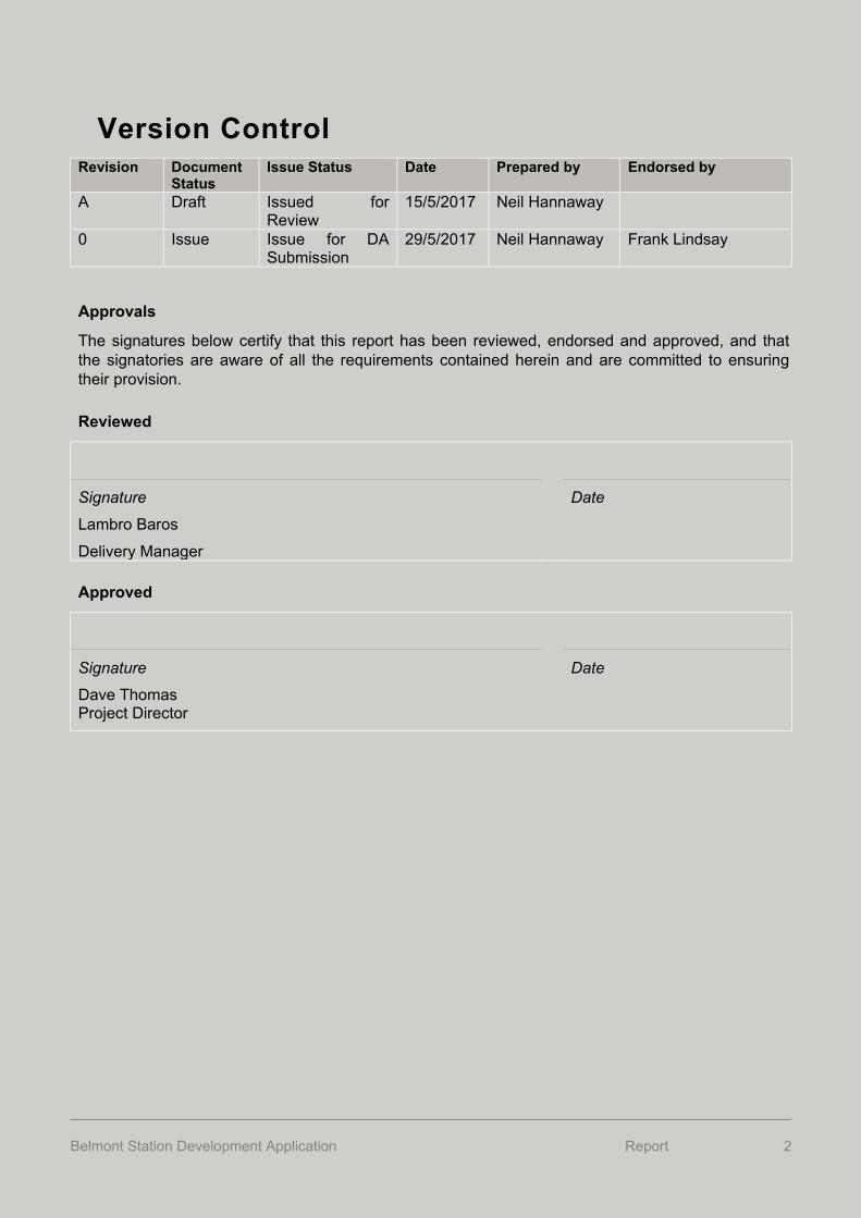
Version Control Revision Document
Status Issue Status Date Prepared by Endorsed by
A Draft Issued for Review
15/5/2017 Neil Hannaway
0 Issue Issue for DA Submission
29/5/2017 Neil Hannaway Frank Lindsay
Approvals
The signatures below certify that this report has been reviewed, endorsed and approved, and that the signatories are aware of all the requirements contained herein and are committed to ensuring their provision.
Reviewed
Signature
Lambro Baros
Delivery Manager
Date
Approved
Signature
Dave Thomas Project Director
Date
Belmont Station Development Application Report 3
Table of Contents 1. Introduction .................................................................................. 5
2. Background .................................................................................. 62.1. Forrestfield-Airport Link Project ............................................ 62.2. Project History ...................................................................... 7
2.3. Delivery Timeframes and Methodology ................................ 8
2.4. Stakeholder Engagement ..................................................... 8
3. Subject Land and Context ........................................................ 103.1. Land Description ................................................................. 11
4. Planning Framework ................................................................. 124.1. State and Metropolitan Strategies ...................................... 124.2. Metropolitan Region Scheme ............................................. 12
4.3. City of Belmont Local Planning Scheme No. 15 ................. 13
4.4. Planning Control Area ........................................................ 15
5. Other Approvals ........................................................................ 175.1. Perth Airport Master Plan ................................................... 17
5.2. Environmental ..................................................................... 17
6. Proposal ..................................................................................... 186.1. Bus Interchange ................................................................. 22
6.2. Kiss and Ride ..................................................................... 236.3. Development and distribution of generated traffic .............. 24
6.4. Signage .............................................................................. 27
6.5. Air Conditioning and Ventilation ......................................... 27
6.6. Interface .............................................................................. 27
7. Description of Construction Works ......................................... 297.1. Major Civil Engineering Works............................................ 29
7.2. Major Structural Engineering Works ................................... 29
8. Stormwater Management .......................................................... 308.1. Existing Infrastructure ......................................................... 30
8.2. Station Drainage ................................................................. 31
9. Access and Mobility .................................................................. 33
Belmont Station Development Application Report 4
9.1. Universal Access ................................................................ 33
9.2. Pedestrian network ............................................................. 33
9.3. Cycling Network .................................................................. 34
9.4. Cycling Facilities ................................................................. 34
9.5. Road Network ..................................................................... 35
9.6. Signage .............................................................................. 35
9.7. Lighting ............................................................................... 36
10. Public Artwork ........................................................................... 37
11. Landscaping and Urban Design ............................................... 38
12. Train Operations ........................................................................ 39
13. Bus Operations .......................................................................... 40
14. Community Engagement .......................................................... 42
14.1. Stakeholder engagement ................................................... 42
14.2. Community engagement .................................................... 43
14.3. Stakeholder and Community Engagement Action Plan ...... 43
14.4. Enquiries, Complaints and Commendations....................... 44
15. Planning Justification ............................................................... 45
15.1. Land Use and Development ............................................... 45
15.2. Environmental Management ............................................... 51
16. Conclusion ................................................................................. 55
Appendix 1: Belmont Station Drawings .......................................... 56
Appendix 2: Transport Assessment ............................................... 57
Appendix 3: Public Transport Authority Accessibility Policy ...... 58
Belmont Station Development Application Report 5
1. Introduction The Public Transport Authority (PTA) has prepared this planning report to support a request to the Western Australian Planning Commission (WAPC) for approval of the new Belmont station, which is part of the Forrestfield-Airport Link Project (the Project).
The concept design for the Project has been prepared by Salini Impreglio NRW JV (SINRW) on and will progress the designs for the Project into the final stages for construction purposes. In light of this D&C delivery methodology, the PTA understands that the WAPC will as a condition of the development application; require the final design for the station precinct to be submitted by the contractor for review in order to ensure it is consistent with the DA6 vision.
The following provides background to the Project, describes the subject land and its context, explains the proposed development and construction works, and provides justification for the proposal having regard for relevant state and local planning considerations.
Belmont Station Development Application Report 6
2. Background
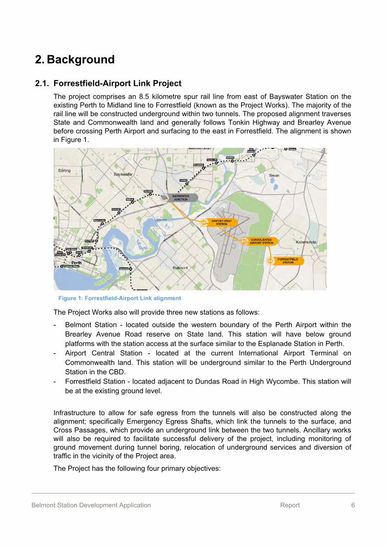
2.1. Forrestfield-Airport Link Project The project comprises an 8.5 kilometre spur rail line from east of Bayswater Station on the existing Perth to Midland line to Forrestfield (known as the Project Works). The majority of the rail line will be constructed underground within two tunnels. The proposed alignment traverses State and Commonwealth land and generally follows Tonkin Highway and Brearley Avenue before crossing Perth Airport and surfacing to the east in Forrestfield. The alignment is shown in Figure 1.
Figure 1: Forrestfield-Airport Link alignment
The Project Works also will provide three new stations as follows:
- Belmont Station - located outside the western boundary of the Perth Airport within the Brearley Avenue Road reserve on State land. This station will have below ground platforms with the station access at the surface similar to the Esplanade Station in Perth.
- Airport Central Station - located at the current International Airport Terminal on Commonwealth land. This station will be underground similar to the Perth Underground Station in the CBD.
- Forrestfield Station - located adjacent to Dundas Road in High Wycombe. This station will be at the existing ground level.
Infrastructure to allow for safe egress from the tunnels will also be constructed along the alignment; specifically Emergency Egress Shafts, which link the tunnels to the surface, and Cross Passages, which provide an underground link between the two tunnels. Ancillary works will also be required to facilitate successful delivery of the project, including monitoring of ground movement during tunnel boring, relocation of underground services and diversion of traffic in the vicinity of the Project area.
The Project has the following four primary objectives:
Belmont Station Development Application Report 7
- provide a quick and efficient connection between the CBD and Perth Airport and promote connections to strategic centres and the general transport network;
- reduce car dependency and improve the public transport network, relieving traffic congestion, therefore improving productivity and available capacity of the road network;
- promote new centres at Belmont and Forrestfield that result in employment, residential and economic growth;
- minimise the impact of the airport as a physical divide, and improve social equity and quality of life for Perth’s community.
The Belmont and Forrestfield stations, Bayswater Junction and an egress shaft, at Abernethy Rd, north of the Forrestfield station, require formal planning approval as described in section 4 of this report. Other works associated with the Project are exempt from planning approval. Land affected by the Belmont and Forrestfield stations and Bayswater Junction are intended to be rezoned under the Metropolitan Region Scheme to reflect the ultimate use and development.
2.2. Project History In 2008-09, the PTA and the Department of Planning (DoP) commissioned a number of studies to assess the feasibility, scope and economic value of rail access to Perth Airport and beyond.
In June 2009, the WAPC released Directions 2031: Draft Spatial Framework for Perth and Peel (Directions 2031), which identified a connection of public transport to the airport as a key element of managing the growth of the metropolitan region.
In July 2010, the PTA’s Annual Report indicated that the investigation into the feasibility of developing a Perth Airport (and surrounds) rail link was nearing completion and preparation of the project master plan would commence in late 2010.
In July 2011, the government released the draft Public Transport for Perth in 2031 for public consultation. The plan included a long term vision for a public transport network to support a population of 3.5 million, including the proposed airport rail link.
In April 2012, Cabinet gave approval for the PTA to develop a Project Definition Plan (PDP) to define the Project’s full scope and cost. The Cabinet approval charged the PTA with ‘developing a final Airport Railway Master Plan by June 2013, which includes options to extend the railway beyond Perth Airport to High Wycombe’. This led to establishment of a specialised project team to deliver the PDP.
In September 2012, the Minister for Transport announced an initial preferred route for the Project which included:
- utilising the Tonkin Highway median; and - boring under the main runways in the Airport to connect to the International Terminal area.
A number of key State Government announcements with respect to the Project have been made:
- March 2013 – during the State Election campaign the State Government announced its intention of bringing the Project forward;
Belmont Station Development Application Report 8
- August 2013 – WA State Budget 2013-14 confirmed investment in the Project with the Treasurer advising ‘Construction will start in 2016 with a scheduled finish in 2019’;
- December 2013 – WA Mid-Year Budget Review confirmed further commitment to the Project with a completion date in 2020 to reflect the time necessary to develop and deliver the project; and
- May 2014 – WA State Budget 2014-15 confirmed the Project was a key project in the Asset Investment Program with an allocation of $683 million over the next four years.
- March 2015 – Five Expressions of Interest were received for the $2 billion project. - April 2015 – Three consortia were short-listed to design and construct the project. - April 2016 contract awarded to Salini Impreglio-NRW Joint Venture (SINRW-JV).
2.3. Delivery Timeframes and Methodology Concept designs have been prepared by Aurecon HASSELL on behalf of the PTA to inform the brief for the design and construct contract for the Project. SINRW_JV have completed updated concept designs for Belmont Station and Forrestfield Station. This planning report is based on the concept designs for Belmont Station.
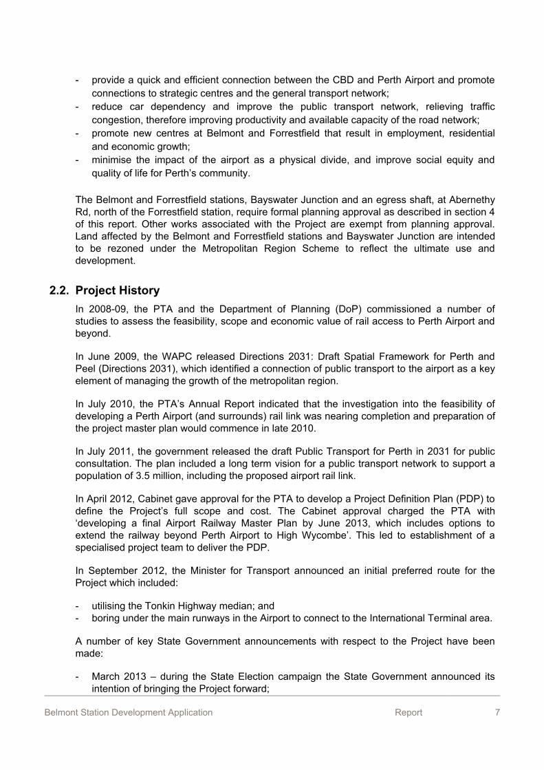
The PTA has identified the following timeframes for the works requiring planning approval:
Table 1: Proposed project timeframes
Belmont Station Forrestfield Station Abernethy Road Egress Shaft
Land ownership by PTA Dec 2016 Nov 2015 Feb 2016
Design and Construct Contract Awarded
Apr 2016
Design and Approvals Jun 2016 – Jun 2018 May 2016 – Dec
2019 Aug 2016 – Mar 2017
Construction/ Fitout Jul 2017 – Feb 2020 Nov 2016 – Jul
2019 Mar 2017 – Feb 2018
Rail/Tunnel Commissioning and Handover
Feb – Oct 2020
First Train Operating Late 2020
2.4. Stakeholder Engagement The PTA has undertaken consultation with the following stakeholders during the planning phase of the Project:
- Perth Airport Pty Ltd;
Belmont Station Development Application Report 9
- Department of Infrastructure and Regional Development (federal); - Department of the Environment (federal); - Environmental Protection Authority; - Office of the Environmental Protection Authority; - Department of Environment Regulation; - Department of Health; - Department of Water; - Department of Aboriginal Affairs; - Department of Premier and Cabinet; - South West Aboriginal Land and Sea Council; - Whadjuk Working Group; - Department of Parks and Wildlife; - Swan River Trust; - Department of Planning; - Western Australian Planning Commission; - Water Corporation; - City of Bayswater; - City of Belmont; - Shire of Kalamunda; - Main Roads WA.
The concept designs for the stations have been informed by stakeholder meetings attended by representatives of the PTA, DoP, PAPL and the City of Belmont.
The PTA has also liaised closely with Main Roads WA in respect to Brearley Avenue for the Belmont Station.
The PTA has also undertaken preliminary consultation with all Service Authorities, including Western Power and Water Corporation to establish the extent of existing services in the vicinity of the station.
Belmont Station Development Application Report 10
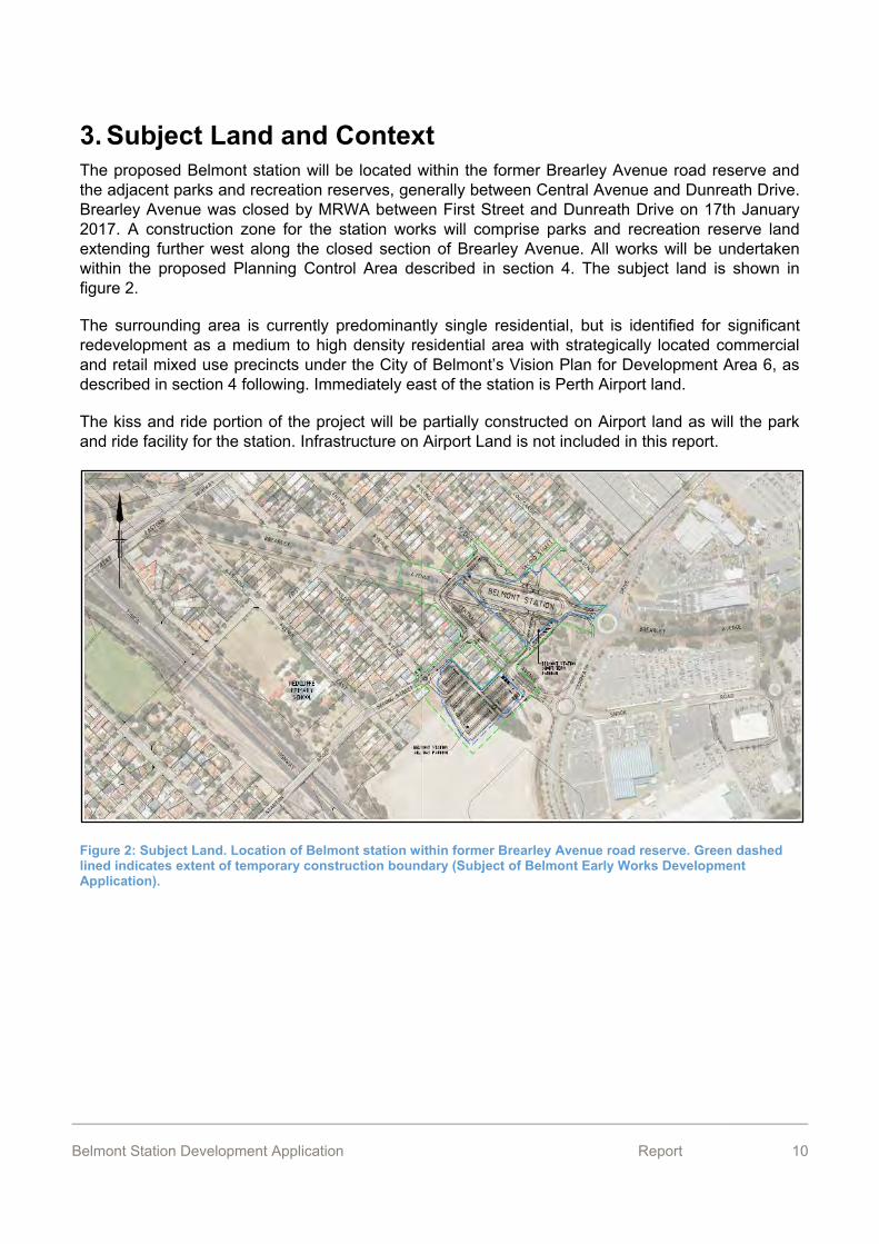
3. Subject Land and Context The proposed Belmont station will be located within the former Brearley Avenue road reserve and the adjacent parks and recreation reserves, generally between Central Avenue and Dunreath Drive. Brearley Avenue was closed by MRWA between First Street and Dunreath Drive on 17th January 2017. A construction zone for the station works will comprise parks and recreation reserve land extending further west along the closed section of Brearley Avenue. All works will be undertaken within the proposed Planning Control Area described in section 4. The subject land is shown in figure 2.
The surrounding area is currently predominantly single residential, but is identified for significant redevelopment as a medium to high density residential area with strategically located commercial and retail mixed use precincts under the City of Belmont’s Vision Plan for Development Area 6, as described in section 4 following. Immediately east of the station is Perth Airport land.
The kiss and ride portion of the project will be partially constructed on Airport land as will the park and ride facility for the station. Infrastructure on Airport Land is not included in this report.
Figure 2: Subject Land. Location of Belmont station within former Brearley Avenue road reserve. Green dashed lined indicates extent of temporary construction boundary (Subject of Belmont Early Works Development Application).
Belmont Station Development Application Report 11
3.1. Land Description The station is located predominantly on Brearley Ave, though a number of adjoining properties are also impacted. All properties are within government ownership and are listed in the following table:
Table 2: Land Description
Street Name Description Title Plan and Lot Owner
Brearley Ave,
Redcliffe Road N/A PIN11802563 State of WA/MRWA
Brearley Ave,
Redcliffe Crown
Reserve LR3026/114 600P406484 State of WA. Management Order
to PTAWA
149 Bulong Ave,
Redcliffe Reserve LR3155/693 9562P182307 State of WA. Management Order
with PTAWA
Second St,
Redcliffe Reserve LR3154/490 4875P188867 State of WA. Management Order
to City of Belmont
Brearley Ave,
Redcliffe Reserve R27446 SwanLoc7804 State of WA. Management Order
to City Of Belmont
Brearley Ave,
Redcliffe Drainage LR3142/667 8540P9144 State of WA Management Order
to Water Corporation. Licenced
to PTA
Brearley Ave,
Redcliffe Drainage 1320/105 102P9144 Water Corporation. Licenced to
PTA
Brearley Ave,
Redcliffe Drainage 1320/103 101P9144 Water Corporation. Licenced to
PTA
Brearley Ave,
Redcliffe Drainage 366/103 100P9144 Water Corporation. Licenced to
PTA
Belmont Station Development Application Report 12
4. Planning Framework
4.1. State and Metropolitan Strategies The following State and metropolitan planning strategies and policies are relevant to the proposal:
- State Planning Strategy 2050; - Statement of Planning Policy No. 3: Urban Growth and Settlement; - Directions 2031 and Beyond; - Draft Perth and Peel @3.5million and Central Sub-Regional Planning Framework; - State Planning Policy 5.1: Land Use Planning In The Vicinity Of Perth Airport; - State Planning Policy 5.4: Road and Rail Transport Noise and Freight
Considerations in Land Use Planning; - Draft State Planning Policy 7: Design of the Built Environment - Development Control Policy 1.6: Planning to Support Transit Use and Transit
Oriented Development;
Compliance with the above is discussed in section 15.
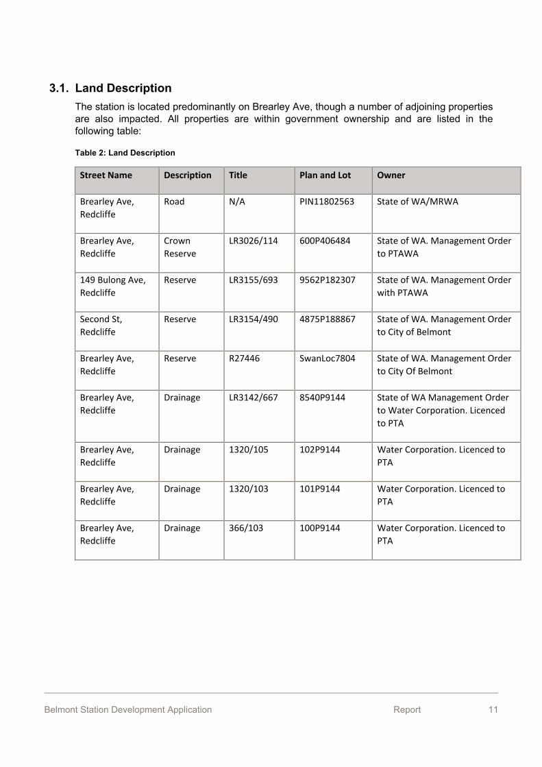
4.2. Metropolitan Region Scheme
Figure 3: Metropolitan Region Scheme
The subject land is currently zoned ‘Urban’ under the Metropolitan Region Scheme (refer to Figure 3).
Land affected by the rail station, bus interchange and kiss and ride facilities will be reserved under the Metropolitan Region Scheme as railways via a separate application.
While section 6 of the Planning and Development Act 2005 makes exemptions for the need to obtain development approval for public works under a local planning scheme, Section 5(2) states that a region planning scheme binds the Crown, meaning approval for the proposed public works is required under the Metropolitan Region Scheme.
Belmont Station Development Application Report 13
4.3. City of Belmont Local Planning Scheme No. 15 4.3.1 Zoning
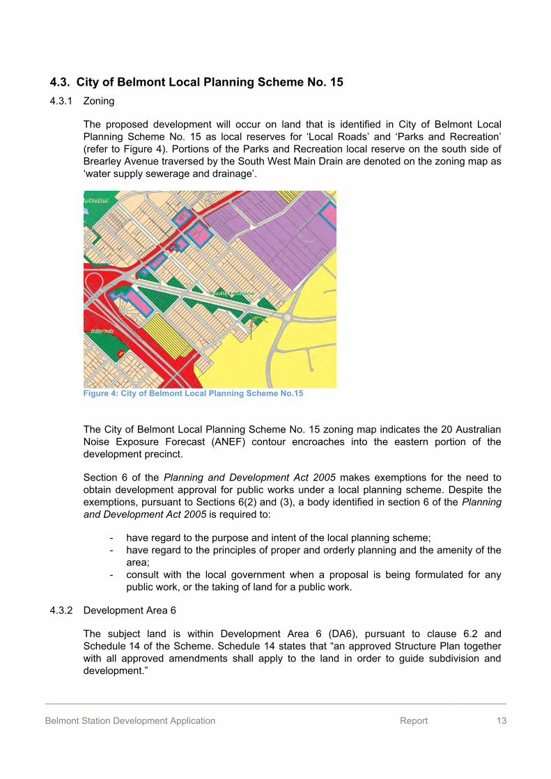
The proposed development will occur on land that is identified in City of Belmont Local Planning Scheme No. 15 as local reserves for ‘Local Roads’ and ‘Parks and Recreation’ (refer to Figure 4). Portions of the Parks and Recreation local reserve on the south side of Brearley Avenue traversed by the South West Main Drain are denoted on the zoning map as ‘water supply sewerage and drainage’.
The City of Belmont Local Planning Scheme No. 15 zoning map indicates the 20 Australian Noise Exposure Forecast (ANEF) contour encroaches into the eastern portion of the development precinct.
Section 6 of the Planning and Development Act 2005 makes exemptions for the need to obtain development approval for public works under a local planning scheme. Despite the exemptions, pursuant to Sections 6(2) and (3), a body identified in section 6 of the Planning and Development Act 2005 is required to:
- have regard to the purpose and intent of the local planning scheme; - have regard to the principles of proper and orderly planning and the amenity of the
area; - consult with the local government when a proposal is being formulated for any
public work, or the taking of land for a public work.
4.3.2 Development Area 6
The subject land is within Development Area 6 (DA6), pursuant to clause 6.2 and Schedule 14 of the Scheme. Schedule 14 states that “an approved Structure Plan together with all approved amendments shall apply to the land in order to guide subdivision and development.”
Figure 4: City of Belmont Local Planning Scheme No.15
Belmont Station Development Application Report 14
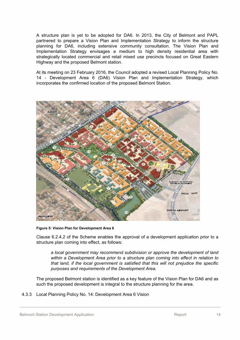
A structure plan is yet to be adopted for DA6. In 2013, the City of Belmont and PAPL partnered to prepare a Vision Plan and Implementation Strategy to inform the structure planning for DA6, including extensive community consultation. The Vision Plan and Implementation Strategy envisages a medium to high density residential area with strategically located commercial and retail mixed use precincts focused on Great Eastern Highway and the proposed Belmont station.
At its meeting on 23 February 2016, the Council adopted a revised Local Planning Policy No. 14 - Development Area 6 (DA6) Vision Plan and Implementation Strategy, which incorporates the confirmed location of the proposed Belmont Station.
Figure 5: Vision Plan for Development Area 6
Clause 6.2.4.2 of the Scheme enables the approval of a development application prior to a structure plan coming into effect, as follows:
a local government may recommend subdivision or approve the development of land within a Development Area prior to a structure plan coming into effect in relation to that land, if the local government is satisfied that this will not prejudice the specific purposes and requirements of the Development Area.
The proposed Belmont station is identified as a key feature of the Vision Plan for DA6 and as such the proposed development is integral to the structure planning for the area.
4.3.3 Local Planning Policy No. 14: Development Area 6 Vision

Belmont Station Development Application Report 15
Pursuant to clause 2.4 of the Scheme, the City of Belmont has prepared Local Planning Policy No. 14 for the following purpose:
to articulate the City of Belmont and Perth Airport Pty Ltd’s vision for Development Area 6. The Policy will assist in providing direction for the future planning and progression of detailed structure planning for the precinct.
Clause 4.4 of the policy makes provision for approval of the development application for the Belmont station prior to the approval of a structure plan, as follows:
a decision-maker may approve the development and/or a change in land use within Development Area 6 prior to a structure plan coming into effect where the City of Belmont is satisfied that the proposal is clearly consistent with the Vision Plan for Development Area 6 and will not have any prejudicial outcomes for the implementation of the Vision.
As noted above, the proposed Belmont station is identified as a key feature of Vision Plan for DA6 and as such the proposed development is integral to, and will not prejudice the future planning for the area.
4.3.4 Westralia Airports Corporation Structures Height Control Contours Map
Pursuant to clause 5.20 of the local planning scheme, structures must not exceed the heights indicated in the Westralia Airports Corporation (now PAPL) Structures Height Control Contours Map contained in Schedule No. 12 of the scheme. The subject land is located between the 40 and 50 metre contours of this map, and is not within an area where applications for development are required to be referred to the Westralia Airports Corporation for comment. The proposed Belmont station is well within these height limits.
4.4. Planning Control Area The proposed Belmont station and associated works are located within Planning Control Area No. 116, pursuant to Part 7 of the Planning and Development Act 2005.

Belmont Station Development Application Report 16
Figure 6: Planning Control Area
A Planning Control Area (PCA) has been declared at Belmont Station. The PCA specify that the Western Australian Planning Commission (WAPC) is to be the sole determining authority on any development applications within this PCA.
Therefore, a formal development application for works within a PCA is required to be submitted to the local government, which, within 30 days of receiving the application, is to forward the application and its recommendation to the WAPC for determination.

Belmont Station Development Application Report 17
5. Other Approvals
5.1. Perth Airport Master Plan Under the requirements of the Airports Act 1996, at least every five years Perth Airport is required to prepare a master plan that outlines proposed developments for the next 20 years. In January 2015, the Deputy Prime Minister and Minister for Infrastructure and Regional Development approved the Perth Airport Master Plan 2014.
In respect to approval requirements for the Project, the Master Plan notes:
Within the Commonwealth controlled land of Perth Airport, the Forrestfield-Airport Link project will require the relevant approvals, including a Major Development Plan approval under the Airports Act 1996 (Cth) and a Section 18 Approval under the Aboriginal Heritage Act 1972 (WA).
Whilst the proposed station is located outside of Perth Airport land, the PTA park and ride facility of approximately 500 bays that is associated with the station is located south of Central Avenue and east of Second Street, within Perth Airport land. Approval for this facility is will be sought in parallel with this report. Also, the proposed kiss-and-ride is partially located on Airport land and will be subject to the relevant PAPL and Airport Building Controller (ABC) permit and consent process. There is currently a Development Agreement between PTA and PAPL which deals with both access arrangements and proposed developments on Airport land.
5.2. Environmental The Project is subject to various environmental approvals under the following legislation:
- Environmental Protection Act 1986; - Environmental Protection (Noise) Regulations 1997; - Contaminated Sites Act 2003; - Rights in Water and Irrigation Act 1914; - Aboriginal Heritage Act 1972.
The PTA’s proposed environmental management framework for the Project, which addresses the above, is described in section 15.2.

Belmont Station Development Application Report 18
6. Proposal The proposal for the Belmont station is attached as Appendix 1. This design was developed by the D&C contractor and is currently at the concept stage.
The Belmont station will comprise below ground platforms, with the station access at the surface, similar to the Elizabeth Quay Station in Perth.
A PTA station Park and Ride car park of approximately 500 bays is to be located south of Central Avenue and east of Second Street, on Perth Airport land and is therefore subject to separate approval under Commonwealth processes.
The concept design identifies the need for various modifications to the road network immediately surrounding the proposed Belmont station, including:
- partial closure of Brearley Avenue (completed); - closure of Second Street between Central Avenue and Brearley Avenue (completed); - a new busway around the station with provision to accommodate bus stands; - a modified bus connection from the Dunreath Drive/Brearley Avenue roundabout to the
station; - a new road west of the station between Central Avenue and Bulong Avenue with a bus
connection to the station; - a new roundabout at the intersection of Second Street and Boulder Avenue including
tie in with a new road leading from the roundabout to the proposed Park and Ride car park within Perth Airport land; and
- minor modifications along Central Avenue, Second Street, Boulder Avenue and Bulong Avenue to tie in the above works with existing roads and footpaths.
The functional requirements of the station are identified as follows:
Platforms:
- Belmont Station comprises 1 x 150 m long and minimum 11.4 m wide island platform that cater to 6-car sets.
- The platform is located below the entry concourse. The location of the concourse encourages an even distribution of passengers.
- The platform is served by two lifts (with stretcher capacity), two escalators (with allowance for future expansion to four) and a stairways.
- Emergency egress stairs are located at the ends of the platform. - Drivers’ toilet and platform staff booth are also provided.
Belmont Station Development Application Report 19
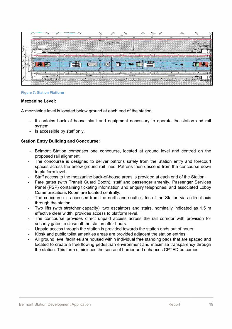
Figure 7: Station Platform
Mezzanine Level:
A mezzanine level is located below ground at each end of the station.
- It contains back of house plant and equipment necessary to operate the station and rail system.
- Is accessible by staff only.
Station Entry Building and Concourse:
- Belmont Station comprises one concourse, located at ground level and centred on the proposed rail alignment.
- The concourse is designed to deliver patrons safely from the Station entry and forecourt spaces across the below ground rail lines. Patrons then descend from the concourse down to platform level.
- Staff access to the mezzanine back-of-house areas is provided at each end of the Station. - Fare gates (with Transit Guard Booth), staff and passenger amenity, Passenger Services
Panel (PSP) containing ticketing information and enquiry telephones, and associated Lobby Communications Room are located centrally.
- The concourse is accessed from the north and south sides of the Station via a direct axis through the station.
- Two lifts (with stretcher capacity), two escalators and stairs, nominally indicated as 1.5 m effective clear width, provides access to platform level.
- The concourse provides direct unpaid access across the rail corridor with provision for security gates to close off the station after hours.
- Unpaid access through the station is provided towards the station ends out of hours. - Kiosk and public toilet amenities areas are provided adjacent the station entries. - All ground level facilities are housed within individual free standing pads that are spaced and
located to create a free flowing pedestrian environment and maximise transparency through the station. This form diminishes the sense of barrier and enhances CPTED outcomes.
Belmont Station Development Application Report 20
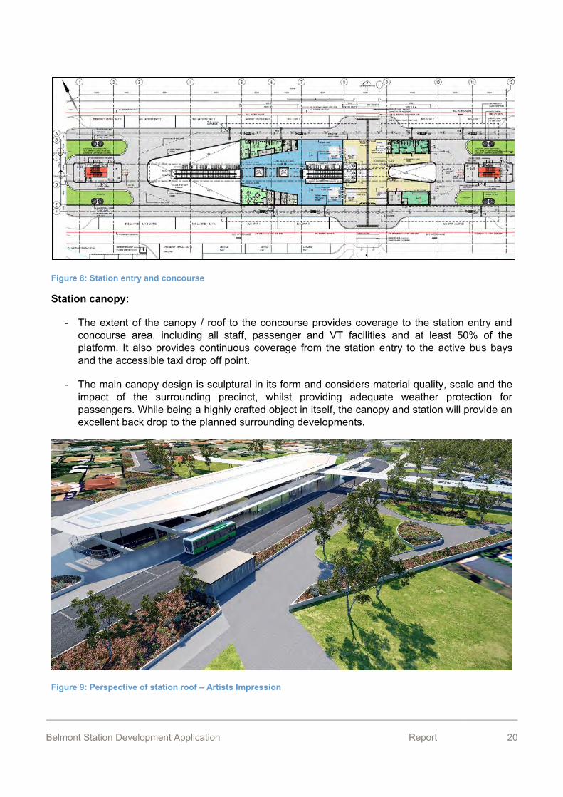
Figure 8: Station entry and concourse
Station canopy:
- The extent of the canopy / roof to the concourse provides coverage to the station entry and concourse area, including all staff, passenger and VT facilities and at least 50% of the platform. It also provides continuous coverage from the station entry to the active bus bays and the accessible taxi drop off point.
- The main canopy design is sculptural in its form and considers material quality, scale and the impact of the surrounding precinct, whilst providing adequate weather protection for passengers. While being a highly crafted object in itself, the canopy and station will provide an excellent back drop to the planned surrounding developments.
Figure 9: Perspective of station roof – Artists Impression
Belmont Station Development Application Report 21
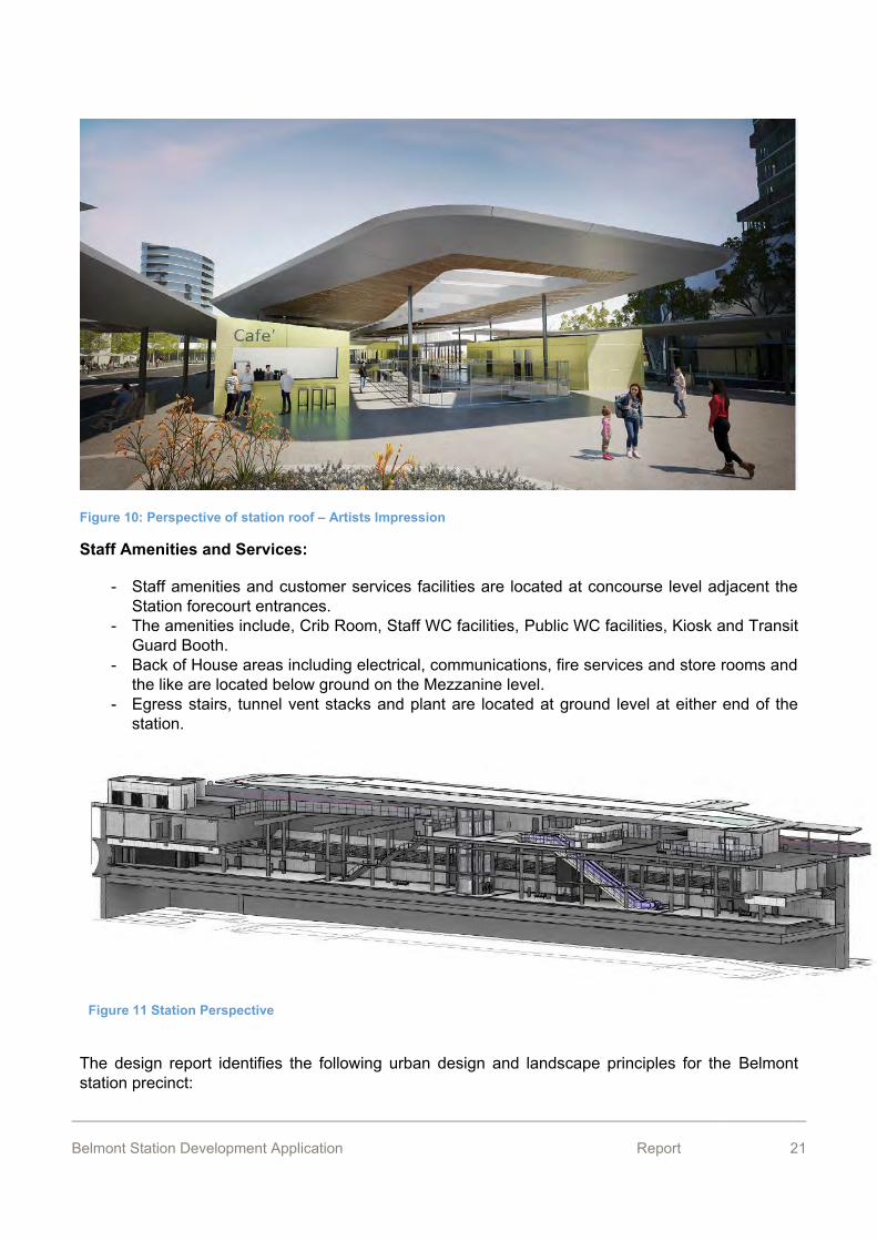
Figure 10: Perspective of station roof – Artists Impression
Staff Amenities and Services:
- Staff amenities and customer services facilities are located at concourse level adjacent the Station forecourt entrances.
- The amenities include, Crib Room, Staff WC facilities, Public WC facilities, Kiosk and Transit Guard Booth.
- Back of House areas including electrical, communications, fire services and store rooms and the like are located below ground on the Mezzanine level.
- Egress stairs, tunnel vent stacks and plant are located at ground level at either end of the station.
The design report identifies the following urban design and landscape principles for the Belmont station precinct:
Figure 11 Station Perspective
Belmont Station Development Application Report 22
- Response to the removal Brearley Avenue and creation of lineal open space network. - Integration of the lineal open space with the station forecourt as a major pedestrian and
cycle connection. - Opportunities for improved open space amenity to support higher density residential
development including a new play space associated with the station forecourt. - Clearly defined pedestrian priority crossings over the bus loop. - Incorporation of landscape treatments at the east and west end of the station to improve the
shelter and amenity of the station, screen plant rooms and reduce expanses of concrete. - Direct, legible and safe pedestrian connections through the station car park and to the
station. - Allowance for future development sites to minimise redundant public realm and civil works. - Maximise the retention of existing mature trees from Brearley Avenue.
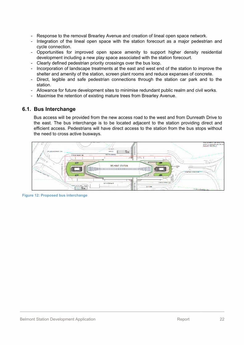
6.1. Bus Interchange Bus access will be provided from the new access road to the west and from Dunreath Drive to the east. The bus interchange is to be located adjacent to the station providing direct and efficient access. Pedestrians will have direct access to the station from the bus stops without the need to cross active busways.
Figure 12: Proposed bus interchange
Belmont Station Development Application Report 23
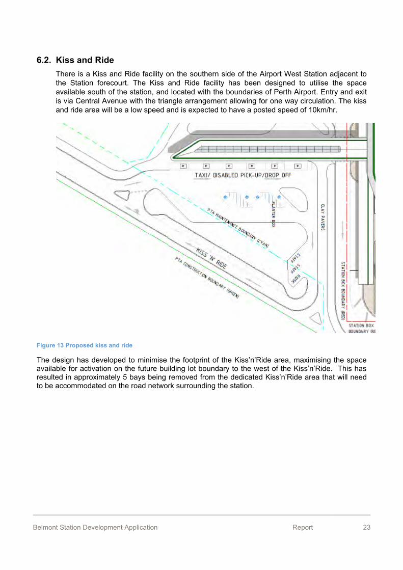
6.2. Kiss and Ride There is a Kiss and Ride facility on the southern side of the Airport West Station adjacent to the Station forecourt. The Kiss and Ride facility has been designed to utilise the space available south of the station, and located with the boundaries of Perth Airport. Entry and exit is via Central Avenue with the triangle arrangement allowing for one way circulation. The kiss and ride area will be a low speed and is expected to have a posted speed of 10km/hr.
Figure 13 Proposed kiss and ride
The design has developed to minimise the footprint of the Kiss’n’Ride area, maximising the space available for activation on the future building lot boundary to the west of the Kiss’n’Ride. This has resulted in approximately 5 bays being removed from the dedicated Kiss’n’Ride area that will need to be accommodated on the road network surrounding the station.
Belmont Station Development Application Report 24
6.3. Development and distribution of generated traffic 6.3.1 Trip generation
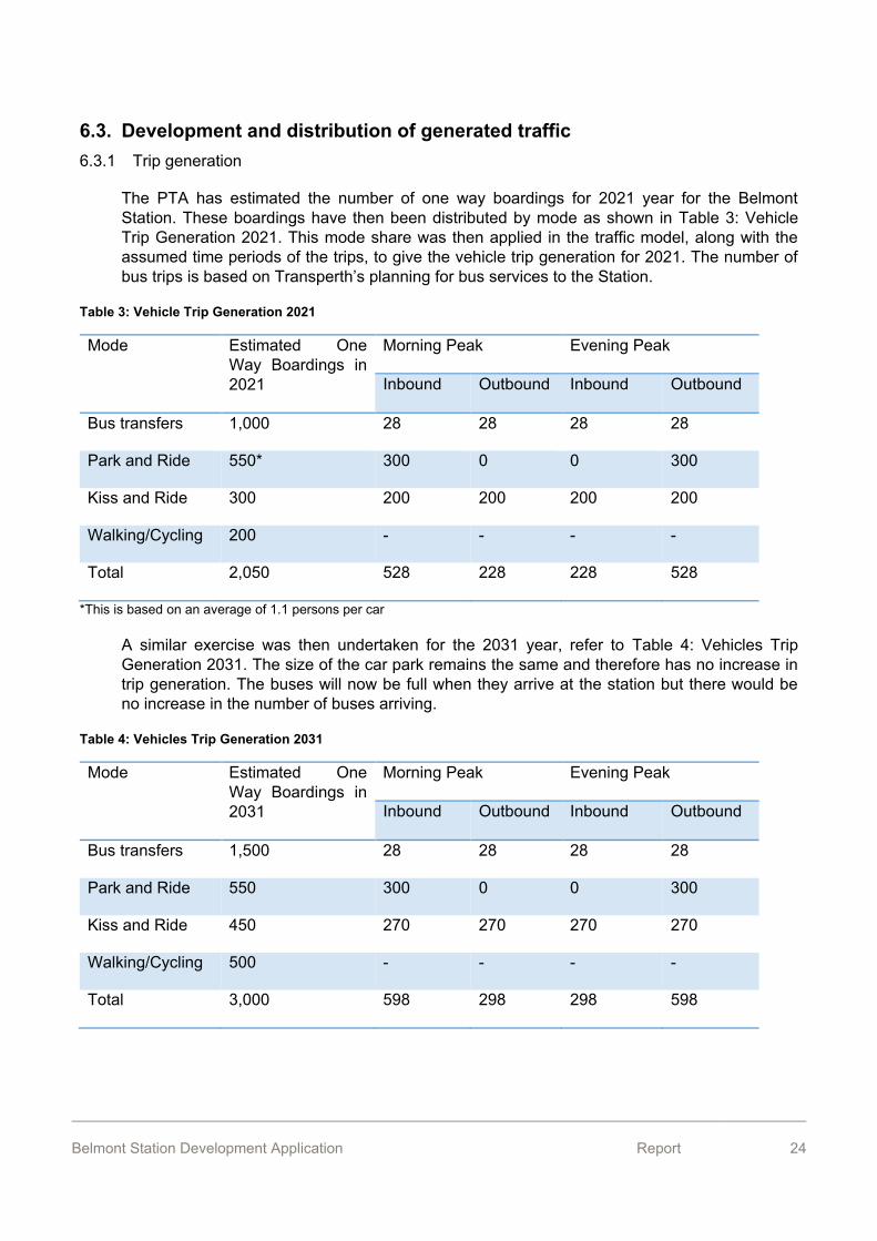
The PTA has estimated the number of one way boardings for 2021 year for the Belmont Station. These boardings have then been distributed by mode as shown in Table 3: Vehicle Trip Generation 2021. This mode share was then applied in the traffic model, along with the assumed time periods of the trips, to give the vehicle trip generation for 2021. The number of bus trips is based on Transperth’s planning for bus services to the Station.
Table 3: Vehicle Trip Generation 2021
Mode Estimated One Way Boardings in 2021
Morning Peak Evening Peak
Inbound Outbound Inbound Outbound
Bus transfers 1,000 28 28 28 28
Park and Ride 550* 300 0 0 300
Kiss and Ride 300 200 200 200 200
Walking/Cycling 200 - - - -
Total 2,050 528 228 228 528
*This is based on an average of 1.1 persons per car
A similar exercise was then undertaken for the 2031 year, refer to Table 4: Vehicles Trip Generation 2031. The size of the car park remains the same and therefore has no increase in trip generation. The buses will now be full when they arrive at the station but there would be no increase in the number of buses arriving.
Table 4: Vehicles Trip Generation 2031
Mode Estimated One Way Boardings in 2031
Morning Peak Evening Peak
Inbound Outbound Inbound Outbound
Bus transfers 1,500 28 28 28 28
Park and Ride 550 300 0 0 300
Kiss and Ride 450 270 270 270 270
Walking/Cycling 500 - - - -
Total 3,000 598 298 298 598

Belmont Station Development Application Report 25
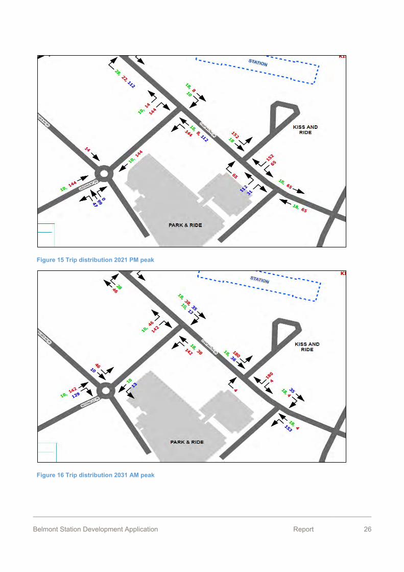
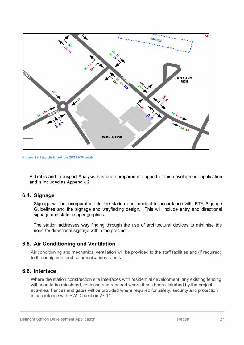
6.3.2 Trip distribution
An Aimsun hybrid model, containing both a microscopic and mesoscopic model area, has been built for FAL. A hybrid model was chosen as it allows for individual vehicles, including buses and heavy vehicles, to be modelled in the detailed micro-simulation cordon environment around Belmont Station, Consolidated Station and Forrestfield Station. Outside the micro-simulation cordon environment consists of the broader model network operating as a mesoscopic model with a simplified model engine. The study area is approximately bounded by four key highways: Tonkin, Great Eastern, Great Eastern Highway Bypass and Roe Highway.
The trip distribution from the model was used as the basis for the Belmont Station, as shown in 14 through to Figure 17.
Figure 14 Trip distribution AM 2021 peak
Belmont Station Development Application Report 26
Figure 15 Trip distribution 2021 PM peak
Figure 16 Trip distribution 2031 AM peak
Belmont Station Development Application Report 27
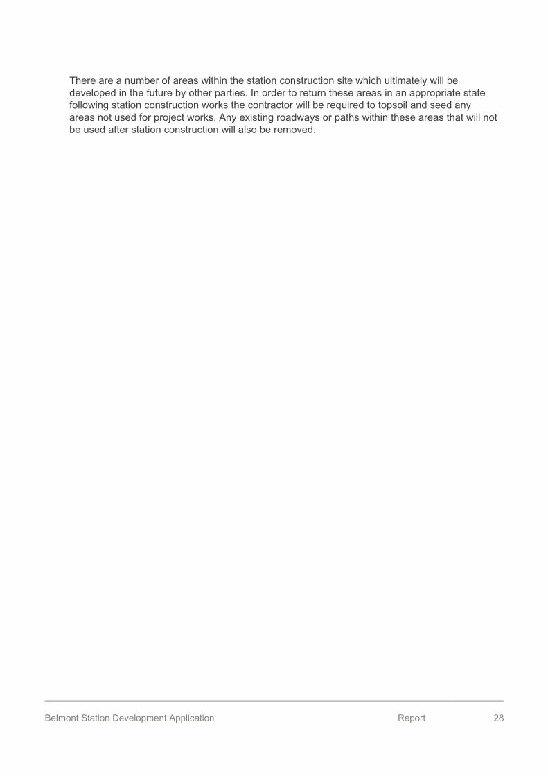
Figure 17 Trip distribution 2031 PM peak
A Traffic and Transport Analysis has been prepared in support of this development application and is included as Appendix 2.
6.4. Signage Signage will be incorporated into the station and precinct in accordance with PTA Signage Guidelines and the signage and wayfinding design. This will include entry and directional signage and station super graphics.
The station addresses way finding through the use of architectural devices to minimise the need for directional signage within the precinct.
6.5. Air Conditioning and Ventilation Air conditioning and mechanical ventilation will be provided to the staff facilities and (if required) to the equipment and communications rooms.
6.6. Interface Where the station construction site interfaces with residential development, any existing fencing will need to be reinstated, replaced and repaired where it has been disturbed by the project activities. Fences and gates will be provided where required for safety, security and protection in accordance with SWTC section 27.11.
Belmont Station Development Application Report 28
There are a number of areas within the station construction site which ultimately will be developed in the future by other parties. In order to return these areas in an appropriate state following station construction works the contractor will be required to topsoil and seed any areas not used for project works. Any existing roadways or paths within these areas that will not be used after station construction will also be removed.
Belmont Station Development Application Report 29
7. Description of Construction Works The Belmont Station is proposed to be a partially underground station with underground works, similar in form to the station constructed at Esplanade on the Mandurah Line in Perth or Subiaco on the Fremantle line. The station box will have an island platform at track level at an approximate depth of 10m with the concourse level with ticketing and station facilities at ground level under a canopy roof structure.
7.1. Major Civil Engineering Works The major civil engineering works relate to and will include the following activities.
- Ventilation of the tunnels once the TBMs have passed for the duration of construction works.
- Station Forecourt – passenger and bus facilities including roadways and shelters. - Car Parks – provision of asphalted car park area for up to 500 vehicles including
necessary drainage, lighting towers and payment infrastructure. - Some minor utilities relocation and cutting and capping to facilitate the station box
construction. - Roadworks – generally around the station including the busway.
In addition to the above but not the subject of this report, the following activities will be undertaken. These activities have been approved under the Belmont Station Early Works Development Application.
- Construction of the station box structure – using diaphragm wall techniques with the panels extending into the Osborne Formation bed rock at approximately 22.5m depth below ground surface level to provide groundwater cut-off.
- Station box excavation – once the diaphragm walls are complete the box will be excavated and the base slab constructed to seal the box for the TBM arrival. The depth of excavation will be approximately 12.8m below ground level.
- Removal of spoil from the Project Works via Dunreath Ave and Tonkin Hwy. - Dewatering – required for the station box excavation with the groundwater to be
infiltrated back into the aquifer locally. Recharge bores are proposed to be located within the Belmont Station site boundaries, to the north and south of the constructed station box.
- Ground improvement – outside the tunnel portal eyes in the station box using jet grouting of deep soil mixing.
7.2. Major Structural Engineering Works The major structural engineering works relate to and will entail the following activities:
- Station Platform – island platform in-between twin rail tracks - Station Structure:
o vertical transportation o concourse level and roof structure; o passenger and ticketing facilities; and o communications antennae
Belmont Station Development Application Report 30
In addition to the above, the following structural works will be completed as part of the station works. The station box construction has been approved under the Belmont Station Early Works Development Application.
- Station Box – diaphragm walls approximately 22.5m in length. - Twin bore tunnels approximately 7m external diameter each.
Further structural and civil engineering works may be required depending on the ultimate construction methodology. The final construction works will be detailed in a Construction Environmental Management Plan. Required materials including any precast units will be transported to the site via Dunreath Ave and not through the local road system. It is acknowledged that the site is within close proximity to residents and various measures will be undertaken as necessary to meet legal noise limits.
8. Stormwater Management The drainage design will be undertaken in accordance with the following standards and guidelines:
- Main Roads WA standard drainage drawings. - Main Roads WA drainage/waterways design guidelines. - Department of Water, Stormwater Management Manual for Western Australia. - Department of Water, Decision process for stormwater management in WA. - Institution of Engineers Australia, Australian Rainfall and Runoff: A Guide to Flood - Estimation, Volumes 1 and 2 (1987). - Austroads Guide to Road Design, Parts 5, 5A and 5B – Drainage. - Water Corporation Standard DS 66
In addition, the Project’s Scope of Work and technical Criteria (SWTC) Clauses 27.9(g)(ii) and (iii) state the following requirements that will be complied with:
- For transverse drainage systems the minimum pipe culvert size must be 450 mm nominal diameter.
- The minimum pipe size must be 300 mm diameter, but can be smaller to match an existing pipe.
- The minimum pipe size for main roads must be 450 mm diameter downstream of a sag inlet located at a low point.
- The maximum length of pipe without an intermediate pit must be 100 m. - Drainage pipes must be RCP (reinforced concrete pipe) to AS/NZS 4058 – Precast concrete
pipes (pressure and non-pressure).
8.1. Existing Infrastructure The Southern Main Drain (SMD), which traverses Perth Airport land has been diverted from its original course to run beneath Central Avenue via twin 1500mm diameter concrete pipes. The diverted drain re-connects with the original drain on Brearley Avenue downstream from the station construction site.
Belmont Station Development Application Report 31
The drain was diverted in order to provide unrestricted access to the construction site. The works were carried out by PTA as part of the Forward Works program for the FAL project.
8.2. Station Drainage The station drainage system must accommodate runoff from all new and affected infrastructure including railways, busways, roads, paths and above-ground station areas, including adjacent verges and earthworks, and all runoff affected by the Project Works.
Drainage and protection works will be designed to:
- Minimise interruption to existing drainage systems or modification of surface-flow patterns;
- Manage all runoff and avoid ponding; - Protect the Project Works from water ingress; - Prevent scour, erosion and sediment transportation; - Ensure employee and public safety; - Avoid adverse impacts on the environment; - Minimise flow across paths and roads from adjacent landscaped areas; - Minimise the need for maintenance such as scour repair and the removal of sediment
deposits; - Allow for the effects of any existing drainage features on or adjacent to the
Construction Site; and - Maintain the existing flow regimes, water balance and stormwater quality of the
Construction Site as much as possible.
The proposed strategy for road (both surrounding the carpark and adjacent the station) drainage involves the use of a piped system. The design utilises a combination of gully pits and side entry pits (SEPs) although gully pits are preferred due to their ability to capture more runoff leading to reduced flood widths and greater pit spacing.
The proposed pit and pipe network is located generally away from the road pavement underneath the verge or through car parking areas, which will result in less disruption to traffic during future maintenance activities. Connection points into the proposed network have been provided to the north and south of the station building for roof runoff. It is currently assumed that the station building runoff will not require compensation prior to discharge into the street drainage system. These proposed connection locations are shown on the concept design drawings and subject to confirmation when detailed design of the roof drainage is undertaken.
The drainage network conveys flows from Busway Access East to Central Avenue with a headwall connection into the open section of the existing SMD below the recently installed pipeline and headwall.
The drainage solution for the short-term car park is under development in consultation with the City of Belmont and PAPL. This will ultimately drain into the pit and pipe network via an overflow pit and low level outlet pipe. It is expected that in major events water may be directed along an overland flow path on the proposed roadway.
Belmont Station Development Application Report 32
The design of the road network and long term car park will consider the need to provide suitable overland flow paths during major storm events such that key infrastructure including the station, existing buildings and future developments are protected whilst providing suitable freeboards. Existing flood modelling will be reviewed during the future design stages to confirm potential risk from local (street drainage) and regional (SMD) flooding and integrated into the design.
Drainage and protection works will be designed to:
- Minimise interruption to existing drainage systems or modification of surface-flow patterns;
- Manage all runoff and avoid ponding; - Protect the Project Works from water ingress; - Prevent scour, erosion and sediment transportation; - Ensure employee and public safety; - Avoid adverse impacts on the environment; - Minimise flow across paths and roads from adjacent landscaped areas; - Minimise the need for maintenance such as scour repair and the removal of sediment
deposits; - Allow for the effects of any existing drainage features on or adjacent to the
Construction Site; and - Maintain the existing flow regimes, water balance and stormwater quality of the
Construction Site as much as possible.
Drainage design will conform to sound hydrological and hydraulic practices and stormwater management will need to be in accordance with the principles of water sensitive urban design.
Belmont Station Development Application Report 33
9. Access and Mobility
9.1. Universal Access The preliminary accessibility plan and report will be required to demonstrate compliance with the Disability and Discrimination Act 1992, BCA and Australian Standards and the Disability Standards for Accessible Public Transport.
The PTA promotes and supports the sustainability (economic, environmental and social) benefits of multi-mode public transport (bicycle and pedestrian in combination with bus, road coach, train and ferry) because it enables longer ‘cross town’ and improved ‘door-to-door’ travel to be achieved; therefore, assisting to increase public transport patronage. All signage will be accessible to people with disabilities including print alternatives such as braille tactile treatments in conformity with the BCA and Department of Transport (DoT) standards. Compliance with the Public Transport Authority Accessibility Policy is mandatory including the requirement to consult key stakeholders on access issues during the planning, funding, design and construction stages of the Project. A copy of this Policy is included as Appendix 3.
Ten ACROD parking bays will be provided in prominent locations with a clear unobstructed path of travel to the entry buildings and through to the platforms. An accessible taxi bay will be included within the kiss and ride.
The design considers priority to pedestrians and cyclists in all planning and design of the station and precinct areas, in accordance with PTA operational requirements. Pedestrians will have permeability throughout the station precinct with comprehensive pathways to the station entry points from the south and north area.
9.2. Pedestrian network The existing pedestrian network surrounding the site is based on low levels of pedestrians in a residential neighbourhood. The network needs to make connection into the Station and to accomodate desire lines from the parking areas. There will be a number of new paths proposed to be built for the Station to fill the gaps on the existing network:
- New footpath in the eastern verge of Second Street (Boulder Avenue to the station) giving a connection to the PTA Park and Ride car park;
- New footpath in the western verge of Second Street (Coolgardie Avenue to the station) giving a connection to the existing footpath in Coolgardie Avenue;
- New footpath in the southern verge of Bulong Avenue (existing footpath to the station) to connect to existing footpath in Bulong Avenue;
- New shared path in the northern verge of Brearley Avenue (the station to Dunreath Drive) to connect the station to the existing crossing of Dunreath Drive, north of the Brearley Avenue Roundabout; and
- New footpaths to either side of Central Avenue (Second Street to the new bus access road) to extend the footpath network.
- Footpaths to the north and south of the new road proposed to connect Central Ave and Bulong Ave.
- Depending on the intersection design at the corner of Boulder Avenue and Second Street, the existing shared path to the north of Second Street may require replacement or amendment.
Belmont Station Development Application Report 34
The paths up to and through the Station will be arranged so that there is minimal cross flow interaction between cyclists and pedestrians.
Pedestrian crossing facilities will be provided at the appropriate points. Pedestrian paths are provided throughout the precinct road streetscapes and car park areas to facilitate safe, simple and intuitive pedestrian access and movement throughout the precinct. All pedestrian paths are a minimum of 2m wide. The main pedestrian footpath linking the long term car park with the station entrance shall be 2.5m wide in accordance with the City of Belmont’s preliminary DA conditions for the station precinct.
9.3. Cycling Network The cycle network surrounding the site is based on a low density residential neighbourhood with shared paths through the public open space, along with on road cycle lanes in Brearley Avenue.
Bicycle paths have been designed as 1.5m wide on-road delineated cycle lanes on both sides of Central Avenue. Access to the forecourt and bicycle parking will be delineated on the paving surface and with dismount signage. There will be a new shared path in the northern verge of Brearley Avenue (the Station to Dunreath Drive) to connect the Station to the existing crossing of Dunreath Drive, north of the Brearley Avenue Roundabout. This will connect into the shared path network on Dunreath Drive as well as the existing shared path on Brearley Ave which connects to Great Eastern Highway.
The upgrade of Central Avenue, between Second Street and the new bus access road, will have on road cycle lanes. Ultimately this will provide on road cycling from Great Eastern Highway to Dunreath Drive.
The paths up to and through the Station will be arranged so that there is minimal cross flow interaction between cyclists and pedestrians.
9.4. Cycling Facilities Bicycle parking is provided within the precinct and follows:
Secure bicycle parking shelters located in the station forecourt to the north and south of the station entrance. 24 bike racks per shelter.
Bicycle U-rails located in the Station Forecourt
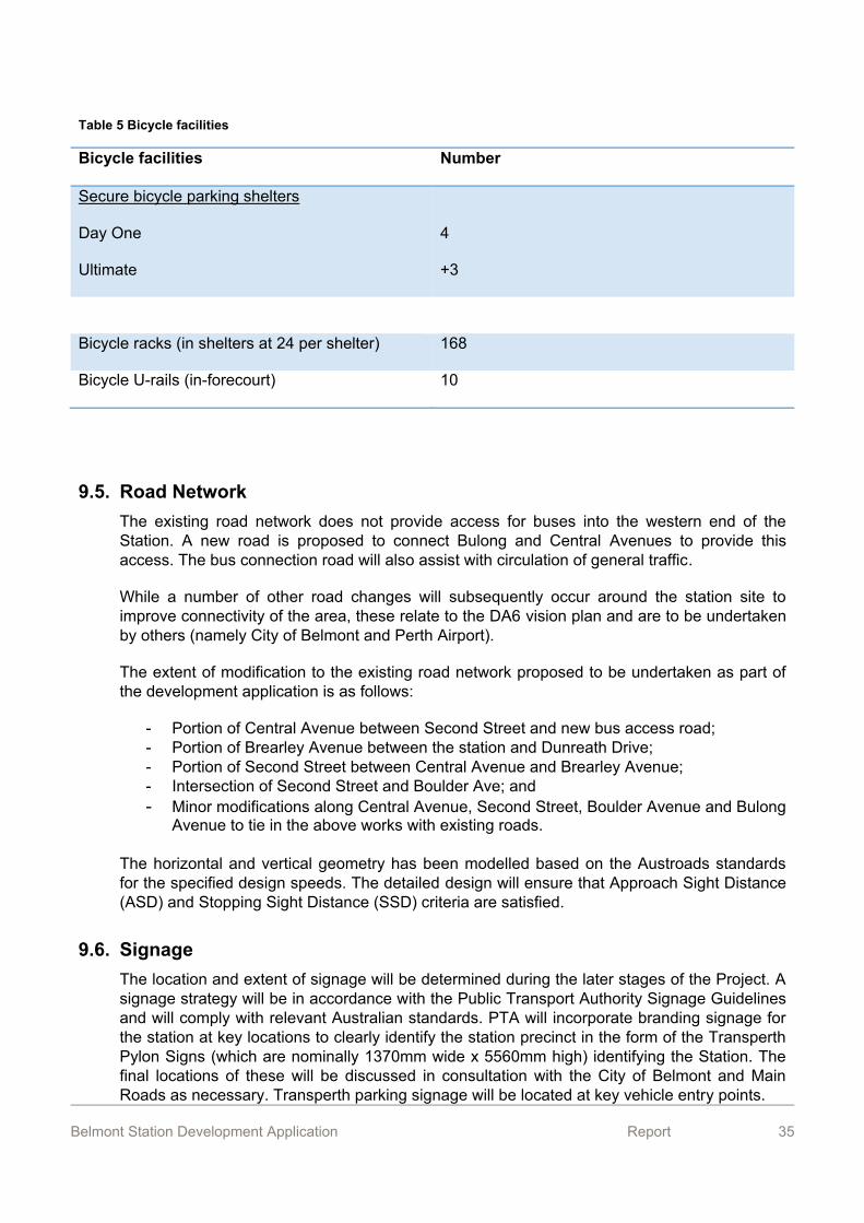
Table 5 below presents bicycles provided at the station.
Belmont Station Development Application Report 35
Table 5 Bicycle facilities
Bicycle facilities Number
Secure bicycle parking shelters
Day One
Ultimate
4
+3
Bicycle racks (in shelters at 24 per shelter) 168
Bicycle U-rails (in-forecourt) 10
9.5. Road Network The existing road network does not provide access for buses into the western end of the Station. A new road is proposed to connect Bulong and Central Avenues to provide this access. The bus connection road will also assist with circulation of general traffic.
While a number of other road changes will subsequently occur around the station site to improve connectivity of the area, these relate to the DA6 vision plan and are to be undertaken by others (namely City of Belmont and Perth Airport).
The extent of modification to the existing road network proposed to be undertaken as part of the development application is as follows:
- Portion of Central Avenue between Second Street and new bus access road; - Portion of Brearley Avenue between the station and Dunreath Drive; - Portion of Second Street between Central Avenue and Brearley Avenue; - Intersection of Second Street and Boulder Ave; and - Minor modifications along Central Avenue, Second Street, Boulder Avenue and Bulong
Avenue to tie in the above works with existing roads.
The horizontal and vertical geometry has been modelled based on the Austroads standards for the specified design speeds. The detailed design will ensure that Approach Sight Distance (ASD) and Stopping Sight Distance (SSD) criteria are satisfied.
9.6. Signage The location and extent of signage will be determined during the later stages of the Project. A signage strategy will be in accordance with the Public Transport Authority Signage Guidelines and will comply with relevant Australian standards. PTA will incorporate branding signage for the station at key locations to clearly identify the station precinct in the form of the Transperth Pylon Signs (which are nominally 1370mm wide x 5560mm high) identifying the Station. The final locations of these will be discussed in consultation with the City of Belmont and Main Roads as necessary. Transperth parking signage will be located at key vehicle entry points.
Belmont Station Development Application Report 36
9.7. Lighting The lighting shall provide a complete solution allowing safe pedestrian movement throughout the station, forecourt area, passenger circulation areas and precinct.
High quality architectural and feature lighting will be provided at the station entrances in a form that is inviting to pedestrians. The entry structures at the station are the main focal point with the surrounding area and must be illuminated to a high level to cater for increased pedestrian activity and complement the entry structure.
For the Belmont Station precinct all street lighting on major local roads will be designed to AS/NZS 1158.1, Road Lighting Category V3 standards and installed in accordance with Western Power and local Authority requirements. Lighting on other minor roads will be designed and installed in accordance with Western Power and Local Authority requirements.
The indicative luminaire and street pole spacing will be approximately 50 m, however, this will be confirmed as part of the detailed design stage The location of new lights will be chosen to suit the location of existing lights, where these can be incorporated into the design. All new or modified street lighting will be designed and installed to suit existing lighting systems and standards.
The car park lighting positions during detailed design will be coordinated with CCTV, street furniture, signage, advertising and planting locations to minimise visual and physical clutter whilst providing a regular and symmetrically repetitive layout. The street lighting positions and planting will also be coordinated to ensure the planting does not impede the lighting coverage.
The Contractor is required to prepare a lighting strategy and incorporate lighting for all stations, Buildings, Station and Building Precincts and Public Domain areas that is in accordance with PTA Technical Specification Document 8803-900-003 – Lighting Design & Maintenance Guidelines.
The lighting design strategy is required to be well-considered, integral and complement the stations, Station and Building Precinct and Public Domain designs.
Belmont Station Development Application Report 37
10. Public Artwork The passenger experience of FAL Stations will be enhanced by the integration of the architecture with art. The JV has selected Maggie Baxter as art curator of the FAL project. Maggie is a prominent Western Australian curator who will bring local and world-class experience to the FAL project and ensure that Art elements are coordinated and integrated within the architecture of Belmont Station. Under Maggie Baxter’s leadership, a Public Artwork Committee, including representatives from the City of Belmont, PTA and SINRW has selected artists Mark Datoti and Steve Tapper to develop artwork for the Project. The artists will develop artwork in collaboration with the Public Art Committee and the design teams in a coordinated effort to match the overall station design intent.

Belmont Station Development Application Report 38
11. Landscaping and Urban Design The station and precinct design undertaken as part of this project coordinates with and reinforces the DA6 Vision Plan. Elements delineated under the project will include permanent works and areas that will form part of the future development sites. It is intended that some public areas will be developed as part of the future development of the precinct.
The landscaping for the Station will create a high level of landscape finish, both soft and hard. An urban landscape will be established within the forecourt and station entrance precincts, with a high quality of hard material finish, furniture and shade trees, activating these urban spaces and providing visual connection to surrounding areas.
The requirements of the landscaping and revegetation works are:
- To ensure that the station is integrated ecologically and visually with the local landscape;
- To enhance the appearance and function of the area for the benefit of the community; and
- To minimise ongoing management costs and future maintenance needs.
Urban design and landscaping of areas within the busway boundary and station forecourt will integrate with Council and Department of Planning.
Belmont Station Development Application Report 39
12. Train Operations Recognising that frequency is a major factor in attracting patronage, a minimum peak hour service of six trains per hour (ten minute intervals) was adopted for the original Joondalup and Mandurah lines. This frequency was also adopted for the extension of the Joondalup Line to Clarkson and the forthcoming extension to Butler. In light of this and as the current peak hour frequency of the Midland to Fremantle service is six trains per hour, it is intended that the frequency from Forrestfield Station will be six trains per hour.
Operating hours will be as for the broader suburban rail service – typically between 5.00am and 12.30am. It is recognised that these operating hours won’t service early morning flight arrivals or departures at Perth airport but commencing services earlier on the overall suburban system is not warranted for the patronage at that time.

Belmont Station Development Application Report 40
13. Bus Operations South Guildford, Belmont, Redcliffe and Cloverdale are the most densely populated suburbs within proximity to the proposed Belmont Station. The revised bus network will improve connectivity and travel time reliability to Perth for residents.
Belmont, Redcliffe and Cloverdale to Belmont Station
The suburbs of Belmont, Redcliffe and Cloverdale are the most extensively served in this area in terms of the current Transperth bus network. Service frequency on many routes is high with the majority of services connecting people directly to the Perth CBD and/or the Armadale, Thornlie or Midland train lines.
It is anticipated that with the introduction of services on the Forrestfield Line a revised bus network will improve connectivity and travel time reliability to Perth for residents, particularly those east of Belmont Forum shopping centre with access to the Forrestfield Line at Belmont Station and to a lesser extent at Airport Central Station.
A new route will provide a frequent and high capacity service along Great Eastern Highway between Belmont Station and Perth. This route will effectively replace the frequency and capacity lost along this activity corridor by redirecting routes to the Forrestfield Line at Forrestfield Station. Services will operate as bi-directional feeders with residents closer to Belmont Station likely to travel backwards to connect with rail for a faster journey to Perth.
Guildford/South Guildford to Belmont Station
Guildford is one of the most well established suburbs that will be served by the proposed Forrestfield Line supporting bus network.
It is anticipated that with the introduction of services on the Forrestfield Line, a revised bus network will significantly improve connectivity and travel time reliability to Perth, as well as facilitate improved “non-Perth” trips to destinations including Belmont City Centre and the Airport. South Guildford residents will, for the first time, be able to travel towards Perth (the main direction of travel) with origin/destination locations at both ends of the bus routes, allowing Transperth to maximise peak period efficiencies.
Current service frequency on Route 304 is less than ideal due to the fact passengers must travel “backwards” to Perth and Midland Station. Given that service frequency has a direct relationship to patronage, Route 304 does not currently perform particularly well, despite the increasing residential development that is occurring in and around the Rosehill Golf Course site. A route extension to Belmont Station, together with upgraded service headways and a more consistent timetable is anticipated to result in an increase in patronage.
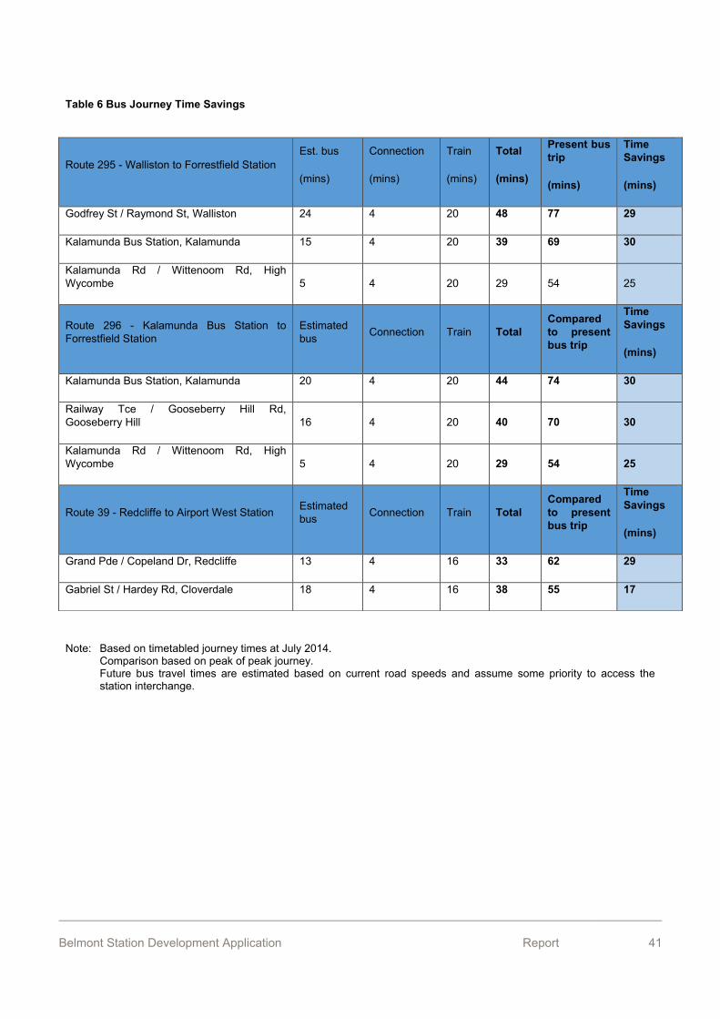
Examples of the savings in journey time resulting from the new bus transfer services are shown in Table 6 below.
Belmont Station Development Application Report 41
Table 6 Bus Journey Time Savings
Note: Based on timetabled journey times at July 2014. Comparison based on peak of peak journey. Future bus travel times are estimated based on current road speeds and assume some priority to access the station interchange.
Route 295 - Walliston to Forrestfield Station Est. bus
(mins)
Connection
(mins)
Train
(mins)
Total
(mins)
Present bus trip
(mins)
Time Savings
(mins)
Godfrey St / Raymond St, Walliston 24 4 20 48 77 29
Kalamunda Bus Station, Kalamunda 15 4 20 39 69 30
Kalamunda Rd / Wittenoom Rd, High Wycombe 5 4 20 29 54 25
Route 296 - Kalamunda Bus Station to Forrestfield Station
Estimated bus Connection Train Total
Compared to present bus trip
Time Savings
(mins)
Kalamunda Bus Station, Kalamunda 20 4 20 44 74 30
Railway Tce / Gooseberry Hill Rd, Gooseberry Hill 16 4 20 40 70 30
Kalamunda Rd / Wittenoom Rd, High Wycombe 5 4 20 29 54 25
Route 39 - Redcliffe to Airport West Station Estimated bus Connection Train Total
Compared to present bus trip
Time Savings
(mins)
Grand Pde / Copeland Dr, Redcliffe 13 4 16 33 62 29
Gabriel St / Hardey Rd, Cloverdale 18 4 16 38 55 17
Belmont Station Development Application Report 42
14. Community Engagement
14.1. Stakeholder engagement The following stakeholders have been consulted during the planning phase of the FAL Project:
Western Australian Planning Commission; City of Belmont; City of Bayswater; Shire of Kalamunda; Department of Infrastructure and Regional Development (Federal); Department of the Environment (Federal); Environmental Protection Authority; Office of the Environmental Protection Authority; Department of Environment Regulation; Department of Lands; Department of Mining and Petroleum; Department of Health; Department of Water; Department of Aboriginal Affairs; Department of Premier and Cabinet; Department of Fire and Emergency Services; South West Aboriginal Land and Sea Council; Whadjuk Working Group and other interested Aboriginal elders; Department of Parks and Wildlife; Swan River Trust; Office of Government Architect; Perth Airport Pty Ltd; Main Roads WA; Western Power; and DBP Transmission. Belmont Station Community Reference Group FAL Access and Inclusion Working Group
In addition, discussions have been held with Brookfield Rail and Aurizon with respect to any potential impacts the Project may have upon their assets and/or operations along the nearby freight rail corridor, with the PTA entering into separate commercial agreements with both entities.
Belmont Station Development Application Report 43
14.2. Community engagement Understanding that the Belmont Station Precinct development will be of significant interest to the local community, the PTA has undertaken substantial community consultation across the Belmont Community Zone in preparation for its construction.
In addition, the Contractor is implementing a comprehensive community engagement program. The details of this program are set out in the Stakeholder and Community Engagement Action Plan.
14.3. Stakeholder and Community Engagement Action Plan The Contractor has developed a Stakeholder and Community Engagement Action Plan (SCEAP) which describes the strategies, processes and implementation for engaging with FAL project stakeholders and the community.
The SCEAP is a practical, implementable and auditable tool, designed to facilitate community and stakeholder engagement and the timely flow of information during the construction delivery stages of the FAL project.
During the planning stage of the FAL project, the project team engaged collaboratively with key stakeholders and their involvement has directly influenced the final designs and delivery strategies for the Project.
The most effective way of managing potential impacts associated with construction activities is through clear, concise, timely and truthful communication of the intended works and the potential impacts. The Contractor will ensure that stakeholders and the community receive concise, factual, jargon-free and current information regarding construction activities. All communications material will take into account the needs of people with a disability. Communication materials and activities may include, but are not limited to:
Belmont Station Community Group – established October 2016, nine members meet monthly or as required with representatives from the project team;
Belmont Community Information Sessions – held regularly to provide information about key construction activities and an opportunity for members of the community to meet the construction team and discuss any concerns;
Face-to-face meetings with residents and businesses to quickly resolve any concerns raised;
Fact sheets on topics covering major elements of the Project construction, which will be updated at six monthly intervals (or as required);
Construction work notifications for specific work activities which will directly impact stakeholders, residences and businesses;
Display material will generate interest and inform the community of construction activities and will be updated as construction progresses;
Signage will be undertaken in accordance with the relevant planning approval conditions and in consultation with relevant contractors / consultants;
Photography, which may include stills, aerial, digital video footage and time lapse showing the progression of construction activities;

Belmont Station Development Application Report 44
3D animations for educational purposes regarding construction methods, milestones, stations and other significant infrastructure associated with the Project;
Project advertising will be undertaken at regular intervals to communicate any disruptions to the general public including service disruptions to rail, bus or road networks;
Formal presentations to stakeholders and the public; Project website updates will be undertaken regularly; Project social media channels updated regularly to show project progress; Communication Action Plans will be developed, as required for major pieces of
construction work, during the Project delivery; and News stories will be prepared once a month for inclusion in the regular stakeholder
and community project updates.
The management of the construction impacts will be a team effort with the Contractor working collaboratively to minimise and manage risk to residents and businesses in the construction zone, responding quickly to all incidents and complaints.
14.4. Enquiries, Complaints and Commendations A 1800 telephone number (1800 814 512) and dedicated email address ([email protected]) have been established to receive enquiries and complaints related to construction. The phone is manned during normal construction hours of 7am to 7pm weekdays and 9am to 5pm weekends. A separate site office phone number will be established for out-of-hours emergency calls and night works.
Consultation Manager is the database management system used to record stakeholder and community enquiries, complaints and commendations. This database is managed and maintained by both the Contractor and the PTA communications teams to ensure a seamless approach to managing any complaints or enquiries.
Belmont Station Development Application Report 45
15. Planning Justification 15.1. Land Use and Development
15.1.1 State and Metropolitan Policies
The proposed Belmont station is one of three stations on the Forrestfield-Airport Link, a $2billion major State Government project that will meet key transport and growth objectives outlined in various State and metropolitan planning strategies/policies.
State Planning Strategy 2050
The Project is a major government initiative consistent with the key transport objective of the State Planning Strategy 2050, being “to manage the movement of people, goods and services through an integrated network connected locally, regionally, nationally and globally.” The Strategy promotes connecting communities, “while improving efficiency, reducing travel times and encouraging a modal shift towards lower-impact transport options.” The Strategy identifies a need for significant investment in public transport infrastructure and improvements to support its “crucial role in reducing congestion.” The Project meets these transport objectives.
Directions 2031
The Project is consistent with the vision of Directions 2031, a spatial framework based on the three integrated networks of: activity centre networks; movement networks; and green networks. Perth Airport is identified in the strategy as a ‘specialised centre’. The draft Central Metropolitan Perth Sub-Regional Strategy, released in 2010 to expand on the vision of Directions 2031, identified a rail spur to Perth Airport from the Midland line as a potential public transport project.
The Project is a key initiative in meeting the Directions 2031 objective of “an integrated system of public and private transport networks that are designed to support and reinforce the activity centres network.” In particular, it will be a significant project in meeting and supporting the strategic theme for an ‘accessible city’, which includes the following objectives:
- connect communities with jobs and services; - improve the efficiency and effectiveness of public transport; - encourage a shift to more sustainable transport modes; - maximise the efficiency of road infrastructure; - manage and reduce congestion; - protect freight networks and the movement economy; - consider parking in the overall transport picture; - plan and develop urban corridors to accommodate medium-rise, higher density
housing development; - plan and develop transit oriented developments to accommodate mixed use and
higher density housing development.
Draft Perth and Peel @3.5million and Central Sub-Regional Planning Framework
Belmont Station Development Application Report 46
In May 2015, the WA Planning Commission released the draft Perth and Peel @3.5million report and associated sub-regional planning frameworks for comment. These strategic documents further identify how the vision set out in Directions 2031 for a city of 3.5 million by 2050 can be realised.
The Project addresses a number of the challenges identified in the draft strategy, including:
- improving current density infill and managing further greenfield development; - achieving a connected city growth pattern; - reducing car dependency; - maintaining liveability.
The draft strategy identifies a range of transport strategies to reduce car dependency and alleviate road congestion, including:
- improve integration of transport within activity centres; - investigate transport options, including new routes and technology; - provide movement network improvements including upgrades and extensions of
road, rail and transit priority routes.
The Project is a key initiative in meeting the objective for a ‘connected city’, in particular the aspiration of “improving the public transport connectivity of employment centres and urban consolidation areas and actively encourage non-motorised transport and vehicle sharing.” Within the Central sub-region, the Project is identified in the draft framework as a future passenger rail route.
In conjunction with the City of Belmont’s structure planning for Development Area 6 (refer below), the Project meets the objective of increasing urban consolidation and infill housing within an established area.
State Planning Policy No. 3: Urban Growth and Settlement
This policy aims “to facilitate sustainable patterns of urban growth and settlement” throughout Western Australia. The Project is consistent with the objective of promoting sustainable and liveable neighbourhoods that reduce energy and travel demands, “whilst ensuring safe and convenient access to employment and services by all modes”.
The policy identifies a key element of managing growth in Metropolitan Perth as “developing an integrated land use and transport network which reduces car dependence and broadens travel options, makes it easier for people to use public transport or walk or cycle to their destinations, and establishes defined transport corridors as the major network for the movement of goods and people”. The Project will make a significant contribution to meeting this aspiration. The Project will also be a catalyst for the consolidation of residential development in established areas, based on transit oriented development principles, as promoted by the policy.
State Planning Policy 5.1: Land Use Planning In The Vicinity Of Perth Airport
The objectives of this policy are to:
Belmont Station Development Application Report 47
- protect Perth Airport from unreasonable encroachment by incompatible (noise sensitive) development, to provide for its ongoing development and operation; and
- minimise the impact of airport operations on existing and future communities with reference to aircraft noise.
The City of Belmont Local Planning Scheme No. 15 zoning map indicates the 20 Australian Noise Exposure Forecast (ANEF) contour encroaches into the eastern portion of the development precinct. The proposed station, however, is not considered a sensitive use that would be unduly impacted by aircraft noise.
State Planning Policy 5.4: Road and Rail Transport Noise and Freight Considerations in Land Use Planning
Existing noise and vibration levels have been measured to obtain baseline data of ambient conditions at the at each station location. The Project has agreed noise and vibration limits for train operations with the Department of Environment Regulation (DER) noise branch. These have been developed to comply with the State Planning Policy 5.4, Road and Rail Transport Noise and Freight Considerations in Land Use Planning, and takes guidance from current industry standards where criteria in addition to those provided in State Planning Policy 5.4 are deemed appropriate.
Construction noise will be managed to comply with the Environmental Protection (Noise) Regulations 1997.
The detailed design of track, plant and station facilities is required to comply with the noise and vibration criteria that have been agreed with the DER. Full details are contained in Forrestfield-Airport Link Noise and Vibration Management Construction and Operation Environment Impact Report, SLR February 2015.
Draft State Planning Policy 7: Design of the Built Environment
This policy was released in October 2016 as a draft for public comment. The policy “addresses the design quality of the built environment across all planning and development types, in order to deliver broad economic, environmental, social and cultural benefit.”
The proposed Belmont Station responds to the 10 design principles identified in the policy, as follows:
1. Context and character
The proposed development will enhance the existing characteristics of the subject land and immediate surrounds. The development will make a positive contribution to the future character of the area promoted by the City of Belmont’s Vision Plan for Development Area 6, in particular as the catalyst for Transit Oriented Development. The station forecourt will provide a new civic address for the locality, with the opportunity of engaging the wider community. The new entrance will be an activated area where people will gather, enabling the City of Belmont to create a vibrant new urban precinct. 2. Landscape quality
The location of Belmont Station provides an opportunity to create landscape themes inspired by the natural Perth landscape setting. Landscaping will be integrated with built form and
Belmont Station Development Application Report 48
urban design elements, with a mix of hard and soft landscape components. Landscaping will include low maintenance and waterwise planting, and will incorporate aspects of Wildflower Way and State Government Landscape Initiative. The proposed design aims to incorporate mature trees and existing vegetation to benefit the precinct and site character, in particular in early stages. 3. Built form and scale
The proposed built form reflects the civic nature of the transport facility and provides a high quality public realm with a good pedestrian environment. The massing and height is appropriate to its setting and the anticipated future character of the City of Belmont’s Vision Plan for Development Area 6. The most prominent feature of the design is the roof shape and the north-south link which connects Bulong Avenue and Central Avenue. The station entries are designed as open ‘piazza’ where the passengers flow without physical and visual interruptions through the fair gates, which will allow passengers to look down over the platform level below. The dynamic and directional roof form enhances the creation of the prominent entrance, visible from the surrounding areas.
4. Functionality and build quality
The proposed development is specifically designed as a bus/rail interchange transport facility to meet the needs of all users, including passengers and PTA staff. The train station will be well integrated with the adjacent bus interchange, bicycle facilities and car parking areas. Building materials will be durable and robust, including precast concrete wall panels and anti-graffiti measures. The station will create simple, elegant and aesthetically pleasant spaces and experiences using high quality and consistent materials, finishes and detailing, providing spaces that are cohesive, welcoming and attractive. The major building elements of the station have been selected to minimise maintenance and achieve durability. 5. Sustainability
The proposed development incorporates various sustainability elements, with the aim being for it to be a low carbon, and low waste station. The station design intends to minimise energy with emphasis on natural daylight, natural cross ventilation and LED lighting throughout. The main sustainable design features will include an efficient structure that can provide the required design life in terms of quality, maintainability, and future flexibility. Belmont Station will include insulated roof canopies to minimise direct solar gain with daylight admitted as a central spine of light modified by frosted layers on the inner plane. Roof planes incline upward to release trapped heated air. A selection of recycled materials will play an integral part in assessing the sustainability of the design solution. Water usage reduction features will also be incorporated,
6. Amenity
The passenger experience is integral to the design of the station precinct. The design of the station optimises internal amenity for users, including by providing clear views of the platforms for passengers and transit guards, and by providing good levels of natural light and natural ventilation. The proposed development is universally accessible and provides weather protection to external spaces. The subject land is sufficiently separated from surrounding properties to ensure there are minimal or no adverse amenity impacts.
7. Legibility
Belmont Station Development Application Report 49
Legibility is a key consideration in the design of the Belmont Station precinct. The proposed station design integrates with the street network, directing pedestrian traffic up to the main street in the future Town Centre. A civic square provides a clear address for the station, and a plaza function as a forecourt and gathering place for future development. The design considers priority to pedestrians and cyclists in all planning and detailed design of the station and precinct areas, in accordance with PTA operational requirements. Pedestrians will have permeability throughout the station precinct with comprehensive pathways to the station entry points from the south and north area. Cyclists will have benefit from a safe cycle route from the catchment area, into and through the station precinct. The modal hierarchy will be designed with pavement materials selection to ensure safe intermodal function. The placement of hard surfaces will assist in identifying shared use across user conflict points e.g. pedestrian crossings at bus lanes and primary shared paths. A comprehensive wayfinding and signage strategy will ensure passengers and other users move efficiently through the station and surrounds. 8. Safety
The design has regard for the WA Planning Commission’s Designing Out Crime Planning Guidelines. The following principles of Crime Prevention Through Environmental Design (CPTED) are incorporated into the proposed development:
- natural surveillance;
- urban structure;
- activity generators;
- building design;
- lighting;
- sightlines and wayfinding;
- signage;
- predictable routes and spaces safe from entrapment;
- public toilets; and
- pedestrian overpasses and lifts.
9. Community
The Belmont Station precinct will be an important public transport facility for the local and regional communities, supporting a diverse range of people and facilitating social interaction. The station forecourt will serve as a civic square and gathering space that provides an opportunity for community events. Public art will be integrated into the development.
10. Aesthetics
The creative station design results in an attractive, interesting and inviting building that reflects its civic function. The iconic roof form and north-south link/entries provide a welcoming entrance that is visible from a distance, and the distinctive architecture will be highly recognisable.
Development Control Policy 1.6: Planning to Support Transit Use and Transit Oriented Development
Belmont Station Development Application Report 50
Development Control Policy 1.6 promotes planning and development outcomes that support and sustain public transport use, and achieve the more effective integration of land use and public transport. The policy applies to proposals for development or redevelopment with transit oriented precincts and to proposals for new transit facilities.
The proposed Belmont station and associated works meets the objectives and requirements of the Development Control Policy 1.6, as follows:
- the station will be of a scale and character that suits its surrounds, both in respect to existing development and the vision for the future of Development Area 6;
- the station will provide a high standard of amenity for transit users; - the proposal will facilitate modal shift by encouraging increased public transport use,
which will be highly accessible for pedestrian and cyclists; - the station and surrounds will reflect the civic nature of the transit function, contribute
to the quality of the public realm, and be highly legible in its setting; - as the rail line will be underground, severance effects will be minimal, and most likely
an improvement on the existing Brearley Avenue environment.
15.1.2 Metropolitan Region Scheme
The proposed use and development are consistent with the ‘Urban’ zoning of the land under the MRS. It is intended the MRS will soon be amended to reflect the ultimate use and development of the land affected by the Project.
15.1.3 City of Belmont Local Planning Scheme No. 15 and Local Policies/Strategies
Pursuant to the provisions of the Planning and Development Act 2005, the public works are exempt from approval under the local planning scheme.
The Belmont Station is a key element of the Vision Plan for the City of Belmont’s Development Area 6 contained in Local Planning Policy No. 14..The proposed station will be a catalyst for infill housing through increased residential densities and transit oriented development in this area, consistent with State and local planning objectives. As such, the proposal is consistent with the City of Belmont’s planning and development objectives for the Development Area 6.
Draft Perth and Peel @3.5million
In May 2015, the WA Planning Commission released the draft Perth and Peel @3.5million report and associated sub-regional planning frameworks for comment. These strategic documents further identify how the vision set out in Directions 2031 for a city of 3.5 million by 2050 can be realised.
The Project addresses a number of the challenges identified in the draft strategy, including:
improving current density infill and managing further greenfield development; achieving a connected city growth pattern; reducing car dependency; and maintaining liveability.
Belmont Station Development Application Report 51
The draft strategy identifies a range of transport strategies to reduce car dependency and alleviate road congestion, including:
improve integration of transport within activity centres; investigate transport options, including new routes and technology; and provide movement network improvements including upgrades and extensions of road, rail
and transit priority routes.
The Project is a key initiative in meeting the objective for a ‘connected city’, in particular the aspiration of “improving the public transport connectivity of employment centres and urban consolidation areas and actively encourage non-motorised transport and vehicle sharing.” Within the Central sub-region, the Project is identified in the draft framework as a future passenger rail route.
Transport @ 3.5 million – Perth and Peel Transport Plan for 3.5 million People and Beyond
In July 2016, the Transport Portfolio released the draft Transport @ 3.5 million plan for public consultation. The plan was finalised in February 2017. Transport @ 3.5 Million is modelled on the Western Australian Planning Commission’s draft Perth and Peel @ 3.5 Million planning frameworks of where people will live and work. It also aligns with the Perth and Peel Green Growth Plan for 3.5 Million
The State Government has developed a vision for Perth's future transport network; designed to keep our city moving as we grow and help Perth to continue to be one of the most liveable cities in the world.
It provides a long term plan for transport infrastructure and considers how we can use the transport network more efficiently as Perth's population approaches 3.5 million and beyond. The plan looks at where people will live and work when the population reaches 3.5 million and outlines a flexible transport system so that people and freight can keep moving as the city grows.
The project is identified in the plan as being required by the time Perth’s metropolitan population reaches 2.7 million. The supporting bus feeder network and provision of Park ‘n’ Ride bays between Belmont and Forrestfield Stations will extend the effective reach of the rail network to the eastern suburbs, from Belmont to Kalamunda. The line will also effectively provide extra rail services from Bayswater, relieving capacity issues in the inner core of the Midland and Fremantle lines.
15.2. Environmental Management The environmental setting of the Project has been established through a number of detailed studies inclusive of flora, fauna and vegetation, acid sulphate soils (ASS), contaminated sites, dewatering, noise and vibration and Aboriginal heritage. The outcomes of these studies informed the Project’s environmental approval and the associated Environmental Impact Assessment.
Belmont Station Development Application Report 52
Due to its significant impacts to flora and vegetation the project has applied for and received environmental approval from the Western Australian Minister for Environment. Environmental approval from the Commonwealth Minister for the Environment is not required as there are no Matters of National Environmental Significance which will or could be affected by the project.
Aside from the impacts to flora and vegetation, the State Environmental Protection Agency (EPA) considers that the project’s environmental impacts are not significant and can be managed under existing legislation, policy and guidelines. A summary of the potential environmental impacts and the proposed environmental management framework is provided in Table 7 below.
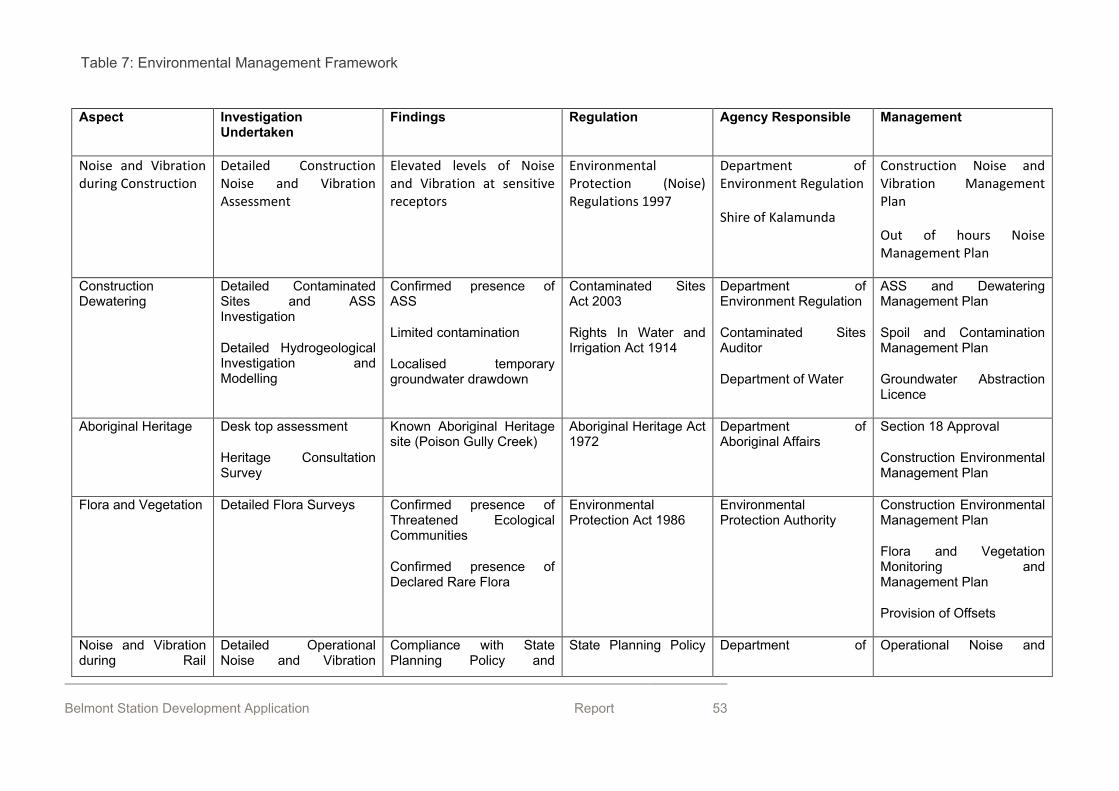
Belmont Station Development Application Report 53
Aspect Investigation Undertaken
Findings Regulation Agency Responsible Management
Noise and Vibration during Construction
Detailed Construction Noise and Vibration Assessment
Elevated levels of Noise and Vibration at sensitive receptors
Environmental Protection (Noise) Regulations 1997
Department of Environment Regulation
Shire of Kalamunda
Construction Noise and Vibration Management Plan
Out of hours Noise Management Plan
Construction Dewatering
Detailed Contaminated Sites and ASS Investigation
Detailed Hydrogeological Investigation and Modelling
Confirmed presence of ASS
Limited contamination
Localised temporary groundwater drawdown
Contaminated Sites Act 2003
Rights In Water and Irrigation Act 1914
Department of Environment Regulation
Contaminated Sites Auditor
Department of Water
ASS and Dewatering Management Plan
Spoil and Contamination Management Plan
Groundwater Abstraction Licence
Aboriginal Heritage Desk top assessment
Heritage Consultation Survey
Known Aboriginal Heritage site (Poison Gully Creek)
Aboriginal Heritage Act 1972
Department of Aboriginal Affairs
Section 18 Approval
Construction Environmental Management Plan
Flora and Vegetation Detailed Flora Surveys Confirmed presence of Threatened Ecological Communities
Confirmed presence of Declared Rare Flora
Environmental Protection Act 1986
Environmental Protection Authority
Construction Environmental Management Plan
Flora and Vegetation Monitoring and Management Plan
Provision of Offsets
Noise and Vibration during Rail
Detailed Operational Noise and Vibration
Compliance with State Planning Policy and
State Planning Policy Department of Operational Noise and
Table 7: Environmental Management Framework
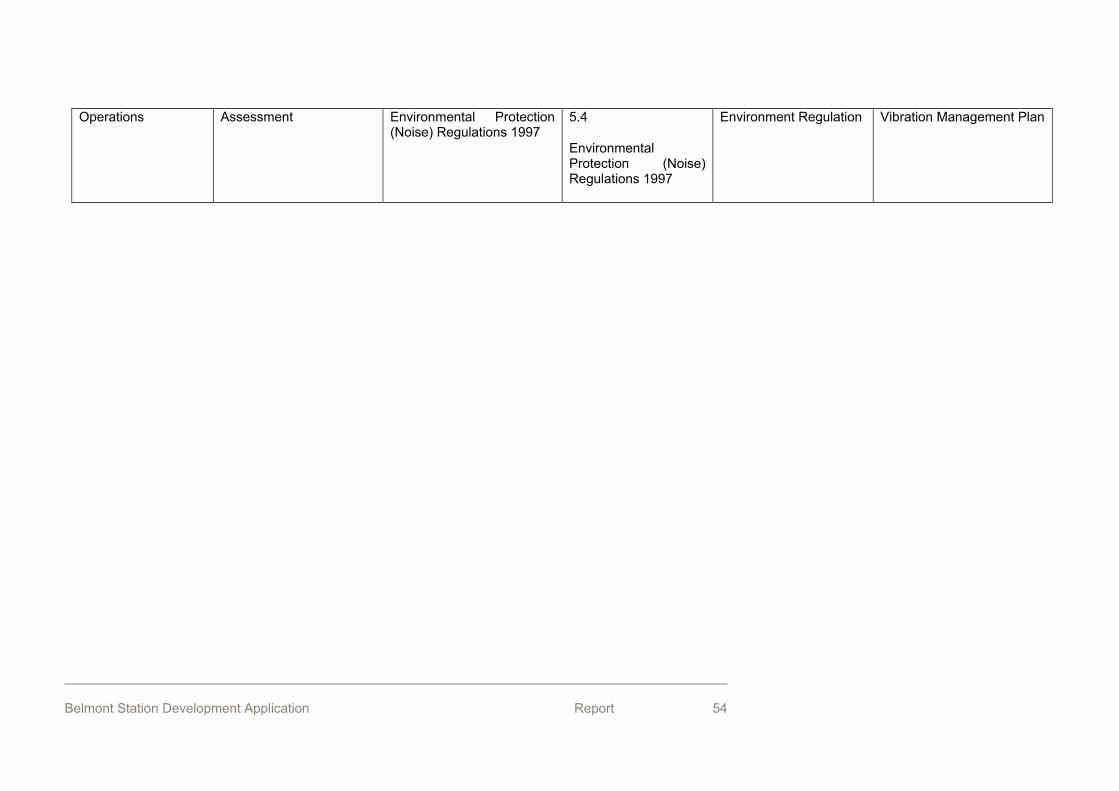
Belmont Station Development Application Report 54
Operations Assessment Environmental Protection (Noise) Regulations 1997
5.4
Environmental Protection (Noise) Regulations 1997
Environment Regulation Vibration Management Plan
Belmont Station Development Application Report 55
16. Conclusion The PTA requests the WAPC’s in principle approval for the concept design for the future Belmont Station and associated works. The Forrestfield-Airport Link is a $2billion State government project that meets various planning objectives in related to transport and urban consolidation. The proposal is also integral to the City of Belmont’s DA6 Vision Plan.
Belmont Station Development Application Report 56
Appendix 1: Belmont Station Drawings
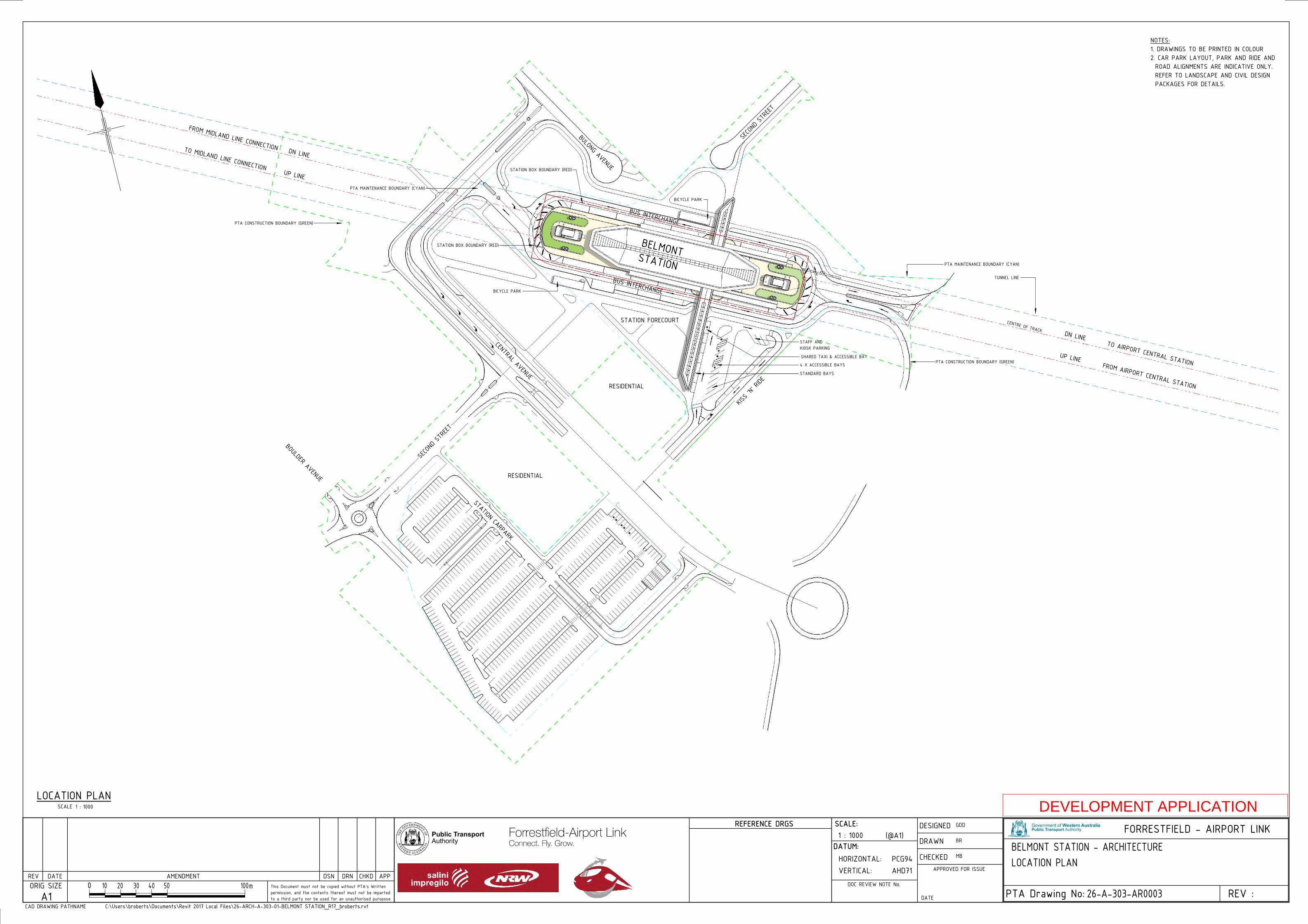
BUS INTERCHANGE
BUS INTERCHANGE
STATION FORECOURT
KISS 'N' RIDE
BULONG AVENUE
CENTRAL AVENUE
SECOND STREET
BOULDER AVENUE RESIDENTIAL
RESIDENTIAL
BELMONT STATION
PTA CONSTRUCTION BOUNDARY (GREEN)
PTA MAINTENANCE BOUNDARY (CYAN)
PTA CONSTRUCTION BOUNDARY (GREEN)
PTA MAINTENANCE BOUNDARY (CYAN)
STATION BOX BOUNDARY (RED)
STATION BOX BOUNDARY (RED)
SECOND STREET
STAFF AND KIOSK PARKING
DN LINE
UP LINEFROM AIRPORT CENTRAL STATION
TO AIRPORT CENTRAL STATION
DN LINE
UP LINE
TO MIDLAND LINE CONNECTION
FROM MIDLAND LINE CONNECTION
STATION CARPARK
4 X ACCESSIBLE BAYS
STANDARD BAYS
SHARED TAXI & ACCESSIBLE BAY
BICYCLE PARK
BICYCLE PARK
TUNNEL LINE
CENTRE OF TRACK
0REV :
FORRESTFIELD - AIRPORT LINK
PTA Drawing No:
(@A1)
ORIG SIZEA1
REV DATE AMENDMENT DRN CHKD APP
CAD DRAWING PATHNAME
SCALE:
VERTICAL:HORIZONTAL:
DATUM:
AHD71PCG94
DOC REVIEW NOTE No.10 20 30 40 50 m100
REFERENCE DRGS
DSNThis Document must not be copied without PTA's Written permission, and the contents thereof must not be imparted to a third party nor be used for an unauthorised puropose
APPROVED FOR ISSUE
CHECKED
DRAWN
DESIGNED
DATEC:\Users\broberts\Documents\Revit 2017 Local Files\26-ARCH-A-303-01-BELMONT STATION_R17_broberts.rvt
1 : 1000
26-A-303-AR0003
GDD
BR
MBBELMONT STATION - ARCHITECTURELOCATION PLAN
NOTES:1. DRAWINGS TO BE PRINTED IN COLOUR2. CAR PARK LAYOUT, PARK AND RIDE AND ROAD ALIGNMENTS ARE INDICATIVE ONLY. REFER TO LANDSCAPE AND CIVIL DESIGN PACKAGES FOR DETAILS.
SCALE 1 : 1000LOCATION PLAN
DEVELOPMENT APPLICATION
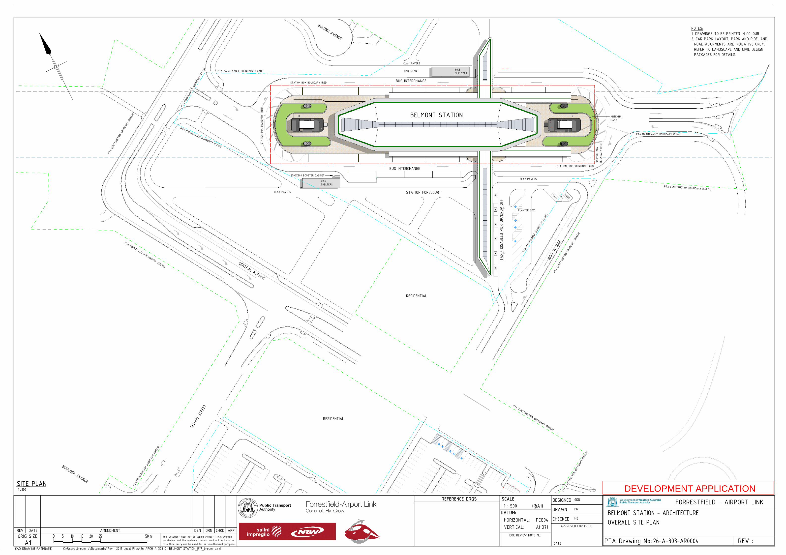
TAXI/
DISA
BLED
PICK-
UP/D
ROP
OFF
BUS INTERCHANGE
BUS INTERCHANGE
STATION FORECOURT
BIKE SHELTERS
BIKE SHELTERS
KISS
'N' R
IDE
BULONG AVENUE
CENTRAL AVENUE
SECO
ND STR
EET
BOULDER AVENUE
RESIDENTIAL
RESIDENTIAL
BELMONT STATION
PTA MAINTENANCE BOUNDARY (CYAN)
PTA CONSTRUCTION BOUNDARY (GREEN)
PTA
CONS
TRUC
TION
BOUN
DARY
(GRE
EN)
PTA
MAINT
ENAN
CE B
OUND
ARY
(CYAN
)
PLANTER BOX
CLAY PAVERS
HARDSTAND
2000X800 BOOSTER CABINET
PTA
MAINT
ENAN
CE BOU
NDAR
Y (CY
AN)
PTA
CONS
TRUC
TION
BOUN
DARY
(GRE
EN)
STATION BOX BOUNDARY (RED)
STAT
ION
BOX
BOUN
DARY
(RE
D)
STAT
ION
BOX
BOUN
DARY
(RE
D)
STATION BOX BOUNDARY (RED)
PTA MAINTENANCE BOUNDARY (CYAN)
PTA CONSTRUCTION BOUNDARY (GREEN)
PTA
CONS
TRUC
TION BO
UNDA
RY (G
REEN
)
PTA CONSTRUCTION BOUNDARY (GREEN)
PTA
CONS
TRUC
TION
BOUN
DARY
(GRE
EN)
PTA MAINTENANCE BOUNDARY (CYAN)
ANTENNA MAST
CLAY PAVERS
CLAY PAVERS
STAFFKIOSK
STAFF
0REV :
FORRESTFIELD - AIRPORT LINK
PTA Drawing No:
(@A1)
ORIG SIZEA1
REV DATE AMENDMENT DRN CHKD APP
CAD DRAWING PATHNAME
SCALE:
VERTICAL:HORIZONTAL:
DATUM:
AHD71PCG94
DOC REVIEW NOTE No.5 10 15 20 25 m50
REFERENCE DRGS
DSNThis Document must not be copied without PTA's Written permission, and the contents thereof must not be imparted to a third party nor be used for an unauthorised puropose
APPROVED FOR ISSUE
CHECKED
DRAWN
DESIGNED
DATEC:\Users\broberts\Documents\Revit 2017 Local Files\26-ARCH-A-303-01-BELMONT STATION_R17_broberts.rvt
1 : 500
26-A-303-AR0004
GDD
BR
MBBELMONT STATION - ARCHITECTUREOVERALL SITE PLAN
1 : 500SITE PLAN
NOTES:1. DRAWINGS TO BE PRINTED IN COLOUR2. CAR PARK LAYOUT, PARK AND RIDE, AND ROAD ALIGNMENTS ARE INDICATIVE ONLY. REFER TO LANDSCAPE AND CIVIL DESIGN PACKAGES FOR DETAILS.
DEVELOPMENT APPLICATION
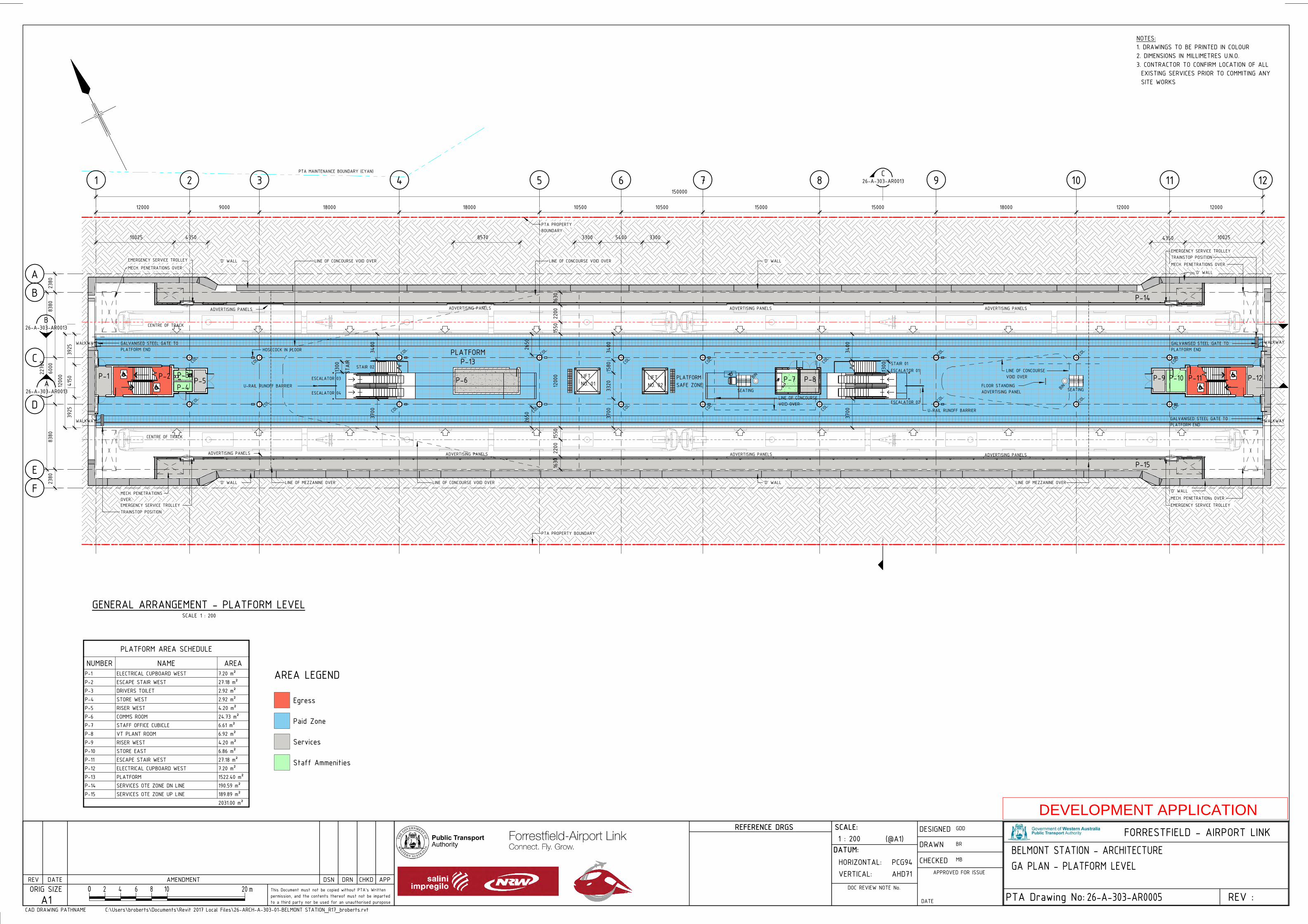
1 2 3 4 5 6 7 8 9 10 11 12
B
C
E
B26-A-303-AR0013
C26-A-303-AR0013
D
A26-A-303-AR0013
A
F
PLATFORM3925
4150
3925
COL.
COL.
COL.
COL.
COL.
LIFT NO. 02
LIFT NO. 01
BIN
SEATING SEATING
ADVERTISING PANELS ADVERTISING PANELS ADVERTISING PANELS ADVERTISING PANELS
ADVERTISING PANELS ADVERTISING PANELS ADVERTISING PANELS ADVERTISING PANELS
1200
0
LINE OF CONCOURSE VOID OVER
LINE OF MEZZANINE OVER
'D' WALL
'D' WALL
'D' WALL
'D' WALL
'D' WALL
EMERGENCY SERVICE TROLLEY
'D' WALL
LINE OF CONCOURSE VOID OVER
LINE OF CONCOURSE VOID OVER
GALVANISED STEEL GATE TO PLATFORM END
GALVANISED STEEL GATE TO PLATFORM END
12000 9000 18000 18000 10500 10500 15000 15000 18000 12000 12000
2380
8380
6000
8380
2380
GALVANISED STEEL GATE TO PLATFORM END
PLATFORM SAFE ZONE
ESCALATOR 01
ESCALATOR 02
STAIR 02
COL.
COL.
COL. CO
L. CO
L.
COL.
COL.
COL.
COL.
COL.
COL.
COL.
COL.
COL.
COL.
LINE OF CONCOURSE VOID OVER
BIN
EMERGENCY SERVICE TROLLEY
EMERGENCY SERVICE TROLLEY
TRAINSTOP POSITION
TRAINSTOP POSITION
2276
0
LINE OF CONCOURSE VOID OVER
WALKWAY
WALKWAY WALKWAY
WALKWAY
MECH. PENETRATIONS OVER.
MECH. PENETRATIONs OVER
MECH. PENETRATIONS OVER
MECH. PENETRATIONS OVER
PTA PROPERTY BOUNDARY
PTA PROPERTY BOUNDARY
U-RAIL RUNOFF BARRIER
CENTRE OF TRACK
CENTRE OF TRACK
FLOOR STANDING ADVERTISING PANEL
EMERGENCY SERVICE TROLLEY
1630
2200
1550
1200
015
5022
0016
30
3300 5400 330010025 4350 4350 100258570
3400
1580
3320
3700
HOSECOCK IN FLOOR
LINE OF MEZZANINE OVER
PTA MAINTENANCE BOUNDARY (CYAN)
P-1 P-2P-4P-3
P-5
P-13
P-6 P-7 P-8 P-9 P-10 P-11 P-12
P-14
P-15
STAIR
1300
AREA LEGEND
Egress
Paid Zone
Services
Staff Ammenities
150000
U-RAIL RUNOFF BARRIER ESCALATOR 03
ESCALATOR 04
STAIR 01
3400
3700
2650
2650
1300
3400
3700
0REV :
FORRESTFIELD - AIRPORT LINK
PTA Drawing No:
(@A1)
ORIG SIZEA1
REV DATE AMENDMENT DRN CHKD APP
CAD DRAWING PATHNAME
SCALE:
VERTICAL:HORIZONTAL:
DATUM:
AHD71PCG94
DOC REVIEW NOTE No.2 4 6 8 10 m20
REFERENCE DRGS
DSNThis Document must not be copied without PTA's Written permission, and the contents thereof must not be imparted to a third party nor be used for an unauthorised puropose
APPROVED FOR ISSUE
CHECKED
DRAWN
DESIGNED
DATEC:\Users\broberts\Documents\Revit 2017 Local Files\26-ARCH-A-303-01-BELMONT STATION_R17_broberts.rvt
1 : 200
26-A-303-AR0005
GDD
BR
MBBELMONT STATION - ARCHITECTUREGA PLAN - PLATFORM LEVEL
NOTES:1. DRAWINGS TO BE PRINTED IN COLOUR2. DIMENSIONS IN MILLIMETRES U.N.O.3. CONTRACTOR TO CONFIRM LOCATION OF ALL EXISTING SERVICES PRIOR TO COMMITING ANY SITE WORKS
SCALE 1 : 200GENERAL ARRANGEMENT - PLATFORM LEVEL
PLATFORM AREA SCHEDULE
NUMBER NAME AREAP-1 ELECTRICAL CUPBOARD WEST 7.20 m²P-2 ESCAPE STAIR WEST 27.18 m²P-3 DRIVERS TOILET 2.92 m²P-4 STORE WEST 2.92 m²P-5 RISER WEST 4.20 m²P-6 COMMS ROOM 24.73 m²P-7 STAFF OFFICE CUBICLE 6.61 m²P-8 VT PLANT ROOM 6.92 m²P-9 RISER WEST 4.20 m²P-10 STORE EAST 6.86 m²P-11 ESCAPE STAIR WEST 27.18 m²P-12 ELECTRICAL CUPBOARD WEST 7.20 m²P-13 PLATFORM 1522.40 m²P-14 SERVICES OTE ZONE DN LINE 190.59 m²P-15 SERVICES OTE ZONE UP LINE 189.89 m²
2031.00 m²
DEVELOPMENT APPLICATION
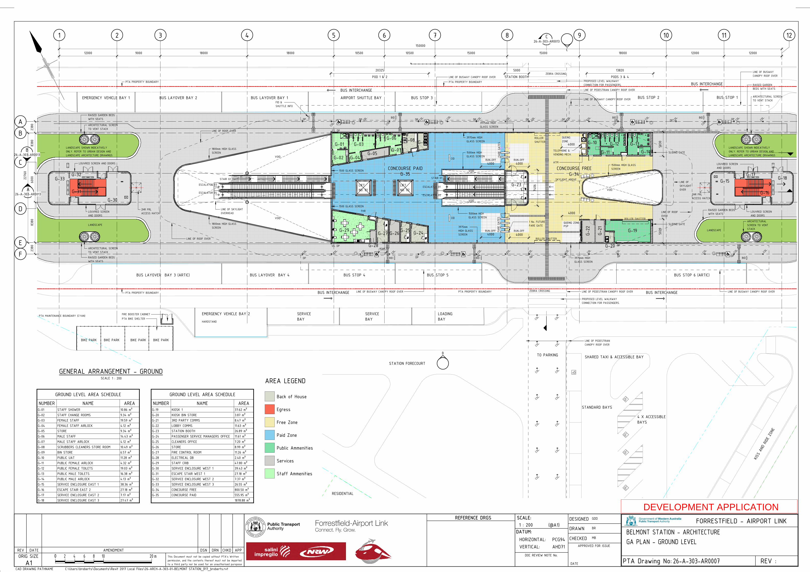
D
C
1 2 3 4 5 6 7 8 9 10 11 12
B
C
E
B26-A-303-AR0013
C26-A-303-AR0013
D
A26-A-303-AR0013
A
F
CONCOURSE FREE
G-21
G-22 G-19
G-23
G-29
12000 9000 18000 18000 10500 10500 15000 15000 18000 12000 12000
ATM
G-30
G-31
VOID
ESCALATOR 01
ESCALATOR 02
VOID
FARE
GAT
ESFA
RE G
ATES
ROLLER SHUTTER
PSPQUEING ZONE
VOID
QUEING ZONE
7406
G-20
PROPOSED LEVEL WALKWAY CONNECTION FOR PASSENGERS.
PROPOSED LEVEL WALKWAY CONNECTION FOR PASSENGERS.
LINE OF ROOF OVER
LINE OF PEDESTRIAN CANOPY ROOF OVER
LINE OF BUSWAY CANOPY ROOF OVER
LINE OF ROOF OVER
LINE OF ROOF OVER
LINE OF BUSWAY CANOPY ROOF OVER
1800mm HIGH GLASS SCREEN
RAISED GARDEN BEDS WITH SEATS
RAISED GARDEN BEDS WITH SEATS
RAISED GARDEN BEDS WITH SEATS
RAISED GARDEN BEDS WITH SEATS
LINE OF PEDESTRIAN CANOPY ROOF OVER
2HR FRL ACCESS HATCH
2HR FRL ACCESS HATCH
BUS INTERCHANGEBUS INTERCHANGE
CID
CID
FID & SHUTTLE INFO
BID BID
TELEPHONE & VENDING MECH.
COL.
COL.
PTA BIKE SHELTER
BIKE PARK
COL.
COL. COL. COL.
COL.
COL.
LIFT NO. 02
LIFT NO. 01
1500mm HIGH GLASS SCREEN
1500mm HIGH GLASS SCREEN
3975mm HIGH GLASS SCREEN
3975mm HIGH GLASS SCREEN
4000
4000
1500mm HIGH GLASS SCREEN
COL.
COL. COL.
COL.
COL.
COL.
COL.
COL.
COL.
COL.
COL.
COL.
COL.
COL.
COL.
COL.
COL.
COL.
COL.
COL.
COL. COL.
BUS INTERCHANGEBUS INTERCHANGE
FHR
COL.
COL.
COL.
STAIR 02
COL.
COL.
1 No. FUTURE FARE GATE
RUN-OFFRUN-OFF4000
RUN-OFFRUN-OFF4000 4000
LANDSCAPE
ARCHITECTURAL SCREEN TO VENT STACK
ARCHITECTURAL SCREEN TO VENT STACK
ARCHITECTURAL SCREEN TO VENT STACK
ARCHITECTURAL SCREEN TO VENT STACK
1800mm HIGH GLASS SCREEN
3975mm HIGH GLASS SCREEN
3975mm HIGH GLASS SCREEN
BIKE PARK
LOADING BAY
SERVICE BAY
SERVICE BAY
COL.
COL.
ROLLER SHUTTER
LANDSCAPE
LANDSCAPE SHOWN INDICATIVELY ONLY. REFER TO URBAN DESIGN AND LANDSCAPE ARCHITECTURE DRAWINGS
LOUVRED SCREEN AND DOORS
LOUVRED SCREEN AND DOORS
LOUVRED SCREEN AND DOORS
LOUVRED SCREEN AND DOORS
PTA PROPERTY BOUNDARY
PTA PROPERTY BOUNDARY
G-24G-25G-27 G-26
LANDSCAPE SHOWN INDICATIVELY ONLY. REFER TO URBAN DESIGN AND LANDSCAPE ARCHITECTURE DRAWINGS
G-28
LINE OF BUSWAY CANOPY ROOF OVER
LINE OF BUSWAY CANOPY ROOF OVER
LINE OF BUSWAY CANOPY ROOF OVER
PTA PROPERTY BOUNDARY
PTA PROPERTY BOUNDARY
2380
8380
6000
8380
2380
LINE OF SKYLIGHT OVER
G-01
G-02
G-03
G-04G-05
G-06
G-07
G-08 G-09
LINE OF SKYLIGHT OVERHEAD
VOID
SKYLIGHT ABOVE
4000
PTA MAINTENANCE BOUNDARY (CYAN)
BIKE PARKBIKE PARK
EMERGENCY VEHICLE BAY 1 BUS LAYOVER BAY 2 BUS LAYOVER BAY 1 AIRPORT SHUTTLE BAY BUS STOP 3 BUS STOP 2 BUS STOP 1
BUS LAYOVER BAY 3 (ARTIC) BUS LAYOVER BAY 4 BUS STOP 4 BUS STOP 5 BUS STOP 6 (ARTIC)
G-10
G-11
G-12 G-13G-14
G-15G-17
G-18G-32
G-33
G-16
CONCOURSE PAIDG-34G-35
BID
1585
BID BID BID
STAIR 01
ESCALATOR 03
ESCALATOR 04
POD 1 & 2
20325
PODS 3 & 4
13820
STATION BOOTH
5000
5030
5029
EMERGENCY VEHICLE BAY 2
HARDSTAND
TO PARKING
SLIDING GATE
SLIDING GATE
ROLLER SHUTTER
ZEBRA CROSSING
ZEBRA CROSSING
4 X ACCESSIBLE BAYS
SHARED TAXI & ACCESSIBLE BAY
STANDARD BAYS
KISS
AND
RIDE ZO
NE
AREA LEGEND
Back of House
Egress
Free Zone
Paid Zone
Public Ammenities
Services
Staff Ammenities
DP
SS. DP
DP
DP
DP DP DP DP DP DP DP
DP
DP
SS. DP
DP DP DP DP
DP
DPDPDP
STATION FORECOURT
RESIDENTIAL
FIRE BOOSTER CABINET
LINE OF PEDESTRIAN CANOPY ROOF OVER
150000
2276
0 1500 GLASS SCREEN
1500 GLASS SCREEN
VOID
COL.
COL.
COL.
COL.
COL.
COL.
COL.
COL.
COL.
COL.
0REV :
FORRESTFIELD - AIRPORT LINK
PTA Drawing No:
(@A1)
ORIG SIZEA1
REV DATE AMENDMENT DRN CHKD APP
CAD DRAWING PATHNAME
SCALE:
VERTICAL:HORIZONTAL:
DATUM:
AHD71PCG94
DOC REVIEW NOTE No.2 4 6 8 10 m20
REFERENCE DRGS
DSNThis Document must not be copied without PTA's Written permission, and the contents thereof must not be imparted to a third party nor be used for an unauthorised puropose
APPROVED FOR ISSUE
CHECKED
DRAWN
DESIGNED
DATEC:\Users\broberts\Documents\Revit 2017 Local Files\26-ARCH-A-303-01-BELMONT STATION_R17_broberts.rvt
1 : 200
26-A-303-AR0007
GDD
BR
MBBELMONT STATION - ARCHITECTUREGA PLAN - GROUND LEVEL
GROUND LEVEL AREA SCHEDULE
NUMBER NAME AREAG-19 KIOSK 1 37.62 m²G-20 KIOSK BIN STORE 3.87 m²G-21 3RD PARTY COMMS 8.47 m²G-22 LOBBY COMMS 11.63 m²G-23 STATION BOOTH 26.89 m²G-24 PASSENGER SERVICE MANAGERS OFFICE 11.61 m²G-25 CLEANERS OFFICE 7.20 m²G-26 STORE 8.99 m²G-27 FIRE CONTROL ROOM 11.26 m²G-28 ELECTRICAL DB 2.40 m²G-29 STAFF CRIB 47.80 m²G-30 SERVICE ENCLOSURE WEST 1 39.43 m²G-31 ESCAPE STAIR WEST 1 27.18 m²G-32 SERVICE ENCLOSURE WEST 2 7.37 m²G-33 SERVICE ENCLOSURE WEST 3 26.55 m²G-34 CONCOURSE FREE 800.50 m²G-35 CONCOURSE PAID 555.95 m²
1878.88 m²
GROUND LEVEL AREA SCHEDULE
NUMBER NAME AREAG-01 STAFF SHOWER 10.86 m²G-02 STAFF CHANGE ROOMS 9.34 m²G-03 FEMALE STAFF 19.59 m²G-04 FEMALE STAFF AIRLOCK 4.12 m²G-05 STORE 9.34 m²G-06 MALE STAFF 14.43 m²G-07 MALE STAFF AIRLOCK 4.12 m²G-08 SCRUBBERS CLEANERS STORE ROOM 10.49 m²G-09 BIN STORE 6.57 m²G-10 PUBLIC UAT 11.28 m²G-11 PUBLIC FEMALE AIRLOCK 4.32 m²G-12 PUBLIC FEMALE TOILETS 19.03 m²G-13 PUBLIC MALE TOILETS 16.38 m²G-14 PUBLIC MALE AIRLOCK 4.13 m²G-15 SERVICE ENCLOSURE EAST 1 38.36 m²G-16 ESCAPE STAIR EAST 2 27.18 m²G-17 SERVICE ENCLOSURE EAST 2 7.17 m²G-18 SERVICE ENCLOSURE EAST 3 27.47 m²
SCALE 1 : 200GENERAL ARRANGEMENT - GROUND
DEVELOPMENT APPLICATION

D
1 2 3 4 5 6 7 8 9 10 11 12
B
C
E
B26-A-303-AR0013
C26-A-303-AR0013
D
GLASS ROOF LIGHT SPINE
GLASS ROOF LIGHT SPINE
BUSWAY CANOPY ROOF
PEDESTRIAN WALKWAY CANOPY
EGRESS STAIR & SECURITY C'BOARD ROOF
BUSWAY CANOPY ROOF
PEDESTRIAN WALKWAY CANOPY
12000 9000 18000 18000 10500 10500 15000 15000 18000 12000 12000
BOX GUTTER
GLASS ROOF LIGHT SPINE
600 WIDE BOX GUTTER
600 WIDE BOX GUTTER
600
WIDE
BOX
GUTT
ER
600 WIDE B
OX GUTTE
R
600 WIDE BOX GUTTER
600 WIDE B
OX GUTTE
R
600
WIDE
BOX
GUTT
ER
600 WIDE BOX GUTTER
EXTERNAL GUTTER
BOX GUTTER
BOX GUTTER
BOX GUTTER
PROFILED METAL ROOF
EXTERNAL GUTTER
PROFILED METAL ROOF
PROFILED METAL ROOF
PROFILED METAL ROOF
ALUMINIUM COMPOSITE PANEL FASCIA
ALUMINIUM COMPOSITE PANEL FASCIA
ALUMINIUM COMPOSITE PANEL FASCIA
ALUMINIUM COMPOSITE PANEL FASCIA
ALUMINIUM COMPOSITE PANEL FASCIA
ALUMINIUM COMPOSITE PANEL FASCIA
PROFILED METAL ROOF
PROFILED METAL ROOF
PROFILED METAL ROOF
PROFILED METAL ROOF
BICYCLE PARKING SHELTER
BICYCLE PARKING SHELTER
GLASS ROOF LIGHT SPINE
A26-A-303-AR0013
PTA PROPERTY BOUNDARY
PTA PROPERTY BOUNDARY
LADDER FOR ROOF ACCESS
A
F
5°
5° 5°
5°
5°
5°
5°
5°
5°
3° 3°
3° 3°
DOWNPIPES?????
150000
PROFILED METAL ROOF TO FIRE BOOSTER CABINET
BUSWAY CANOPY ROOF
BUSWAY CANOPY ROOF
0REV :
FORRESTFIELD - AIRPORT LINK
PTA Drawing No:
(@A1)
ORIG SIZEA1
REV DATE AMENDMENT DRN CHKD APP
CAD DRAWING PATHNAME
SCALE:
VERTICAL:HORIZONTAL:
DATUM:
AHD71PCG94
DOC REVIEW NOTE No.2 4 6 8 10 m20
REFERENCE DRGS
DSNThis Document must not be copied without PTA's Written permission, and the contents thereof must not be imparted to a third party nor be used for an unauthorised puropose
APPROVED FOR ISSUE
CHECKED
DRAWN
DESIGNED
DATEC:\Users\broberts\Documents\Revit 2017 Local Files\26-ARCH-A-303-01-BELMONT STATION_R17_broberts.rvt
1 : 200
26-A-303-AR0008
GDD
BR
MBBELMONT STATION - ARCHITECTUREGA PLAN - ROOF LEVEL
SCALE 1 : 200GENERAL ARRANGEMENT - ROOF LEVEL
NOTES:1. DRAWINGS TO BE PRINTED IN COLOUR2. DIMENSIONS IN MILLIMETRES U.N.O.3. CONTRACTOR TO CONFIRM LOCATION OF ALL EXISTING SERVICES PRIOR TO COMMITING ANY SITE WORKS
ROOF MATERIALS:POWDER COATED PROFILED METAL SHEETING, INSULATED AND VAPOUR BARRIERCOMPOSITE ALUMINIUM CLADDING NOSINGS (ALUCOIL OR SIMILARCONCEALED STAINLESS STEEL GUTTER (IWTHIN NOSING)PAINTED MILD STEEL DOWNPIPESROOF ACCESS AND FALL ARREST SYSTEM AS REQUIREMENTS
ROOF LIGHTS:SOLAR PERFORMANCE UV LAMINATED SAFETY GLASS
SOFFIT MATERIALS:PERFORATED TIMBER PANELS
DEVELOPMENT APPLICATION
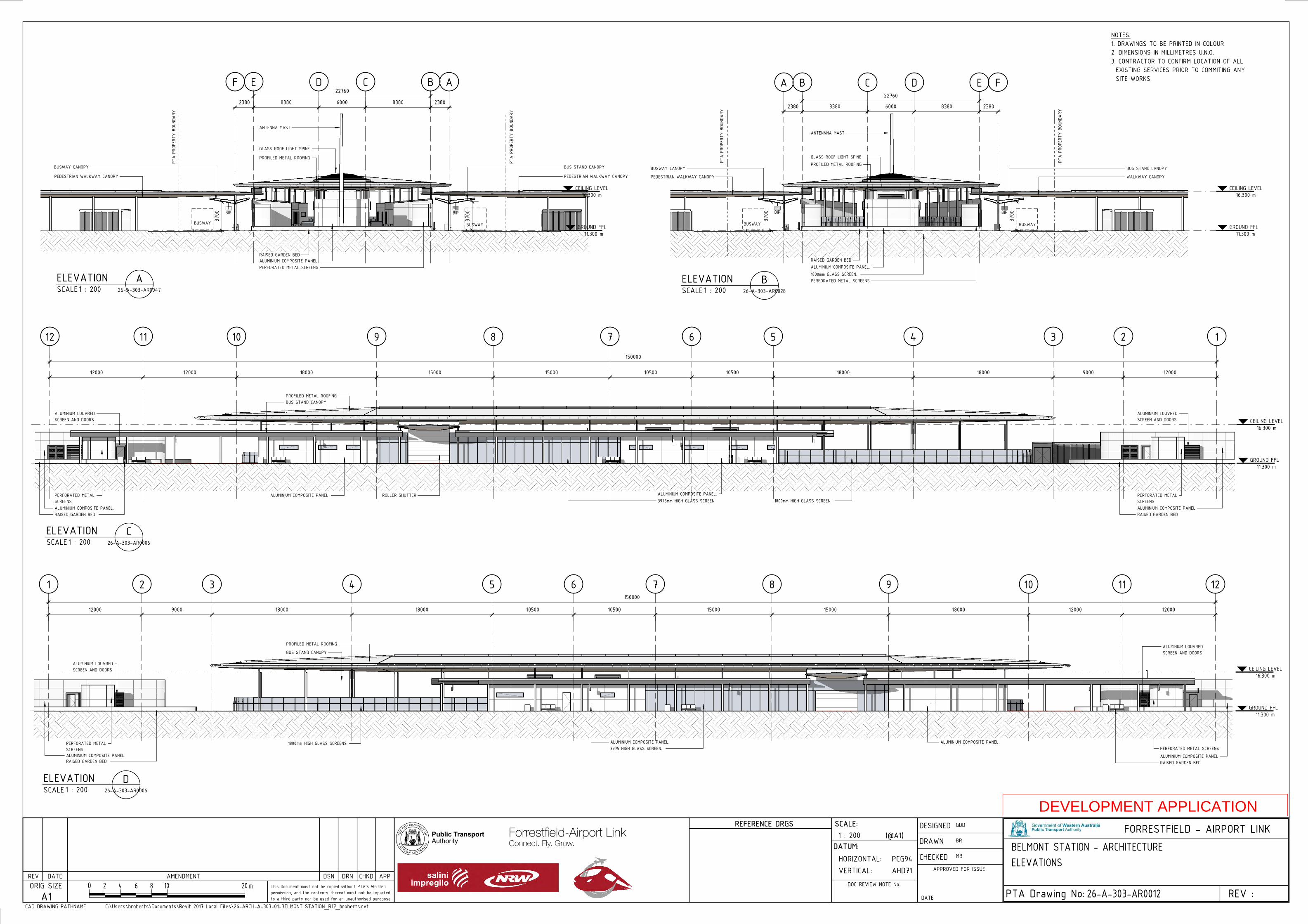
GROUND FFL11.300 m
BCE2380 8380 6000 8380 2380
PTA
PROP
ERTY
BOU
NDAR
YBUS STAND CANOPYBUSWAY CANOPY
PEDESTRIAN WALKWAY CANOPY
PROFILED METAL ROOFING
GLASS ROOF LIGHT SPINE
ALUMINIUM COMPOSITE PANEL PERFORATED METAL SCREENS
BUSWAY
D
CEILING LEVEL16.300 m
3700
3700
AF
PTA
PROP
ERTY
BOU
NDAR
Y
BIPBIP
BUSWAY
22760
PEDESTRIAN WALKWAY CANOPY
ANTENNA MAST
RAISED GARDEN BED
GROUND FFL11.300 m
B C E
2380 8380 6000 8380 2380
BUS STAND CANOPY
WALKWAY CANOPY
BUSWAY CANOPYPROFILED METAL ROOFING GLASS ROOF LIGHT SPINE
ALUMINIUM COMPOSITE PANEL. 1800mm GLASS SCREEN. PERFORATED METAL SCREENS
BUSWAY
D
CEILING LEVEL16.300 m
BUSWAY
3700
3700
A F
PTA
PROP
ERTY
BOU
NDAR
Y
PTA
PROP
ERTY
BOU
NDAR
Y
BIPBIP
22760
PEDESTRIAN WALKWAY CANOPY
ANTENNNA MAST
RAISED GARDEN BED
GROUND FFL11.300 m
123456789101112
12000 12000 18000 15000 15000 10500 10500 18000 18000 9000 12000
BUS STAND CANOPY
ALUMINIUM COMPOSITE PANEL. 1800mm HIGH GLASS SCREEN.
PROFILED METAL ROOFING
ALUMINIUM COMPOSITE PANEL. 3975mm HIGH GLASS SCREEN.
ALUMINIUM COMPOSITE PANEL.
PERFORATED METAL SCREENS
ALUMINIUM COMPOSITE PANEL
PERFORATED METAL SCREENS
RAISED GARDEN BED RAISED GARDEN BED
CEILING LEVEL16.300 m
ALUMINIUM LOUVRED SCREEN AND DOORS
ALUMINIUM LOUVRED SCREEN AND DOORS
ROLLER SHUTTER
150000
GROUND FFL11.300 m
1 2 3 4 5 6 7 8 9 10 11 12
120001200018000150001500010500105001800018000900012000
BUS STAND CANOPY
1800mm HIGH GLASS SCREENS
PROFILED METAL ROOFING
ALUMINIUM COMPOSITE PANEL. 3975 HIGH GLASS SCREEN.
ALUMINIUM COMPOSITE PANEL.
PERFORATED METAL SCREENS
ALUMINIUM COMPOSITE PANEL
PERFORATED METAL SCREENS
RAISED GARDEN BED RAISED GARDEN BED
ALUMINIUM COMPOSITE PANEL.
CEILING LEVEL16.300 m
ALUMINIUM LOUVRED SCREEN AND DOORS
ALUMINIUM LOUVRED SCREEN AND DOORS
150000
0REV :
FORRESTFIELD - AIRPORT LINK
PTA Drawing No:
(@A1)
ORIG SIZEA1
REV DATE AMENDMENT DRN CHKD APP
CAD DRAWING PATHNAME
SCALE:
VERTICAL:HORIZONTAL:
DATUM:
AHD71PCG94
DOC REVIEW NOTE No.2 4 6 8 10 m20
REFERENCE DRGS
DSNThis Document must not be copied without PTA's Written permission, and the contents thereof must not be imparted to a third party nor be used for an unauthorised puropose
APPROVED FOR ISSUE
CHECKED
DRAWN
DESIGNED
DATEC:\Users\broberts\Documents\Revit 2017 Local Files\26-ARCH-A-303-01-BELMONT STATION_R17_broberts.rvt
1 : 200
26-A-303-AR0012
GDD
BR
MBBELMONT STATION - ARCHITECTUREELEVATIONS
SCALEELEVATION
1 : 200 26-A-303-AR0047
ASCALEELEVATION
1 : 200 26-A-303-AR0028
B
SCALEELEVATION
1 : 200 26-A-303-AR0006
C
SCALEELEVATION
1 : 200 26-A-303-AR0006
D
NOTES:1. DRAWINGS TO BE PRINTED IN COLOUR2. DIMENSIONS IN MILLIMETRES U.N.O.3. CONTRACTOR TO CONFIRM LOCATION OF ALL EXISTING SERVICES PRIOR TO COMMITING ANY SITE WORKS
DEVELOPMENT APPLICATION

MEZZANINE FFL6.570 m
GROUND FFL11.300 m
PLATFORM FFL1.665 m
BASE SLAB-0.010 m
12345678910111212000 12000 18000 15000 15000 10500 10500 18000 18000 9000 12000
4905
4730
5000
PLATFORM
PROFILED METAL ROOFING
1500mm GLASS SCREEN.
STAIR
PLATFORM OFFICEALUMINIUM COMPOSITE PANEL.
1800mm GLASS SCREEN. 3975mm GLASS SCREEN.
ADVERTISING PANELS
LIFT 1
ALUMINIUM COMPOSITE PANEL.
CID
CEILING LEVEL16.300 m
ESCALATORSESCALATORS
ALUMINIUM CEILING
CABLE CONTAINMENT SMOKE BAFFLE
ALUMINIUM CEILING SMOKE BAFFLE
ADVERTISING PANEL LIFT 2
CABLE CONTAINMENT
150000
MEZZANINE FFL6.570 m
GROUND FFL11.300 m
PLATFORM FFL1.665 m
BASE SLAB-0.010 m
BCE2380 8380 6000 8380 2380
5000
4730
4905
BUSWAY CANOPY
PEDESTRIAN WALKWAY CANOPYGLASS ROOF LIGHT SPINE
PROFILED METAL ROOF SHEETING BUSWAY CANOPY
BUSWAY
'D' WALL
PLATFORM PLATFORM
BID BID
D
CEILING LEVEL16.300 m
AF
PTA
PROP
ERTY
BO
UNDA
RY
PTA
PROP
ERTY
BO
UNDA
RY
1255
TOP
OF W
ALL
7500
CABLE CONTAINMENT
SERVICES ZONE
BUSWAY
ROLLER SHUTTERROLLER SHUTTER
PIMPIM
22760
PEDESTRIAN WALKWAY CANOPY
5000
4730
4905
1675
MEZZANINE FFL6.570 m
GROUND FFL11.300 m
PLATFORM FFL1.665 m
BASE SLAB-0.010 m
1 2 3 4 5 6 7 8 9 10 11 12
CEILING LEVEL16.300 m
12000120001800015000150001050010500180001800090001200049
0547
3050
00
PLATFORM
PROFILED METAL ROOFING
1500mm GLASS SCREEN.
STAIRPLATFORM OFFICE
1800mm GLASS SCREEN. 3450mm GLASS SCREEN.
ADVERTISING PANELS
LIFT 1
ALUMINIUM COMPOSITE PANEL.
CID
ESCALATORSFUTURE ESCALATORS
ALUMINIUM CEILING
ALUMINIUM CEILING SMOKE BAFFLE
ALUMINIUM CEILING SMOKE BAFFLE
CABLE CONTAINMENT
LIFT 2
ROLLER SHUTTER
CABLE CONTAINMENT
ADVERTISING PANEL
ACOUSTIC PANELLINGHIGH PRESSURE LAMINATE LINING
PLATFORM
150000
0REV :
FORRESTFIELD - AIRPORT LINK
PTA Drawing No:
(@A1)
ORIG SIZEA1
REV DATE AMENDMENT DRN CHKD APP
CAD DRAWING PATHNAME
SCALE:
VERTICAL:HORIZONTAL:
DATUM:
AHD71PCG94
DOC REVIEW NOTE No.2 4 6 8 10 m20
REFERENCE DRGS
DSNThis Document must not be copied without PTA's Written permission, and the contents thereof must not be imparted to a third party nor be used for an unauthorised puropose
APPROVED FOR ISSUE
CHECKED
DRAWN
DESIGNED
DATEC:\Users\broberts\Documents\Revit 2017 Local Files\26-ARCH-A-303-01-BELMONT STATION_R17_broberts.rvt
1 : 200
26-A-303-AR0013
GDD
BR
MBBELMONT STATION - ARCHITECTUREBUILDING SECTIONS
SCALESECTION
1 : 200 26-A-303-AR0005
B
SCALESECTION
1 : 200 26-A-303-AR0005
C
SCALESECTION
1 : 200 26-A-303-AR0005
A
NOTES:1. DRAWINGS TO BE PRINTED IN COLOUR2. DIMENSIONS IN MILLIMETRES U.N.O.3. CONTRACTOR TO CONFIRM LOCATION OF ALL EXISTING SERVICES PRIOR TO COMMITING ANY SITE WORKS
DEVELOPMENT APPLICATION
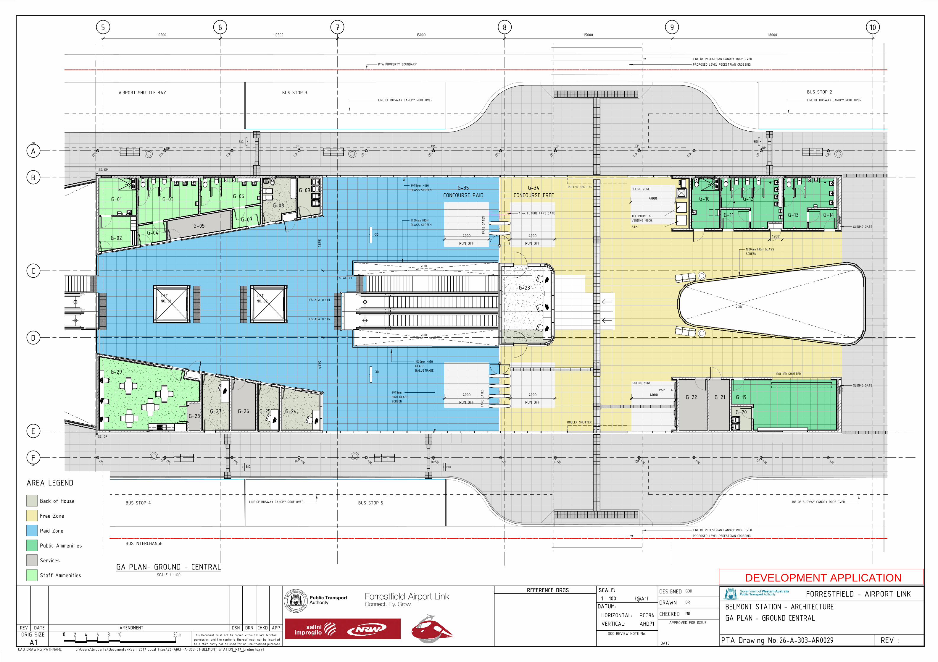
5 6 7 8 9 10
B
C
E
D
A
F
1200
4890
4898
AREA LEGEND
Back of House
Free Zone
Paid Zone
Public Ammenities
Services
Staff Ammenities
ATM
ESCALATOR 01
ESCALATOR 02
VOID
FARE
GAT
ESFA
RE G
ATES
ROLLER SHUTTER
PSP
QUEING ZONE
VOID
QUEING ZONE
LINE OF BUSWAY CANOPY ROOF OVER
BUS INTERCHANGE
CID
CID
TELEPHONE & VENDING MECH.
LIFT NO. 02
LIFT NO. 01
1400mm HIGH GLASS SCREEN
1500mm HIGH GLASS BALUSTRADE
3975mm HIGH GLASS SCREEN
3975mm HIGH GLASS SCREEN
RUN OFF
4000
1800mm HIGH GLASS SCREEN
1 No. FUTURE FARE GATE
RUN OFF
4000
RUN OFF
4000
RUN OFF
4000
ROLLER SHUTTER
PTA PROPERTY BOUNDARY
LINE OF BUSWAY CANOPY ROOF OVER
4000
STAIR 01
ROLLER SHUTTER
4000
LINE OF BUSWAY CANOPY ROOF OVER
AIRPORT SHUTTLE BAY BUS STOP 3 BUS STOP 2
BUS STOP 4 BUS STOP 5
DP
SS. DP
DPDP DP
DP
SS. DP
DP DP DP DP DPDP
G-01
G-02
G-03
G-04G-05
G-06
G-07
G-08
G-09
G-29
G-28G-27 G-26 G-25 G-24
G-10 G-12
G-11 G-13 G-14
G-22 G-21 G-19
G-20
G-35 G-34CONCOURSE PAID CONCOURSE FREE
10500 10500 15000 15000 18000
LINE OF BUSWAY CANOPY ROOF OVER
LINE OF PEDESTRIAN CANOPY ROOF OVER
PROPOSED LEVEL PEDESTRIAN CROSSING
G-23
BID.
COL.
COL.
COL.
COL.
COL.
COL.
COL.
COL.
COL.
COL.
COL.
COL.
DP DP DP
BID.
COL.
COL.
COL.
COL.
COL.
COL.
COL.
COL.
COL.
COL.
COL.
COL.
BID.BID.
VOID
LINE OF PEDESTRIAN CANOPY ROOF OVER
PROPOSED LEVEL PEDESTRIAN CROSSING
SLIDING GATE
SLIDING GATE
0REV :
FORRESTFIELD - AIRPORT LINK
PTA Drawing No:
(@A1)
ORIG SIZEA1
REV DATE AMENDMENT DRN CHKD APP
CAD DRAWING PATHNAME
SCALE:
VERTICAL:HORIZONTAL:
DATUM:
AHD71PCG94
DOC REVIEW NOTE No.2 4 6 8 10 m20
REFERENCE DRGS
DSNThis Document must not be copied without PTA's Written permission, and the contents thereof must not be imparted to a third party nor be used for an unauthorised puropose
APPROVED FOR ISSUE
CHECKED
DRAWN
DESIGNED
DATEC:\Users\broberts\Documents\Revit 2017 Local Files\26-ARCH-A-303-01-BELMONT STATION_R17_broberts.rvt
1 : 100
26-A-303-AR0029
GDD
BR
MBBELMONT STATION - ARCHITECTUREGA PLAN - GROUND CENTRAL
SCALE 1 : 100GA PLAN- GROUND - CENTRAL
DEVELOPMENT APPLICATION
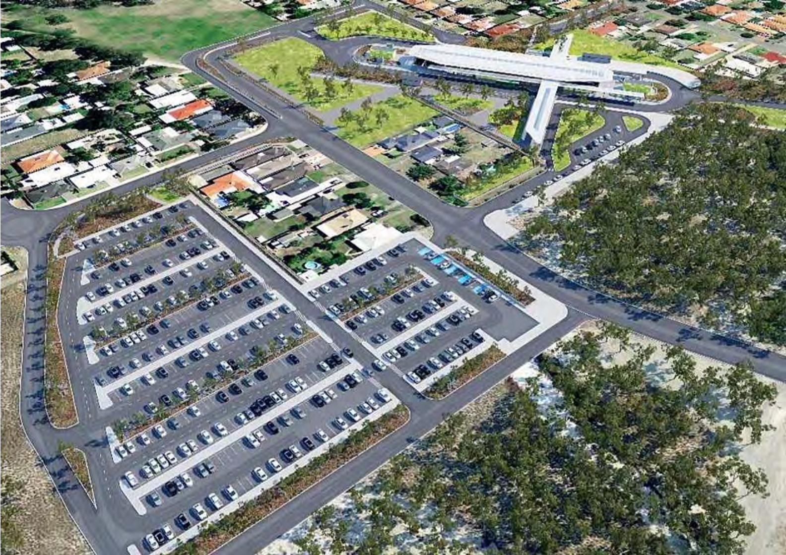

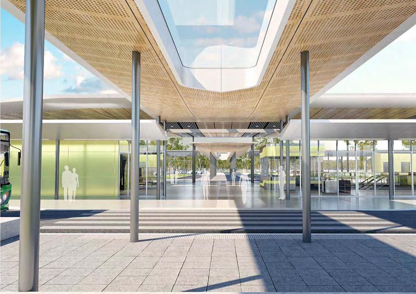

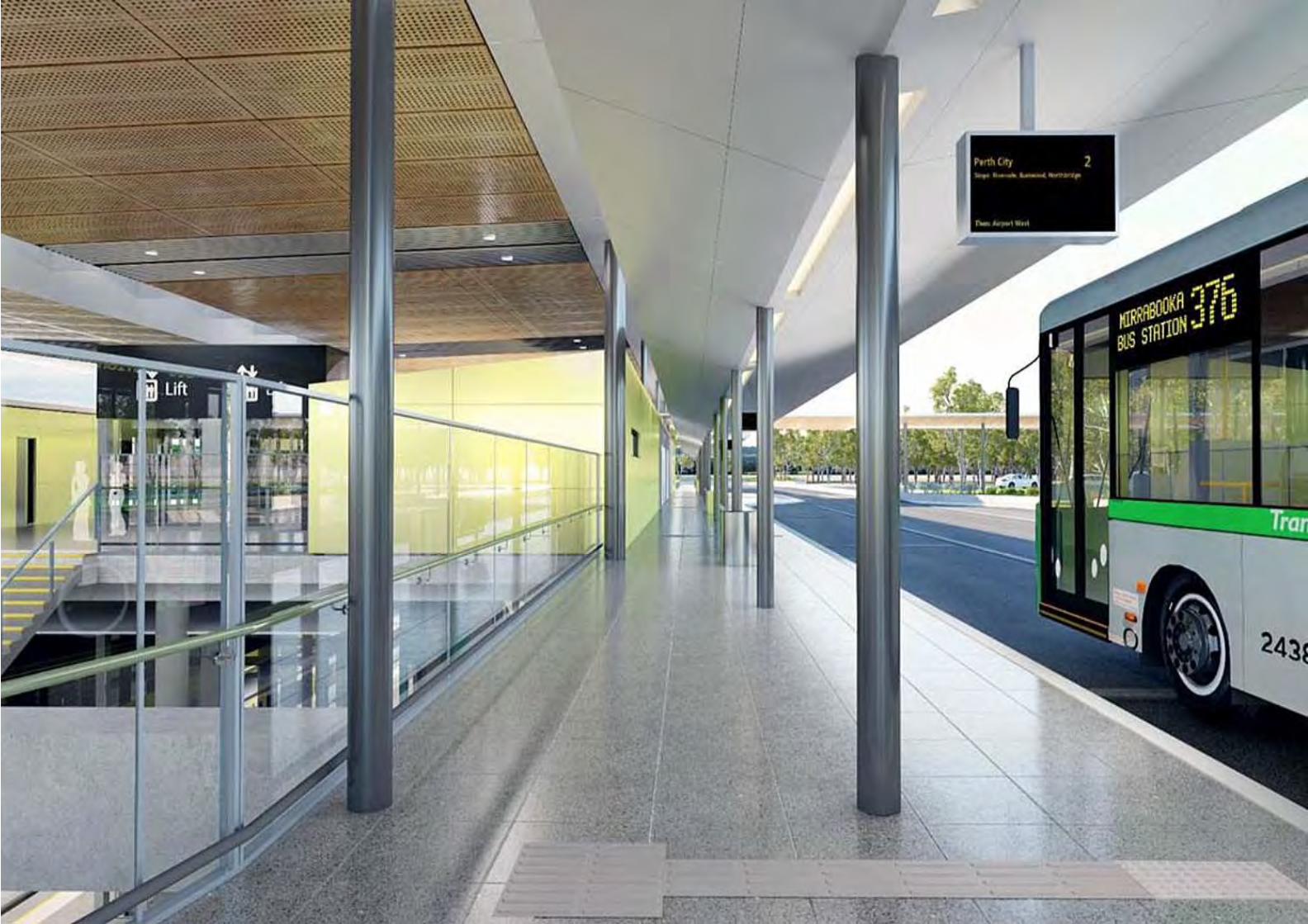
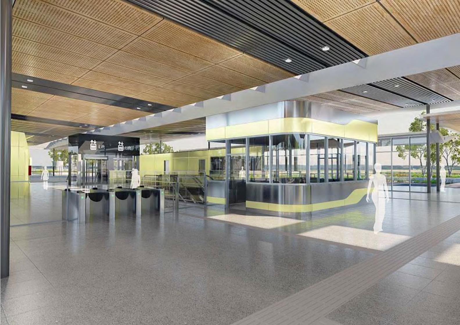

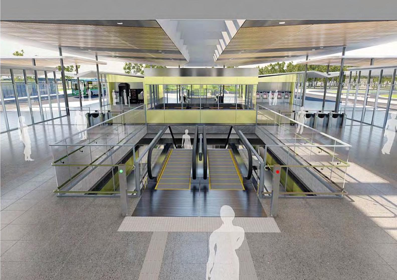
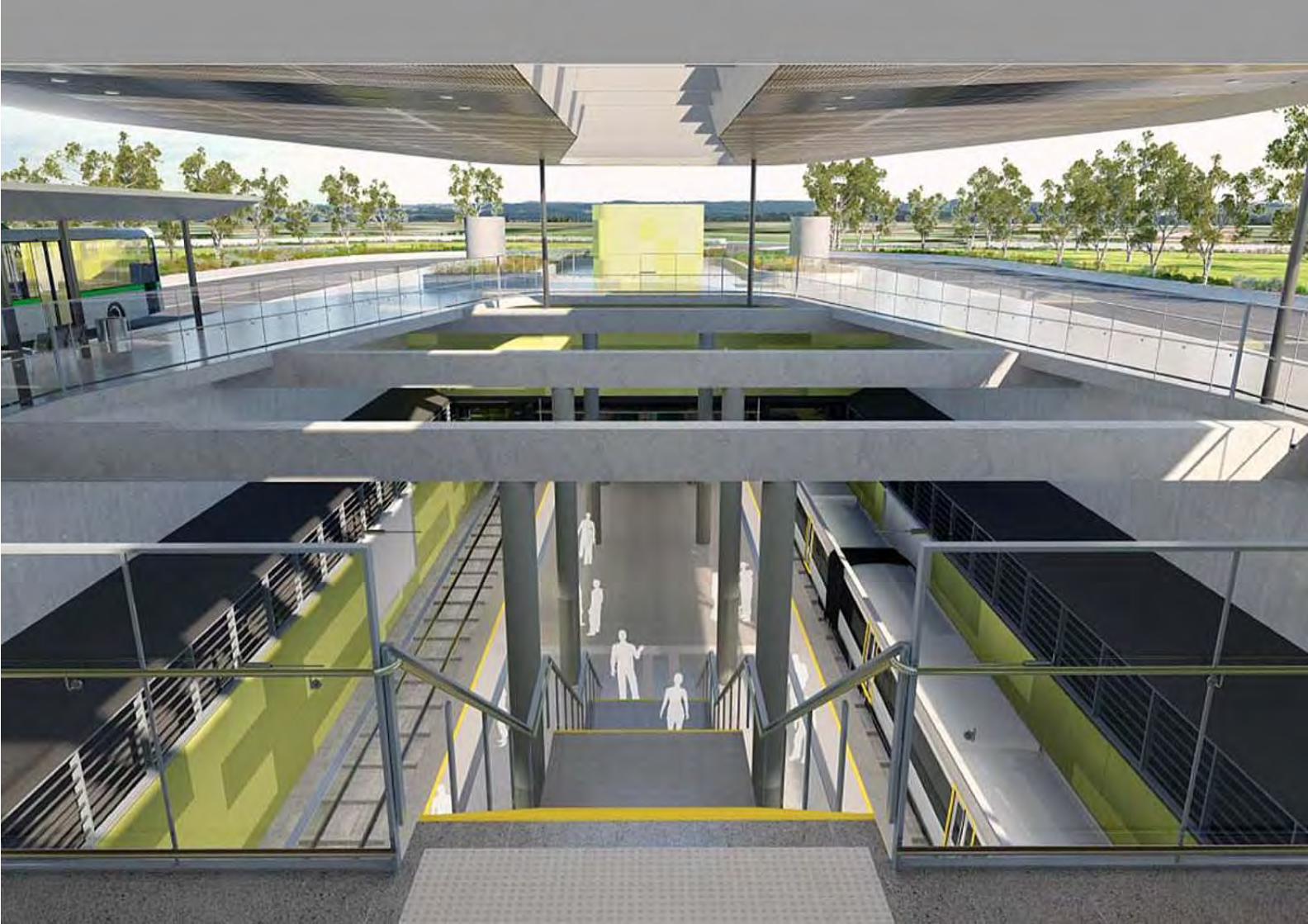

Belmont Station Development Application Report 57
Appendix 2: Transport Assessment
17 September 2015
CONFIDENTIAL
Forrestfield Airport Link Project
Transport Assessment – Airport West
Station Prepared by PTA
FAL Document Number: FAL-PTAWA-TM-RPT-00010

Table of Contents
1. Summary ............................................................................................................................... 6
2. Introduction .......................................................................................................................... 7
2.1 Name of applicant ................................................................................................................. 7
2.2 Development location and context ...................................................................................... 7
2.3 Airport West Station ............................................................................................................. 8
2.4 Key issues .............................................................................................................................. 9
2.5 Background information ..................................................................................................... 10
3. Development proposal ....................................................................................................... 10
3.1 Regional context ................................................................................................................. 10
3.2 Proposed land uses ............................................................................................................. 11
3.3 Staging of the development ................................................................................................ 11
3.4 Access arrangements .......................................................................................................... 11
3.4.1 Walking and cycling ....................................................................................................... 11
3.4.2 Public transport access ................................................................................................. 12
3.4.3 Private vehicle access .................................................................................................... 13
3.5 Parking provision ................................................................................................................. 14
3.6 End of trip facilities ............................................................................................................. 15
3.7 Any specific issues ............................................................................................................... 15
4. Existing situation ................................................................................................................. 16
4.1 Existing site uses ................................................................................................................. 16
4.2 Existing access arrangements ............................................................................................. 16
4.3 Surrounding land uses ........................................................................................................ 16
4.4 Surrounding road network .................................................................................................. 16
4.5 Traffic management on frontage roads .............................................................................. 17
4.6 Traffic flows on surrounding roads (AM and PM peak hours) ............................................ 17
4.7 Traffic flows at major intersections (AM and PM peak hours) ........................................... 18
4 Forrestfield Airport Link: TIA – Airport West Station | 17/09/15
4.8 Existing pedestrian and cycle networks .............................................................................. 18
4.9 Existing public transport services surrounding the development ...................................... 19
4.9.1 Local Services ................................................................................................................ 19
4.9.2 Services to the Development Site ................................................................................. 20
4.10 Crash data ........................................................................................................................... 21
5. Changes to surrounding transport networks ...................................................................... 21
5.1 Road network ...................................................................................................................... 21
5.1.1 PTA’s planned changes to the road network ................................................................ 22
5.1.2 The City of Belmont’s planned changes to the road network ...................................... 23
5.2 Pedestrian and cycle networks and crossing facilities ........................................................ 23
5.3 Public transport services ..................................................................................................... 24
6. Integration with surrounding area ...................................................................................... 24
6.1 Surrounding major attractors/generators .......................................................................... 24
6.2 Proposed changes to land uses within 1200m ................................................................... 24
6.3 Travel desire lines from development to these attractors/generators .............................. 24
6.4 Adequacy of existing transport networks ........................................................................... 25
6.4.1 Pedestrian and cycle networks ..................................................................................... 25
6.4.2 Road network ................................................................................................................ 26
7. Analysis of transport networks ........................................................................................... 26
7.1 Parking supply and demand ................................................................................................ 26
7.2 Committed developments and transport proposals .......................................................... 26
7.2.1 Road Network ............................................................................................................... 27
7.2.2 Perth Airport ................................................................................................................. 27
7.3 Assessment years ................................................................................................................ 28
7.4 Time periods ....................................................................................................................... 28
7.5 Development and distribution of generated traffic ........................................................... 29
7.5.1 Trip generation .............................................................................................................. 29
7.5.2 Trip distribution ............................................................................................................ 29
5 Forrestfield Airport Link: TIA – Airport West Station | 17/09/15
7.6 Base and “with development” traffic flows ........................................................................ 32
7.7 Impact on intersections ...................................................................................................... 33
7.7.1 Central Avenue / Second Street Intersection ............................................................... 33
7.7.2 Central Avenue / Park n Ride Intersection .................................................................... 34
7.7.3 Boulder Avenue / Second Street Roundabout .............................................................. 35
7.8 Impact on neighbouring areas ............................................................................................ 35
7.9 Traffic noise and vibration .................................................................................................. 35
7.10 Road safety.......................................................................................................................... 36
7.11 Public transport access ....................................................................................................... 36
8. Analysis of pedestrian and cycle networks ......................................................................... 37
8.1 Pedestrian access and amenity ........................................................................................... 37
8.1.1 Existing pedestrian network ......................................................................................... 38
8.1.2 Changes to pedestrian networks and crossing facilities ............................................... 38
8.1.3 Integration of the pedestrian networks ........................................................................ 38
8.1.4 Development pedestrian access arrangements ........................................................... 39
8.2 Cycle access and amenity .................................................................................................... 39
8.2.1 Existing cycle network ................................................................................................... 39
8.2.2 Changes to cycle networks and crossing facilities ........................................................ 39
8.2.3 Integration of the cycle networks ................................................................................. 40
8.2.4 Development cycle access arrangements ..................................................................... 41
9. Conclusions ......................................................................................................................... 41
Appendices
Appendix 1 – Figures ............................................................................................................................. 43
Appendix 2 – Sidra Results .................................................................................................................... 45
6 Forrestfield Airport Link: TIA – Airport West Station | 17/09/15
1. Summary
This Traffic Impact Assessment is written to support the Public Transport Authority’s (PTA)
Development Application for the Airport West Station, Redcliffe. The Station will have a below
ground rail station, a bus facility, kiss and ride provision and a 500 bay car park.
The Station will be developed in what is currently the road reserve for Brearley Avenue, Redcliffe,
and will also utilise some of the surrounding reserves used for public open space. The existing land
use does not generate any traffic and the closure of Brearley Avenue will remove some 36,000
vehicles per day (VPD) from Redcliffe.
Pedestrians will be attracted to the Station from the surrounding residential land. There is low
density residential land with a number of cul de sacs and it has been identified that there are gaps in
the footpath network. The Station development will provide new footpath connections and crossing
facilities so that it is well integrated into the existing land and the future higher density land
development.
Cyclists will be attracted to the Station with the provision of secure cycle facilities that can be
accessed using a SmartRider. There is a good cycle network surrounding the Station, and within
1200m.
The Station will provide much needed public transport links for the area, including the proposed
developments in the western precinct of Perth Airport. The Station will provide a terminus for bus
services to the surrounding areas and will allow Transperth to increase bus services, this includes
high frequency services on Great Eastern Highway. The Fauntleroy Avenue / Great Eastern Highway
intersection is being upgraded to reduce delay for buses accesses the Station via Dunreath Drive.
Buses will also use the existing route on Second Street. All buses will use a newly upgraded section
of Central Avenue, north of Second Street. A connecting road from this upgraded section of Central
Avenue to Bulong Avenue will be constructed to give buses access to the Station.
The PTA will construct an extension to Central Avenue from Second Street to Dunreath Drive, prior
to the closure of Brearley Avenue. The existing bus route 37, which is one of Transperth’s most
popular routes, accesses the Airport via Brearley Avenue and so the new connection will be used to
access the Airport.
There will be a dedicated kiss and ride facility at the Station as well as on road, short term, parking
bays. It is expected that three quarters of the kiss and ride traffic will be attracted from Belmont and
7 Forrestfield Airport Link: TIA – Airport West Station | 17/09/15
the southern section of Redcliffe. This traffic will use Stanton Road to access the Station. Stanton
Road and Second Street have sufficient capacity to cater for the additional traffic.
Cars will access the 500 bay park and ride car park from Second Street and the extension of Central
Avenue. The traffic will be attracted in even numbers from Second Street and Central Avenue. To
facilitate access to the car park the PTA will construct an extension to Boulder Avenue from a new
roundabout to be constructed at the Boulder Avenue / Second Street intersection. A second access
to the car park will be from the extension to Central Avenue.
Based on PTA’s experience at similar stations the morning peak time for the car park will be earlier
than for the surrounding road network. The morning peak is relatively short with the evening peak
happening over a two hour period. The traffic modelling shows that the surrounding intersections
have capacity to cater for the increase in traffic.
The Station will:
• provide safe and efficient access for all modes;
• be well integrated with the surrounding land uses;
• not adversely impact on the surrounding land uses; and
• not adversely impact on the surrounding transport networks and the users of those
networks.
2. Introduction
2.1 Name of applicant
This report accompanies the Public Transport Authority’s (PTA) development application for the
Airport West Station, Redcliffe.
2.2 Development location and context
The route for the Forrestfield-Airport Link (FAL) was announced by the WA Government in August
2014. The route will open up a new rail corridor to the eastern suburbs and foothills, allowing a 20-
minute rail journey to the Perth central business district from the airport. The rail connection will
improve public transport access for passengers from Bayswater, Belmont, Redcliffe and Forrestfield
as well as areas such as Wattle Grove, Maida Vale and High Wycombe.
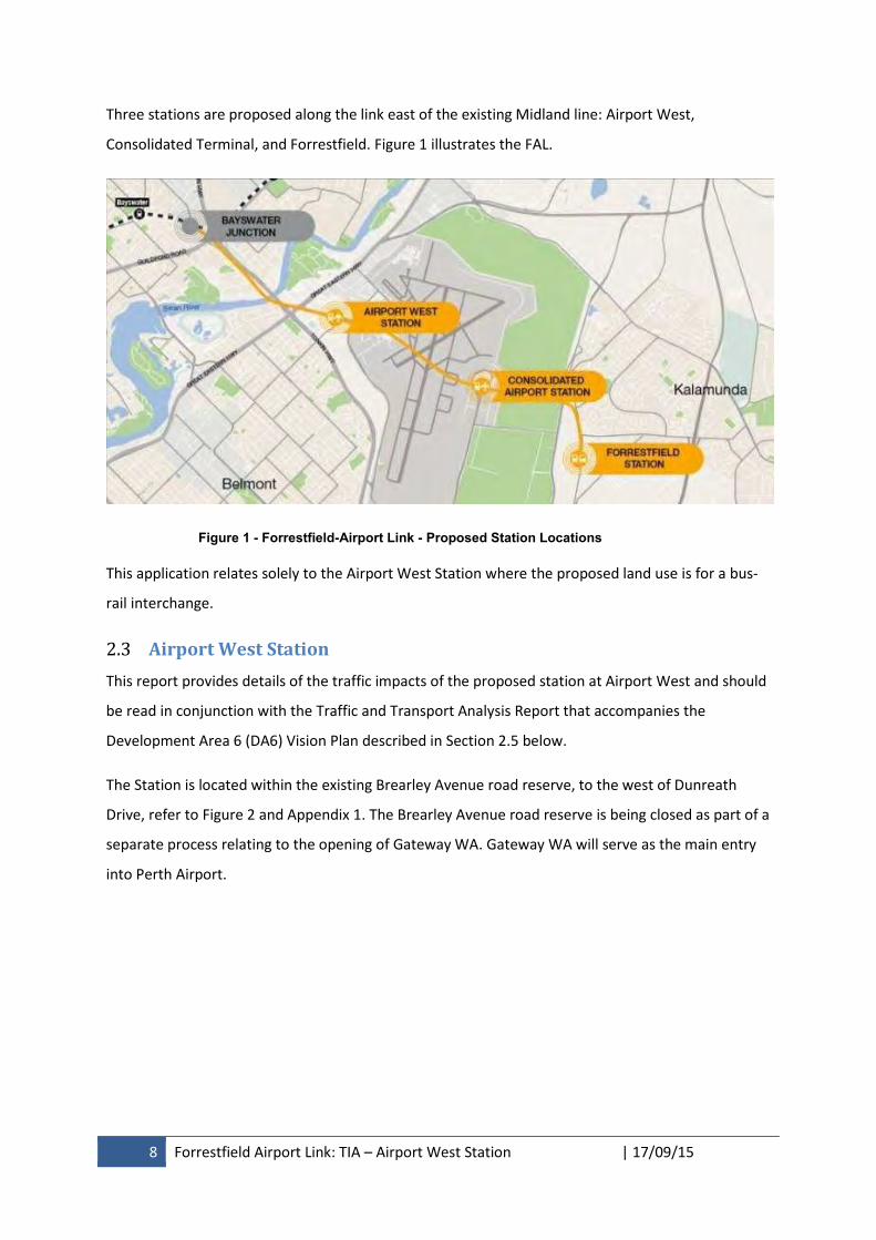
8 Forrestfield Airport Link: TIA – Airport West Station | 17/09/15
Three stations are proposed along the link east of the existing Midland line: Airport West,
Consolidated Terminal, and Forrestfield. Figure 1 illustrates the FAL.
Figure 1 - Forrestfield-Airport Link - Proposed Station Locations
This application relates solely to the Airport West Station where the proposed land use is for a bus-
rail interchange.
2.3 Airport West Station
This report provides details of the traffic impacts of the proposed station at Airport West and should
be read in conjunction with the Traffic and Transport Analysis Report that accompanies the
Development Area 6 (DA6) Vision Plan described in Section 2.5 below.
The Station is located within the existing Brearley Avenue road reserve, to the west of Dunreath
Drive, refer to Figure 2 and Appendix 1. The Brearley Avenue road reserve is being closed as part of a
separate process relating to the opening of Gateway WA. Gateway WA will serve as the main entry
into Perth Airport.
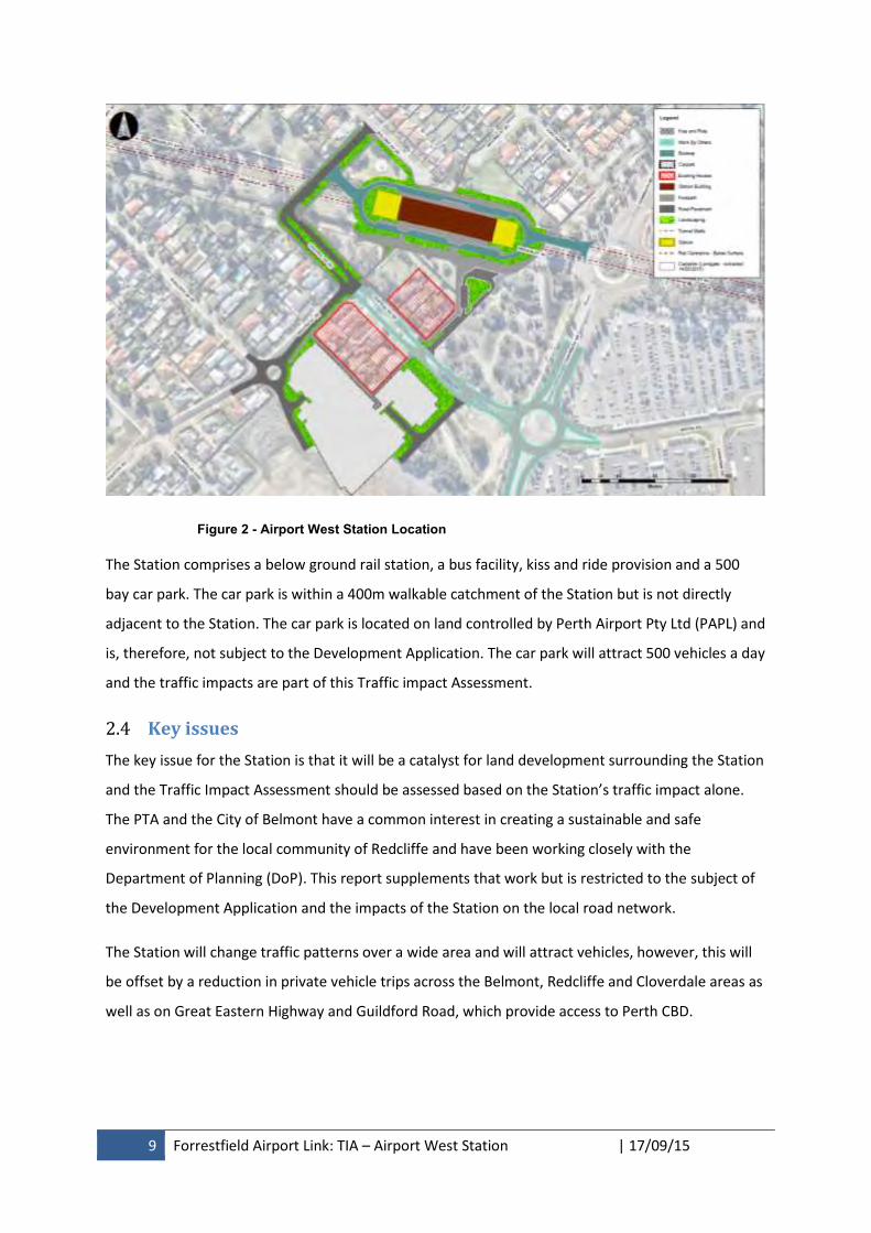
9 Forrestfield Airport Link: TIA – Airport West Station | 17/09/15
Figure 2 - Airport West Station Location
The Station comprises a below ground rail station, a bus facility, kiss and ride provision and a 500
bay car park. The car park is within a 400m walkable catchment of the Station but is not directly
adjacent to the Station. The car park is located on land controlled by Perth Airport Pty Ltd (PAPL) and
is, therefore, not subject to the Development Application. The car park will attract 500 vehicles a day
and the traffic impacts are part of this Traffic impact Assessment.
2.4 Key issues
The key issue for the Station is that it will be a catalyst for land development surrounding the Station
and the Traffic Impact Assessment should be assessed based on the Station’s traffic impact alone.
The PTA and the City of Belmont have a common interest in creating a sustainable and safe
environment for the local community of Redcliffe and have been working closely with the
Department of Planning (DoP). This report supplements that work but is restricted to the subject of
the Development Application and the impacts of the Station on the local road network.
The Station will change traffic patterns over a wide area and will attract vehicles, however, this will
be offset by a reduction in private vehicle trips across the Belmont, Redcliffe and Cloverdale areas as
well as on Great Eastern Highway and Guildford Road, which provide access to Perth CBD.
10 Forrestfield Airport Link: TIA – Airport West Station | 17/09/15
2.5 Background information
The station is within DA6 which is bounded by Great Eastern Highway and Tonkin Highway in
Redcliffe, and extends into the existing Domestic Airport terminal. DA6 is approximately 174
hectares in size, of which 105 hectares is controlled by PAPL, with the remainder under the planning
control of the City.
A vision plan has been prepared for the DA6 area proposing a mixed use scenario that delivers a
Transit Oriented Development (TOD) outcome.
The objectives for the Airport West station, with amenities that complement the DA6 Vision Plan for
the area, can be summarised as follows:
A large space which focuses on community life, gatherings, markets and social area with 24
hour safe access;
Setting for local retail activity;
Activation of streets and pedestrian paths around and leading to the plaza;
Public and private alfresco space;
Family friendly; and
Engaging, vibrant public destination for workers and residents.
3. Development proposal
3.1 Regional context
The FAL is important for the Eastern Suburbs as it provides an efficient public transport link to the
Perth CBD and beyond. It will also become an increasingly important public transport connection to
Perth Airport, which serves as the principal passenger airport for Western Australia. Perth Airport
comprises a total of 2,105ha and attracts approximately 17,800 employees to the site daily. The
Perth Airport Draft Master Plan 2014 states that by 2019 the number of employees is expected to
grow to 23,860.
As the development of a business park progresses in the Airport West Precinct of the Airport the
Station will increasingly become a destination station in the mornings, delivering workers to the
business park.
The proposed development is wholly within the DA6.
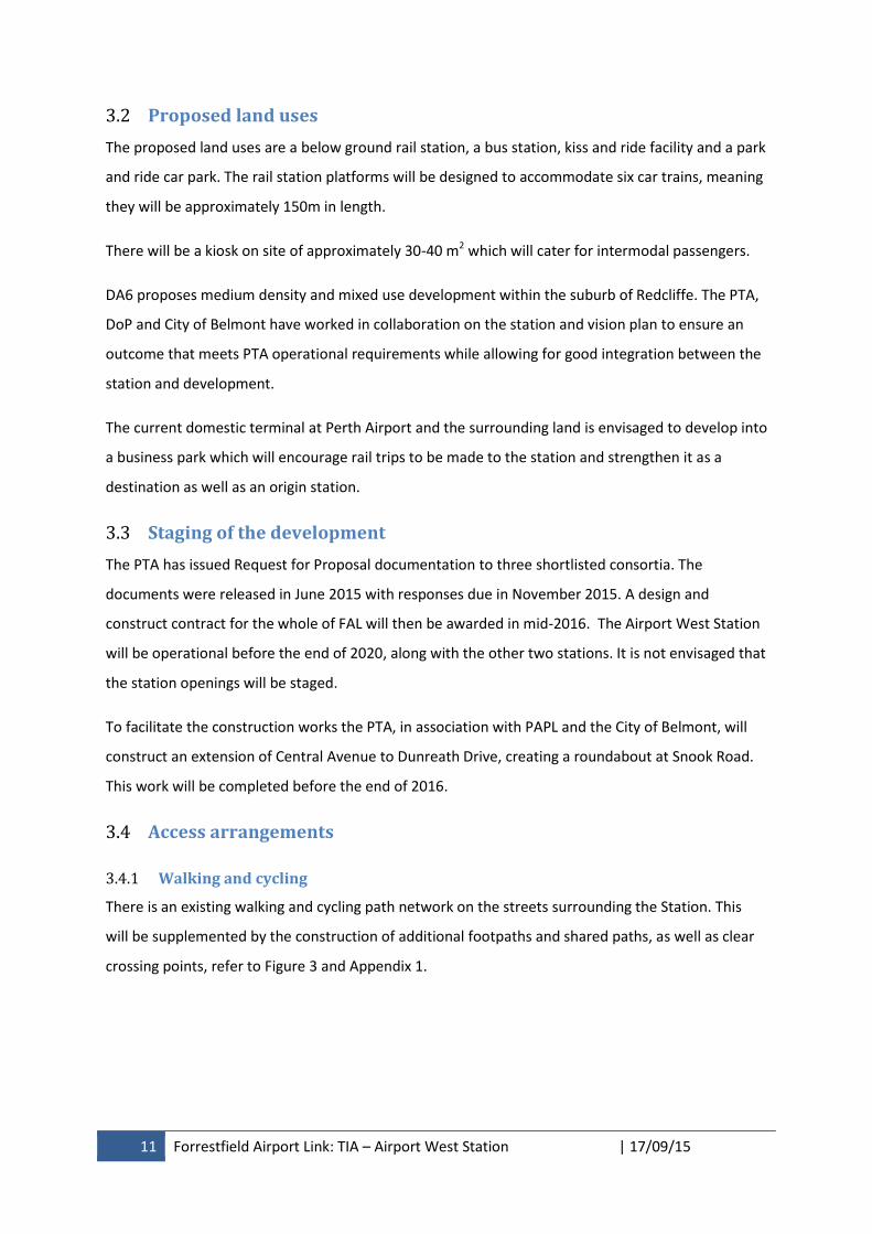
11 Forrestfield Airport Link: TIA – Airport West Station | 17/09/15
3.2 Proposed land uses
The proposed land uses are a below ground rail station, a bus station, kiss and ride facility and a park
and ride car park. The rail station platforms will be designed to accommodate six car trains, meaning
they will be approximately 150m in length.
There will be a kiosk on site of approximately 30-40 m2 which will cater for intermodal passengers.
DA6 proposes medium density and mixed use development within the suburb of Redcliffe. The PTA,
DoP and City of Belmont have worked in collaboration on the station and vision plan to ensure an
outcome that meets PTA operational requirements while allowing for good integration between the
station and development.
The current domestic terminal at Perth Airport and the surrounding land is envisaged to develop into
a business park which will encourage rail trips to be made to the station and strengthen it as a
destination as well as an origin station.
3.3 Staging of the development
The PTA has issued Request for Proposal documentation to three shortlisted consortia. The
documents were released in June 2015 with responses due in November 2015. A design and
construct contract for the whole of FAL will then be awarded in mid-2016. The Airport West Station
will be operational before the end of 2020, along with the other two stations. It is not envisaged that
the station openings will be staged.
To facilitate the construction works the PTA, in association with PAPL and the City of Belmont, will
construct an extension of Central Avenue to Dunreath Drive, creating a roundabout at Snook Road.
This work will be completed before the end of 2016.
3.4 Access arrangements
3.4.1 Walking and cycling
There is an existing walking and cycling path network on the streets surrounding the Station. This
will be supplemented by the construction of additional footpaths and shared paths, as well as clear
crossing points, refer to Figure 3 and Appendix 1.
12 Forrestfield Airport Link: TIA – Airport West Station | 17/09/15
Figure 3 - Development Access for Walking and Cycling
There are two pedestrian access points to the station, one on the northern side and one on the
southern side. The unpaid zone in the centre of the Station will allow pedestrians to walk through
the Station, from north to south, without passing through a fare gate. Passengers for the train will be
able to access the platforms from fare gates to one side of this walkway.
3.4.2 Public transport access
Trains will access the Station via tunnel. The railway line runs underground from High Wycombe to
Bayswater and will not impact on the road network, refer Figure 4 and Appendix 1.
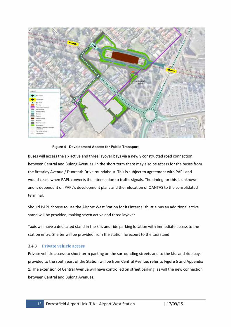
13 Forrestfield Airport Link: TIA – Airport West Station | 17/09/15
Figure 4 - Development Access for Public Transport
Buses will access the six active and three layover bays via a newly constructed road connection
between Central and Bulong Avenues. In the short term there may also be access for the buses from
the Brearley Avenue / Dunreath Drive roundabout. This is subject to agreement with PAPL and
would cease when PAPL converts the intersection to traffic signals. The timing for this is unknown
and is dependent on PAPL’s development plans and the relocation of QANTAS to the consolidated
terminal.
Should PAPL choose to use the Airport West Station for its internal shuttle bus an additional active
stand will be provided, making seven active and three layover.
Taxis will have a dedicated stand in the kiss and ride parking location with immediate access to the
station entry. Shelter will be provided from the station forecourt to the taxi stand.
3.4.3 Private vehicle access
Private vehicle access to short-term parking on the surrounding streets and to the kiss and ride bays
provided to the south east of the Station will be from Central Avenue, refer to Figure 5 and Appendix
1. The extension of Central Avenue will have controlled on street parking, as will the new connection
between Central and Bulong Avenues.
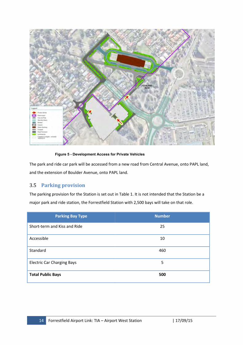
14 Forrestfield Airport Link: TIA – Airport West Station | 17/09/15
Figure 5 - Development Access for Private Vehicles
The park and ride car park will be accessed from a new road from Central Avenue, onto PAPL land,
and the extension of Boulder Avenue, onto PAPL land.
3.5 Parking provision
The parking provision for the Station is set out in Table 1. It is not intended that the Station be a
major park and ride station, the Forrestfield Station with 2,500 bays will take on that role.
Parking Bay Type Number
Short-term and Kiss and Ride 25
Accessible 10
Standard 460
Electric Car Charging Bays 5
Total Public Bays 500
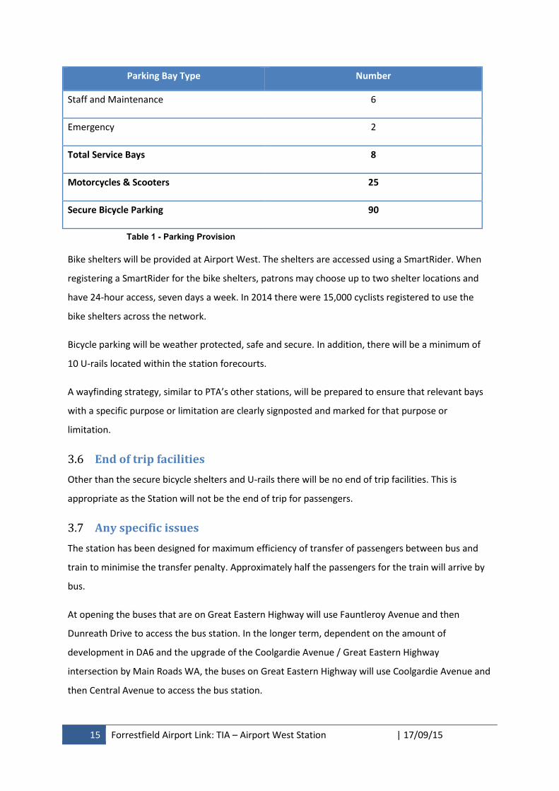
15 Forrestfield Airport Link: TIA – Airport West Station | 17/09/15
Parking Bay Type Number
Staff and Maintenance 6
Emergency 2
Total Service Bays 8
Motorcycles & Scooters 25
Secure Bicycle Parking 90
Table 1 - Parking Provision
Bike shelters will be provided at Airport West. The shelters are accessed using a SmartRider. When
registering a SmartRider for the bike shelters, patrons may choose up to two shelter locations and
have 24-hour access, seven days a week. In 2014 there were 15,000 cyclists registered to use the
bike shelters across the network.
Bicycle parking will be weather protected, safe and secure. In addition, there will be a minimum of
10 U-rails located within the station forecourts.
A wayfinding strategy, similar to PTA’s other stations, will be prepared to ensure that relevant bays
with a specific purpose or limitation are clearly signposted and marked for that purpose or
limitation.
3.6 End of trip facilities
Other than the secure bicycle shelters and U-rails there will be no end of trip facilities. This is
appropriate as the Station will not be the end of trip for passengers.
3.7 Any specific issues
The station has been designed for maximum efficiency of transfer of passengers between bus and
train to minimise the transfer penalty. Approximately half the passengers for the train will arrive by
bus.
At opening the buses that are on Great Eastern Highway will use Fauntleroy Avenue and then
Dunreath Drive to access the bus station. In the longer term, dependent on the amount of
development in DA6 and the upgrade of the Coolgardie Avenue / Great Eastern Highway
intersection by Main Roads WA, the buses on Great Eastern Highway will use Coolgardie Avenue and
then Central Avenue to access the bus station.
16 Forrestfield Airport Link: TIA – Airport West Station | 17/09/15
4. Existing situation
4.1 Existing site uses
The existing site for the Station is the Brearley Avenue road reserve. Brearley Avenue currently
carries 36,000 vehicles per day (VPD) through Redcliffe, to the Domestic Terminal of the Airport.
The existing site for the park and ride car park is vacant PAPL land.
4.2 Existing access arrangements
Vehicles access the existing site from Second Street, or from Brearley Avenue.
There is no current vehicle access to the car park site.
The existing site does not generate any traffic.
4.3 Surrounding land uses
The surrounding land use within Redcliffe is residential, zoned R20, and public open space. There is
also the Water Corporation’s Southern Main Drain in its own reserve contiguous with the road
reserve. The open drain is a Water Corporation asset and carries much of the water from the Perth
Hills and the Airport.
The land immediately to the east of the site is within the Airport and is currently vacant land. Further
east, on the other side of Dunreath Drive is the Domestic Airport and airport parking.
4.4 Surrounding road network
Brearley Avenue is a State Road, under the care and control of Main Roads WA. Dunreath Drive is a
major road within the Airport and gives access along the western side of the airport. As Dunreath
Drive is on Federal land it does not come under the State road hierarchy classifications.
Second Street is a Local Distributor as it connects with the wider road network in Redcliffe, south
west of Tonkin Highway. The remaining roads are currently Access Roads.
The surrounding Access Road network is made up of a number of cul de sacs so that the roads only
give access to the residential properties, refer to Figure 6 and Appendix 1. Boulder Avenue connects
First and Second Streets and is in the vicinity of the proposed car park.
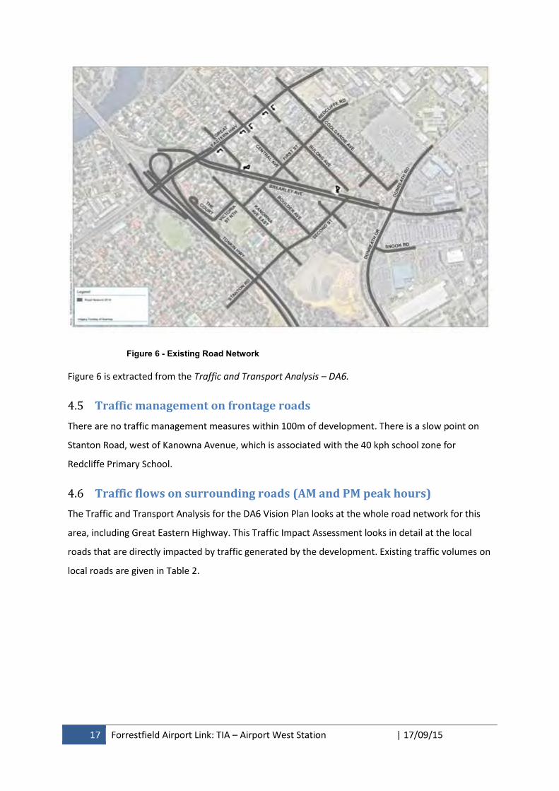
17 Forrestfield Airport Link: TIA – Airport West Station | 17/09/15
Figure 6 - Existing Road Network
Figure 6 is extracted from the Traffic and Transport Analysis – DA6.
4.5 Traffic management on frontage roads
There are no traffic management measures within 100m of development. There is a slow point on
Stanton Road, west of Kanowna Avenue, which is associated with the 40 kph school zone for
Redcliffe Primary School.
4.6 Traffic flows on surrounding roads (AM and PM peak hours)
The Traffic and Transport Analysis for the DA6 Vision Plan looks at the whole road network for this
area, including Great Eastern Highway. This Traffic Impact Assessment looks in detail at the local
roads that are directly impacted by traffic generated by the development. Existing traffic volumes on
local roads are given in Table 2.
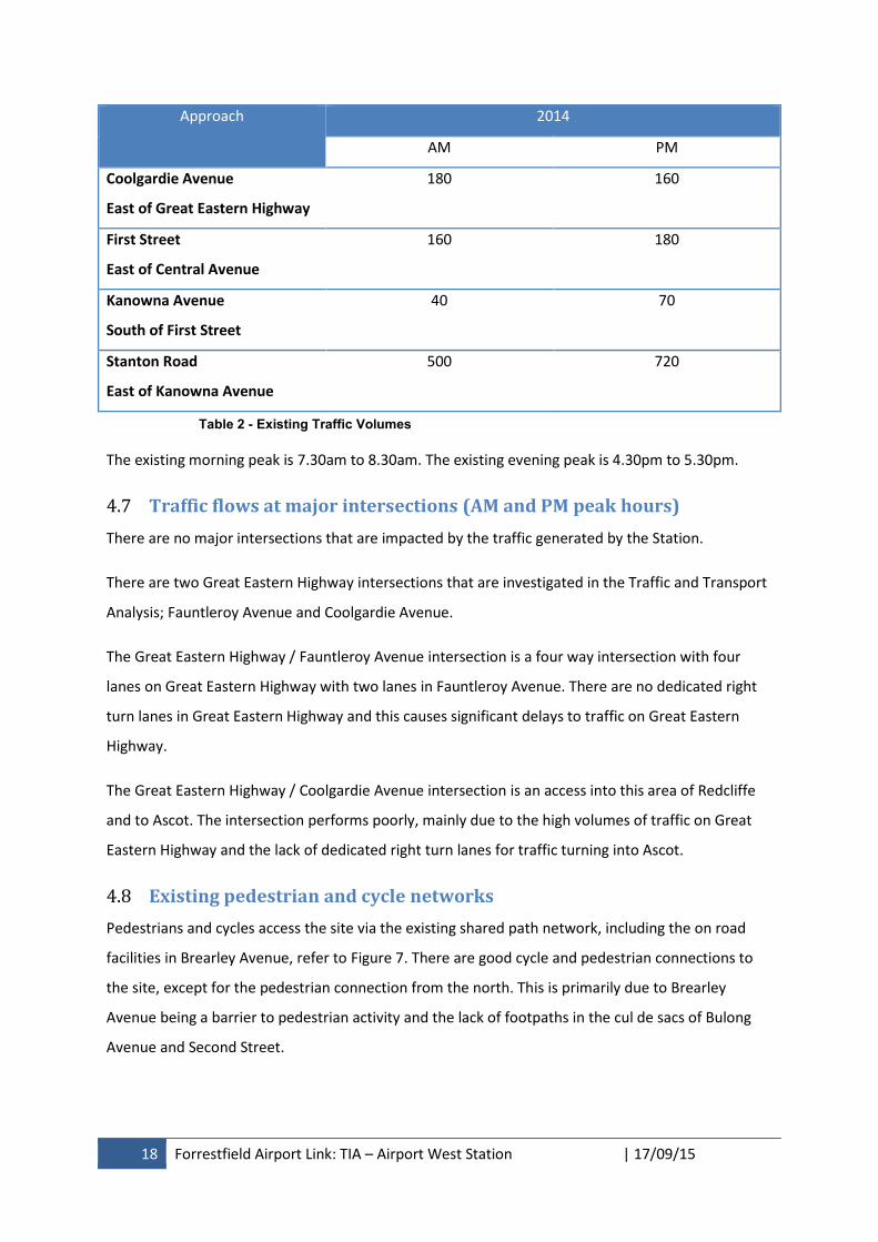
18 Forrestfield Airport Link: TIA – Airport West Station | 17/09/15
Approach 2014
AM PM
Coolgardie Avenue
East of Great Eastern Highway
180 160
First Street
East of Central Avenue
160 180
Kanowna Avenue
South of First Street
40 70
Stanton Road
East of Kanowna Avenue
500 720
Table 2 - Existing Traffic Volumes
The existing morning peak is 7.30am to 8.30am. The existing evening peak is 4.30pm to 5.30pm.
4.7 Traffic flows at major intersections (AM and PM peak hours)
There are no major intersections that are impacted by the traffic generated by the Station.
There are two Great Eastern Highway intersections that are investigated in the Traffic and Transport
Analysis; Fauntleroy Avenue and Coolgardie Avenue.
The Great Eastern Highway / Fauntleroy Avenue intersection is a four way intersection with four
lanes on Great Eastern Highway with two lanes in Fauntleroy Avenue. There are no dedicated right
turn lanes in Great Eastern Highway and this causes significant delays to traffic on Great Eastern
Highway.
The Great Eastern Highway / Coolgardie Avenue intersection is an access into this area of Redcliffe
and to Ascot. The intersection performs poorly, mainly due to the high volumes of traffic on Great
Eastern Highway and the lack of dedicated right turn lanes for traffic turning into Ascot.
4.8 Existing pedestrian and cycle networks
Pedestrians and cycles access the site via the existing shared path network, including the on road
facilities in Brearley Avenue, refer to Figure 7. There are good cycle and pedestrian connections to
the site, except for the pedestrian connection from the north. This is primarily due to Brearley
Avenue being a barrier to pedestrian activity and the lack of footpaths in the cul de sacs of Bulong
Avenue and Second Street.

19 Forrestfield Airport Link: TIA – Airport West Station | 17/09/15
Figure 7 – Pedestrian and Cycle Network
4.9 Existing public transport services surrounding the development
4.9.1 Local Services
Currently Belmont, Redcliffe and Cloverdale are served by sixteen bus routes:
Route 36 Midland Station to Perth via Great Eastern Hwy (Daily full time service)
Route 37 Airport T3/T4 to Kings Park via Perth (Daily full time high frequency service)
Route 38 Cloverdale to Perth (Monday to Friday daytime service)
Route 39 Redcliffe to Perth (Daily full time service)
Route 98 CircleRoute service – Clockwise (Daily full time high frequency service)
Route 99 CircleRoute service – Anti-clockwise (Daily full time high frequency service)
Route 284 Belmont Forum to Curtin University via Albany Hwy (Weekday limited shopper
service)
Route 285 Belmont Forum to Oats Street Station via Kewdale ((Weekday limited peak
service)
Route 286 Forrestfield to Perth via Belmont Forum (Weekday limited peak service)
Route 287 Forrestfield to Perth via Belmont Forum (Weekday limited peak service)
Proposed Station
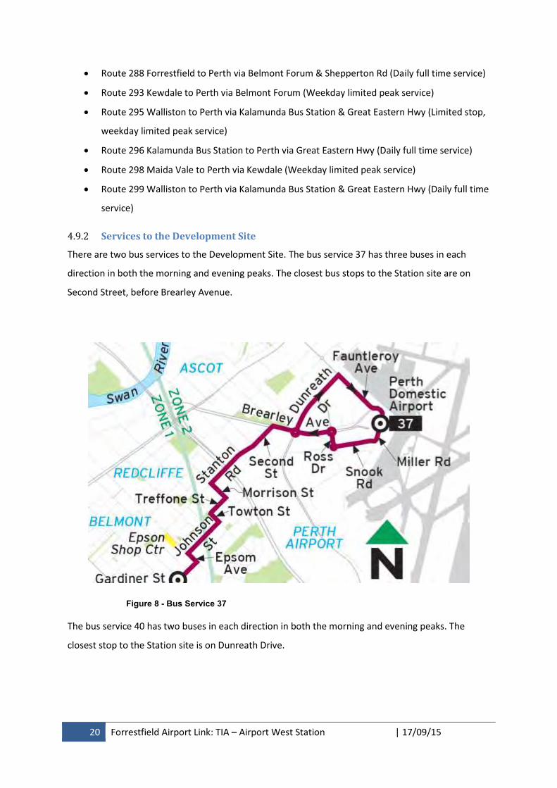
20 Forrestfield Airport Link: TIA – Airport West Station | 17/09/15
Route 288 Forrestfield to Perth via Belmont Forum & Shepperton Rd (Daily full time service)
Route 293 Kewdale to Perth via Belmont Forum (Weekday limited peak service)
Route 295 Walliston to Perth via Kalamunda Bus Station & Great Eastern Hwy (Limited stop,
weekday limited peak service)
Route 296 Kalamunda Bus Station to Perth via Great Eastern Hwy (Daily full time service)
Route 298 Maida Vale to Perth via Kewdale (Weekday limited peak service)
Route 299 Walliston to Perth via Kalamunda Bus Station & Great Eastern Hwy (Daily full time
service)
4.9.2 Services to the Development Site
There are two bus services to the Development Site. The bus service 37 has three buses in each
direction in both the morning and evening peaks. The closest bus stops to the Station site are on
Second Street, before Brearley Avenue.
Figure 8 - Bus Service 37
The bus service 40 has two buses in each direction in both the morning and evening peaks. The
closest stop to the Station site is on Dunreath Drive.
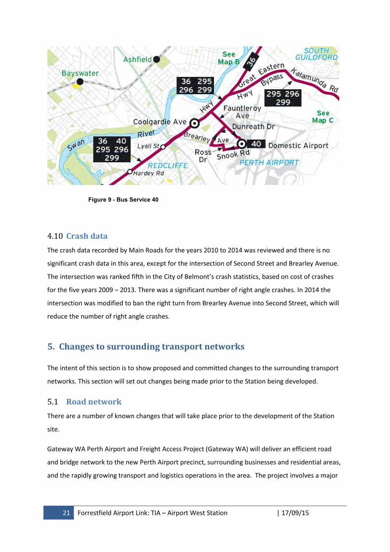
21 Forrestfield Airport Link: TIA – Airport West Station | 17/09/15
Figure 9 - Bus Service 40
4.10 Crash data
The crash data recorded by Main Roads for the years 2010 to 2014 was reviewed and there is no
significant crash data in this area, except for the intersection of Second Street and Brearley Avenue.
The intersection was ranked fifth in the City of Belmont’s crash statistics, based on cost of crashes
for the five years 2009 – 2013. There was a significant number of right angle crashes. In 2014 the
intersection was modified to ban the right turn from Brearley Avenue into Second Street, which will
reduce the number of right angle crashes.
5. Changes to surrounding transport networks
The intent of this section is to show proposed and committed changes to the surrounding transport
networks. This section will set out changes being made prior to the Station being developed.
5.1 Road network
There are a number of known changes that will take place prior to the development of the Station
site.
Gateway WA Perth Airport and Freight Access Project (Gateway WA) will deliver an efficient road
and bridge network to the new Perth Airport precinct, surrounding businesses and residential areas,
and the rapidly growing transport and logistics operations in the area. The project involves a major
22 Forrestfield Airport Link: TIA – Airport West Station | 17/09/15
upgrade of Tonkin Highway (between Great Eastern Highway and Roe Highway) and Leach Highway
(between Orrong Road and the Perth Airport).
A new grade separated interchange is being constructed at Tonkin Highway / Dunreath Drive. It is a
roundabout controlled interchange which will allow entry and exit from both directions on Tonkin
Highway to and from Dunreath Drive. When opened later this year the intersection will be the
primary access point for Airport West and Terminals 3 and 4. In the future it will be the main access
to the Consolidated Terminal.
Main Roads WA is currently designing an upgrade to the Great Eastern Highway / Fauntleroy Avenue
intersection. The upgrade will facilitate access for buses to the Airport West Station. There will be
widening of Great Eastern Highway to allow for dedicated right turn lanes. This will improve the
efficiency of the intersection. This work is programmed for completion by October 2016.
Following the opening of Gateway WA and the upgrade of the Fauntleroy intersection Brearley
Avenue will be closed between Great Eastern Highway and the PAPL boundary. Main Roads WA is
currently designing the modifications to the Brearley Avenue / Great Eastern Highway / Tonkin
Highway off ramp intersection. This work is programmed for completion by the end of 2016.
PAPL is currently designing a roundabout at the intersection of Snook Road and Dunreath Drive. The
roundabout is required due to changes in traffic patterns in the Airport that will be brought about by
the opening of Gateway WA and the staged consolidation of the Domestic and International
Terminals. This work is programmed for completion by October 2016.
5.1.1 PTA’s planned changes to the road network
Prior to the closure of Brearley Avenue the PTA, in association with PAPL and the City of Belmont,
will extend and upgrade Central Avenue from Second Street to Dunreath Drive in accordance with
the DA6 Vision Plan. Central Avenue will then connect to the PAPL’s proposed roundabout at Snook
Road. The extension of Central Avenue will become a major connection and should be classified as a
Local Distributor in line with the Second Street classification. The PTA requires this road, in the short
term, to allow the bus service 37 to access the Airport, following the closure of Brearley Avenue. In
the long term it will be part of a bus route for those buses that come from Fauntleroy Avenue into
the Station. It will also provide access to the park and ride, and kiss and ride, car parks.
With the opening of the Central Avenue extension and the closure of Brearley Avenue the section of
Second Street, from Central Avenue to Brearley Avenue, will be closed. The Central Avenue / Second
Street intersection then becomes a T-intersection.
23 Forrestfield Airport Link: TIA – Airport West Station | 17/09/15
5.1.2 The City of Belmont’s planned changes to the road network
As part of the DA6 development the City has the opportunity to restore a grid pattern and to provide
better connectivity in DA6. The following changes are proposed within DA6 by the year 2021,
however these projects are currently unfunded:
To support the land uses around the Station the City is proposing to connect Bulong Avenue
with Second Street. This allows traffic to circulate around Coolgardie and Bulong Avenues
but is subject to the purchase of private land.
To support the grid pattern the City is proposing to connect Central Avenue across the
existing Brearley Avenue road reserve, following the closure of Brearley Avenue.
A new road is proposed by the City to join Boulder Avenue with Kanowna Avenue, north of
First Street across the existing Brearley Avenue road reserve, to provide a vital connection to
Boulder Avenue, which is currently left out only at Great Eastern Highway.
The City of Belmont is also requesting the upgrade of the Great Eastern Highway / Coolgardie
Avenue to facilitate access into DA6. This is currently unfunded and the timing of the upgrade is
unknown.
5.2 Pedestrian and cycle networks and crossing facilities
The City of Belmont’s Local Bike Plan 2013-2018 was prepared in 2013 and is still current. The Bike
Plan suggests that in Fauntleroy Avenue, from Redcliffe Road to Brearley Avenue:
the southern footpath could be widened and upgraded to shared path standards. However,
this may not be possible along the full length due to the presence of street trees and has the
disadvantage of not connecting directly with the existing path on the eastern side of
Fauntleroy Avenue, north/west of Great Eastern Highway, and additional driveway crossings.
With the proposed upgrade to the Fauntleroy Avenue / Great Eastern Highway intersection there
will be improved crossing facilities at the intersection. The City of Belmont has committed to
seeking funding through the Department of Transport’s Connecting Stations Program for this path
from Redcliffe Road to Brearley Avenue. It is intended that the path would be constructed by the
City prior to the Station opening.
The Local Bike Plan looks at the timeframe to 2018, which is before the Airport West Station will be
opened. The Plan will be updated prior to the opening and will consider the localised network
around Airport West Station.
24 Forrestfield Airport Link: TIA – Airport West Station | 17/09/15
5.3 Public transport services
There are no planned changes to the public transport services prior to the Station opening.
6. Integration with surrounding area
The intent of this section is to identify how well the proposed development integrates with the
surrounding land uses with respect to transport links and accessibility. This is a qualitative
assessment of the level of accessibility between the Station and the surrounding area.
6.1 Surrounding major attractors/generators
The major trip generator will be the residential land surrounding the Station. The residents will be
attracted to the Station, primarily for the journey to work. The majority of these trips will be by bus,
bicycle or on foot.
The major trip attractor from the Station will be the Perth Airport West Precinct for workers, refer to
the Perth Airport Master Plan 2014. At opening there will be few workers but as the business park
within the Perth Airport West Precinct is developed the bus and rail passenger numbers will
increase.
6.2 Proposed changes to land uses within 1200m
Perth Airport comprises a total of 2,105ha and attracts approximately 17,800 employees to the site
daily. The Perth Airport Draft Master Plan 2014 states that by 2019 the number of employees is
expected to grow to 23,860. The Airport West Precinct provides a range of aviation support facilities
and associated ground transport as well as complementary non-aviation commercial developments.
Over time, limited office, retail and bulky goods may be provided.
The implementation of the DA6 Vision Plan will also see an intensification of land use surrounding
the Station with high rise mixed use development. The Station will allow this land to develop as a
TOD.
6.3 Travel desire lines from development to these attractors/generators
The travel desire lines to the Station will depend on the arriving transport mode. The PTA provides
priority to the modes in the following order:
1. Pedestrians
2. Cyclists
3. Bus Passengers
25 Forrestfield Airport Link: TIA – Airport West Station | 17/09/15
4. Private vehicles
a. Kiss and Ride
b. Park and Ride
Pedestrians who are attracted to the Station will filter through the neighbourhood streets with no
distinct desire lines. There is pedestrian access from both the north and south side of the Station.
The Airport West Precinct at the Airport will generate a desire line along the northern edge of the
Station towards Dunreath Drive. At the Station opening there will be a heavy right turn movement
from Dunreath Drive, south, into Brearley Avenue, east, and so crossing Dunreath Drive is preferable
to the north of the existing roundabout.
Cyclists will be attracted to the southern side of the Station, as that is where the secure bike parking
will be provided.
For bus passengers the routes will be fixed along Second Street and Dunreath Drive. The bus station
is directly adjacent to the train station so the passengers’ desire lines will be directly into the train
station and will not require the crossing of any roads.
Vehicles using the formal kiss and ride facility will use Central Avenue. Informal kiss and ride will be
provided in the surrounding roads.
Vehicles using the park and ride car park will use Second Street or Dunreath Drive to access the car
park. The pedestrian desire lines from the car park will be along the eastern side of Second Street or
the western side of the kiss and ride road. All pedestrians from the car park will need to cross
Central Avenue.
6.4 Adequacy of existing transport networks
6.4.1 Pedestrian and cycle networks
The pedestrian network surrounding the site is based on low levels of pedestrians in a residential
neighbourhood. In many of the small cul de sacs there are no footpaths. The network needs to make
connection into the Station and to serve the desire lines from the parking. The situation for the
cyclists is similar.
There are gaps in the existing footpath network in Bulong Avenue and Second Street on the north
side of the Station. Second Street, to the south of the Station, does not have a footpath in the
eastern verge. The existing Central Avenue, adjacent to the Development Site, has no footpaths.
There is an existing on road cycle lane in Brearley Avenue but no footpath.
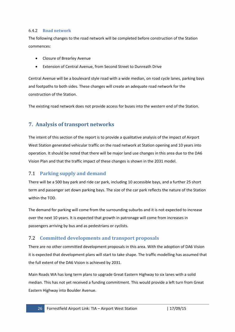
26 Forrestfield Airport Link: TIA – Airport West Station | 17/09/15
6.4.2 Road network
The following changes to the road network will be completed before construction of the Station
commences:
Closure of Brearley Avenue
Extension of Central Avenue, from Second Street to Dunreath Drive
Central Avenue will be a boulevard style road with a wide median, on road cycle lanes, parking bays
and footpaths to both sides. These changes will create an adequate road network for the
construction of the Station.
The existing road network does not provide access for buses into the western end of the Station.
7. Analysis of transport networks
The intent of this section of the report is to provide a qualitative analysis of the impact of Airport
West Station generated vehicular traffic on the road network at Station opening and 10 years into
operation. It should be noted that there will be major land use changes in this area due to the DA6
Vision Plan and that the traffic impact of these changes is shown in the 2031 model.
7.1 Parking supply and demand
There will be a 500 bay park and ride car park, including 10 accessible bays, and a further 25 short
term and passenger set down parking bays. The size of the car park reflects the nature of the Station
within the TOD.
The demand for parking will come from the surrounding suburbs and it is not expected to increase
over the next 10 years. It is expected that growth in patronage will come from increases in
passengers arriving by bus and as pedestrians or cyclists.
7.2 Committed developments and transport proposals
There are no other committed development proposals in this area. With the adoption of DA6 Vision
it is expected that development plans will start to take shape. The traffic modelling has assumed that
the full extent of the DA6 Vision is achieved by 2031.
Main Roads WA has long term plans to upgrade Great Eastern Highway to six lanes with a solid
median. This has not yet received a funding commitment. This would provide a left turn from Great
Eastern Highway into Boulder Avenue.
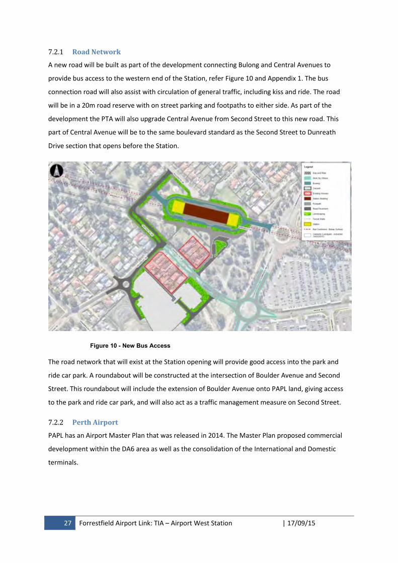
27 Forrestfield Airport Link: TIA – Airport West Station | 17/09/15
7.2.1 Road Network
A new road will be built as part of the development connecting Bulong and Central Avenues to
provide bus access to the western end of the Station, refer Figure 10 and Appendix 1. The bus
connection road will also assist with circulation of general traffic, including kiss and ride. The road
will be in a 20m road reserve with on street parking and footpaths to either side. As part of the
development the PTA will also upgrade Central Avenue from Second Street to this new road. This
part of Central Avenue will be to the same boulevard standard as the Second Street to Dunreath
Drive section that opens before the Station.
Figure 10 - New Bus Access
The road network that will exist at the Station opening will provide good access into the park and
ride car park. A roundabout will be constructed at the intersection of Boulder Avenue and Second
Street. This roundabout will include the extension of Boulder Avenue onto PAPL land, giving access
to the park and ride car park, and will also act as a traffic management measure on Second Street.
7.2.2 Perth Airport
PAPL has an Airport Master Plan that was released in 2014. The Master Plan proposed commercial
development within the DA6 area as well as the consolidation of the International and Domestic
terminals.
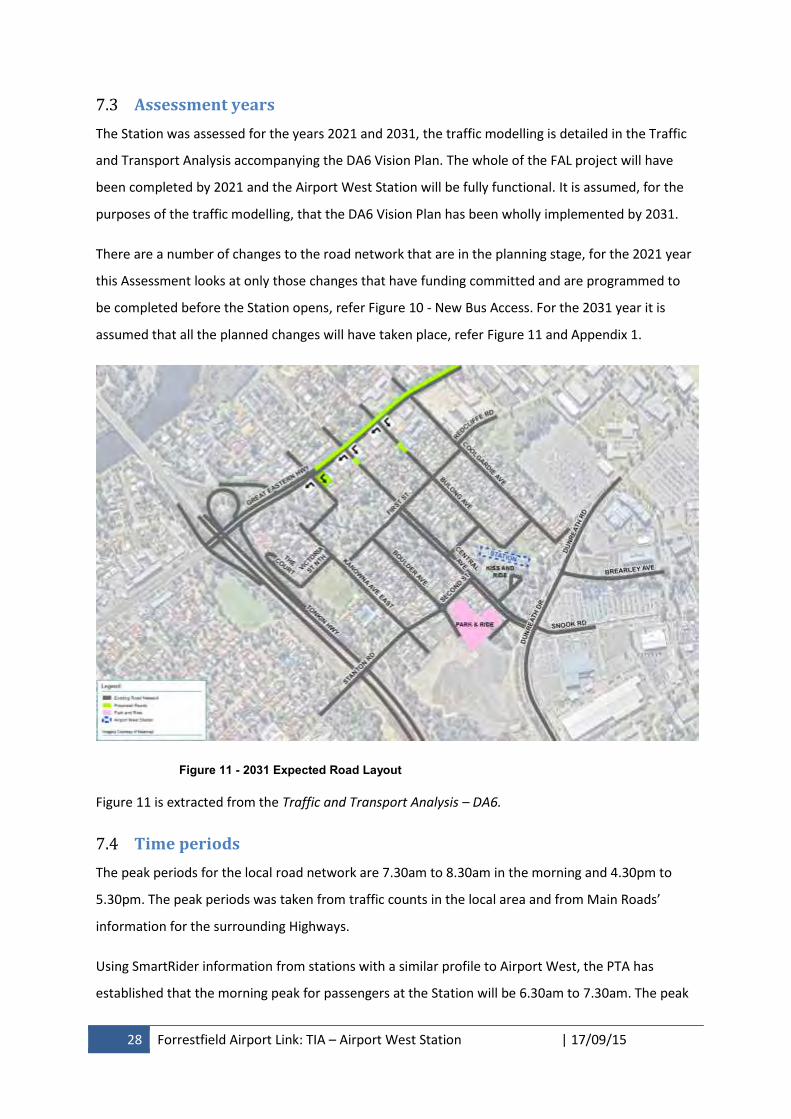
28 Forrestfield Airport Link: TIA – Airport West Station | 17/09/15
7.3 Assessment years
The Station was assessed for the years 2021 and 2031, the traffic modelling is detailed in the Traffic
and Transport Analysis accompanying the DA6 Vision Plan. The whole of the FAL project will have
been completed by 2021 and the Airport West Station will be fully functional. It is assumed, for the
purposes of the traffic modelling, that the DA6 Vision Plan has been wholly implemented by 2031.
There are a number of changes to the road network that are in the planning stage, for the 2021 year
this Assessment looks at only those changes that have funding committed and are programmed to
be completed before the Station opens, refer Figure 10 - New Bus Access. For the 2031 year it is
assumed that all the planned changes will have taken place, refer Figure 11 and Appendix 1.
Figure 11 - 2031 Expected Road Layout
Figure 11 is extracted from the Traffic and Transport Analysis – DA6.
7.4 Time periods
The peak periods for the local road network are 7.30am to 8.30am in the morning and 4.30pm to
5.30pm. The peak periods was taken from traffic counts in the local area and from Main Roads’
information for the surrounding Highways.
Using SmartRider information from stations with a similar profile to Airport West, the PTA has
established that the morning peak for passengers at the Station will be 6.30am to 7.30am. The peak
29 Forrestfield Airport Link: TIA – Airport West Station | 17/09/15
is very pronounced and the park and ride car park will be full before 8.00am. The evening peak runs
from 3.00pm to 6.00pm, with 4.30pm to 5.30pm being the peak hour.
7.5 Development and distribution of generated traffic
7.5.1 Trip generation
The PTA has estimated the number of one way boardings for 2021 year for the Airport West Station.
These boardings have then been distributed by mode as shown in Table 3. This mode share was then
applied in the traffic model, along with the assumed time periods of the trips, to give the vehicle trip
generation for 2021. The number of bus trips is based on Transperth’s planning for bus services to
the Station.
Mode Estimated One Way
Boardings in 2021
Morning Peak Evening Peak
Inbound Outbound Inbound Outbound
Bus transfers 1,000 28 28 28 28
Park and Ride 550 300 0 0 300
Kiss and Ride 300 200 200 200 200
Walking/Cycling 200 - - - -
Total 2,050 528 228 228 528
Table 3 – Vehicle Trip Generation 2021
A similar exercise was then undertaken for the 2031 year, refer to Table 4. The size of the car park
remains the same and therefore has no increase in trip generation. The buses will now be full when
they arrive at the station but there would be no increase in the number of buses arriving.
Mode Estimated One Way
Boardings in 2031
Morning Peak Evening Peak
Inbound Outbound Inbound Outbound
Bus transfers 1,500 28 28 28 28
Park and Ride 550 300 0 0 300
Kiss and Ride 450 270 270 270 270
Walking/Cycling 500 - - - -
Total 3,000 598 298 298 598
Table 4 - Vehicle Trip Generation 2031
7.5.2 Trip distribution
An Aimsun hybrid model, containing both a microscopic and mesoscopic model area, has been built
for FAL. A hybrid model was chosen as it allows for individual vehicles, including buses and heavy
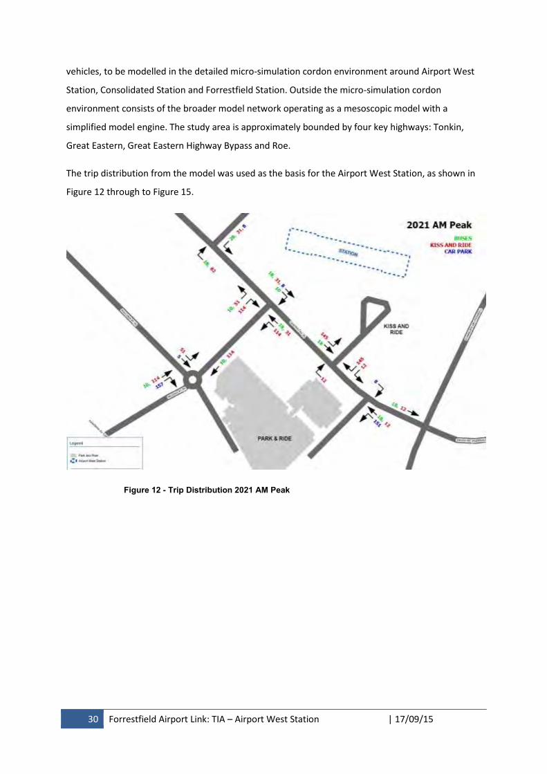
30 Forrestfield Airport Link: TIA – Airport West Station | 17/09/15
vehicles, to be modelled in the detailed micro-simulation cordon environment around Airport West
Station, Consolidated Station and Forrestfield Station. Outside the micro-simulation cordon
environment consists of the broader model network operating as a mesoscopic model with a
simplified model engine. The study area is approximately bounded by four key highways: Tonkin,
Great Eastern, Great Eastern Highway Bypass and Roe.
The trip distribution from the model was used as the basis for the Airport West Station, as shown in
Figure 12 through to Figure 15.
Figure 12 - Trip Distribution 2021 AM Peak
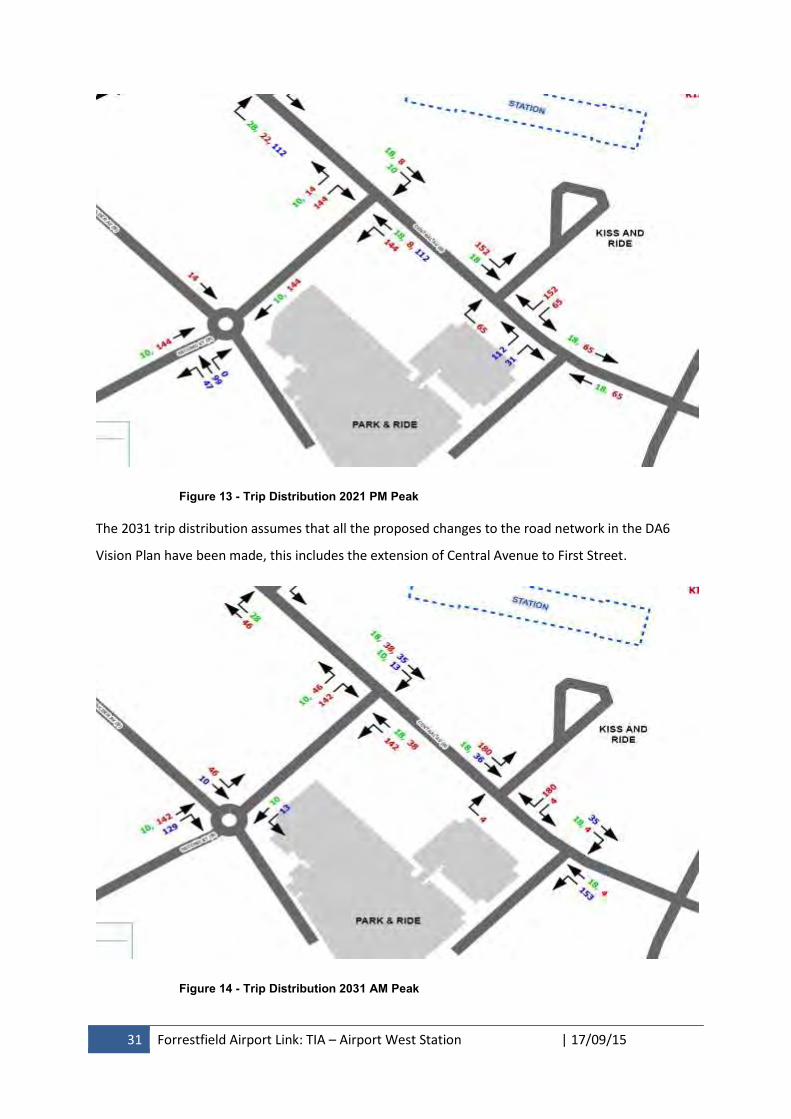
31 Forrestfield Airport Link: TIA – Airport West Station | 17/09/15
Figure 13 - Trip Distribution 2021 PM Peak
The 2031 trip distribution assumes that all the proposed changes to the road network in the DA6
Vision Plan have been made, this includes the extension of Central Avenue to First Street.
Figure 14 - Trip Distribution 2031 AM Peak
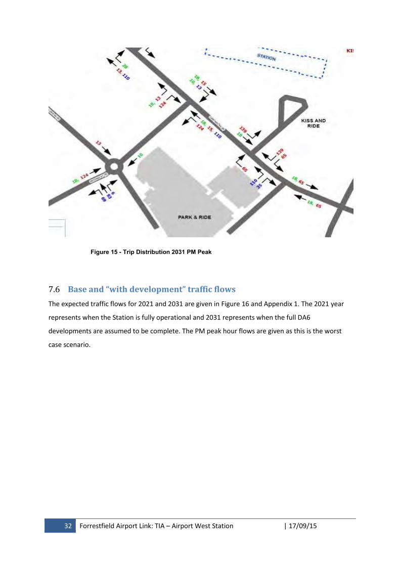
32 Forrestfield Airport Link: TIA – Airport West Station | 17/09/15
Figure 15 - Trip Distribution 2031 PM Peak
7.6 Base and “with development” traffic flows
The expected traffic flows for 2021 and 2031 are given in Figure 16 and Appendix 1. The 2021 year
represents when the Station is fully operational and 2031 represents when the full DA6
developments are assumed to be complete. The PM peak hour flows are given as this is the worst
case scenario.
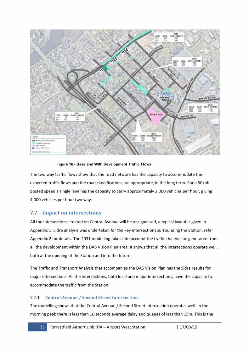
33 Forrestfield Airport Link: TIA – Airport West Station | 17/09/15
Figure 16 - Base and With Development Traffic Flows
The two way traffic flows show that the road network has the capacity to accommodate the
expected traffic flows and the road classifications are appropriate, in the long term. For a 50kph
posted speed a single lane has the capacity to carry approximately 2,000 vehicles per hour, giving
4,000 vehicles per hour two way.
7.7 Impact on intersections
All the intersections created on Central Avenue will be unsignalised, a typical layout is given in
Appendix 1. Sidra analysis was undertaken for the key intersections surrounding the Station, refer
Appendix 2 for details. The 2031 modelling takes into account the traffic that will be generated from
all the development within the DA6 Vision Plan area. It shows that all the intersections operate well,
both at the opening of the Station and into the future.
The Traffic and Transport Analysis that accompanies the DA6 Vision Plan has the Sidra results for
major intersections. All the intersections, both local and major intersections, have the capacity to
accommodate the traffic from the Station.
7.7.1 Central Avenue / Second Street Intersection
The modelling shows that the Central Avenue / Second Street Intersection operates well. In the
morning peak there is less than 10 seconds average delay and queues of less than 15m. This is the
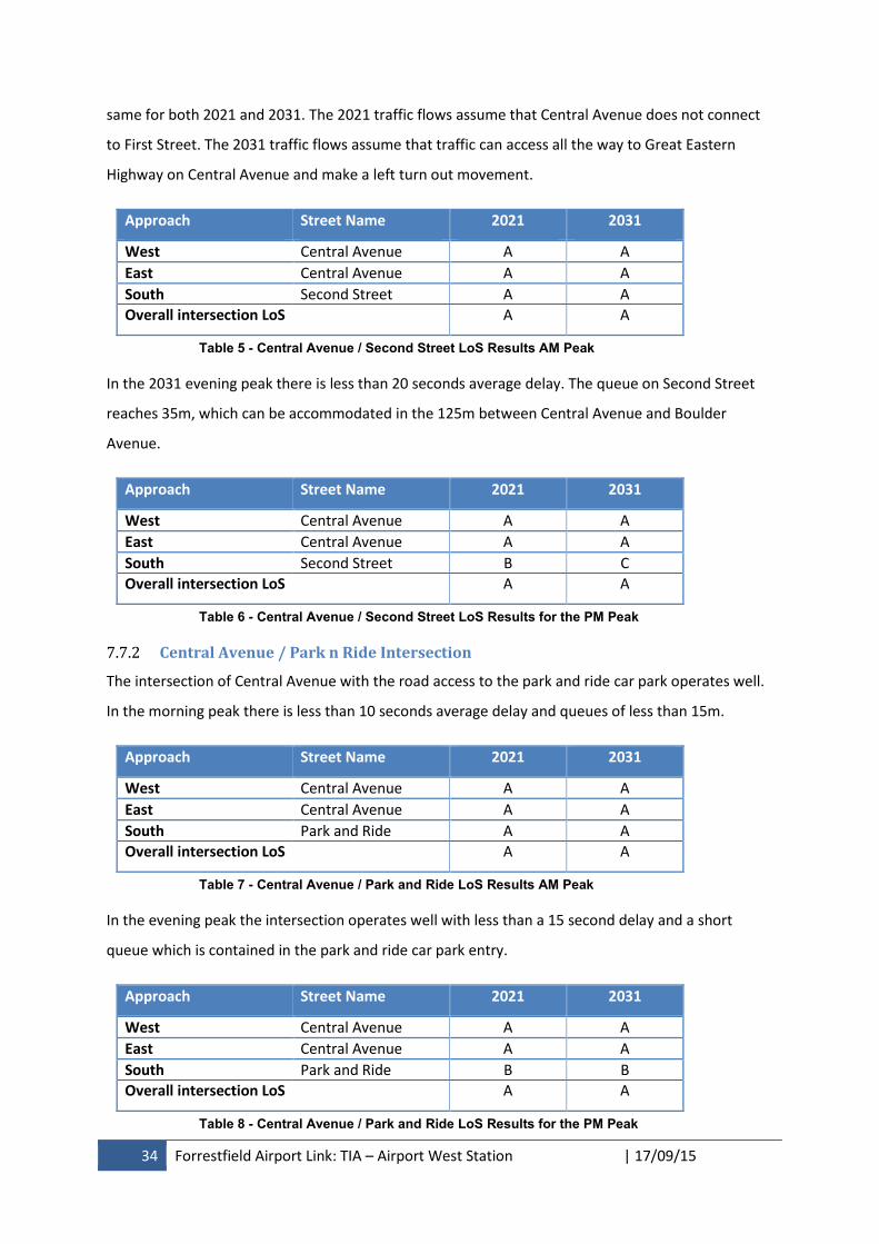
34 Forrestfield Airport Link: TIA – Airport West Station | 17/09/15
same for both 2021 and 2031. The 2021 traffic flows assume that Central Avenue does not connect
to First Street. The 2031 traffic flows assume that traffic can access all the way to Great Eastern
Highway on Central Avenue and make a left turn out movement.
Approach Street Name 2021 2031
West Central Avenue A A
East Central Avenue A A
South Second Street A A
Overall intersection LoS A A
Table 5 - Central Avenue / Second Street LoS Results AM Peak
In the 2031 evening peak there is less than 20 seconds average delay. The queue on Second Street
reaches 35m, which can be accommodated in the 125m between Central Avenue and Boulder
Avenue.
Approach Street Name 2021 2031
West Central Avenue A A
East Central Avenue A A
South Second Street B C
Overall intersection LoS A A
Table 6 - Central Avenue / Second Street LoS Results for the PM Peak
7.7.2 Central Avenue / Park n Ride Intersection
The intersection of Central Avenue with the road access to the park and ride car park operates well.
In the morning peak there is less than 10 seconds average delay and queues of less than 15m.
Approach Street Name 2021 2031
West Central Avenue A A
East Central Avenue A A
South Park and Ride A A
Overall intersection LoS A A
Table 7 - Central Avenue / Park and Ride LoS Results AM Peak
In the evening peak the intersection operates well with less than a 15 second delay and a short
queue which is contained in the park and ride car park entry.
Approach Street Name 2021 2031
West Central Avenue A A
East Central Avenue A A
South Park and Ride B B
Overall intersection LoS A A
Table 8 - Central Avenue / Park and Ride LoS Results for the PM Peak
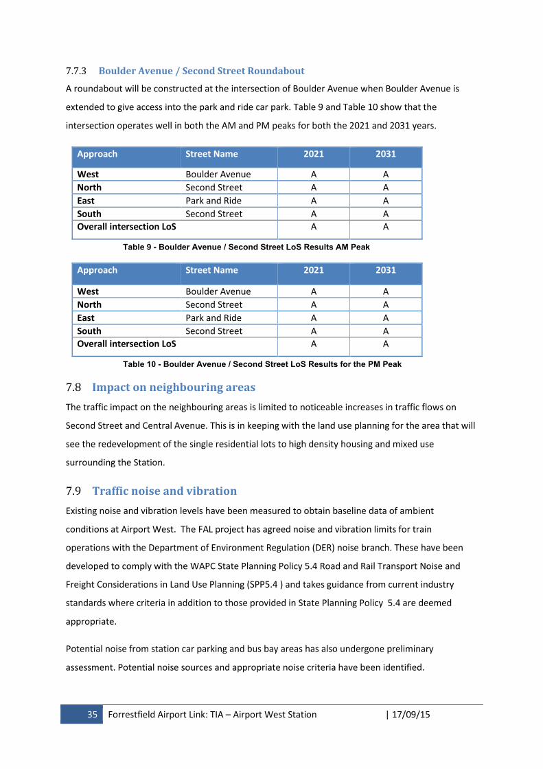
35 Forrestfield Airport Link: TIA – Airport West Station | 17/09/15
7.7.3 Boulder Avenue / Second Street Roundabout
A roundabout will be constructed at the intersection of Boulder Avenue when Boulder Avenue is
extended to give access into the park and ride car park. Table 9 and Table 10 show that the
intersection operates well in both the AM and PM peaks for both the 2021 and 2031 years.
Approach Street Name 2021 2031
West Boulder Avenue A A
North Second Street A A
East Park and Ride A A
South Second Street A A
Overall intersection LoS A A
Table 9 - Boulder Avenue / Second Street LoS Results AM Peak
Approach Street Name 2021 2031
West Boulder Avenue A A
North Second Street A A
East Park and Ride A A
South Second Street A A
Overall intersection LoS A A
Table 10 - Boulder Avenue / Second Street LoS Results for the PM Peak
7.8 Impact on neighbouring areas
The traffic impact on the neighbouring areas is limited to noticeable increases in traffic flows on
Second Street and Central Avenue. This is in keeping with the land use planning for the area that will
see the redevelopment of the single residential lots to high density housing and mixed use
surrounding the Station.
7.9 Traffic noise and vibration
Existing noise and vibration levels have been measured to obtain baseline data of ambient
conditions at Airport West. The FAL project has agreed noise and vibration limits for train
operations with the Department of Environment Regulation (DER) noise branch. These have been
developed to comply with the WAPC State Planning Policy 5.4 Road and Rail Transport Noise and
Freight Considerations in Land Use Planning (SPP5.4 ) and takes guidance from current industry
standards where criteria in addition to those provided in State Planning Policy 5.4 are deemed
appropriate.
Potential noise from station car parking and bus bay areas has also undergone preliminary
assessment. Potential noise sources and appropriate noise criteria have been identified.
36 Forrestfield Airport Link: TIA – Airport West Station | 17/09/15
Full details are contained in Forrestfield-Airport Link Noise and Vibration Management Construction
and Operation Environment Impact Report, SLR February 2015.
All Transperth buses comply with Australian Design Standards (including those relating to noise
levels) and are required to undergo an annual inspection by the Department of Transport to ensure
that they are appropriately maintained and registered for use on Western Australian roads.
Transperth always endeavours to keep noise levels at its bus station facilities to a minimum and has
directed its contracted bus service providers to ensure bus drivers do not allow buses to idle for
excessive periods of time when at a terminus.
7.10 Road safety
There are no existing road safety issues that need addressing. Road safety audits will be conducted
for all designs in accordance with Austroads Guide to Road Safety Part 6: Road Safety Audit.
7.11 Public transport access
The suburbs of Belmont, Redcliffe and Cloverdale are the most densely populated suburbs within the
proximity of the Station and are therefore the most extensively served in terms of the Transperth
bus network. Service frequency on many routes is high with the majority of services connecting
people directly to the Perth CBD and or the Armadale, Thornlie or Midland train lines.
It is anticipated with the introduction of services on the FAL a revised bus network will improve
connectivity and travel time reliability to Perth for residents particularly for residents east of
Belmont Forum shopping centre with access to the FAL at Airport West Station and to a lesser extent
at Consolidated Airport Station.
Route 35, a new service will provide a frequent and high capacity service along Great Eastern Hwy
between Airport West Station and Perth. This route will effectively replace the frequency and
capacity lost along this activity corridor by redirecting Routes 36, 295, 296 and 299 to the FAL and
the withdrawal of Route 40. Services will operate as a bi-directional feeder with residents closer to
Airport West Station likely to travel backwards to connect with rail for a faster journey to Perth.
Route 37, one of Perth’s most popular bus routes is proposed to operate on a largely unchanged,
alignment given the current route already terminates adjacent to Terminals 3 & 4 in the current
Domestic Airport precinct. The route terminus will shift west to Airport West Station and will be
scheduled to connect where possible to Perth-bound trains (making the route a bi-directional
feeder). The high level of contraflow service already operating on this route negates the need for
any substantial service upgrade once rail services commence.
37 Forrestfield Airport Link: TIA – Airport West Station | 17/09/15
Route 39 will undergo a route extension to Airport West Station and operate as a bidirectional
feeder, dramatically improving journey times to Perth for residents within Redcliffe and Cloverdale.
The Abernethy Rd / Wright St corridor currently served by Routes 38, 288 and 298, will instead be
served by a combination of Routes 38, 286 and 287 providing a slightly higher level of service than is
currently provided today.
New Route 288 will be introduced between Oats St Station and Consolidated Airport Station via
Belmont Forum providing improved access to rail for Cloverdale residents, as well as the commercial
and light industry within the consolidated airport precinct.
Routes 37, 38, 98, 99, 284 and 285 would also continue to operate under the proposed FAL
supporting bus network, albeit with no or only minor changes to their routes or service headway.
It should be noted that the proposed FAL supporting bus network is subject to resources and an
extensive community consultation process to be conducted approximately 12 months prior to train
services commencing.
The buses coming into the Station will give direct, safe and convenient access and the location of the
bus stops eliminates the need for passengers to cross any roads when transferring between the bus
and rail. The bus stops will all be located under the Station roof and will be well lit.
8. Analysis of pedestrian and cycle networks
The purpose of this section of the report is to show the existing level of access and amenity for
pedestrians and cyclists, to identify gaps, and to describe any improvements.
The layout of the station allows for bus passengers to access the trains without having to cross any
roads, thereby maximising their safety. The bus station is a controlled low speed environment and
zebra crossings will be provided across the bus lanes to give priority to pedestrians. The crossings
will be located such that they align with the pedestrian desire lines and give proper sight lines for
bus drivers to the crossings.
8.1 Pedestrian access and amenity
This section combines the pedestrian information provided earlier in a number of separate sections
into a single section. It therefore provides an inventory of existing and proposed pedestrian access
and amenity.
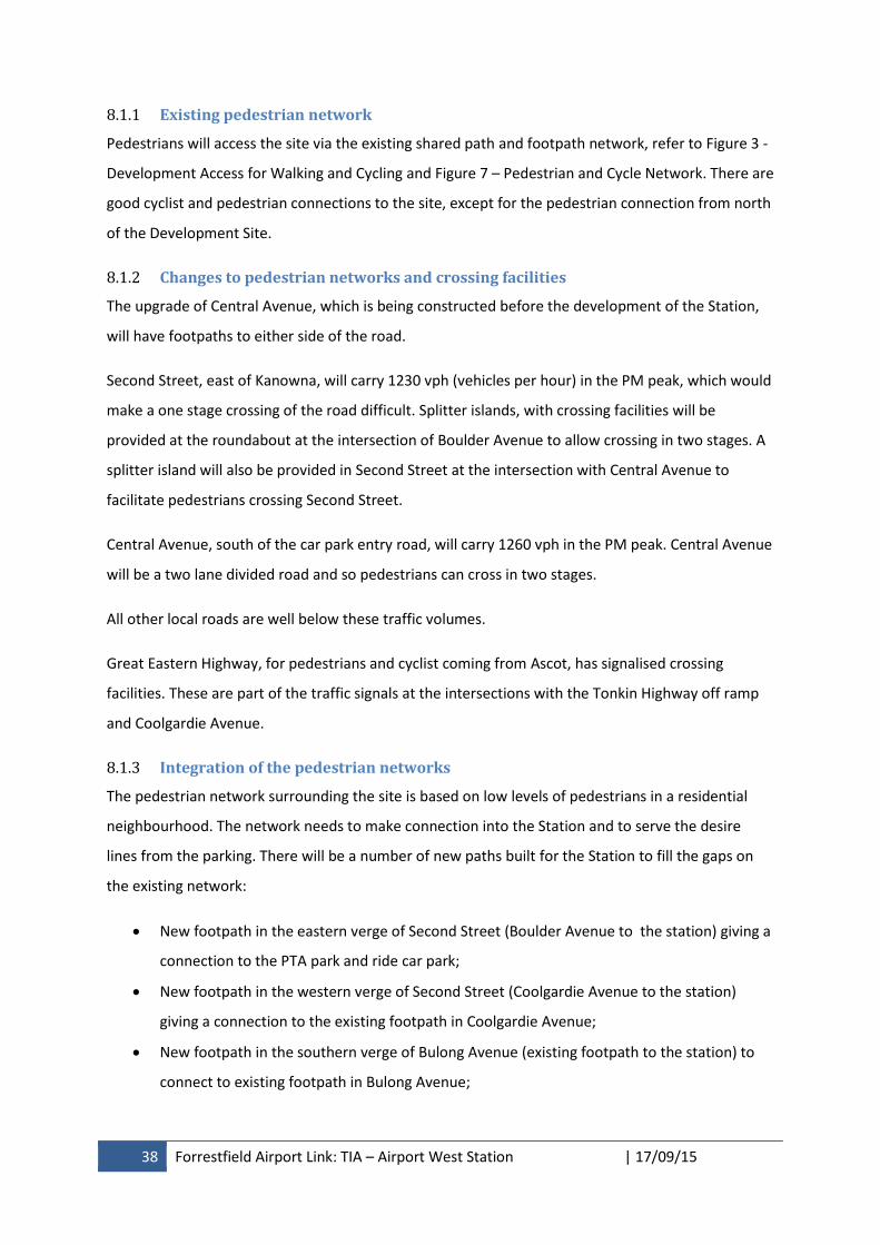
38 Forrestfield Airport Link: TIA – Airport West Station | 17/09/15
8.1.1 Existing pedestrian network
Pedestrians will access the site via the existing shared path and footpath network, refer to Figure 3 -
Development Access for Walking and Cycling and Figure 7 – Pedestrian and Cycle Network. There are
good cyclist and pedestrian connections to the site, except for the pedestrian connection from north
of the Development Site.
8.1.2 Changes to pedestrian networks and crossing facilities
The upgrade of Central Avenue, which is being constructed before the development of the Station,
will have footpaths to either side of the road.
Second Street, east of Kanowna, will carry 1230 vph (vehicles per hour) in the PM peak, which would
make a one stage crossing of the road difficult. Splitter islands, with crossing facilities will be
provided at the roundabout at the intersection of Boulder Avenue to allow crossing in two stages. A
splitter island will also be provided in Second Street at the intersection with Central Avenue to
facilitate pedestrians crossing Second Street.
Central Avenue, south of the car park entry road, will carry 1260 vph in the PM peak. Central Avenue
will be a two lane divided road and so pedestrians can cross in two stages.
All other local roads are well below these traffic volumes.
Great Eastern Highway, for pedestrians and cyclist coming from Ascot, has signalised crossing
facilities. These are part of the traffic signals at the intersections with the Tonkin Highway off ramp
and Coolgardie Avenue.
8.1.3 Integration of the pedestrian networks
The pedestrian network surrounding the site is based on low levels of pedestrians in a residential
neighbourhood. The network needs to make connection into the Station and to serve the desire
lines from the parking. There will be a number of new paths built for the Station to fill the gaps on
the existing network:
New footpath in the eastern verge of Second Street (Boulder Avenue to the station) giving a
connection to the PTA park and ride car park;
New footpath in the western verge of Second Street (Coolgardie Avenue to the station)
giving a connection to the existing footpath in Coolgardie Avenue;
New footpath in the southern verge of Bulong Avenue (existing footpath to the station) to
connect to existing footpath in Bulong Avenue;

39 Forrestfield Airport Link: TIA – Airport West Station | 17/09/15
New shared path in the northern verge of Brearley Avenue (the station to Dunreath Drive) to
connect the station to the existing crossing of Dunreath Drive, north of the Brearley Avenue
Roundabout; and
New footpaths to either side of Central Avenue (Second Street to the new bus access road)
to extend the footpath network.
The paths up to and through the Station will be arranged so that there is minimal interaction
between cyclists and pedestrians. The main pedestrian paths and connections are to the north of the
station and the bike lockers are on the south of the Station.
Pedestrian crossing facilities will be provided at the appropriate points, refer to Figure 3 -
Development Access for Walking and Cycling and Figure 7 – Pedestrian and Cycle Network. A typical
intersection layout for Central Avenue, with pedestrian crossings, is shown in Appendix 1.
8.1.4 Development pedestrian access arrangements
There are two pedestrian access points to the station, one on the northern side and one on the
southern side, refer Figure 3 - Development Access for Walking and Cycling. The unpaid zone in the
centre of the Station will allow pedestrians to walk through the Station, from north to south, without
passing through a fare gate. Passengers for the train will be able to access the platforms from fare
gates to one side of this walkway.
8.2 Cycle access and amenity
This section combines the cycle information provided earlier in a number of separate sections into a
single section. It therefore provides an inventory of existing and proposed cycle access and amenity.
8.2.1 Existing cycle network
Cyclists access the site via the existing shared path network, including the on road facilities in
Brearley Avenue, refer to Figure 3 - Development Access for Walking and Cycling and Figure 7 –
Pedestrian and Cycle Network. There are good cycle connections to the site.
8.2.2 Changes to cycle networks and crossing facilities
The City of Belmont’s Local Bike Plan 2013-2018 was prepared in 2013 and is still current. The Bike
Plan suggests that in Fauntleroy Avenue, from Redcliffe Road to Brearley Avenue:
the southern footpath could be widened and upgraded to shared path standards. However,
this may not be possible along the full length due to the presence of street trees and has the
disadvantage of not connecting directly with the existing path on the eastern side of
Fauntleroy Avenue, north/west of Great Eastern Highway, and additional driveway crossings.

40 Forrestfield Airport Link: TIA – Airport West Station | 17/09/15
With the proposed upgrade to the Fauntleroy Avenue / Great Eastern Highway intersection there
will be improved crossing facilities at the intersection. The City of Belmont has committed to
seeking funding through the Department of Transport’s Connecting Stations Program for this path
from Redcliffe Road to Brearley Avenue. It is intended that the path would be constructed by the
City prior to the Station opening.
The extension of Central Avenue, from Second Street to Dunreath Drive, will have on road cycle
lanes. These will be constructed before the construction of the Station commences. These cycle
lanes will allow cyclist that currently use Brearley Avenue to connect to Dunreath Drive without the
need to cycle through the Station precinct.
As part of the Gateway WA project Main Roads will be providing safe access for pedestrians and
cyclists for both local and commuter trips. There will be a PSP on the western side of Tonkin
Highway. This will have a number of connections to the shared path network in the area, including
Stanton Road. There will be a PSP at the Dunreath Drive interchange that will connect to the
Airport’s cycle network.
8.2.3 Integration of the cycle networks
The cycle network surrounding the site is based on a low density residential neighbourhood with
shared paths through the public open space, along with on road cycle lanes in Brearley Avenue. The
network needs to make connection into the Station and to connect with the surrounding network.
There will be a new shared path in the northern verge of Brearley Avenue (the Station to Dunreath
Drive) to connect the Station to the existing crossing of Dunreath Drive, north of the Brearley
Avenue Roundabout. This will connect into the shared path network on Dunreath Drive. There is an
existing shared path in the northern verge of Brearley Avenue (the Station to Great Eastern Highway)
that gives access to the west.
The upgrade of Central Avenue, Second Street to the bus access road, will have on road cycle lanes.
Ultimately this will provide on road cycling from Great Eastern Highway to Dunreath Drive.
The paths up to and through the Station will be arranged so that there is minimal interaction
between cyclists and pedestrians. The main pedestrian paths and connections are to the north of the
station and the bike lockers are on the south of the Station.
41 Forrestfield Airport Link: TIA – Airport West Station | 17/09/15
8.2.4 Development cycle access arrangements
There is an existing cycle path network on the streets surrounding the Station. This will be
supplemented by the construction of additional shared paths and on road cycle lanes, as well as
clear crossing points.
There will be secure parking for 90 bikes provided at the Station and a minimum of 10 U rails. There
will be no other end of trip facilities as it is unlikely that the Station will be the end of the trip for
cyclist as they will be transferring to the train or bus.
9. Conclusions
Airport West Station provides a great improvement in public transport for Belmont, Ascot, Redcliffe,
and Perth Airport. It will potentially remove an existing 4,100 trips from the road network in 2021,
and prevent a further 1,900 trips from being added to the network by 2031. The Station will also
allow for the creation of a TOD as the proposed mix use development and the business park
development on PAPL land, within walking distance, will give more balanced flows of passengers.
The layout of the Station allows for the safest and most efficient transfer of passengers from buses
to rail, which encourages public transport use.
The closure of Brearley Avenue, with the subsequent removal of 36,000 VPD from Redcliffe, allows
for the reinstatement of a grid pattern of roads. This allows local residents easy walking and cycling
access to the Station via the existing networks and new paths that have been proposed to fill any
gaps in the networks. The layout of the Station will be easily legible for pedestrians and cyclists with
two entry points. The Station will also allow pedestrians unpaid access through the Station so that
there is good connectivity between the land uses that will surround the Station.
Bus access to the bus station will be from a new road that will be created as part of the
development. This new road will be a public road and reinforces the grid pattern that is being re-
established. The extension and upgrading of Central Avenue will provide a local link onto Dunreath
Drive and a cycle route for cyclist accessing the Airport.
This Traffic Impact Assessment has looked at the existing situation of land use and road network
surrounding the Development Site. It has given details of the traffic related aspects of the
development and identified the desire lines for all modes of transport. A gap analysis was then
conducted to identify where new infrastructure is required. Details of how the development
addresses those gaps were also given.
42 Forrestfield Airport Link: TIA – Airport West Station | 17/09/15
This Traffic Impact Assessment has taken into consideration how the Station will operate at opening
and when all the land intensification related to DA6 has been completed. The known changes to the
road network that will take place before the Station opens and before DA6 is complete have been
taken into consideration. All the roads and intersections have the capacity to efficiently operate
without modification and the Station has a positive impact on transport in the area. The Station will:
• provide safe and efficient access for all modes;
• be well integrated with the surrounding land uses;
• not adversely impact on the surrounding land uses; and
• not adversely impact on the surrounding transport networks and the users of those
networks.

Appendix 1 – Figures
Figure 2 - Airport West Station Location
Figure 3 - Development Access for Walking and Cycling
Figure 4 - Development Access for Public Transport
Figure 5 - Development Access for Private Vehicles
Figure 6 - Existing Road Network
Figure 11 - 2031 Expected Road Layout
Figure 12 - Trip Distribution 2021 AM Peak
Figure 13 - Trip Distribution 2021 PM Peak
Figure 14 - Trip Distribution 2031 AM Peak
Figure 15 - Trip Distribution 2031 PM Peak
Figure 16 - Base and With Development Traffic Flows

44 Forrestfield Airport Link: TIA – Airport West Station | 17/09/15
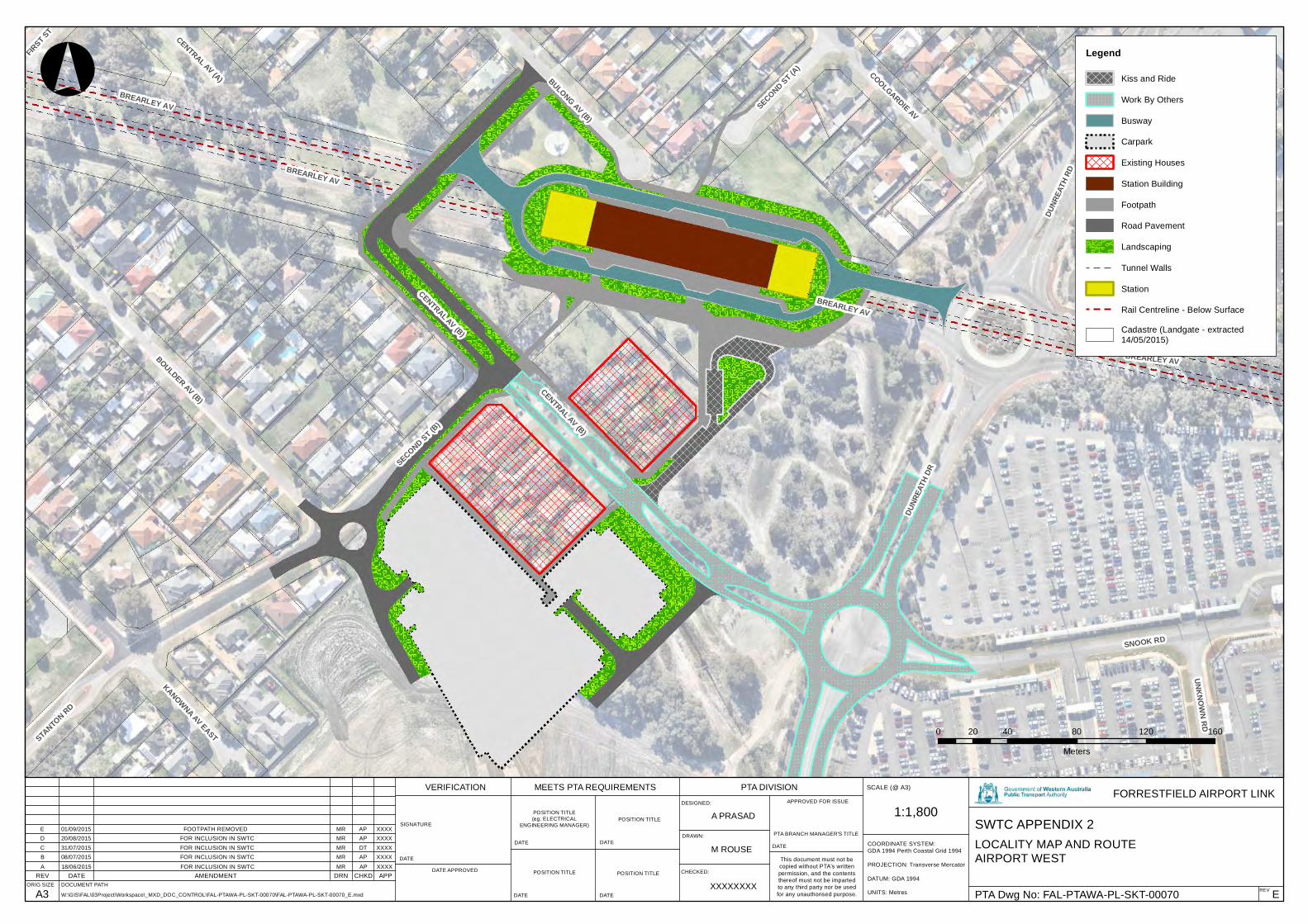
BREARLEY AV
SECOND ST (B)
SNOOK RD
DUNR
EATH
DR
BREARLEY AV BOULDER AV (B)
DUNR
EATH
RD
KANOWNA AV EAST
COOLGARDIE AV
BULONG AV (B)
STANTON RD
CENTRAL AV (B)
SECOND ST (A)
UNKNOWN RD
CENTRAL AV (A)
FIRST ST
BREARLEY AV
BREARLEY AV
CENTRAL AV (B)
62800
62800
2656
00
2656
00
REV DATE AMENDMENT DRN CHKD APPORIG SIZE
A3
FORRESTFIELD AIRPORT LINK
REV EPTA Dwg No: FAL-PTAWA-PL-SKT-00070
SWTC APPENDIX 2
SCALE (@ A3)
1:1,800
COORDINATE SYSTEM:GDA 1994 Perth Coastal Grid 1994
PROJECTION: Transverse Mercator
DATUM: GDA 1994
UNITS: Metres
DESIGNED:
DRAWN:
CHECKED:
APPROVED FOR ISSUE
A PRASAD
M ROUSE
XXXXXXXXW:\GIS\FAL\03Project\Workspace\_MXD_DOC_CONTROL\FAL-PTAWA-PL-SKT-00070\FAL-PTAWA-PL-SKT-00070_E.mxd
DOCUMENT PATH
°
0 40 80 120 16020
Meters
This document must not becopied without PTA's writtenpermission, and the contentsthereof must not be impartedto any third party nor be usedfor any unauthorised purpose.
DATE
PTA BRANCH MANAGER'S TITLE
PTA DIVISIONMEETS PTA REQUIREMENTSVERIFICATION
DATE
DATE
DATE
DATE
DATE
DATE APPROVED
SIGNATURE
POSITION TITLE(eg. ELECTRICAL
ENGINEERING MANAGER)POSITION TITLE
POSITION TITLE POSITION TITLE
Legend
Kiss and Ride
Work By Others
Busway
Carpark
Existing Houses
Station Building
Footpath
Road Pavement
Landscaping
Tunnel Walls
Station
Rail Centreline - Below Surface
Cadastre (Landgate - extracted14/05/2015)
A 18/06/2015 FOR INCLUSION IN SWTC MR AP XXXX
LOCALITY MAP AND ROUTEAIRPORT WESTB 08/07/2015 FOR INCLUSION IN SWTC MR AP XXXX
C 31/07/2015 FOR INCLUSION IN SWTC MR DT XXXXD 20/08/2015 FOR INCLUSION IN SWTC MR AP XXXXE 01/09/2015 FOOTPATH REMOVED MR AP XXXX

KISS ANDRIDE
COOLGARDIE AV
SECOND ST (B)
SNOOK RD
FIRST ST CENTRAL AV (A)
SECOND ST (A)
STANTON RD
UNKNOWN RD
CENTRAL AV (B)
DUNR
EATH
DR
KANOWNA AV EAST
BULONG AV (B) DUNR
EATH
RD
BOULDER AV (B)
° 0 30 60m Drawing No: PTA-GIS-FAL-0040
Map
by:
Date: 18/08/2015Forrestfield - Airport Link Traffic and Transport Analysis
WALKING AND CYCLING
W:\G
IS\F
AL\
03P
roje
ct\W
orks
pace
\_S
KT\
PTA
-GIS
-FA
L-00
40\P
TA-G
IS-F
AL-
0040
_V1.
mxd
Coordinate System: GDA 1994 Perth Coastal Grid 1994Projection: Transverse MercatorDatum: GDA 1994Units: Meter
A3 scale: 1:1,800
Crossing Facility
Pedestrian Access
Shared Footpath
Bike Shelters
Perth Airport Boundary
Kiss and Ride
Busway
Carpark
Station Building
Footpath
Road Pavement
Landscaping
Cadastre (Landgate - extracted14/05/2015)
Legend
Version: 1

KISS ANDRIDE
COOLGARDIE AV
SECOND ST (B)
SNOOK RD
FIRST ST CENTRAL AV (A)
SECOND ST (A)
STANTON RD
UNKNOWN RD
CENTRAL AV (B)
DUNR
EATH
DR
KANOWNA AV EAST
BULONG AV (B) DUNR
EATH
RD
BOULDER AV (B)
° 0 30 60m Drawing No: PTA-GIS-FAL-0041
Map
by:
Date: 18/08/2015Forrestfield - Airport Link Traffic and Transport Analysis
PUBLIC TRANSPORT ACCESS
W:\G
IS\F
AL\
03P
roje
ct\W
orks
pace
\_S
KT\
PTA
-GIS
-FA
L-00
41\P
TA-G
IS-F
AL-
0041
_V1.
mxd
Coordinate System: GDA 1994 Perth Coastal Grid 1994Projection: Transverse MercatorDatum: GDA 1994Units: Meter
A3 scale: 1:1,800
Bus Access
Train Access
Bus Route
Taxi Bay
Perth Airport Boundary
Kiss and Ride
Work By Others
Busway
Carpark
Station Building
Footpath
Road Pavement
Landscaping
Cadastre (Landgate - extracted14/05/2015)
Rail Below Surface
Tunnel Walls
Legend
Version: 1
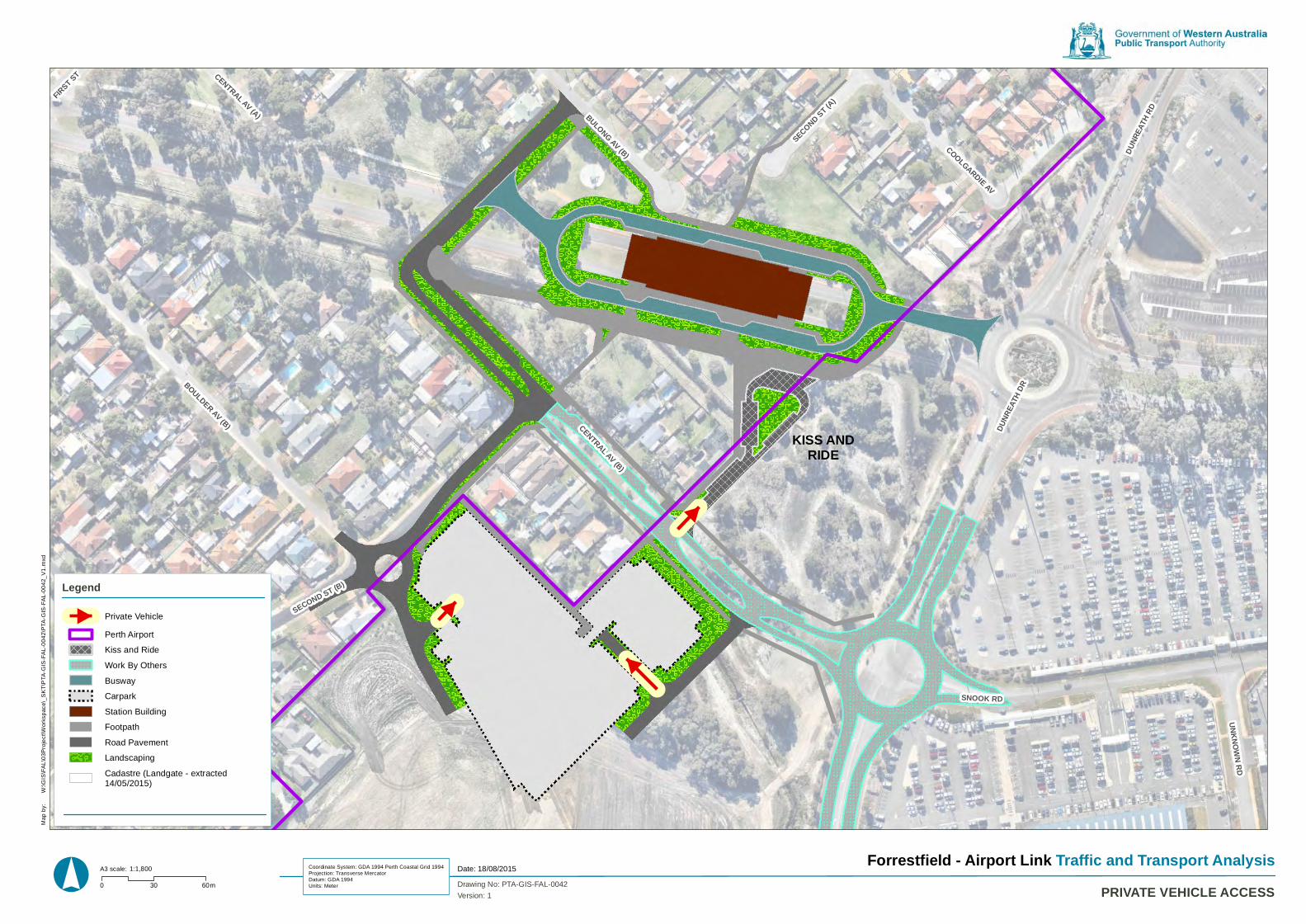
KISS ANDRIDE
COOLGARDIE AV
SECOND ST (B)
SNOOK RD
FIRST ST CENTRAL AV (A)
SECOND ST (A)
STANTON RD
UNKNOWN RD
CENTRAL AV (B)
DUNR
EATH
DR
KANOWNA AV EAST
BULONG AV (B) DUNR
EATH
RD
BOULDER AV (B)
° 0 30 60m Drawing No: PTA-GIS-FAL-0042
Map
by:
Date: 18/08/2015Forrestfield - Airport Link Traffic and Transport Analysis
PRIVATE VEHICLE ACCESS
W:\G
IS\F
AL\
03P
roje
ct\W
orks
pace
\_S
KT\
PTA
-GIS
-FA
L-00
42\P
TA-G
IS-F
AL-
0042
_V1.
mxd
Coordinate System: GDA 1994 Perth Coastal Grid 1994Projection: Transverse MercatorDatum: GDA 1994Units: Meter
A3 scale: 1:1,800
Private Vehicle
Perth Airport
Kiss and Ride
Work By Others
Busway
Carpark
Station Building
Footpath
Road Pavement
Landscaping
Cadastre (Landgate - extracted14/05/2015)
Legend
Version: 1
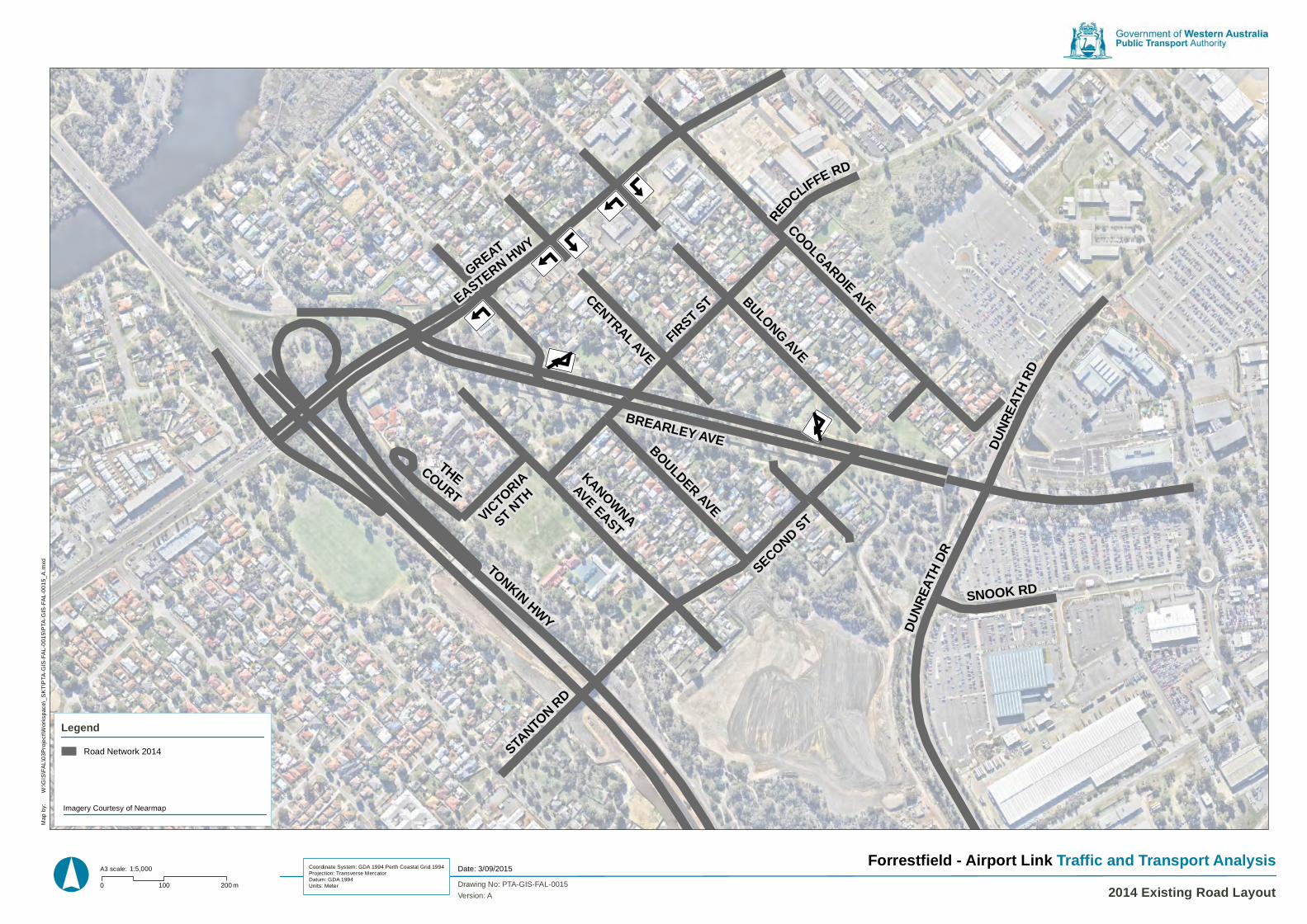
ÝÞßà
ÝÞßà
ÝÞßà
ÝÞßà
ÝÞßà
ÝÞßá
ÝÞßá
SECOND STCOOLGARDIE AVE
KANOWNAAVE EAST
BULONG AVE
THECOURT
FIRST ST
VICTORIA
ST NTH
REDCLIFFE RD
GREAT
EASTERN HWY
DUNR
EATH
DR
CENTRAL AVE
SNOOK RD
BREARLEY AVEBOULDER AVE
DUNR
EATH
RD
STANTON RD
TONKIN HWY
° 0 100 200 m Drawing No: PTA-GIS-FAL-0015
Map
by:
Date: 3/09/2015Forrestfield - Airport Link Traffic and Transport Analysis
2014 Existing Road Layout
W:\G
IS\F
AL\
03P
roje
ct\W
orks
pace
\_S
KT\
PTA
-GIS
-FA
L-00
15\P
TA-G
IS-F
AL-
0015
_A.m
xd
Coordinate System: GDA 1994 Perth Coastal Grid 1994Projection: Transverse MercatorDatum: GDA 1994Units: Meter
A3 scale: 1:5,000
Road Network 2014
Legend
Version: A
Imagery Courtesy of Nearmap
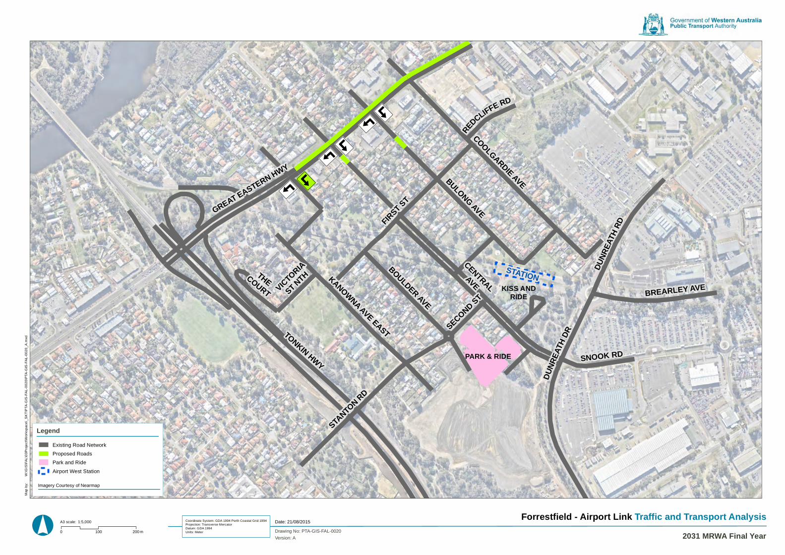
ÝÞßà
ÝÞßà
ÝÞßà
ÝÞßà
ÝÞßà
KISS ANDRIDE
ÝÞßà
STATION
PARK & RIDE
SECOND STCOOLGARDIE AVE
KANOWNA AVE EASTBULONG AVE
THECOURT
GREAT EASTERN HWY
FIRST ST
VICTORIA
ST NTH
REDCLIFFE RD
DUNR
EATH
DR
SNOOK RD
CENTRALAVE
BOULDER AVE
BREARLEY AVE
DUNR
EATH
RD
STANTON RD
TONKIN HWY
° 0 100 200 m Drawing No: PTA-GIS-FAL-0020
Map
by:
Date: 21/08/2015Forrestfield - Airport Link Traffic and Transport Analysis
2031 MRWA Final Year
W:\G
IS\F
AL\
03P
roje
ct\W
orks
pace
\_S
KT\
PTA
-GIS
-FA
L-00
20\P
TA-G
IS-F
AL-
0020
_A.m
xd
Coordinate System: GDA 1994 Perth Coastal Grid 1994Projection: Transverse MercatorDatum: GDA 1994Units: Meter
A3 scale: 1:5,000
Existing Road Network
Proposed Roads
Park and Ride
Airport West Station
Legend
Version: A
Imagery Courtesy of Nearmap
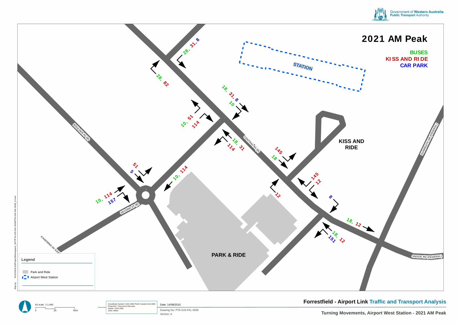
KISS ANDRIDE
28, 31, 8
28, 82 18, 31, 810
10, 51
114
18, 31 14518
14512
114
10, 114
10, 114157
5
51
12
18, 12 151
18, 12
8
BUSESKISS AND RIDE
CAR PARK
2021 AM Peak
SECOND ST (B)
DUNR
EATH
DR(FE
DERA
L)
STANTON RD
KANOWNA AV EAST
SNOOK RD (FEDERAL)
CENTRAL AV (B)
BOULDER AV (B)
STATION
PARK & RIDE
° 0 25 50m Drawing No: PTA-GIS-FAL-0035
Map
by:
Date: 14/08/2015Forrestfield - Airport Link Traffic and Transport Analysis
Turning Movements, Airport West Station - 2021 AM Peak
W:\G
IS\F
AL\
03P
roje
ct\W
orks
pace
\_S
KT\
PTA
-GIS
-FA
L-00
35\P
TA-G
IS-F
AL-
0035
_A.m
xd
Coordinate System: GDA 1994 Perth Coastal Grid 1994Projection: Transverse MercatorDatum: GDA 1994Units: Meter
A3 scale: 1:1,400
Park and Ride
Airport West Station
Legend
Version: A
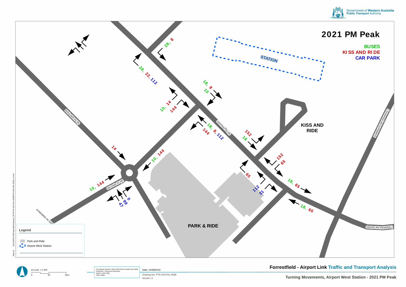
KISS ANDRIDE
28, 8
28, 22, 112 18, 810
10, 14
144
18, 8, 112
15218
15265
144
10, 144
10, 144
99
14
65
18, 65
31
18, 65 11
2
BUSESKISS AND RIDE
CAR PARK
47 0
2021 PM Peak
SECOND ST (B)
DUNR
EATH
DR(FE
DERA
L)
STANTON RD
KANOWNA AV EAST
SNOOK RD (FEDERAL)
CENTRAL AV (B)
BOULDER AV (B)
STATION
PARK & RIDE
° 0 25 50m Drawing No: PTA-GIS-FAL-0036
Map
by:
Date: 14/08/2015Forrestfield - Airport Link Traffic and Transport Analysis
Turning Movements, Airport West Station - 2021 PM Peak
W:\G
IS\F
AL\
03P
roje
ct\W
orks
pace
\_S
KT\
PTA
-GIS
-FA
L-00
36\P
TA-G
IS-F
AL-
0036
_A.m
xd
Coordinate System: GDA 1994 Perth Coastal Grid 1994Projection: Transverse MercatorDatum: GDA 1994Units: Meter
A3 scale: 1:1,400
Park and Ride
Airport West Station
Legend
Version: A
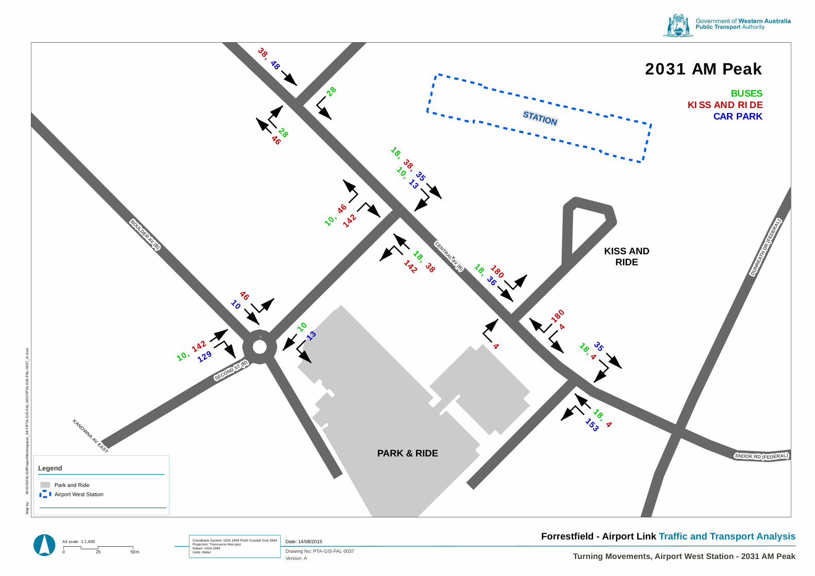
KISS ANDRIDE
28
28
18, 38, 35
10, 13
10, 46
142
18, 38 180
18, 4
1804
142
10, 142
10
4
18, 4
35
BUSESKISS AND RIDE
CAR PARK
2031 AM Peak38, 48
46
46
129 13
18, 36
153
10
SECOND ST (B)
DUNR
EATH
DR(FE
DERA
L)
STANTON RD
KANOWNA AV EAST
SNOOK RD (FEDERAL)
CENTRAL AV (B)
BOULDER AV (B)
STATION
PARK & RIDE
° 0 25 50m Drawing No: PTA-GIS-FAL-0037
Map
by:
Date: 14/08/2015Forrestfield - Airport Link Traffic and Transport Analysis
Turning Movements, Airport West Station - 2031 AM Peak
W:\G
IS\F
AL\
03P
roje
ct\W
orks
pace
\_S
KT\
PTA
-GIS
-FA
L-00
37\P
TA-G
IS-F
AL-
0037
_A.m
xd
Coordinate System: GDA 1994 Perth Coastal Grid 1994Projection: Transverse MercatorDatum: GDA 1994Units: Meter
A3 scale: 1:1,400
Park and Ride
Airport West Station
Legend
Version: A

KISS ANDRIDE
28
28
18, 15
10, 13
10, 13
124
18, 15, 110
139
18, 65
13965
124
10, 124
13
65
18, 65
110
BUSESKISS AND RIDE
CAR PARK
2031 PM Peak15
13, 110
69 6
35
93
10
18
SECOND ST (B)
DUNR
EATH
DR(FE
DERA
L)
STANTON RD
KANOWNA AV EAST
SNOOK RD (FEDERAL)
CENTRAL AV (B)
BOULDER AV (B)
STATION
PARK & RIDE
° 0 25 50m Drawing No: PTA-GIS-FAL-0038
Map
by:
Date: 17/08/2015Forrestfield - Airport Link Traffic and Transport Analysis
Turning Movements, Airport West Station - 2031 PM Peak
W:\G
IS\F
AL\
03P
roje
ct\W
orks
pace
\_S
KT\
PTA
-GIS
-FA
L-00
38\P
TA-G
IS-F
AL-
0038
_A.m
xd
Coordinate System: GDA 1994 Perth Coastal Grid 1994Projection: Transverse MercatorDatum: GDA 1994Units: Meter
A3 scale: 1:1,400
Park and Ride
Airport West Station
Legend
Version: A
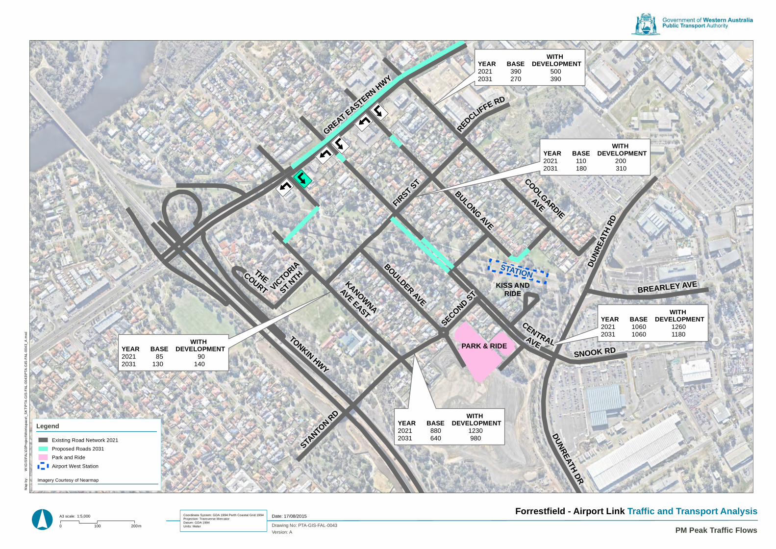
ÝÞßà
ÝÞßà
ÝÞßà
ÝÞßà
ÝÞßà
KISS ANDRIDE
ÝÞßà
WITHYEAR BASE DEVELOPMENT2021 85 902031 130 140
WITHYEAR BASE DEVELOPMENT2021 880 12302031 640 980
WITHYEAR BASE DEVELOPMENT2021 1060 12602031 1060 1180
WITHYEAR BASE DEVELOPMENT2021 110 2002031 180 310
WITHYEAR BASE DEVELOPMENT2021 390 5002031 270 390
STATION
PARK & RIDE
SECOND ST
COOLGARDIEAVE
KANOWNAAVE EAST
BULONG AVETHECOURT
GREAT EASTERN HWY
FIRST ST
VICTORIA
ST NTH
REDCLIFFE RD
DUNREATH DR
SNOOK RD
CENTRALAVE
BOULDER AVE
BREARLEY AVE
DUNR
EATH
RD
STANTON RD
TONKIN HWY
° 0 100 200m Drawing No: PTA-GIS-FAL-0043
Map
by:
Date: 17/08/2015Forrestfield - Airport Link Traffic and Transport Analysis
PM Peak Traffic Flows
W:\G
IS\F
AL\
03P
roje
ct\W
orks
pace
\_S
KT\
PTA
-GIS
-FA
L-00
43\P
TA-G
IS-F
AL-
0043
_A.m
xd
Coordinate System: GDA 1994 Perth Coastal Grid 1994Projection: Transverse MercatorDatum: GDA 1994Units: Meter
A3 scale: 1:5,000
Existing Road Network 2021
Proposed Roads 2031
Park and Ride
Airport West Station
Legend
Version: A
Imagery Courtesy of Nearmap
45 Forrestfield Airport Link: TIA – Airport West Station | 17/09/15
Appendix 2 – Sidra Results
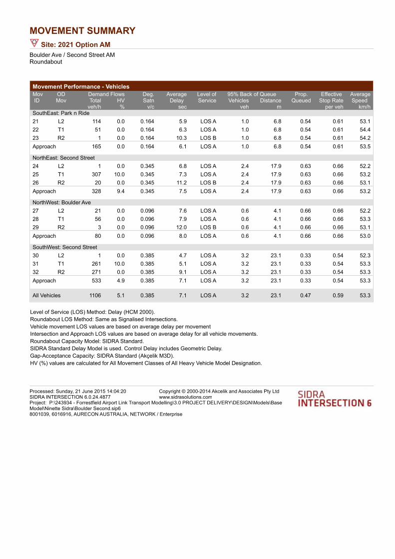
MOVEMENT SUMMARY
Site: 2021 Option AM
Boulder Ave / Second Street AMRoundabout
Movement Performance - Vehicles
Demand Flows 95% Back of QueueMovID
ODMov
Deg.Satn
AverageDelay
Level ofService
Prop. Queued
Effective Stop Rate
AverageSpeed Total HV Vehicles Distance
veh/h % v/c sec veh m per veh km/hSouthEast: Park n Ride
21 L2 114 0.0 0.164 5.9 LOS A 1.0 6.8 0.54 0.61 53.1
22 T1 51 0.0 0.164 6.3 LOS A 1.0 6.8 0.54 0.61 54.4
23 R2 1 0.0 0.164 10.3 LOS B 1.0 6.8 0.54 0.61 54.2
Approach 165 0.0 0.164 6.1 LOS A 1.0 6.8 0.54 0.61 53.5
NorthEast: Second Street
24 L2 1 0.0 0.345 6.8 LOS A 2.4 17.9 0.63 0.66 52.2
25 T1 307 10.0 0.345 7.3 LOS A 2.4 17.9 0.63 0.66 53.2
26 R2 20 0.0 0.345 11.2 LOS B 2.4 17.9 0.63 0.66 53.1
Approach 328 9.4 0.345 7.5 LOS A 2.4 17.9 0.63 0.66 53.2
NorthWest: Boulder Ave
27 L2 21 0.0 0.096 7.6 LOS A 0.6 4.1 0.66 0.66 52.2
28 T1 56 0.0 0.096 7.9 LOS A 0.6 4.1 0.66 0.66 53.3
29 R2 3 0.0 0.096 12.0 LOS B 0.6 4.1 0.66 0.66 53.1
Approach 80 0.0 0.096 8.0 LOS A 0.6 4.1 0.66 0.66 53.0
SouthWest: Second Street
30 L2 1 0.0 0.385 4.7 LOS A 3.2 23.1 0.33 0.54 52.3
31 T1 261 10.0 0.385 5.1 LOS A 3.2 23.1 0.33 0.54 53.3
32 R2 271 0.0 0.385 9.1 LOS A 3.2 23.1 0.33 0.54 53.3
Approach 533 4.9 0.385 7.1 LOS A 3.2 23.1 0.33 0.54 53.3
All Vehicles 1106 5.1 0.385 7.1 LOS A 3.2 23.1 0.47 0.59 53.3
Level of Service (LOS) Method: Delay (HCM 2000).
Roundabout LOS Method: Same as Signalised Intersections.
Vehicle movement LOS values are based on average delay per movement
Intersection and Approach LOS values are based on average delay for all vehicle movements.
Roundabout Capacity Model: SIDRA Standard.
SIDRA Standard Delay Model is used. Control Delay includes Geometric Delay.
Gap-Acceptance Capacity: SIDRA Standard (Akçelik M3D).
HV (%) values are calculated for All Movement Classes of All Heavy Vehicle Model Designation.
Processed: Sunday, 21 June 2015 14:04:20SIDRA INTERSECTION 6.0.24.4877
Copyright © 2000-2014 Akcelik and Associates Pty Ltdwww.sidrasolutions.com
Project: P:\243934 - Forrestfield Airport Link Transport Modelling\3.0 PROJECT DELIVERY\DESIGN\Models\Base Model\Ninette Sidra\Boulder Second.sip68001039, 6016916, AURECON AUSTRALIA, NETWORK / Enterprise
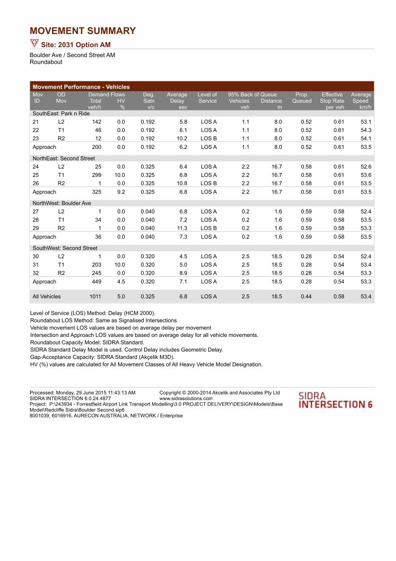
MOVEMENT SUMMARY
Site: 2031 Option AM
Boulder Ave / Second Street AMRoundabout
Movement Performance - Vehicles
Demand Flows 95% Back of QueueMovID
ODMov
Deg.Satn
AverageDelay
Level ofService
Prop. Queued
Effective Stop Rate
AverageSpeed Total HV Vehicles Distance
veh/h % v/c sec veh m per veh km/hSouthEast: Park n Ride
21 L2 142 0.0 0.192 5.8 LOS A 1.1 8.0 0.52 0.61 53.1
22 T1 46 0.0 0.192 6.1 LOS A 1.1 8.0 0.52 0.61 54.3
23 R2 12 0.0 0.192 10.2 LOS B 1.1 8.0 0.52 0.61 54.1
Approach 200 0.0 0.192 6.2 LOS A 1.1 8.0 0.52 0.61 53.5
NorthEast: Second Street
24 L2 25 0.0 0.325 6.4 LOS A 2.2 16.7 0.58 0.61 52.6
25 T1 299 10.0 0.325 6.8 LOS A 2.2 16.7 0.58 0.61 53.6
26 R2 1 0.0 0.325 10.8 LOS B 2.2 16.7 0.58 0.61 53.5
Approach 325 9.2 0.325 6.8 LOS A 2.2 16.7 0.58 0.61 53.5
NorthWest: Boulder Ave
27 L2 1 0.0 0.040 6.8 LOS A 0.2 1.6 0.59 0.58 52.4
28 T1 34 0.0 0.040 7.2 LOS A 0.2 1.6 0.59 0.58 53.5
29 R2 1 0.0 0.040 11.3 LOS B 0.2 1.6 0.59 0.58 53.3
Approach 36 0.0 0.040 7.3 LOS A 0.2 1.6 0.59 0.58 53.5
SouthWest: Second Street
30 L2 1 0.0 0.320 4.5 LOS A 2.5 18.5 0.28 0.54 52.4
31 T1 203 10.0 0.320 5.0 LOS A 2.5 18.5 0.28 0.54 53.4
32 R2 245 0.0 0.320 8.9 LOS A 2.5 18.5 0.28 0.54 53.3
Approach 449 4.5 0.320 7.1 LOS A 2.5 18.5 0.28 0.54 53.3
All Vehicles 1011 5.0 0.325 6.8 LOS A 2.5 18.5 0.44 0.58 53.4
Level of Service (LOS) Method: Delay (HCM 2000).
Roundabout LOS Method: Same as Signalised Intersections.
Vehicle movement LOS values are based on average delay per movement
Intersection and Approach LOS values are based on average delay for all vehicle movements.
Roundabout Capacity Model: SIDRA Standard.
SIDRA Standard Delay Model is used. Control Delay includes Geometric Delay.
Gap-Acceptance Capacity: SIDRA Standard (Akçelik M3D).
HV (%) values are calculated for All Movement Classes of All Heavy Vehicle Model Designation.
Processed: Monday, 29 June 2015 11:43:13 AMSIDRA INTERSECTION 6.0.24.4877
Copyright © 2000-2014 Akcelik and Associates Pty Ltdwww.sidrasolutions.com
Project: P:\243934 - Forrestfield Airport Link Transport Modelling\3.0 PROJECT DELIVERY\DESIGN\Models\Base Model\Redcliffe Sidra\Boulder Second.sip68001039, 6016916, AURECON AUSTRALIA, NETWORK / Enterprise

MOVEMENT SUMMARY
Site: 2021 Option PM
Boulder Ave / Second Street AMRoundabout
Movement Performance - Vehicles
Demand Flows 95% Back of QueueMovID
ODMov
Deg.Satn
AverageDelay
Level ofService
Prop. Queued
Effective Stop Rate
AverageSpeed Total HV Vehicles Distance
veh/h % v/c sec veh m per veh km/hSouthEast: Park n Ride
21 L2 191 0.0 0.350 7.4 LOS A 2.3 16.4 0.71 0.75 52.3
22 T1 113 0.0 0.350 7.7 LOS A 2.3 16.4 0.71 0.75 53.5
23 R2 5 0.0 0.350 11.8 LOS B 2.3 16.4 0.71 0.75 53.3
Approach 308 0.0 0.350 7.6 LOS A 2.3 16.4 0.71 0.75 52.8
NorthEast: Second Street
24 L2 8 0.0 0.426 5.5 LOS A 3.6 26.7 0.53 0.56 52.4
25 T1 404 10.0 0.426 5.9 LOS A 3.6 26.7 0.53 0.56 53.4
26 R2 88 0.0 0.426 9.9 LOS A 3.6 26.7 0.53 0.56 53.3
Approach 501 8.1 0.426 6.6 LOS A 3.6 26.7 0.53 0.56 53.4
NorthWest: Boulder Ave
27 L2 8 0.0 0.031 7.8 LOS A 0.2 1.4 0.71 0.63 52.0
28 T1 14 0.0 0.031 8.1 LOS A 0.2 1.4 0.71 0.63 53.1
29 R2 1 0.0 0.031 12.2 LOS B 0.2 1.4 0.71 0.63 52.9
Approach 23 0.0 0.031 8.2 LOS A 0.2 1.4 0.71 0.63 52.7
SouthWest: Second Street
30 L2 1 0.0 0.509 6.1 LOS A 4.4 32.9 0.62 0.62 51.9
31 T1 428 10.0 0.509 6.5 LOS A 4.4 32.9 0.62 0.62 52.9
32 R2 144 0.0 0.509 10.5 LOS B 4.4 32.9 0.62 0.62 52.8
Approach 574 7.5 0.509 7.5 LOS A 4.4 32.9 0.62 0.62 52.8
All Vehicles 1406 5.9 0.509 7.2 LOS A 4.4 32.9 0.61 0.63 53.0
Level of Service (LOS) Method: Delay (HCM 2000).
Roundabout LOS Method: Same as Signalised Intersections.
Vehicle movement LOS values are based on average delay per movement
Intersection and Approach LOS values are based on average delay for all vehicle movements.
Roundabout Capacity Model: SIDRA Standard.
SIDRA Standard Delay Model is used. Control Delay includes Geometric Delay.
Gap-Acceptance Capacity: SIDRA Standard (Akçelik M3D).
HV (%) values are calculated for All Movement Classes of All Heavy Vehicle Model Designation.
Processed: Sunday, 21 June 2015 14:04:23SIDRA INTERSECTION 6.0.24.4877
Copyright © 2000-2014 Akcelik and Associates Pty Ltdwww.sidrasolutions.com
Project: P:\243934 - Forrestfield Airport Link Transport Modelling\3.0 PROJECT DELIVERY\DESIGN\Models\Base Model\Ninette Sidra\Boulder Second.sip68001039, 6016916, AURECON AUSTRALIA, NETWORK / Enterprise
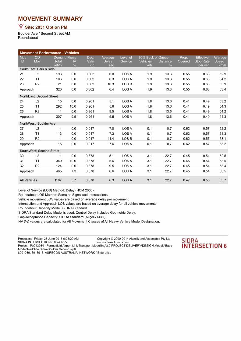
MOVEMENT SUMMARY
Site: 2031 Option PM
Boulder Ave / Second Street AMRoundabout
Movement Performance - Vehicles
Demand Flows 95% Back of QueueMovID
ODMov
Deg.Satn
AverageDelay
Level ofService
Prop. Queued
Effective Stop Rate
AverageSpeed Total HV Vehicles Distance
veh/h % v/c sec veh m per veh km/hSouthEast: Park n Ride
21 L2 193 0.0 0.302 6.0 LOS A 1.9 13.3 0.55 0.63 52.9
22 T1 106 0.0 0.302 6.3 LOS A 1.9 13.3 0.55 0.63 54.2
23 R2 21 0.0 0.302 10.3 LOS B 1.9 13.3 0.55 0.63 53.9
Approach 320 0.0 0.302 6.4 LOS A 1.9 13.3 0.55 0.63 53.4
NorthEast: Second Street
24 L2 15 0.0 0.261 5.1 LOS A 1.8 13.6 0.41 0.49 53.2
25 T1 292 10.0 0.261 5.6 LOS A 1.8 13.6 0.41 0.49 54.3
26 R2 1 0.0 0.261 9.5 LOS A 1.8 13.6 0.41 0.49 54.2
Approach 307 9.5 0.261 5.6 LOS A 1.8 13.6 0.41 0.49 54.3
NorthWest: Boulder Ave
27 L2 1 0.0 0.017 7.0 LOS A 0.1 0.7 0.62 0.57 52.2
28 T1 13 0.0 0.017 7.3 LOS A 0.1 0.7 0.62 0.57 53.3
29 R2 1 0.0 0.017 11.4 LOS B 0.1 0.7 0.62 0.57 53.1
Approach 15 0.0 0.017 7.6 LOS A 0.1 0.7 0.62 0.57 53.2
SouthWest: Second Street
30 L2 1 0.0 0.378 5.1 LOS A 3.1 22.7 0.45 0.54 52.5
31 T1 340 10.0 0.378 5.6 LOS A 3.1 22.7 0.45 0.54 53.5
32 R2 124 0.0 0.378 9.5 LOS A 3.1 22.7 0.45 0.54 53.4
Approach 465 7.3 0.378 6.6 LOS A 3.1 22.7 0.45 0.54 53.5
All Vehicles 1107 5.7 0.378 6.3 LOS A 3.1 22.7 0.47 0.55 53.7
Level of Service (LOS) Method: Delay (HCM 2000).
Roundabout LOS Method: Same as Signalised Intersections.
Vehicle movement LOS values are based on average delay per movement
Intersection and Approach LOS values are based on average delay for all vehicle movements.
Roundabout Capacity Model: SIDRA Standard.
SIDRA Standard Delay Model is used. Control Delay includes Geometric Delay.
Gap-Acceptance Capacity: SIDRA Standard (Akçelik M3D).
HV (%) values are calculated for All Movement Classes of All Heavy Vehicle Model Designation.
Processed: Friday, 26 June 2015 9:25:20 AMSIDRA INTERSECTION 6.0.24.4877
Copyright © 2000-2014 Akcelik and Associates Pty Ltdwww.sidrasolutions.com
Project: P:\243934 - Forrestfield Airport Link Transport Modelling\3.0 PROJECT DELIVERY\DESIGN\Models\Base Model\Redcliffe Sidra\Boulder Second.sip68001039, 6016916, AURECON AUSTRALIA, NETWORK / Enterprise
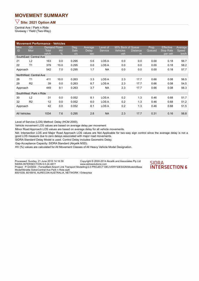
MOVEMENT SUMMARY
Site: 2021 Option AM
Central Ave / Park n RideGiveway / Yield (Two-Way)
Movement Performance - Vehicles
Demand Flows 95% Back of QueueMovID
ODMov
Deg.Satn
AverageDelay
Level ofService
Prop. Queued
Effective Stop Rate
AverageSpeed Total HV Vehicles Distance
veh/h % v/c sec veh m per veh km/hSouthEast: Central Ave
21 L2 163 0.0 0.295 5.6 LOS A 0.0 0.0 0.00 0.18 56.7
22 T1 379 10.0 0.295 0.0 LOS A 0.0 0.0 0.00 0.18 58.2
Approach 542 7.0 0.295 1.7 NA 0.0 0.0 0.00 0.18 57.7
NorthWest: Central Ave
28 T1 411 10.0 0.263 3.3 LOS A 2.3 17.7 0.66 0.08 56.5
29 R2 39 0.0 0.263 8.7 LOS A 2.3 17.7 0.66 0.08 54.5
Approach 449 9.1 0.263 3.7 NA 2.3 17.7 0.66 0.08 56.3
SouthWest: Park n Ride
30 L2 31 0.0 0.052 8.1 LOS A 0.2 1.3 0.46 0.68 51.7
32 R2 12 0.0 0.052 8.0 LOS A 0.2 1.3 0.46 0.68 51.2
Approach 42 0.0 0.052 8.1 LOS A 0.2 1.3 0.46 0.68 51.5
All Vehicles 1034 7.6 0.295 2.8 NA 2.3 17.7 0.31 0.16 56.8
Level of Service (LOS) Method: Delay (HCM 2000).
Vehicle movement LOS values are based on average delay per movement
Minor Road Approach LOS values are based on average delay for all vehicle movements.
NA: Intersection LOS and Major Road Approach LOS values are Not Applicable for two-way sign control since the average delay is not a good LOS measure due to zero delays associated with major road movements.
SIDRA Standard Delay Model is used. Control Delay includes Geometric Delay.
Gap-Acceptance Capacity: SIDRA Standard (Akçelik M3D).
HV (%) values are calculated for All Movement Classes of All Heavy Vehicle Model Designation.
Processed: Sunday, 21 June 2015 14:16:30SIDRA INTERSECTION 6.0.24.4877
Copyright © 2000-2014 Akcelik and Associates Pty Ltdwww.sidrasolutions.com
Project: P:\243934 - Forrestfield Airport Link Transport Modelling\3.0 PROJECT DELIVERY\DESIGN\Models\Base Model\Ninette Sidra\Central Ave Park n Ride.sip68001039, 6016916, AURECON AUSTRALIA, NETWORK / Enterprise

MOVEMENT SUMMARY
Site: 2031 Option AM
Central Ave / Park n RideGiveway / Yield (Two-Way)
Movement Performance - Vehicles
Demand Flows 95% Back of QueueMovID
ODMov
Deg.Satn
AverageDelay
Level ofService
Prop. Queued
Effective Stop Rate
AverageSpeed Total HV Vehicles Distance
veh/h % v/c sec veh m per veh km/hSouthEast: Central Ave
21 L2 157 0.0 0.311 5.6 LOS A 0.0 0.0 0.00 0.16 56.8
22 T1 415 10.0 0.311 0.0 LOS A 0.0 0.0 0.00 0.16 58.4
Approach 572 7.3 0.311 1.6 NA 0.0 0.0 0.00 0.16 57.9
NorthWest: Central Ave
28 T1 347 10.0 0.253 3.5 LOS A 2.2 16.3 0.67 0.14 56.0
29 R2 61 0.0 0.253 8.9 LOS A 2.2 16.3 0.67 0.14 54.0
Approach 408 8.5 0.253 4.3 NA 2.2 16.3 0.67 0.14 55.7
SouthWest: Park n Ride
30 L2 26 0.0 0.033 7.7 LOS A 0.1 0.8 0.46 0.65 52.0
32 R2 4 0.0 0.033 7.6 LOS A 0.1 0.8 0.46 0.65 51.5
Approach 31 0.0 0.033 7.6 LOS A 0.1 0.8 0.46 0.65 52.0
All Vehicles 1011 7.5 0.311 2.8 NA 2.2 16.3 0.29 0.17 56.8
Level of Service (LOS) Method: Delay (HCM 2000).
Vehicle movement LOS values are based on average delay per movement
Minor Road Approach LOS values are based on average delay for all vehicle movements.
NA: Intersection LOS and Major Road Approach LOS values are Not Applicable for two-way sign control since the average delay is not a good LOS measure due to zero delays associated with major road movements.
SIDRA Standard Delay Model is used. Control Delay includes Geometric Delay.
Gap-Acceptance Capacity: SIDRA Standard (Akçelik M3D).
HV (%) values are calculated for All Movement Classes of All Heavy Vehicle Model Designation.
Processed: Monday, 29 June 2015 11:48:41 AMSIDRA INTERSECTION 6.0.24.4877
Copyright © 2000-2014 Akcelik and Associates Pty Ltdwww.sidrasolutions.com
Project: P:\243934 - Forrestfield Airport Link Transport Modelling\3.0 PROJECT DELIVERY\DESIGN\Models\Base Model\Redcliffe Sidra\Central Ave Park n Ride.sip68001039, 6016916, AURECON AUSTRALIA, NETWORK / Enterprise

MOVEMENT SUMMARY
Site: 2021 Option PM
Central Ave / Park n RideGiveway / Yield (Two-Way)
Movement Performance - Vehicles
Demand Flows 95% Back of QueueMovID
ODMov
Deg.Satn
AverageDelay
Level ofService
Prop. Queued
Effective Stop Rate
AverageSpeed Total HV Vehicles Distance
veh/h % v/c sec veh m per veh km/hSouthEast: Central Ave
21 L2 65 0.0 0.296 5.6 LOS A 0.0 0.0 0.00 0.07 57.6
22 T1 478 10.0 0.296 0.0 LOS A 0.0 0.0 0.00 0.07 59.2
Approach 543 8.8 0.296 0.7 NA 0.0 0.0 0.00 0.07 59.0
NorthWest: Central Ave
28 T1 480 10.0 0.263 3.3 LOS A 2.5 19.2 0.66 0.00 56.9
29 R2 1 0.0 0.263 8.8 LOS A 2.5 19.2 0.66 0.00 54.8
Approach 481 10.0 0.263 3.3 NA 2.5 19.2 0.66 0.00 56.9
SouthWest: Park n Ride
30 L2 113 0.0 0.345 11.3 LOS B 1.5 10.3 0.62 0.88 49.5
32 R2 96 0.0 0.345 11.2 LOS B 1.5 10.3 0.62 0.88 49.0
Approach 208 0.0 0.345 11.3 LOS B 1.5 10.3 0.62 0.88 49.2
All Vehicles 1233 7.8 0.345 3.5 NA 2.5 19.2 0.36 0.18 56.3
Level of Service (LOS) Method: Delay (HCM 2000).
Vehicle movement LOS values are based on average delay per movement
Minor Road Approach LOS values are based on average delay for all vehicle movements.
NA: Intersection LOS and Major Road Approach LOS values are Not Applicable for two-way sign control since the average delay is not a good LOS measure due to zero delays associated with major road movements.
SIDRA Standard Delay Model is used. Control Delay includes Geometric Delay.
Gap-Acceptance Capacity: SIDRA Standard (Akçelik M3D).
HV (%) values are calculated for All Movement Classes of All Heavy Vehicle Model Designation.
Processed: Sunday, 21 June 2015 14:16:33SIDRA INTERSECTION 6.0.24.4877
Copyright © 2000-2014 Akcelik and Associates Pty Ltdwww.sidrasolutions.com
Project: P:\243934 - Forrestfield Airport Link Transport Modelling\3.0 PROJECT DELIVERY\DESIGN\Models\Base Model\Ninette Sidra\Central Ave Park n Ride.sip68001039, 6016916, AURECON AUSTRALIA, NETWORK / Enterprise
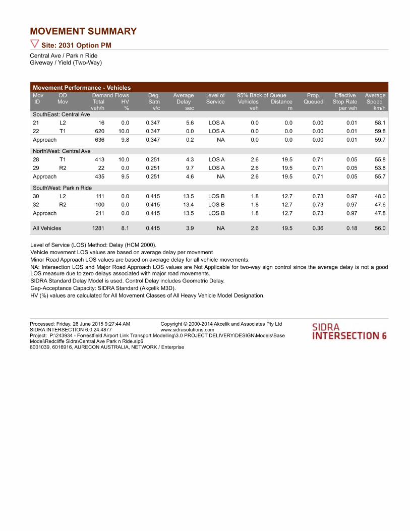
MOVEMENT SUMMARY
Site: 2031 Option PM
Central Ave / Park n RideGiveway / Yield (Two-Way)
Movement Performance - Vehicles
Demand Flows 95% Back of QueueMovID
ODMov
Deg.Satn
AverageDelay
Level ofService
Prop. Queued
Effective Stop Rate
AverageSpeed Total HV Vehicles Distance
veh/h % v/c sec veh m per veh km/hSouthEast: Central Ave
21 L2 16 0.0 0.347 5.6 LOS A 0.0 0.0 0.00 0.01 58.1
22 T1 620 10.0 0.347 0.0 LOS A 0.0 0.0 0.00 0.01 59.8
Approach 636 9.8 0.347 0.2 NA 0.0 0.0 0.00 0.01 59.7
NorthWest: Central Ave
28 T1 413 10.0 0.251 4.3 LOS A 2.6 19.5 0.71 0.05 55.8
29 R2 22 0.0 0.251 9.7 LOS A 2.6 19.5 0.71 0.05 53.8
Approach 435 9.5 0.251 4.6 NA 2.6 19.5 0.71 0.05 55.7
SouthWest: Park n Ride
30 L2 111 0.0 0.415 13.5 LOS B 1.8 12.7 0.73 0.97 48.0
32 R2 100 0.0 0.415 13.4 LOS B 1.8 12.7 0.73 0.97 47.6
Approach 211 0.0 0.415 13.5 LOS B 1.8 12.7 0.73 0.97 47.8
All Vehicles 1281 8.1 0.415 3.9 NA 2.6 19.5 0.36 0.18 56.0
Level of Service (LOS) Method: Delay (HCM 2000).
Vehicle movement LOS values are based on average delay per movement
Minor Road Approach LOS values are based on average delay for all vehicle movements.
NA: Intersection LOS and Major Road Approach LOS values are Not Applicable for two-way sign control since the average delay is not a good LOS measure due to zero delays associated with major road movements.
SIDRA Standard Delay Model is used. Control Delay includes Geometric Delay.
Gap-Acceptance Capacity: SIDRA Standard (Akçelik M3D).
HV (%) values are calculated for All Movement Classes of All Heavy Vehicle Model Designation.
Processed: Friday, 26 June 2015 9:27:44 AMSIDRA INTERSECTION 6.0.24.4877
Copyright © 2000-2014 Akcelik and Associates Pty Ltdwww.sidrasolutions.com
Project: P:\243934 - Forrestfield Airport Link Transport Modelling\3.0 PROJECT DELIVERY\DESIGN\Models\Base Model\Redcliffe Sidra\Central Ave Park n Ride.sip68001039, 6016916, AURECON AUSTRALIA, NETWORK / Enterprise

MOVEMENT SUMMARY
Site: 2021 Option AM
Central Ave / Second StreetGiveway / Yield (Two-Way)
Movement Performance - Vehicles
Demand Flows 95% Back of QueueMovID
ODMov
Deg.Satn
AverageDelay
Level ofService
Prop. Queued
Effective Stop Rate
AverageSpeed Total HV Vehicles Distance
veh/h % v/c sec veh m per veh km/hSouthEast: Central Ave
21 L2 315 10.0 0.234 5.7 LOS A 0.0 0.0 0.00 0.44 54.4
22 T1 97 10.0 0.234 0.0 LOS A 0.0 0.0 0.00 0.44 56.0
Approach 412 10.0 0.234 4.3 NA 0.0 0.0 0.00 0.44 54.8
NorthWest: Central Ave
28 T1 177 10.0 0.110 2.0 LOS A 0.8 6.0 0.51 0.05 57.5
29 R2 15 10.0 0.110 7.5 LOS A 0.8 6.0 0.51 0.05 55.1
Approach 192 10.0 0.110 2.4 NA 0.8 6.0 0.51 0.05 57.3
SouthWest: Second Street
30 L2 9 10.0 0.361 8.9 LOS A 1.7 12.7 0.49 0.82 51.0
32 R2 275 10.0 0.361 8.8 LOS A 1.7 12.7 0.49 0.82 50.5
Approach 284 10.0 0.361 8.8 LOS A 1.7 12.7 0.49 0.82 50.6
All Vehicles 887 10.0 0.361 5.3 NA 1.7 12.7 0.27 0.48 53.8
Level of Service (LOS) Method: Delay (HCM 2000).
Vehicle movement LOS values are based on average delay per movement
Minor Road Approach LOS values are based on average delay for all vehicle movements.
NA: Intersection LOS and Major Road Approach LOS values are Not Applicable for two-way sign control since the average delay is not a good LOS measure due to zero delays associated with major road movements.
SIDRA Standard Delay Model is used. Control Delay includes Geometric Delay.
Gap-Acceptance Capacity: SIDRA Standard (Akçelik M3D).
HV (%) values are calculated for All Movement Classes of All Heavy Vehicle Model Designation.
Processed: Sunday, 21 June 2015 14:19:52SIDRA INTERSECTION 6.0.24.4877
Copyright © 2000-2014 Akcelik and Associates Pty Ltdwww.sidrasolutions.com
Project: P:\243934 - Forrestfield Airport Link Transport Modelling\3.0 PROJECT DELIVERY\DESIGN\Models\Base Model\Ninette Sidra\Central Ave Second Str.sip68001039, 6016916, AURECON AUSTRALIA, NETWORK / Enterprise

MOVEMENT SUMMARY
Site: 2031 Option AM
Central Ave / Second StreetGiveway / Yield (Two-Way)
Movement Performance - Vehicles
Demand Flows 95% Back of QueueMovID
ODMov
Deg.Satn
AverageDelay
Level ofService
Prop. Queued
Effective Stop Rate
AverageSpeed Total HV Vehicles Distance
veh/h % v/c sec veh m per veh km/hSouthEast: Central Ave
21 L2 292 10.0 0.254 5.7 LOS A 0.0 0.0 0.00 0.38 54.9
22 T1 157 10.0 0.254 0.0 LOS A 0.0 0.0 0.00 0.38 56.6
Approach 448 10.0 0.254 3.7 NA 0.0 0.0 0.00 0.38 55.5
NorthWest: Central Ave
28 T1 218 10.0 0.153 2.4 LOS A 1.1 8.6 0.55 0.10 57.0
29 R2 35 10.0 0.153 7.9 LOS A 1.1 8.6 0.55 0.10 54.7
Approach 253 10.0 0.153 3.1 NA 1.1 8.6 0.55 0.10 56.6
SouthWest: Second Street
30 L2 19 10.0 0.309 9.4 LOS A 1.3 9.8 0.51 0.81 50.7
32 R2 201 10.0 0.309 9.3 LOS A 1.3 9.8 0.51 0.81 50.2
Approach 220 10.0 0.309 9.3 LOS A 1.3 9.8 0.51 0.81 50.2
All Vehicles 921 10.0 0.309 4.9 NA 1.3 9.8 0.27 0.41 54.4
Level of Service (LOS) Method: Delay (HCM 2000).
Vehicle movement LOS values are based on average delay per movement
Minor Road Approach LOS values are based on average delay for all vehicle movements.
NA: Intersection LOS and Major Road Approach LOS values are Not Applicable for two-way sign control since the average delay is not a good LOS measure due to zero delays associated with major road movements.
SIDRA Standard Delay Model is used. Control Delay includes Geometric Delay.
Gap-Acceptance Capacity: SIDRA Standard (Akçelik M3D).
HV (%) values are calculated for All Movement Classes of All Heavy Vehicle Model Designation.
Processed: Monday, 29 June 2015 11:51:30 AMSIDRA INTERSECTION 6.0.24.4877
Copyright © 2000-2014 Akcelik and Associates Pty Ltdwww.sidrasolutions.com
Project: P:\243934 - Forrestfield Airport Link Transport Modelling\3.0 PROJECT DELIVERY\DESIGN\Models\Base Model\Redcliffe Sidra\Central Ave Second Str.sip68001039, 6016916, AURECON AUSTRALIA, NETWORK / Enterprise

MOVEMENT SUMMARY
Site: 2021 Option PM
Central Ave / Second StreetGiveway / Yield (Two-Way)
Movement Performance - Vehicles
Demand Flows 95% Back of QueueMovID
ODMov
Deg.Satn
AverageDelay
Level ofService
Prop. Queued
Effective Stop Rate
AverageSpeed Total HV Vehicles Distance
veh/h % v/c sec veh m per veh km/hSouthEast: Central Ave
21 L2 484 10.0 0.391 5.7 LOS A 0.0 0.0 0.00 0.41 54.6
22 T1 205 10.0 0.391 0.1 LOS A 0.0 0.0 0.00 0.41 56.3
Approach 689 10.0 0.391 4.0 NA 0.0 0.0 0.00 0.41 55.1
NorthWest: Central Ave
28 T1 52 10.0 0.055 4.2 LOS A 0.4 2.9 0.62 0.21 54.9
29 R2 19 10.0 0.055 9.7 LOS A 0.4 2.9 0.62 0.21 52.8
Approach 71 10.0 0.055 5.7 NA 0.4 2.9 0.62 0.21 54.3
SouthWest: Second Street
30 L2 13 10.0 0.630 12.2 LOS B 4.4 33.8 0.66 1.04 48.7
32 R2 432 10.0 0.630 12.1 LOS B 4.4 33.8 0.66 1.04 48.3
Approach 444 10.0 0.630 12.1 LOS B 4.4 33.8 0.66 1.04 48.3
All Vehicles 1204 10.0 0.630 7.1 NA 4.4 33.8 0.28 0.63 52.4
Level of Service (LOS) Method: Delay (HCM 2000).
Vehicle movement LOS values are based on average delay per movement
Minor Road Approach LOS values are based on average delay for all vehicle movements.
NA: Intersection LOS and Major Road Approach LOS values are Not Applicable for two-way sign control since the average delay is not a good LOS measure due to zero delays associated with major road movements.
SIDRA Standard Delay Model is used. Control Delay includes Geometric Delay.
Gap-Acceptance Capacity: SIDRA Standard (Akçelik M3D).
HV (%) values are calculated for All Movement Classes of All Heavy Vehicle Model Designation.
Processed: Sunday, 21 June 2015 14:19:54SIDRA INTERSECTION 6.0.24.4877
Copyright © 2000-2014 Akcelik and Associates Pty Ltdwww.sidrasolutions.com
Project: P:\243934 - Forrestfield Airport Link Transport Modelling\3.0 PROJECT DELIVERY\DESIGN\Models\Base Model\Ninette Sidra\Central Ave Second Str.sip68001039, 6016916, AURECON AUSTRALIA, NETWORK / Enterprise

MOVEMENT SUMMARY
Site: 2031 Option PM
Central Ave / Second StreetGiveway / Yield (Two-Way)
Movement Performance - Vehicles
Demand Flows 95% Back of QueueMovID
ODMov
Deg.Satn
AverageDelay
Level ofService
Prop. Queued
Effective Stop Rate
AverageSpeed Total HV Vehicles Distance
veh/h % v/c sec veh m per veh km/hSouthEast: Central Ave
21 L2 284 10.0 0.409 5.7 LOS A 0.0 0.0 0.00 0.23 56.1
22 T1 449 10.0 0.409 0.1 LOS A 0.0 0.0 0.00 0.23 57.8
Approach 734 10.0 0.409 2.2 NA 0.0 0.0 0.00 0.23 57.2
NorthWest: Central Ave
28 T1 114 10.0 0.099 5.0 LOS A 0.8 6.4 0.68 0.15 54.6
29 R2 24 10.0 0.099 10.6 LOS B 0.8 6.4 0.68 0.15 52.5
Approach 138 10.0 0.099 6.0 NA 0.8 6.4 0.68 0.15 54.2
SouthWest: Second Street
30 L2 28 10.0 0.674 16.0 LOS C 4.3 32.7 0.79 1.15 46.4
32 R2 333 10.0 0.674 15.9 LOS C 4.3 32.7 0.79 1.15 46.0
Approach 361 10.0 0.674 15.9 LOS C 4.3 32.7 0.79 1.15 46.0
All Vehicles 1233 10.0 0.674 6.7 NA 4.3 32.7 0.31 0.49 53.1
Level of Service (LOS) Method: Delay (HCM 2000).
Vehicle movement LOS values are based on average delay per movement
Minor Road Approach LOS values are based on average delay for all vehicle movements.
NA: Intersection LOS and Major Road Approach LOS values are Not Applicable for two-way sign control since the average delay is not a good LOS measure due to zero delays associated with major road movements.
SIDRA Standard Delay Model is used. Control Delay includes Geometric Delay.
Gap-Acceptance Capacity: SIDRA Standard (Akçelik M3D).
HV (%) values are calculated for All Movement Classes of All Heavy Vehicle Model Designation.
Processed: Friday, 26 June 2015 9:28:37 AMSIDRA INTERSECTION 6.0.24.4877
Copyright © 2000-2014 Akcelik and Associates Pty Ltdwww.sidrasolutions.com
Project: P:\243934 - Forrestfield Airport Link Transport Modelling\3.0 PROJECT DELIVERY\DESIGN\Models\Base Model\Redcliffe Sidra\Central Ave Second Str.sip68001039, 6016916, AURECON AUSTRALIA, NETWORK / Enterprise
Belmont Station Development Application Report 58
Appendix 3: Public Transport Authority Accessibility Policy

COMPLIANCE WITH THIS DOCUMENT IS MANDATORY 9002-000-043 Rev1.01
Page 1 of 13
ACCESSIBILITY POLICY
1. POLICY
1.1. The Public Transport Authority (PTA) shall as far as reasonably practical provide Public Passenger Transport Services and Facilities that are accessible to all passengers.
1.2. In accordance with the Disability Services Act 1993, the PTA shall maintain a publicly available Disability Access and Inclusion Plan that aims to provide people with Disability with access to:
1.2.1. PTA bus, coach, train and ferry services;
1.2.2. PTA Facilities;
1.2.3. Information including the ability to offer suggestions or feedback to the PTA;
1.2.4. Customer service assistance; and
1.2.5. Participation in public consultation.
2. DEFINITIONS
ACROD Permit – means a current parking permit issued by the National Disability Services Western Australia.
Approved Carry Bag – means a bag designed to carry a fold-up Bicycle that does not exceed 86cm long x 68cm high x 36cm wide on Transperth trains and buses. On Transwa road and rail services the bag must not exceed 79cm long x 59cm high x 36cm wide.
Assistance Dog – means guide dogs, hearing dogs and service dogs which have been specially trained to assist a person to alleviate the effect of a Disability, and meet standards of hygiene and behaviour that are appropriate for an animal in a public place.
Assistance Dog-In-Training – means guide dogs, hearing dogs and service dogs which are in training and have achieved significant progress towards meeting standards of hygiene and behaviour that are appropriate for an animal in a public place.
Bicycle – means Bicycles that are powered by pedal power using pedals and chain/belt and are not supported by any motor. This excludes tricycles and tandems.
Conveyance – means a road coach, bus, ferry or railway train involved in the provision of a public passenger transport service by the Public Transport Authority.
Disability – means something which is attributable to an intellectual, psychiatric, cognitive, neurological, sensory, or physical impairment or a combination of those impairments.
Enclosure – means Bicycle racks in an enclosed, secured area with controlled access via a Transperth online registered SmartRider card.
Facility – means a place associated with the provision of a Public Passenger Transport Service provided by the Public Transport Authority. A PTA Facility does not include bus stops located on road reserve.
Mobility Aid – means equipment or apparatus used by a passenger who has a mobility impairment and is reliant on the equipment or apparatus to aid their mobility. This refers to manual wheelchairs, electric wheelchairs and electrically motorised three or four wheeled scooters (often known as gophers) used by people with a Disability.
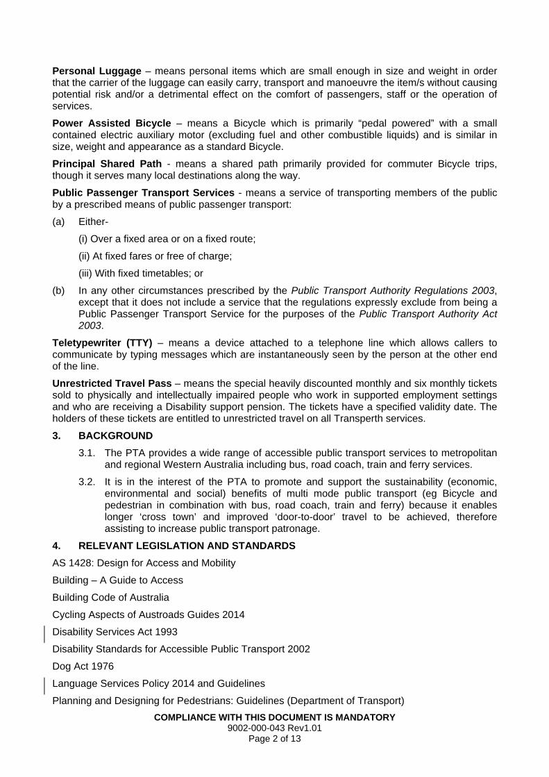
COMPLIANCE WITH THIS DOCUMENT IS MANDATORY 9002-000-043 Rev1.01
Page 2 of 13
Personal Luggage – means personal items which are small enough in size and weight in order that the carrier of the luggage can easily carry, transport and manoeuvre the item/s without causing potential risk and/or a detrimental effect on the comfort of passengers, staff or the operation of services.
Power Assisted Bicycle – means a Bicycle which is primarily “pedal powered” with a small contained electric auxiliary motor (excluding fuel and other combustible liquids) and is similar in size, weight and appearance as a standard Bicycle.
Principal Shared Path - means a shared path primarily provided for commuter Bicycle trips, though it serves many local destinations along the way.
Public Passenger Transport Services - means a service of transporting members of the public by a prescribed means of public passenger transport:
(a) Either-
(i) Over a fixed area or on a fixed route;
(ii) At fixed fares or free of charge;
(iii) With fixed timetables; or
(b) In any other circumstances prescribed by the Public Transport Authority Regulations 2003, except that it does not include a service that the regulations expressly exclude from being a Public Passenger Transport Service for the purposes of the Public Transport Authority Act 2003.
Teletypewriter (TTY) – means a device attached to a telephone line which allows callers to communicate by typing messages which are instantaneously seen by the person at the other end of the line.
Unrestricted Travel Pass – means the special heavily discounted monthly and six monthly tickets sold to physically and intellectually impaired people who work in supported employment settings and who are receiving a Disability support pension. The tickets have a specified validity date. The holders of these tickets are entitled to unrestricted travel on all Transperth services.
3. BACKGROUND
3.1. The PTA provides a wide range of accessible public transport services to metropolitan and regional Western Australia including bus, road coach, train and ferry services.
3.2. It is in the interest of the PTA to promote and support the sustainability (economic, environmental and social) benefits of multi mode public transport (eg Bicycle and pedestrian in combination with bus, road coach, train and ferry) because it enables longer ‘cross town’ and improved ‘door-to-door’ travel to be achieved, therefore assisting to increase public transport patronage.
4. RELEVANT LEGISLATION AND STANDARDS
AS 1428: Design for Access and Mobility
Building – A Guide to Access
Building Code of Australia
Cycling Aspects of Austroads Guides 2014
Disability Services Act 1993
Disability Standards for Accessible Public Transport 2002
Dog Act 1976
Language Services Policy 2014 and Guidelines
Planning and Designing for Pedestrians: Guidelines (Department of Transport)
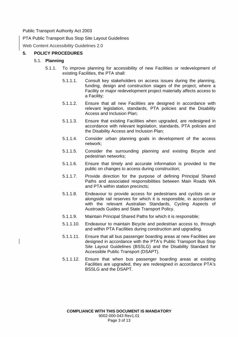
COMPLIANCE WITH THIS DOCUMENT IS MANDATORY 9002-000-043 Rev1.01
Page 3 of 13
Public Transport Authority Act 2003
PTA Public Transport Bus Stop Site Layout Guidelines
Web Content Accessibility Guidelines 2.0
5. POLICY PROCEDURES
5.1. Planning
5.1.1. To improve planning for accessibility of new Facilities or redevelopment of existing Facilities, the PTA shall:
5.1.1.1. Consult key stakeholders on access issues during the planning, funding, design and construction stages of the project, where a Facility or major redevelopment project materially affects access to a Facility;
5.1.1.2. Ensure that all new Facilities are designed in accordance with relevant legislation, standards, PTA policies and the Disability Access and Inclusion Plan;
5.1.1.3. Ensure that existing Facilities when upgraded, are redesigned in accordance with relevant legislation, standards, PTA policies and the Disability Access and Inclusion Plan;
5.1.1.4. Consider urban planning goals in development of the access network;
5.1.1.5. Consider the surrounding planning and existing Bicycle and pedestrian networks;
5.1.1.6. Ensure that timely and accurate information is provided to the public on changes to access during construction;
5.1.1.7. Provide direction for the purpose of defining Principal Shared Paths and associated responsibilities between Main Roads WA and PTA within station precincts;
5.1.1.8. Endeavour to provide access for pedestrians and cyclists on or alongside rail reserves for which it is responsible, in accordance with the relevant Australian Standards, Cycling Aspects of Austroads Guides and State Transport Policy.
5.1.1.9. Maintain Principal Shared Paths for which it is responsible;
5.1.1.10. Endeavour to maintain Bicycle and pedestrian access to, through and within PTA Facilities during construction and upgrading.
5.1.1.11. Ensure that all bus passenger boarding areas at new Facilities are designed in accordance with the PTA’s Public Transport Bus Stop Site Layout Guidelines (BSSLG) and the Disability Standard for Accessible Public Transport (DSAPT).
5.1.1.12. Ensure that when bus passenger boarding areas at existing Facilities are upgraded, they are redesigned in accordance PTA’s BSSLG and the DSAPT.
COMPLIANCE WITH THIS DOCUMENT IS MANDATORY 9002-000-043 Rev1.01
Page 4 of 13
5.2. Infrastructure
5.2.1. Accessible Parking for People with a Disability
5.2.1.1. The PTA shall provide parking for people with disabilities at PTA Facilities as they are built or upgraded in accordance with the Building Code of Australia and Building – A Guide to Access and other required Standards.
5.2.1.2. Only a vehicle displaying an ACROD Permit is permitted to park in a disabled parking bay.
5.2.1.3. The PTA shall review the number of disabled parking bays at each station depending on demand.
5.2.2. Parking for Bicycles
5.2.2.1. The PTA shall provide parking for Bicycles at PTA Facilities as they are built or upgraded and as determined by demand at individual stations with the exception of the Perth Underground Station, special events stations, Transwa stations and stopping places.
5.2.2.2. Bicycle parking, where provided, shall:
a. Comprise of U rails, Enclosures and/or lockers;
b. Be located as close as practicable to the main entrance to the Facility, and linked to an accessible path;
c. Be on level ground with a firm, non-slip surface, clearly signposted and unobstructed; and
d. Where practicable, be located so as not to require the user to cross any regular route or road used by cars, buses or other road vehicles within the PTA property boundary.
5.2.2.3. The security of Bicycles and Mobility Aids shall be the sole responsibility of the Bicycle or Mobility Aid owner.
5.2.3. Access Paths
5.2.3.1. The PTA will design access paths to meet the requirements of:
a. The DSAPT;
b. Planning and Designing for Pedestrians: Guidelines; and
c. Cycling Aspects of Austroads Guide.
5.2.4. Bus Stops
5.2.4.1. The PTA will comply with the BSSLG and DSAPT when designing, building or upgrading any bus passenger boarding area located on the road reserve or within a PTA Facility to facilitate the effective and safe operation of bus public transport services for both metropolitan (Transperth) and regional (major country town) regular transport services. The PTA shall arrange for public bus stops to be progressively reviewed and upgraded on a priority and an as needs basis, subject to budget and resource availability in accordance with its obligations under the DSAPT.
COMPLIANCE WITH THIS DOCUMENT IS MANDATORY 9002-000-043 Rev1.01
Page 5 of 13
5.2.4.2. Where possible, the PTA will progressively upgrade bus stops to ensure there is:
a. A boarding point for each bus stop, which is in the area immediately adjacent to a bus stop pole or sign, that facilitates the safe boarding and alighting of passengers;
b. A correctly positioned bus stop pole or sign;
c. A level concrete hardstand area at correct kerb height to facilitate safe operation of bus boarding ramp systems; and
d. Tactile ground surface indicators installed at the boarding point.
5.2.4.3. Where applicable, the PTA will provide up to three metres of connecting pathway, and provide funding to Local Government for 50% of the cost of additional pathway requirements, subject to such requests meeting the requirements of the PTA’s Pathways Subsidy Program.
5.2.5. Bus Shelters
5.2.5.1. PTA is not responsible for the provision of bus shelters unless located within a PTA Facility.
5.2.5.2. If Local Government or another entity proposes to install bus shelters, they must comply with the BSSLG and DSAPT.
5.2.6. Any items of discretionary infrastructure (including but not limited to bins and seats) installed on a road reserve within any immediate bus stop area, are the responsibility of Local Government and outside of the PTA’s obligations. Where discretionary infrastructure is installed at a bus stop by Local Government or another entity, the installation of this discretionary infrastructure must comply with the BSSLG.
5.2.7. Lifts
5.2.7.1. The PTA shall maintain lifts in good working order as far as practical.
5.2.7.2. When lifts are “out of order” and assistance is required, people with a Disability shall have the following options available to them:
a. Contact the Central Monitoring Room (which is staffed 24 hours a day, 365 days a year) by calling 9220 9999; or
b. Activate the emergency call button on the Communication module in the lift or emergency button located outside the lift on the bus platform, for instructions.
c. Passengers may board the next train and alight at the next station, no ticket is required for this trip.
d. If requested the PTA will arrange and pay for a taxi to transport the passenger with a Disability from the Facility to an agreed destination.
COMPLIANCE WITH THIS DOCUMENT IS MANDATORY 9002-000-043 Rev1.01
Page 6 of 13
5.3. Services
5.3.1. The PTA shall provide information on its accessibility services to support and assist passengers. These services include:
5.3.1.1. Transperth
a. Infoline 13 62 13 to provide information on accessible public transport services, SmartRider assistance, brochures, timetables, and register complaints, suggestions and feedback;
b. Hearing impaired people who have access to a Telephone Typewriter (TTY) machine may call 13 36 77 and quote the Transperth InfoLine on 13 62 13;
c. Communication Cards to assist passengers with language difficulties to communicate with Transperth personnel;
d. Large print and Braille Timetables for all services are available upon request.
5.3.1.2. Transwa
a. Transwa 1300 662 205 to provide information on accessible public transport services, customer service assistance, brochures, timetables and register, complaints, suggestions and feedback;
b. Hearing impaired people who have access to a TTY machine may call 13 36 77 and quote the Transwa telephone number 1300 662 205;
c. A Commentline service (13 16 08) shall be provided for passengers to provide suggestions or feedback regarding Transwa services; and
d. A Customer Service Enquiry email address at [email protected].
5.3.1.3. The PTA shall ensure, as far as is reasonably practicable, that access to its online information for both external websites as well as its intranet (Transnet), complies with the requirements of the Web Content Accessibility Guidelines (WCAG) 2.0 Level A. Where the requirement is not currently met, alternative means of providing information to stakeholders shall be made available, in accordance with PTA Disability Access and Inclusion Plan.
5.3.1.4. PTA business areas responsible for the management of websites shall provide for WCAG 2.0 Level A compliance in the delivery of major system or content upgrades and at the design stage for new websites.
5.3.2. The PTA shall endeavour to provide language services to allow effective communication in written and/or spoken English by:
5.3.2.1. Providing access to Translating or Interpreting Services (TIS) 13 14 50 for the hearing impaired passengers that need language assistance or to assist passengers who are unable to adequately communicate in English;
5.3.2.2. Providing the TIS number on publications and websites;
COMPLIANCE WITH THIS DOCUMENT IS MANDATORY 9002-000-043 Rev1.01
Page 7 of 13
5.3.2.3. Endeavouring to provide key information in key languages on the websites.
5.3.3. Transperth bus and ferry services shall endeavour to provide agreed assistance to people with a Disability provided that passengers contact the Transperth InfoLine and provide adequate notice. This assistance includes:
5.3.3.1. Provision of ramps to cross jetty-ferry gaps;
5.3.3.2. Provision of automatic ramps and kerbside ‘kneeling’ to help passengers embark and disembark from accessible buses; and
5.3.3.3. Bus routes serviced by low floor accessible buses are identified on timetables by route number. The PTA will endeavour to progressively increase the number of bus route services by accessible buses, as more accessible buses are introduced into operation.
5.3.4. Transperth Train Operations shall endeavour to provide agreed assistance to people with a Disability provided that passengers give one hour’s notice by contacting Transperth Customer Service on 1800 800 022. This assistance includes:
5.3.4.1. Provision of ramps to cross platform-train gaps; and
5.3.4.2. Helping passengers to embark and disembark from the train.
5.3.5. Transwa shall endeavour to provide agreed assistance to people with Disability when bookings are made at least 48 hours prior to travel, via the Transwa Reservations Contact Centre on 1300 662 205. This assistance may include:
5.3.5.1. Provision of side lifts on road coaches which can raise passengers with Disability and their Mobility Aid in and out of the coach;
5.3.5.2. Passengers with Disability travelling on Transwa trains and road coaches may remain in their Mobility Aid with brakes applied and where applicable will be anchored into position;
5.3.5.3. Passengers with Disability travelling on Transwa trains and road coaches may choose to transfer to a standard seat and have the Mobility Aid carried in the designated area (subject to size restrictions and availability of space);
5.3.5.4. Provision of wheelchairs at Albany, Armadale, Bunbury, East Perth, Esperance, Geraldton, Kalgoorlie, Midland and Northam Stations, to assist passengers with a Disability when embarking or disembarking the road coach; and
5.3.5.5. Provision of ramps to cross platform/train gaps.
5.4. Assistance Dogs
5.4.1. The PTA shall allow Assistance Dogs and Assistance Dogs-In-Training that have been approved by the Department of Local Government and Communities (DLGC) in accordance with the Dog Act 1976 to be in a Facility or Conveyance.
COMPLIANCE WITH THIS DOCUMENT IS MANDATORY 9002-000-043 Rev1.01
Page 8 of 13
5.4.2. The PTA shall automatically grant access rights to Assistance Dogs trained and accredited by the following recognised organisations as prescribed under the Dog Regulations 2013 to be in a Facility or Conveyance including:
5.4.2.1. Assistance Dogs Australia;
5.4.2.2. Lions Hearing Dogs;
5.4.2.3. Seeing Eye Dogs Australia; and
5.4.2.4. Royal Guide Dogs Association and affiliated bodies (including Seeing Eye Dogs Australia and Visability).
5.4.3. Applications for approval for Assistance Dogs and Assistance Dogs-In-Training shall be made through the DLGC in accordance with its ‘Assistance Dog Approvals Policy and Application’.
5.4.4. In assessing an application for an Assistance Dog or Assistance Dog-In Training, the DLGC shall consider the safety of PTA employees as well as the safety and comfort of the travelling public, in accordance with the requirements set out in Annex A.
5.4.5. The DLGC shall notify the PTA of Assistance Dogs approvals and consult with the PTA on any changes relating to the approval process for Assistance Dogs.
5.4.6. Assistance Dogs and Assistance Dogs-In-Training that are permitted on PTA Facilities and Conveyances must:
5.4.6.1. be clearly identified by a suitably marked dog coat or harness; and
5.4.6.2. carry and produce on demand:
a. a valid photo identification card of the Assistance Dog or Assistance Dog-In-Training issued by a recognised organisation listed in clause 5.4.2 or the DLGC at all times when using public transport;
b. a Transperth Travel Pass for the Vision Impaired and accompanying guide;
c. an Orientation and Mobility Assistance Travel Pass, for instructors to conduct training on Transperth services for person with a visual impairment and Guide Dogs; or
d. for interstate holders of a Vision Impaired Travel Pass, a Transperth Travel Pass which can be obtained from Transperth.
5.4.7. Access may be refused to public transport where the Assistance Dog does not meet the requirements stated in clause 5.4.1 to 5.4.6.
5.4.8. The PTA may also disallow Assistance Dogs and Assistance Dogs-In-Training to be in a Facility or Conveyance if:
5.4.8.1. There is reason to believe the Assistance Dog and Assistance Dog-In-Training has an infectious disease which could likely jeopardise public health or the health of other animals;
5.4.8.2. The Assistance Dog and Assistance Dog-In-Training displays behaviour that breaches the standard of behaviour required of an Assistance Dog and Assistance Dog-In-Training including:
a. causing any distress or inconvenience to other customers or staff; or
COMPLIANCE WITH THIS DOCUMENT IS MANDATORY 9002-000-043 Rev1.01
Page 9 of 13
b. causing any risk to the health, safety and welfare of any employee or any other person whilst travelling on public transport and/or the Facility or Conveyance.
5.5. Mobility Aids
5.5.1. Mobility Aids used on PTA services and Facilities must meet the following criteria:
5.5.1.1. Fit within an allocated space of 1300mm in length by 800mm wide, (unless travelling in the Australind where a Mobility Aid must be able to fit into an allocated space of 1300mm in length by 740mm wide);
5.5.1.2. Be no more than 750mm wide and 1600mm high (unless travelling in the Australind, the Mobility Aid must be no more than 690mm wide, and no more than 850mm high on Road Coaches);
5.5.1.3. Weigh less than 300kg including the aid, occupant and assistant (if applicable) when using a ramp or other boarding devices;
5.5.1.4. Have effective braking systems to maintain stability;
5.5.1.5. Turn 180 degrees within an area 2070mm by 1540mm;
5.5.1.6. Cross a horizontal gap up to 50mm wide and mount a vertical rise (bump) up to 15mm;
5.5.1.7. Negotiate a 1:14 grade ramp unassisted and a 1:4 grade ramp with assistance;
5.5.1.8. Negotiate a 1:8 grade where the ramp is less than 1520mm long;
5.5.1.9. Cross a gap up to 75 mm wide when accessing pedestrian level crossings; and
5.5.1.10. Cross grating gaps up to 13mm wide and 150mm long.
5.5.2. Mobility Aids and Bicycles (as defined in Clause 2) are the only forms of mobile transit assistance permitted on services. All other items such as children’s scooters, roller skates/blades, etc are not permitted to be used at stations or Conveyances however may be carried on board as Personal Luggage.
5.6. Bicycles
5.6.1. To improve accessibility for all passengers with Bicycles, the PTA shall:
5.6.1.1. Allow Bicycles (including Power Assisted Bicycles) on its Transperth ferry services at any time;
5.6.1.2. Allow Bicycles (including Power Assisted Bicycles) on Transperth trains at all times with the exception of peak times (7am - 9am and 4.30pm - 6.30pm Monday to Friday) when travelling in peak flow direction (i.e. towards Perth CBD in the morning and away from Perth CBD in the afternoon/evening);
5.6.1.3. Allow fold-up Bicycles within an Approved Carry Bag on Transperth trains, buses, Transwa road coaches and trains (in lieu of the free luggage allowance or for an additional fee) at any time. The fold-up Bicycle must remain folded and in the bag whilst on:
a. Transperth bus services at all times; and
b. Transperth train services during peak and in peak direction.
COMPLIANCE WITH THIS DOCUMENT IS MANDATORY 9002-000-043 Rev1.01
Page 10 of 13
5.6.1.4. Allow passengers to travel with a Bicycle (including Power Assisted Bicycles) on a Transperth train, in a counter flow direction (i.e.- away from Perth CBD in the morning or towards Perth CBD in the afternoon) during peak times on Monday to Friday but, in doing so, the passenger shall not travel any closer to the Perth CBD than the Canning Bridge, McIver, City West or Leederville Station;
5.6.1.5. Allow two Bicycles on all Transwa road coach and train services (Prospector and contracted coach services excluded) with payment of applicable fees. For Australind services, Bicycles must be carried ‘end to end.’ i.e. Bicycles are put on at Perth and taken off at Bunbury or vice versa;
5.6.1.6. Allow more than two Bicycles to be transported on Transwa road coach services provided space permits (some restrictions apply);
5.6.1.7. Install end of Bicycle trip Facilities at all PTA work places, where practicable and according to demand; and
5.6.1.8. Endeavour to maintain an awareness of current cycling requirements in conjunction with established project consultation processes.
5.6.2. Notwithstanding clause 5.6.1.2 and 5.6.1.4, the Executive Director Transperth System, Regional Town and School Bus Services may in writing, authorise a named person to travel with a Bicycle.
5.6.3. An authority under clause 5.6.2, may be given subject to conditions and limitations as the Executive Director Transperth System, Regional Town and School Bus Services thinks fit, and may at any time be amended or revoked.
5.6.4. A security officer, an authorised person, or a member of the Western Australia Police may direct that a person who is about to board the train, road coach bus or ferry with a Bicycle (other than a fold up Bicycle) is not to board that the train, road coach bus or ferry with a Bicycle.
5.6.5. A person who is in a passenger train carriage with a Bicycle shall disembark if:
5.6.5.1. The particular carriage is crowded;
5.6.5.2. The particular carriage will be crowded; or
5.6.5.3. The crowding is due to an event causing high demands on the urban passenger train system (e.g. Australia Day celebrations, Royal Show, Christmas pageants, sporting events or entertainment events).
5.6.6. Non-fold up Bicycles or fold-up Bicycles not in an Approved Carry Bag are not permitted on Transperth buses at any time.
5.6.7. Bicycles must not be ridden on train or bus station platforms or ramps at any time.
5.6.8. Bicycles fitted with obtrusive features are not permitted on any Transperth or Transwa service.
5.7. Concession Passes
5.7.1. Transperth and Transwa recognise and accept a range of concession passes to improve the accessibility of public transport for passengers.
5.7.2. Information on the types of concession passes and the relevant eligibility criteria are available on the Transperth and Transwa websites.
COMPLIANCE WITH THIS DOCUMENT IS MANDATORY 9002-000-043 Rev1.01
Page 11 of 13
5.7.3. A support person travelling with a Companion Card holder is entitled to free travel on public transport. The Companion Card holder must have a valid ticket.
5.7.4. Applications for a special exemption where a person does not work in a support employment setting but is in receipt of a Disability Support Pension, and has a physical or intellectual impairment such that they cannot understand the fare structure, handle cash or use the SmartRider ticketing system must be supported by:
5.7.4.1. A certificate from a Disability Sector Organisation and/or health professional confirming the passenger’s medically recognised Disability and incapacity to use normal ticketing; and
5.7.4.2. A written letter from a Transperth approved organisation on behalf of the person concerned for the issue of an Unrestricted Travel Pass.
5.8. Infringement Notices
5.8.1. Infringement notices are issued under Public Transport Authority Regulations 2003 to customers for offences including travelling without a valid standard ticket or travel pass, a valid concession entitlement, an incorrect ticket or who have not paid for their entire journey.
5.8.2. The PTA Coordinator Transit Support or delegate shall cross reference infringement notices with the Transperth Unrestricted Travel Pass Register prior to registering unpaid infringement notices with the Fines Enforcement Registry.
5.8.3. Where an infringement notice has been issued to a person as a result of failure to carry an Unrestricted Travel Pass, and the person is listed on the Transperth Unrestricted Travel Register, the PTA Coordinator Transit Support or delegate shall revoke the notice.
5.8.4. Applications to contest an infringement notice may be made on medical grounds but must be supported by:
5.8.4.1. A certificate from a medical practitioner confirming the passenger’s medically recognised Disability; and
5.8.4.2. A letter of appeal by or on behalf of the person concerned for the infringement notice.
5.8.5. Information on infringement notices and the appeals process is available on the Transperth website.
5.9. Education
5.9.1. The PTA recognises the importance of continuing to work closely with Disability groups to further improve the accessibility of PTA services for people with a Disability.
5.9.2. Transperth shall implement the Transperth’s “Get on Board” Education Program for Communities and proactively seek out forums to work directly with local indigenous, multicultural and Disability service delivery organisations, associations and networks, government agencies and non-government organisations, groups and families to provide demonstrations, training and presentations on how to safely use the public transport system.
COMPLIANCE WITH THIS DOCUMENT IS MANDATORY 9002-000-043 Rev1.01
Page 12 of 13
RELATED POLICIES
PTA Architectural Design Guide
PTA Disability Access and Inclusion Plan 2012-2017
PTA Public Transport Bus Stop Site Layout Policy
POLICY OWNER
Executive Director Safety and Strategic Development
ACTIVE DATE
March 2017
REVIEW DATE
March 2020
Mark Burgess
MANAGING DIRECTOR

ANNEX A TO ACCESSIBILITY POLICY
COMPLIANCE WITH THIS DOCUMENT IS MANDATORY 9002-000-043 Rev1.01
Page 13 of 13
Criteria for Approving Assistance Dogs
Note: The requirements of Annex A do not apply to Assistance Dogs trained by recognised organisations which are automatically granted access rights, as prescribed under the Dog Regulations 2013.
All applications for Assistance Dogs and Assistance Dogs-In-Training must be made through the Department of Local Government and Communities in accordance with its ‘Assistance Dog Approvals Policy and Application’ and must include the following:
a) An electronic copy of an easily identifiable photograph of the Assistance Dogs or Assistance Dogs-In-Training;
b) The name of the person who will be handling the Assistance Dogs or Assistance Dogs-In-Training;
c) A written statement from an Independent Public Access Test Assessor confirming the Assistance Dogs or Assistance Dogs-In-Training has been trained to achieve the following:
A high standard of appropriate behaviour fit for a public place;
A high standard of hygiene fit for a public place;
Experience in real life situations;
Non-barking behaviour;
Toileting on command;
Travelling in confined spaces on all forms of public transport;
No reaction to noise, crowds and stressful situations;
Bark on command if it needs to attract attention for help; and
Three different tasks that alleviate the owner’s disability (name the tasks).
d) A certificate from a medical practitioner, allied health professional or disability service provider confirming the person’s disability and how the Assistance Dog alleviates the effects of that Disability.
e) A Veterinarian Declaration that the Assistance Dog:
- Displays standards of hygiene that are appropriate for a public place and public transport.
- Is of good health and has no infectious diseases.
- Displays standards of behaviour that are appropriate for a public place and public transport.
- Responds to control and obedience commands.
Belmont Station Development Application Report 59