ben houston camden mendiola dan “klitz” johnson dan rice monty prekeris
TRANSCRIPT

FLyNET
Ben Houston
Camden Mendiola
Dan “Klitz” Johnson
Dan Rice
Monty Prekeris
MISSION STATEMENT
To provide a flexible low power wireless aerial/terrestrial network that allows the user to survey, sense, and respond.
Useful for military, police, search and rescue, and/or back country navigation
Localized and self managed.
Camden

OBJECTIVE
To design and implement an autonomous quad-copter platform that can remotely sense and relay data to a base station
To utilize the IEEE 802.15.4 protocol to create a low power mesh network
Camden

TEAM GOALS
Secondary: • Autonomous flight with mesh network integration. • Advanced sensor integration.
Primary: • Manual flight through keyboard remote control.• Basic autonomous flight pattern. • Wireless Zigbee Comm. Bridge Station
Elevated: • GPS navigation and obstacle avoidance. • Integration of more sensors.
Camden

Command StationXBee
Command Station
PC
BLOCK DIAGRAM OVERVIEW
XBee
FlightSensors& GPS
Third CommModule
Environmental Sensors
Motors
XBee
FlightSensors& GPS
Quad-copterATMega
2560
Environmental Sensors
Motors
Camden

AUTONOMOUS FLIGHT FUNCTIONALITY
Manual Flight
Command
Locate unoccupied air space
Perform Autonomous Flight Pattern
Manual Return Flight
Assert UAV Mode and Input GPS
Point
Autonomous Navigation
to GPS Point
Perform Autonomous
Flight Pattern
Autonomous Return
Navigation
SECONDARY GOAL
ELEVATED GOAL
Camden

SYSTEMS OVERVIEW
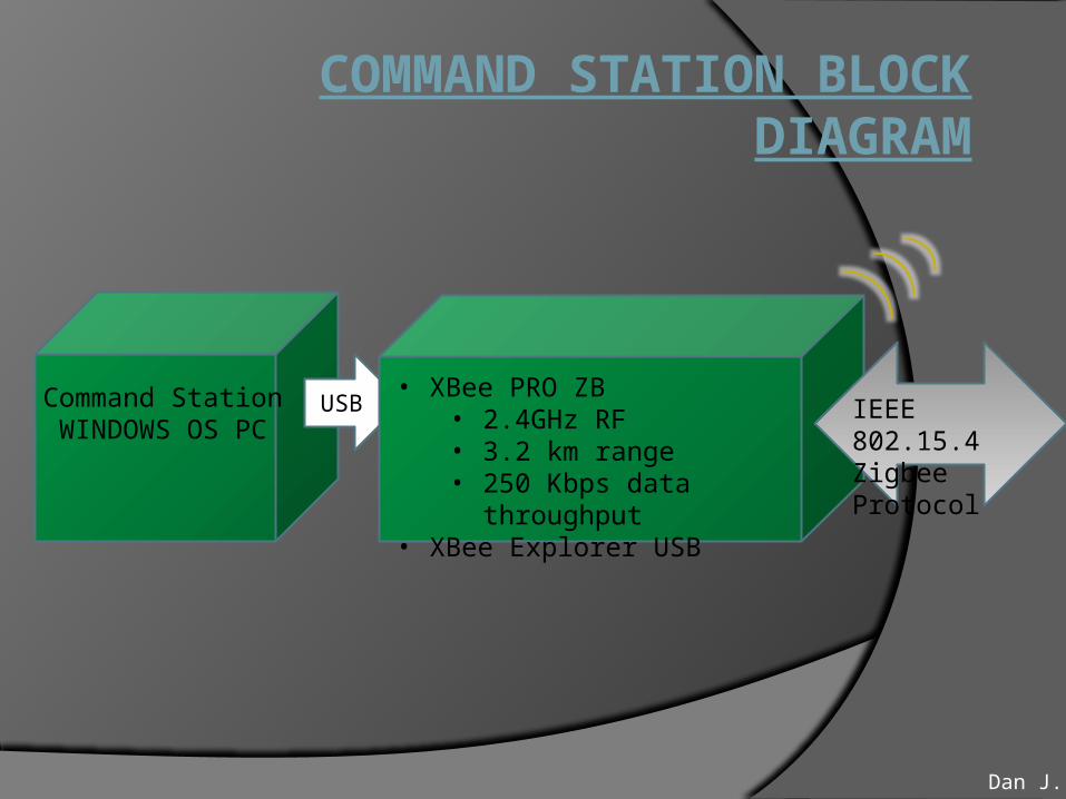
COMMAND STATION BLOCK DIAGRAM
• XBee PRO ZB• 2.4GHz RF• 3.2 km range• 250 Kbps data throughput
• XBee Explorer USB
Command StationWINDOWS OS PC
USB IEEE 802.15.4Zigbee Protocol
Dan J.

XBee(Serial)
Flight Sensors
Flight Sensors:• Barometer – BMP085• Magnetometer – HMC5843• Accelerometer – ADXL345• Gyro – ITG3200• Ultrasonic range finder – Daventech SFR10• GPS – USGlobalSat EM-408• I2C
Motors• E-Flight Brushless• 1020Kv• 22A max continuous• 2lb nominal payload/motor
Environmental Sensors (tentative):• Temperature• Gas• CMOS Camera - TCM8230MD
30A ESC’s:• Allows 35,000 rpm• 40A for 10s Burst• PWM
Env. Sensors
CopterATMEGA
2560ZigBee
ESC
Motors
Dan J.

Terrestrial UnitTemperatureChemical SensingPerson
○ Heart Rate
Second Quad CopterMirror functionality of former
Quad-Copters
Dan J.

POWER SYSTEM• Battery – 11.1 V, 8000mAh High Discharge Li-Po Battery
• Power Rails – 5V rail for the ATMega 2560, 3.3V for Sensors and XBee
• MC33269 Voltage Regulator – takes 12V to 5V
• Logic Level converter – converts 5V to 3.3V for input to XBee and 3.3V to 5V for signals output from XBee
• Battery Monitor – checks the status of the battery voltage and signals a warning if it is too low. If the battery supply voltage drops even further, the Quadcopter will begin to land.
• ESCs (Electronic Speed Controller) – Convert PWM signals from the ATMega2560 into signals for the brushless motors.
Dan J.

FLIGHT SENSORSFlight Sensors(Primary):• Barometer – Used to measure atmospheric pressure. Allows the flight control to determine
height of the Quadcopter and attempt to increase power to motors in order to maintain altitude.
• Magnetometer – Measures the strength of the Earth’s magnet field to get the heading of the Quadcopter
• Accelerometer – Measures acceleration of the Quadcopter along the x, y, z axes.
• Gyro – Measures radial velocity in terms of roll, pitch, and yaw.
Flight Sensors(Secondary):• Ultrasonic range finder – Determines distance objects are away from the sensor. Can be used to
avoid objects that come within range of the Quadcopter. Can also be used to aid in landing.
• GPS – Gets longitude and latitude coordinates from a satellite which allows the Quadcopter to determine a flight path to its desired location
Dan J.


ENVIRONMENTAL SENSORS
• Temperature Sensor – Analog output. (Primary)
• Gas Sensors – CO, Methane, Hydrogen gas. Analog Output. (Elevated)
• CMOS Camera – Communicates using I2C. (Elevated)
• Heart rate monitor – Uses a Polar transmitter and communicates through I2C. (Elevated)
Dan R.

SENSOR RISK AND CONTINGENCY PLAN
Ultrasonic Multiple Ultrasonic sensors may cause interference with one another
○ Alternate sets of opposing sensors to fire at different times. Wide beam width may cause unexpected detection
○ Size down the beam width and use more sensors Motor interference
○ Relocate sensors Barometer
Propeller interfering with air pressure○ Encapsulate barometer or shield it from motors
CMOS Camera Exceed XBee bandwidth
○ Use high compression○ Stream at lower frames per second ○ Store images locally Dan R.

WIRELESS COMMUNICATION
Ben

XBee COMMUNICATION PLATFORM
Ad hoc On-demand Distance Vector (AODV) Mesh Routing Allows data packets to traverse multiple nodes (hops) from
source to destination Does not necessarily have to be routed through the
coordinator AODV Routing Algorithm dictates ever changing and
locally stored look up table of nearest one hop neighbors
Ben

Digi International has designed the Xbees in a way that allows a PAN to include up to 40 drop-in radio devices in an Ad Hoc configuration.
Ease of use when building a large self healing network.
DROP-IN NETWORKS
Ben

ZB Pro RF data throughput: 250 kbps Line of site range: 3.2 km Serial Flow Control via RTS and CTS pins Encryption (adds latency) Sleep Mode(s) Ability to self manage digital and analog sensors Application Program Interface
ADVANCED XBee FEATURES
Ben

XBee API(APPLICATION PROGRAM INTERFACE)
The API specifies how commands, command responses and module status messages are sent and received from the module using a UART Data Frame.
Follows IEEE 802.15.4 standard Useful for software design 84 byte payload Multiple command features
Ben

XBee Software
Software drivers contain algorithms that can build or parse API packets
Payloads can contain the following data:Radio Addresses12 bits of analog sensor data converted to
digital at the XBee hardware levelCommand Status bytes AT commands
Embedded System Experience
Ben

RisksSignal InterferenceRangePower ConsumptionBandwidth
ContingencyXBee-PRO® ZB Wall Routers
○ Extends signal strength and range of an XBee ZB mesh network
○ Creates additional network pathways for more reliable mesh networking
Adjust Sleep Mode settings via XBee firmwareLimit amount of simultaneous data output
XBee RISK AND CONTINGENCIES
Ben

FLIGHT CONTROL SYSTEM
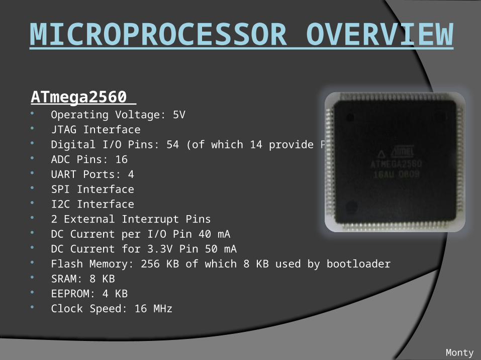
ATmega2560 Operating Voltage: 5V JTAG Interface Digital I/O Pins: 54 (of which 14 provide PWM output) ADC Pins: 16 UART Ports: 4 SPI Interface I2C Interface 2 External Interrupt Pins DC Current per I/O Pin 40 mA DC Current for 3.3V Pin 50 mA Flash Memory: 256 KB of which 8 KB used by bootloader SRAM: 8 KB EEPROM: 4 KB Clock Speed: 16 MHz
MICROPROCESSOR OVERVIEW
Monty

Eclipse C/C++ Dev environment for Arduino MegaAllows for parallel development of flight
programs and control during PCB development ATMEL Professional Dev Suite intended
for low level debugging though JTAGNeed access to JTAG pin outs which the
Arduino Mega does not give access toEmulator AVR JTAG ICE
device will be used
DEVELOPMENT ENVIRONMENT
Monty

200Hz• Read Gyro• Read Accelerometer
100Hz• Flight Controls (Stabilization routines)
50Hz• Process Telemetry
25Hz• Read Barometer
10Hz• Read Battery• Process Compass
SOFTWARE TASK SCHEDULER
Monty

MOTOR CONTROL SYSTEM
PIDATmega MOTORSChange ofPosition
SENSOR RESPONSE
Monty
Task Scheduling – Addition of sensors consumes clock cyclesScheduling sensors in order of priorityCircumvent processer and straight to XBeeCo-ProcessorHard Real Time System – Sam
Monty

LOGISTICS

FLYNET QUAD FRAME
• Prototype Frame: Made from Balsa, Poplar and Oak.
• Aluminum Frame: Aeroquad frame that is more robust. • Future Frames: A Carbon Fiber or Fiberglass frame could be used, as these are lightweight at the risk of durability
Dan R.
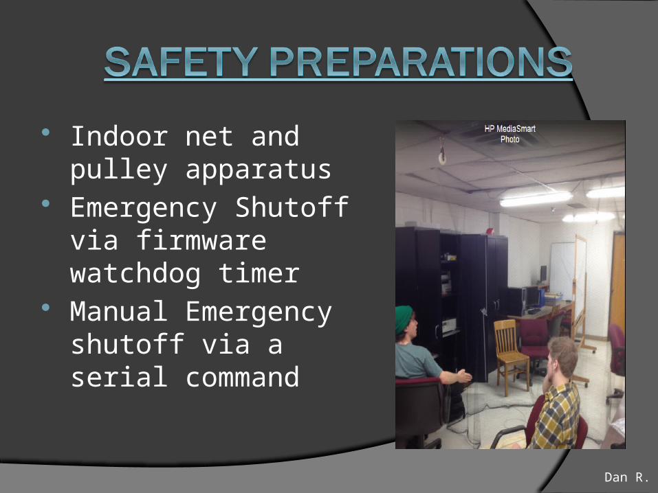
Indoor net and pulley apparatus
Emergency Shutoff via firmware watchdog timer
Manual Emergency shutoff via a serial command
Dan R.

DIVISION OF LABOR
Phase 1: Ben Camden Daniel Klitz MontyPCB Design Flight Command Phase 2:
PCB Revision and Design Environmental Sensor *Hardware design *Software design XBee Mesh Network Phase 3: Basic Auto PatternsGPS Integration
Dan R.

SCHEDULE
Dan R.

RISK AND CONTINGENCY
PLAN• Frame
• Plan to buy Aluminum frame in the future. If it is not available, we may have to make it ourselves.
• Schedule uncertainty• Current timeline does not incorporate weekends.
• Availability of components• Utilize multiple distributers
• Code Sharing• Tortoise SVN with revision control
• Broken Parts• Backup Parts on hand (Propellers)
Dan R.

BUDGETComponent # Price
E-Flite 480 Brushless Motors 4 $54 each
Hobbywing Pentium 30A ESCs 4 $23 each
Accelerometer ADXL-345 1 $15
Magnetometer HMC-5843 1 $15
Barometer BMP-085 1 $20
Gyro ITG-3200 1 $50
XBee ZB Pro 2.4GHz 3 $40 each
Arduino Mega2560 Temp Dev. Boards 2 $50 each
Safe Testing Apparatus 1 $75
8000 mAH LiPo Battery 1 $55
Revision 1 Frame Materials 1 $30
Revision 2 Aluminum Frame 1 $225
PCB Orders 3 $65 each
ATMega 2560 QFP Processors 2 $20 each
US GlobalSat EM-408 GPS Module 1 Free, Thanks Nate Bernstein
Other Sensors (Gas, Heartrate, Camera, etc) 1 $20 - $100 eachDan R.
BUDGET
Component # Price
Other SMT Board Components 3 $50 each
Total (Not including tentative high level sensors) ~ $1400
Funding:
-UROP -EEF (possible)-Sponsorship through Elintrix
Dan R.

QUESTIONS?