benni mini workshop manual 2013 cap 2
DESCRIPTION
CAPITULO 2TRANSCRIPT
Benni Mini 2013.01
Chassis
GROUP
2
2.1 Suspension System
2.1.1 Suspension System - General Information ....................................................................... 2.1.1-1
2.1.2 Front Suspension.............................................................................................................. 2.1.2-1
2.1.3 Rear Suspension .............................................................................................................. 2.1.3-1
2.1.4 Wheels and Tires .............................................................................................................. 2.1.4-1
2.2 Driveline System
2.2.1Driverline System - General Information............................................................................ 2.2.1-1
2.2.2 Driveshaft .......................................................................................................................... 2.2.2-1
2.2.3 Differential ......................................................................................................................... 2.2.3-1
2.3 Brake System
2.3.1 Brake System - General Informa- ..................................................................................... 2.3.1-1
2.3.2 Rear Drum Brake .............................................................................................................. 2.3.2-1
2.3.3 Front Disc Brake ............................................................................................................... 2.3.3-1
2.3.4Parking Brake and Actuation ............................................................................................. 2.3.4-1
2.3.5 Hydraulic Brake Actuation................................................................................................. 2.3.5-1
2.3.6 Power Brake Actuation ..................................................................................................... 2.3.6-1
2.3.7 Anti-lock Control................................................................................................................ 2.3.7-1
2.4 Steering System
2.4.1 Steering System - General Information............................................................................. 2.4.1-1
2.4.2 Power Steering System..................................................................................................... 2.4.2-1
2.4.3 Steering Linkage ............................................................................................................... 2.4.3-1
2.4.4 Steering Column ............................................................................................................... 2.4.4-1
SECTION TITLE Pages


Benni Mini 2013.01
Suspension System
2.1 Suspension System
2012 Benni Mini
2.1.1 Suspension System - General Information
Specifications ................................................................................................................................... 2.1.1-1
General Specifications.............................................................................................................. 2.1.1-1
Description and Operation ............................................................................................................... 2.1.1-2
System Overview...................................................................................................................... 2.1.1-2
General Procedures......................................................................................................................... 2.1.1-4
Wheel Bearing Inspection......................................................................................................... 2.1.1-4
Tie Rod Ball Joint Inspection .................................................................................................... 2.1.1-4
Front Control Arm Ball Joint Inspection .................................................................................... 2.1.1-5
Suspension Device Inspection ................................................................................................. 2.1.1-5
Vehicle Inspection..................................................................................................................... 2.1.1-5
Lift Vehicle Inspection............................................................................................................... 2.1.1-5
Worktable Test .......................................................................................................................... 2.1.1-6
Rear Shock Absorber Inspection.............................................................................................. 2.1.1-6
Road Test ................................................................................................................................. 2.1.1-6
Front Wheel Toe-in Inspection and Adjustment........................................................................ 2.1.1-7
Symptom Diagnosis and Testing...................................................................................................... 2.1.1-8
Inspection and verification ........................................................................................................ 2.1.1-8
Symptom Chart......................................................................................................................... 2.1.1-9
Vehicle Drift Diagnosis............................................................................................................ 2.1.1-14
Abnormal Driving Track Diagnosis (Vehicle Can Not Run Straight) ....................................... 2.1.1-17
Vehicle Swing Diagnosis ........................................................................................................2.1.1-20
Steering Wheel Off Center Diagnosis..................................................................................... 2.1.1-22
Abnormal Driving Track Diagnosis ......................................................................................... 2.1.1-23
Excessive Noise Diagnosis .................................................................................................... 2.1.1-24
Vibration Diagnosis................................................................................................................. 2.1.1-26
Incorrect Tire Wear Diagnosis ................................................................................................ 2.1.1-30
2.1.2 Front Suspension
Specifications ................................................................................................................................... 2.1.2-1
Torque Specifications................................................................................................................ 2.1.2-1
Description and Operation ............................................................................................................... 2.1.2-2
System Overview...................................................................................................................... 2.1.2-2
Table of Contents Pages

Benni Mini 2013.01
Suspension System
Location View............................................................................................................................2.1.2-2
Exploded View ..........................................................................................................................2.1.2-4
Symptom Diagnosis and Testing ......................................................................................................2.1.2-7
Disassembly and Assembly .............................................................................................................2.1.2-8
Strut and Spring Assembly........................................................................................................2.1.2-8
Removal and Installation ................................................................................................................2.1.2-10
Front Control Arm ...................................................................................................................2.1.2-10
Steering Knuckle..................................................................................................................... 2.1.2-11
Bearing ...................................................................................................................................2.1.2-14
Front Strut Assembly ..............................................................................................................2.1.2-16
2.1.3 Rear Suspension
Specifications ...................................................................................................................................2.1.3-1
Torque Specifications................................................................................................................2.1.3-1
Description and Operation................................................................................................................2.1.3-2
System Overview......................................................................................................................2.1.3-2
Location View............................................................................................................................2.1.3-3
Exploded View ..........................................................................................................................2.1.3-4
Symptom Diagnosis and Testing ......................................................................................................2.1.3-6
Removal and Installation ..................................................................................................................2.1.3-7
Rear Axle ..................................................................................................................................2.1.3-7
Rear Wheel Bearing ...............................................................................................................2.1.3-10
Rear Shock Absorber Assembly.............................................................................................2.1.3-12
Stabilizer Bar...........................................................................................................................2.1.3-13
Trailing Arm.............................................................................................................................2.1.3-14
2.1.4 Wheels and Tires
Specifications ...................................................................................................................................2.1.4-1
General Specifications ..............................................................................................................2.1.4-1
Torque Specifications................................................................................................................2.1.4-1
Description and Operation................................................................................................................2.1.4-2
System Overview......................................................................................................................2.1.4-2
Exploded View ..........................................................................................................................2.1.4-3
General Procedures .........................................................................................................................2.1.4-4
Inspection and Identification .....................................................................................................2.1.4-4
Tire Wear Diagnosis .................................................................................................................2.1.4-4
Wheel Runout Inspection..........................................................................................................2.1.4-4
Initial Inspection Before Wheel Alignment ................................................................................2.1.4-5

Benni Mini 2013.01
Suspension System
Tire Wear Inspection................................................................................................................. 2.1.4-6
Symptom Diagnosis and Testing...................................................................................................... 2.1.4-9
Inspection and Verification........................................................................................................ 2.1.4-9
Symptom Chart....................................................................................................................... 2.1.4-10
Removal and Installation................................................................................................................ 2.1.4-12
Wheels and Tires.................................................................................................................... 2.1.4-12


Benni Mini 2013.01
2.1.1-1 2.1.1-1Suspension System - General Information
Specifications
General Specifications
Item Specification
Front wheel alignment parameter
Front toe-in 0°10' ± 0°10
Front wheel camber angle 0.50° ± 0.50°
Front wheel caster angle 2.8° ± 0.5°
Front wheel kingpin inclination angle 12.5° ± 0.5°
Rear wheel alignment parameter
Rear toe-in 0° ( -0°20' ~ 0°20' )
Rear wheel camber angle0° ( -0.33° ~ 0.33°) or -0°20' ~
0°20'
2.1.1 Suspension System - General Information

2.1.1-2
Benni Mini 2013.01
2.1.1-2Suspension System - General Information
Description and Operation
System Overview
The primary aim of vehicle engineering is to
ensure the safety and reliability of steering and
suspension system. Every component should be
of enough strenghth to bear and absorb extreme
shock. Steering system and front & rear suspen-
sion system must keep certain geometrical rela-
tionship with vehicle body.
Steering and suspension system require the front
wheel to return automatically and minimize the
front wheel rolling resistance and road frication
force. It helps users control the vehicle directions
easily and comfortably.
Comprehensive wheel alignment inspection
includes measuring rear wheel front toe-in angle
and camber angle. 4-wheel alignment can make
sure all 4 wheels can turn to the same directions
accurately. After geometrical alignment, vehicle
can get best fuel economics and tire service life
and optimal steering performance.
1. Caster angle
Caster angle refers to the pitch or tip back capac-
ity from the highest point of steering axial line
deviating vertical surface, observed from the lat-
eral of vehicle. Tip back is positive and pitch is
negative. Caster angle influences the direction
control in steering but has no impact on the tire
wear. Too soft spring or overload will influence
caster angle. When the caster angle of the vehi-
cle is positive, pull the vehicle to its center. The
minimal positive caster angle will lead the side-
way and rolling of the vehicle. The measure unit
of caster angle is degree and can not be adjusted.
2. Camber angle
Camber angle is the angle of tire top deviating
vertical surface, observed from the head of vehi-
cle. The camber angle is positive when tire toes
out. When tire toes in, camber angle is negative.
Camber angle is the angle deviating vertical sur-
face. Camber angle will influence direction control
and tire wear. If vehicle positive camber angle is
too large, it will lead tire outer shoulder worn. If
vehicle negative camber angle is too large, it will
lead tire inner shoulder worn. Camber angle can
not be adjusted.
3. Toe-in description
Toe-in is the tire inner drifts from geometric center
line or thrust line and negative toe-in is the tire
outer drifts from geometric center line or thrust
line . Toe-in is used to ensure the smooth rolling
of tire. Toe-in can counteract the slight deviation
of the wheel supporting system in wheel rolling
forward. The specified toe-in angle is the setting
value of toe-in reaching 0 degree when vehicle
drives forward.
Incorrect toe-in or negative toe-in will lead tire
worn and reduce fuel economics. Because every
steering and suspension system component worn
will become serious with the increasing driving
mileage, the toe-in should be increased to com-
pensate the wear of these components. It is nec-
essary to cavibrate toe-in angle finally.
4. Steering axes inclination
Steering axes inclination (SAI) means the slope
capacity of steering knuckle top deviating vertical
surface. Obvering from vehicle head, steering
axes inclination is the angle of vertical surface
and the line of crossing column center and lower
ball joint. Steering axle inclination is helpful to
keep vehicle driving straightly and assist wheel to
return to right ahead. Steering axes inclination of
front wheel driving vehicle is negative.
5. Wrap angle
Obversing from vehicle head, wrap angle is the
angle between camber angle and the straight line
of crossing column center and lower ball joint.
Wrap angle is accounted according to angle. A lot
of alignment table can not measure wrap angle
directly. When cofirming wrap angle, substract
negative camber angle or add positive camber
angle from steering axes inclination.
6. Buffering tire radius
Buffering tire radius is the distance from vertical
surface to the line of crossing column center and
lower ball joint. Buffering tire radius is the design
feature of vehicle. Buffering tire radius can not be
adjusted.

Benni Mini 2013.01
2.1.1-3 2.1.1-3Suspension System - General Information
7. Rear dislocation
Rear dislocation is the distance of a front wheel
hub and bearing assembly falling behind another
front wheel hub and bearing assembly. Rear dis-
location is caused by road obstruction and crash.
8. Steering angle
Steering angle is the angle of every front wheel
related to vertical direction when steering.
WARNING: Ensure the tire pressure cor-
rectly at the beginning of inspection and
after inspection.
Excessive wear, sinking or imbalance of the tire
will cause vehicle vibration, shaking or unsmooth
running etc.
Uneven or wavy pavement also results in the
above-mentioned conditions. In case of the
above-mentioned conditions, run on different
pavements for confirmation.
When searching for the reasons of vehicle vibra-
tion, do not inspect the tire immediately, the fol-
lowing conditions may also cause the problem:
1. Front wheel bearing is loosened or worn.
2. Suspension or steering parts is loosened or
worn.
3. Overlarge beat amplitude of front brake disc.
4. Engine or drive axle bracket is loosened.
5. Engine accessories.
This section contains vibrations related to the
suspension and the tire etc.
Over-high vehicle noises are generally caused by
the friction between the flat worn part of the tire
and the ground. The sounds of the tire are differ-
ent from those of the drive axle for the latter
changes according to the load or speed. The tire
noises are unchanged at a certain speed range.
In order to confirm that the noises of the tire are
not related to vehicle vibration, fill redundant gas
into the tire to inspect if the sounds of the tire
change. The jolt amplitude and noises of the vehi-
cle change along with the tire pressure.

2.1.1-4
Benni Mini 2013.01
2.1.1-4Suspension System - General Information
General Procedures
Wheel Bearing Inspection
Special Tool
General Tool
CAUTION: Do not mix up the front control
arm ball joint loose and bearing loose.
1. Lift the vehicle.
Refer to: Lifting (1.1.3 Traction and Lifting,
Description and Operation).
2. Swag wheel. Inspect whether the front wheel
bearing is loosened.
3. Rotate the wheel rapdily to make sure that
wheel rotates smoothly and peacefully.
4. Remove the front brake caliper and the
retaining plate.
Refer to: Caliper (2.3.1 Brake Sysem,
Removal and Installation).
5. Install a suitable dial indicator gauge retainer
or similar equipment, then push and pull the
wheel hub. Measure the axial clearance
between the wheel hub and the front wheel
bearing assemlby. There should be no axial
clearance. Replace the front wheel bearing if
it has the axial clearance.
6. Install the front brake caliper and the retaining
plate.
Tie Rod Ball Joint Inspection
CAUTION: Inspect the wear of the tie rod
ball joint first before the front suspension
inspection or alignment.
1. Inspect the air pressure of 4 tires.
2. Lift the vehicle.
Refer to: Lifting (1.1.3 Traction and Lifting,
Description and Operation).
Inspect whether the front suspension ball joint
and bracket is loosened, worn or damaged.
Relative information please refer to the front
control arm ball joint chapter. Tighten all
loosed nuts according to torque specification.
Replacing the components if necessary.
Refer to: Front Wheel Steering Knuclke
(2.1.2 Front Suspension, Removal and
Installation), Tie Rod Ball Joint (2.4.3
Steering Linkage, Removal and Installa-
tion).
3. Inspect whether the steering linkage and the
tie rod bar connection loose. Tighten
according to torque specifications. Replace
the ball if the tie rod ball joint is worn or
damaged.
Refer to: Tie Rod Ball Joint (2.4.3 Steering
Linkage, Removal and Installation).
4. Remove the front wheels. Inspect tie runout
capacity and monolateral worn. Carry tire
dynamic poise.
Clamp Stand of Dial
Indicator Gauge
205-044 (15-008)
Dial Indicator Gauge
CA205-044
A2101501
205-044
A2101502

Benni Mini 2013.01
2.1.1-5 2.1.1-5Suspension System - General Information
5. Inspect the working situation of the
suspension device and its attachment.
Relative information please refer to the
inspection of the suspension assembly. The
locked suspension assembly can not reach
the normal position and will influence front
wheel alignment.
Front Control Arm Ball Joint
Inspection
1. Lift the vehicle.
Refer to: Lifting (1.1.3 Traction and Lifting,
Description and Operation).
2. Hold the outer end of the front control arm
and try to move up and down and observe
whether it moves. Free movement will
generally bring with click sound and will lead
damage.
3. Replace the ball joint if there is free
movement.
Refer to: Front Control Arm and Ball Pin
(2.1.2 Front Suspension, Removal and
Installation).
4. Carry out the front wheel alignment after
replacing the ball joint. Relative information
please refer to general flow.
Suspension Device Inspection
CAUTION: All vehicles are equiped with
low pressure gas-fluid suspension device.
This device can not be adjusted and
refilled.
1. Oil leakage. It is allowed to deposit a layer of
oil film (exudation) on front and rear shock
absorber, it is in normal. Oil leakage means a
layer of thick oil accumulating at the outside
of shock absorber shell. It is normally noticed
due to a collection of dust on it. The oil
leakage in shock absorption is normal
function and not necessary to replace shock
absorber. The leakage means the shock
absorber is covered by leaking oil and the oil
will drop on ground.
If this situation appears:
• Be sure the observing oil film is from the
shock absorption device.
• Replace it if the shock absorber is worn
or damaged.
2. Vehicle body subsidises. Generally replace
the front and rear shock absorber to solve this
problem. Because the shock absorber is
hydraulic pressure device which is not the
same to suspension spring and can not be
used to bear load. So replacing suspension
device can not slove this problem.
CAUTION: When one suspension is dam-
aged, it is unnecessary to replace in pairs.
In the past, we recommended that a pair of
shock absorbers is re-placed if one is
damaged. Now, due to new technology
and strengthened production manage-
ment, sealing technology is improved, so
the working reliability of the shock
absorber is greatly improved.
Vehicle Inspection
1. Inspect the air pressure of all tires.
2. Inspect tire to make sure the alignment of tie
rod ball joint and tire balance and whether
there are cracks and abnormal tubers on tire.
3. Inspect the suspension equipments that can
be selected, such as the suspension of truck
with heavy trailer. This suspension is firmer
than standard suspension in driving process.
4. Inspect whether vehicle is overload. Inspect
whether there are heavy objects in trunk.
5. After finishing the above steps, carry out road
test to verify the symptoms that are brought
forward by customer.
Lift Vehicle Inspection
1. Noise:
The loose of suspension and its attachment
may make noise. Inspect and tighten suspen-
sion assembly and its attechment. Replace
lower bracket bushing if it is damaged.
Inspect whether there is outer damage on
front and rear suspension assembly.
2. Bottom/Rebound:
Inspect the jounery of the rubber shock
absorption bushing. Install a new shock
absorption bushing if it is damaged or lost.
Inspect whether the shock absorption bush-

2.1.1-6
Benni Mini 2013.01
2.1.1-6Suspension System - General Information
ing is overloaded. Replace it if such problem
appears.
3. Replace the damaged shock absorber if it is
worn.
Worktable Test
Shock absorber is full of compressed air, it is
completely extended when it is not limited. No
extension means shock absorber is damaged.
Install a new shock absorber. Inspect the length
of shock absorber. If it dose not satisfy the
requirement, it means the certain part of it is in
counter condition and shock absorption device
should be replaced. When suspension device is
in vertical position, compress suspension assem-
bly and allow it to spread for 3 times in order to
clean the air entering the pressing cabin in pro-
cessing.
WARNING: When removing dust boot or
limited block, avoid the shock absorber
push rod pushing down too much in order
not to cause damage to the inner compo-
nents.
Shock absorber should be set on clamp upright.
Compress shock absorber quickly with a large
journey. Every compressing action must be stable
and consistent. Spread resistance exceeds com-
pressing resistance is normal phenomena.
The following situations are abnormal:
• In the process of installing and returning
after installation, the shock absorber lags
and jumps.
• blocked.
• Noise, eliminiate light whizzing sound,
the click sound in rapid returning.
• Leakage.
• Shock absorber pull rod is completely
extended and its piston swags compared
to shock absorber shell.
If the shock absorber is still unstable after air
cleaning, please replace a new shock absorber.
Refer to: Front Strut Assembly (2.1.2 Front
Suspension, Removal and Installation),
Rear Shock Absorber Assembly/Rear
Screw Spring/Rear Screw Spring Upper
and Lower Base (2.1.3 Rear suspension,
Removal and Installation).
Rear Shock Absorber Inspec-
tion
Inspect the rear shock abosrber in the following
aspects regularly:
1. Inspect whether there is oil leakage in the
rear shock absorber. (A layer of oil film is
allowed and make sure leakage is not from
other components).
2. Inspect working state of the rear shock
absorber.
3. Inspect the working state of upper and lower
bushings.
Road Test
The tire vibration diagnosis starts from road test.
Road test and communication with customer can
provide more information for vibration caused.
Road test should be carried out on flat ground.
Pay attention and record the following items if
vibration appears.
1. The vehicle speed when vibration appears.
2. The vibration types in all speed range.
3. Mechanical or items can be heard.
4. The following conditions will influence the
vibration:
• Engine torque.
• Vehicle speed.
• Engine speed.
• Vibration type - sensitivity: torque
sensitivity, vehicle speed sensitivity, or
engine speed sensitivity.
The following explanations are useful to differenti-
ate the vibration sources.
1. Torque sensitivity
It means the situations will become better or
worse due to acceleration, deceleration,

Benni Mini 2013.01
2.1.1-7 2.1.1-7Suspension System - General Information
coasting, constant speed and engine torque
adding.
2. Vehicle speed sensitivity
It means the vibration always appears at the
same vehicle speed and will not be influ-
enced by engine torque, engine speed or the
choice of driving axle shaft.
3. engine speed sensitivity
It means the vibration appear at the speed in
different gears. The engine speed can be
increased or reduced in natural position and
tested when gear box stalls. If the symptom is
caused by engine speed, the reason may
have nothing to do with the tire.
If tire makes sob sound in road test but no
vibration and shake, the noise may be
caused by the contact between tire and road-
surface.
Large noise indicates a flat tire or something
soft contacting the road surface. The sob
sound of tire will be regarded as beam axle
noise by mistake. The tire sob will continously
sound at a certain vehicle speed.
Front Wheel Toe-in Inspection
and Adjustment
General Tool
Inspection
1. Use wheel alignment gauge to adjust toe-in
on flat ground according to the instructions.
• Inspect the suspension and the steering
components; make sure there is no worn.
• Inspect and adjust tire pressure if
necessary.
• Make sure the vehicle is in the state of
gross weight. Spare tire, jack and onbard
tool are equiped. Take out other tools or
goods.
• Press the vehicle up and down to set
suspension system in normal position.
Adjustment
1. Turn the steering wheel to the center position
and lock it.
2. Loosen the tie rod ball joint retaining nut.
Wheel Alignment Gauge
LOCK
A2101503
A2101504

2.1.1-8
Benni Mini 2013.01
2.1.1-8Suspension System - General Information
3. Rotate the tie rod ball joint clockwise or
counter-clockwise to adjust toe-in .
4. Tighten tie rod ball joint retaining nut.
5. Inspect toe-in.
Symptom Diagnosis and Testing
Inspection and verification
1. Verify the customer concern.
2. Visually inspect for obvious signs of
mechanical damage.
Visual Inspection Chart
3. If an obvious cause for an observed or
reported concern is found, correct the cause
before proceeding to the next step.
4. If the cause is not visually evident, verify the
symptom and refer to the symptom chart.
A2101505
42.5 Nm
A2101506
Machanical
•Tire pressure
•Wheels and Tires
•Wheel steering knuckle
•Tie rod ball joint
•Front control arm and ball joint pin
•Front suspension lower control arm bearing
•Front strut and spring
•Front and rear balancing bar and linkage
•Rear spring
•Rear ahock absorber
•Rear suspension arm
Benni Mini 2013.01
2.1.1-9 2.1.1-9Suspension System - General Information
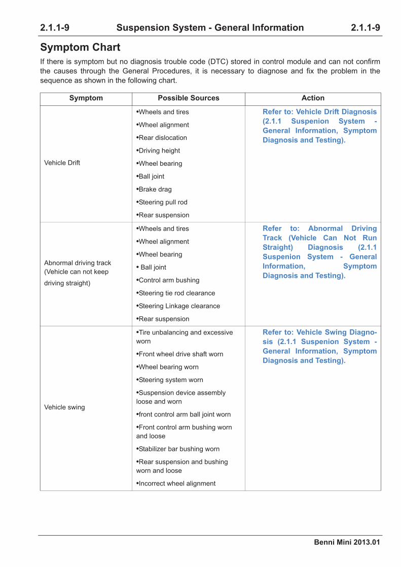
Symptom Chart
If there is symptom but no diagnosis trouble code (DTC) stored in control module and can not confirm
the causes through the General Procedures, it is necessary to diagnose and fix the problem in the
sequence as shown in the following chart.
Symptom Possible Sources Action
Vehicle Drift
•Wheels and tires
•Wheel alignment
•Rear dislocation
•Driving height
•Wheel bearing
•Ball joint
•Brake drag
•Steering pull rod
•Rear suspension
Refer to: Vehicle Drift Diagnosis
(2.1.1 Suspenion System -
General Information, Symptom
Diagnosis and Testing).
Abnormal driving track
(Vehicle can not keep
driving straight)
•Wheels and tires
•Wheel alignment
•Wheel bearing
• Ball joint
•Control arm bushing
•Steering tie rod clearance
•Steering Linkage clearance
•Rear suspension
Refer to: Abnormal Driving
Track (Vehicle Can Not Run
Straight) Diagnosis (2.1.1
Suspenion System - General
Information, Symptom
Diagnosis and Testing).
Vehicle swing
•Tire unbalancing and excessive
worn
•Front wheel drive shaft worn
•Wheel bearing worn
•Steering system worn
•Suspension device assembly
loose and worn
•front control arm ball joint worn
•Front control arm bushing worn
and loose
•Stabilizer bar bushing worn
•Rear suspension and bushing
worn and loose
•Incorrect wheel alignment
Refer to: Vehicle Swing Diagno-
sis (2.1.1 Suspenion System -
General Information, Symptom
Diagnosis and Testing).

2.1.1-10
Benni Mini 2013.01
2.1.1-10Suspension System - General Information
Vehicle shakes in driving
•Tire unbalance and excessive
worn
•Inspect the tire
Refer to: Tire Wear Inspection
(2.1.4 Wheels and Tires, Gen-
eral Procedures).
•Front wheel drive shaft worn
•Inspect the front wheel drive shaft
Refer to: Drive Shaft Inspection
(2.2.1 Driveline - General Infor-
mation, General Procedures).
•Wheel bearing worn •Replace the wheel bearing
•Steering system worn •Replace the steering system worn part
•Suspension device assembly
loose and worn
•Inspect the suspension device assembly
Refer to: Torque Specifications
(2.1.2 Front Suspension, Specifi-
cations), Torque Specifications
(2.1.3 Rear Suspension, Specifi-
cations).
•Suspension device assembly
bracket loose
•Tighten it according to torque requirement
Refer to: Torque Specifications
(2.1.2 Front Suspension, Specifi-
cations), Torque Specifications
(2.1.3 Rear Suspension, Specifi-
cations).
•Front control arm ball joint worn
•Replace the front arm ball joint
Refer to: Front Control Arm
(2.1.2 Front Suspension,
Removal and Installation).
•Front control arm bushing worn
and loose
•Replace the front suspension control arm
bushing
Refer to: Front Control Arm
(2.1.2 Front Suspension,
Removal and Installation).
•Stabilizer bar bushing worn
•Replace the stablizer bar bushing
Refer to: Front Control Arm
(2.1.2 Front Suspension,
Removal and Installation).
Symptom Possible Sources Action

Benni Mini 2013.01
2.1.1-11 2.1.1-11Suspension System - General Information
Vehicle shakes in driving
•Rear suspension and bushing
worn and loose
•Replace the suspension and bushing if
necessary
Refer to: Rear Axle (2.1.3 Rear
Suspension, Removal and
Installation), Rear Axle Bushing
(2.1.3 Rear suspension,
Removal and Installation).
•Incorrect wheel alignment
•Wheel alignment
Refer to: Wheel Alignment (2.1.1
Suspension System - General
Information, General Proce-
dures).
Steering wheel off center•Wheel alignment
•Steering system components•Steering Wheel Off Center Diagnosis
Excessive noise
•Suspension assembly bracket
loose or worn
•Wheel bearing worn
•Front control arm bushing
•Damper spring
•Tire
•Front control arm ball joint
Refer to: Excessive Noise Diag-
nosis (2.1.1 Suspension System
- General Information, Symptom
Diagnosis and Testing).
Incorrect tire wear
•Tire conversion
•Tire pressure
•Wheel distortion
•Unbalancing tire
•Wheel alignment
•Suspension components
•High speed driving
•Rear dislocation
•Overload
•Poor operation habit
Refer to: Incorrect Tire Wear
Diagnosis (2.1.1 Suspension
System - General Information,
Symptom Diagnosis and
Testing).
Symptom Possible Sources Action

2.1.1-12
Benni Mini 2013.01
2.1.1-12Suspension System - General Information
Heavy steering
•Positive camber angle too large
•Wheel alignment
Refer to: Wheel Alignment (2.1.1
Suspension System - General
Information, General Proce-
dures).
•Incorrect vehicle driving height
(front or rear, up or down)
•Load meets the standard and replace the
standard spring components
•Steering Linkage or steering tie
bar worn
•Replace the steering system worn compo-
nents
•Front suspension front control arm
ball joint worn
•Replace front control arm ball joint
Refer to: Front Control Arm
(2.1.2 Front Suspension,
Removal and Installation).
•Tire worn or unbalancing
•Inspect the tires
Refer to: Tire Wear Inspection
(2.1.4 Wheels and Tires, Gen-
eral Procedures).
•Insufficient power steering force
•Inspect the oil pressure and supplement
of power steering system. Inspect power
steering system and replace worn compo-
nents.
Vehicle swag
•Front stabilizer bar or bearing
worn (if equipped)
•Replace the front stabilizer linkage or
bushing
Refer to: Front Control Arm
(2.1.2 Front Suspension,
Removal and Installation).
•Front control arm bushing loose
and worn
•Repair or replace front control arm bush-
ing
Refer to: Front Control Arm
(2.1.2 Front Suspension,
Removal and Installation).
•Suspension assembly loose or
worn
•Inspect the suspension assembly and
replace the worn components
Vehicle lean
•Front and rear damper spring
becomes soft and damaged
•Inspect the damper spring and replace it if
necessary
Refer to: Front Strut Assembly
Disassembly and Assembly
(2.1.2 Front Suspension,
Removal and Installation), Rear
Shock Absorber Assembly
(2.1.3 Rear suspension,
Removal and Installation).
•Tire pressure is improper •Adjust the tire pressure
Symptom Possible Sources Action

Benni Mini 2013.01
2.1.1-13 2.1.1-13Suspension System - General Information
Rough ride
•Front and rear damper springs
become soft
•Inspect the damper spring and replace it if
necessary
Refer to: Front Strut Assembly
Disassembly and Assembly
(2.1.2 Front Suspension,
Removal and Installation), Rear
Shock Absorber Assembly
(2.1.3 Rear suspension,
Removal and Installation).
•Front or rear suspension assem-
bly worn
•Replace the suspension assembly worn
components
Unstable direction
•Tire is unbalancing, damaged or
with too large runout
•Inspect the tires
Refer to: Tire Wear Inspection
(2.1.4 Wheels and Tires, Gen-
eral Procedures).
•Toe-in out of specification
•Wheel alignment
Refer to: Wheel Alignment (2.1.1
Suspension System - General
Information, General Proce-
dures).
•Steering system worn•Replace the steering system worn compo-
nents
•Front control arm ball joint dam-
aged
•Replace the front control arm ball joint
Refer to: Front Control Arm
(2.1.2 Front Suspension,
Removal and Installation).
•Front and rear damper springs
become soft
•Inspect the damper spring and replace it if
necessary
Refer to: Front Strut Assembly
Disassembly and Assembly
(2.1.2 Front Suspension,
Removal and Installation), Rear
Shock Absorber Assembly
(2.1.3 Rear suspension,
Removal and Installation).
•Front or rear suspension assem-
bly worn
•Replace the suspension assembly worn
components
•Rear suspension, bushing or bolt
loose or worn
•Replace the rear suspension worn com-
ponents
•Stabilizer bar bushing worn
•Replace the stablizer bar bushing
Refer to: Front Control Arm
(2.1.2 Front Suspension,
Removal and Installation).
Symptom Possible Sources Action

2.1.1-14
Benni Mini 2013.01
2.1.1-14Suspension System - General Information
Vehicle Drift Diagnosis
Steering wheel can not
return normally
•Incorrect wheel alignment
•Wheel alignment
Refer to: Wheel Alignment (2.1.1
Suspension System - General
Information, General Proce-
dures).
•Steering system worn
•Inspect the steering system
Refer to: (2.4.1 Steering System
- General Information, General
Procedures).
•Front suspension control arm ball
joint worn
•Replace the front suspension control arm
ball joint
Refer to: Front Control Arm
(2.1.2 Front Suspension,
Removal and Installation).
Driving vibration
•Tire
•Front wheel bearing
•Rear wheel bearing
•Front hub
•Rear hub
Refer to: Driving Vibration Diag-
nosis (2.1.1 Suspension System
- General Information, Symptom
Diagnosis and Testing).
Test Conditions Details/Results/Actions
1.Inspect the left and right drift
WARNING: In order to avoid the personal injury caused by out of control operation, road
test should be taken by two persons together to keep safe driving.
CAUTION: When estimating the vehicle, the following conditions must be met.
A.Drive the vehicle on flat road at the speed of 88 km/
h.
B.Make sure there is no crosswind and strong wind in
driving.
C.Drive back and forth at least for 2 times.
D.If the vehicle deviating value is 12 ft within 7
seconds, it indicates vehicle drifts.
Does vehicle drift?
Y
Go to step 2.
N
Adjust the steering wheel to straight positon.
Symptom Possible Sources Action

Benni Mini 2013.01
2.1.1-15 2.1.1-15Suspension System - General Information
2. Inspect the tire
A.Inspect whether all the wheels and tires type are the
same.
B. Inspect whether all the tire worn levels are near.
C.Inspect whether the tire bubbles or cracks.
D.Inspect the tire pressure.
Whether the tire inspection is normal?
Y
Go to step 3.
N
Adjust or replace the tire.
3. Inspect the influence of tire to symptom
A.Swap the front suspension tires.
B.Install 4 tires in good state if necessary.
Does the vehicle drift?
Y
Go to step 4.
N
Replace the tire.
4.Inspect the left and right wheel tread
A.Inspect the left and right wheel tread.
Whether the wheel tread at both sides are the
same?
Y
Go to step 5.
N
Cavibrate the left and right wheel tread.
5.Inspect the steering linkage
A.Lift the vehicle.
Refer to: Lifting (1.1.3 Traction and Lifting,
Description and Operation).
B.Inspect whether the steering linkage is excessively
worn.
Whether the steering linkage is excessively worn?
Y
Replace or repair the damaged components.
N
Go to step 6.
Test Conditions Details/Results/Actions

2.1.1-16
Benni Mini 2013.01
2.1.1-16Suspension System - General Information
6.Inspect the driving height
A.Inspect the driving height.
Whether the driving height is normal?
Y
Go to step 7.
N
Repair the fault due to inconsistent driving height.
7.Inspect the wheel alignment
A.Inspect the wheel alignment.
Whether the steering wheel is in central positon and
whether the wheel alignment data is in the specifi-
cation?
Y
Go to step 8.
N
If necessary, carry out the wheel alignment.
8.Inspect the brake drag
A.Lift the vehicle.
Refer to: Lifting (1.1.3 Traction and Lifting,
Description and Operation).
B.Inspect whether the wheel has brake lag.
Whether the wheel has brake lag?
Y
Repair the brake drag symptom.
Refer to: Brake Drag (2.3.1 Brake System -
General Information, Symptom Diagnosis
and Testing).
N
Go to step 9.
Test Conditions Details/Results/Actions

Benni Mini 2013.01
2.1.1-17 2.1.1-17Suspension System - General Information
Abnormal Driving Track Diagnosis (Vehicle Can Not Run Straight)
9.Inspect the rear suspension
A.Inspect the rear suspension alignment parameter.
Whether the rear suspension alignment is normal?
Y
Inspect the suspension components wear. Replace
or repair the damaged components if necessary.
Refer to: Front Strut Assembly Disassem-
bly and Assembly (2.1.2 Front Suspen-
sion, Removal and Installation), Rear
Shock Absorber Assembly (2.1.3 Rear
suspension, Removal and Installation).
N
Adjust or repair the rear suspension incorrect align-
ment.
Test Conditions Details/Results/Actions
WARNING: In order to avoid the personal injury caused by out of control operation, road
test should be taken by two persons together to keep safe. Be sure to keep the proper
control of steering wheel.
1.Inspect the tire
A.Inspect whether all the wheels and tires type are the
same.
B. Inspect whether all the tire worn levels are near.
C.Inspect whether the tire bubbles or cracks.
D.Inspect the tire pressure.
Whether the tire inspection is normal?
Y
Go to step 2.
N
Adjust or replace the tire.
2. Inspect the influence of tire to symptom
A.Swap the front suspension tires.
B.Install 4 tires in good state if necessary.
Does vehicle drift?
Y
Go to step 3.
N
Replace the tire.
Test Conditions Details/Results/Actions

2.1.1-18
Benni Mini 2013.01
2.1.1-18Suspension System - General Information
3.Inspect the front control arm bushing
A.Inspect whether the front control arm bushing
cracks, looses or moves.
Whether the front control arm inspection is normal?
Y
Go to step 4.
N
Replace the front control arm bushing.
Refer to: Front Control Arm (2.1.2 Front
Suspension, Removal and Installation).
4.Inspect the steering linkage
A.Lift the vehicle.
Refer to: Lifting (1.1.3 Traction and Lifting,
Description and Operation).
B.Inspect whether the steering linkage is excessively
worn.
Whether the steering linkage is excessively worn?
Y
Replace or repair the damaged components.
N
Go to step 5.
5.Inspect the wheel alignment
A.Inspect the wheel alignment.
Whether the steering wheel is in central positon and
whether the wheel alignment data is in the specifi-
cation?
Y
Go to step 6.
N
If necessary, carry out the wheel alignment.
Test Conditions Details/Results/Actions
Benni Mini 2013.01
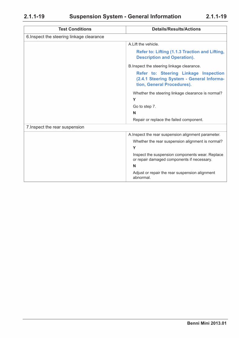
2.1.1-19 2.1.1-19Suspension System - General Information
6.Inspect the steering linkage clearance
A.Lift the vehicle.
Refer to: Lifting (1.1.3 Traction and Lifting,
Description and Operation).
B.Inspect the steering linkage clearance.
Refer to: Steering Linkage Inspection
(2.4.1 Steering System - General Informa-
tion, General Procedures).
Whether the steering linkage clearance is normal?
Y
Go to step 7.
N
Repair or replace the failed component.
7.Inspect the rear suspension
A.Inspect the rear suspension alignment parameter.
Whether the rear suspension alignment is normal?
Y
Inspect the suspension components wear. Replace
or repair damaged components if necessary.
N
Adjust or repair the rear suspension alignment
abnormal.
Test Conditions Details/Results/Actions

2.1.1-20
Benni Mini 2013.01
2.1.1-20Suspension System - General Information
Vehicle Swing Diagnosis
Test Conditions Details/Results/Actions
WARNING: In order to avoid the personal injury caused by out of control operation, road
test should be taken by two persons together to keep safe. Be sure to keep the proper
control of steering wheel.
1. Inspect the tire
A.Inspect whether all the wheels and tires type are the
same.
B. Inspect whether all the tire worn levels are near.
C.Inspect whether the tire bubbles or cracks.
D.Inspect the tire pressure.
Whether the tire inspection is normal?
Y
Go to step 2.
N
Adjust or replace the tire.
2. Inspect the influence of tire to symptom
A.Swap the front suspension tires.
B.Install 4 tires in good state if necessary.
Does vehicle drift?
Y
Go to step 3.
N
Replace the tire.
3.Inspect the front control arm bushing
A.Inspect whether the front control arm bushing
cracks, looses or moves.
Whether the front control arm inspection is normal?
Y
Go to step 4.
N
Replace the front control arm bushing.
Refer to: Front Control Arm (2.1.2 Front
Suspension, Removal and Installation).

Benni Mini 2013.01
2.1.1-21 2.1.1-21Suspension System - General Information
4.Inspect the wheel bearing
A.Lift the vehicle.
Refer to: Lifting (1.1.3 Traction and Lifting,
Description and Operation).
B.Inspect the wheel bearing.
Refer to: Wheel Bearing Inspection (2.1.1
Suspension System - General Informa-
tion, General Procedures).
Whether the wheel bearing is normal?
Y
Go to step 5.
N
Replace the wheel bearing.
5.Inspect the stabilizer bar
A.Inspect whether the stablizier bushing cracks,
looses or lacks.
B.Inspect whether the stabilizer bar is damaged.
Whether the stabilizer bar inspection is normal?
Y
Go to step 6.
N
Repair or replace the stabilizer bar and bushing.
6.Inspect the wheel alignment
A.Inspect the wheel alignment.
Whether the steering wheel is in central positon and
whether the wheel alignment data is in the specifi-
cation?
Y
Go to step 7.
N
If necessary, carry out the wheel alignment.
Test Conditions Details/Results/Actions

2.1.1-22
Benni Mini 2013.01
2.1.1-22Suspension System - General Information
Steering Wheel Off Center Diagnosis
7.Inspect the steering linkage clearance
A.Lift the vehicle.
Refer to: Lifting (1.1.3 Traction and Lifting,
Description and Operation).
B.Inspect the steering linkage clearance.
Refer to: Steering Linkage Inspection
(2.4.1 Steering System - General Informa-
tion, General Procedures).
Whether the steering linkage clearance is normal?
Y
Go to step 8.
N
Repair or replace the failed component.
8.Inspect the rear suspension
A.Inspect the rear suspension alignment parameter.
Whether the rear suspension alignment is normal?
Y
Inspect the suspension components wear. Replace
or repair damaged components if necessary.
N
Adjust or repair the rear suspension alignment
abnormal.
Test Conditions Details/Results/Actions
1.Inspect the steering components
A.Lift the vehicle.
Refer to: Lifting (1.1.3 Traction and Lifting,
Description and Operation).
B.Inspect whether the steering components are
excessively worn?
Whether the steering components are excessively
worn?
Y
Replace or repair the worn components.
N
Go to step 2.
Test Conditions Details/Results/Actions

Benni Mini 2013.01
2.1.1-23 2.1.1-23Suspension System - General Information
Abnormal Driving Track Diagnosis
2.Inspect the wheel alignment
A.Inspect the wheel alignment.
Whether the steering wheel is in central positon and
whether the wheel alignment data is in the specifi-
cation?
Y
Refer to: Abnormal Driving Track Diagno-
sis (2.1.1 Suspension System - General
Information, Symptom Diagnosis and
Testing).
N
Carry out the wheel alignment.
Test Conditions Details/Results/Actions
1.Inspect the front caster angle
A.Inspect the front caster angle.
Whether the front caster angle is within the speci-
fied range?
Y
Go to step 2.
N
Inspect the wear of the suspension components. If
necessary, replace or repair the worn components.
2.Inspect the rear suspension
A.Measure the left and right wheel tread of vehicle.
B.Compare the measured values.
Whether the data are the same?
Y
Carry out the four-wheel alignment.
N
Inspect the wear of the rear suspension compo-
nents. If necessary, replace or repair the worn com-
ponents.
Refer to: (2.1.3 Rear Suspension,
Removal and Installation).
Test Conditions Details/Results/Actions

2.1.1-24
Benni Mini 2013.01
2.1.1-24Suspension System - General Information
Excessive Noise Diagnosis
Test Conditions Details/Results/Actions
1.Inspect the suspension
A.Lift the vehicle.
Refer to: Lifting (1.1.3 Traction and Lifting,
Description and Operation).
B.Inspect the mounting bolts of the suspension
components.
Whether the bolts loose or crack?
Y
Tighten or replace the bolts.
N
Go to step 2.
2. Inspect the damper spring
A.Inspect whether the damper spring is damaged.
Whether the damper spring is damaged?
Y
Replace the damper spring.
N
Go to step 3.
3.Inspect the front control arm
A.Inspect whether the front control arm bushing is
excessively worn or damaged.
whether the front control arm bushing is worn?
Y
Replace the front control arm bushing.
Refer to: Front Control Arm (2.1.2 Front
Suspension, Removal and Installation).
N
Go to step 4.
Benni Mini 2013.01
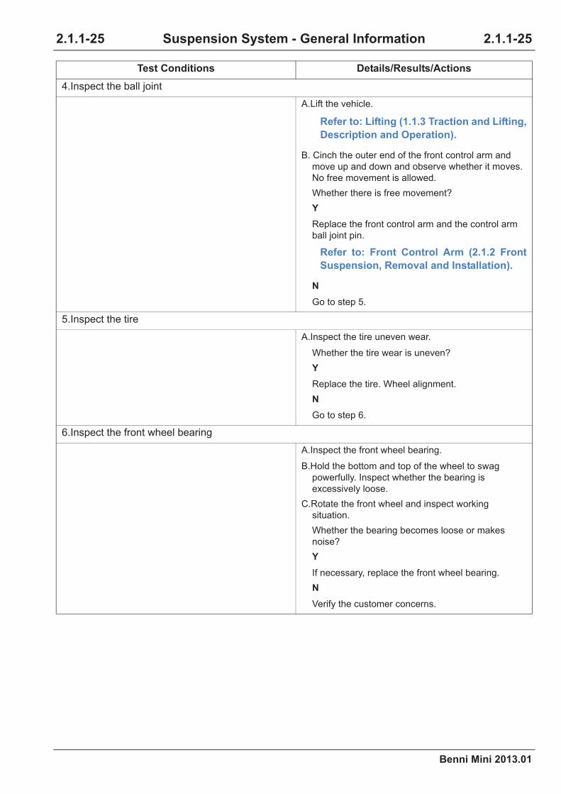
2.1.1-25 2.1.1-25Suspension System - General Information
4.Inspect the ball joint
A.Lift the vehicle.
Refer to: Lifting (1.1.3 Traction and Lifting,
Description and Operation).
B. Cinch the outer end of the front control arm and
move up and down and observe whether it moves.
No free movement is allowed.
Whether there is free movement?
Y
Replace the front control arm and the control arm
ball joint pin.
Refer to: Front Control Arm (2.1.2 Front
Suspension, Removal and Installation).
N
Go to step 5.
5.Inspect the tire
A.Inspect the tire uneven wear.
Whether the tire wear is uneven?
Y
Replace the tire. Wheel alignment.
N
Go to step 6.
6.Inspect the front wheel bearing
A.Inspect the front wheel bearing.
B.Hold the bottom and top of the wheel to swag
powerfully. Inspect whether the bearing is
excessively loose.
C.Rotate the front wheel and inspect working
situation.
Whether the bearing becomes loose or makes
noise?
Y
If necessary, replace the front wheel bearing.
N
Verify the customer concerns.
Test Conditions Details/Results/Actions

2.1.1-26
Benni Mini 2013.01
2.1.1-26Suspension System - General Information
Vibration Diagnosis
Test Conditions Details/Results/Actions
1.Inspect the tire
A.Lift the vehicle.
Refer to: Lifting (1.1.3 Traction and Lifting,
Description and Operation).
B.Inspect whether the tire is damaged or excessively
worn.
Whether the tire is damaged or worn?
Y
Replace the tire.
N
Go to step 2.
2. Inspect the front wheel bearing
A.Inspect the front wheel bearing.
B.Hold the bottom and top of the wheel to swag
powerfully. Inspect whether the bearing is
excessively loose.
C.Rotate the front wheel and inspect working
situation.
Whether the bearing becomes loose or makes
noise?
Y
Go to step 3.
N
Go to step 4.
3.Measure the front bearing axial clearance
A.Remove the wheel, brake caliper and brake disc.
B.Install the dial indicator gauge with mounting
bracket and close to the front wheel hub.
C.Pull and push the wheel hub along axial direction
and inspect the axial clearance of wheel hub and
front wheel bearing.
Whether the axial clearance of the front wheel bear-
ing is in the specification?
Y
Inspect the ball joint. Go to step 4.
N
Replace the wheel hub and bearig assembly.
Benni Mini 2013.01
2.1.1-27 2.1.1-27Suspension System - General Information
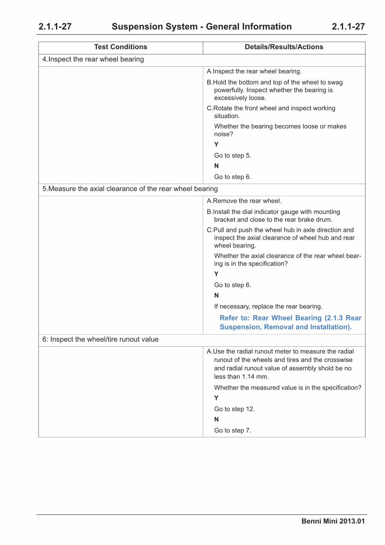
4.Inspect the rear wheel bearing
A.Inspect the rear wheel bearing.
B.Hold the bottom and top of the wheel to swag
powerfully. Inspect whether the bearing is
excessively loose.
C.Rotate the front wheel and inspect working
situation.
Whether the bearing becomes loose or makes
noise?
Y
Go to step 5.
N
Go to step 6.
5.Measure the axial clearance of the rear wheel bearing
A.Remove the rear wheel.
B.Install the dial indicator gauge with mounting
bracket and close to the rear brake drum.
C.Pull and push the wheel hub in axle direction and
inspect the axial clearance of wheel hub and rear
wheel bearing.
Whether the axial clearance of the rear wheel bear-
ing is in the specification?
Y
Go to step 6.
N
If necessary, replace the rear bearing.
Refer to: Rear Wheel Bearing (2.1.3 Rear
Suspension, Removal and Installation).
6: Inspect the wheel/tire runout value
A.Use the radial runout meter to measure the radial
runout of the wheels and tires and the crosswise
and radial runout value of assembly shold be no
less than 1.14 mm.
Whether the measured value is in the specification?
Y
Go to step 12.
N
Go to step 7.
Test Conditions Details/Results/Actions

2.1.1-28
Benni Mini 2013.01
2.1.1-28Suspension System - General Information
7.Measuring the wheel/tire runout value
A.Measure the wheel with over 1.14 mm radial and
crosswise runout. Mark the positons of tire bolts
and relative bolt holes before removing wheel.
Remove wheel and install it on the tire balance
machine to measure runout value. The radial and
crosswise runout of the wheels and tires must be
less than 1.14 mm.
Whether the measuring value is in the specifica-
tion?
Y
Go to step 10.
N
Go to step 8.
8.Match the mounting position
A.Mark the highest runout position of tire and wheel.
Exhaust the air in tire and rotate for 180°. Charge
the tire and mesure its runout value.
Whether the runout positon of tire and wheel is
coincident?
Y
Carry out the tire dynamic balance.
N
If the twice runout top value is out of 101.6 mm,
replace the tire. If the value is in 101.6 mm,
Go to step 9.
9.Measure the wheel runout
A.Remove the wheel cover tyre and install it on the tire
balance machine. Measure the runout of the wheel
inner/outer edge. The runout of crosswise and
radial should be less than 1.14 mm.
Whether the runout is normal?
Y
Go to step 10.
N
Replace the wheel. Inspect the runout of new
wheel. If the runout of new wheel is in regualted
range. Search and mark the lowest point of runout.
Installing the tire and make the highest runout point
and lowest runout point match. Balance the wheel.
Test Conditions Details/Results/Actions

Benni Mini 2013.01
2.1.1-29 2.1.1-29Suspension System - General Information
10.Inspect the radial runout of rear wheel hub and wheel bolt
A.Measure the hub flange runout (beyond 0.254 mm),
and the wheel bolt circle runout (beyond 0.08 mm).
Whether the measuring value is in the specifica-
tion?
Y
Go to step 11.
N
Replace the rear wheel hub.
Refer to: Rear Wheel Bearing (2.1.3 Rear
Suspension, Removal and Installation).
11.Inspect the circle runout of front wheel hub and wheel bolt
A. Remove the front wheels.
B.Remove the brake disc.
C.Measure the radial runout of wheel bolt circule
(beyond 0.06 mm).
Whether the measuring value is in the specifica-
tion?
Y
Inspect the runout of brake disc.
Refer to: Brake Disc Runout Inspection
(2.3.1 Brake System - General Informa-
tion, General Procedures).
N
Replace the wheel hub.
Refer to: Rear Wheel Bearing (2.1.3 Rear
Suspension, Removal and Installation).
12.Balance wheel
A.Balance the wheel. Road test.
Whethter the vehicle vibrates?
Y
Repair.
Refer to: (1.1.5 Noise, Vibration and
Harshness).
N
Confirm the repair.
Test Conditions Details/Results/Actions

2.1.1-30
Benni Mini 2013.01
2.1.1-30Suspension System - General Information
Incorrect Tire Wear Diagnosis
Test Conditions Details/Results/Actions
1. Inspect the tire wear
A.Lift the vehicle.
Refer to: Lifting (1.1.3 Traction and Lifting,
Description and Operation).
B.Inspect the tire wear.
Whether the two front wheels are excessively
worn?
Y
Swap the wheel and replace them if necessary.
N
Go to step 2.
2. Inspect the tire
A.Inspect the tire pressure and type.
Whether the tire pressure is normal or tire type are
the same?
Y
Go to step 3.
N
Replace the tire in different type and adjsut the tire
pressure.
Refer to: General Specifications (2.1.4
Wheels and Tires, Specifications).
3.Inspect the wheel
A.Inspect whether the wheels are twisted.
B.Inspect the wheel runout.
Refer to: Wheel Runout Inspection (2.1.4
Wheels and Tires, General Procedures).
Is the runout nromal?
Y
Go to step 4.
N
Adjust or replace the wheel.
Benni Mini 2013.01
2.1.1-31 2.1.1-31Suspension System - General Information
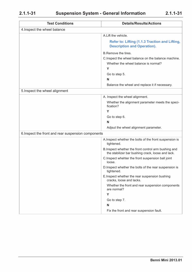
4.Inspect the wheel balance
A.Lift the vehicle.
Refer to: Lifting (1.1.3 Traction and Lifting,
Description and Operation).
B.Remove the tires.
C.Inspect the wheel balance on the balance machine.
Whether the wheel balance is normal?
Y
Go to step 5.
N
Balance the wheel and replace it if necessary.
5.Inspect the wheel alignment
A. Inspect the wheel alignment.
Whether the alignment parameter meets the speci-
fication?
Y
Go to step 6.
N
Adjsut the wheel alignment parameter.
6.Inspect the front and rear suspension components
A.Inspect whether the bolts of the front suspension is
tightened.
B.Inspect whether the front control arm bushing and
the stabilizer bar bushing crack, loose and lack.
C.Inspect whehter the front suspension ball joint
loose.
D.Inspect whether the bolts of the rear suspension is
tightened.
E.Inspect whether the rear suspension bushing
cracks, loose and lacks.
Whether the front and rear suspension components
are normal?
Y
Go to step 7.
N
Fix the front and rear suspension fault.
Test Conditions Details/Results/Actions

2.1.1-32
Benni Mini 2013.01
2.1.1-32Suspension System - General Information
7.Inspect the rear wheelbase
A.Inspect the wheelbase at both sides of vehicle.
Whether the wheelbase at both sides are the
same?
Y
Check the vehicle load state and drive habit, correct
overload and incorrect drive habit.
N
Cavibrate the left and right wheel tread.
Test Conditions Details/Results/Actions
Benni Mini 2013.01
2.1.2-1 2.1.2-1Front Suspension
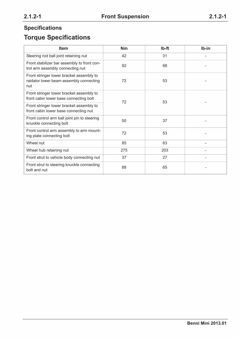
Specifications
Torque Specifications
Item Nm lb-ft lb-in
Steering rod ball joint retaining nut 42 31 -
Front stabilizer bar assembly to front con-
trol arm assembly connecting nut92 68 -
Front stringer lower bracket assembly to
raidator lower beam assembly connecting
nut
72 53 -
Front stringer lower bracket assembly to
front cabin lower base connecting bolt72 53 -
Front stringer lower bracket assembly to
front cabin lower base connecting nut
Front control arm ball joint pin to steering
knuckle connecting bolt50 37 -
Front control arm assembly to arm mount-
ing plate connecting bolt72 53 -
Wheel nut 85 63 -
Wheel hub retaining nut 275 203 -
Front strut to vehicle body connecting nut 37 27 -
Front strut to steering knuckle connecting
bolt and nut88 65 -
2.1.2 Front Suspension

2.1.2-2
Benni Mini 2013.01
2.1.2-2Front Suspension
Description and Operation
System Overview
Front suspension is consisted of two front strut assemblies (including shock damping spring), front con-
trol arm assembly and stabilizer bar assembly.
Front control arm is welded by pressing the steel plate. Every piece is connected with bolt and control
arm mounting plate. The end of stablizier bar cross it and tighten with bolt.
Front control arm is connected with steering knuckle by ball joint.
Wheel steering kuncle is connected with suspension assembly and steering rod ball joint.
Front suspension is supported on upper mounting place with the rubber bushing over the top seat of
strut. Coil spring is mounted between two spring seats on suspension. Cylinder bar has a dust boot to
prevent from dirt and water. A cushion is mounted to pretect suspension in completed pressing state.
Location View
Front Suspension Assembly View
3
2
1
5
6
4
A2102001

Benni Mini 2013.01
2.1.2-3 2.1.2-3Front Suspension
Item Description Item Description
1 Front strut assembly 4 Front control arm
2 Front stabilizer bar 5 Halfshaft
3 Coil spring 6Front stabilizer bar mounting bracket
assembly
2.1.2-4
Benni Mini 2013.01
2.1.2-4Front Suspension
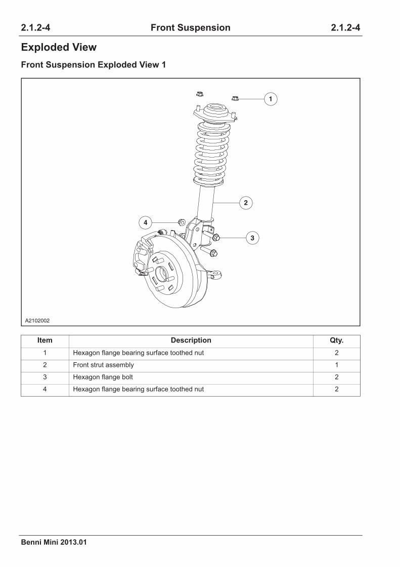
Exploded View
Front Suspension Exploded View 1
Item Description Qty.
1 Hexagon flange bearing surface toothed nut 2
2 Front strut assembly 1
3 Hexagon flange bolt 2
4 Hexagon flange bearing surface toothed nut 2
3
2
1
4
A2102002

Benni Mini 2013.01
2.1.2-5 2.1.2-5Front Suspension
Front Suspension Exploded View 2
Item Description Qty.
1 Hexagon head bolt 1
2 Steering knuckle 1
3 Hexagon flange nut 1
4 Small washer 1
5 Light spring washer 1
6 Hexagon head bolt 1
7 Bushing 1
8 Front control arm assembly 1
9 Clamp 1
10 Dust cover 1
3
2
1
10
9
7
6
8
4
5
A2102003

2.1.2-6
Benni Mini 2013.01
2.1.2-6Front Suspension
Front Suspension Exploded View 3
Item Description Qty.
1 Front control arm assembly 1
2 Front control arm retaining rubber bush 2
3 Hexagon head bolt and spring washer 4
4 Front control arm mounting bracket assembly (Right) 1
5 Front control arm connecting rubber bush 4
6 Front control arm connecting rubber bush washer 2
7 Hexagon slotted nut 1
8 split pin 2
8
3
1
3
4
6
2
5
5
7
A2102004

Benni Mini 2013.01
2.1.2-7 2.1.2-7Front Suspension
Symptom Diagnosis and Testing
Refer to: Symptom Chart (2.1.1 Suspen-
sion System - General Information, Symp-
tom Diagnosis and Testing).

2.1.2-8
Benni Mini 2013.01
2.1.2-8Front Suspension
Disassembly and Assembly
Strut and Spring Assembly
Disassembly
1. Use the coil damping spring compression tool
to press the coil spring partly.
CAUTION: Be careful to the coil spring in
extremely pressed state to avoid injury.
A2102023

Benni Mini 2013.01
2.1.2-9 2.1.2-9Front Suspension
Assembly
2. Disassemble the front shock absorber and
the coil spring
1. Remove the nuts.
Torque: 54 Nm
2. Remove the flat washer.
3. Remove the spring washer.
4. Remove the inner adapter sleeve assembly.
5. Remove the outer adapter sleeve assembly.
6. Remove the flat washer.
7. Remove the backup washer.
8. Remove the bearing.
9. Remove the fitting seat assembly.
10. Remove the spring washer.
11. Remove the coil spring.
12. Remove the anti-collision cushion.
13. Remove the front shock absorber assembly.
1. To assemble, reverse the disassemble
procedure.
CAUTION: Put spring end on spring seat
correctly.
2. Aligning wheels.
2
4
6
8
10
13
12
9
7
5
3
1
11
A2102024

2.1.2-10
Benni Mini 2013.01
2.1.2-10Front Suspension
Removal and Installation
Front Control Arm
Removal
Installation
1. To install, reverse the removal procedure.
1. Remove the wheel.
Refer to: Wheel and Tire (2.1.4 Wheels and
Tires, Removal and Installation).
2. Lift the vehicle.
Refer to: Lifting (1.1.3 Traction and Lifting,
Description and Operation).
3. Remove the stabilizer bar opening nut.
1. Remove the cotter pin.
2. Remove the stabilizer bar opening nut.
Torque: 92 Nm
4. Remove both sides of the stabilizer bar
rubberbush and the stabilizer bar seat
retaining bolts.
Torque: 72 Nm
5. Detach the front stabilizer bar.
6. Remove the retaining bolt (1) between the
front control arm and the steering knuckle.
Torque: 50 Nm
7. Remove the retaining bolt (2) between the
front control arm and the body bracket.
Torque: 72 Nm
8. Detach the front control arm.
A2102005
1
2
A2102006
Benni Mini 2013.01
2.1.2-11 2.1.2-11Front Suspension
Steering Knuckle
Removal
Special Tool
Ball Joint Puller
CA201-001
1. Remove the wheel.
Refer to: Wheel and Tire (2.1.4 Wheels and
Tires, Removal and Installation).
2. Lift the vehicle.
Refer to: Lifting (1.1.3 Traction and Lifting,
Description and Operation).
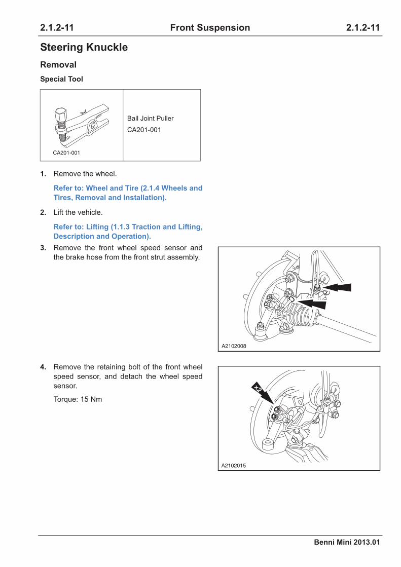
3. Remove the front wheel speed sensor and
the brake hose from the front strut assembly.
4. Remove the retaining bolt of the front wheel
speed sensor, and detach the wheel speed
sensor.
Torque: 15 Nm
CA201-001
A2102008
×2
A2102015

2.1.2-12
Benni Mini 2013.01
2.1.2-12Front Suspension
5. Remove the tie rod ball joint and the stabilizer
bar.
1.Detach the cotter pin and remove the tie rod
ball joint retaining nut.
Torque: 48 Nm
2.Detach the cotter pin and remove the stabi-
lizer bar retaining nut.
Torque: 92 Nm
CAUTION: Use soft cloth to protect the
ball joint to avoid damage.
6. Remove the front stabilizer bar assembly.
1.Remove both sides of the stabilizer bar seat
retaining bolts.
Torque: 72 Nm
2.Detach the front stabilizer bar assembly.
7. Remove the halfshaft retaining nut.
Torque: 275 Nm
8. Detach the front arm ball joint from the
steering knuckle.
1.Remove the retaining nut of the front arm
ball joint.
Torque: 50 Nm
2.Detach the front arm ball joint from the
steering knuckle.
9. Pull out the halfshaft from the steering
knuckle with a puller.
21
A2102010
1
2
A2202020
2
1
A2202021
A2102016
A2102013A2202022

Benni Mini 2013.01
2.1.2-13 2.1.2-13Front Suspension
Installation
1. To install, reverse the removal procedure.
10. Remove the brake caliper.
Refer to: Brake caliper (2.3.3 Front disc
brake, Removal and Installation).
11. Remove the brake disc.
Refer to: Brake Disc(2.3.3 Front disc
brake, Removal and Installation).
12. Remove the front strut assembly and the
steering knuckle bolt and nut.
Torque: 88 Nm
13. Detach the steering knuckle from the front
strut assembly.
A2102014

2.1.2-14
Benni Mini 2013.01
2.1.2-14Front Suspension
Bearing
Removal
1. Remove the wheel.
Refer to: Wheel and Tire (2.1.4 Wheels and
Tires,Removal and Installation).
2. Remove the steering knuckle.
Refer to: Steering Knuckle (2.1.2 Front
Suspension, Removal and Installation).
3. Remove the hub.
CAUTION: Press out the hub using proper
removal tools, and do not damage the
spline in the hub.
4. Remove the snap ring.
5. Remove the bearing.
A2102017
A2102018
A2102019

Benni Mini 2013.01
2.1.2-15 2.1.2-15Front Suspension
Installation
1. Install the bearing.
CAUTION: Install the bearing into the
steering knuckle using proper installation
tools and ensure the force point of the
bearing is the bearing outer ring when
pressing it, otherwise it will damage it.
2. Install the snap ring.
3. Install the hub.
CAUTION: Install the hub into the bearing
using proper installation tools and ensure
the force point of the bearing is the
bearing inner ring when pressing the hub,
otherwise it will damage the bearing. After
installation in place, turn the hub and
there should be no jam.
4. Install the steering knuckle.
Refer to: Steering Knuckle (2.1.2 Front
Suspension, Removal and Installation).
5. Install the wheel.
Refer to: Wheel and Tire (2.1.4 Wheels and
Tires,Removal and Installation).
6. Align wheels.
A2102020
A2102021
A2102022

2.1.2-16
Benni Mini 2013.01
2.1.2-16Front Suspension
Front Strut Assembly
Removal
Installation
1. To install, reverse the removal procedure.
1. Remove the wheel.
Refer to: Wheel and Tire (2.1.4 Wheels and
Tires, Removal and Installation).
2. Lift the vehicle.
Refer to: Lifting (1.1.3 Traction and Lifting,
Description and Operation).
3. Remove the front wheel speed sensor and
the brake hose from the front strut assembly.
4. Remove the front strut and the steering
knuckle clevis bolt and nut.
Torque: 88 Nm
5. Detach the steering knuckle from the front
strut.
6. Remove the two retaining nuts on the front
strut and detach the front strut assembly.
Torque: 37 Nm
A2102008
A2102014
A2102007

Benni Mini 2013.01
2.1.3-1 2.1.3-1Rear Suspension
Specifications
Torque Specifications
Item Nm lb-ft lb-in
Rear shock absorber to body connecting
bolt88 65- -
Rear shock absorber to rear axle connect-
ing bolt88 65- -
Brake hose connector 16 12 -
Wheel nut 85 63 -
Wheel shaft retaining bolt 220 162 -
Longitudinal control arm to rear axle con-
necting bolt88 65 -
Longitudinal control arm to body connect-
ing bolt88 65 -
Stabilizer bar to body connecting bolt 45 33 -
Stabilizer bar to rear axle connecting bolt 45 33 -
Rear brake to rear axle assembly con-
necting bolt42 31 -
ABS rear wheel speed sensor head to
rear axle flange9 - 80
Brake hose M10 thread connecting 16 12 -
Brake hose M12 thread connecting 18 13 -
2.1.3 Rear Suspension

2.1.3-2
Benni Mini 2013.01
2.1.3-2Rear Suspension
Description and Operation
System Overview
Rear suspension is twisting beam semi-independent suspension and consisted of coil spring, rear axle,
rear shock absorber, stabilizer bar and longitudinal control arm. The stabilizer bar is installed on the body
and the rear axle by a bushing to prevent the rear axle from transverse motion. The rear shock absorber
is installed between the body and the rear axle to slow down the vertical motion of the body.

Benni Mini 2013.01
2.1.3-3 2.1.3-3Rear Suspension
Location View
Rear Suspension Assembly View
Item Description Item Description
1 Longitudinal control arm 4 Stabilizer bar
2 Rear shock absorber assembly 5 Coil spring
3 Rear axle assembly 6 Rear brake assembly
6
2
1
5
4
3
A2103001
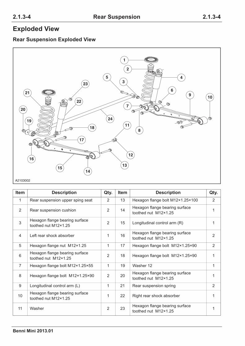
2.1.3-4
Benni Mini 2013.01
2.1.3-4Rear Suspension
Exploded View
Rear Suspension Exploded View
24
Item Description Qty. Item Description Qty.
1 Rear suspension upper sping seat 2 13 Hexagon flange bolt M12×1.25×100 2
2 Rear suspension cushion 2 14Hexagon flange bearing surface
toothed nut M12×1.251
3Hexagon flange bearing surface
toothed nut M12×1.252 15 Longitudinal control arm (R) 1
4 Left rear shock absorber 1 16Hexagon flange bearing surface
toothed nut M12×1.252
5 Hexagon flange nut M12×1.25 1 17 Hexagon flange bolt M12×1.25×90 2
6Hexagon flange bearing surface
toothed nut M12×1.252 18 Hexagon flange bolt M12×1.25×90 1
7 Hexagon flange bolt M12×1.25×55 1 19 Washer 12 1
8 Hexagon flange bolt M12×1.25×90 2 20Hexagon flange bearing surface
toothed nut M12×1.251
9 Longitudinal control arm (L) 1 21 Rear suspension spring 2
10Hexagon flange bearing surface
toothed nut M12×1.251 22 Right rear shock absorber 1
11 Washer 2 23Hexagon flange bearing surface
toothed nut M12×1.251
18
17
4
7
1
2
8
14
16
20
19
109
11
23
22
621
5
3
1513
12
24
A2103002

Benni Mini 2013.01
2.1.3-5 2.1.3-5Rear Suspension
12 Spring washer 2 24 Stabilizer bar 1
Item Description Qty. Item Description Qty.

2.1.3-6
Benni Mini 2013.01
2.1.3-6Rear Suspension
Symptom Diagnosis and Testing
Refer to: Symptom Chart (2.1.1 Suspen-
sion System - General Information, Symp-
tom Diagnosis and Testing).
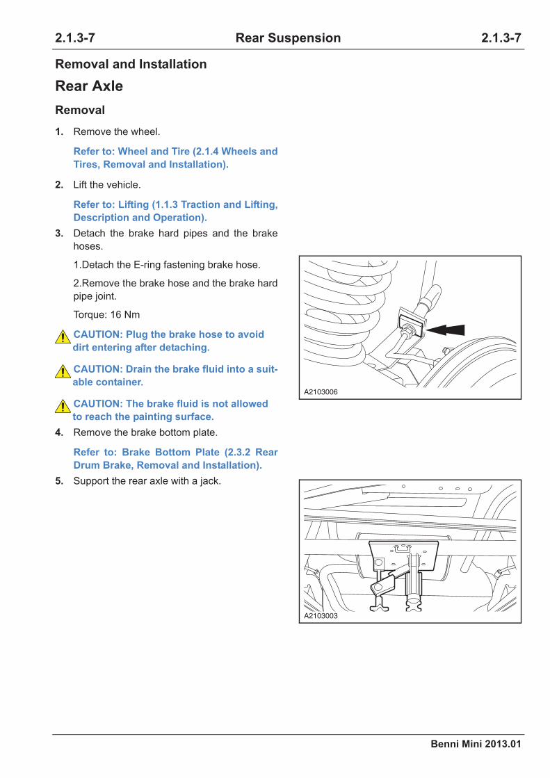
Benni Mini 2013.01
2.1.3-7 2.1.3-7Rear Suspension
Removal and Installation
Rear Axle
Removal
1. Remove the wheel.
Refer to: Wheel and Tire (2.1.4 Wheels and
Tires, Removal and Installation).
2. Lift the vehicle.
Refer to: Lifting (1.1.3 Traction and Lifting,
Description and Operation).
3. Detach the brake hard pipes and the brake
hoses.
1.Detach the E-ring fastening brake hose.
2.Remove the brake hose and the brake hard
pipe joint.
Torque: 16 Nm
CAUTION: Plug the brake hose to avoid
dirt entering after detaching.
CAUTION: Drain the brake fluid into a suit-
able container.
CAUTION: The brake fluid is not allowed
to reach the painting surface.
4. Remove the brake bottom plate.
Refer to: Brake Bottom Plate (2.3.2 Rear
Drum Brake, Removal and Installation).
5. Support the rear axle with a jack.
A2103006
A2103003

2.1.3-8
Benni Mini 2013.01
2.1.3-8Rear Suspension
6. Remove the lower retaining bolts of both rear
shock absorbers.
Torque: 87.5 Nm
7. Remove the stabilizer bar connecting nut to
the rear axle assembly .
Torque: 45 Nm
8. Loosen the trailing arm connecting nut to the
rear axle, but do not detach the connecting
bolt.
Torque: 87.5 Nm
A2103009
A2103012
A2103013

Benni Mini 2013.01
2.1.3-9 2.1.3-9Rear Suspension
Installation
9. Lower the rear axle by adjusting the jack
gradually until the rear coil spring can be
removed.
10. Support the rear axle, appropriately lift the
jack, remove the trailing arm and the rear axle
connecting bolt.
11. Detach the rear axle from the chassis.
CAUTION: Only when the vehicle weight is
beared by wheels, the rear suspension
parts can be tightened finally.
CAUTION: Make the spring end fit the stair
portion of the rear axle spring seat when
installing the coil spring.
CAUTION: Avoid fingers crushed by
spring.
1. To install, reverse the removal procedure.
2. Bleed the brake system.
Refer to: Brake System Bleeding (2.3.1
Brake System - General Information, Gen-
eral Procedures).
3. Adjust the parking brake cable.
Refer to: Parking Brake Cable Adjustment
(2.3.4 Parking Brake and Control, General
Procedures).
A2103011
A2103003

2.1.3-10
Benni Mini 2013.01
2.1.3-10Rear Suspension
Rear Wheel Bearing
Removal
1. Remove the wheel.
Refer to: Wheel and Tire (2.1.4 Wheels and
Tires, Removal and Installation).
2. Lift the vehicle.
Refer to: Lifting (1.1.3 Traction and Lifting,
Description and Operation).
3. Remove the brake drum.
Refer to: Brake Drum (2.3.2 Rear Drum
Brake, Removal and Installation).
4. Remove the grease seal cover.
5. Burst through the rear wheel bearing
retaining nut insurance using proper tools.
A2103015
A2103016
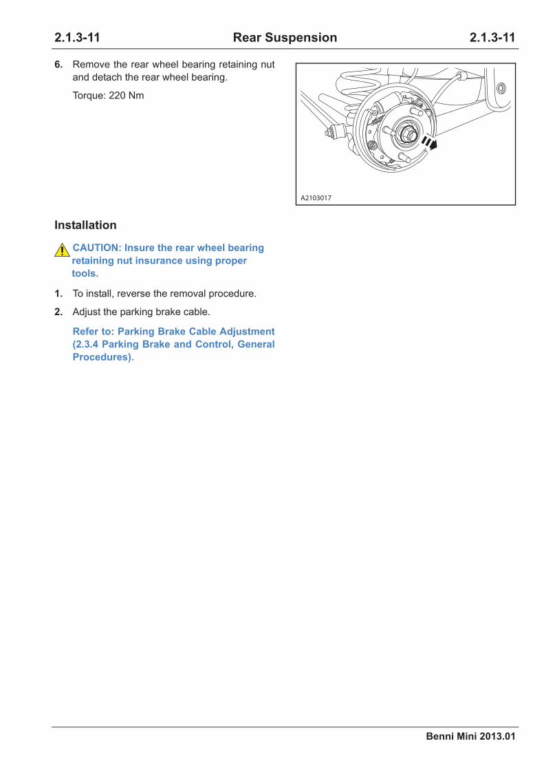
Benni Mini 2013.01
2.1.3-11 2.1.3-11Rear Suspension
Installation
6. Remove the rear wheel bearing retaining nut
and detach the rear wheel bearing.
Torque: 220 Nm
CAUTION: Insure the rear wheel bearing
retaining nut insurance using proper
tools.
1. To install, reverse the removal procedure.
2. Adjust the parking brake cable.
Refer to: Parking Brake Cable Adjustment
(2.3.4 Parking Brake and Control, General
Procedures).
A2103017

2.1.3-12
Benni Mini 2013.01
2.1.3-12Rear Suspension
Rear Shock Absorber Assembly
Removal
Installation
1. To install, reverse the removal procedure.
1. Lift the vehicle.
Refer to: Lifting (1.1.3 Traction and Lifting,
Description and Operation).
2. Support the rear axle with a jack.
3. Remove the lower mounting nut of the rear
shock absorber.
Torque: 88 Nm
A2103003
A2103014

Benni Mini 2013.01
2.1.3-13 2.1.3-13Rear Suspension
Stabilizer Bar
Removal
Installation
1. To install, reverse the removal procedure.
1. Remove the stabilizer bar and the left rear
axle connection.
1.Remove the stabilizer bar left connecting
bolt.
2.Remove the stabilizer bar right connecting
bolt and detach the flat washer.
Torque: 45 Nm
3.Detach the stabilizer bar.
21
A2103023

2.1.3-14
Benni Mini 2013.01
2.1.3-14Rear Suspension
Trailing Arm
Removal
Installation
1. To install, reverse the removal procedure.
1. Lift the vehicle.
Refer to: Lifting (1.1.3 Traction and Lifting,
Description and Operation).
2. Support the rear axle with a jack.
3. Remove the rear shock absorber assembly.
Refer to: Rear Shock Absorber Assembly
(2.1.3 Rear Suspension, Removal and
Installation).
4. Release the trailing arm 2 connecting nuts to
the rear axle , and detach the connecting bolt.
Torque: 87.5 Nm
5. Release the trailing arm connecting nut to the
vehicle body , and detach the connecting bolt.
Torque: 87.5 Nm
A2103003
×2
A2103008
A2103018

Benni Mini 2013.01
2.1.4-1 2.1.4-1Wheels and Tires
Specifications
General Specifications
Torque Specifications
Item Specification
Tire specification
Aluminum wheel 175/60 R13
Steer wheel with decorative
cover155/65 R13
Front tire pressureNon-load 210 kPa
Full load 230 kPa
Rear tire pressureNon-load 230 kPa
Full load 230kPa
Item Nm lb-ft lb-in
Wheel bolt 85 63 -
2.1.4 Wheels and Tires

2.1.4-2
Benni Mini 2013.01
2.1.4-2Wheels and Tires
Description and Operation
System Overview
Tire Identification
The tire type, size, load and speed level are
coded with letters and numbers and printed on
the side wall of tire. Refer to “Tire Identification
Chart” to interpreate code. P155 / 65 R 13 73T is
used as an example. As for all-weather tire, M +
S, M&S or M-S (means mire and snow traction)
are printed on side wall. Overload and lightload
marks of “XL”or “LL” are possibly printed on the
tire side wall. The tire without “XL” or “LL” sign
can be identified as standard load tire.
Tire Identification Chart
Height/width radio = Height(2) ÷ Width(1)
P
Tire type
(available for some
tires)
P - Passenger
car
T - Spare tire
C - Commercial
vehicle
LT - Light truck
155 End face width In mm
65 Height-width ratioEnd face height/
end face width
R Structural typeR - Radial
B - Bias
13 Wheel diameter In inch
73 Load level
Consult the tire
manufacturer for
details
T Speed level
Consult the tire
manufacturer for
details
1
2
A2104001

Benni Mini 2013.01
2.1.4-3 2.1.4-3Wheels and Tires
Exploded View
Item Description Qty. Item Description Qty.
1 Steel wheel cover assembly 1 6 Wheel centre cover 1
2 Combination bolt 1 7 Wheel nut 4
3 Steel wheel 1 8 Aluminium alloy wheel 1
4 Tire 155/65 R13 1 9 Tire 175/60 R13 1
5 Steel wheel balance block 1
2
3
4
6
89
5
7
1
A2104002

2.1.4-4
Benni Mini 2013.01
2.1.4-4Wheels and Tires
General Procedures
WARNING: It is forbidden to install the
tires with different types on the same vehi-
cle except in emergency (temporary use),
such as radial tire, bias tire and bias cord
tire.
WARNING: It is forbidden to start the
engine when replacing tires. Vehicle may
move if the wheels touch the ground.
WARNING: The tire sealant is inflammable.
Remind cutomers not use this kind of
materials.
WARNING: Wear safety goggles and veil in
the maintenance of wheel and tire assem-
bly.
WARNING: After replacing wheel and
wheel bolt becomes loose, tightened them
after driving for 800 km.
WARNING: Make sure to tighten wheel bolt
in regulated mileage, otherwise, the wheel
could leave from vehicle body in driving.
WARNING: Wheel shaft, wheel and tire all
have maximum weight. Overload is forbid-
den.
WARNING: It is forbidden to use wire wool
to grind the wheel. Use abluent to clean
aluminium alloy wheel.
WARNING: Before removing tire valve,
lower tire air pressure first.
Failure to follow above instructions may result in
personal injury.
Inspection and Identification
In order to get the best effect, inspect whether
the wheel pressure and wheel are normal. If
these evidences appear, it indicates that
dynamic balancing, exchange or front wheel
alignment is required. Regularly inspect whether
there is score, scrape, wear, sparging and any-
thing inserted in tire tread. If the temperature of
wheel rises rapidly or minces spread on rough
road surface, inspect the wheel more frequently.
The tire wear indicator at the bottom of tread can
be regarded as direct inspection of tire situation.
When tire wear indicator exposes, replace the
tire.
Tire Wear Diagnosis
When tire wear indicator exposes or tire shoul-
der seriously wears, the tire should be replaced.
Tire shoulder wear is always caused by too large
meridian tire camber angle or wheel toe-in.
Some times, incorrect rear wheel toe-in or dam-
aged standing pillar will cause the serious
“unken” and “ector” wear of undriving wheel.
Serious incorrect rear wheel toe-in will cause
other abnormal wear.
Wheel Runout Inspection
Use dial indicator gauge to measure wheel run-
out capacity on and off the vehicle. Make sure
installation surface is correct. The measurement
can be availiable after tire installation and with-
out tire installation. Measure radial runout and
end face runout in the inner side and outer side
of wheel flange. Fix dial indicator gauge on the
side of wheel and tire assembly, slowly rotate
wheel for a circle and record the read of dial indi-
cator gauge. If runout exceeds the following
specification, and the vibration can not be fixed
after wheel balance, replace the wheel.
Wheel
TypeRadial Runout
End Face
Runout
Steeliness 0.7 mm 0.9 mm
Aluminium 0.5 mm 0.5 mm
33
21
A2104003

Benni Mini 2013.01
2.1.4-5 2.1.4-5Wheels and Tires
Initial Inspection Before Wheel Alignment
Inspection Operation
Inspect whether tire type and wheel type are in
accordance.Inspect tire and wheel, replace them if necessary.
Inspect whether tire pressure and tire tread
wear are normal.
Charge tire with correct pressure. Replace wheel if neces-
sary.
Inspect whether wheel bearing looses.Tighten axle nut to the correct specification. Replace column
wheel bearing if necessary.
Inspect whether ball joint and steering tie rod
loose.Tighten ball joint and steering tie rod.
Inspect wheel and tire runout. Measure and calibrate tire runout.
Inspect the vehicle gross height. Calibrate the gross height. Calibrate before adjuting toe-in.
Inspect rear wheelbase. Calibrate rear wheelbase.
Inspect whether rack and small gear loose. Tighten mounting bracket of rack and small gear.
Inspect whether column operation is incorrect. Replace column assembly.
Inspect whether control arm looses.Tighten control arm joint bolt. Replace control arm bushing if
necessary.

2.1.4-6
Benni Mini 2013.01
2.1.4-6Wheels and Tires
Tire Wear Inspection
Symptom Cause
•Tire shoulder rapid wear•Insufficient inflation tire
•Not swap the tires
•Central rapid wear •Exessive inflation tire
•Not swap the tires
•Tire tread cracks
•Insufficient inflation tire
•Too high speed
A2104004A2104005
A2104006 A2104007
A2104008
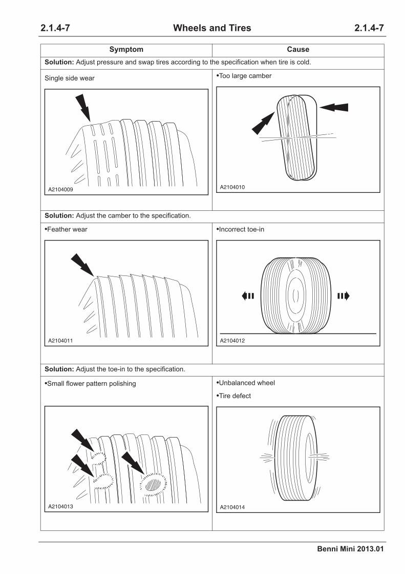
Benni Mini 2013.01
2.1.4-7 2.1.4-7Wheels and Tires
Solution: Adjust pressure and swap tires according to the specification when tire is cold.
Single side wear •Too large camber
Solution: Adjust the camber to the specification.
•Feather wear •Incorrect toe-in
Solution: Adjust the toe-in to the specification.
•Small flower pattern polishing •Unbalanced wheel
•Tire defect
Symptom Cause
A2104009A2104010
A2104011 A2104012
A2104013 A2104014

2.1.4-8
Benni Mini 2013.01
2.1.4-8Wheels and Tires
Solution: Tire dynamic balancing.
•Large wear of edge flower pattern
•No swap tires
•Suspension worn and needs adjustment
Solution: Swap tires.
Solution: Adjust or repair suspension.
Symptom Cause
A2104015

Benni Mini 2013.01
2.1.4-9 2.1.4-9Wheels and Tires
Symptom Diagnosis and Testing
Special Equipments
Inspection and Verification
Inspect whether the tire pressure and wheel are
abnormal to ensure the maximum efficiency of
the tire in running. Such phenomena prove that
the tire shall be adjusted on its dynamic balance,
wheel exchange or front wheel alignment. It is
necessary to inspect whether the tire has cuts,
scratches, blisters and inserts regularly. If the
tire is usually running on rough road surface with
obstructions or easily heated up within a short
period time, more frequent inspections shall be
conducted.
A tire indicator line is marked at the bottom of
the tire to inspect the tire more visually. The tire
shall be replaced when the tire wear indicator
line is exposed.
Tire Wear Diagnosis
When tire wear indicator exposes or tire shoul-
der seriously wears, the tire should be replaced.
Tire shoulder wear is always caused by too large
meridian tire camber angle or wheel toe-in.
Some times, incorrect rear wheel toe-in or dam-
aged standing pillar will cause the serious
“unken” and “ector” wear of undriving wheel.
Serious incorrect rear wheel toe-in will cause
other abnormal wear.
Road Test
The tire vibration diagnosis starts from road test.
Communicate with the customer (if possible) for
more information about vibration sources.
Road test should be carried out on flat ground.
Pay attention to and record the following items if
vibration appears.
• The vehicle speed when vibration
appears.
• The vibration types in all speed range.
• Mechanical or items can be heard.
What influence happens to the vibration when
the following conditions change:
• Engine torque
• Vehicle speed
• Engine speed
Vibration Type:
• Sensibility: Torque sensibility, vehicle
speed sensibility, engine speed
sensibility.
The following explanations are useful to differen-
tiate the vibration sources.
1. Torque sensitivity
It means the situations will become better
or worse due to acceleration, deceleration,
coasting, constant speed and engine torque.
2. Vehicle speed sensitivity
It means the vibration always appears at the
same vehicle speed and will not be
influenced by engine torque, engine speed or
gear position.
3. Engine speed sensitivity
It means the vibration appears at the speed in
different gears. This can be tested by
increasing or decreasing engine speed in
natural position or tested when the gear box
stalls. If the symptom is caused by engine
speed, it may have nothing to do with the tire.
If tire makes sob sound in road test but no
vibration and shake, the noise may be
caused by the contact between tire and road
surface.
Large noise indicates a flat tire or something
soft contacting the road surface. The sob
sound of tire will be regarded as axle noise by
mistake. The tire sob could continously sound
at a certain vehicle speed.
Four-wheel alignment device
Tire balance machine
Tire replacer

2.1.4-10
Benni Mini 2013.01
2.1.4-10Wheels and Tires
Symptom Chart
If there is symptom but no diagnosis trouble code (DTC) is stored in control module and can not con-
firm symptom reasons in the regular inspect, it is necessary to fix the fault in the order listed in the fol-
lowing chart.
Symptom Possible Sources Action
Tire wear diagnosis
•Tire swap
•Tire pressure
•Wheel distortion
•Tire unlalanced
•Wheel alignment
•Suspension components
•High speed driving
•Rear axle
•Overload
• Incorrect operation habit
Refer to: Incorrect Tire Wear
Diagnosis (2.1.1 Suspension
System - General Informa-
tion, Symptom Diagnosis and
Testing).

Benni Mini 2013.01
2.1.4-11 2.1.4-11Wheels and Tires
Vibration caused by wheel
and tire
•Tire pressure too high •Adjust tire pressure.
•Unbalancing wheel or tire •Balance wheel and tire assembly.
•Uneven wear of tire•Install new tire if necessary to avoid
vibration.
•Unbalancing brake disc
•Inspect whether there is soil or pieces
on brake disc. If brake disc is not dam-
aged or there is no pieces, brake disc
may be covered by a lot of dirts.
•Water in tire •Drain water.
•Wheel distorted
•Install a new wheel. Repairing the
wheel could cause crack and reduce
the strength of wheel.
•Correct tire edge assembly
•Rotate the wheel on the vehicle.
Inspect the joint of tire and wheel. If
the parts swing in rotation, it means
that the wheel and tire are not assem-
bled very well. Remove tire and clean
the joint of wheel and tire.
•Wheel or tire radial runout too large
•Measure radial runout of tire and wheel
with dial indicator gauge. If the radial
runout is out of specification, inspect
the radial runout of wheel bolt.
Replace the wheel bolts if the runout is
out of specificiation.
•Wheel bolt looses or damaged or
wheel bolt hole enlarges.
•Tighten or replace components if nec-
essary.
•Foreign materials between mounting
surfaces of the wheel and wheel hub•Clean mounting surface.
•Wheel or tire radial runout too large
•Measure radial runout of tire and wheel
with dial indicator gauge. If the radial
runout is out of specification, inspect
the radial runout of wheel bolt.
Replace the wheel bolts if the runout is
out of specificiation.
•Front wheel bearing damaged
•Replace front wheel bearing.
Refer to: Front Wheel Hub
(2.1.4 Wheels and Tires,
Removal and Installation).
Symptom Possible Sources Action

2.1.4-12
Benni Mini 2013.01
2.1.4-12Wheels and Tires
Removal and Installation
Wheels and Tires
Removal
Installation
1. To install, reverse the removal procedure.
1. Loosen the wheel retaining nut in
anticlockwise direction.
2. Lift the vehicle.
Refer to: Lifting (1.1.3 Traction and Lifting,
Description and Operation).
3. Remove the wheels and tires.
Torque: 85 Nm
CAUTION: Do not heat to loosen the
blocked wheel nut. Heating may damage
wheel and wheel hub.
CAUTION: Clean the rusty stain and dust
on wheel, wheel hub and installation sur-
face of brake disc. All of these may loosen
wheel bolt and wheel in driving. Failure to
follow the instructions may cause per-
sonal injury.
×4
A2104016

Benni Mini 2013.01
Driveline System
2.2 Driveline System
2012 Benni Mini
2.2.1Driverline System - General Information
Description and Operation ............................................................................................................... 2.2.1-1
System Overview...................................................................................................................... 2.2.1-1
General Procedures......................................................................................................................... 2.2.1-2
Driveshaft Inspection ................................................................................................................ 2.2.1-2
Driveshaft Oil Seal Inspection .................................................................................................. 2.2.1-2
Symptom Diagnosis and Testing...................................................................................................... 2.2.1-3
Inspection and Verification........................................................................................................ 2.2.1-3
Symptom Chart......................................................................................................................... 2.2.1-3
Driveshaft Noises ..................................................................................................................... 2.2.1-4
Clunk Noises at Acceleration After Neutral Position Coasting ................................................. 2.2.1-6
Shudder or Vibration During Acceleration ................................................................................ 2.2.1-7
Driveshaft Pullout ..................................................................................................................... 2.2.1-8
Driveshaft Swing....................................................................................................................... 2.2.1-9
Vehicle Shimmy At Low Speed............................................................................................... 2.2.1-10
2.2.2 Driveshaft
Specifications ................................................................................................................................... 2.2.2-1
Material specifications .............................................................................................................. 2.2.2-1
Capacity.................................................................................................................................... 2.2.2-1
Torque Specifications................................................................................................................ 2.2.2-1
Description and Operation ............................................................................................................... 2.2.2-2
System Overview...................................................................................................................... 2.2.2-2
Cautions for Halfshaft ............................................................................................................... 2.2.2-2
Exploded View.......................................................................................................................... 2.2.2-3
Symptom Diagnosis and Testing...................................................................................................... 2.2.2-4
Disassembly and Assembly ............................................................................................................. 2.2.2-5
Inner Constant Velocity (CV) Joint and Rubber Boot ............................................................... 2.2.2-5
Outer Constant Velocity (CV) Joint and Rubber Boot............................................................... 2.2.2-8
Removal and Installation................................................................................................................ 2.2.2-12
Left-Hand Halfshaft................................................................................................................. 2.2.2-12
Right-Hand Halfshaft .............................................................................................................. 2.2.2-14
Table of Contents Pages

Benni Mini 2013.01
Driveline System
2.2.3 Differential
Specifications ...................................................................................................................................2.2.3-1
General Specifications ..............................................................................................................2.2.3-1
Torque Specifications................................................................................................................2.2.3-1
Description and Operation................................................................................................................2.2.3-2
Exploded View ..........................................................................................................................2.2.3-2
Symptom Diagnosis and Testing ......................................................................................................2.2.3-3
Disassembly and Assembly .............................................................................................................2.2.3-4
Differential.................................................................................................................................2.2.3-4

Benni Mini 2013.01
2.2.1-1 2.2.1-1Driverline System - General Information
Description and Operation
System Overview
Driveline system is of FF design and the differen-
tial is installed in the transmission assembly.
Driveshafts transfer power from the gearshift to
the front wheel. Each driveshaft assembly are
consisted of inner constant velocity (CV) joint and
outer constant velocity joint that connect to the
driveshaft. The inner constant velocity joint has
perfect flexibility and it can expand to the inside
and the outside. The outer constant velocity joint
is also flexible but can't be expanded. A male
spline is on the inner end of both driveshafts. This
male spline is interlocking with the gearshift drive-
shaft through clamp ring.
2.2.1Driverline System - General Information
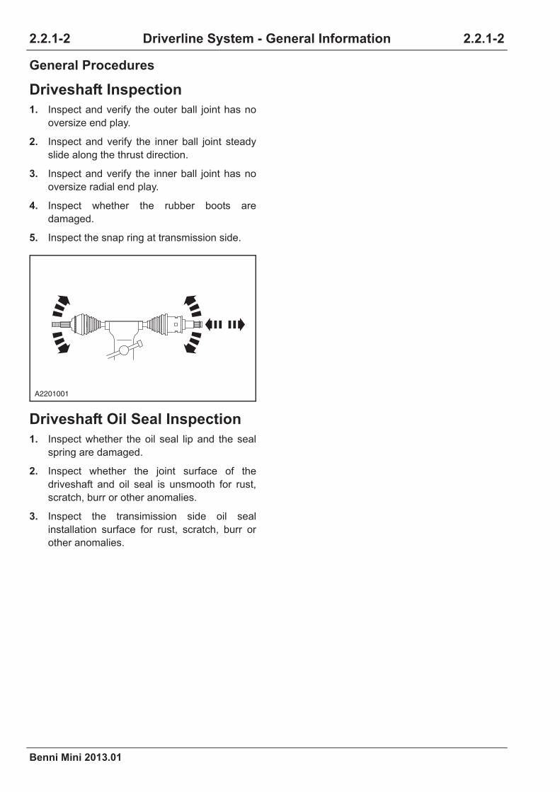
2.2.1-2
Benni Mini 2013.01
2.2.1-2Driverline System - General Information
General Procedures
Driveshaft Inspection
1. Inspect and verify the outer ball joint has no
oversize end play.
2. Inspect and verify the inner ball joint steady
slide along the thrust direction.
3. Inspect and verify the inner ball joint has no
oversize radial end play.
4. Inspect whether the rubber boots are
damaged.
5. Inspect the snap ring at transmission side.
Driveshaft Oil Seal Inspection
1. Inspect whether the oil seal lip and the seal
spring are damaged.
2. Inspect whether the joint surface of the
driveshaft and oil seal is unsmooth for rust,
scratch, burr or other anomalies.
3. Inspect the transimission side oil seal
installation surface for rust, scratch, burr or
other anomalies.
A2201001

Benni Mini 2013.01
2.2.1-3 2.2.1-3Driverline System - General Information
Symptom Diagnosis and Testing
Inspection and Verification
1. Verify customer concerns.
2. Visually inspect whether there is obvious mechanical damage.
3. If the inspection shows obvious evidence of the problem, the fault symptom should be cleared before
the next step.
4. If the visual inspection is ok, confirm the fault and go to the symptom chart.
Symptom Chart
Symptom Possible Sources Action
Driveshaft noises
•Inadequate or contaminated
lube in driveshaft CV joint
Refer to: Driveshaft Noises
(2.2.1 Driverline System - Gen-
eral Information, Symptom
Diagnosis and Testing).•Another component contacting
driveshaft assembly
Clunk noises when accelera-
tion after neutral position
coasting
•CV joint rubber boot crack or
damage
Refer to: Clunk Noises At
Acceleration After Neutral Posi-
tion Coasting (2.2.1 Driverline
System - General Information,
Symptom Diagnosis and Test-
ing).
•CV joint wear or damage
Vibration at high speed
•Wheels out of balance •Wheels balance
•Large radial runout of front
wheel •Refer to driveshaft removal and installa-
tion•Incorrect installation of
driveshaftdriveshaft
Shudder or vibration during
acceleration
•Improper assembling height
caused too large angle of tripod
CV joint
Refer to: Shudder or Vibration
During Acceleration (2.2.1 Driv-
erline System - General Infor-
mation, Symptom Diagnosis
and Testing).•Driveshaft excessively worn or
damaged
Tripod joint or slip ball joint
pullout
•Driveshaft retainer snap ring
missing or not correctly seated in
the differential
•Replace the retainer ring
•Engine/transmission misposi-
tioned
•Inspect the engine mounting bracket
whether it is worn or damaged
•Subframe or chassis distort or
bend•Measure the chassis
•Front suspension component
worn or damaged
•Inspect whether the axle bushing is worn
or the components are distorted (stabilizer
bar, suspension arm and etc.) and replace
them if necessary

2.2.1-4
Benni Mini 2013.01
2.2.1-4Driverline System - General Information
Driveshaft Noises
Clicking, popping or grinding
noises while driving
•Inadequate or contaminated
lube in driveshaft CV joint•inspect, clean and lubricate as necessary
•Another component contacting
driveshaft assembly•Inspect and repair as necessary
•Wheel bearings, brake, suspen-
sion or steering components
worn or damaged
•Inspect and repair as necessary
Driveshaft pullout
•The joint retainer snap ring of
driveshaft and transmission is
distorted
•Driveshaft distorted
•Front strut distorted
•Driveshaft retaining nut dam-
aged
Refer to: Driveshaft Pullout
(2.2.1 Driverline System - Gen-
eral Information, Symptom
Diagnosis and Testing).
Vehicle shimmy at low speed
•Wrong tire dynamic balance
•Wrong wheel alignment
•Wheel hub bearing damaged
•Driveshaft damaged
•Strut damaged
•Stabilizer bar and bushing wear
or damaged
Refer to: Vehicle Shimmy At
Low Speed (2.2.1 Driverline
System - General Information,
Symptom Diagnosis and Test-
ing).
Testing Conditions Details/Results/Actions
1.Inspect whether the driveshaft contacting other components
A.Lift the vehicle.
Refer to: Lifting (1.1.3 Traction and Lifting,
Description and Operation).
B.Inspect whether the driveshaft is twisted by other
debris.
C.Inspect whether the driveshaft contacts other parts.
Normal or not?
Y
Go to step 2.
N
Troubleshooting.
Symptom Possible Sources Action

Benni Mini 2013.01
2.2.1-5 2.2.1-5Driverline System - General Information
2.Inspect the driveshaft rubber boot
A.Inspect whether the driveshaft rubber boot is
damaged.
B.Inspect whether the driveshaft rubber boot is
correctly installed.
C.Inspect whether there is leakage for the driveshaft
joint lubrication.
Normal or not?
Y
Go to step 3.
N
Troubleshooting.
3.Inspect the driveshaft
A.Remove the driveshaft.
B.Inspect the driveshaft.
Refer to: Driveshaft Inspection (2.2.1
Driveline System - General Information,
General Procedures).
Normal or not?
Y
Refer to: (1.1.5 Noises, Vibration and
Harshness).
N
Replace the driveshaft assembly.
Testing Conditions Details/Results/Actions
2.2.1-6
Benni Mini 2013.01
2.2.1-6Driverline System - General Information
Clunk Noises at Acceleration After Neutral Position Coasting
CAUTION: Clunk during accelerating-coasting or start from standstill, may caused by worn
or damage of the wheel driveshaft inner CV joint. This damage normally caused by grease
lacking and/or foreign matter and dirt in the CV joint. It is normally caused by cracking or
damage of the inner CV joint sealing boot.
Testing Conditions Details/Results/Actions
1.Inspect the driveshaft rubber boot
A.Inspect whether the driveshaft rubber boot is
damaged.
B.Inspect whether the driveshaft rubber boot is
correctly installed.
C.Inspect whether there is leakage for driveshaft joint
lube.
Normal or not?
Y
Go to step 2.
N
Troubleshooting.
2.Inspect the driveshaft
A.Remove the driveshaft.
B.Inspect the driveshaft.
Refer to: Driveshaft Inspection (2.2.1
Driveline System - General Information,
General Procedures).
C.Any seized or blocked CV joint shows potential
damage that may lead to breakdown.
Normal or not?
Y
Refer to: (1.1.5 Noises, Vibration and
Harshness).
N
Replace the driveshaft assembly.

Benni Mini 2013.01
2.2.1-7 2.2.1-7Driverline System - General Information
Shudder or Vibration During Acceleration
Testing Conditions Details/Results/Actions
1.Inspect the front strut assembly height
A.Inspect whether the front strut assembly is distorted.
Normal or not?
Y
Go to step 2.
N
Troubleshooting. Replace the front strut assembly
as necessary.
2.Inspect the arm ball
A.Inspect whether there is clearance or damage of the
arm ball.
Normal or not?
Y
Go to step 3.
N
Replace the lower arm ball.
3.Inspect the arm and each mounting bolt
A.Remove all the mounting bolts of the arm and
inspect for looseness.
B.Inspect each arm bushing for damage.
Normal or not?
Y
Go to step 4.
N
Troubleshooting. Replace the arm assembly as
necessary.
4.Inspect the driveshaft rubber boot
A.Inspect whether the driveshaft rubber boot is
damaged.
B.Inspect whether the driveshaft rubber boot is
correctly installed.
C.Inspect whether there is leakage for driveshaft joint
lube.
Normal or not?
Y
Go to step 5.
N
Troubleshooting.

2.2.1-8
Benni Mini 2013.01
2.2.1-8Driverline System - General Information
Driveshaft Pullout
5.Inspect the driveshaft
A.Remove the driveshaft.
B.Inspect the driveshaft.
Refer to: Driveshaft Inspection (2.2.1
Driveline System - General Information,
General Procedures).
Normal or not?
Y
Refer to: (1.1.5 Noises, Vibration and
Harshness).
N
Replace the driveshaft assembly.
Testing Conditions Details/Results/Actions
1.Inspect the driveshaft
A.Inspect whether the driveshaft rubber boot is
damaged.
B.Inspect whether the driveshaft rubber boot is
correctly installed.
Normal or not?
Y
Go to step 2.
N
Troubleshooting.
2.Inspect the driveshaft and the snap ring at transmission side
A.Remove the driveshaft.
B.Inspect the snap ring at transmission side.
Refer to: Driveshaft Inspection (2.2.1
Driveline System - General Information,
General Procedures).
Normal or not?
Y
Go to step 3.
N
Replace the driveshaft assembly.
Testing Conditions Details/Results/Actions
Benni Mini 2013.01
2.2.1-9 2.2.1-9Driverline System - General Information
Driveshaft Swing
3.Inspect the front strut
A.Inspect whether the front strut assembly is
deformed.
Normal or not?
Y
Refer to: (1.1.5 Noises, Vibration and
Harshness).
N
Replace the front strut assembly.
4.Inspect the driveshaft retaining nut
A.Inspect whether the driveshaft retaining nut is
damaged.
Normal or not?
Y
Refer to: (1.1.5 Noises, Vibration and
Harshness).
N
Replace the retaining nut.
Testing Conditions Details/Results/Actions
1.Inspect the driveshaft
A.Inspect whether the driveshaft rubber boot is
damaged.
B.Inspect whether the driveshaft rubber boot is
correctly installed.
C.Inspect whether the driveshaft is bend or deformed.
Normal or not?
Y
Go to step 2.
N
Troubleshooting.
Testing Conditions Details/Results/Actions

2.2.1-10
Benni Mini 2013.01
2.2.1-10Driverline System - General Information
Vehicle Shimmy At Low Speed
2.Inspect the driveshaft and the snap ring at transmission side
A.Remove the driveshaft.
B.Inspect the snap ring at transmission side.
Refer to: Driveshaft Inspection (2.2.1
Driveline System - General Information,
General Procedures).
Normal or not?
Y
Go to step 3.
N
Replace the driveshaft assembly.
Testing Conditions Details/Results/Actions
1.Inspect the wheel
A.Inspect whether the wheel runout is normal.
Refer to: Wheel Runout Inspection (2.1.4
Wheels and Tires, General Procedures).
Normal or not?
Y
Go to step 2.
N
Troubleshooting.
2.Inspect the wheel alignment
A.Inspect whether the wheel alignment is normal.
Normal or not?
Y
Go to step 3.
N
Troubleshooting.
Testing Conditions Details/Results/Actions

Benni Mini 2013.01
2.2.1-11 2.2.1-11Driverline System - General Information
3.Inspect the driveshaft
A.Inspect whether the driveshaft rubber boot is
damaged.
B.Inspect whether the driveshaft rubber boot is
correctly installed.
C.Inspect whether the driveshaft is bend or deformed.
Normal or not?
Y
Go to step 4.
N
Troubleshooting.
4.Inspect the suspension system
A.Inspect the suspension system.
Refer to: (2.1.1 Suspension System - Gen-
eral Information, General Procedures).
Normal or not?
Y
Refer to: (1.1.5 Noises, Vibration and
Harshness).
N
Troubleshooting.
Testing Conditions Details/Results/Actions


Benni Mini 2013.01
2.2.2-1 2.2.2-1Driveshaft
Specifications
Material specifications
Capacity
Torque Specifications
Item Specification
High-performance grease (color: black), CV joint G.A.Cpalex GTE
Other alternative grease Molybdenum disulfide
High-performance grease, outer CV joint 70±10 g
High-performance grease, inner CV joint 65±10 g
Item Nm lb-ft lb-in
Tie rod ball joint to steering knuckle
retaining nut48 35 -
Front arm ball joint to knuckle bolt nut 50 37 -
Wheel hub bearing fixing nut 275 200 -
Tire nut 85 63 -
Front strut and shock absorption spring
assembly retaining nut37 27 -
2.2.2 Driveshaft

2.2.2-2
Benni Mini 2013.01
2.2.2-2Driveshaft
Description and Operation
System Overview
The halfshafts have constant velocity (CV) joints
at both ends.
• Inner CV joints (composed of constant
velocity ball, spider joint, cylindrical roller,
steel ball and universal joint housing) are
installed on the drive axle.
• Outer CV joints (composed of steel ball,
ball retainer and universal joint housing)
are installed to the wheel side.
• Inner CV joints are fixed on the
differential through differential spring ring.
• Outer CV joints are fixed on the wheel
hub bearing.
The halfshaft transmits torque from the engine to
the wheels. In order to be adaptive to the vertical
motion of the wheel and the engine, the halfshaft
is required to rotate by different lengths and
angles.
The tripode joints allow for changes in halfshaft
length during axial movements.
Cautions for Halfshaft
CAUTION: The constant velocity joints are
not allowed to just clamp the drive axle.
CAUTION: Be very carefully when remov-
ing, installing, disassembling or assem-
bling the drive axle. The following
instruction must be followed:
• Do not push-and-pull the CV joint when
removing the halfshaft.
• The operating angle of the CV joint must
not be bent more than 22.5 degrees.
• Check whether the polished surface and
the spline are damaged.
• The rubber boot is prohibited to contact
with sharp edge and a hot engine or
exhaust system.
• Do not drop the halfshaft, since it may
caused inner damage to the rubber boot
with no visual evidence from the outside
inspection.
• Do not use the halfshaft as pry tool during
the installation of other components. Do
not hang the halfshaft randomly.
• Knock on the tripod housing can cause
damage to the universal joint.
Front wheel balance
WARNING: When the vehicle is completely
lifted off the ground, using the portable
wheel balancer may result in damage to
the constant velocity joint or the rubber
boot, which is caused by too large a bent
angle of the universal joint.
Place the push-type jack below the lower
cross arm when using the portable wheel bal-
ancer to avoid too large a bend of the univer-
sal joint during vehicle lifting.
Conditions permitting, it would be best to
remove the wheel on the fixed wheel bal-
ancer.
Lifting the vehicle
WARNING: It is forbidden to use the
universal joint or the halfshaft as jack.
Drag the vehicle
CAUTION: it is forbidden to bind the rope
on the halfshaft.
Body bottom protection and rust pre-
vention
CAUTION: Cover the rubber boot when
carrying out the body bottom protection or
rust prevention treatment.
Dirt on the rubber boot makes the material
age in advance, while foreign matter on the
halfshaft will cause the imbalance of the half-
shaft.

Benni Mini 2013.01
2.2.2-3 2.2.2-3Driveshaft
Exploded View
Item Description Item Description
1 Halfshaft retaining nut 13 Differential spring ring
2 Fixed end cage universal joint 14 Halfshaft retaining nut
3 Fixed end large clamp 15 Fixed end cage universal joint
4 Fixed end rubber boot 16 Fixed end large clamp
5 Fixed end small clamp 17 Fixed end rubber boot
6 Damper 18 Fixed end small clamp
7 Damper clamp 19 Left shaft lever
8 Right shaft lever 20 Moveable end small clamp
9 Moveable end small clamp 21 Moveable end rubber boot
10 Moveable end rubber boot 22 Moveable end large clamp
11 Moveable end large clamp 23 Axially moveable universal joint
12 Axially moveable universal joint 24 Differential spring ring
141516
21 20
19
1
2 3
4
6
9
810
13
5
7
12
11
24
23
22
18
17
A2202016

2.2.2-4
Benni Mini 2013.01
2.2.2-4Driveshaft
Symptom Diagnosis and Testing
Refer to: Symptom Chart (2.2.1 Driveline
System - General Information, Symptom
Diagnosis and Testing).

Benni Mini 2013.01
2.2.2-5 2.2.2-5Driveshaft
Disassembly and Assembly
Inner Constant Velocity (CV) Joint and Rubber Boot
Removal
Special Tool
Material
Halfshaft Rubber Boot
Clamp Remover
CA201-002
Halfshaft Rubber Boot
Clamp Installer
CA201-008
Item Model
High
performance
grease
G.A.Cpalex GTE
1. Remove the halfshaft.
Refer to: Left-Hand Halfshaft (2.2.2 Drive
shaft, Removal and Installation).
2. Remove the ball joint assembly.
1. Remove the rubber boot clamp with a spe-
cial tool.
Special Tool: CA201-002
2. Disassemble the ball joint assembly.
3. Clear the grease in the CV joint.
CA201-002
CA201-008
2
1
1
A2202001
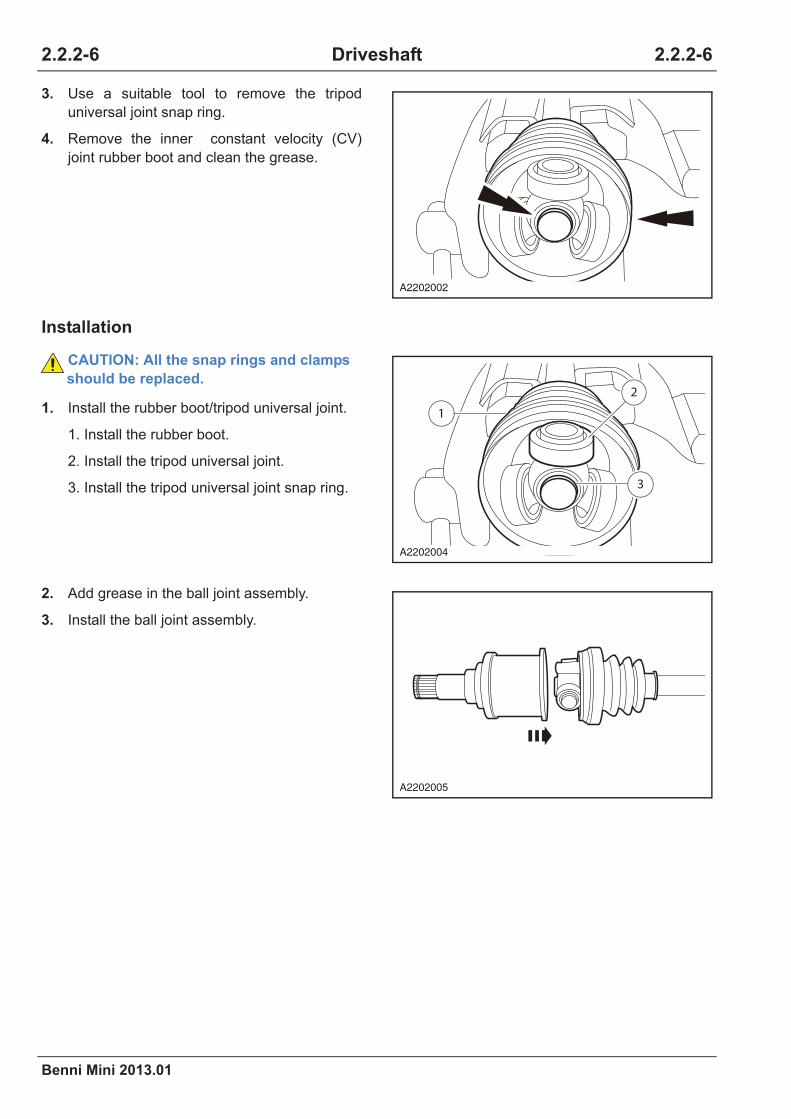
2.2.2-6
Benni Mini 2013.01
2.2.2-6Driveshaft
Installation
3. Use a suitable tool to remove the tripod
universal joint snap ring.
4. Remove the inner constant velocity (CV)
joint rubber boot and clean the grease.
CAUTION: All the snap rings and clamps
should be replaced.
1. Install the rubber boot/tripod universal joint.
1. Install the rubber boot.
2. Install the tripod universal joint.
3. Install the tripod universal joint snap ring.
2. Add grease in the ball joint assembly.
3. Install the ball joint assembly.
A2202002
1
2
3
A2202004
A2202005

Benni Mini 2013.01
2.2.2-7 2.2.2-7Driveshaft
4. Install the rubber boot clamp with a special
tool.
Special Tool: CA201-008
CAUTION: The size of the clamp mouth C
should not be more than 1.5 mm.
CAUTION: The tightening torque for 0.8
mm thick clamp is 12 Nm, the tightening
torque for 1.1 mm thick clamp is 20 Nm.
5. Install the halfshaft.
Refer to: Left-Hand Halfshaft (2.2.2 Drive
shaft, Removal and Installation).
C
A2202008

2.2.2-8
Benni Mini 2013.01
2.2.2-8Driveshaft
Outer Constant Velocity (CV) Joint and Rubber Boot
Removal
Special Tool
Halfshaft Rubber Boot
Clamp Remover
CA201-002
Halfshaft Rubber Boot
Clamp Installer
CA201-008
Item Model
High
performance
grease
2LN584/L0K575 GS
1. Remove the halfshaft.
Refer to: Left-Hand Halfshaft (2.2.2 Drive
shaft, Removal and Installation).
2. Remove the rubber boot clamp.
1. Remove the rubber boot clamp with a spe-
cial tool.
Special Tool: CA201-002
2. Detach the rubber boot.
3. Clean the grease.
CA201-002
CA201-008
2
11
A2202009

Benni Mini 2013.01
2.2.2-9 2.2.2-9Driveshaft
3. Take out the retainer ball cage and the
supporter from the case.
1.Use a needle nose pliers to shove off the
snap ring.
2.Remove the constant velocity universal
joint with tapping a copper bar.
4. Take out the drive shaft from the universal
joint.
1.Take out the drive shaft 1 from the universal
joint.
2.Take out the snap spring 2 from the univer-
sal joint.
3.Take out the rubber boot 3.
5. Take out the steel ball from the ball cage.
1. Rotate the retainer ball cage.
2. Take out the retainer ball cage.
6. Take out the steel ball from the ball cage.
7. Check the wear on the moving surface.
CAUTION: Ensure the ball cage, the case,
the ball bearing and the supporter will not
contact the grease and oil.
A2202010
1
3
2
A2202011
2
1
A2202012
A2202013

2.2.2-10
Benni Mini 2013.01
2.2.2-10Driveshaft
Installation
CAUTION: All the snap rings and clamps
should be replaced.
1. Install the steel ball on the ball cage
supporter.
2. Install the retainer ball cage.
1. Install the retainer ball cage into the case.
2. Rotate the retainer ball cage.
3. Put the halfshaft into the CV joint.
1. Install the rubber boot and the inner clamp.
2. Insert a new snap ring in the halfshaft CV
joint groove.
3.Insert the halfshaft into the halfshaft CV
joint until it meshes the snap spring .
4. Fill the halfshaft outer CV joint with high-
performance grease.
A2202013
1 2
A2202014
A2202015
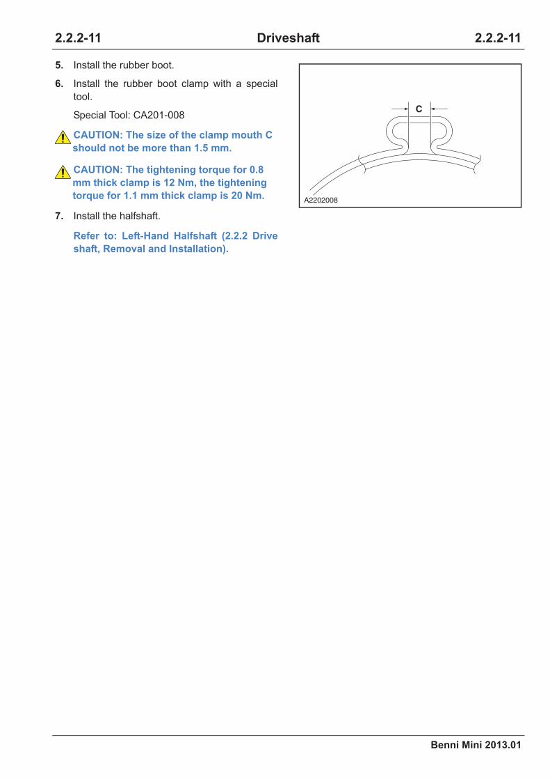
Benni Mini 2013.01
2.2.2-11 2.2.2-11Driveshaft
5. Install the rubber boot.
6. Install the rubber boot clamp with a special
tool.
Special Tool: CA201-008
CAUTION: The size of the clamp mouth C
should not be more than 1.5 mm.
CAUTION: The tightening torque for 0.8
mm thick clamp is 12 Nm, the tightening
torque for 1.1 mm thick clamp is 20 Nm.
7. Install the halfshaft.
Refer to: Left-Hand Halfshaft (2.2.2 Drive
shaft, Removal and Installation).
C
A2202008

2.2.2-12
Benni Mini 2013.01
2.2.2-12Driveshaft
Removal and Installation
Left-Hand Halfshaft
Removal
Special Tool
Halfshaft Remover
CA201-006
1. Remove the wheel.
Refer to: Wheel and Tire (2.1.4 Wheels and
Tires, Removal and Installation).
2. Lift the vehicle.
Refer to: Lifting (1.1.3 Traction and Lifting,
Description and Operation).
3. Remove the halfshaft retaining nut.
Torque: 275 Nm
4. Remove the tie rod ball joint and the stabilizer
bar.
1.Detach the cotter pin and remove the tie rod
ball joint retaining nut.
Torque: 48 Nm
2.Detach the cotter pin and remove the stabi-
lizer bar retaining nut.
Torque: 92 Nm
CA201-006
A2202019
1
2
A2202020

Benni Mini 2013.01
2.2.2-13 2.2.2-13Driveshaft
5. Remove the front stabilizer bar assembly.
1.Remove both stabilizer bar seat retaining
bolts.
Torque: 72 Nm
2.Detach the front stabilizer bar assembly.
6. Detach the front arm ball joint from the
steering knuckle.
1.Remove the retaining nut of the front arm
ball joint.
Torque: 50 Nm
2.Detach the front arm ball joint from the
steering knuckle.
7. Use a proper puller. Detach the driveshaft
from the wheel hub.
CAUTION: Protect the driveshaft to
prevent damage to the constant velocity
(CV) joint. The inner CV joint operating
angle must not be bent more than 22.5
degrees. The outer CV joint operating
angle must not be bent more than 45
degrees.
8. Place a suitable container under the
transmission.
9. Remove the driveshaft from the transmission
using a special tool skillfully.
Special Tool: CA201-006
CAUTION: If it's hard to remove the inner
ball cage form the transmission, do not
force to pry and pull it. At this point, put
the driveshaft back to the transmission,
rotate for 90 degrees to remove it.
2
1
A2202021
A2202022
A2202018
201-006
A2202023

2.2.2-14
Benni Mini 2013.01
2.2.2-14Driveshaft
Installation
1. Install the halfshaft to the transaxle.
CAUTION: Protect the halfshaft to prevent
damage to the constant velocity (CV) joint.
The inner CV joint operating angle must
not be bent more than 22.5 degrees. The
outer CV joint operating angle must not be
bent more than 45 degrees.
CAUTION: When inserting the driveshaft,
use the oil seal installer (provided with oil
seal) to protect the oil seal.
CAUTION: Make sure the retainer ring is
installed in the groove already when
installing a new retainer ring.
2. Install the halfshaft to the wheel hub bearing.
3. Install the arm ball joint.
4. Install the wheel hub retaining nut.
5. Replace the tie rod ball joint.
6. Remove the front stabilizer bar assembly.
7. Install the wheel.
Refer to: Wheel and Tire (2.1.4 Wheels and
Tires, Removal and Installation).
8. Tighten the left front strut retaining nut.
Right-Hand Halfshaft
Refer to: Left-Hand Halfshaft (2.2.2 Drive
shaft, Removal and Installation).
A2202024
A2202025

Benni Mini 2013.01
2.2.3-1 2.2.3-1Differential
Specifications
General Specifications
Torque Specifications
Item Specification
Transmission oil type BOT130M, GL-4, 75W/90
Manual transmission oil capacity 2.1 ± 0.1 L
Item Nm lb-ft lb-in
Final drive driven gear fixed bolt 90 -
2.2.3 Differential

2.2.3-2
Benni Mini 2013.01
2.2.3-2Differential
Description and Operation
Exploded View
Item Description Item Description
1 Differential left bearing 9 Differential cover
2 Differential bolt 10 Induction gear
3 Final drive gear 11 Differential right bearing
4 Differential halfshaft washer 12 Planetary gear shaft pin
5 Differential halfshaft gear 13 Differential halfshaft gear
6 Planetary gear washer 14 Planetary gear
7 Planetary gear 15 Planetary gear washer
8 Planetary gear washer 16 Planetary gear shaft
12
11
15
16
1
2
3
4
5
8
6
9
10
7 14
13
A2203001
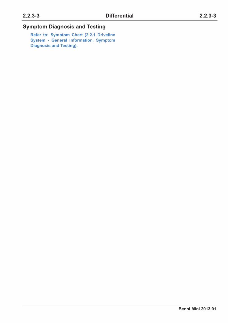
Benni Mini 2013.01
2.2.3-3 2.2.3-3Differential
Symptom Diagnosis and Testing
Refer to: Symptom Chart (2.2.1 Driveline
System - General Information, Symptom
Diagnosis and Testing).

2.2.3-4
Benni Mini 2013.01
2.2.3-4Differential
Disassembly and Assembly
Differential
Disassembly
1. Remove the vehicle speed sensor signal
gear.
CAUTION: Remove the induction gear ring
or bearing with a suitable tool.
CAUTION: Use the vise holder protector
all the time when using the vise.
2. Remove the final drive gear bolts to the
differential.
3. Remove the differential left bearing.
CAUTION: Remove the bearing with a
suitable tool.
CAUTION: Use the vise holder protector
all the time when using the vise.
A2203002
×8
A2203003
A2203004

Benni Mini 2013.01
2.2.3-5 2.2.3-5Differential
4. Remove the planetary gear shaft pin.
CAUTION: Remove the planetary gear
shaft pin with a suitable tool.
5. Remove the planetary gear shaft.
6. Rotate the drive shaft gear to remove the
planetary gear and the planetary gear gasket.
7. Remove the differential right halfshaft and the
differential halfshaft gasket.
A2203005
A2203006
A2203007
A2203008
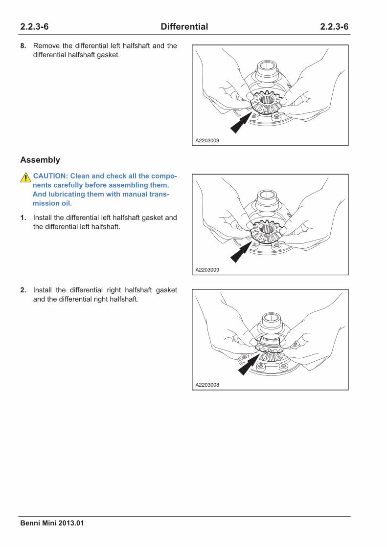
2.2.3-6
Benni Mini 2013.01
2.2.3-6Differential
Assembly
8. Remove the differential left halfshaft and the
differential halfshaft gasket.
CAUTION: Clean and check all the compo-
nents carefully before assembling them.
And lubricating them with manual trans-
mission oil.
1. Install the differential left halfshaft gasket and
the differential left halfshaft.
2. Install the differential right halfshaft gasket
and the differential right halfshaft.
A2203009
A2203009
A2203008

Benni Mini 2013.01
2.2.3-7 2.2.3-7Differential
3. Install the planetary gear and the gasket,
rotate the driveshaft gear.
4. Install the planetary gear shaft.
CAUTION: Align the planetary gear shaft
pin hole and the installing hole on the dif-
ferential case.
5. Install the planetary gear shaft pin.
CAUTION: Install the planetary gear shaft
pin with a suitable tool.
6. Install the final drive gear bolts to the
differential.
Torque: 90 Nm
CAUTION: Lock the ring gear fixing bolt
with hands and fasten it to the specified
torque with average strength.
CAUTION: Install the new ring gear fixing
bolt.
A2203010
A2203011
A2203012
×8
A2203016

2.2.3-8
Benni Mini 2013.01
2.2.3-8Differential
7. Install the differential left gear.
CAUTION: 1. Check whether the color of the tapered
roller bearing bottom changes.
2. Check the bearing for wear or rotating
clamping stagnation.
CAUTION: Install new bearing and differ-
ential oil seal if the above situation exists.
WARNING: All the gears and bearings
have directions. Do not use them wrongly.
8. Install the induction gear ring.
CAUTION: The induction gear ring has its
mounting position.
9. Install the differential right bearing.
CAUTION: 1.Check whether the color of
the bearing changes. 2. Check the bearing
for wear or rotating clamping stagnation.
CAUTION: Install the new bearing and the
differential oil seal if the above situation
exists.
WARNING: All the gears and the bearings
have directions. Do not use them wrongly.
A2203013
A2203014
A2203015

Benni Mini 2013.01
Brake System
2.3 Brake System
2012 Benni Mini
2.3.1 Brake System - General Informa
Specifications ................................................................................................................................... 2.3.1-1
Material Specifications.............................................................................................................. 2.3.1-1
General Specifications.............................................................................................................. 2.3.1-1
Description and Operation ............................................................................................................... 2.3.1-2
System Overview...................................................................................................................... 2.3.1-2
Location View ........................................................................................................................... 2.3.1-3
General Procedures......................................................................................................................... 2.3.1-4
Symptom Diagnosis and Testing.................................................................................................... 2.3.1-11
Inspection and Verification...................................................................................................... 2.3.1-11
Symptom Chart....................................................................................................................... 2.3.1-12
Uneven Brake - Deviation Diagnosis...................................................................................... 2.3.1-19
Shaking/Vibration While Braking Diagnosis ........................................................................... 2.3.1-21
Brake Pedal Go Down Quickly Diagnosis .............................................................................. 2.3.1-23
Low Brake Pedal or Feeling Like Sponge Diagnosis.............................................................. 2.3.1-24
Brake Lock While Slightly Depress the Brake Diagnosis ....................................................... 2.3.1-26
Depress the Brake Pedal and Hold It Down In Depressed Position, and the Pedal Eases Down
Slowly Diagnosis .................................................................................................................... 2.3.1-27
Brake Drag Diagnosis............................................................................................................. 2.3.1-29
2.3.2 Rear Drum Brake
Specification..................................................................................................................................... 2.3.2-1
Material Specifications.............................................................................................................. 2.3.2-1
Rear Drum Brake Specification ................................................................................................ 2.3.2-1
Torque Specifications................................................................................................................ 2.3.2-1
Description and Operation ............................................................................................................... 2.3.2-2
Brake System ........................................................................................................................... 2.3.2-2
Component Description ............................................................................................................ 2.3.2-2
Exploded View.......................................................................................................................... 2.3.2-3
Removal and Installation.................................................................................................................. 2.3.2-4
Brake Drum .............................................................................................................................. 2.3.2-4
Brake Shoe............................................................................................................................... 2.3.2-5
Brake Slave Cylinder ................................................................................................................ 2.3.2-9
Brake Bottom Plate................................................................................................................. 2.3.2-11
Table of Contents Pages

Benni Mini 2013.01
Brake System
2.3.3 Front Disc Brake
Specifications ...................................................................................................................................2.3.3-1
Material Specifications ..............................................................................................................2.3.3-1
Front Disc Brake Specification..................................................................................................2.3.3-1
Torque Specifications................................................................................................................2.3.3-1
Description and Operation................................................................................................................2.3.3-2
System Overview......................................................................................................................2.3.3-2
Component Description ............................................................................................................2.3.3-2
Exploded View ..........................................................................................................................2.3.3-3
Disassembly and Assembly .............................................................................................................2.3.3-4
Brake Caliper ............................................................................................................................2.3.3-4
Removal and Installation ..................................................................................................................2.3.3-6
Brake Pad .................................................................................................................................2.3.3-6
Brake Caliper ............................................................................................................................2.3.3-8
Brake Disc ................................................................................................................................2.3.3-9
2.3.4Parking Brake and Actuation
Specifications ...................................................................................................................................2.3.4-1
Torque Specifications................................................................................................................2.3.4-1
Description and Operation................................................................................................................2.3.4-2
System Overview......................................................................................................................2.3.4-2
General Procedures .........................................................................................................................2.3.4-3
Parking Brake Cable Adjustment ..............................................................................................2.3.4-3
Symptom Diagnosis and Testing ......................................................................................................2.3.4-4
Inspection and Verification........................................................................................................2.3.4-4
Symptom Chart .........................................................................................................................2.3.4-5
Parking Brake Not Work (Failure) Diagnosis/Poor Parking Brake ............................................2.3.4-6
Parking Brake Not Release (Lag) Diagnosis ............................................................................2.3.4-8
Parking Brake Indicator Always On Diagnosis .........................................................................2.3.4-9
Removal and Installation ................................................................................................................2.3.4-12
Parking Brake Control.............................................................................................................2.3.4-12
Parking brake cable ................................................................................................................2.3.4-13
Parking Brake Warning Lamp Switch .....................................................................................2.3.4-15
2.3.5 Hydraulic Brake Actuation
Specification .....................................................................................................................................2.3.5-1
Material Specifications ..............................................................................................................2.3.5-1
Torque Specifications................................................................................................................2.3.5-1

Benni Mini 2013.01
Brake System
Description and Operation ............................................................................................................... 2.3.5-2
System Overview...................................................................................................................... 2.3.5-2
Component Description ............................................................................................................ 2.3.5-2
Removal and Installation.................................................................................................................. 2.3.5-3
Brake Master Cylinder and Brake Fluid Reservoir ................................................................... 2.3.5-3
Brake, Clutch and Accelerator Pedal Assembly (MT) .............................................................. 2.3.5-5
Brake Pedal Assembly (AT)......................................................................................................2.3.5-8
2.3.6 Power Brake Actuation
Specifications ................................................................................................................................... 2.3.6-1
Torque Specifications................................................................................................................ 2.3.6-1
Description and Operation ............................................................................................................... 2.3.6-2
System Overview...................................................................................................................... 2.3.6-2
Location View ........................................................................................................................... 2.3.6-2
Removal and Installation.................................................................................................................. 2.3.6-3
Brake Booster........................................................................................................................... 2.3.6-3
2.3.7 Anti-lock Control
Specifications ................................................................................................................................... 2.3.7-1
Material Specifications.............................................................................................................. 2.3.7-1
Torque Specifications................................................................................................................ 2.3.7-1
Description and Operation ............................................................................................................... 2.3.7-2
System Overview...................................................................................................................... 2.3.7-2
Component Description ............................................................................................................ 2.3.7-2
General Procedures......................................................................................................................... 2.3.7-7
Inspection and Verification........................................................................................................ 2.3.7-7
Symptom Diagnosis and Testing...................................................................................................... 2.3.7-8
Intermittent Malfunction Diagnosis ........................................................................................... 2.3.7-8
ABS Warning Lamp Is OFF Diagnosis ................................................................................... 2.3.7-10
ABS Warning Lamp Always ON Diagnosis............................................................................. 2.3.7-11
DTC Diagnosis and Test ................................................................................................................ 2.3.7-13
Control Module Terminal List .................................................................................................. 2.3.7-13
DTC Code List ........................................................................................................................ 2.3.7-14
Data Stream List ..................................................................................................................... 2.3.7-15
Active Test List........................................................................................................................ 2.3.7-16
Diagnostic Tool Can Not Communicate With the Vehicle Diagnosis ...................................... 2.3.7-17
DTC Diagnosis Chart.............................................................................................................. 2.3.7-18
Power Supply Fault and Hydraulic Electrical Control Unit Assembly Internal Fault Diagnosis ..2.3.7-19

Benni Mini 2013.01
Brake System
Wheel Speed Sensor Diagnosis .............................................................................................2.3.7-20
Abnormal Data Bus Diagnosis ................................................................................................2.3.7-23
Brake Lamp Switch Fault ........................................................................................................2.3.7-25
Removal and Installation ................................................................................................................2.3.7-28
Hydraulic Control Unit (HCU)..................................................................................................2.3.7-28
Rear Wheel Speed Sensor .....................................................................................................2.3.7-30
Front Wheel Speed Sensor.....................................................................................................2.3.7-32
Rear Wheel Speed Sensor Ring(s).........................................................................................2.3.7-33
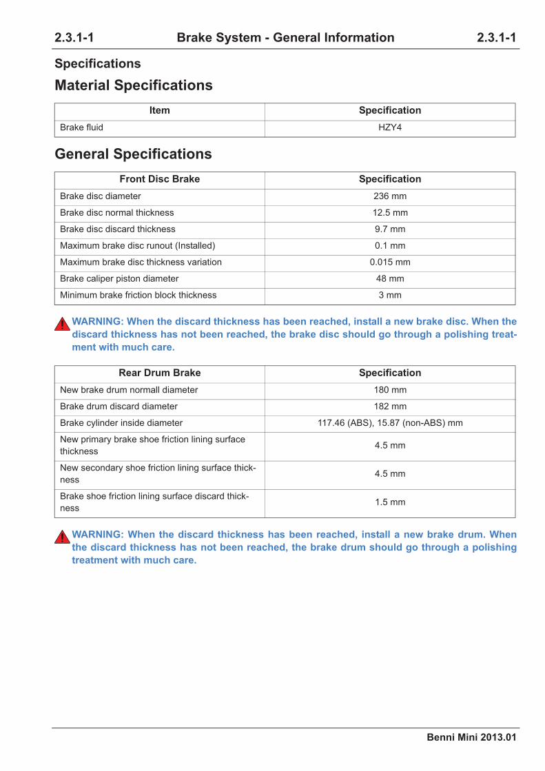
Benni Mini 2013.01
2.3.1-1 2.3.1-1Brake System - General Information
Specifications
Material Specifications
General Specifications
WARNING: When the discard thickness has been reached, install a new brake disc. When the
discard thickness has not been reached, the brake disc should go through a polishing treat-
ment with much care.
WARNING: When the discard thickness has been reached, install a new brake drum. When
the discard thickness has not been reached, the brake drum should go through a polishing
treatment with much care.
Item Specification
Brake fluid HZY4
Front Disc Brake Specification
Brake disc diameter 236 mm
Brake disc normal thickness 12.5 mm
Brake disc discard thickness 9.7 mm
Maximum brake disc runout (Installed) 0.1 mm
Maximum brake disc thickness variation 0.015 mm
Brake caliper piston diameter 48 mm
Minimum brake friction block thickness 3 mm
Rear Drum Brake Specification
New brake drum normall diameter 180 mm
Brake drum discard diameter 182 mm
Brake cylinder inside diameter 117.46 (ABS), 15.87 (non-ABS) mm
New primary brake shoe friction lining surface
thickness4.5 mm
New secondary shoe friction lining surface thick-
ness4.5 mm
Brake shoe friction lining surface discard thick-
ness1.5 mm
2.3.1 Brake System - General Informa-

2.3.1-2
Benni Mini 2013.01
2.3.1-2Brake System - General Information
Description and Operation
System Overview
The braking system is of a diagonally split, dual-
circuit design featuring front disc and rear drum
brakes.
Each pair of wheels is equipped with a hydraulic
system with a separate circuit. The front brake
caliper is of floating type disc brake design
installed on the steering knuckle to ensure the
brake forces acting on the two brake frictions are
equal.
The brake drum uses regular design. It consists
of the brake primary shoe adhesive with a lining
on the secondary shoe. It can not realize the
automatic adjustment of the brake clearance
when braking.
The parking brake control lever is located
between the two front seats, the rear brake is
controlled through the cable device. Opening the
decorative cover in front of the rear cup holder
can control the parking brake adjustment.
The brake master cylinder is of a longitudinal tan-
dem design and directly linked to a brake booster
which reduces the brake pedal effort. The longitu-
dinal tandem design will make sure that in the
event of one brake circuit failing the other will
remain fully operational. The brake master cylin-
der and the brake booster are located at the left
side of the engine compartment.
On the basis of the basic brake, the electronic
hydraulic control unit and the wheel speed sen-
sors are added to the anti-lock brake (ABS) sys-
tem equipped in the vehicle with higher
configuration. The hydraulic system has a sepa-
rate circuit for each wheel. The electronic control
unit collects the speed signal of the four wheels
through the speed sensors and adjusts the brake
pressure during the braking through the hydraulic
control unit so as to make sure that the rear
wheels will not be locked before the front wheels
to guarantee the safety.
The proportioning valve is located on the outlet
pipe of the brake master cylinder with base con-
figuration. The valve can control the hydraulic
pressure applied to the brake at the rear brake so
as to reduce the risk of locking the rear wheel dur-
ing braking.

Benni Mini 2013.01
2.3.1-3 2.3.1-3Brake System - General Information
Location View
Item Description Item Description
1 Right front wheel speed sensor assembly 8 Right rear wheel speed sensor assembly
2 Electronic hydraulic control unit 9 Brake drum
3 Brake fluid reservoir 10 Left rear wheel speed sensor assembly
4 Brake booster 11 Left parking brake cable
5 Parking brake handle 12 Brake disc
6 Cable equalizer 13 Brake caliper
7 Right parking brake cable 14 Left front wheel speed sensor assembly
14 13 12
11
10 9
1 5
7 8
63 4
2
A2301001

2.3.1-4
Benni Mini 2013.01
2.3.1-4Brake System - General Information
General Procedures
General Procedures
Road Test
WARNING: The road test technicians must
be trained with good driving skills.
The road test is carried out to compare the actual
braking performance with standard performance
expected by the driver. The ability to compare and
judge the braking performance depends on the
technician's experience. The technician must
have thorough knowledge of the brake system
working principle and receive a systematic
instruction to make correct comparison and
detect problems.
Before a road test, confirm the vehicle meet the
conditions as follow.
• The tires have not been excessively
worn, with the same tire tread on both left
and right tires.
• The tire pressure is within the
specification range.
• Correct wheel alignment
• Normal brake fluid level
• The brake system indicator is normal
without any trouble code.
The road test must be done on a dry, clean and
even road. An experienced technician will always
establish a route that will be used for all brake
diagnosis road tests. The roads selected will be
reasonably smooth and flat rather than gravel or
rough road. Gravel or bumpy roads are not suit-
able because the surface does not allow the tires
to grip the road equally. Crowned roads should
be avoided because of the large amount of the
weight shifted to the low set of wheels on this type
of road. Once the route is established and consis-
tently used, the road surface variable can be elim-
inated from the test results.
Before a road test, obtain a complete description
of the customer concerns or suspected condition.
From the description, the technician can match
the possible sources with the symptoms. Certain
components will be tagged as possible suspect
problems while others will be eliminated by the
evidence. More importantly, according to the
description of the customer, the technician can
inspect or eliminate the potential hazards before
the road best. The technician can also put all
problems on some particular components, vehicle
speed or conditions, such approach helps deter-
mine a method of carrying a road test.
A road test always starts with the general inspec-
tion for the brake performance. According to the
description of the customer, the vehicle braking
should be inspected with different pedal pres-
sures under different vehicle speeds. To deter-
mine if the concern is in the front or rear brake
system, use the brake pedal and then use the
parking brake control. If the condition (pull, vibra-
tion, isolation) occurs only with the parking brake,
the concern is in the rear brake system.
During the road test, the brake locking should be
avoided. Such situation does not show the brake
works normally. A heavily braked and turning
wheel will stop the vehicle in a shorter distance
than locked brakes.
If the concern becomes evident during this check,
verify it fits the description given before the road
test. If the concern is not evident, attempt to dupli-
cate the condition using the information from the
description.
If a concern exists, use the symptom chart in
order to isolate it to a specific sub-system and
related condition description. From this descrip-
tion, a list of possible sources can be used to fur-
ther narrow the cause to a specific component or
condition.
Hydraulic Leak Inspection
CAUTION: In normal condition, the brake
fluid level goes down as the brake shoe is
worn. The brake fluid level will become
excessively lower if the brake shoe gets
worn beyond the specification. It shows
that there is brake fluid leak in the brake
system if the brake shoe wear is within the
specification and the brake fluid level also
gets excessively lower.
CAUTION: Since the brake and clutch
share the same brake fluid reservoir, the
brake fluid in the reservoir would decrease
due to the clutch leak.

Benni Mini 2013.01
2.3.1-5 2.3.1-5Brake System - General Information
CAUTION: When the vehicle is running on
a rainy or snowy day, the leak trace can be
washed away since the brake fluid is water
soluble.
Inspect by the approaches as follows:
1. Confirm whether the brake fluid level is
excessively low or goes down too fast.
2. Inspect the trace of the brake fluid leak
visually.
3. Remove the front wheels.
Refer to: (2.3.3 Front Disc Brake, Removal
and Installation).
Inspect the front brake slave cylinder for any
leak and the brake shoe for any wear.
4. Remove the rear wheels and the brake drum.
Refer to: (2.3.2 Rear Drum Brake, Removal
and Installation).
Inspect the rear brake slave cylinder for any
leak and the brake shoe for any wear.
5. Remove the brake master cylinder.
Refer to: (2.3.5 Hydraulic Brake Control,
Removal and Installation).
Inspect the brake master cylinder piston seal
for any leak.
6. Service the possible breakdowns above and
carry out the brake system bleeding.
Refer to: Brake System Bleeding (2.3.1
Brake System - General Information, Gen-
eral Procedures).
Brake Pedal Remaining Travel Inspec-tion
The brake pedal remaining travel should be
inspected when the excessive brake pedal travel
is felt or the pedal reaches the bottom during
applying the brake.
1. With the transmission in neutral position, pull
up the handle brake lever and run the engine
at idle speed.
2. Lightly depress the pedal for 3 or 4 times.
3. Keep 15 s to replenish the booster vacuum.
CAUTION: The increased resistance may
feel like the brake pedal has reached bot-
tom.
4. Depress the brake pedal until it stops moving
downwards or there is no increased
resistance.
5. Hold the brake pedal while increasing the
engine speed to 2,000 rpm.
CAUTION: The increasing of engine intake
manifold vacuum causes the brake pedal
to move downwards (additional move-
ment).
6. Release the accelerator pedal and then
observe the downward movement of the
brake pedal as the engine speed decreases
to idle.
Requirement: The application of the additional
travel to the brake master cylinder can not cause
the brake pedal to reach the bottom, otherwise:
Refer to: Long Brake Pedal Travel (2.3.1
Brake System - General Information,
Removal and Installation).
Vacuum Booster Inspection
1. Inspect the brake fluid level.
2. With the transmission in neutral position, pull
up the parking brake and run the engine at
idle speed.
3. Shut down the engine, depress and release
the brake pedal for several times to eliminate
the vacuum in the system, then depress the
brake pedal and hold it.

2.3.1-6
Benni Mini 2013.01
2.3.1-6Brake System - General Information
4. Start the engine. The brake pedal moves
downwards if the vacuum system is
functioning. The vacuum system is not
functioning if the downward movement of the
pedal can not be felt.
5. Remove the vacuum hose at the side of the
brake booster. Manifold vacuum is available
at the brake booster end of the hose when
the engine runs at idle speed. Feel the
vacuum with hand or measure it with vacuum
meter. Inspect the vacuum hose for block,
sealing or leak if there is no or little vacuum.
Make sure that all unused vacuum outlets are
correctly capped, hose connectors are
secured and vacuum hoses are in good
condition, thus, the vacuum in the manifold is
functioning. Reconnect the vacuum hose to
the brake booster and repeat step 3. Install a
new brake booster if no downward movement
of the brake pedal is felt.
6. Run the engine for 10 seconds at fast idle
speed. Depress the brake pedal with an
approximately 889 N (20 lb) force 10 min after
the engine shuts down. The brake pedal
should be felt the same way when the engine
is running (normal boosting).
7. If the brake pedal feels hard, check and
confirm that the check valve works normally,
and then repeat the testing. If the brake pedal
still feels hard, install a new brake booster.
If brake pedal feels soft, discharge the brake sys-
tem.
Refer to: Brake System Bleeding (2.3.1
Brake System - General Information, Gen-
eral Procedures).
Brake Master Cylinder Inspection
CAUTION: Before the diagnosis, make
sure that the brake fluid level and the
warning indicator work normally, there is
no trouble code in the brake system.
Generally, for any faults of the brake system,
the first and best way is feeling on the brake
pedal. For diagnosis of the brake master cyl-
inder, inspect the feeling on the brake pedal
as evidence. Inspect if the brake warning indi-
cator lamp flashes and inspect the brake liq-
uid level.
Normal Conditions
In normal condition, changes in the brake pedal
feel or travel indicates that something could be
wrong in the brake system. But the following con-
ditions are considered normal and indicate that
the brake master cylinder repair is not required.
• New brake system design is different
from the previous ones, with lighter force
on the brake pedal.
• The brake fluid level should raise when
the brake works normally, it goes down
when releasing the brake. The total
amount of the brake fluid will not change.
• There are signs of the brake fluid on the
brake booster shell under the master
cylinder retainer flange.
• The brake fluid level drops as the brake
pad and the brake shoe gets worn.

Benni Mini 2013.01
2.3.1-7 2.3.1-7Brake System - General Information
Abnormal Conditions
Changes in the brake pedal feel or travel indicate
that the brake system has a fault. The following
conditions are considered abnormal and indicate
that the brake master cylinder needs repair.
Bypass Condition Test
Observe the brake fluid level in the reservoir. If
the the brake fluid level remains the same when
the brake pedal is depressed for several times,
measure the wheel turning torque required to
rotate the wheels rearward with brakes applied as
follows:
1. Put the transmission at neutral position and
raise and support the vehicle.
Refer to: Lifting (1.1.3 Traction and Lifting,
Description and Operation).
2. Apply a force of 445 N and hold for
approximately 15 seconds. With the brakes still
applied, exert the torque on the wheels to 10.1
Nm. If either wheel rotates, install a new brake
master cylinder.
Non-Pressure Leak
In case the reservoir kettle is out of oil, it might be
caused due to the two non-pressure external
leaks.
Type 1: As the position of the washer and the
cover is incorrect, the brake master cylinder res-
ervoir kettle cover might be externally leaking.
Type 2: Brake reservoir mounting gasket might
be externally leaking. Install a new oil seal to
maintain the leaks of this kind.
SymptomBrake Master Cylin-
der
Depress the brake
pedal and the brake
pedal goes down fast.
•External leak (split,
connectors, seals)
Depress and hold the
brake pedal, and the
brake pedal goes down
slowly.
•External Leak
•Internal Leak (seals
aging of the master
cylinder)
The brake pedal is low
or feels soft when
depressing it.
•The blocking of the
inlet or reservoir vent
holes
•Air in the hydraulic
system
The brake pedal
returns slowly.
•Compensation hole
blocked
•Master cylinder spring
cracks (fatigue)
The rear brake locks up
when lightly depress-
ing the brake pedal.
•ABS system
Long brake pedal travel •Internal leak

2.3.1-8
Benni Mini 2013.01
2.3.1-8Brake System - General Information
Brake System Bleeding
WARNING: The brake fluid contains polyg-
lycol ether and polyglycol. Avoid contact
with the eyes and skin.
WARNING: If the brake fluid contacts the
eyes, flush the eyes for 15 minutes with
cold running water. Go to see the doctor
right away if the eyes still hurt.
WARNING: The brake fluid should be
washed away completely if the skin
touches the fluid.
WARNING: Drink some water and try vom-
iting, and go to see the doctor right away if
the brake fluid is swallowed.
WARNING: Wear glasses for safety.
CAUTION: The brake fluid should be
washed away with clean water if it is
splashed onto the paintwork.
CAUTION: Make sure that the vehicle is
parked on a flat ground.
CAUTION: Bleed as the following
sequence: Right rear, left front, left rear
and left front.
CAUTION: Depress the brake for 3 ~ 5
times or until the brake pedal force begins
to increase obviously to eliminate the
remaining vacuum in the brake booster
when the ignition switch is at the position
" " and the brake is in cold state.
CAUTION: During the bleeding, new and
clean brake fluid must be added to the
brake fluid reservoir to make sure that
brake fluid level remains at a position
above the middle of the scale.
CAUTION: Bleed the air in the brake mas-
ter cylinder if it is known or doubted that
air exists. And then, bleed the air in the
brake slave cylinder.
1. Place a rag under the master cylinder to
prevent the brake fluid from flowing to other
components.
2. Let the assistant slowly depress the brake
pedal to the bottom and hold it down with a
stable force.
3. Release a hose from the master cylinder and
bleed the air in the master cylinder.
4. Tighten the braking hose and then let the
assistant slowly release the brake pedal.
5. Repeat the step 2-4 until all air is bled from
the brake master cylinder.
6. Using the same method, bleed the air from
another brake master cylinder through
another main line connector.
7. Lift the vehicle.
Refer to: Lifting (1.1.3 Traction and Lifting,
Description and Operation).
8. Connect one end of the transparent bleeding
pipe to the right-rear brake slave cylinder
bleeding port.
9. Soak the other end of the bleeding pipe in the
brake fluid in the transparent bleeding bottle.
10. Place the bleeding bottle with its bottom 300
mm above the bleeding port to maintain the
fluid pressure and prevent the air going
through the screw thread at the port into the
brake system.
11. Let the assistant slowly depress the brake
pedal to the bottom and hold it down with a
stable force.
12. Loosen the bleeding valve to bleed the air in
the wheel hydraulic brake line.
13. Tighten the bleeding valve and let the
assistant slowly release the brake pedal.
14. Add the brake fluid in the reservoir.
15. Keep depressing the brake pedal and then
repeat the step 11~13 until the brake fluid
without air flows into the bleeding bottle.
16. After bleeding the air from the brake lines, the
bleeding port must be capped. Or, the
bleeding port may be blocked.
17. For other brake lines, repeat the procedures.
Benni Mini 2013.01
2.3.1-9 2.3.1-9Brake System - General Information
ABS Hydraulic Unit Bleeding
The Bleeding and Filling Test uses the Changan
Automobile special diagnostic tool to operate the
system electromagnetic valve circularly so as to
bleed the air from the assistant brake lines.
These brake lines are usually closed. When the
vehicle starts, they open only during the system
initiation and the operation of the anti-lock brake
system. The automatic bleeding procedure opens
these assistant brake lines to allow the air in the
pipes to flow to the brake slave cylinder.
CAUTION: Before apply the Bleeding and
Filling Test procedure, bleed the air for the
basic brake system.
Refer to: Brake System Bleeding (2.3.1
Brake System, General Procedures).
CAUTION: It is recommended to perform
the Bleeding and Filling Test procedure in
any of the following conditions: a. The
basic brake system bleeding does not
acquire a correct pedal height or feel of
foot. b.It is doubted that there is air block-
ing in the assistant brake lines of the
hydraulic adjuster assembly.
CAUTION: Make sure that the vehicle is
parked on a flat ground.
CAUTION: When the ignition switch is at
the position " " and the brake is in cold
state, depress the brake pedal for 3 to 5
times or until the brake pedal force begins
to increase obviously to eliminate the
remaining vacuum in the brake booster.
CAUTION: During the bleeding, new and
clean brake fluid must be added to the
brake fluid reservoir to make sure that the
brake fluid level remains at a position
above the middle of the scale.
1. When the engine is turned off, turn the
ignition switch in position " ".
2. Install the Changan Automobile special
diagnostic tool.
3. Establish a communication through the
Changan Automobile special diagnostic tool
and the anti-lock braking system. Select the
Bleeding and Filling Test.
4. Lift the vehicle.
Refer to: Lifting (1.1.3 Traction and Lifting,
Description and Operation).
5. By following the diagnostic tool, operate the
brake system until the correct pedal height is
reached.
6. It indicates that the fault exists if the bleeding
procedure goes wrong. Read the diagnostic
trouble codes and repair it if there is any
trouble code.
Refer to: Trouble Code List (2.3.7 Anti-
Lock Control, DTC Diagnosis and Testing).
7. Depress the pedal and check whether it is
solid if the pedal has reached a correct
height. If the pedal feels spongy, repeat the
bleeding procedure.
8. Lower the vehicle.
9. Remove the Changan Automobile special
diagnostic tool.
10. Road test the vehicles. Meanwhile, inspect if
the pedal can maintain a correct height and
solidness.

2.3.1-10
Benni Mini 2013.01
2.3.1-10Brake System - General Information
Brake Disc Runout and Its ThicknessInspection
WARNING: Refer to: "Vehicle Lift Warning"
in Lifting (1.1.3 Traction and Lifting).
General Equipment
1. Lift the vehicle.
Refer to: Lifting (1.1.3 Traction and Lifting,
Description and Operation).
2. Remove the front wheel.
Refer to: Wheels and Tires (2.1.4 Wheels
and Tires, Removal and Installation).
3. Remove the brake pad.
Refer to: Brake Pad (2.3.3 Front Disc
Brake, Removal and Installation).
4. Fix the tire nuts in a reversed sequence and
hold the brake disc in position.
5. Fix the micrometer and the holding fixture on
the suspension bracket.
6. Position the dial indicator gauge so that it
contacts the brake disc approximately 10 mm
from the outer edge at an angle of 90
degrees.
7. Rotate the brake disc until the dial indicator
reaches the minimum and return it to zero.
8. Slowly rotate the brake disc until the dial
indicator reaches the maximum. Note and
record the brake disc runout on both the inner
and outer faces of the brake disc.
Standard Value: 0.1 mm (metric system)
If any of the measurements exceeds the runout
specification, the runout of the wheel hub should
be inspected. If the wheel hub has a normal run-
out, install a new brake disc.
9. Inspect the wheel hub runout
Inspect the runout while slowly rotating the wheel
hub. If the runout exceeds the specified range,
make sure that the bearing clearance is normal
and install a new wheel hub.
10. Measure the brake disc thickness.
CAUTION: After the brake disc has a sur-
face finishing or is replaced, the brake pad
should be replaced too.
Measure the brake disc thickness 15 mm from the
outer face of the brake disc at 8 positions each
separated by an angle of 45 degrees with
micrometer.
If the variation reaches or exceeds 0.015 mm or
the brake disc thickness is less than the specified
minimum value, the brake disc needs a surface
finishing or to be replaced.
Dial indicator gauge holding fixture
Dial indicator gauge
Micrometer
A2301002
A2301003
A2301004
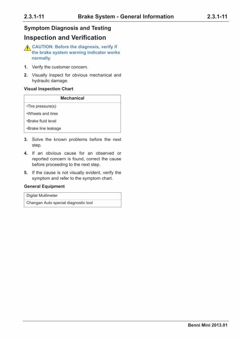
Benni Mini 2013.01
2.3.1-11 2.3.1-11Brake System - General Information
Symptom Diagnosis and Testing
Inspection and Verification
CAUTION: Before the diagnosis, verify if
the brake system warning indicator works
normally.
1. Verify the customer concern.
2. Visually inspect for obvious mechanical and
hydraulic damage.
Visual Inspection Chart
3. Solve the known problems before the next
step.
4. If an obvious cause for an observed or
reported concern is found, correct the cause
before proceeding to the next step.
5. If the cause is not visually evident, verify the
symptom and refer to the symptom chart.
General Equipment
Mechanical
•Tire pressure(s)
•Wheels and tires
•Brake fluid level
•Brake line leakage
Digital Multimeter
Changan Auto special diagnostic tool

2.3.1-12
Benni Mini 2013.01
2.3.1-12Brake System - General Information
Symptom Chart
CAUTION: 1. Replace each component carefully since each component may influence the performance
of the brake system and lead to driving danger. Standard components produced by Changan
Automotive Corporation should be used.
2. It is very important to keep the components and the environment clean during the repair of
the brake system.
3. The component must be dismantled if any brake leak is found. If any abnormal condition is
found, install a new component.
4. Wrap the brake lines to prevent any dust, mud or other foreign matters from entering into
the lines when dismantling the brake components.
5. Do not damage or distort the brake lines when dismantling or fixing the brake lines.
6. During the installation of the brake lines or hoses, make sure that they are not distorted or
bent.
7. Keep the brake hoses away from the shock absorber oil and grease.
8. After installing the brake pipe and hoses, make sure that they are not interfered with other
components.
9. Do not stick the brake fluid to the body or paintwork. If the brake fluid leaks on the paint-
work, it should be cleaned immediately.
When a trouble occurs and the brake system operation indicator still works normally, the troubles should
be diagnosed and solved in the following sequence since it is impossible to verify the causes during the
general inspection and Diagnostic Trouble Codes (DTC) are not stored in the control module memory.

Benni Mini 2013.01
2.3.1-13 2.3.1-13Brake System - General Information
Symptom Possible Sources Solutions
Uneven braking force-devia-
tion
•Inconsistent tire thread and
pressure(s)
•Install new tires and adjust the tire
pressure(s).
•The distortion of the brake
pipe and hoses•Install new brake pipe and hoses.
•Brake shoe or brake pad
(crack, distortion or grease
spots)
•Damaged inside lining
•Clean or replace the brake shoe, the
brake pad as well as the inside lining.
Refer to: (2.3.2 Rear Drum
Brake, Removal and Installa-
tion) and (2.3.3 Front Disc
Brake, Removal and Installa-
tion).
•The abnormal wear and dis-
tortion of the front brake disc
•Inspect the front brake disc.
Refer to: Brake Disc Runout and
Thickness Inspection (2.1.3
Brake System - General Infor-
mation, General Procedures).
•The abnormal wear and dis-
tortion of the rear brake drum
•Install a new brake drum.
Refer to: (2.3.2 Rear Drum
Brake, Removal and Installa-
tion).
•Seized brake slave cylinder
or brake caliper
•Repair or install new brake slave cyl-
inders or brake calipers.
Refer to: (2.3.2 Rear Drum
Brake, Removal and Installa-
tion) or (2.3.3 Front Disc Brake,
Removal and Installation).
•Anti-Lock control failure
•Inspect and repair the anti-lock control.
Refer to: (2.3.7 Anti-Lock Con-
trol, Symptom Diagnosis and
Testing).
•Incorrect wheel alignment •Aligning the wheels

2.3.1-14
Benni Mini 2013.01
2.3.1-14Brake System - General Information
Shaking or vibrating occurs
when applying the brake
•The brake shoe or the brake
pad is worn or damaged or
adhesive with grease.
•Install new brake shoes or brake
pads.
Refer to: (2.3.2 Rear Drum
Brake, Removal and Installa-
tion) or (2.3.3 Front Disc Brake,
Removal and Installation).
•The abnormal wear and dis-
tortion of the front brake disc
•Install new front brake discs.
Refer to: Brake Disc Runout and
Thickness Inspection (2.1.3
Brake System - General Infor-
mation, General Procedures).
•The abnormal wear, distorted
circle and distortion of the
rear brake drum.
•Install a new brake drum.
Refer to: (2.3.2 Rear Drum
Brake, Removal and Installa-
tion).
•The brake caliper mounting
bolts are loosening.
•Tighten the brake caliper mounting
bolts.
•Insufficient lubrication of the
sliding components•Fill lubrication if necessary.
•The loosening or loss of the
wheel hub bolts•Tighten or install new wheel hub bolts.
Symptom Possible Sources Solutions
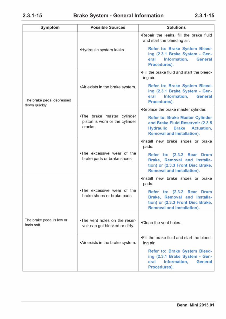
Benni Mini 2013.01
2.3.1-15 2.3.1-15Brake System - General Information
The brake pedal depressed
down quickly
•Hydraulic system leaks
•Repair the leaks, fill the brake fluid
and start the bleeding air.
Refer to: Brake System Bleed-
ing (2.3.1 Brake System - Gen-
eral Information, General
Procedures).
•Air exists in the brake system.
•Fill the brake fluid and start the bleed-
ing air.
Refer to: Brake System Bleed-
ing (2.3.1 Brake System - Gen-
eral Information, General
Procedures).
•The brake master cylinder
piston is worn or the cylinder
cracks.
•Replace the brake master cylinder.
Refer to: Brake Master Cylinder
and Brake Fluid Reservoir (2.3.5
Hydraulic Brake Actuation,
Removal and Installation).
•The excessive wear of the
brake pads or brake shoes
•Install new brake shoes or brake
pads.
Refer to: (2.3.2 Rear Drum
Brake, Removal and Installa-
tion) or (2.3.3 Front Disc Brake,
Removal and Installation).
The brake pedal is low or
feels soft.
•The excessive wear of the
brake shoes or brake pads
•Install new brake shoes or brake
pads.
Refer to: (2.3.2 Rear Drum
Brake, Removal and Installa-
tion) or (2.3.3 Front Disc Brake,
Removal and Installation).
•The vent holes on the reser-
voir cap get blocked or dirty.•Clean the vent holes.
•Air exists in the brake system.
•Fill the brake fluid and start the bleed-
ing air.
Refer to: Brake System Bleed-
ing (2.3.1 Brake System - Gen-
eral Information, General
Procedures).
Symptom Possible Sources Solutions

2.3.1-16
Benni Mini 2013.01
2.3.1-16Brake System - General Information
The brake lockup occurs
when slightly depressing the
brake.
•Incorrect tire pressure(s) •Adjust the tire pressure(s).
•Tire wear •Replace the tire.
•Incorrect installation of the
brake shoes or brake pads
•Install new brake shoes or brake
pads.
Refer to: (2.3.2 Rear Drum
Brake, Removal and Installa-
tion) or (2.3.3 Front Disc Brake,
Removal and Installation).
•Anti-Lock control failure
•Inspect and repair the anti-lock control.
Refer to: (2.3.7 Anti-Lock Con-
trol, Symptom Diagnosis and
Testing).
Depress the pedal and hold it,
it would go down slowly.
•Leaks or air in the brake sys-
tem
•Repair the leaks, fill the brake fluid
and start the bleeding air.
Refer to: Brake System Bleed-
ing (2.3.1 Brake System - Gen-
eral Information, General
Procedures).
•Brake master cylinder trouble
•Refer to this section to inspect the
brake master cylinder, install a new
master cylinder if any trouble is
found.
Refer to: (2.3.5 Hydraulic Brake
Actuation, Removal and Instal-
lation).
Long brake pedal travel
•The excessive wear of the
brake pads or brake shoes
•Install new brake shoes or brake
pads.
Refer to: (2.3.2 Rear Drum
Brake, Removal and Installa-
tion) or (2.3.3 Front Disc Brake,
Removal and Installation).
•Rear wheel brake clearance
automatic adjustment mal-
function
•Repair the manual adjustment func-
tion
Symptom Possible Sources Solutions

Benni Mini 2013.01
2.3.1-17 2.3.1-17Brake System - General Information
Brake drag
•Parking brake is functioning
when the hand brake has not
been completely released
yet.
•Release the hand brake.
•Seized brake caliper or brake
slave cylinder
•Repair or install new brake slave cyl-
inders or brake calipers.
Refer to: (2.3.2 Rear Drum
Brake, Removal and Installa-
tion) or (2.3.3 Front Disc Brake,
Removal and Installation).
•Seized brake pads or brake
shoes
•Repair or install new brake pads or
brake shoes.
Refer to: (2.3.2 Rear Drum
Brake, Removal and Installa-
tion) or (2.3.3 Front Disc Brake,
Removal and Installation).
•Seized parking brake cable.
•Install new parking brake cables.
Refer to: (2.3.2 Rear Drum
Brake, Removal and Installa-
tion).
•Seized vacuum booster •Adjust the length of the brake booster
actuating rod or install a new vacuum
booster.
Refer to: (2.3.6 Boost Booster,
Removal and Installation).
•Brake pedal free travel (Insuf-
ficiency)
Poor efficiency of boosting
brake
•Leaks in the air intake system
•Inspect the air intake system for its
vacuum level and repair it if neces-
sary.
Refer to: (3.1.5 Air Intake Sys-
tem, General Procedures)
•The vacuum boosting hose
leaks.
Refer to: Vacuum Booster
Inspection (2.3.1 Brake System -
General Information, General
Procedures).
•Vacuum boosting hose one-
way valve failure
Symptom Possible Sources Solutions
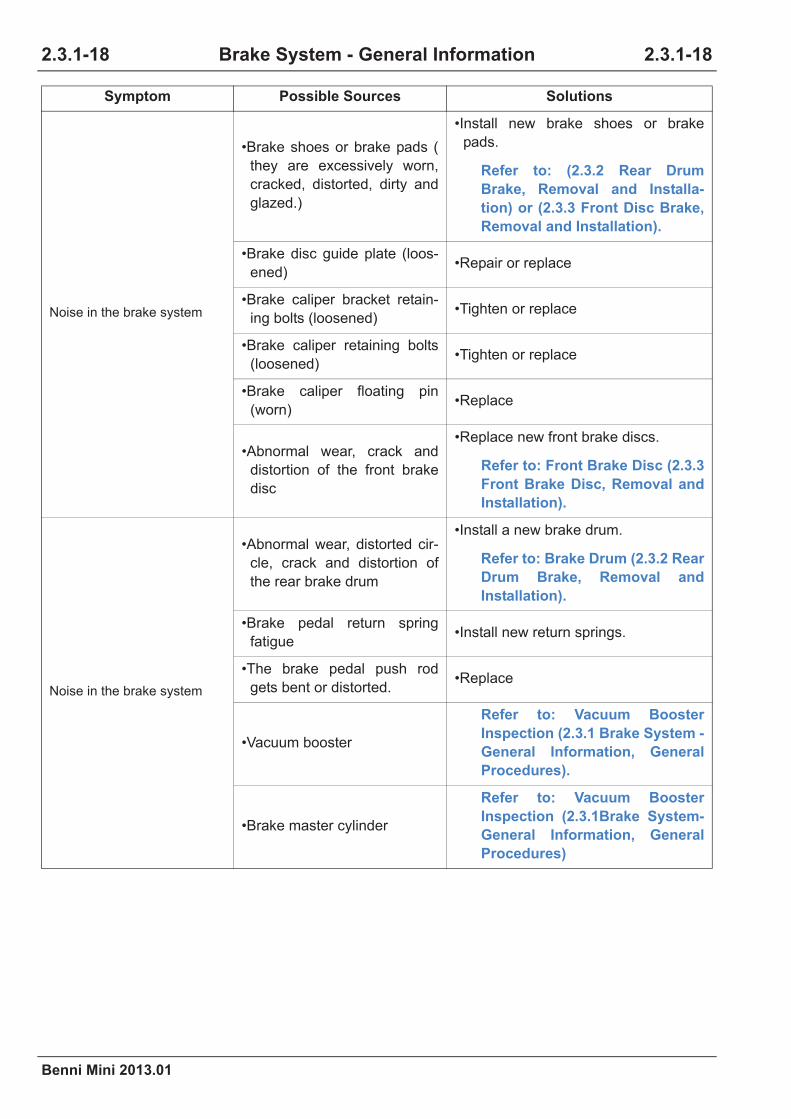
2.3.1-18
Benni Mini 2013.01
2.3.1-18Brake System - General Information
Noise in the brake system
•Brake shoes or brake pads (
they are excessively worn,
cracked, distorted, dirty and
glazed.)
•Install new brake shoes or brake
pads.
Refer to: (2.3.2 Rear Drum
Brake, Removal and Installa-
tion) or (2.3.3 Front Disc Brake,
Removal and Installation).
•Brake disc guide plate (loos-
ened)•Repair or replace
•Brake caliper bracket retain-
ing bolts (loosened)•Tighten or replace
•Brake caliper retaining bolts
(loosened)•Tighten or replace
•Brake caliper floating pin
(worn)•Replace
•Abnormal wear, crack and
distortion of the front brake
disc
•Replace new front brake discs.
Refer to: Front Brake Disc (2.3.3
Front Brake Disc, Removal and
Installation).
Noise in the brake system
•Abnormal wear, distorted cir-
cle, crack and distortion of
the rear brake drum
•Install a new brake drum.
Refer to: Brake Drum (2.3.2 Rear
Drum Brake, Removal and
Installation).
•Brake pedal return spring
fatigue•Install new return springs.
•The brake pedal push rod
gets bent or distorted.•Replace
•Vacuum booster
Refer to: Vacuum Booster
Inspection (2.3.1 Brake System -
General Information, General
Procedures).
•Brake master cylinder
Refer to: Vacuum Booster
Inspection (2.3.1Brake System-
General Information, General
Procedures)
Symptom Possible Sources Solutions

Benni Mini 2013.01
2.3.1-19 2.3.1-19Brake System - General Information
Uneven Brake - Deviation Diagnosis
Test Condition Details/Results/Actions
1. Road test the vehicles
A.Carry out the road test.
B.Inspect for brake deviation.
Does the brake deviation exist?
Y
Go to step 2.
N
Vehicle is normal.
2. Inspect the tire tread and the tire pressure(s)
A.Inspect if the tire tread is the same.
B.Inspect if the tire pressure is normal.
Is the inspection normal?
Y
Go to step 3.
N
Install new tires and adjust the tire pressure(s).
3. Inspect the brake shoe or brake pad
A.Inspect if the brake shoe is oil leaking or unusually
worn.
B.Inspect the brake pad or the inner lining is unusually
worn.
Unusual wear or oil leaking?
Y
Clean or replace the brake shoe or brake pad.
Refer to: (2.3.2 Rear Drum Brake, Removal
and Installation) and (2.3.3 Front Disc
Brake, Removal and Installation).
N
Go to step 4.
4. Inspect the front brake disc
A.Inspect if the front brake disc is unusually worn,
distorted or deformed.
Is the inspection normal?
N
Replace new front brake discs.
Refer to: Front Brake Disc (2.3.3 Front
Brake Disc, Removal and Installation).
Y
Go to step 5.

2.3.1-20
Benni Mini 2013.01
2.3.1-20Brake System - General Information
5. Inspect the rear brake drum
A.Inspect if the rear brake drum is unusually worn, or
deformed.
Is the inspection normal?
N
Install a new brake drum.
Refer to: (2.3.2 Rear Drum Brake, Removal
and Installation).
Y
Go to step 6.
6. Inspect the brake slave cylinder or the brake caliper
A.Inspect if the brake slave cylinder or the brake
caliper is seized.
Is the inspection normal?
N
Repair or install new brake slave cylinders or brake
calipers.
Refer to: (2.3.2 Rear Drum Brake, Removal
and Installation) or (2.3.3 Front Disc
Brake, Removal and Installation).
Y
Go to step 7.
7. Inspect the brake pipe
A.Inspect if the brake hard pipe, hose is distorted or
deformed.
Is the inspection normal?
Y
Install new brake pipe and hoses.
N
Go to step 8.
8. Inspect the anti-lock control
A.Inspect the anti-lock control for failure.
Is the inspection normal?
Y
Inspect and repair the anti-lock control.
Refer to: (2.3.7 Anti-Lock Control, Symp-
tom Diagnosis and Testing).
N
Go to step 9.
Test Condition Details/Results/Actions
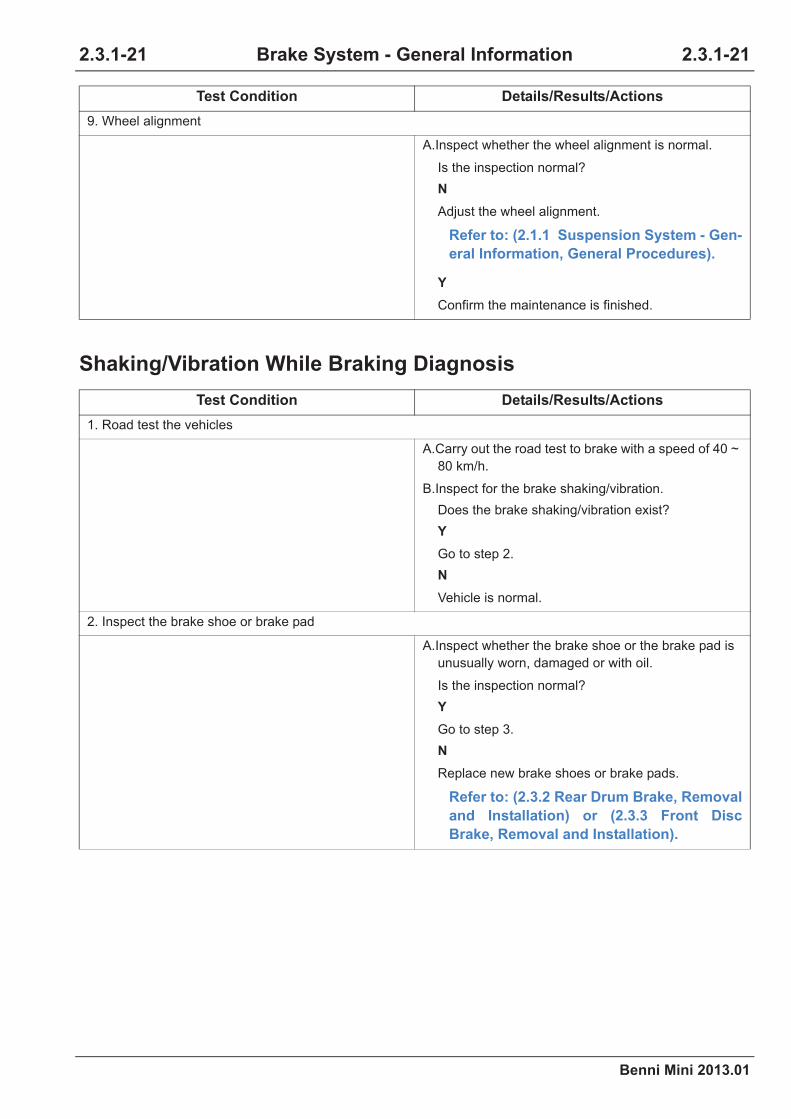
Benni Mini 2013.01
2.3.1-21 2.3.1-21Brake System - General Information
Shaking/Vibration While Braking Diagnosis
9. Wheel alignment
A.Inspect whether the wheel alignment is normal.
Is the inspection normal?
N
Adjust the wheel alignment.
Refer to: (2.1.1 Suspension System - Gen-
eral Information, General Procedures).
Y
Confirm the maintenance is finished.
Test Condition Details/Results/Actions
1. Road test the vehicles
A.Carry out the road test to brake with a speed of 40 ~
80 km/h.
B.Inspect for the brake shaking/vibration.
Does the brake shaking/vibration exist?
Y
Go to step 2.
N
Vehicle is normal.
2. Inspect the brake shoe or brake pad
A.Inspect whether the brake shoe or the brake pad is
unusually worn, damaged or with oil.
Is the inspection normal?
Y
Go to step 3.
N
Replace new brake shoes or brake pads.
Refer to: (2.3.2 Rear Drum Brake, Removal
and Installation) or (2.3.3 Front Disc
Brake, Removal and Installation).
Test Condition Details/Results/Actions

2.3.1-22
Benni Mini 2013.01
2.3.1-22Brake System - General Information
3. Inspect the front brake disc
A.Inspect if the front brake disc is unusually worn,
distorted or deformed.
Is the inspection normal?
N
Install new front brake discs.
Refer to: Front Brake Disc (2.3.3 Front
Brake Disc, Removal and Installation).
Y
Go to step 4.
4. Inspect the rear brake drum
A.Inspect if the rear brake drum is unusually worn, out
of round or deformed.
Is the inspection normal?
N
Replace a new brake drum.
Refer to: (2.3.2 Rear Drum Brake, Removal
and Installation).
Y
Go to step 5.
5. Inspect the brake slave cylinder or the brake caliper
A.Inspect whether the brake caliper bolts is loosen.
B.Inspect if the sliding parts lack of lubrication.
C.The loosening or loss of the wheel hub bolts.
Is the inspection normal?
N
Fasten the bolts for the brake caliper; lubricate the
sliding parts; fasten or replace the hub bolts.
Y
Confirm the maintenance is finished.
Test Condition Details/Results/Actions

Benni Mini 2013.01
2.3.1-23 2.3.1-23Brake System - General Information
Brake Pedal Go Down Quickly Diagnosis
Test Condition Details/Results/Actions
1. Road test the vehicles
A.Carry out the road test, and depress the brake
pedal.
B.Inspect if the action force on the pedal is normal.
Is the action force on the pedal normal?
Y
Vehicle is normal.
N
Go to step 2.
2. Inspect the brake fluid level
A.Inspect the brake fluid reservoir level.
Is it normal?
Y
Go to step 3.
N
Inspect if there is leaking at the sealing of the reser-
voir pipe.
Refer to: (2.1.1 Brake System-General
Information, General Procedures).
3. Brake system pressurizing
A.Depress the brake pedal quickly for five times.
Does the pedal height increase and hold?
Y
Inspect the parking brake and adjust it if necessary.
Refer to: Parking Brake Cable Adjustment
(2.3.4 Parking Brake and Actuation, Gen-
eral Procedures).
In case the fault still exists, bleed the brake system.
Refer to: Brake System Bleeding (2.3.1
Brake System - General Information, Gen-
eral Procedures).
N
Go to step 4.
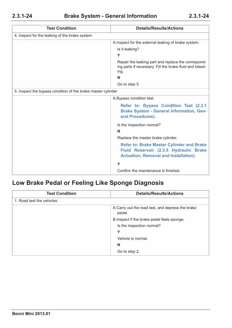
2.3.1-24
Benni Mini 2013.01
2.3.1-24Brake System - General Information
Low Brake Pedal or Feeling Like Sponge Diagnosis
4. Inspect for the leaking of the brake system
A.Inspect for the external leaking of brake system.
Is it leaking?
Y
Repair the leaking part and replace the correspond-
ing parts if necessary. Fill the brake fluid and bleed-
ing.
N
Go to step 5.
5. Inspect the bypass condition of the brake master cylinder
A.Bypass condition test.
Refer to: Bypass Condition Test (2.3.1
Brake System - General Information, Gen-
eral Procedures).
Is the inspection normal?
N
Replace the master brake cylinder.
Refer to: Brake Master Cylinder and Brake
Fluid Reservoir (2.3.5 Hydraulic Brake
Actuation, Removal and Installation).
Y
Confirm the maintenance is finished.
Test Condition Details/Results/Actions
1. Road test the vehicles
A.Carry out the road test, and depress the brake
pedal.
B.Inspect if the brake pedal feels sponge.
Is the inspection normal?
Y
Vehicle is normal.
N
Go to step 2.
Test Condition Details/Results/Actions

Benni Mini 2013.01
2.3.1-25 2.3.1-25Brake System - General Information
2. Inspect the brake fluid level.
A.Inspect the brake fluid reservoir level.
Is it normal?
Y
Go to step 3.
N
Inspect if there is leaking at the sealing of the reser-
voir pipe.
Refer to: (2.1.1 Brake System - General
Information, General Procedures).
3. Inspect the vent hole on the reservoir cover
A.Inspect if the vent hole is blocked or dirty.
Blocked or dirty?
Y
Clean the cover.
N
Go to step 4.
4. Brake system bleeding
A.Inspect the air of the brake system.
Does air exist in the brake system?
Y
Brake System Bleeding.
Refer to: Brake System Bleeding (2.3.1
Brake System - General Information, Gen-
eral Procedures).
N
Go to step 5.
5. Inspect the front wheel hub retaining nut
A.Inspect if the nuts are loosening.
Is the inspection normal?
N
Replace the nuts and fasten.
Y
Inspect the parking brake and adjust it.
Refer to: Parking Brake Cable Adjustment
(2.3.4 Parking Brake and Actuation, Gen-
eral Procedures).
Comfirm the maintenance is finished.
Test Condition Details/Results/Actions

2.3.1-26
Benni Mini 2013.01
2.3.1-26Brake System - General Information
Brake Lock While Slightly Depress the Brake Diagnosis
Test Condition Details/Results/Actions
1. Road test the vehicles
A.Carry out the road test, and depress the brake
pedal.
B.Inspect for the brake locking.
Is the inspection normal?
Y
Vehicle is normal.
N
Go to step 2.
2. Inspect the tire tread and the tire pressure(s)
A.Inspect if the tires are excessively worn or the tire
pressure is abnormal.
Is it normal?
Y
Go to step 3.
N
Replace the tire.
Refer to: Wheels and Tires (2.1.4 Wheels
and Tires, Removal and Installation).
3. Inspect the brake shoe or brake pad
A.Inspect if the brake shoe or pad is correctly installed
or polluted by oil or excessively worn.
Is it normal?
Y
Go to step 4.
N
Install new brake shoes or brake pads.
Refer to: (2.3.2 Rear Drum Brake, Removal
and Installation) or (2.3.3 Front Disc
Brake, Removal and Installation).
4. Inspect the anti-lock control
A.Inspect the anti-lock control for failure.
Is the inspection normal?
Y
Go to step 5.
N
Inspect and repair the anti-lock control.
Refer to: (2.3.7 Anti-Lock Control, Symp-
tom Diagnosis and Testing).

Benni Mini 2013.01
2.3.1-27 2.3.1-27Brake System - General Information
Depress the Brake Pedal and Hold It Down In Depressed Position,
and the Pedal Eases Down Slowly Diagnosis
5. Inspect the vacuum booster
A.Inspect if the brake booster is normal.
Is the inspection normal?
Y
Go to step 6.
N
Replace the brake booster.
Refer to: Brake Booster (2.3.7 Booster
brake, Removal and Installation).
6. Inspect the brake slave cylinder or the brake caliper
A.Inspect if the sliding parts lack of lubrication.
Lack of lubrication?
Y
Lubricate the sliding parts.
N
Confirm the maintenance is finished.
Test Condition Details/Results/Actions
1. Inspect if the fault exists
A.Depress the brake pedal and keep it, and inspect if
the pedal slowly goes down.
Is the inspection normal?
Y
Vehicle is normal.
N
Go to step 2.
2. Inspect the brake fluid level
A.Inspect the brake fluid reservoir level.
Is it normal?
Y
Go to step 5.
N
Go to step 3.
Test Condition Details/Results/Actions

2.3.1-28
Benni Mini 2013.01
2.3.1-28Brake System - General Information
3. Inspect for the leaking of the brake system
A.Inspect for the external leaking of brake system.
Is it leaking?
Y
Repair the leaking part and replace the correspond-
ing parts if necessary. Fill the brake fluid and bleed.
N
Go to step 4.
4. Inspect for the air of brake system
A.Inspect the air of the brake system.
Does air exist in the brake system?
Y
Brake System Bleeding.
Refer to: Brake System Bleeding (2.3.1
Brake System - General Information, Gen-
eral Procedures).
N
Go to step 5.
5. Inspect the brake master cylinder
A.Inspect if the brake master cylinder is normal.
Is it normal?
N
Replace the master brake cylinder.
Refer to: Brake Master Cylinder and Brake
Fluid Reservoir (2.3.5 Hydraulic Brake
Actuation, Removal and Installation).
Y
Confirm the maintenance is finished.
Test Condition Details/Results/Actions

Benni Mini 2013.01
2.3.1-29 2.3.1-29Brake System - General Information
Brake Drag Diagnosis
Test Condition Details/Results/Actions
1. Inspect the parking brake
A.Release the parking brake handle and inspect if the
parking brake is completely released.
Is it normal?
Y
Go to step 2.
N
Inspect the parking brake cable seized and adjust
the parking brake.
Refer to: Parking Brake Cable Adjustment
(2.3.4 Parking Brake and Actuation, Gen-
eral Procedures).
2. Inspect the brake caliper or the brake slave cylinder
A.Inspect if the brake caliper or the brake slave
cylinder is seized.
Is it normal?
Y
Go to step 3.
N
Replace the brake caliper.
Refer to: Brake Caliper (2.3.3 Front Disc
Brake, Removal and Installation).
Replace the brake slave cylinder.
Refer to: Brake Slave Cylinder (2.3.4 Rear
Drum Brake, Removal and Installation).
3. Inspect the brake pad or the brake shoe
A.Inspect if the brake pad or the brake shoe is seized.
Is it normal?
Y
Go to step 4.
N
Replace the brake pad.
Refer to: Brake Pad (2.3.3 Front Disc
Brake, Removal and Installation).
Install new brake shoes.
Refer to: Brake Shoe (2.3.4 Rear Drum
Brake, Removal and Installation).

2.3.1-30
Benni Mini 2013.01
2.3.1-30Brake System - General Information
Test Condition Details/Results/Actions
4. Inspect the brake booster
A.Inspect if the brake booster is seized.
Is it normal?
Y
Go to step 5.
N
Adjust the length of the brake booster push rod or
replace a new brake booster.
Refer to: Brake Booster (2.3.6 Booster
Brake, Removal and Installation).
5. Inspect the free travel of the brake pedal
A.Inspect if the free travel of the brake pedal is normal.
Is it normal?
N
Adjust the length of the push rod of vacuum booster.
Y
Confirm the maintenance is finished.

Benni Mini 2013.01
2.3.2-1 2.3.2-1Rear Drum Brake
Specification
Material Specifications
Rear Drum Brake Specification
WARNING: When the discard thickness has been reached, install a new brake drum. When
the discard thickness has not been reached, the brake drum should go through a polishing
treatment with much care.
Torque Specifications
Item Specification
Brake fluid HZY4
Rear Drum Brake Specification
New brake drum nominal diameter 180 mm
Brake drum discard diameter 182 mm
Brake shoe plate width 30 mm
Brake slave cylinder hole diameter 17.46(ABS) 15.87(non-ABS) mm
New primary shoe friction lining surface thickness 4.5 mm
New secondary brake shoe friction lining surface thick-
ness4.5 mm
Brake shoe friction lining surface discard thickness 1.5 mm
Item Nm lb-ft lb-in
Wheel hub retaining nut 220 162 -
Tire nut 85 63 -
Brake slave cylinder retaining bolt 10 - 89
Brake oil hose connector 15 11 -
2.3.2 Rear Drum Brake

2.3.2-2
Benni Mini 2013.01
2.3.2-2Rear Drum Brake
Description and Operation
Brake System
The rear drum brake assembly is of a secondary
shoe design with a single cylinder hydraulic oper-
ation. The two shoes are pressed tightly on the
brake slave cylinder piston and the retaining ful-
crum post support pin by the upper and lower
return springs. The former one is called "primary
shoe", the other toward the rear is called "second-
ary shoe". The brake slave cylinder is single-cyl-
inder design and installed at the top of the bottom
plate. The brake shoe clearance can be adjusted
manually, and the brake shoe plate wear will
increase the pedal travel so it needs manual
adjustment.
Component Description
Brake Shoe
Apply the mechanical output force from the
hydraulic brake slave cylinder to the friction sur-
face of the brake drum.
Brake Drum
By using the mechanical output force applied by
the brake shoes to the friction surface of the
brake drum, slow down the speed of tires and
wheels assembly to brake the vehicle.
Brake Slave Cylinder
Transmit the hydraulic pressure from the brake
master cylinder into mechanical output force
applied to the brake shoes.
Support Pin and Clearance Adjustment
Machinery
Support the brake shoes and manually adjust the
brake clearance.
Brake Shoe Upper and Lower Return
Spring
The two brake shoes are pressed tightly on the
brake slave cylinder piston and the retaining ful-
crum post support pin by with the upper and lower
return springs; when the brake master cylinder
returns, the upper spring enables the brake slave
cylinder piston to return automatically.
Rear Drum Brake Operation
When the brake pedal is depressed, the mechan-
ical output force from the hydraulic brake slave
cylinder piston is applied to the shoes. The brake
slave cylinder moves the two brake shoes out-
wards which move outwards with the retaining
support pin as the supporting point and stop the
wheels through rubbing with the brake drum.
When the wheels move forwards, the front brake
shoes unfold in the brake drum and produce self-
boosting force. When the wheels move back-
wards, the rear brake shoes produce self-boost-
ing force.
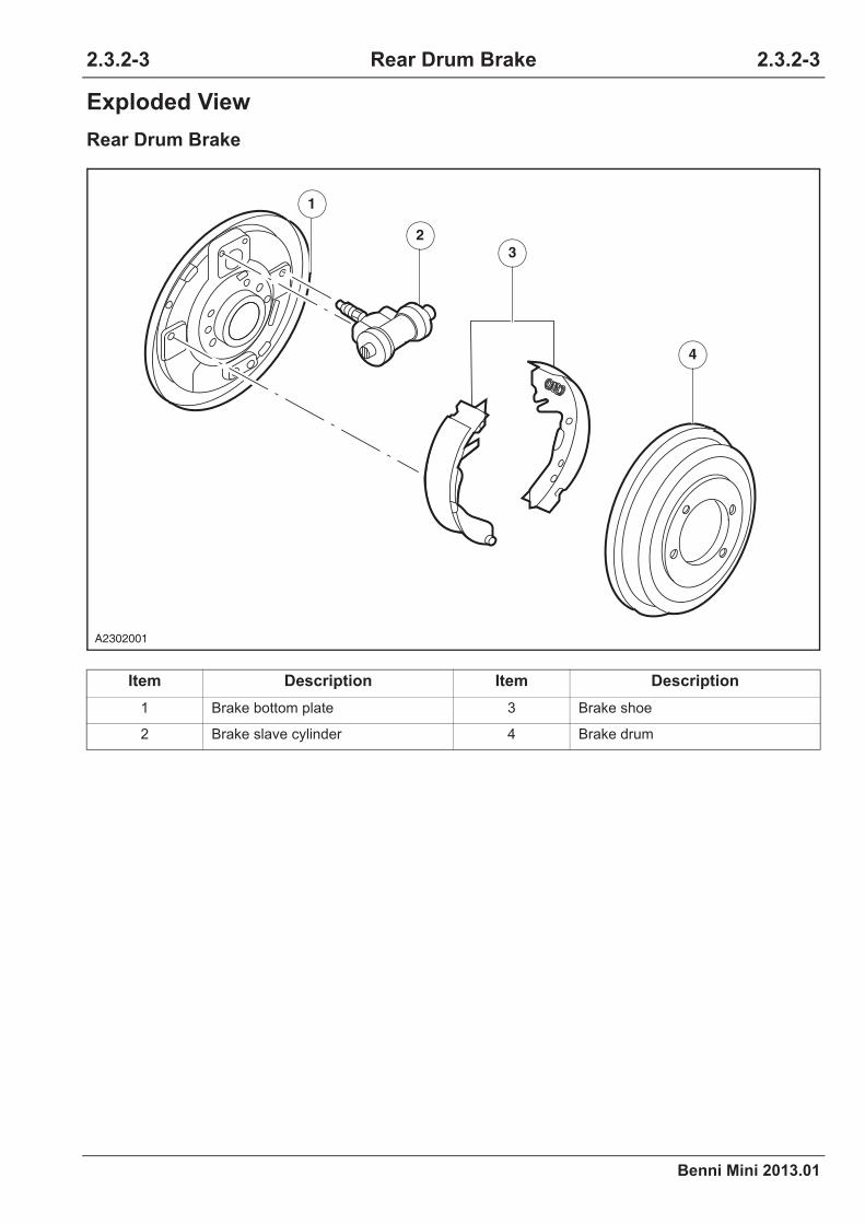
Benni Mini 2013.01
2.3.2-3 2.3.2-3Rear Drum Brake
Exploded View
Rear Drum Brake
Item Description Item Description
1 Brake bottom plate 3 Brake shoe
2 Brake slave cylinder 4 Brake drum
1
2
3
4
A2302001

2.3.2-4
Benni Mini 2013.01
2.3.2-4Rear Drum Brake
Removal and Installation
Brake Drum
Removal
Material
Installation
Item Model
Brake fluid HZY 4
1. Remove the tires.
Refer to: Wheel and Tire (2.1.4 Wheels and
Tires, Removal and Installation).
2. Release the parking brake lever.
3. Lift the vehicle.
Refer to: Lifting (1.1.3 Traction and Lifting,
Description and Operation).
4. Detach the brake drum.
1. To install, reverse the removal procedure.
CAUTION: Adjust the shoe clearance after
the brake drum installation.
A2302004

Benni Mini 2013.01
2.3.2-5 2.3.2-5Rear Drum Brake
Brake Shoe
Removal
Material
Item Model
Grease SAM1C-9107-A
1. Remove the brake drum.
Refer to: Brake Drum (2.3.2 Rear Drum
Brake, Removal and Installation).
2. Remove the brake shoe setting spring.
3. Detach the brake shoe bottom bracket form
the brake shoe, and remove the bottom
return spring.
A2302006
A2302007

2.3.2-6
Benni Mini 2013.01
2.3.2-6Rear Drum Brake
Installation
4. Remove the upper brake shoe return spring
and the jack stay, and detach the brake shoe.
CAUTION: Do not damage the brake slave
cylinder rubber boot when detach the
brake shoe.
5. Remove the parking brake cable, and detach
the brake shoe.
1. Clean, inspect and apply lubricant to the
brake bottom plate contact areas.
A2302008
A2302009
×6
A2302013

Benni Mini 2013.01
2.3.2-7 2.3.2-7Rear Drum Brake
2. Install the parking brake cable.
3. Install the upper brake shoe jack stay and the
return spring.
4. Fix the brake shoe under the bottom bracket
and install the lower return spring.
A2302009
A2302016
A2302017

2.3.2-8
Benni Mini 2013.01
2.3.2-8Rear Drum Brake
5. Install the brake shoe setting spring.
6. Install the brake drum.
7. Adjust the parking brake cable.
Refer to: Parking Brake Cable Adjustment
(2.3.4 Parking Brake and Actuation, Gen-
eral Procedures).
A2302006
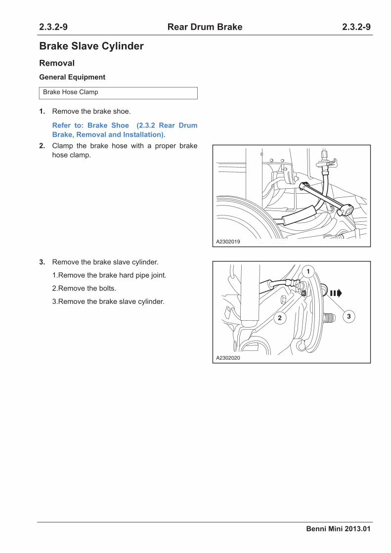
Benni Mini 2013.01
2.3.2-9 2.3.2-9Rear Drum Brake
Brake Slave Cylinder
Removal
General Equipment
Brake Hose Clamp
1. Remove the brake shoe.
Refer to: Brake Shoe (2.3.2 Rear Drum
Brake, Removal and Installation).
2. Clamp the brake hose with a proper brake
hose clamp.
3. Remove the brake slave cylinder.
1.Remove the brake hard pipe joint.
2.Remove the bolts.
3.Remove the brake slave cylinder.
A2302019
1
2 3
A2302020

2.3.2-10
Benni Mini 2013.01
2.3.2-10Rear Drum Brake
Installation
1. Install the brake slave cylinder.
1.Install the brake slave cylinder bolts.
Torque: 10 Nm
2.Install the brake hard pipe joint.
Torque: 15 Nm
2. Install the brake hose clamp.
3. Brake system bleeding.
Refer to: Brake System Bleeding (2.3.1
Brake System - General Information, Gen-
eral Procedures).
1
2
A2302021

Benni Mini 2013.01
2.3.2-11 2.3.2-11Rear Drum Brake
Brake Bottom Plate
Removal
Installation
1. To install, reverse the removal procedure.
1. Remove the rear wheel bearing.
Refer to: Rear Wheel Bearing (2.1.3 Rear
Suspension, Removal and Installation).
2. Remove the brake shoe.
Refer to: Brake Shoe (2.3.2 Rear Drum
Brake, Removal and Installation).
3. Remove the brake slave cylinder.
Refer to: Brake Slave Cylinder (2.3.2 Rear
Drum Brake, Removal and Installation).
4. Detach the parking brake cable.
1.Remove the retaining clamp.
2.Detach the brake cable.
5. Remove the brake bottom plate.
1.Remove the four retaining bolts on the
brake bottom plate and detach the brake bot-
tom plate.
Torque: 42.5 Nm
1
2
A2302022
×4
A2302023


Benni Mini 2013.01
2.3.3-1 2.3.3-1Front Disc Brake
Specifications
Material Specifications
Front Disc Brake Specification
CAUTION: When the discard thickness has been reached, install a new brake disc. When the
discard thickness has not been reached, the brake disc should go through a polishing treat-
ment with much care.
Torque Specifications
Item Specification
Brake fluid HZY4
Front Disc Brake Specification
Brake disc diameter 236mm
Brake disc normal thickness 12.5 mm
Brake disc discard thickness 9.7 mm
Maximum brake disc runou (Installed) 0.1 mm
Maximum brake disc thickness variation 0.015 mm
Brake caliper piston diameter 48mm
Minimum brake friction block thickness 3mm
Item Nm lb-ft lb-in
Tire nut 85 63 -
Brake slave cylinder piston housing bolt 27 20 -
Brake caliper anchor plate bolts 83 61 -
Brake caliper brake hose connector 23 17 -
2.3.3 Front Disc Brake
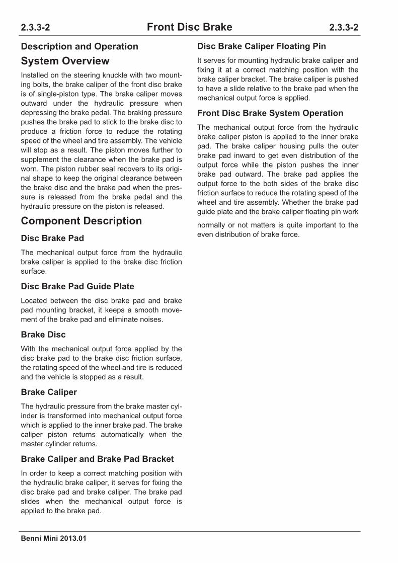
2.3.3-2
Benni Mini 2013.01
2.3.3-2Front Disc Brake
Description and Operation
System Overview
Installed on the steering knuckle with two mount-
ing bolts, the brake caliper of the front disc brake
is of single-piston type. The brake caliper moves
outward under the hydraulic pressure when
depressing the brake pedal. The braking pressure
pushes the brake pad to stick to the brake disc to
produce a friction force to reduce the rotating
speed of the wheel and tire assembly. The vehicle
will stop as a result. The piston moves further to
supplement the clearance when the brake pad is
worn. The piston rubber seal recovers to its origi-
nal shape to keep the original clearance between
the brake disc and the brake pad when the pres-
sure is released from the brake pedal and the
hydraulic pressure on the piston is released.
Component Description
Disc Brake Pad
The mechanical output force from the hydraulic
brake caliper is applied to the brake disc friction
surface.
Disc Brake Pad Guide Plate
Located between the disc brake pad and brake
pad mounting bracket, it keeps a smooth move-
ment of the brake pad and eliminate noises.
Brake Disc
With the mechanical output force applied by the
disc brake pad to the brake disc friction surface,
the rotating speed of the wheel and tire is reduced
and the vehicle is stopped as a result.
Brake Caliper
The hydraulic pressure from the brake master cyl-
inder is transformed into mechanical output force
which is applied to the inner brake pad. The brake
caliper piston returns automatically when the
master cylinder returns.
Brake Caliper and Brake Pad Bracket
In order to keep a correct matching position with
the hydraulic brake caliper, it serves for fixing the
disc brake pad and brake caliper. The brake pad
slides when the mechanical output force is
applied to the brake pad.
Disc Brake Caliper Floating Pin
It serves for mounting hydraulic brake caliper and
fixing it at a correct matching position with the
brake caliper bracket. The brake caliper is pushed
to have a slide relative to the brake pad when the
mechanical output force is applied.
Front Disc Brake System Operation
The mechanical output force from the hydraulic
brake caliper piston is applied to the inner brake
pad. The brake caliper housing pulls the outer
brake pad inward to get even distribution of the
output force while the piston pushes the inner
brake pad outward. The brake pad applies the
output force to the both sides of the brake disc
friction surface to reduce the rotating speed of the
wheel and tire assembly. Whether the brake pad
guide plate and the brake caliper floating pin work
normally or not matters is quite important to the
even distribution of brake force.

Benni Mini 2013.01
2.3.3-3 2.3.3-3Front Disc Brake
Exploded View
Front Disc Brake
Item Description Item Description
1 Brake disc 3 Brake pad
2 Brake caliper
1
2
3
A2303015

2.3.3-4
Benni Mini 2013.01
2.3.3-4Front Disc Brake
Disassembly and Assembly
Brake Caliper
Disassembly
Material
Item Model
Brake fluid HZY 4
1. Pull the brake slave cylinder piston out of the
brake caliper housing by using compressed
air.
CAUTION: If the brake fluid is spilt on the
paintwork, the affected area must be
immediately washed down with cold water.
CAUTION: A wood block or a wood cush-
ion or some cloth is placed between the
brake slave cylinder piston and the brake
caliper housing to prevent damaging the
brake slave cylinder piston.
2. Remove and discard the dust-proof oil seal.
3. Remove and discard the piston oil seal.
4. Inspect the piston and the piston hole for any
damage and wear. Install a new brake caliper
if necessary.
A2303011
A2303012
A2303013

Benni Mini 2013.01
2.3.3-5 2.3.3-5Front Disc Brake
Assembly
1. Use the brake fluid to lubricate the piston
hole, the piston oil seal and the brake caliper.
2. Install a new piston oil seal into the piston
hole.
CAUTION: The piston oil seal must be
installed into the piston hole groove.
3. Install a new dust-proof oil seal on the brake
slave cylinder piston.
4. Assemble the brake slave cylinder piston into
the piston hole.
CAUTION: Do not scratch the piston when
assembling the piston into the piston hole.
A2303013
A2303014
A2303011

2.3.3-6
Benni Mini 2013.01
2.3.3-6Front Disc Brake
Removal and Installation
Brake Pad
Removal
Material
Item Model
Brake fluid HZY 4
1. Remove the tires.
Refer to: Wheel and Tire (2.1.4 Wheels and
Tires, Removal and Installation).
2. Remove the brake slave cylinder.
1.Remove the lower retaining bolts of the
brake slave cylinder.
2.Rotate the brake slave cylinder upwards.
3. Remove the brake pad.
1
2
A2303001
A2303002
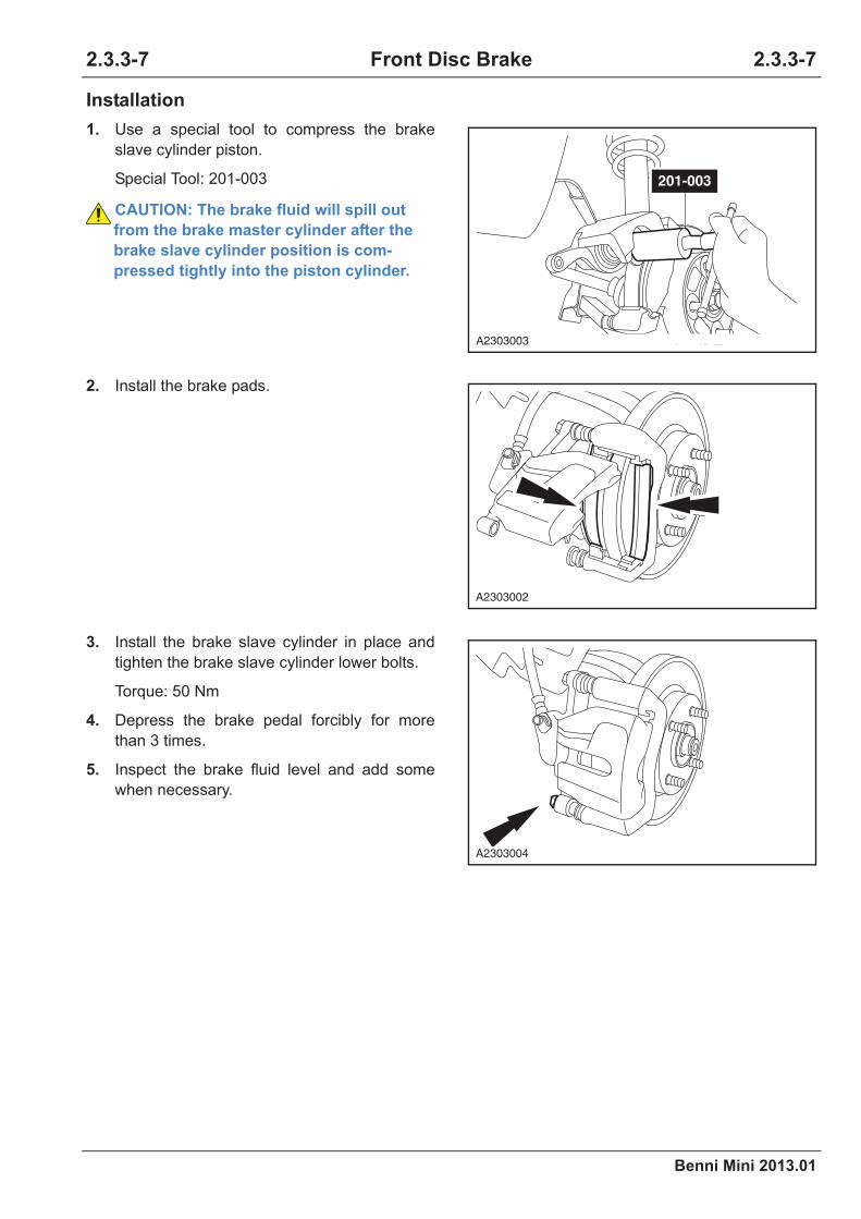
Benni Mini 2013.01
2.3.3-7 2.3.3-7Front Disc Brake
Installation
1. Use a special tool to compress the brake
slave cylinder piston.
Special Tool: 201-003
CAUTION: The brake fluid will spill out
from the brake master cylinder after the
brake slave cylinder position is com-
pressed tightly into the piston cylinder.
2. Install the brake pads.
3. Install the brake slave cylinder in place and
tighten the brake slave cylinder lower bolts.
Torque: 50 Nm
4. Depress the brake pedal forcibly for more
than 3 times.
5. Inspect the brake fluid level and add some
when necessary.
201-003
A2303003
A2303002
A2303004

2.3.3-8
Benni Mini 2013.01
2.3.3-8Front Disc Brake
Brake Caliper
Removal
General Equipment
Installation
Brake hose clamp
1. Detach the brake hose from the front strut.
2. Clamp the brake hose with a proper brake
hose clamp.
3. Remove the brake caliper.
1.Remove the brake hose retaining bolt.
Torque: 23 Nm
2.Remove the brake caliper upper and lower
retaining bolts.
Torque: 83 Nm
CAUTION: If the brake fluid is spilt on the
paintwork, the affected area must be
immediately washed down with cold
water.
CAUTION: Seal the brake hose to prevent
the loss of fluid and the foreign materials
from entering.
1. To install, reverse the removal procedure.
2. Brake system bleeding.
Refer to: Brake System Bleeding (2.3.1
Brake System - General Information, Gen-
eral Procedures).
A2303005
12
2
A2303006
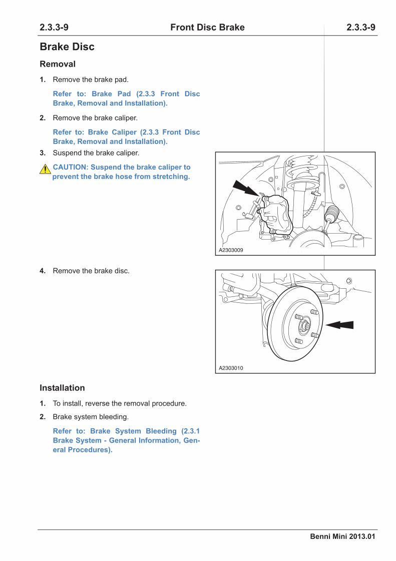
Benni Mini 2013.01
2.3.3-9 2.3.3-9Front Disc Brake
Brake Disc
Removal
Installation
1. Remove the brake pad.
Refer to: Brake Pad (2.3.3 Front Disc
Brake, Removal and Installation).
2. Remove the brake caliper.
Refer to: Brake Caliper (2.3.3 Front Disc
Brake, Removal and Installation).
3. Suspend the brake caliper.
CAUTION: Suspend the brake caliper to
prevent the brake hose from stretching.
4. Remove the brake disc.
1. To install, reverse the removal procedure.
2. Brake system bleeding.
Refer to: Brake System Bleeding (2.3.1
Brake System - General Information, Gen-
eral Procedures).
A2303009
A2303010


Benni Mini 2013.01
2.3.4-1 2.3.4-1Parking Brake and Actuation
Specifications
Torque Specifications
Item Nm lb-ft lb-in
Parking brake cable adjustment nut 4 - 35
Parking brake control nut 23 17 -
2.3.4Parking Brake and Actuation
2.3.4-2
Benni Mini 2013.01
2.3.4-2Parking Brake and Actuation
Description and Operation
System Overview
Parking braking is actuated by the rear brake.
The parking brake system consists of parking
brake, manual braking control mechanism and
parking brake cable.
Parking brake system is a mechanical system
controlling the rear drum brake through a parking
brake lever. The system is actuated by pulling up
the parking brake lever which allows the rear
drum brake shoes (primary shoes and secondary
shoes) to expand outward to apply parking brake
through the cables. The parking brake indicator in
the instrument cluster is turned on when the
parking brake lever is pulled up and connected to
the ignition switch. Pull up the lever and depress
the button on it. Put down lever to release the
parking brake and the parking brake indicator in
the instrument cluster is turned off.

Benni Mini 2013.01
2.3.4-3 2.3.4-3Parking Brake and Actuation
General Procedures
Parking Brake Cable
Adjustment
CAUTION: Inspect the rear drum brake
shoes for not excessive wear before the
adjustment.
1. Remove the console.
Refer to: Console (5.1.6 Instrument Panel
and Console).
2. Release the parking brake lever.
3. Loosen the adjustment nut.
4. Repeat depressing the brake pedal 6 times
and then release it.
5. Draw back the parking cable with all strength
4 times and then adjust the cable.
1.Pull up the parking brake lever with 4
creaks.
2.Tighten the adjustment nut.
Torque: 4 Nm
6. Test the parking brake for normal operation.
7. Install the parking brake control cover.
A2304007
A2304007

2.3.4-4
Benni Mini 2013.01
2.3.4-4Parking Brake and Actuation
Symptom Diagnosis and Testing
Inspection and Verification
1. Verify the customer concerns.
2. Visually inspect for any obvious signs of
mechanical damage and hydraulic troubles.
Visual Inspection Chart
3. Solve the known problems before the next
step.
4. If an obvious cause for an observed or
reported concern is found, correct the
problem before proceeding to the next step.
5. If the cause is not visually evident, verify the
symptom and refer to the Symptom Chart.
General Equipments
Mechanical
•Tire pressure (s)
•Wheel and tire
•Brake fluid level
•Brake line leak
Digital Multimeter

Benni Mini 2013.01
2.3.4-5 2.3.4-5Parking Brake and Actuation
Symptom Chart
Symptom Possible Sources Action
Parking brake failure
Poor parking brake force
•Excessive parking brake lever
travel
Refer to: Parking Brake Cable
Adjustment (2.3.4 Parking
Brake and Actuation, General
Procedures).
•Left and right parking brake cable
(seized and cracked)
•Repair or remove new parking brake
cables.
Refer to: Parking Brake Cable
(2.3.4 Parking Brake and Actua-
tion, Removal and Installation).
•Cable equalizer (lossened,
crakced, distorted)•Install a new cable equalizer.
•Rear brake shoes (worn to the
limit)
•Install new brake shoes.
Refer to: Brake Shoe (2.3.2 Rear
Drum Brake, Removal and
Installation).
•Rear drum brake inner the fulcrum
post and parking control lever
(distorted and cracked)
•Install the fulcrum pin and parking control
lever.
Parking brake can not
release (lag)
•Insufficient parking brake lever
travel
Refer to: Parking Brake Cable
Adjustment (2.3.4 Parking
Brake and Actuation, General
Procedures).
• Left and right parking brake
cables (seized)
•Repair or remove new parking brake
cables.
Refer to: Install New Parking
Brake Cables (2.3.4 Parking
Brake and Actuation, Removal
and Installation).
• Rear brake shoe (seized, cracked
and distorted)
•Repair or install new brake shoes.
Refer to: Brake Shoe (2.3.2 Rear
Drum Brake, Removal and
Installation).
•Rear brake return spring (fatigue
and cracked)•Install new return springs.

2.3.4-6
Benni Mini 2013.01
2.3.4-6Parking Brake and Actuation
Parking Brake Not Work (Failure) Diagnosis/Poor Parking Brake
The parking brake indicator
is turned off when the
ignition switch is
in“ON”position and the
vehicle is under parking
state
•Instrument cluster fuse
•The diagnostic procedures for the switch-
off of the parking warning indicator when
the ignition switch is in ”ON” position and
the vehicle is in parking state.
Refer to: Symptom Chart (4.3.2
Instrument Cluster, Symptom
Diagnosis and Testing).
•Instrument wiring harness
connector
•Instrument power circuit
•nstrument ground circuit
•The wiring harness between the
parking brake warning indicator
switch and instrument cluster
•Parking brake switch
•Instrument cluster
The parking brake indicator
is always on
•Parking brake switch Refer to: Parking Brake Indica-
tor Always On (2.3.4 Parking
Brake and Actuation, Symptom
Diagnosis and Testing).
•The wiring harness between the
parking brake switch and the
instrument (wiring harness
connectors)
•Wiring harness (Instrument clus-
ter assembly-power supply and
ground)
•Instrument cluster
Test Conditions Details/Results/Actions
1. Inspect the travel of the parking brake control lever
A.Inspect if the travel of the parking brake control
lever is normal.
Is it normal?
Y
Go to step 2.
N
Adjust the travel of the parking brake control lever.
Refer to: Parking Brake Cable Adjustment
(2.3.4 Parking Brake and Control, General
Procedures).
Symptom Possible Sources Action
Benni Mini 2013.01
2.3.4-7 2.3.4-7Parking Brake and Actuation
2. Inspect the parking brake cable
A.Inspect the parking brake cable for any damage or
clamping stagnation.
Is it normal?
Y
Go to step 3.
N
Repair or replace the parking brake cable.
Refer to: Parking Brake Cable (2.3.4 Park-
ing Brake and Control, Removal and
Installation).
3. Inspect the thickness of the rear brake shoe
A.Inspect if the thickness of the brake shoe is normal.
Is it normal?
Y
Go to step 4.
N
Replace the brake shoe.
Refer to: Brake Shoe (2.3.2 Rear Drum
Brake, Removal and Installation).
4. Inspect the return spring of the rear brake
A.Inspect if the return spring of the rear drum brake is
normal.
Is it normal?
Y
Confirm the maintenance is finished.
N
Inspect and repair the rear drum brake.
Test Conditions Details/Results/Actions

2.3.4-8
Benni Mini 2013.01
2.3.4-8Parking Brake and Actuation
Parking Brake Not Release (Lag) Diagnosis
Test Conditions Details/Results/Actions
1. Inspect the travel of the parking brake control lever
A.Inspect if the travel of the parking brake control
lever is normal.
Is it normal?
Y
Go to step 2.
N
Adjust the travel of the parking brake control lever.
Refer to: Parking Brake Cable Adjustment
(2.3.4 Parking Brake and Control, General
Procedures).
2. Inspect the parking brake cable
A.Inspect the parking brake cable for any damage or
clamping stagnation.
Is it normal?
Y
Go to step 3.
N
Repair or replace the parking brake cable.
Refer to: Parking Brake Cable (2.3.4 Park-
ing Brake and Control, Removal and
Installation)
3. Inspect the rear brake shoe
,
A.Inspect if the thickness of the brake shoe is normal.
Is it normal?
Y
Go to step 4.
N
Replace the brake shoe.
Refer to: Brake Shoe (2.3.2 Rear drum
brake, Removal and Installation).
4. Inspect the return spring of the rear brake
A.Inspect if the return spring of the rear drum brake is
normal.
Is it normal?
Y
Confirm the maintenance is finished.
N
Inspect and repair the rear drum brake.

Benni Mini 2013.01
2.3.4-9 2.3.4-9Parking Brake and Actuation
Parking Brake Indicator Always On Diagnosis
Test Conditions Details/Results/Actions
1. General inspection
A.Inspect for the brake fluid lack.
Is it normal?
Y
Go to step 2.
N
Inspect and repair the brake fluid level.
2. Inspect the parking brake switch
A.Turn the ignition switch to position "LOCK".
B.Disconnect the brake switch wiring harness
connector S11.
C.Inspect whether the switch is disconnected when
the parking brake lever is put down; and whether
the switch is connected when the parking brake
lever is pulled up.
Are all the conditions above satisfied?
Y
Go to step 3.
N
Inspect and repair the parking brake switch, and
replace it when necessary.

2.3.4-10
Benni Mini 2013.01
2.3.4-10Parking Brake and Actuation
3. Inspect the circuit between the wiring harness connector S11 and P07
,
A.Turn the ignition switch to position "LOCK".
B.Disconnect the instrument cluster wiring harness
connector P07, the wiring harness connector C10
of the brake fluid level sensor, and the wiring
harness connector S11 of the brake switch.
C.Measure the resistance between the terminal 1 of
the brake switch wiring harness connector S11 and
the body ground with a multimeter.
Standard Resistant Value: 10 M or higher
Is the resistant value normal?
Y
Go to step 4.
N
Inspect and repair the failed circuit.
4. Replace the brake fluid level sensor
A.Turn the ignition switch to position "LOCK".
B.Disconnect the wiring harness connector C10 of the
brake fluid level sensor.
C.Inspect whether the brake fluid level sensor is
normal (The two pins shall not be conducted when
the brake fluid level is normal).
Is the brake fluid level sensor normal?
Y
Go to step 5.
N
Replace the brake fluid level sensor.
Test Conditions Details/Results/Actions
S11
1
A2304010
S11
P07
17
1
1 2 16
32
A2304011
1 2
C10
A2304012

Benni Mini 2013.01
2.3.4-11 2.3.4-11Parking Brake and Actuation
5. Inspect the instrument cluster power supply
A.Turn the ignition switch to position "ON" and inspect
the power supply circuit of the terminal 7 of the
wiring harness connector P07 of the instrument
cluster.
Standard Voltage Value: 11~14 V
Is it normal?
Y
Replace the instrument cluster.
Refer to: Instrument Cluster (4.3.2 Instru-
ment Cluster, Removal and Installation).
N
Inspect and repair the instrument cluster circuit.
Test Conditions Details/Results/Actions
17
1 7 16
32
P07
A2304014

2.3.4-12
Benni Mini 2013.01
2.3.4-12Parking Brake and Actuation
Removal and Installation
Parking Brake Control
Removal
1. Remove the console.
Refer to: Console (5.1.6 Instrument Clus-
ter and Console, Removal and Installa-
tion).
2. Release the parking brake lever.
1.Loosen the adjustment nut.
Torque: 4 Nm
2.Adjust the parking brake cable.
3. Remove the parking brake lever retaining
bolt.
Torque: 23 Nm
4. Disconnect the parking brake indicator switch
connector and detach the parking brake lever.
1
2 2
A2304001
×2
A2304002
A2304003
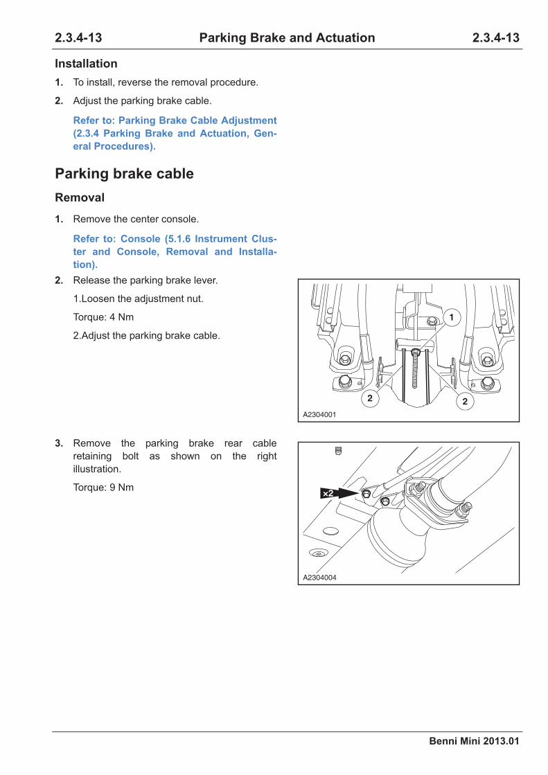
Benni Mini 2013.01
2.3.4-13 2.3.4-13Parking Brake and Actuation
Installation
Parking brake cable
Removal
1. To install, reverse the removal procedure.
2. Adjust the parking brake cable.
Refer to: Parking Brake Cable Adjustment
(2.3.4 Parking Brake and Actuation, Gen-
eral Procedures).
1. Remove the center console.
Refer to: Console (5.1.6 Instrument Clus-
ter and Console, Removal and Installa-
tion).
2. Release the parking brake lever.
1.Loosen the adjustment nut.
Torque: 4 Nm
2.Adjust the parking brake cable.
3. Remove the parking brake rear cable
retaining bolt as shown on the right
illustration.
Torque: 9 Nm
1
2 2
A2304001
×2
A2304004
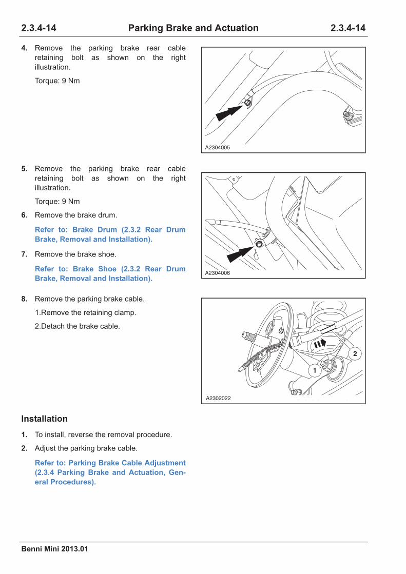
2.3.4-14
Benni Mini 2013.01
2.3.4-14Parking Brake and Actuation
Installation
4. Remove the parking brake rear cable
retaining bolt as shown on the right
illustration.
Torque: 9 Nm
5. Remove the parking brake rear cable
retaining bolt as shown on the right
illustration.
Torque: 9 Nm
6. Remove the brake drum.
Refer to: Brake Drum (2.3.2 Rear Drum
Brake, Removal and Installation).
7. Remove the brake shoe.
Refer to: Brake Shoe (2.3.2 Rear Drum
Brake, Removal and Installation).
8. Remove the parking brake cable.
1.Remove the retaining clamp.
2.Detach the brake cable.
1. To install, reverse the removal procedure.
2. Adjust the parking brake cable.
Refer to: Parking Brake Cable Adjustment
(2.3.4 Parking Brake and Actuation, Gen-
eral Procedures).
A2304005
A2304006
1
2
A2302022

Benni Mini 2013.01
2.3.4-15 2.3.4-15Parking Brake and Actuation
Parking Brake Warning Lamp Switch
Removal
Installation
1. Remove the center console.
Refer to: Console (5.1.6 Instrument Clus-
ter and Console, Removal and Installa-
tion).
2. Removal the switch.
1.Disconnect the switch connector.
2.Remove the switch retaining screw.
3.Detach the switch.
1. To install, reverse the removal procedure.
2. Adjust the parking brake cable.
Refer to: Parking Brake Cable Adjustment
(2.3.4 Parking Brake and Actuation, Gen-
eral Procedures).
2
1
A2304008


Benni Mini 2013.01
2.3.5-1 2.3.5-1Hydraulic Brake Actuation
Specification
Material Specifications
Torque Specifications
Item Specification
Brake fluid HZY4
Item Nm lb-ft lb-in
Brake master cylinder and pipe retaining
nut16 12 -
Brake master cylinder retaining nut 25 18 -
Brake pedal coupling spindle retaining nut 25 18 -
2.3.5 Hydraulic Brake Actuation

2.3.5-2
Benni Mini 2013.01
2.3.5-2Hydraulic Brake Actuation
Description and Operation
System Overview
The vehicle is stopped as the brake pad presses
tightly the brake disc with a mechanical force
transformed from a hydraulic pressure by the
brake slave cylinder to which a hydraulic pressure
that is transformed from a mechanical force from
the brake pedal by the brake master cylinder is
delivered through the brake hard pipes and hoses
after the adjustment of the hydraulic electronic
control unit or proportioning valve.
Component Description
Brake Pedal
The brake system input force is received, ampli-
fied and delivered from the driver.
Brake Pedal Push Rod
Deliver the increased brake pedal input force to
the vacuum booster.
Brake Master Cylinder Reservoir
Brake fluid used for the hydraulic brake system is
installed inside.
Brake Master Cylinder
Transform the mechanical input force into hydrau-
lic output force. The hydraulic output pressure is
distributed into two hydraulic brake tubes from the
master cylinder, providing brake fluid for the diag-
onal wheel brake tubes.
Brake Pipes and Brake Hose
Pass the brake fluid through each component of
the hydraulic brake system.
Brake Slave Cylinder
Transform the hydraulic input pressure into
mechanical output force.
Brake Fluid Low Level Warning Indicator
The instrument cluster turns on the brake fluid low
level warning indicator when it detects the exces-
sive brake fluid low level (The signal circuit is at
electronegative potential) or the parking brake
lever is not released.

Benni Mini 2013.01
2.3.5-3 2.3.5-3Hydraulic Brake Actuation
Removal and Installation
Brake Master Cylinder and Brake Fluid Reservoir
Removal
Material
Item Model
Brake fluid HZY 4
CAUTION: If brake fluid is spilt on the
paintwork, the affected area must be
immediately washed down with cold water.
CAUTION: The reservoir must be clean.
1. Disconnect the brake fluid low level warning
lamp switch connector.
2. Remove the reservoir cap.
3. Drain the brake fluid from the reservoir.
1.Connect one end of a suitable piece of clear
plastic pipe to the system bleeding nozzle
and place the other end into a suitable con-
tainer.
2.Loosen the brake bleeding nozzle.
3.Depress the brake pedal until all the brake
fluid is drained from the brake fluid reservoir.
4.Tighten the brake bleeding nozzle.
CAUTION: Repeat the draining procedure
on the opposite side brake.
1
2
A2305001
2
1
43
A2305002

2.3.5-4
Benni Mini 2013.01
2.3.5-4Hydraulic Brake Actuation
Installation
4. Remove the brake pipe from the brake
master cylinder.
Torque: 16 Nm
5. Remove the brake master cylinder and the
brake fluid reservoir assembly.
1.Remove the retaining nut.
Torque: 25 Nm
2.Take out the brake master cylinder.
1. To install, reverse the removal procedure.
2. Brake system bleeding.
Refer to: Brake System Bleeding (2.3.1
Brake System - General Information, Gen-
eral Procedures).
CAUTION: Make sure that the brake
booster push rod is correctly located
before the installation.
CAUTION: Make sure that the brake mas-
ter cylinder vacuum seals are correctly
located before the installation.
×2
A2305003
A2305004

Benni Mini 2013.01
2.3.5-5 2.3.5-5Hydraulic Brake Actuation
Brake, Clutch and Accelerator Pedal Assembly (MT)
Removal
1. Disconnect the battery negative cable.
Refer to: Battery Inspection (3.1.10 Charg-
ing System, General Procedures).
2. Remove the air cleaner assembly.
3. Release the clutch cable.
Torque: 4 Nm
4. Remove the clutch pedal external firewall
retaining bolts and nuts.
Torque: 25 Nm
5. Disconnect the stop lamp switch connector.
A2305005
A2305006
A2305007

2.3.5-6
Benni Mini 2013.01
2.3.5-6Hydraulic Brake Actuation
6. Remove the throttle cable from the accelerator
pedal.
7. Remove the accelerator pedal from the brake,
clutch and accelerator pedal assembly.
1.Remove the accelerator pedal retaining
snap ring.
2.Detach the accelerator pedal.
8. Detach the clutch cable from the clutch pedal.
9. Remove the brake booster.
1.Remove the brake push rod and brake
pedal retaining clamp, detach the push rod
retaining pin.
2.Remove the four mounting bolts on the
brake booster.
Torque: 25 Nm
A2305008
A2305011
A2305009
2×4
1
A2306002

Benni Mini 2013.01
2.3.5-7 2.3.5-7Hydraulic Brake Actuation
Installation
1. To install, reverse the removal procedure.
10. Remove the five mounting bolts and nuts on
the brake, clutch and accelerator pedal
assembly.
Torque: 25 Nm
11. Detach the brake, clutch and accelerator
pedal assembly.
A2305010
A2305012

2.3.5-8
Benni Mini 2013.01
2.3.5-8Hydraulic Brake Actuation
Brake Pedal Assembly (AT)
Removal
1. Disconnect the battery negative cable.
Refer to: Battery Inspection (3.1.10 Charg-
ing System, General Procedures).
2. Remove the clutch pedal external firewall
retaining bolts and nuts.
Torque: 25 Nm
3. Disconnect the stop lamp switch connector.
4. Remove the accelerator pedal position
sensor.
Refer to: Accelerator Pedal Position Sen-
sor (3.1.13 Electrical control System-ME7,
Removal and Installation).
5. Remove the brake booster.
1.Remove the brake push rod and brake
pedal retaining clamp, detach the push rod
retaining pin.
2.Remove the four mounting bolts on the
brake booster.
Torque: 25 Nm
6. Remove the five mounting bolts and nuts on
the brake pedal assembly.
Torque: 25 Nm
7. Remove the steering column.
Refer to: Steering Column (2.4.4 Steering
Column, Removal and Installation).
A2305006
2×4
1
A2306002
A2305013

Benni Mini 2013.01
2.3.5-9 2.3.5-9Hydraulic Brake Actuation
Installation
1. To install, reverse the removal procedure.
8. Detach the pedal assembly.
A2305014


Benni Mini 2013.01
2.3.6-1 2.3.6-1Power Brake Actuation
Specifications
Torque Specifications
Item Nm lb-ft lb-in
Brake booster retaining bolt 25 18 -
Brake master cylinder retaining bolt 25 18 -
2.3.6 Power Brake Actuation
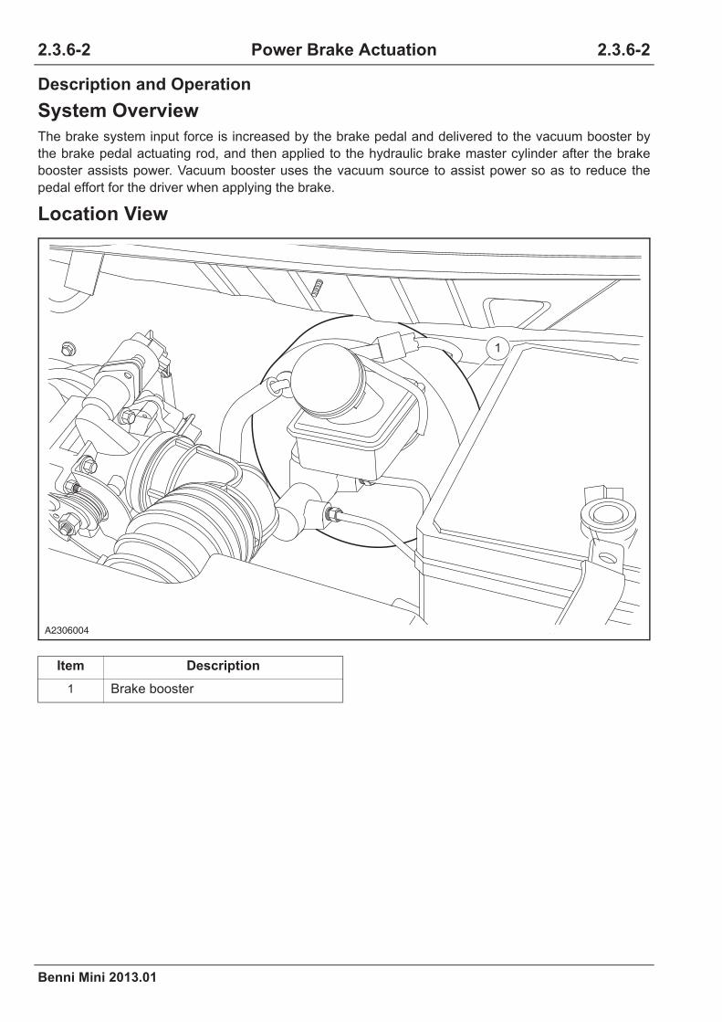
2.3.6-2
Benni Mini 2013.01
2.3.6-2Power Brake Actuation
Description and Operation
System Overview
The brake system input force is increased by the brake pedal and delivered to the vacuum booster by
the brake pedal actuating rod, and then applied to the hydraulic brake master cylinder after the brake
booster assists power. Vacuum booster uses the vacuum source to assist power so as to reduce the
pedal effort for the driver when applying the brake.
Location View
Item Description
1 Brake booster
1
A2306004

Benni Mini 2013.01
2.3.6-3 2.3.6-3Power Brake Actuation
Removal and Installation
Brake Booster
Removal
1. Drain the brake fluid from the reservoir.
1.Connect one end of a suitable piece of clear
plastic pipe to the system bleeding nozzle
and place the other end into a suitable con-
tainer.
2.Loosen the brake bleeding nozzle.
3.Depress the brake pedal until all the brake
fluid is drained from the brake fluid reservoir.
4.Tighten the brake bleeding nozzle.
CAUTION: Repeat the draining procedure
on the opposite side brake.
2. Remove the brake master cylinder.
Refer to: Brake Master Cylinder and Brake
Fluid Reservoir (2.3.5 Hydraulic Brake
Actuation, Removal and Installation).
CAUTION: If the brake fluid is spilled on
the paintwork, the affected area must be
immediately washed down with cold water.
3. Release the vacuum booster tube snap ring
and detach the vacuum booster tube.
2
1
43
A2305002
A2306001

2.3.6-4
Benni Mini 2013.01
2.3.6-4Power Brake Actuation
Installation
4. Remove the brake booster.
1.Remove the brake push rod and the brake
pedal retaining clamp, detach the push rod
retaining pin.
2.Remove the 4 mounting bolts on the brake
booster.
Torque: 25 Nm
5. Remove the brake booster.
1. To install, reverse the removal procedure.
2. Brake system bleeding.
Refer to: Brake System Bleeding (2.3.1
Brake System - General Information, Gen-
eral Procedures).
CAUTION: Make sure that the brake
booster push rod is correctly located
before the installation.
CAUTION: Make sure that the brake mas-
ter cylinder vacuum seal is correctly
located before the installation.
2×4
1
A2306002
A2306003

Benni Mini 2013.01
2.3.7-1 2.3.7-1Anti-Lock Control
Specifications
Material Specifications
Torque Specifications
Item Specification
Brake fluid HZY4
Item Nm lb-ft lb-in
Electronic hydraulic control unit retaining
bolt9 - 80
Brake line and electronic hydraulic control
unit connection retaining bolt16 12 -
Front wheel speed sensor retaining bolt 9 - 80
Rear wheel speed sensor retaining bolt 23 17 -
2.3.7 Anti-lock Control

2.3.7-2
Benni Mini 2013.01
2.3.7-2Anti-Lock Control
Description and Operation
System Overview
MK70-M Anti-lock Brake System (ABS)
The MK70-M type ABS is designed especially for small and medium-sized vehicles. Compared with the
MK20 ABS system, it greatly reduces the size of the electric control and hydraulic control unit (such as
hydraulic valve and solenoid valve), and the housing size. So the weight of the whole ABS hydraulic con-
trol unit greatly reduces. The hydraulic control unit comprises the pump, the valve body (which contains
eight hydraulic valves) and the electronic control unit. The ABS control module controls the ABS warning
lamp ON and OFF in the instrument panel via the K-line. The MK70-M type ABS is a system called "4/4".
That is the wheel speed of the four wheels is measured separately. (Use four wheel speed sensors.) The
ABS uses the independent control for four wheels.
Component Description
1. Hydraulic Electronic Control Unit
CAUTION: There is a rubber damping pad between the mounting bolt and the bracket of the
hydraulic electronic control unit. The rubber damping pad is used to prevent from the hydrau-
lic electronic control unit from the vehicle vibration.
The hydraulic electronic control unit can not be disassembled but replaced as an assembly.
The main components of the hydraulic electronic control unit includes the ABS control module, the valve
body and the ABS pump.
23
1
A2307011

Benni Mini 2013.01
2.3.7-3 2.3.7-3Anti-Lock Control
Function
As the closed-loop control system, the purpose of the ABS brake system is to prevent the failure of the
steering and the driving performance during the wheel brake lock.
ABS control module
The ABS control module compares the deceleration limit value of its own storage with the deceleration
value detected from each vehicle wheel speed sensor, so you can detect the locking tendency of each
wheel. If the ABS control module detects a wheel with the locking tendency, the corresponding hydraulic
valves of the valve body will be opened or closed. The ABS control module also sends the detected
wheel speed sensor signals to the power control module (PCM). The ABS control module opens the
ABS warning lamp located in the instrument panel when switching on the ignition switch. The warning
lamp will remain lit until the ABS completes the system self-test. The system failure warning lamp will
also be opened (as a warning). The ABS control module keeps monitoring any possible system failure, in
the event, it will automatically store. The DTC can be found by connecting the DLC with the WDS. The
ABS is connected with the DLC directly via the diagnosis data interface.
Valve assembly
The valve assembly includes four inlet valves with four oil outlet valves. Each wheel has an oil inlet valve
and an oil outlet valve.
The oil inlet valve is opened and the oil outlet valve is closed when it is out of power.
The valve assembly also includes a low pressure reservoir and a noise reduction chamber.
ABS pump
When the ABS pump works, the ABS pump provides sufficient pressure for the brake master pump to
ensure that the role of the independent adjustment of the respective channels.
ABS hydraulic control adjustment cycle
One ABS adjustment cycle consists of three stages:
First stage - packing stage:
The oil inlet valve is closed, the wheel brake (slave pump) pressure can be no longer changed, that is
the slave pump pressure will not be changed even you depress the brake pedal down again.
Second stage - decompression stage:
The oil outlet valve is temporarily opened, the pressure in the wheel brake (slave pump) is decreased in
a controlled manner.
Third stage - boosting stage:
The intake valve is gradually opened, the brake pressure is increased in a controlled manner to obtain
the best braking effect.
Item Description Item Description
1 Pump 3 ABS control module
2 Valve body

2.3.7-4
Benni Mini 2013.01
2.3.7-4Anti-Lock Control
Anti-lock Brake System (ABS) Hydraulic Line Schematic Diagram
Item Description Item Description
AV Normally closed solenoid valve RR Right rear wheel
EV Normally open solenoid valve LR Left rear wheel
M Motor RF Right front wheel
LF Left front wheel A1 Pressure accumulator 1
A2 Pressure accumulator 2 B1 Buffer 1
B2 Buffer 2
RF LR RR LF
-
-
-
-
RFEV
RFAV
A2
FP2
MC2 MC1
pedal assistance
2 bar admission pressure
M-FP1
-
-LREV
-
-RREV
-
-LFEV
-LRAV
-
-
RRAV
A1
-LFAV
B1B2
A2307012

Benni Mini 2013.01
2.3.7-5 2.3.7-5Anti-Lock Control
2. Wheel Speed Sensor
The wheel speed sensor is a passive two-wire sensor. With the wheel rotation, the ABS control module
uses the wheel speed signal to calculate the wheel speed and acceleration. The sensor obtains the
pulse signal from the ring gear, and the signal is transfered into a digital signal by the circuit integrated in
the sensor and then passed to the ABS control module. The front wheel ring gear is fixed on the halfshaft
as its integral. The rear wheel ring gear is fixed on the rear bearing.
3. Brake Lamp Switch
The brake lamp is on when the brake pedal is depressed, meanwhile, the brake signal is sent to the ABS
control module.
4. ABS Indicator Lamp
The ABS indicator lamp is located on the instrument cluster to inform the driver the ABS system failure
by ON. When the ABS works normally, the ignition switch turns from "OFF" to "ON", the ABS system per-
forms the self-test, the indicator lamp lights for about 2.0 s, and then goes out and always remains off.
When the following events occurs, the instrument cluster will light the ABS indicator lamp:
The ABS control module detects the ABS system failure.
The instrument cluster receives a request of lighting the indicator lamp from the ABS control module.
• The ABS performs a self-test at the beginning of each ignition cycle. The indicator lamp lights for
about 2.0 s.
• The instrument cluster detects a loss of communication with the ABS control module.
A2307013

2.3.7-6
Benni Mini 2013.01
2.3.7-6Anti-Lock Control
5. EBD Indicator Lamp
It is located on the instrument cluster to inform the driver the EBD failure by ON. When the ABS indicator
lamp is on but the EBD indicator lamp is off, the system still has the EBD function. When the ABS indica-
tor lamp and the EBD indicator lamp are both on, both the ABS and the EBD functions are invalid.
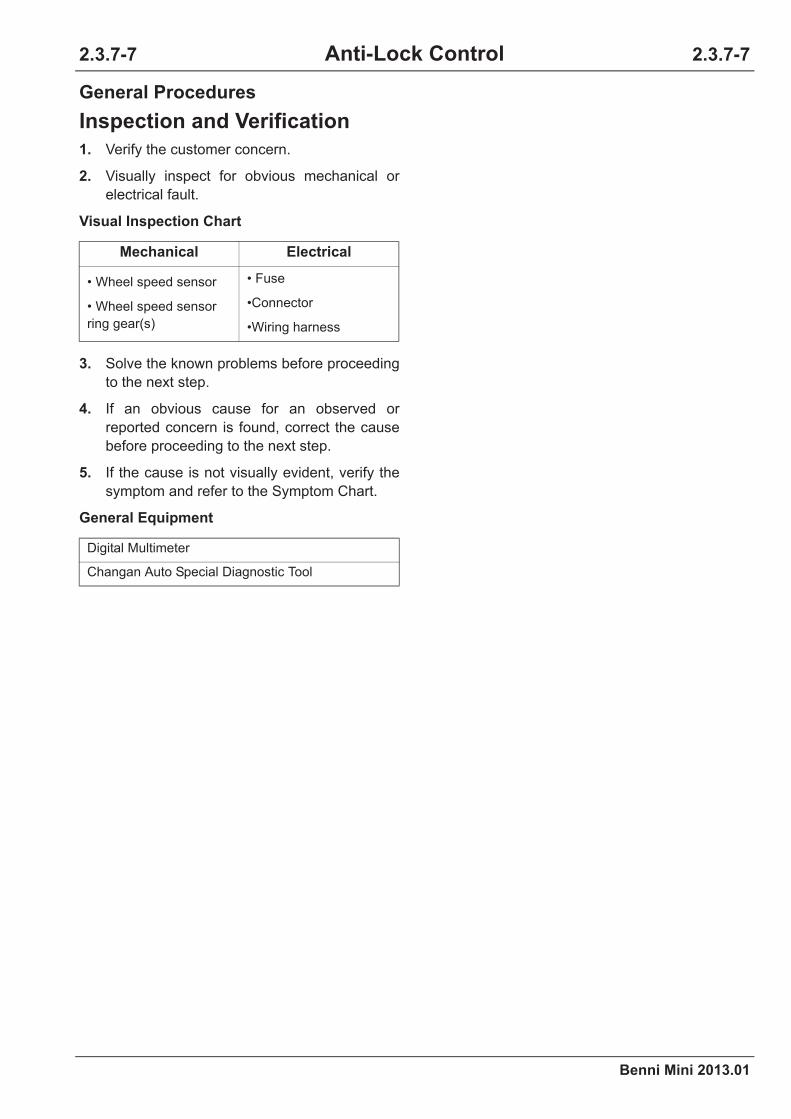
Benni Mini 2013.01
2.3.7-7 2.3.7-7Anti-Lock Control
General Procedures
Inspection and Verification
1. Verify the customer concern.
2. Visually inspect for obvious mechanical or
electrical fault.
Visual Inspection Chart
3. Solve the known problems before proceeding
to the next step.
4. If an obvious cause for an observed or
reported concern is found, correct the cause
before proceeding to the next step.
5. If the cause is not visually evident, verify the
symptom and refer to the Symptom Chart.
General Equipment
Mechanical Electrical
• Wheel speed sensor
• Wheel speed sensor
ring gear(s)
• Fuse
•Connector
•Wiring harness
Digital Multimeter
Changan Auto Special Diagnostic Tool

2.3.7-8
Benni Mini 2013.01
2.3.7-8Anti-Lock Control
Symptom Diagnosis and Testing
Intermittent Malfunction Diagnosis
CAUTION: 1. Clear the DTC.
2. Carry out the simulation test.
3. Inspect and shake the wiring harnesses, connectors and terminals.
When the malfunction can not be inspected by the DTC, it occurs occasionally while being used. Confirm
the circuit and components that may lead to malfunction. In many cases, through the performance of the
the basic inspections shown in the following flowchart, the fault can be quickly and efficiently located,
especially for the poor wiring harness connector contact and other faults. Malfunction definition: This
malfunction currently does not appear, but the historical malfunction diagnosis code record indicates that
the malfunction occurred before. Or the customer reports the malfunction, but as the malfunction is not
related to the malfunction diagnosis code, and currently the malfunction symptoms can not show again.
Test Conditions Details/Results/Actions
1. Vibration method
If driving on a tough roads, the malfunction occurs
or becomes more serious, or the engine starts
vibration, perform the following steps.
CAUTION: Some reasons may cause vehi-
cle or engine electrical failure. Inspect the
following items:
1. The connector is not fully in position.
2. The wiring harness does not have
enough clearance.
3. The wiring harness layout is across the
bracket or moving components.
4. The wiring harness lays too close to the
high temperature components.
CAUTION: Incorrect wiring, tight or loose
wiring harness will lead the connecting
cable to be squeezed between the compo-
nents.
CAUTION: The connector joint, the vibra-
tion location, the location of the wiring
harness crossing are all required for
focus inspection, such as: wiring harness
across the firewall and the body panels.

Benni Mini 2013.01
2.3.7-9 2.3.7-9Anti-Lock Control
2. Inspection method of the switch connector or wiring harness
1.Connect the diagnostic tool to the data link
connector (DLC).
2.Turn the ignition switch to position "ON" (stop the
engine).
3.Access to the switch data stream that you are
inspecting.
4.Turn on the switch manually.
5.When monitoring the data stream, vertically,
horizontally gently shake each connector or wiring
harness.
If the data stream value is unstable, please inspect
if there is a bad connection.
3. Sensor connector or wiring harness inspection method
1.Connect the diagnostic tool to the data link
connector (DLC).
2.Turn the ignition switch to position "ON" (stop the
engine).
3.Access to the switch data stream that you are
inspecting.
4.When monitoring the data stream, vertically,
horizontally gently shake each connector or wiring
harness.
If the data stream value is unstable, please inspect
if there is a bad connection.
4. Inspect method of the actuator or relay
1.Connect the diagnostic tool to the data link
connector (DLC).
2.Turn the ignition switch to position "ON" (stop the
engine).
3.Perform the active test on the inspected actuator or
relay.
Refer to: Active Test List (2.3.7 Anti-lock
Control, DTC Control and Testing).
Test Conditions Details/Results/Actions
A2307014
A2307015

2.3.7-10
Benni Mini 2013.01
2.3.7-10Anti-Lock Control
ABS Warning Lamp Is OFF Diagnosis
ABS warning lamp is off diagnosis
Refer to: Symptom Chart (4.3.2 Instrument Cluster, Symptom Diagnosis and Testing).
5. Perform the road test to simulate the failure and read the data stream.
1.Connect the diagnostic tool to to data link connector
(DLC).
2.Perform the road test to simulate the failure and
read the data stream.
Refer to: Data Stream List (2.3.7 Anti-lock
Control, DTC Control and Testing).
CAUTION: This work needs two people's
cooperation.
If the data stream value is unstable or fails, please
repair or replace the components.
Test Conditions Details/Results/Actions

Benni Mini 2013.01
2.3.7-11 2.3.7-11Anti-Lock Control
ABS Warning Lamp Always ON Diagnosis
Test Conditions Details/Results/Actions
1. Read the ABS anti-lock control system fault codes
A.Connect the special diagnostic tool.
B.Turn the ignition switch to position "ON" and read
the DTC of the ABS anti-lock control system on the
special diagnostic tool.
Are there any ABS anti-lock control system fault
codes?
Y
Repair according to the instruction of the DTC.
Refer to: DTC Diagnosis Chart (2.3.7 Anti-
lock Control, DTC Diagnosis and Testing).
N
Go to step 2.
2. Inspect the wiring harness between the instrument and the ABS control module.
A.Turn the ignition switch to position "LOCK" and
disconnect the battery negative cable.
B.Disconnect the instrument cluster wiring harness
connector P07.
C.Disconnect the ABS control module wiring harness
connector C12.
D.Measure the resistance between the terminal 18 of
the instrument cluster wiring harness connector
P07 and the terminal 10 of the ABS control module
wiring harness connector C12.
Standard Resistance Value: less than 5
E.Measure the voltage between the terminal 18 of the
instrument cluster wiring harness connector P07
and the terminal 10 of the ABS control module
wiring harness connector C12 respectively.
Standard Voltage Value: 0 V
Is the resistance value normal?
Y
Go to step 3.
N
Inspect and repair the circuit fault of the circuit
between the terminal 18 of the instrument cluster
wiring harness connector P07 and the terminal 10
of the ABS control module wiring harness connec-
tor C12.
P07
C12
32
16
17 18
1
13
26
12
15
12 10
25 14
A2307016
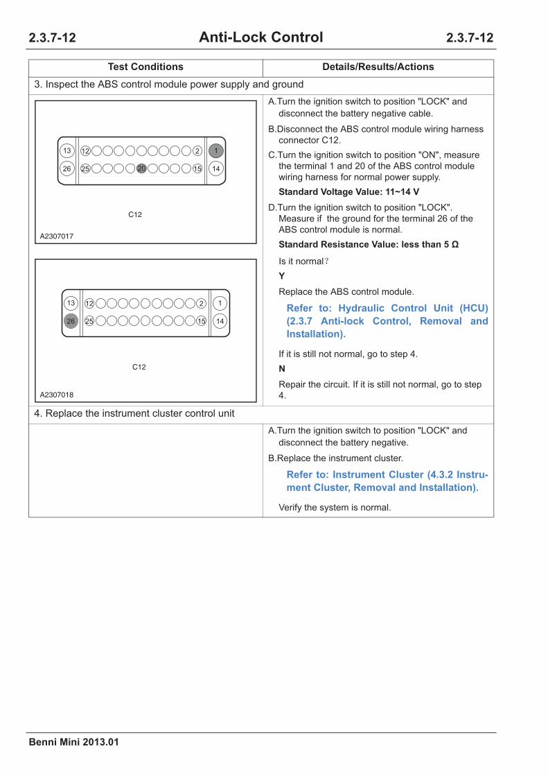
2.3.7-12
Benni Mini 2013.01
2.3.7-12Anti-Lock Control
3. Inspect the ABS control module power supply and ground
A.Turn the ignition switch to position "LOCK" and
disconnect the battery negative cable.
B.Disconnect the ABS control module wiring harness
connector C12.
C.Turn the ignition switch to position "ON", measure
the terminal 1 and 20 of the ABS control module
wiring harness for normal power supply.
Standard Voltage Value: 11~14 V
D.Turn the ignition switch to position "LOCK".
Measure if the ground for the terminal 26 of the
ABS control module is normal.
Standard Resistance Value: less than 5
Is it normal
Y
Replace the ABS control module.
Refer to: Hydraulic Control Unit (HCU)
(2.3.7 Anti-lock Control, Removal and
Installation).
If it is still not normal, go to step 4.
N
Repair the circuit. If it is still not normal, go to step
4.
4. Replace the instrument cluster control unit
A.Turn the ignition switch to position "LOCK" and
disconnect the battery negative.
B.Replace the instrument cluster.
Refer to: Instrument Cluster (4.3.2 Instru-
ment Cluster, Removal and Installation).
Verify the system is normal.
Test Conditions Details/Results/Actions
C12
13
26
12
15
12
2025 14
A2307017
C12
13
26
12
15
12
25 14
A2307018
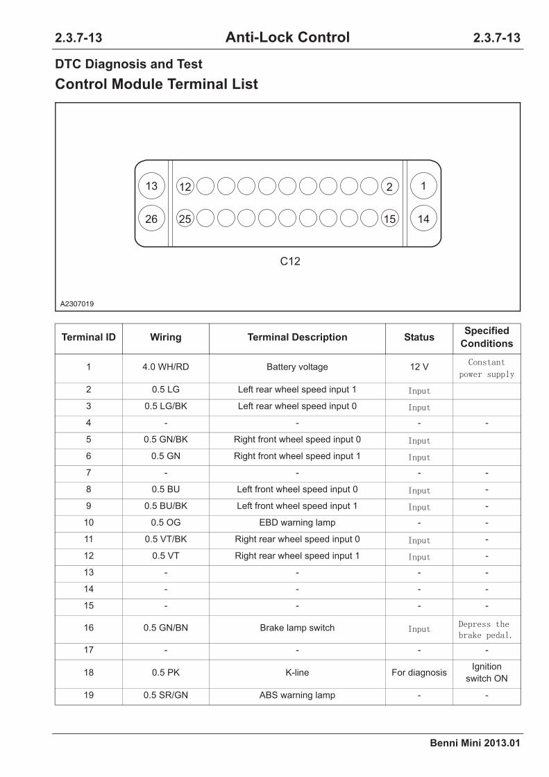
Benni Mini 2013.01
2.3.7-13 2.3.7-13Anti-Lock Control
DTC Diagnosis and Test
Control Module Terminal List
Terminal ID Wiring Terminal Description StatusSpecified
Conditions
1 4.0 WH/RD Battery voltage 12 V
2 0.5 LG Left rear wheel speed input 1
3 0.5 LG/BK Left rear wheel speed input 0
4 - - - -
5 0.5 GN/BK Right front wheel speed input 0
6 0.5 GN Right front wheel speed input 1
7 - - - -
8 0.5 BU Left front wheel speed input 0 -
9 0.5 BU/BK Left front wheel speed input 1 -
10 0.5 OG EBD warning lamp - -
11 0.5 VT/BK Right rear wheel speed input 0 -
12 0.5 VT Right rear wheel speed input 1 -
13 - - - -
14 - - - -
15 - - - -
16 0.5 GN/BN Brake lamp switch
17 - - - -
18 0.5 PK K-line For diagnosisIgnition
switch ON
19 0.5 SR/GN ABS warning lamp - -
13
26
12
15
12
25 14
C12
A2307019

2.3.7-14
Benni Mini 2013.01
2.3.7-14Anti-Lock Control
DTC Code List
20 0.5 WH/GN Ignition switch wire 12VIgnition
switch ON
21 0.5 BU/BK CAN_L CAN bus -
22 - - - -
23 0.5 BU/WH CAN_H CAN bus -
24 - - - -
25 - - - -
26 3.0 BK Ground wire 0V -
Malfunction Description
0x0003 •Controller fault
0x3FD8 •Controller, RAM fault
0x3FD9 •Controller, external RAM fault
0x3FDB •Controller, EEPROM fault
0x3FDC •Controller, calibration and fault
0x3FDE •Controller, self-test fault
0x3FDF •Controller, program fault
0x3FE0 •Controller, electrical fault
0x3FE1 •Controller, function fault
0x3FE3 •Controller, watchdog timer
0x3FF4 •Controller, internal sensor fault
0x0412 •Controller uncoded
0x0414 •No controller code (byte code)
0x029C •Battery voltage KL30 fault
0x046A •ABS works abnormally.
0x0520 •Data bus works abnormally.
0x011B •Left front wheel speed sensor fault
0x011D •Right front wheel speed sensor fault
0x0122 •Left rear wheel speed sensor fault
0x011F •Right rear wheel speed sensor fault
0x020E •Brake lamp switch fault
0x04FC •Hydraulic pump
0x08A6 •Tire pressure warning (reserved)
Terminal ID Wiring Terminal Description StatusSpecified
Conditions

Benni Mini 2013.01
2.3.7-15 2.3.7-15Anti-Lock Control
Data Stream List
By reading the "Data Stream List" on the fault diagnostic tool, do not remove any component, and
inspect the working state of the switches, the sensors, and the actuators. Before the fault diagnosis of
the engine electrical control system, the observation and analysis of the data is the first step in trouble-
shooting, this can reduce the troubleshooting time.
CAUTION: The following table lists the data under normal conditions, only for reference. Do
not determine the failure based on these standard values. Generally, use a normal vehicle to
compare a vehicle in diagnosis under the same state to determine the data of the diagnosis
vehicle under the current state normal or not.
1. Let the engine reach the normal operating temperature.
2. Turn the ignition switch to position "OFF".
3. Connect the fault diagnostic tool.
4. Turn the ignition switch to position "ON".
5. Select "Benni Mini/Continental ABS/Actual values".
6. Refer to the chart below to inspect all the data.
Diagnostic Tool Display Item Data
Left front wheel speed 0 km/h
Right front wheel speed 0 km/h
Left rear wheel speed 0 km/h
Right rear wheel speed 0 km/h
Brake lamp switch status Loose
Brake warning lamp status Disconnect
ABS warning lamp status Disconnect
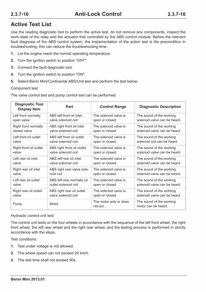
2.3.7-16
Benni Mini 2013.01
2.3.7-16Anti-Lock Control
Active Test List
Use the reading diagnostic tool to perform the active test, do not remove any components, inspect the
work state of the relay and the actuator that controlled by the ABS control module. Before the relevant
fault diagnosis of the ABS control system, the implementation of the action test is the precondition in
troubleshooting, this can reduce the troubleshooting time.
1. Let the engine reach the normal operating temperature.
2. Turn the ignition switch to position "OFF".
3. Connect the fault diagnostic tool.
4. Turn the ignition switch to position "ON".
5. Select Benni Mini/Continental ABS/Unit test and perform the test below:
Component test:
The valve control test and pump control test can be performed.
Hydraulic control unit test:
The control unit tests on the four wheels in accordance with the sequence of the left front wheel, the right
front wheel, the left rear wheel and the right rear wheel, and the testing process is performed in strictly
accordance with the steps.
Test conditions:
1. Test under voltage is not allowed.
2. The wheel speed can not exceed 20 km/h.
3. The test time shall not exceed 90s.
Diagnostic Tool
Display ItemPart Control Range Diagnostic Description
Left front normally
open valve
ABS left front oil inlet
valve solenoid coil
The solenoid valve is
open or closed.
The sound of the working
solenoid valve can be heard.
Right front normally
closed valve
ABS right front oil inlet
valve solenoid coil
The solenoid valve is
open or closed.
The sound of the working
solenoid valve can be heard.
Left front oil outlet
valve
ABS left front oil outlet
valve solenoid coil
The solenoid valve is
open or closed.
The sound of the working
solenoid coil can be heard.
Right front oil outlet
valve
ABS right front oil outlet
valve solenoid coil
The solenoid valve is
open or closed.
The sound of the working
solenoid valve can be heard.
Left rear oil inlet
valve
ABS left rear oil inlet
valve solenoid coil
The solenoid valve is
open or closed.
The sound of the working
solenoid valve can be heard.
Right rear oil inlet
valve
ABS right rear valve sole-
noid coil
The solenoid valve is
open or closed.
The sound of the working
solenoid valve can be heard.
Left rear oil outlet
valve
ABS left rear normally oil
outlet solenoid coil
The solenoid valve is
open or closed.
The sound of the working
solenoid valve can be heard.
Right rear oil outlet
valve
ABS right rear oil outlet
valve solenoid coil
The solenoid valve is
open or closed.
The sound of the working
solenoid valve can be heard.
Pump MotorThe motor acts or does
not act.
The sound of the working
motor can be heard.

Benni Mini 2013.01
2.3.7-17 2.3.7-17Anti-Lock Control
Procedures:
Confirm each sub-step in order.
1. Depress and hold the brake pedal.
2. The normally open valve is opened, the normally closed valve is closed, and the wheels are locked.
3. The normally open valve is closed, the normally closed valve is closed, and the wheels are locked.
4. The normally open valve is closed, the normally closed valve is opened, and the wheels are locked.
5. The normally open valve is closed, the normally closed valve is closed, and the wheels are locked.
6. The normally open valve is opened, the normally closed valve is closed, and the wheels are locked.
7. Release the brake pedal.
Bleeding and filling test:
First bleed the conventional brake system.
Refer to: (2.3.1 Brake System - General Information, General Procedures).
Then perform strictly in accordance with the following steps.
1. Depresses the brake pedal, and keep the hydraulic pump working.
2. Release the brake pedal, deflate the left and right front brake caliper.
3. Depress the brake pedal for 10 times.
4. Exist.
Diagnostic Tool Can Not Communicate With the Vehicle Diagnosis
CAUTION: The internal module short circuit can also cause the fault.
Refer to: Diagnostic Tool Can Not Communicate With ECM Diagnosis (4.3.15 On-board Net-
work, Symptom Diagnosis and Testing).

2.3.7-18
Benni Mini 2013.01
2.3.7-18Anti-Lock Control
DTC Diagnosis Chart
Malfunction Description Diagnosis Procedures
0x0003 •Controller fault Refer to: Power Supply Fault and Hydraulic
Electrical Control Unit Assembly Internal Fault
Diagnosis (2.3.7 Anti-lock Control, DTC Diag-
nosis and Testing).
0x3FD8 •Controller, RAM fault
0x3FD9•Controller, external RAM
fault
0x3FDB•Controller, EEPROM
fault
0x3FDC•Controller, calibration
and fault
0x3FDE •Controller, self-test fault
0x3FDF •Controller, program fault
0x3FE0•Controller, electrical
fault
0x3FE1 •Controller, function fault
0x3FE3•Controller, watchdog
timer
0x3FF4•Controller, internal sen-
sor fault
0x0412 •Controller uncoded
0x0414•Wrong controller code
(byte code)
0x029C•Battery voltage KL30
fault
0x046A •ABS working abnormally
0x04FC •Hydraulic pump
0x011B•Left front wheel speed
sensor fault
Refer to: Wheel Speed Sensor Diagnosis (2.3.7
Anti-lock Control, DTC Diagnosis and Testing).
0x011D•Right front wheel speed
sensor fault
0x0122•Left rear wheel speed
sensor fault
0x011F•Right rear wheel speed
sensor fault
0x0520•Data bus works abnor-
mally
Refer to: Abnormal Data Bus Diagnosis (2.3.7
Anti-lock Control, DTC Diagnosis and Testing).
0x020E •Brake light switch fault
Refer to: Brake Lamp Switch Fault Diagnosis
(2.3.7 Anti-lock Control, DTC Diagnosis and
Testing).

Benni Mini 2013.01
2.3.7-19 2.3.7-19Anti-Lock Control
Power Supply Fault and Hydraulic Electrical Control Unit Assem-
bly Internal Fault Diagnosis
Test Conditions Details/Results/Actions
1. Inspect the battery voltage
A.Turn the ignition switch to position "ST" and start the
engine.
B.Use the multimeter to measure the battery voltage
for normal value.
Standard Voltage Value: 11~16 V
Is the voltage normal
Y
Go to step 2.
N
Refer to: Battery Undercharge Diagnosis,
Battery Overcharge Diagnosis (Charging
System, Symptom Diagnosis and Test-
ing).
2. ABS control module power supply and ground
A.Turn the ignition switch to position "LOCK" and
disconnect the battery negative cable.
B.Disconnect the ABS control module wiring harness
connector C12.
C.Turn the ignition switch to position "ON", measure
the terminal 1 and 20 of the ABS control module
wiring harness connector C12 for normal power
supply.
Standard Voltage Value: 11~14 V
D.Turn the ignition switch to position "LOCK",
measure the terminal 26 of the ABS control module
wiring harness connector C12 for normal ground.
Standard Resistance Value: less than 5
Is it normal
Y
Go to step 3.
N
Repair the circuit.
C12
13
26
12
15
12
2025 14
A2307017
C12
13
26
12
15
12
25 14
A2307018

2.3.7-20
Benni Mini 2013.01
2.3.7-20Anti-Lock Control
Wheel Speed Sensor Diagnosis
CAUTION: The maintenance manual is only for the left front wheel speed sensor fault diagno-
sis, similar to the diagnostic way of the rest wheel speed sensors.
Refer to: (Left front wheel speed sensor fault diagnosis)
3. Use the special diagnostic tool to access the ABS control module
A.Use the special diagnostic tool to access the ABS
control module to perform the active test on the
ABS pump.
Can the sound of the working ABS pump be heard?
Y
System is normal.
N
Replace the ABS control module.
Refer to: Hydraulic Control Unit (HCU)
(2.3.7 Anti-lock Control, Removal and
Installation).
Test Conditions Details/Results/Actions
1. Inspect the installation of the left front wheel speed sensor
A.Inspect the installation of the left front wheel speed
sensor.
Is it loose?
Y
Tighten it.
N
Go to step 2.
2. Inspect the left front wheel speed sensor wheel speed data
A.Use the diagnostic tool to observe the wheel speed
sensor speed data.
Are the data the same as other wheels?
Y
Go to step 3.
N
Replace the left front wheel speed sensor.
Test Conditions Details/Results/Actions
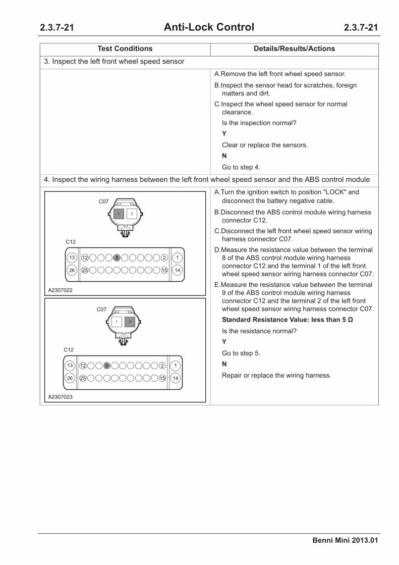
Benni Mini 2013.01
2.3.7-21 2.3.7-21Anti-Lock Control
3. Inspect the left front wheel speed sensor
A.Remove the left front wheel speed sensor.
B.Inspect the sensor head for scratches, foreign
matters and dirt.
C.Inspect the wheel speed sensor for normal
clearance.
Is the inspection normal?
Y
Clear or replace the sensors.
N
Go to step 4.
4. Inspect the wiring harness between the left front wheel speed sensor and the ABS control module
A.Turn the ignition switch to position "LOCK" and
disconnect the battery negative cable.
B.Disconnect the ABS control module wiring harness
connector C12.
C.Disconnect the left front wheel speed sensor wiring
harness connector C07.
D.Measure the resistance value between the terminal
8 of the ABS control module wiring harness
connector C12 and the terminal 1 of the left front
wheel speed sensor wiring harness connector C07.
E.Measure the resistance value between the terminal
9 of the ABS control module wiring harness
connector C12 and the terminal 2 of the left front
wheel speed sensor wiring harness connector C07.
Standard Resistance Value: less than 5
Is the resistance normal?
Y
Go to step 5.
N
Repair or replace the wiring harness.
Test Conditions Details/Results/Actions
C12
C07
1 2
13
26
12
15
12 8
25 14
A2307022
C12
C07
1 2
13
26
12
15
12 9
25 14
A2307023
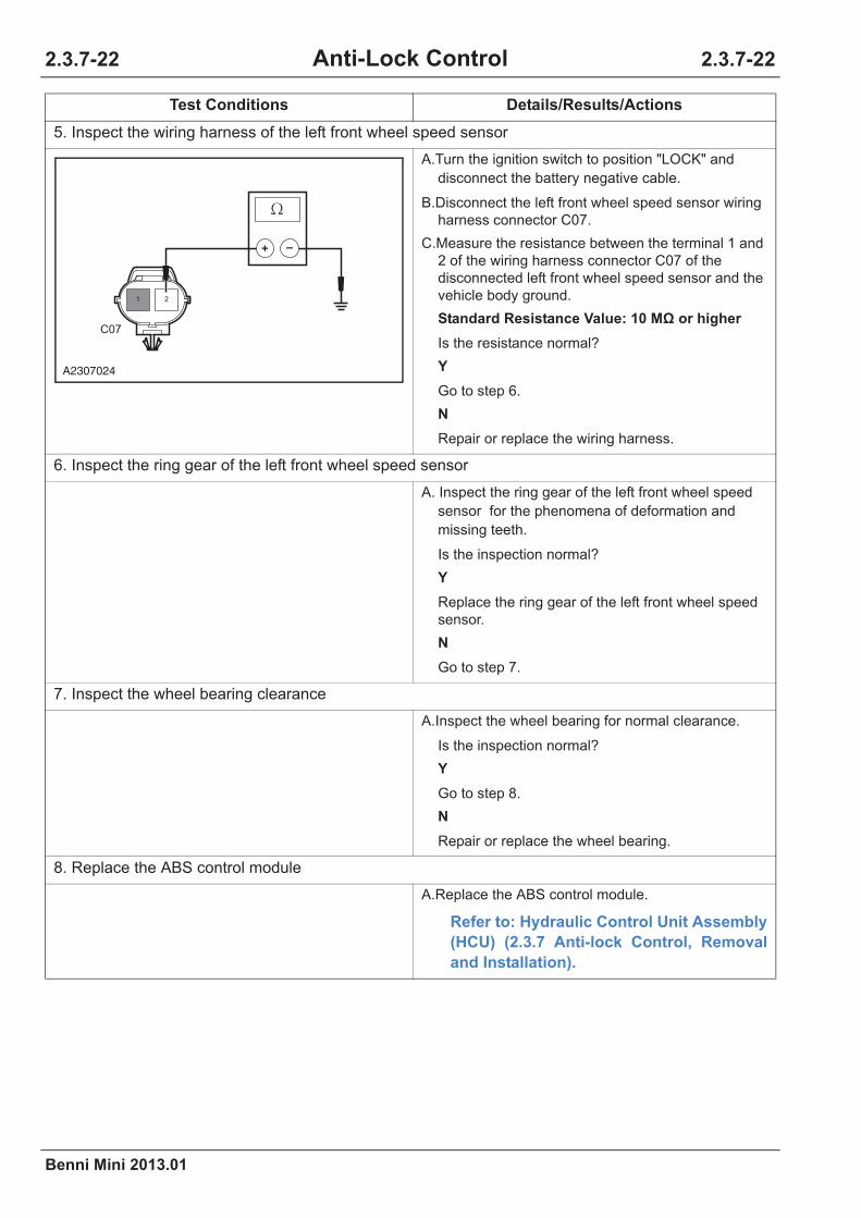
2.3.7-22
Benni Mini 2013.01
2.3.7-22Anti-Lock Control
5. Inspect the wiring harness of the left front wheel speed sensor
A.Turn the ignition switch to position "LOCK" and
disconnect the battery negative cable.
B.Disconnect the left front wheel speed sensor wiring
harness connector C07.
C.Measure the resistance between the terminal 1 and
2 of the wiring harness connector C07 of the
disconnected left front wheel speed sensor and the
vehicle body ground.
Standard Resistance Value: 10 M or higher
Is the resistance normal?
Y
Go to step 6.
N
Repair or replace the wiring harness.
6. Inspect the ring gear of the left front wheel speed sensor
A. Inspect the ring gear of the left front wheel speed
sensor for the phenomena of deformation and
missing teeth.
Is the inspection normal?
Y
Replace the ring gear of the left front wheel speed
sensor.
N
Go to step 7.
7. Inspect the wheel bearing clearance
A.Inspect the wheel bearing for normal clearance.
Is the inspection normal?
Y
Go to step 8.
N
Repair or replace the wheel bearing.
8. Replace the ABS control module
A.Replace the ABS control module.
Refer to: Hydraulic Control Unit Assembly
(HCU) (2.3.7 Anti-lock Control, Removal
and Installation).
Test Conditions Details/Results/Actions
1 2
C07
A2307024

Benni Mini 2013.01
2.3.7-23 2.3.7-23Anti-Lock Control
Abnormal Data Bus Diagnosis
Test Conditions Details/Results/Actions
1. Inspect the DTC
A.Connect the diagnostic tool.
B.Use the diagnostic tool to diagnose the ABS
system.
Are there any DTC except for 0x0520?
Y
Refer to: DTC Diagnosis Chart (3.1.13
Electronic control System - ME7, DTC
Diagnosis and Testing).
N
Go to step 3.
2. General inspection
A.Inspect the related wiring harness connectors for
signs of damage, poor contact, aging or loose.
Is it normal?
Y
Go to step 3.
N
Repair the fault.
3. Inspect the CAN bus for integrity
A.Inspect the CAN bus for integrity.
Refer to: CAN bus Integrity Inspection
(4.3.15 On-board Network System, Symp-
tom Diagnosis and Testing).
Is the result normal?
Y
Go to step 4.
N
Inspect and repair the circuit for open circuit.

2.3.7-24
Benni Mini 2013.01
2.3.7-24Anti-Lock Control
4. ABS control module power supply and ground
A.Turn the ignition switch to position "LOCK" and
disconnect the battery negative cable.
B.Disconnect the ABS control module wiring harness
connector C12.
C.Turn the ignition switch to position "ON", measure
the terminal 1 and 20 of the ABS control module
wiring harness connector C12 for normal power
supply.
Standard Voltage Value: 11~14 V
D.Turn the ignition switch to position "LOCK",
measure the terminal 26 of the ABS control module
wiring harness connector C12 for normal
grounding.
Standard Resistance Value: less than 5
Is it normal
Y
Go to step 5.
N
Repair the circuit.
5. Use the special diagnostic tool to access the ABS control module
A.Use the special diagnostic tool to access the ABS
control module to perform the active test on the
ABS pump.
Can the sound of the working ABS pump be heard?
Y
System is normal.
N
Replace the ABS control module.
Refer to: Hydraulic Control Unit (HCU)
(2.3.7 Anti-lock Control, Removal and
Installation).
Test Conditions Details/Results/Actions
C12
13
26
12
15
12
2025 14
A2307017
C12
13
26
12
15
12
25 14
A2307018

Benni Mini 2013.01
2.3.7-25 2.3.7-25Anti-Lock Control
Brake Lamp Switch Fault
Test Conditions Details/Results/Actions
1. General inspection
A.Inspect the brake lamp switch wiring harness
connector and the brake lamp wiring harness
connector for signs of damage, poor contact, aging
and loose.
B.Inspect the filament and the lamp holder of the
brake lamp bulb for abnormal conditions such as
breakage and oxidation.
Is it normal?
Y
Go to step 2.
N
Repair the fault.
2. Inspect the fuse
A.Inspect the brake lamp fuse IF01.
Fuse Rated Capacity: 10 A
Is the fuse normal?
Y
Go to step 3.
N
Inspect and repair the fuse circuit, replace the fuse
in rated capacity.
3. Inspect the brake lamp switch
A.Depresses the brake pedal to see if the brake lamp
works.
Is it normal?
Y
Go to step 4.
N
Inspect and repair the brake lamp circuit for open
circuit.
Refer to: Brake Lamp Fault Diagnosis
(4.3.7 Lighting System, Symptom Diagno-
sis and Testing).

2.3.7-26
Benni Mini 2013.01
2.3.7-26Anti-Lock Control
4. Inspect the circuit between the brake lamp switch and the ABS
A.Turn the ignition switch to position "LOCK" and
disconnect the battery negative cable.
B.Disconnect the brake lamp switch wiring harness
connector P17a.
C.Disconnect the ABS control module wiring harness
connector C12.
D.Measure the resistance between the terminal 2 of
the brake lamp switch wiring harness connector
P17a and the terminal 16 of the ABS control
module wiring harness connector C12.
Standard Resistance Value: less than 5
Is it normal?
Y
Go to step 5.
N
Inspect and repair the open circuit of the circuit
between the terminal 2 of the brake lamp switch
wiring harness connector P17a and the terminal 16
of the ABS control module wiring harness connec-
tor C12.
Test Conditions Details/Results/Actions
P17a
1
3 4
2
C12
13
26
12
16 15
12
25 14
A2307025

Benni Mini 2013.01
2.3.7-27 2.3.7-27Anti-Lock Control
5. The ABS control module power supply and ground
A.Turn the ignition switch to position "LOCK" and
disconnect the battery negative cable.
B.Disconnect the ABS control module wiring harness
connector C12.
C.Turn the ignition switch to position "ON", measure
the terminal 1 and 20 of the ABS control module
wiring harness C12 for normal power supply.
Standard Voltage Value: 11~14 V
D.Turn the ignition switch to position "LOCK",
measure the terminal 26 of the ABS control module
wiring harness connector C12 for normal ground.
Standard Resistance Value: less than 5
Is it normal
Y
Go to step 6.
N
Repair the circuit.
6. Use the special diagnostic tool to access the ABS control module
A.Use the special diagnostic tool to access the ABS
control module to perform the active test on the
ABS pump.
Can the sound of the working ABS pump be heard?
Y
System is normal.
N
Replace the ABS control module.
Refer to: Hydraulic Control Unit (HCU)
(2.3.7 Anti-lock Control, Removal and
Installation).
Test Conditions Details/Results/Actions
C12
13
26
12
15
12
2025 14
A2307017
C12
13
26
12
15
12
25 14
A2307018
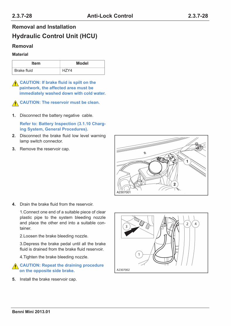
2.3.7-28
Benni Mini 2013.01
2.3.7-28Anti-Lock Control
Removal and Installation
Hydraulic Control Unit (HCU)
Removal
Material
Item Model
Brake fluid HZY4
CAUTION: If brake fluid is spilt on the
paintwork, the affected area must be
immediately washed down with cold water.
CAUTION: The reservoir must be clean.
1. Disconnect the battery negative cable.
Refer to: Battery Inspection (3.1.10 Charg-
ing System, General Procedures).
2. Disconnect the brake fluid low level warning
lamp switch connector.
3. Remove the reservoir cap.
4. Drain the brake fluid from the reservoir.
1.Connect one end of a suitable piece of clear
plastic pipe to the system bleeding nozzle
and place the other end into a suitable con-
tainer.
2.Loosen the brake bleeding nozzle.
3.Depress the brake pedal until all the brake
fluid is drained from the brake fluid reservoir.
4.Tighten the brake bleeding nozzle.
CAUTION: Repeat the draining procedure
on the opposite side brake.
5. Install the brake reservoir cap.
1
2
A2307001
A2307002
2 4
1
3

Benni Mini 2013.01
2.3.7-29 2.3.7-29Anti-Lock Control
6. Disconnect the ABS control module wiring
harness connector.
7. Remove the six brake pipes from the
hydraulic control module.
CAUTION: Block the hydraulic control unit
(HCU) to prevent the brake fluid flowing or
any dirt entering into the brake pipes.
CAUTION: Cover the brake pipes to pre-
vent the brake fluid flowing or any dirt
entering into the brake pipes.
CAUTION: Note the position of the brake
pipes to aid installation.
8. Remove retaining bolts on the hydraulic
control module.
Torque: 8 Nm
A2307003
×6
A2307004
×2
A2307005

2.3.7-30
Benni Mini 2013.01
2.3.7-30Anti-Lock Control
Installation
Rear Wheel Speed Sensor
Removal
1. To install, reverse the removal procedure.
2. Brake system bleeding.
Refer to: Brake System Bleeding (2.3.1
Brake System-General Information, Gen-
eral Procedures).
CAUTION: Make sure that the brake
booster push rod is correctly located
before the installation.
CAUTION: Make sure that the brake mas-
ter pump vacuum seal is correctly located
before the installation.
1. Disconnect the battery negative cable.
Refer to: Battery Inspection (3.1.10 Charg-
ing System, General Procedures).
2. Lift the vehicle.
Refer to: Lifting (1.1.3 Traction and Lifting,
Description and Operation).
3. Remove the rear wheel speed sensor from
both brake bottom plates.
1.Remove the rear wheel speed sensor
retaining bolts on the brake bottom plates.
Torque: 23.5 Nm
A2307006

Benni Mini 2013.01
2.3.7-31 2.3.7-31Anti-Lock Control
Installation
1. To install, reverse the removal procedure.
4. Disconnect the wheel speed sensor wiring
harness connector.
5. Detach the wiring harness buckle from the
suspension arm and the vehicle body.
6. Detach the rear wheel speed sensor.
×3
A2307007
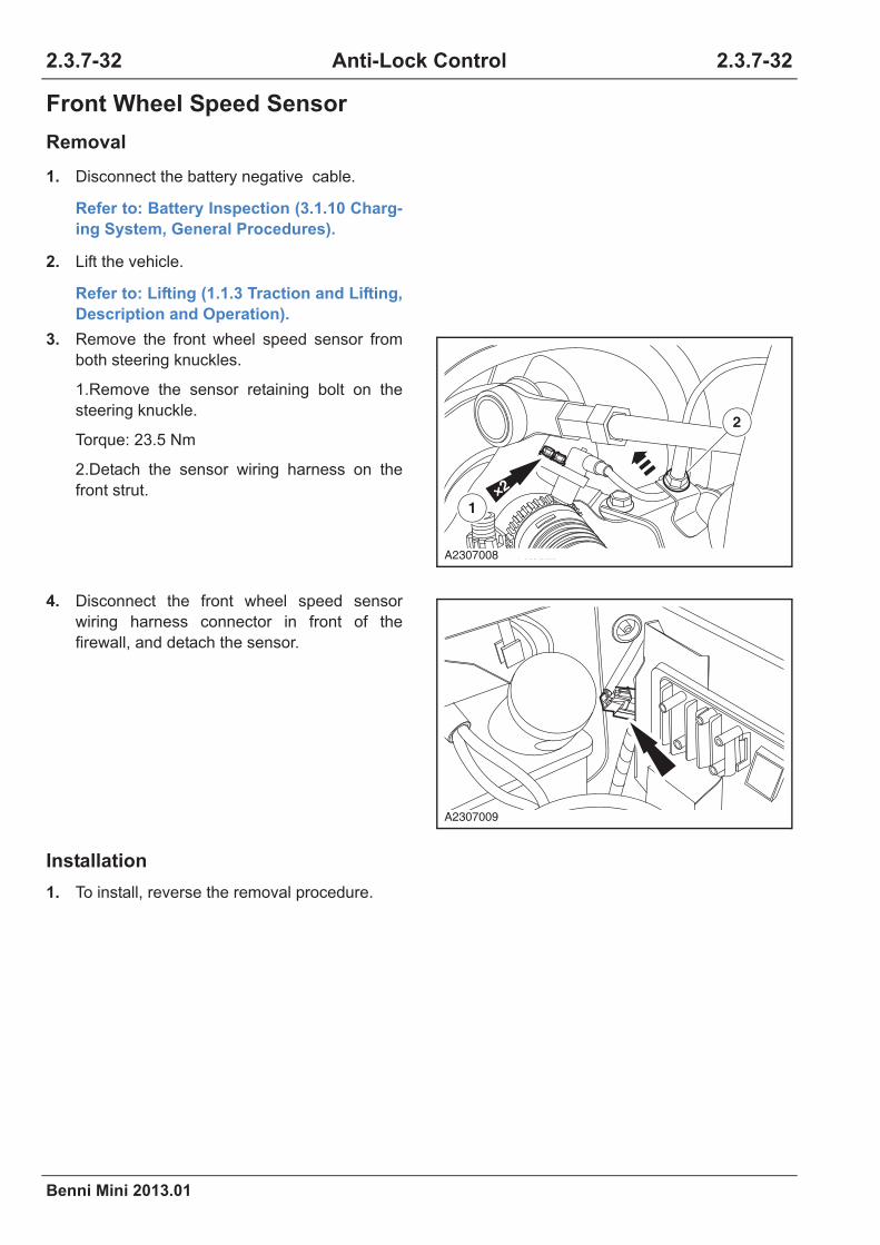
2.3.7-32
Benni Mini 2013.01
2.3.7-32Anti-Lock Control
Front Wheel Speed Sensor
Removal
Installation
1. To install, reverse the removal procedure.
1. Disconnect the battery negative cable.
Refer to: Battery Inspection (3.1.10 Charg-
ing System, General Procedures).
2. Lift the vehicle.
Refer to: Lifting (1.1.3 Traction and Lifting,
Description and Operation).
3. Remove the front wheel speed sensor from
both steering knuckles.
1.Remove the sensor retaining bolt on the
steering knuckle.
Torque: 23.5 Nm
2.Detach the sensor wiring harness on the
front strut.
4. Disconnect the front wheel speed sensor
wiring harness connector in front of the
firewall, and detach the sensor.
2
×2
1
A2307008
A2307009

Benni Mini 2013.01
2.3.7-33 2.3.7-33Anti-Lock Control
Rear Wheel Speed Sensor Ring(s)
Removal
Installation
1. Remove the rear wheel bearing.
Refer to: Rear Wheel Bearing (2.1.3 Rear
Suspension, Removal and Installation).
2. Remove and discard the rear wheel speed
sensor ring(s).
1. Use a suitable hydrostatic machine to install
the new wheel speed sensor ring(s).
CAUTION: Make sure the rings is not
knocked, damaged and stuck with metal
scraps during the operation.
CAUTION: Place a non-ferrous protection
slab to avoid any damage.
CAUTION: Make sure the brake drum is
sufficiently supported and not seized at
the wheel bolts.
CAUTION: During the installation, apply a
slow and even force until the brake drum
is completely settled.
2. Install the rear wheel bearing.
Refer to: Rear Wheel Bearing (2.1.3 Rear
Suspension, Removal and Installation).
A2307010


Benni Mini 2013.01
Steering System
2.4 Steering System
2012 Benni Mini
2.4.1 Steering System - General Information
Specifications ................................................................................................................................... 2.4.1-1
General Specifications.............................................................................................................. 2.4.1-1
Description and Operation ............................................................................................................... 2.4.1-2
System Overview...................................................................................................................... 2.4.1-2
Component Description ............................................................................................................ 2.4.1-3
Exploded View.......................................................................................................................... 2.4.1-6
General Procedures......................................................................................................................... 2.4.1-7
Steering Linkage Inspection ..................................................................................................... 2.4.1-7
Steering Wheel Free Clearance Inspection .............................................................................. 2.4.1-7
Symptom Diagnosis and Testing...................................................................................................... 2.4.1-8
Inspection and Verification........................................................................................................ 2.4.1-8
Symptom Chart......................................................................................................................... 2.4.1-9
Steering Wheel Shaking While Braking Diagnosis ................................................................. 2.4.1-12
2.4.2 Power Steering System
Specifications ................................................................................................................................... 2.4.2-1
General Specifications.............................................................................................................. 2.4.2-1
Torque Specifications................................................................................................................ 2.4.2-1
Description and Operation ............................................................................................................... 2.4.2-2
System Overview...................................................................................................................... 2.4.2-2
Component Description ............................................................................................................ 2.4.2-2
General Procedures......................................................................................................................... 2.4.2-4
Steering Force Inspection......................................................................................................... 2.4.2-4
Symptom Diagnosis and Testing...................................................................................................... 2.4.2-5
Inspection and Verification........................................................................................................ 2.4.2-5
Intermittent Malfunction Diagnosis ........................................................................................... 2.4.2-6
Symptom Chart......................................................................................................................... 2.4.2-7
EPS Warning Lamp Always On Diagnosis ............................................................................... 2.4.2-9
DTC Diagnosis and Testing ........................................................................................................... 2.4.2-11
Control Module Terminal List .................................................................................................. 2.4.2-11
DTC Code List ........................................................................................................................ 2.4.2-12
Fault Diagnostic Tool Can Not Communicate With Vehicle Diagnosis ................................... 2.4.2-12
Table of Contents Pages

Benni Mini 2013.01
Steering System
DTC Diagnosis Chart ..............................................................................................................2.4.2-13
DTC C1 11, C1 13, C1 14, C1 15 .......................................................................................2.4.2-14
DTC C1 21, C1 23, C1 24....................................................................................................2.4.2-16
DTC C1 22.............................................................................................................................2.4.2-21
DTC C1 41, C1 42, C1 43, C1 44, C1 45, C1 51..............................................................2.4.2-24
DTC C1 52, C1 54, C1 55....................................................................................................2.4.2-27
Removal and Installation ................................................................................................................2.4.2-29
EPS Control Module ...............................................................................................................2.4.2-29
Steering Gear..........................................................................................................................2.4.2-30
2.4.3 Steering Linkage
Specifications ...................................................................................................................................2.4.3-1
Torque Specifications................................................................................................................2.4.3-1
Description and Operation................................................................................................................2.4.3-2
System Overview......................................................................................................................2.4.3-2
General Procedures .........................................................................................................................2.4.3-3
Steering Torque Inspection .......................................................................................................2.4.3-3
Return Ability Inspection ...........................................................................................................2.4.3-3
Pulsating Torque of The Tie Rod ..............................................................................................2.4.3-3
Bellows Inspection ....................................................................................................................2.4.3-3
Symptom Diagnosis and Testing ......................................................................................................2.4.3-4
Removal and Installation ..................................................................................................................2.4.3-5
Tie Rod Ball Joint......................................................................................................................2.4.3-5
Steering Gear Dust Boot...........................................................................................................2.4.3-7
2.4.4 Steering Column
Specifications ...................................................................................................................................2.4.4-1
Torque Specifications................................................................................................................2.4.4-1
Description and Operation................................................................................................................2.4.4-2
System Overview......................................................................................................................2.4.4-2
Symptom Diagnosis and Testing ......................................................................................................2.4.4-3
Removal and Installation ..................................................................................................................2.4.4-4
Steering Column .......................................................................................................................2.4.4-4
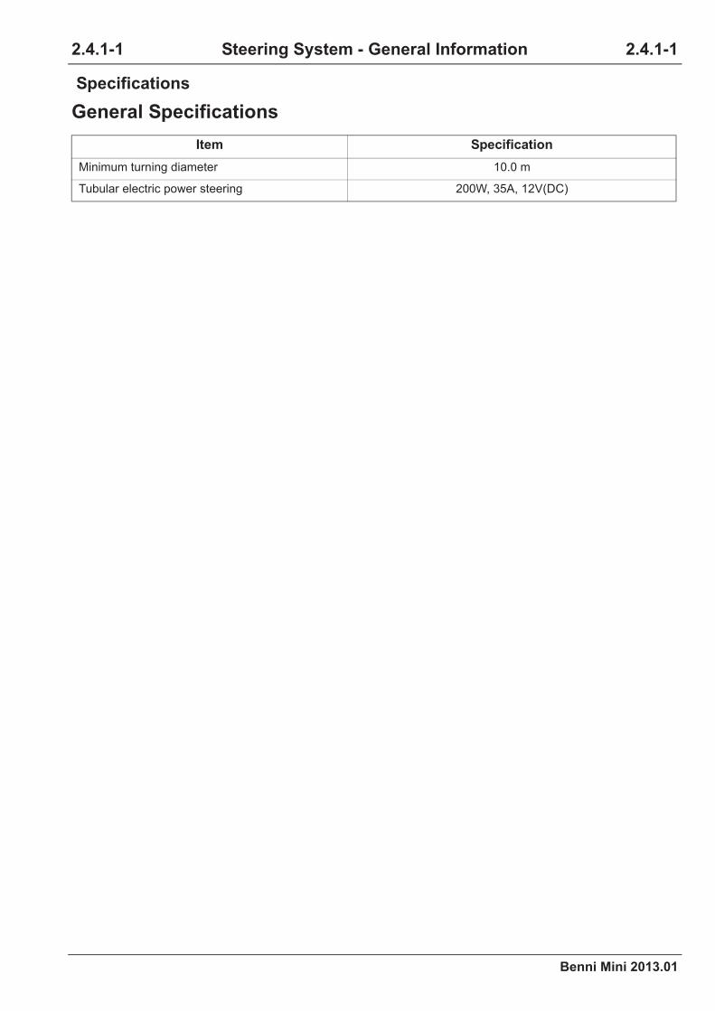
Benni Mini 2013.01
2.4.1-1 2.4.1-1Steering System - General Information
Specifications
General Specifications
Item Specification
Minimum turning diameter 10.0 m
Tubular electric power steering 200W, 35A, 12V(DC)
2.4.1 Steering System - General Information
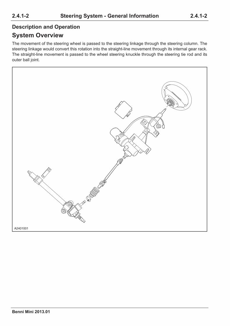
2.4.1-2
Benni Mini 2013.01
2.4.1-2Steering System - General Information
Description and Operation
System Overview
The movement of the steering wheel is passed to the steering linkage through the steering column. The
steering linkage would convert this rotation into the straight-line movement through its internal gear rack.
The straight-line movement is passed to the wheel steering knuckle through the steering tie rod and its
outer ball joint.
A2401001

Benni Mini 2013.01
2.4.1-3 2.4.1-3Steering System - General Information
Component Description
Steering Column
The steering column is equipped with a multi-direction steering wheel lock (or anti-theft lock) approved
by strict tests. The steering wheel is equipped with a safety lock. The steering column is equipped with
the steering power system, and the control module control the steering power motor to provide the steer-
ing power. The steering column and its top are fixed on the peripheral of the console.
The steering wheel is fixed on the steering column assembly by the retaining nut, and the steering pinion
connects the steering column by the flexible universal joint. The flexible universal joint is fixed on the pin-
ion by the retaining bolts and fixed on the steering column with the retaining bolts of the retainer and the
shaft locator assembly.
A2401002

2.4.1-4
Benni Mini 2013.01
2.4.1-4Steering System - General Information
Steering Linkage
The steering linkage is of the rack and gear design with the upper connecting to the steering column.
A2401003
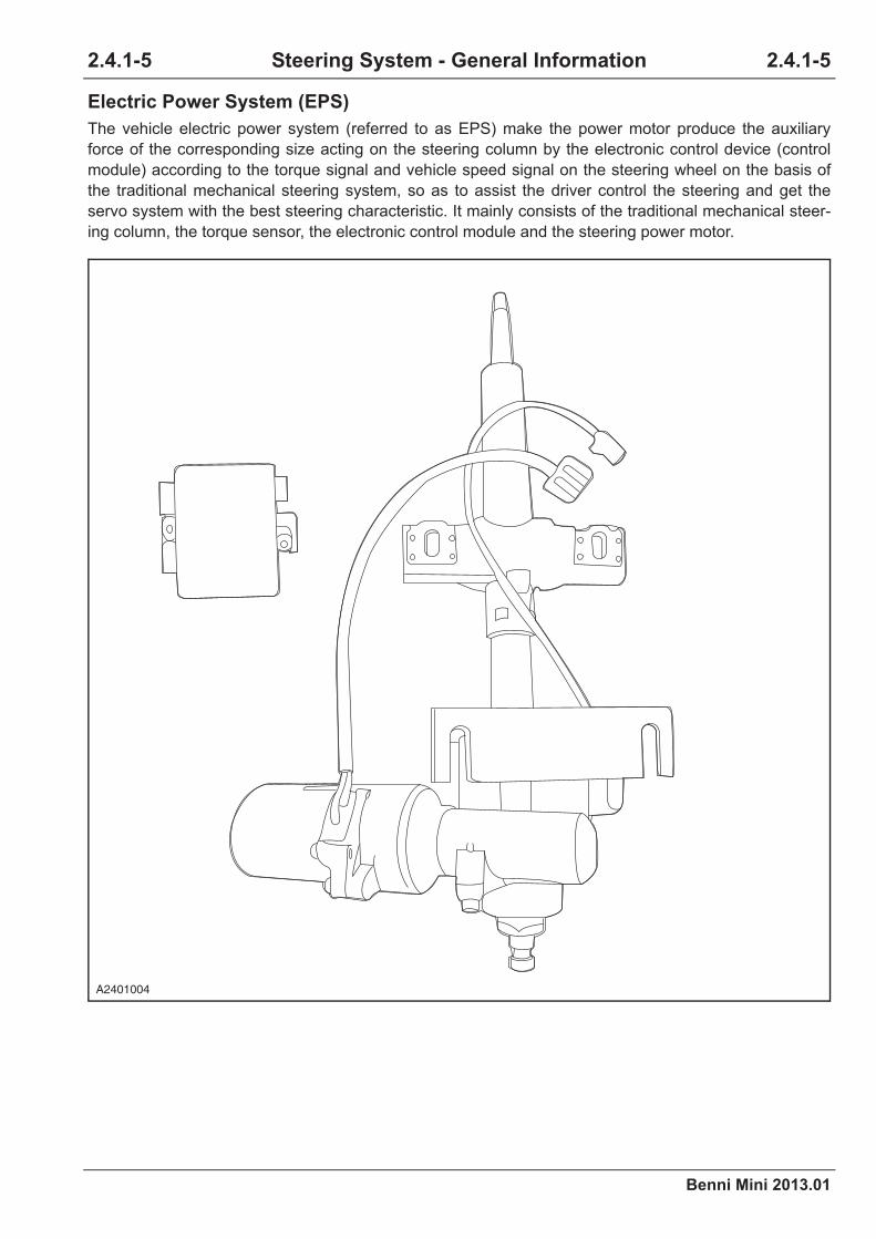
Benni Mini 2013.01
2.4.1-5 2.4.1-5Steering System - General Information
Electric Power System (EPS)
The vehicle electric power system (referred to as EPS) make the power motor produce the auxiliary
force of the corresponding size acting on the steering column by the electronic control device (control
module) according to the torque signal and vehicle speed signal on the steering wheel on the basis of
the traditional mechanical steering system, so as to assist the driver control the steering and get the
servo system with the best steering characteristic. It mainly consists of the traditional mechanical steer-
ing column, the torque sensor, the electronic control module and the steering power motor.
A2401004

2.4.1-6
Benni Mini 2013.01
2.4.1-6Steering System - General Information
Exploded View
Item Description Qty Item Description Qty
1 EPS module 1 6Steering tubular column cover assem-
bly clamp1
2 Multifunction steering wheel 1 7 Cotter pin 2
3 Steering column assembly 1 8 Nut 2
4 Steering lower shaft assembly 1 9 Steering gear assembly 1
5Steering tubular column cover assem-
bly1 10 Rack side bracket 1
8
7
6
5
4
3
10
8
7
2
9
1
A2401005

Benni Mini 2013.01
2.4.1-7 2.4.1-7Steering System - General Information
General Procedures
Steering Linkage Inspection
Inspect if the dust boot of the steering linkage is damaged, corroded or distorted. Ensure that the dust
boot is safe and reliable. If necessary, replace the dust boot or the clamp.
1. Park the vehicle on the dry and flat ground and pull the parking brake. Central the steering wheel.
2. Shut down the engine and hold the steering wheel tightly with hands. Rock the steering wheel to four
directions powerfully (do not turn steering wheel), inspect the wear of the steering column bearing
and the loose of the steering coupling, the steering wheel and the steering column. If any, inspect the
retaining bolt torque of the steering column, the coupling and the steering wheel. The steering
column can not be repaired, if necessary replace it.
Refer to: Steering Column (2.4.4 Steering Column, Removal and Installation).
3. If the steering linkage is damaged, replace it if necessary.
Refer to: Steering Column (2.4.4 Steering Column, Removal and Installation).
The steering column can not be repaired, replace it if necessary.
Refer to: Steering Column (2.4.4 Steering Column, Removal and Installation).
As the clearance of the steering linkage cannot be adjusted, replace it if necessary.
Steering Wheel Free Clearance Inspection
When the engine shuts down, inspect the steering wheel with the vehicle fixed on the forward ground.
Steering Wheel Free Clearance Range: 0-30 mm (0-1.2in.)
If the steering wheel does not move in the free clearance range, inspect as the following example, if any
defect is found, replace.
1. If the steering tie rod ball is worn.
2. If the lower ball joint is worn.
3. If the steering shaft joint is worn.
4. If the pinion or the gear and rack is worn or cracked.
5. If other components are loose.

2.4.1-8
Benni Mini 2013.01
2.4.1-8Steering System - General Information
Symptom Diagnosis and Testing
Inspection and Verification
1. Verify the customer's concern.
2. Visually inspect for obvious signs of
mechanical damage.
Visual Inspection Chart
3. If an obvious cause for an observed or
reported concern is found, correct the cause
before proceeding to the next step.
4. If the concern is not visually evident, verify
the symptom and refer to the Symptom Chart.
Mechanical Electrical
•Tire pressure
•Tie rod end
•Tie rod
•Front strut and spring
assembly
•Front suspension front
swing arm ball joint
•Front suspension front
swing arm bushing
•Retaining bolts on steer-
ing column shaft flexible
joint
•Wheel and Tire
•Steering gear sleeve
•Electric power steering
column
•EPS control module
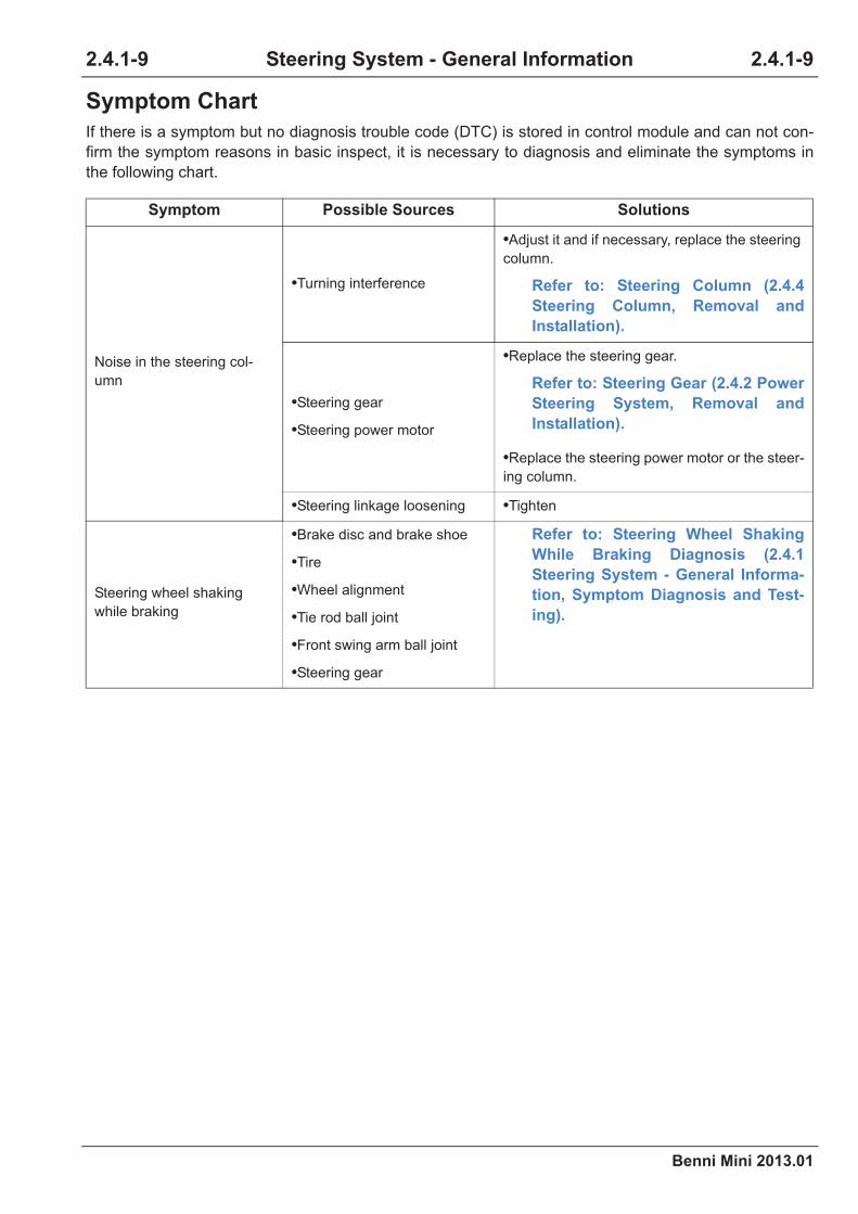
Benni Mini 2013.01
2.4.1-9 2.4.1-9Steering System - General Information
Symptom Chart
If there is a symptom but no diagnosis trouble code (DTC) is stored in control module and can not con-
firm the symptom reasons in basic inspect, it is necessary to diagnosis and eliminate the symptoms in
the following chart.
Symptom Possible Sources Solutions
Noise in the steering col-
umn
•Turning interference
•Adjust it and if necessary, replace the steering
column.
Refer to: Steering Column (2.4.4
Steering Column, Removal and
Installation).
•Steering gear
•Steering power motor
•Replace the steering gear.
Refer to: Steering Gear (2.4.2 Power
Steering System, Removal and
Installation).
•Replace the steering power motor or the steer-
ing column.
•Steering linkage loosening •Tighten
Steering wheel shaking
while braking
•Brake disc and brake shoe
•Tire
•Wheel alignment
•Tie rod ball joint
•Front swing arm ball joint
•Steering gear
Refer to: Steering Wheel Shaking
While Braking Diagnosis (2.4.1
Steering System - General Informa-
tion, Symptom Diagnosis and Test-
ing).

2.4.1-10
Benni Mini 2013.01
2.4.1-10Steering System - General Information
Abnormal steering return
function
•Too large inner friction of the
tie rod ball joint
•Replace the tie rod ball joint.
Refer to: Tie Rod Ball Joint (2.4.3
Steering Linkage, Removal and
Installation).
•The plug is too tight. •Pre-tighten it again.
•Steering tie rod and ball joint
defect
•Replace the tie rod ball joint.
Refer to: Tie Rod Ball Joint (2.4.3
Steering Linkage, Removal and
Installation).
•The fixation between the
steering gear and the frame is
loose
•Re-tighten
•Rack bends.
•Replace the steering gear.
Refer to: Steering Gear (2.4.2 Power
Steering System, Removal and
Installation).
•The gear bearing is dam-
aged.
•Replace the steering gear.
Refer to: Steering Gear (2.4.2 Power
Steering System, Removal and
Installation).
•Abnormal electric power
steering system
•The tire pressure is too low.
•Inspect and repair the electric power steering
system.
•Inflate the wheel.
•Incorrect wheel alignment
•Adjust the wheel alignment parameter to the
specified value.
Refer to: Wheel Alignment (2.1.1
Suspension System - General Infor-
mation, General Procedures).
Steering power failure
•Damaged electric power
steering column
•Damaged EPS control mod-
ule
•Damaged steering gear
•Seized suspension ball
Refer to: Steering Power Failure
Diagnosis (2.4.2 Electric Power
Steering, Symptom Diagnosis and
Testing).
Symptom Possible Sources Solutions

Benni Mini 2013.01
2.4.1-11 2.4.1-11Steering System - General Information
The steering clearance
between the steering
wheels is too large and the
steering wheel is off the
center position.
•Damaged electric power
steering column
•Replace the electric power steering column.
Refer to: Steering Column (2.4.4
Steering Column, Removal and
Installation)
•The bolts on the steering
gear is loose.•Re-tighten
•The ball bolts on the steering
tie rod assembly are worn or
loose.
•Re-tighten and replace as necessary.
Refer to: Tie Rod Ball Joint (2.4.3
Steering Linkage, Removal and
Installation).
Squeak between the rack
and the gear
•The steering gear mounting
bolts are loose.•Re-tighten
•The tie rod ball is loose. •Re-tighten
•The tie rod ball is worn and
aging.
•Replace the tie rod ball joint.
Refer to: Tie Rod Ball Joint (2.4.3
Steering Linkage, Removal and
Installation).
Symptom Possible Sources Solutions
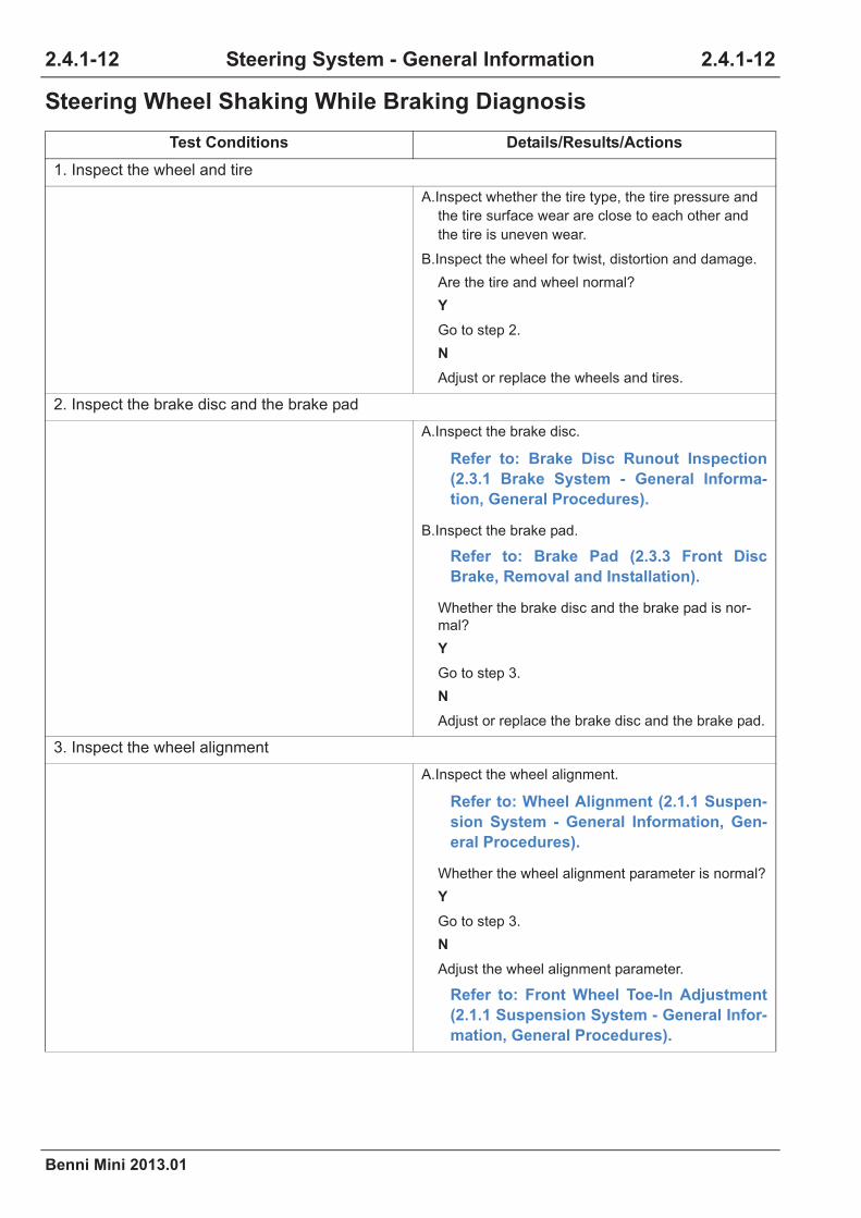
2.4.1-12
Benni Mini 2013.01
2.4.1-12Steering System - General Information
Steering Wheel Shaking While Braking Diagnosis
Test Conditions Details/Results/Actions
1. Inspect the wheel and tire
A.Inspect whether the tire type, the tire pressure and
the tire surface wear are close to each other and
the tire is uneven wear.
B.Inspect the wheel for twist, distortion and damage.
Are the tire and wheel normal?
Y
Go to step 2.
N
Adjust or replace the wheels and tires.
2. Inspect the brake disc and the brake pad
A.Inspect the brake disc.
Refer to: Brake Disc Runout Inspection
(2.3.1 Brake System - General Informa-
tion, General Procedures).
B.Inspect the brake pad.
Refer to: Brake Pad (2.3.3 Front Disc
Brake, Removal and Installation).
Whether the brake disc and the brake pad is nor-
mal?
Y
Go to step 3.
N
Adjust or replace the brake disc and the brake pad.
3. Inspect the wheel alignment
A.Inspect the wheel alignment.
Refer to: Wheel Alignment (2.1.1 Suspen-
sion System - General Information, Gen-
eral Procedures).
Whether the wheel alignment parameter is normal?
Y
Go to step 3.
N
Adjust the wheel alignment parameter.
Refer to: Front Wheel Toe-In Adjustment
(2.1.1 Suspension System - General Infor-
mation, General Procedures).

Benni Mini 2013.01
2.4.1-13 2.4.1-13Steering System - General Information
4. Inspect the tie rod ball joint and the front swing arm ball joint
A.Lift the vehicle.
Refer to: Lifting (1.1.3 Traction and Lifting,
Description and Operation).
B.Inspect the tie rod ball joint and the front swing arm
ball joint.
Is the ball joint normal?
Y
Replace the steering gear.
Refer to: Steering Gear (2.4.2 Power
Steering System, Removal and Installa-
tion).
N
Replace the tie rod ball joint .
Refer to: Tie Rod Ball Joint (2.4.3 Steering
Linkage, Removal and Installation).
Replace the front swing arm ball joint .
Refer to: Front Swing Arm and Arm Ball
Joint Pin (2.1.2 Front Suspension,
Removal and Installation).
Test Conditions Details/Results/Actions

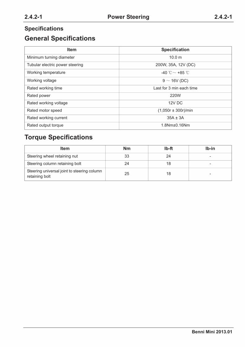
Benni Mini 2013.01
2.4.2-1 2.4.2-1Power Steering
Specifications
General Specifications
Torque Specifications
Item Specification
Item Nm lb-ft lb-in
2.4.2 Power Steering System

2.4.2-2
Benni Mini 2013.01
2.4.2-2Power Steering
Description and Operation
System Overview
Component Description
1. EPS Controller
Item Description Item Description
1
2
A2402001

Benni Mini 2013.01
2.4.2-3 2.4.2-3Power Steering
2. Motor
3. Torque Sensor
4. VSS (Vehicle Speed Sensor)
5. Engine Speed Signal

2.4.2-4
Benni Mini 2013.01
2.4.2-4Power Steering
General Procedures
Steering Force Inspection
1.
2.
3.
4.
Steering Force: more than 35N (3.5kg)

Benni Mini 2013.01
2.4.2-5 2.4.2-5Power Steering
Symptom Diagnosis and Testing
Inspection and Verification
1.
2.
Visual Inspection Chart
3.
4.
5.
General Equipment
Mechanical Electrical
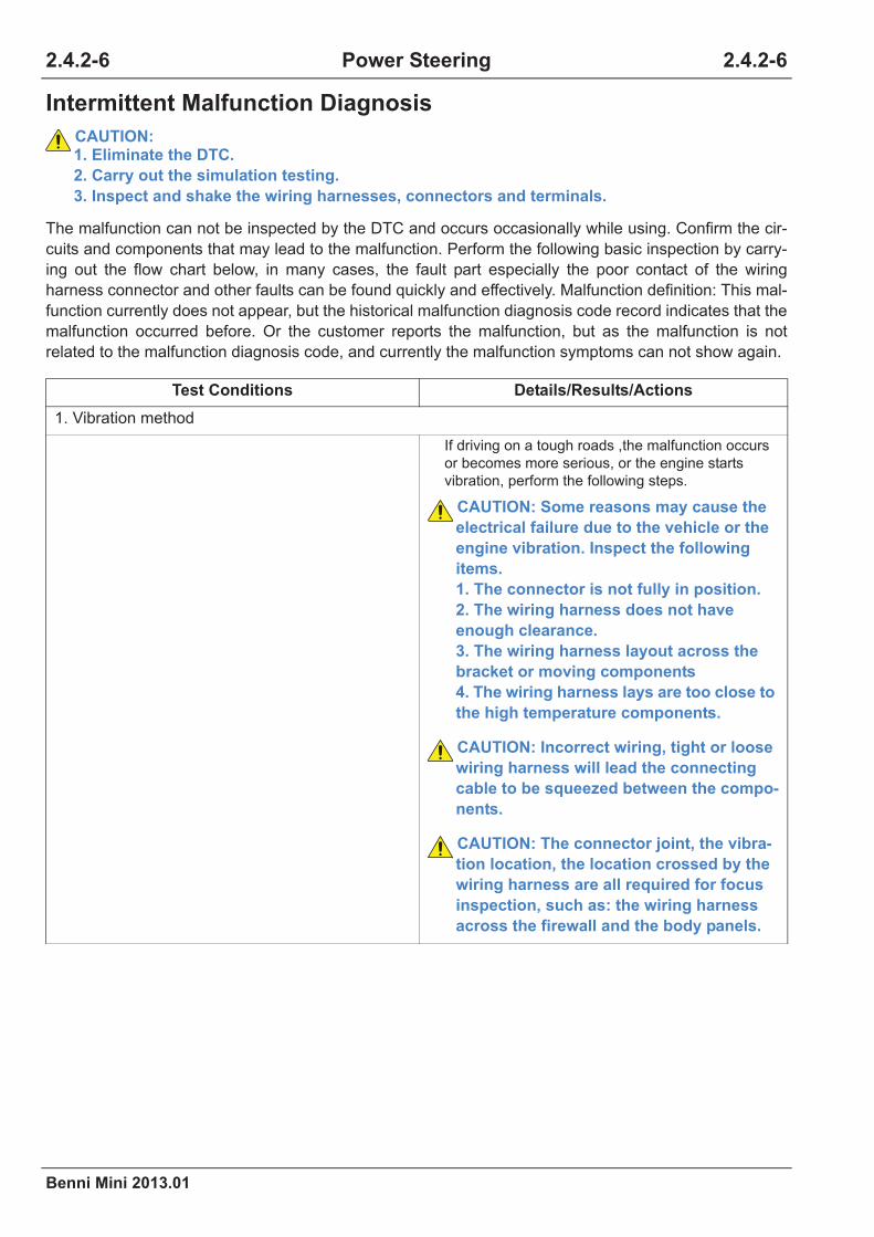
2.4.2-6
Benni Mini 2013.01
2.4.2-6Power Steering
Intermittent Malfunction Diagnosis
CAUTION: 1. Eliminate the DTC.
2. Carry out the simulation testing.
3. Inspect and shake the wiring harnesses, connectors and terminals.
Test Conditions Details/Results/Actions
CAUTION: Some reasons may cause the
electrical failure due to the vehicle or the
engine vibration. Inspect the following
items.
1. The connector is not fully in position.
2. The wiring harness does not have
enough clearance.
3. The wiring harness layout across the
bracket or moving components
4. The wiring harness lays are too close to
the high temperature components.
CAUTION: Incorrect wiring, tight or loose
wiring harness will lead the connecting
cable to be squeezed between the compo-
nents.
CAUTION: The connector joint, the vibra-
tion location, the location crossed by the
wiring harness are all required for focus
inspection, such as: the wiring harness
across the firewall and the body panels.
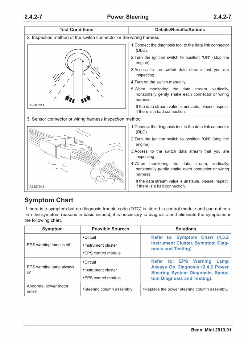
Benni Mini 2013.01
2.4.2-7 2.4.2-7Power Steering
Symptom Chart
Symptom Possible Sources Solutions
•
•
•
Refer to: Symptom Chart (4.3.2
Instrument Cluster, Symptom Diag-
nosis and Testing).
•
•
•
Refer to: EPS Warning Lamp
Always On Diagnosis (2.4.2 Power
Steering System Diagnosis, Symp-
tom Diagnosis and Testing).
• •
Test Conditions Details/Results/Actions
A2307014
A2307015
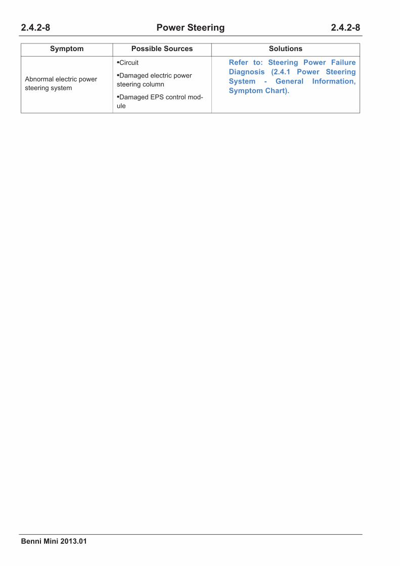
2.4.2-8
Benni Mini 2013.01
2.4.2-8Power Steering
•
•
•
Refer to: Steering Power Failure
Diagnosis (2.4.1 Power Steering
System - General Information,
Symptom Chart).
Symptom Possible Sources Solutions
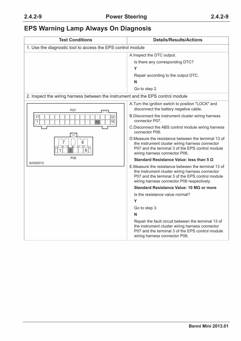
Benni Mini 2013.01
2.4.2-9 2.4.2-9Power Steering
EPS Warning Lamp Always On Diagnosis
Test Conditions Details/Results/Actions
Y
N
Standard Resistance Value: less than 5
Standard Resistance Value: 10 M or more
Y
N
P07
P06
32
16
17
131
87
61 3
A2402012

2.4.2-10
Benni Mini 2013.01
2.4.2-10Power Steering
Standard Voltage Value: 11~14 V
Standard Resistance Value: less than 5
Y
Refer to: EPS Control Module (2.4.2
Power Steering System, Removal and
Installation).
N
Refer to: Instrument Cluster (4.3.2 Instru-
ment Cluster, Removal and Installation).
Test Conditions Details/Results/Actions
P06
87
61
A2402013
P06
87
61
A2402014

Benni Mini 2013.01
2.4.2-11 2.4.2-11Power Steering
DTC Diagnosis and Testing
Control Module Terminal List
Terminal ID WiringTerminal Descrip-
tionStatus
87
61
A2402015

2.4.2-12
Benni Mini 2013.01
2.4.2-12Power Steering
DTC Code List
Fault Diagnostic Tool Can Not Communicate With Vehicle Diagno-
sis
CAUTION: The short circuit of the internal module may also cause the fault.
Refer to: Diagnostic Tool Can Not Communicate With ECM Diagnosis (4.3.13 On-Board Net-
work, Symptom Diagnosis and Testing).
Malfunction Description

Benni Mini 2013.01
2.4.2-13 2.4.2-13Power Steering
DTC Diagnosis Chart
Malfunction Description Diagnosis Procedures
Refer to: C1111,
C1113, C1114, C1115
Refer to: C1121,
C1123, C1124
Refer to: C1122
Refer to: C1141,
C1142, C1143, C1144,
C1145, C1151
Refer to: C1152,
C1154, C1155
2.4.2-14
Benni Mini 2013.01
2.4.2-14Power Steering
DTC C1111, C1113, C1114, C1115
1. Fault Code Description
2. Possible Sources
3. Diagnosis Procedures
Fault Code Description Definition
Fault
CodeTest Policy
Installation Conditions
(Control Tactics)Fault
Test Conditions Details/Results/Actions
Y
N

Benni Mini 2013.01
2.4.2-15 2.4.2-15Power Steering
Y
N
Refer to: Intermittent Fault Diagnosis
(2.4.3 Steering Linkage Diagnosis, Symp-
tom Diagnosis and Testing).
Y
N
Y
N
Test Conditions Details/Results/Actions

2.4.2-16
Benni Mini 2013.01
2.4.2-16Power Steering
DTC C1121, C1123, C1124
1. Fault Code Description
Standard Voltage Value: 11~14 V
Standard Resistance Value: less than 5
Y
N
Refer to: EPS Control Module (2.4.2
Power Steering System, Removal and
Installation).
Fault Code Description Definition
Test Conditions Details/Results/Actions
P06
87
61
A2402013
P06
87
61
A2402014

Benni Mini 2013.01
2.4.2-17 2.4.2-17Power Steering
2. Possible Sources
3. Diagnosis Procedures
Fault
CodeTest Policy
Installation Conditions
(Control Tactics)Fault Part
Test Conditions Details/Results/Actions
Y
N
Y
N
Refer to: Intermittent Fault Diagnosis
(2.4.3 Steering Linkage Diagnosis, Symp-
tom Diagnosis and Testing).

2.4.2-18
Benni Mini 2013.01
2.4.2-18Power Steering
Standard Resistance Value: less than 5
Y
N
Test Conditions Details/Results/Actions
C26
1 3
P06
87
651
A2402016

Benni Mini 2013.01
2.4.2-19 2.4.2-19Power Steering
Standard Voltage Value: 11~14 V
Standard Resistance Value: less than 5
Y
N
Y
N
Test Conditions Details/Results/Actions
1 3
C26
A2402017
1 32
C26
A2402018

2.4.2-20
Benni Mini 2013.01
2.4.2-20Power Steering
Standard Voltage Value: 11~14 V
Standard Resistance Value: less than 5
Y
N
Refer to: EPS Control Module (2.4.2
Power Steering System, Removal and
Installation).
Test Conditions Details/Results/Actions
P06
87
61
A2402013
P06
87
61
A2402014

Benni Mini 2013.01
2.4.2-21 2.4.2-21Power Steering
DTC C1122
1. Fault Code Description
2. Possible Sources
3. Diagnosis Procedures
Fault Code Description Definition
Fault
CodeTest Policy
Installation Conditions
(Control Tactics)Fault
Test Conditions Details/Results/Actions
Y
N
Y
N
Refer to: Intermittent Fault Diagnosis
(2.4.3 Steering Linkage Diagnosis, Symp-
tom Diagnosis and Testing).

2.4.2-22
Benni Mini 2013.01
2.4.2-22Power Steering
Standard Resistance Value: less than 5
Y
N
Test Conditions Details/Results/Actions
E01a
P06
87
641
3
5 4
2 1
86
25
44
63
24
43
62
81
A2402019

Benni Mini 2013.01
2.4.2-23 2.4.2-23Power Steering
Standard Voltage Value: 11~14 V
Standard Resistance Value: less than 5
Y
N
Refer to: EPS Control Module (2.4.2
Power Steering System, Removal and
Installation).
Test Conditions Details/Results/Actions
P06
87
61
A2402013
P06
87
61
A2402014

2.4.2-24
Benni Mini 2013.01
2.4.2-24Power Steering
DTC C1141, C1142, C1143, C1144, C1145, C1151
1. Fault Code Description
2. Possible Sources
3. Diagnosis Procedures
Fault Code Description Definition
Fault
CodeTest Policy
Installation Conditions
(Control Tactics)Fault Part
Test Conditions Details/Results/Actions
Y
N

Benni Mini 2013.01
2.4.2-25 2.4.2-25Power Steering
Y
N
Refer to: Intermittent Fault Diagnosis
(2.4.3 Steering Linkage Diagnosis, Symp-
tom Diagnosis and Testing).
Y
N
Refer to: Steering Column Assembly
(2.4.4 Steering Column, Removal and
Installation).
Test Conditions Details/Results/Actions
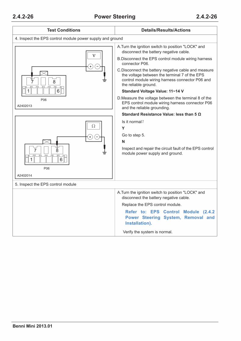
2.4.2-26
Benni Mini 2013.01
2.4.2-26Power Steering
Standard Voltage Value: 11~14 V
Standard Resistance Value: less than 5
Y
N
Refer to: EPS Control Module (2.4.2
Power Steering System, Removal and
Installation).
Test Conditions Details/Results/Actions
P06
87
61
A2402013
P06
87
61
A2402014

Benni Mini 2013.01
2.4.2-27 2.4.2-27Power Steering
DTC C1152, C1154, C1155
1. Fault Code Description
2. Possible Sources
3. Diagnosis Procedures
Fault Code Description Definition
Fault
CodeTest Policy
Installation Conditions
(Control Tactics)Fault Part
Test Conditions Details/Results/Actions
Y
N
Y
N
Refer to: Intermittent Fault Diagnosis
(2.4.3 Steering Linkage Diagnosis, Symp-
tom Diagnosis and Testing).

2.4.2-28
Benni Mini 2013.01
2.4.2-28Power Steering
Standard Voltage Value: 11~14 V
Standard Resistance Value: less than 5
Y
N
Refer to: EPS Control Module (2.4.2
Power Steering System, Removal and
Installation).
Test Conditions Details/Results/Actions
P06
87
61
A2402013
P06
87
61
A2402014
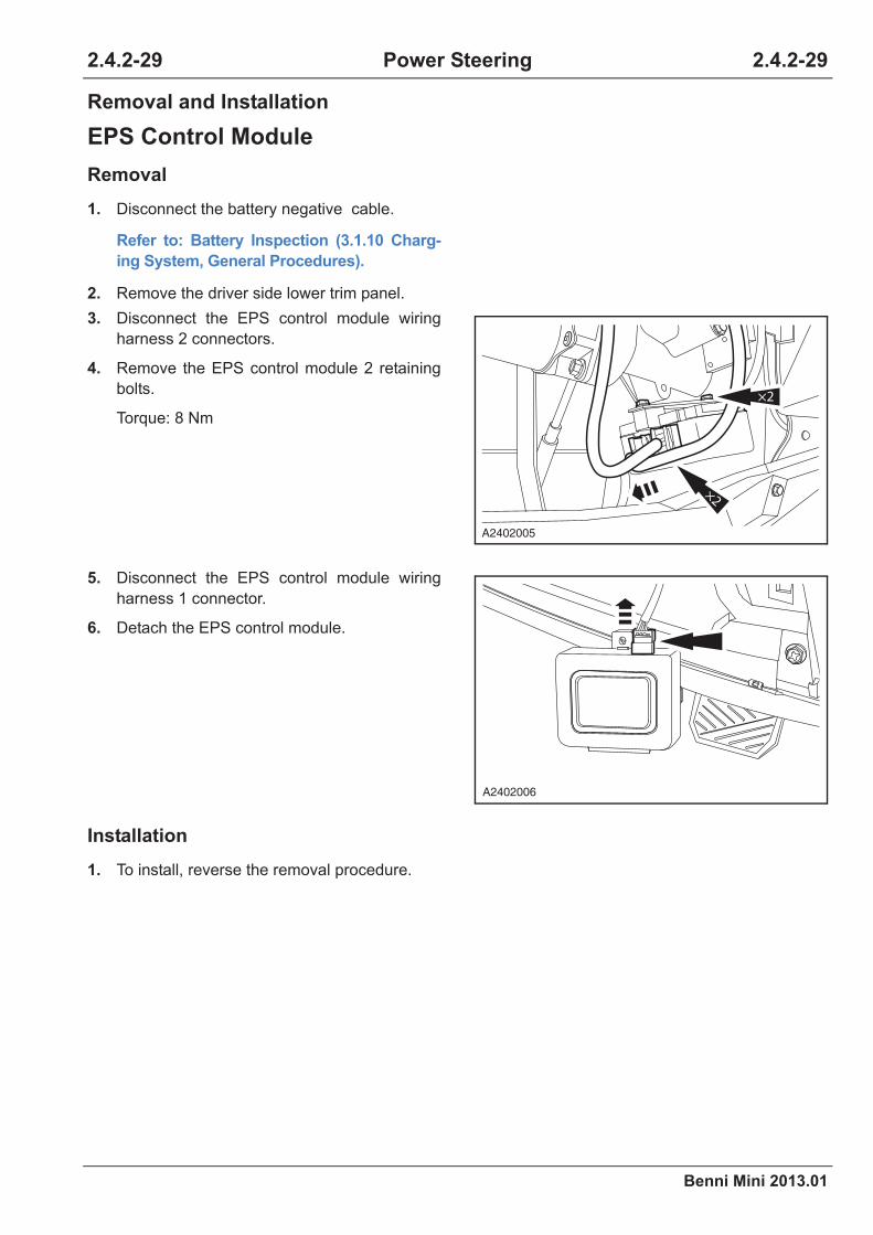
Benni Mini 2013.01
2.4.2-29 2.4.2-29Power Steering
Removal and Installation
EPS Control Module
Removal
Installation
1. Disconnect the battery negative cable.
Refer to: Battery Inspection (3.1.10 Charg-
ing System, General Procedures).
2. Remove the driver side lower trim panel.
3. Disconnect the EPS control module wiring
harness 2 connectors.
4. Remove the EPS control module 2 retaining
bolts.
Torque: 8 Nm
5. Disconnect the EPS control module wiring
harness 1 connector.
6. Detach the EPS control module.
1. To install, reverse the removal procedure.
×2
×2
A2402005
A2402006

2.4.2-30
Benni Mini 2013.01
2.4.2-30Power Steering
Steering Gear
Removal
1. Remove the two front wheels.
Refer to: Wheel and Tire (2.1.4 Wheels and
Tires, Removal and Installation).
2. Lift the vehicle.
Refer to: Lifting (1.1.3 Traction and Lifting,
Description and Operation).
3. Remove the tie rod ball joint and the steering
knuckle connection.
Refer to: Tie Rod Ball Joint (2.4.3 Steering
Gear, Removal and Installation).
4. Remove the steering column cover assembly
clamp and detach down the steering column
cover assembly.
5. Remove the steering gear and steering
column retaining bolt.
Torque: 25 Nm
CAUTION: Make the two front wheels in
the straight-ahead state and the steering
wheel in the middle, and lock the steering
wheel with the steering wheel lock to
avoid damaging the clock spring before
disconnecting the power steering gear
and steering column connection.
A2402010
A2402007

Benni Mini 2013.01
2.4.2-31 2.4.2-31Power Steering
Installation
6. Remove the front subframe assembly.
1.Remove the front subframe retaining nut.
Torque: 50 Nm
2.Remove the front subframe retaining bolt.
3.Release the front subframe retaining bolt
but do not detach it.
Torque: 50 Nm
7. Remove four retaining bolts on the steering
gear and detach the steering gear.
Torque: 60 Nm
1. To install, reverse the removal procedure.
CAUTION: Ensure the spline is meshed
properly when installing the steering gear
and steering colunm connection.
CAUTION: Inspect the front toe-in and
adjust it accordingly, and make four-wheel
alignment.
2
3
1
A2402008
×2×2
A2402009


Benni Mini 2013.01
2.4.3-1 2.4.3-1Steering Linkage
Specifications
Torque Specifications
Item Nm lb-ft lb-in
Steering tie rod ball joint retaining nut 43 32 -
Tie rod ball joint locknut 55 41 -
Wheel nut 85 63 -
2.4.3 Steering Linkage

2.4.3-2
Benni Mini 2013.01
2.4.3-2Steering Linkage
Description and Operation
System Overview
The steering tie rod is connected with the steering linkage. The following components transfer the steer-
ing linkage movement to the wheel:
• Steering tie rod
• Tie rod ball joint
• Steering knuckle
The steering tie rod ball joint is connected with the tie rod with the retaining nut.
Item Description Item Description
1 Steering tubular column cover assembly 6 Steering linkage dust boot
2Steering tubular column cover assembly
clamp7 Inner tie rod joint assembly
3 Steering gear assembly 8 Cotter pin
4 Steering rod retaining washer 9 Tie rod ball joint retaining nut
5 Steering linkage dust boot clamp 10 Tie rod ball joint
1
9
8
2
3
10
4 5
6
7
A2403006
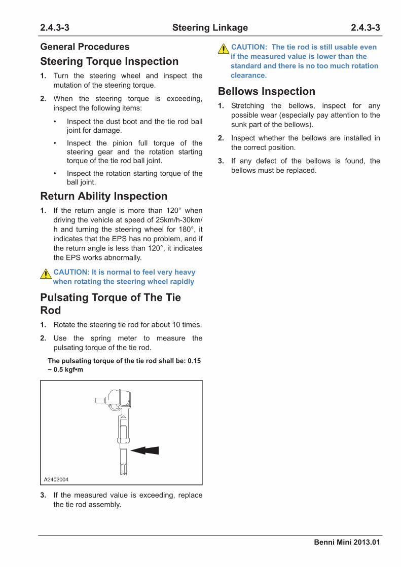
Benni Mini 2013.01
2.4.3-3 2.4.3-3Steering Linkage
General Procedures
Steering Torque Inspection
1. Turn the steering wheel and inspect the
mutation of the steering torque.
2. When the steering torque is exceeding,
inspect the following items:
• Inspect the dust boot and the tie rod ball
joint for damage.
• Inspect the pinion full torque of the
steering gear and the rotation starting
torque of the tie rod ball joint.
• Inspect the rotation starting torque of the
ball joint.
Return Ability Inspection
1. If the return angle is more than 120° when
driving the vehicle at speed of 25km/h-30km/
h and turning the steering wheel for 180°, it
indicates that the EPS has no problem, and if
the return angle is less than 120°, it indicates
the EPS works abnormally.
CAUTION: It is normal to feel very heavy
when rotating the steering wheel rapidly
Pulsating Torque of The Tie
Rod
1. Rotate the steering tie rod for about 10 times.
2. Use the spring meter to measure the
pulsating torque of the tie rod.
The pulsating torque of the tie rod shall be: 0.15
~ 0.5 kgf•m
3. If the measured value is exceeding, replace
the tie rod assembly.
CAUTION: The tie rod is still usable even
if the measured value is lower than the
standard and there is no too much rotation
clearance.
Bellows Inspection
1. Stretching the bellows, inspect for any
possible wear (especially pay attention to the
sunk part of the bellows).
2. Inspect whether the bellows are installed in
the correct position.
3. If any defect of the bellows is found, the
bellows must be replaced.
A2402004

2.4.3-4
Benni Mini 2013.01
2.4.3-4Steering Linkage
Symptom Diagnosis and Testing
Refer to: Symptom Chart (2.4.1 Steering
System - General Information, Symptom
Diagnose and Testing).

Benni Mini 2013.01
2.4.3-5 2.4.3-5Steering Linkage
Removal and Installation
Tie Rod Ball Joint
Removal
Special Tool
Tie Rod Ball Joint Puller
CA201-001
1. Remove the front wheels.
Refer to: Wheel and Tire (2.1.4 Wheels and
Tires, Removal and Installation).
2. Lift the vehicle.
Refer to: Lifting (1.1.3 Traction and Lifting,
Description and Operation).
3. Release the tie rod ball joint.
1.Remove the retaining nut.
Torque: 42.5 Nm
2. Remove the cotter pin.
3.Remove the retaining nut.
Torque: 42.5 Nm
4. Remove the tie rod ball joint.
1.Remove the tie rod ball joint with a special
tool.
Special Tool: CA201-001
2.Screw off the retaining nut.
CAUTION: When the tie rod ball joint is
separated from the steering knuckle ball
joint connection, protect the oil seal.
CA201-001
2
1
3
A2403001
CA201-001
A2403002
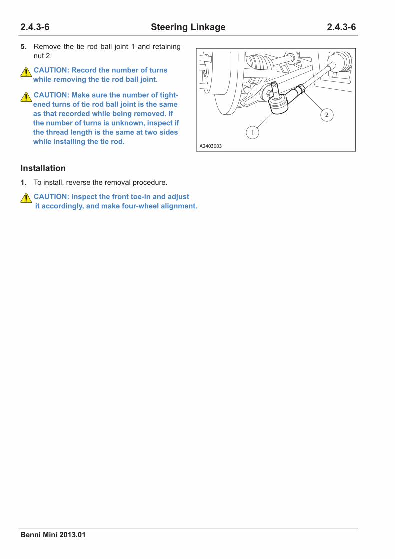
2.4.3-6
Benni Mini 2013.01
2.4.3-6Steering Linkage
Installation
1. To install, reverse the removal procedure.
CAUTION: Inspect the front toe-in and adjust
it accordingly, and make four-wheel alignment.
5. Remove the tie rod ball joint 1 and retaining
nut 2.
CAUTION: Record the number of turns
while removing the tie rod ball joint.
CAUTION: Make sure the number of tight-
ened turns of tie rod ball joint is the same
as that recorded while being removed. If
the number of turns is unknown, inspect if
the thread length is the same at two sides
while installing the tie rod.
1
2
A2403003

Benni Mini 2013.01
2.4.3-7 2.4.3-7Steering Linkage
Steering Gear Dust Boot
Removal
Installation
1. To install, reverse the removal procedure.
CAUTION: Inspect the front toe-in and adjust
it accordingly, and make four-wheel alignment.
1. Lift the vehicle.
Refer to: Lifting (1.1.3 Traction and Lifting,
Description and Operation).
2. Remove the tie rod ball joint.
Refer to: Tie Rod Ball Joint (2.4.3 Steering
Gear, Removal and Installation).
CAUTION: Make sure the tie rod is clean
before removal of the dust boot.
3. Remove the steering gear dust boot.
1.Remove the inner clamp of dust boot.
2.Remove the outer clamp of dust boot.
3.Detach the dust boot on the tie rod.
22
A2403004


Benni Mini 2013.01
2.4.4-1 2.4.4-1Steering Column
Specifications
Torque Specifications
Item Nm lb-ft lb-in
Steering wheel retaining nut 33 24 -
Steering column retaining nut 24 18 -
Steering universal joint to steering column
retaining bolt25 18 -
2.4.4 Steering Column

2.4.4-2
Benni Mini 2013.01
2.4.4-2Steering Column
Description and Operation
System Overview
The steering wheel is fixed on the steering column assembly by the retaining bolts. The power steering
system is installed on the steering column, and the control module controls the power steering motor to
provide the power while the steering pinion connects with the steering column through the flexible univer-
sal joint. The flexible universal joint is fixed on the pinion by the retaining bolts and fixed on the steering
column with the retaining bolts of the retainer and the shaft locator assembly.
Item Description Item Description
1 Steering lower shaft assembly 2 Steering column assembly
2
1
A2404001

Benni Mini 2013.01
2.4.4-3 2.4.4-3Steering Column
Symptom Diagnosis and Testing
Refer to: Symptom Chart (2.4.1 Steering
System - General Information, Symptom
Diagnosis and Testing).
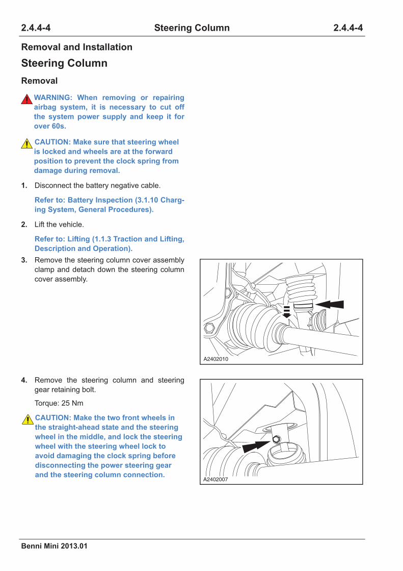
2.4.4-4
Benni Mini 2013.01
2.4.4-4Steering Column
Removal and Installation
Steering Column
Removal
WARNING: When removing or repairing
airbag system, it is necessary to cut off
the system power supply and keep it for
over 60s.
CAUTION: Make sure that steering wheel
is locked and wheels are at the forward
position to prevent the clock spring from
damage during removal.
1. Disconnect the battery negative cable.
Refer to: Battery Inspection (3.1.10 Charg-
ing System, General Procedures).
2. Lift the vehicle.
Refer to: Lifting (1.1.3 Traction and Lifting,
Description and Operation).
3. Remove the steering column cover assembly
clamp and detach down the steering column
cover assembly.
4. Remove the steering column and steering
gear retaining bolt.
Torque: 25 Nm
CAUTION: Make the two front wheels in
the straight-ahead state and the steering
wheel in the middle, and lock the steering
wheel with the steering wheel lock to
avoid damaging the clock spring before
disconnecting the power steering gear
and the steering column connection.
A2402010
A2402007

Benni Mini 2013.01
2.4.4-5 2.4.4-5Steering Column
5. Remove the driver air bag and the steering
wheel.
Refer to: Airbag (4.2.1 Airbag System,
Driver Airbag and Steering Wheel
Removal and Installation).
6. Remove the driver side lower protection
panel.
7. Remove two retaining screws on the steering
lock cover.
8. Remove three retaining screws on the
steering lock cover side and detach the
steering lock cover.
9. Remove the lighting combination switch.
Refer to: Lighting Combination Switch
(4.3.7 Lighting System, Removal and
Installation).
10. Remove the wiper combination switch.
Refer to: Wiper Combination Switch (4.3.8
Wipers and Washers, Removal and Instal-
lation).
11. Remove the clock spring.
12. Disconnect the ignition switch wiring harness
connector.
13. Remove the EPS control module.
Refer to: EPS Control Module (2.4.2 Power
Steering System, Removal and Installa-
tion).
A2404002
×3
A2404003
A2404004

2.4.4-6
Benni Mini 2013.01
2.4.4-6Steering Column
Installation
14. Remove two nuts fixed on the steering
column and the middle instrument cluster
bracket.
Torque: 25 Nm
15. Remove two nuts fixed on the steering
column and the upper instrument cluster
bracket.
Torque: 25 Nm
1. To install, reverse the removal procedure.
CAUTION: When installing steering col-
umn retaining bolt, do not fully tighten it
until all bolts are mounted to the suitable
positions; then tighten the bolts with the
specified torque.
CAUTION: Ensure the spline is meshed
properly when installing the steering gear
and the steering column connection.
CAUTION: Inspect the front toe-in and
adjust it accordingly, and make four-wheel
alignment.
A2404006
A2404007