beren yilmaz master thesis - middle east technical … · two different concepts and design...
TRANSCRIPT

i
AN ANALYTICAL AND EXPERIMENTAL STUDY ON PILED RAFT FOUNDATIONS
A THESIS SUBMITTED TO THE GRADUATE SCHOOL OF NATURAL AND APPLIED SCIENCES
OF MIDDLE EAST TECHNICAL UNIVERSITY
BY
BEREN YILMAZ
IN PARTIAL FULFILLMENT OF THE REQUIREMENTS FOR
THE DEGREE OF MASTER OF SCIENCE IN
CIVIL ENGINEERING
FEBRUARY 2010
ii
Approval of the thesis:
AN ANALYTICAL AND EXPERIMENTAL STUDY ON PILED RAFT FOUNDATIONS
submitted by BEREN YILMAZ in partial fulfillment of the requirements for the degree of Master of Science in Civil Engineering Department, Middle East Technical University by,
Prof. Dr. Canan ÖZGEN _____________________ Dean, Graduate School of Natural and Applied Sciences
Prof. Dr. Güney ÖZCEBE _____________________ Head of Department, Civil Engineering
Prof. Dr. M. Ufuk ERGUN Supervisor, Civil Engineering Dept., METU _____________________
Examining Committee Members:
Prof. Dr. Orhan EROL _____________________ Civil Engineering Dept., METU
Prof. Dr. M. Ufuk ERGUN _____________________ Civil Engineering Dept., METU
Prof. Dr. Erdal ÇOKÇA _____________________ Civil Engineering Dept., METU
Asst. Prof. Dr. Nejan HUVAJ SARIHAN _____________________ Civil Engineering Dept., METU
Yük. Müh. A. Mengüç ÜNVER _____________________ Argem Geoteknik Müh. Müş. Ltd. Şti. Date: 03.02.2010

iii
I hereby declare that all information in this document has been obtained and
presented in accordance with academic rules and ethical conduct. I also declare
that, as required by these rules and conduct, I have fully cited and referenced
all material and results that are not original to this work.
Name, Last name : Beren YILMAZ
Signature :

iv
ABSTRACT
AN ANALYTICAL AND EXPERIMENTAL STUDY ON PILED RAFT
FOUNDATIONS
YILMAZ, Beren
M.S., Department of Civil Engineering
Superviser: Prof. Dr. Mehmet Ufuk ERGUN
February 2010, 119 pages
Two different concepts and design procedures namely settlement reducing piles and
piled raft foundations have been studied independently in this thesis.
A laboratory study is conducted on model rafts with differing number of model
settlement reducing piles. Pile length, pile diameter, type of soil and size of raft are
kept constant and settlements are measured under sustained loading. Remolded
kaolin is consolidated under controlled stresses before tests are performed in model
boxes. The tests are conducted under two sustained loadings of 75 kPa and 40 kPa.
0(raft), 16 and 49 number of piles are used. During the tests, all of the skin friction is
mobilized. Several tests are conducted for each combination to see the variability. It
is concluded that increasing the pile number beyond an optimum value is inefficient

v
as far as the amount of settlement is considered. Also an analytical procedure has
been followed to calculate settlements with increasing number of piles.
In the second part of this thesis, finite element analyse have been performed on a
piled raft foundation model, using Plaxis 3D Foundation Engineering software. This
analyse are supported with analytical methods. The piled raft model is loaded with
450 kPa raft pressure. The studies are conducted in two sets in which different pile
lengths are used; 25 m and 30 m respectively. The numbers of piles are increased
from 63 to 143. All other parameters are kept constant. The results showed that again
an optimum number of piles will be sufficient to reduce the settlement to the
acceptable level. The analytical methods indicate a similar behavior. The comparison
and results are presented in the study.
Keywords: piled raft systems, settlement reducing piles, model tests, settlement of
pile groups
vi
ÖZ
KAZIK-RADYE SİSTEMLERİN ANALİTİK VE DENEYSEL OLARAK
İNCELENMESİ
YILMAZ, Beren
Yüksek Lisans, İnşaat Mühendisliği Bölümü
Tez Yöneticisi: Prof. Dr. Mehmet Ufuk ERGUN
Şubat 2010, 119 sayfa
Bu tez kapsamında, oturma azaltıcı kazıklar ve kazık-radye sistemleri olmak üzere,
iki farklı konsept ve tasarım sistemi üzerinde, birbirlerinden bağımsız olarak
çalışılmıştır.
Farklı sayıda oturma azaltıcı model kazık içeren modeller üzerinde laboratuvar
deneyleri yapılmıştır. Kazık boyu, çapı, zemin tipi ve radye boyutları sabit bırakılmış
ve oturmalar sürekli yükleme altında ölçülmüştür. Testlerin yapılmasından önce,
yoğurulmuş kaolin tipi kil, model kutularda, kontrollü basınç altında konsolide
edilmiştir. Deneylerde, 75 kPa ve 40 kPa olmak üzere, iki değerde sürekli yükleme
yapılmıştır. Kazık sayıları 0, 16 ve 49 olarak kullanılmıştır. Deneyler sırasında,
kazığın bütün yüzey sürtünmesi mobilize olmuştur. Çeşitliliği görmek adına, her
kombinasyon için birkaç deney yapılmıştır. Sonuç olarak görülmüştür ki, kazık
vii
sayısını optimum seviyeden yukarı çıkarmak, oturma açısından kullanılabilir bir etki
yaratmamaktadır. Bununla birlikte, kazık sayısı arttıkça oturmayı hesaplamak için,
bilinen ve kabul edilen bir analitik metod kullanılmıştır.
Tezin ikinci bölümünde, kazık-radye sistemi modeline, sonlu eleman çözümlemesi
yapılmıştır. Bu amaçla Plaxis 3D Foundation Engineering programı kullanılmıştır.
Bu çözümleme, analitik hesaplarla da desteklenmiştir. Kullanılan model 450 kPa ile
yüklenmiştir. Çalışmalar, 25 m ve 30 m olmak üzere iki farklı kazık boyu dikkate
alınarak, iki set halinde yapılmıştır. Çalışmalar sırasında, kazık sayıları 63’ den 143’
e kadar arttırılmıştır. Geri kalan tüm parametreler sabit tutulmuştur. Sonuçlar, benzer
olarak, optimum sayıda kazık kullanmanın oturmayı kabul edilebilir seviyeye
indirmede yeterli olacağını göstermektedir. Karşılaştırmalar ve sonuçların detaylı
incelemesi tez içerisinde sunulmuştur.
Anahtar Kelimeler: kazık-radye sistemler, oturma azaltıcı kazıklar, model test,
kazık gruplarında oturma

viii
DEDICATION
To my beautiful family

ix
ACKNOWLEDGMENTS
I would like to express my gratitudes to my supervisor Prof. Dr. M. Ufuk Ergun for
his vision, guidance, encouragement and support throughout my studies.
I would also like to thank Mr. Ali Bal and Mr. Ulaş Nacar for their technical support
during the laboratory studies.
I would like to give my sincere thanks to Yeşim Ünsever and Abdullah Sandıkkaya
for their support, hospitality and friendship. Also I would like to thank Volkan
Kaltakçı for his comments and friendship throughout the study.
I am very grateful to my friends Zeynep Çekinmez, Sülen Kitapçıgil and Sibel
Kerpiççi Kara for their support, understanding but most importantly beautiful
friendship since I met them.
Also I wish special thanks to my friends Ceren Atalı and Berrin Efendioğlu for their
precious friendship, encouragement and understanding throughout my life.
I would like to give my love to my beautiful, extended family for just being who they
are. Finally, I wish to show my grateful love to my mom, dad and sister for believing
in me no matter what.

x
TABLE OF CONTENTS
ABSTRACT .......................................................................................................................... İV
ÖZ .......................................................................................................................................... Vİ
DEDICATION................................................................................................................... Vİİİ
ACKNOWLEDGMENTS ................................................................................................... İX
TABLE OF CONTENTS ..................................................................................................... X
LIST OF TABLES ............................................................................................................. Xİİ
LIST OF FIGURES .......................................................................................................... XİV
CHAPTERS
1 INTRODUCTION ............................................................................................................... 1
2 LITERATURE REVIEW OF SETTLEMENT REDUCING PILES AND PILED RAFT FOUNDATIONS ........................................................................................................ 5
2.1 SETTLEMENT REDUCING PILES ..................................................................................... 5 2.1.1 General Concepts About Settlement Reducing Piles ............................................. 5 2.1.2 Design of Settlement Reducing Piles ..................................................................... 6 2.1.3 The Analytical Methods For Settlement Analysis of Settlement Reducing Piles .... 8
2.1.3.1 Fleming et Al., 1992 ....................................................................................... 8 2.1.3.2 Clancy and Randolph, 1993 .......................................................................... 10 2.1.3.3 De Sanctis, 2002 ........................................................................................... 11
2.1.4 Advantages of Settlement Reducing Piles ............................................................ 14 2.2 PILED RAFT FOUNDATIONS ......................................................................................... 16
2.2.1 General Concepts About Piled Raft Foundations ................................................ 16 2.2.2 Design of Piled Raft Foundations Based on Settlement Analysis ........................ 18 2.2.3 The Analytical Methods For Settlement Analysis of Piled Raft Foundations ...... 21
2.2.3.1 Methods Considering Interaction Factors ..................................................... 21 2.2.3.2 Methods Considering Settlement Ratio ........................................................ 28 2.2.3.3 Methods Considering Load Transfer Curves ................................................ 29 2.2.3.4 Methods Based on Complete Analysis ......................................................... 44
2.2.4 Advantages of Piled Raft Foundations ................................................................. 45
3 EXPERIMENTAL AND ANALYTICAL STUDIES ON SETTLEMENT REDUCING PILES ............................................................................................................. 47
3.1 THE EXPERIMENTAL STUDIES ON SETTLEMENT REDUCING PILES ............................. 47 3.1.1 Scope of The Experimental Study ......................................................................... 47 3.1.2 Experimental Setup .............................................................................................. 48
3.1.2.1 Plexiglas Boxes and Geotextiles ................................................................... 49
xi
3.1.2.2 Commercial Type of Kaolin Clay ................................................................. 50 3.1.2.3 Brass Nails and Aluminium Footing ............................................................. 51 3.1.2.4 Loading Jack ................................................................................................. 53 3.1.2.5 Timber Templates ......................................................................................... 53 3.1.2.6 Load Hangers and Displacement Dials ......................................................... 55 3.1.2.7 Data Acquisition System ............................................................................... 56
3.1.3 Laboratory Testing ............................................................................................... 58 3.1.3.1 Laboratory Testing to Determine The Properties of Kaolin Clay ................. 58 3.1.3.2 Laboratory Testing Program For Model Piled Raft ...................................... 62
3.1.4 Results of The Experimental Study ....................................................................... 67 3.2 THE ANALYTICAL STUDIES ON SETTLEMENT REDUCING PILES ................................. 71
3.2.1 Clancy and Randolph, 1993 ................................................................................. 72 3.2.2 Results of The Settlement Analysis of Settlement Reducing Piles ........................ 77
4 SETTLEMENT ANALYSIS OF PILED RAFT FOUNDATIONS .............................. 79
4.1 THE PILED RAFT FOUNDATION MODELS USED FOR THE ANALYSIS .......................... 79 4.2 ANALYTICAL STUDIES FOR SETTLEMENT CALCULATION OF PILED RAFT FOUNDATIONS .................................................................................................................... 81
4.2.1 Settlement Ratio Method ...................................................................................... 82 4.2.2 Modified Method By Shen and Teh, 2002 ............................................................ 84 4.2.3 Results of The Analytical Studies on Piled Raft Foundations .............................. 88 4.3.1 Analysis Using Plaxis 3D Foundation ................................................................. 91 4.3.2 Results of The Finite Element Analysis of The Piled Raft Foundations ............... 96
5 DISCUSSION OF RESULTS .......................................................................................... 99
5.1 GENERAL CONCEPTS ................................................................................................... 99 5.2 DISCUSSION OF RESULTS FOR SETTLEMENT REDUCING PILES ................................... 99 5.3 DISCUSSION OF RESULTS FOR PILED RAFT FOUNDATIONS ....................................... 103
6 SUMMARY AND CONCLUSION ................................................................................ 108
REFERENCES ................................................................................................................... 111
APPENDICES
APPENDIX A ..................................................................................................................... 116
APPENDIX B ..................................................................................................................... 117
APPENDIX C ..................................................................................................................... 118
APPENDIX D ..................................................................................................................... 119

xii
LIST OF TABLES
Table 3.1 Results of the standart laboratory tests on kaolin clay 60
Table 3.2 mv values obtained in consolidation test 60
Table 3.3 Results of the laboratory tests performed on samples 67
Table 3.4 Settlements obtained for each box 68
Table 3.5 Properties of the model 75
Table 3.6 Settlement calculation of the model 76
Table 3.7 Recalculation of the α values 77
Table 4.1 Pile numbers considered for each set 80
Table 4.2 Properties of the soil used in the analysis 81
Table 4.3 Calculation for the exponential e 83
Table 4.4 Settlement calculation for the settlement ratio analysis 83

xiii
Table 4.5 Settlement calculations of 25 m long piles for
load transfer curve analysis 86
Table 4.6 Settlement calculations of 30 m long piles for
load transfer curve analysis 87
Table 4.7 Settlement values for load transfer curve analysis 88
Table 4.8 Results of the analysis in Plaxis 3D Foundation 97
Table 5.1 ρ values for the experimental studies and analytical 101
Table 5.2 Results obtained for piled raft foundations 106
xiv
LIST OF FIGURES
Figure 2.1 Average settlement reduction for small piled rafts
(De Sanctis et al. , 2002) 13
Figure 2.2 Average settlement reduction for large piled rafts
(De Sanctis et al. , 2002) 14
Figure 2.3 Typical pattern for performance vs. cost
(De Sanctis et al., 2002) 15
Figure 2.4 Effects of pile spacing and stiffness relative to soil for
homogeneous soil (Lee, 1993) 22
Figure 2.5 Effects of pile spacing and stiffness relative to soil for
nonhomogeneous soil (Lee, 1993) 23
Figure 2.6 Influence of bearing stratum stiffness on interaction
factors (Poulos, 2006) 24
Figure 2.7 Influence of soil modulus distribution on interaction
factors (Poulos, 2006) 25
Figure 2.8 Effect of basis of analysis on group-load settlement
behavior (Poulos, 2006) 26

xv
Figure 2.9 Graph of 1/Rsr versus number of piles for s/ro=6, νs=0.5
(Shen et al, 2000) 35
Figure 2.10 Graph of 1/Rsr versus number of piles for s/ro=10, νs=0.2
(Shen et al, 2000) 36
Figure 2.11 Normalized group settlement ratio versus number of piles
(Shen et al, 2000) 38
Figure 2.12 Coefficients αp and αbp versus number of piles
(Shen and Teh, 2002) 43
Figure 3.1 Plexiglas box and geotextiles 49
Figure 3.2 Plexiglas box covered with geotextiles 50
Figure 3.3 Schematic representation of the simple case 51
Figure 3.4 Brass nails 52
Figure 3.5 Aluminum footing 53
Figure 3.6 Frame system 54
Figure 3.7 Loading jack 54
Figure 3.8 Timber templates 55
Figure 3.9 Constituents of the apparatus 56
xvi
Figure 3.10 Schematic representation of the system
(Engin, 2005 after Kul, 2003) 57
Figure 3.11 Data acquisition system 57
Figure 3.12 Grain size distribution graph 59
Figure 3.13 e versus log σ graph 61
Figure 3.14 cv versus σ graph 61
Figure 3.15 Remolding process 63
Figure 3.16 Pattern for 16 piles (all in cm) 66
Figure 3.17 Pattern for 49 piles (all in cm) 66
Figure 3.18 Consistency of the results 69
Figure 3.19 Pile number versus settlement graph at 40 kPa pressure 69
Figure 3.20 Pile number versus settlement graph at 75 kPa pressure 70
Figure 3.21 Pattern for 16 piles (all in m) 73
Figure 3.22 Pattern for 49 piles (all in m) 73

xvii
Figure 3.23 Settlement versus pile number relationship for 75 kPa
Pressure 78
Figure 3.24 Settlement versus pile number relationship for 40 kPa
Pressure 78
Figure 4.1 Graphical results for settlement ratio method 89
Figure 4.2 Graphical results for load transfer curve analysis 90
Figure 4.3 Model designed for 120 piles in Plaxis 3D Foundation 92
Figure 4.4 Output graph for 143 piles L=25 m 92
Figure 4.5 Output graph for 120 piles L=25 m 93
Figure 4.6 Output graph for 99 piles L=25 m 93
Figure 4.7 Output graph for 80 piles L=25 m 94
Figure 4.8 Output graph for 120 piles L=30 m 94
Figure 4.9 Output graph for 99 piles L=30 m 95
Figure 4.10 Output graph for 80 piles L=30 m 95

xviii
Figure 4.11 Output graph for 63 piles L=30 m 96
Figure 4.12 Graphical representation of the results for the Plaxis
3D Foundation 98
Figure 5.1 Graphical representation for ρ values for the
experimental studies and analytical calculations 102
Figure 5.2 Graphical representation of the combined results for 25 m
Piles 107
Figure 5.3 Graphical representation of the combined results for 30 m
Piles 107

1
CHAPTER 1
INTRODUCTION
One of the most important aspects of a civil engineering project is the foundation
system. Designing the foundation system carefully and properly, will surely lead to a
safe, efficient and economic project overall. In other words, foundation system
design is one of the most critical and important step when a civil engineering project
is considered. Until quite recently, there were some separately used systems like
shallow foundations such as rafts and deep foundations such as piles. However,
lately the foundation engineers tend to combine these two separate systems. By
combining these two systems, the foundation engineer will provide the necessary
values for the design, obtain the required safety and also come out with a more
economical solution.
The conventional pile design philosophy is based on that piles carry all the load and
they are accepted as a group, no contribution is made by the raft to the ultimate load
capacity. The new trend in the foundation engineering is combining raft foundations
and pile foundations. The combined system can be based on different design
philosophies which can be classified as follows:
1) Settlement reducing pile concept: In this philosophy, piles are only located to
reduce the total settlement and they are designed to work at limiting
equilibrium, in other words, for the piles, factor of safety values against
bearing capacity is taken as unity.
2) Piled raft concept: This philosophy is one of the newly adopted concepts in
which a significant portion of total load is carried by the raft contrarily to the
conventional design. Piles are designed to work at 70-80% of the ultimate
load capacity.

2
3) Differential settlement control: Placing piles under the raft strategically and
of course in a limited number will enhance the ultimate load capacity of the
foundation and decrease both the settlement and the differential settlement.
In this thesis, emphasize will be given to the first and second design philosophies
presented above; namely the settlement reducing piles and the piled raft foundations.
In the scope of this research, settlement analysis methods and the settlement behavior
have been rewieved. Studies have been supported with known and applicable
methods searched in the literature. The literature study covered many methods.
In the first part of the thesis, in order to investigate the behavior of settlement
reducing piles, experimental studies have been conducted. Additionaly, an analytical
procedure has been followed. The scope of the exterimental study was to observe the
settlement behavior and investigate the effect of the number of piles inserted under
the raft to the settlement of the system. The experiments have been carried out with
simple models consisting of different number of model piles and a model raft. The
soil beneath was medium clay. Conducting this experiment showed the settlement
behavior and gave an idea about the real behavior.
In order to support the experimental studies, different analytical hand calculations
were searched and described. Though, there are not many methods in the literature
that enhance the main idea beneath this system, the search focused mainly on the
methods which accept separate stiffnesses for the system, raft and piles. Factor of
safety for the piles against bearing capacity is generally taken as unity. This idea of
mobilizing full capacity of the piles is not common for most of the practices.
However, some methods that follow these criteria are present. One of the methods
was further analyzed and used for determination of the settlement behavior. The
outcomes of the both experimental and analytical studies confirm each other in many
aspects and support the idea that lies behind this system.
In the second part of the study, another new design concept of piled raft foundation
was further investigated. In the foundation systems, piles are generally introduced to
reduce settlement. However, while designing the raft pile systems, a detailed

3
settlement analysis is rarely done. Usually in the conventional design, the
contribution of the raft to the load carried by the system is ignored and only the
necessary factor of safety value for the settlement is taken into consideration without
detailed analysis. Since, designing a pile group should be focused on satisfying the
settlement criteria, the main issue in a safe, efficient and economical design of piled
rafts is determination of optimum number of piles for an acceptable settlement.
In order to study this concept, finite element analyses have been carried out for
observing the settlement behavior of piled raft foundations. A common model was
used; this model consisted of two sets in which pile lengths were different. For this
purpose, Plaxis 3D Foundation software has been used. Also some analytical
methods that have been introduced in the literature were applied to the
aforementioned model. Once again, the results were compared and some
interpretations were made.
In this thesis, emphasis is given to the effects of the number of piles to the settlement
behavior of two newly adopted systems. The load distribution between piles and raft
is very important and since piles are introduced to reduce settlements, detailed
settlement analysis should be done. Thus, for every design a tolerable settlement
value should be decided and design should be done accordingly. Considering these
concepts, the settlement behavior has been investigated. It was realized that, when
considering the settlement behavior, adding piles under the raft beyond an optimum
number will not have any effect on settlement reduction. In other words, beyond this
number, adding piles no longer reduces the settlements drastically.
To sum up, this thesis is aimed to clarify the effect of number of piles to the
settlement behavior for newly adopted systems, the piled raft foundations and
settlement reducing piles. Also the settlement analysis methods and design methods
were further investigated. Finite element analysis was used to see the results obtained
for complete analysis in case of piled raft foundation systems. Moreover, an
experimental model study was conducted to observe the real behavior of settlement
reducing piles as good as possible.

4
The detailed literature study and the methods used are presented in Chapter 2. Details
of the experimental and analytical studies on settlement reducing piles are given in
Chapter 3. The analytical and finite element analyses on piled raft foundation are
studied in Chapter 4. Finally, the comparisons and results are presented in Chapters 5
and 6, respectively.

5
CHAPTER 2
LITERATURE REVIEW OF SETTLEMENT REDUCING PILES AND
PILED RAFT FOUNDATIONS
2.1 Settlement Reducing Piles
In traditionally designed systems, due to limitations given in the regulations,
generally piles are designed to carry the structural loads with high factor of safety
values like 2 or 3. However, the recent designs accept piles as they are asissting to
the system in terms of satisfying the criteria for total or differential settlement, thus
they can be working in their full capacities whereas the system overall still possess a
factor of safety of 2 or 3 (O’Neill, 2005). Such systems where piles are working at 80
or 90 percent or in some cases 100 percent of their ultimate capacity, i.e.accepting
factor of safety of piles as unity, can be referred as the settlement reducing piles.
2.1.1 General Concepts About Settlement Reducing Piles
In more recent times, for solving the settlement problems, engineers started to use
new systems based on the concept of settlement reducing piles. Thought this concept
had been introduced many years ago, because of the strict limitations in the codes
and the conventionality in the design, it has not been used throughout the history.
However, with some new codes, this concept came into the stage where the adequate
bearing capacity is provided by the raft and piles are used without safety factors just
to eliminate the settlement problem (de Sanctis and Russo, 2008).
The idea behind applying no safety factors, i.e. taking factor of safety as unity, is that
accepting that piles are working at their ultimate shaft frictions and there are very
little or no end bearing capacity (Love, 2003). At the same time, this situation leads
6
to accepting the fact that the behaviour of piled raft foundation systems highly
influenced by the behaviour of the raft and that the stiffness of the raft should be
considered (Castelli and Di Mauro, 2003).
Chosing an appropriate factor of safety is dependent upon to the tolerances for the
acceptable settlement. Thus, the settlement characteristics of the project will
determine the appropriate factors of safety. When large settlements can be tolerated,
very small factors of safety (even unity) can be used. When large pile groups are
considered, design should primarily satisfy the settlement considerations (Fleming et
al., 1992).
Despite the above described facts, generally in conventional design procedures, the
settlement used in the design falls far below the acceptable limits, thus ends up
placing more piles than needed. It is more important than reducing settlements to a
limit than diminish the deformations if an economic and safe design is desired
(Horikoshi and Randolph, 1996).
The fact that today many design procedures are based on the capacity, can be a result
of the belief that predicting the settlement behaviour is more difficult and less
reliable. However, this is not true for pile foundations with recent techniques and
bolder decisions. Moreover, unlike the capacity of piles, the settlement behaviour
depends on the soil characteristics and the installation process become less effective
(Randolph, 2003). Thus, an efficient settlement analysis leads to a safe and
economical design.
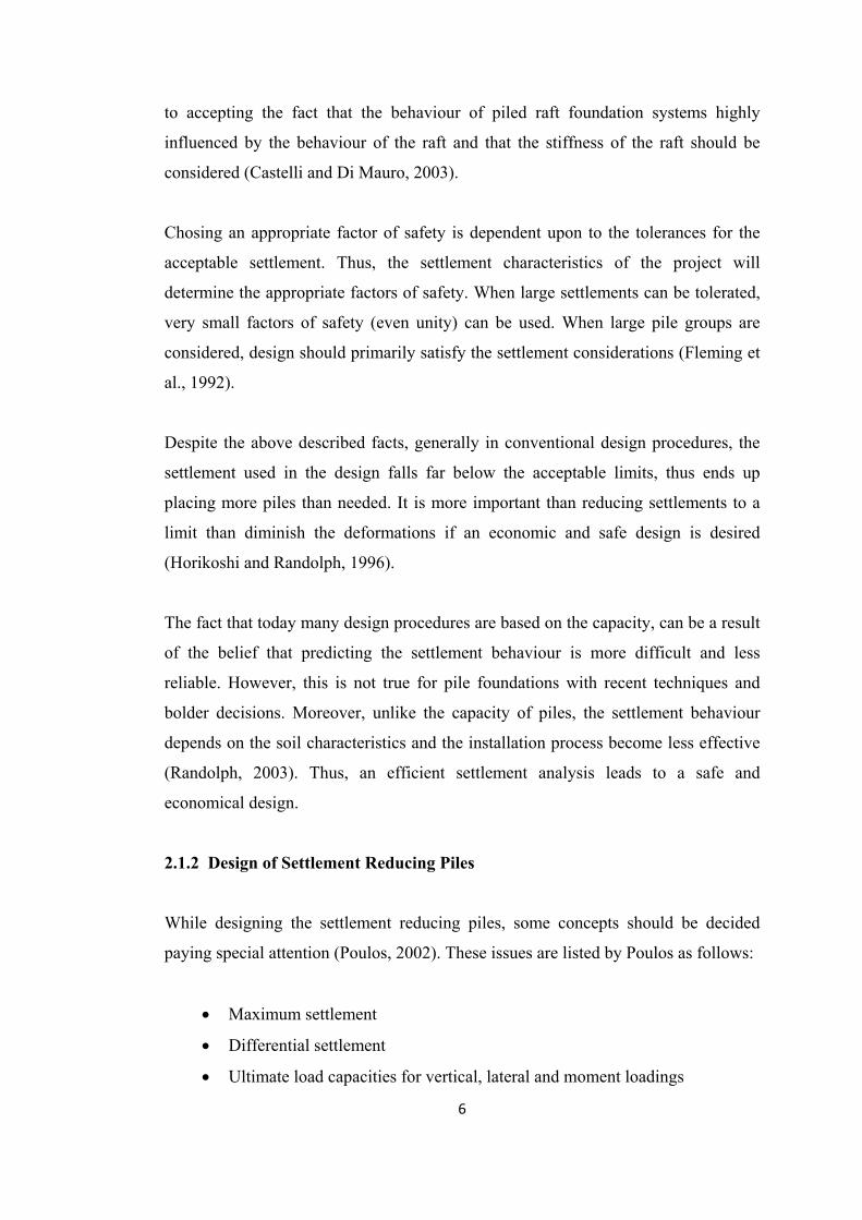
2.1.2 Design of Settlement Reducing Piles
While designing the settlement reducing piles, some concepts should be decided
paying special attention (Poulos, 2002). These issues are listed by Poulos as follows:
• Maximum settlement
• Differential settlement
• Ultimate load capacities for vertical, lateral and moment loadings

7
• Pile loads and moments
• Raft moments and shears
In the design process, for the settlement reducing piles special attention should be
given to avoid the overdesign, since it can cause as much trouble as designing
undercapacity (Love, 2003).
However, since piles are only there to reduce settlements, they do not contribute to
the bearing capacity. Hence, the unpiled raft should be sufficient from the bearing
capacity point of view and it should provide a factor of safety of at least 3 (De
Sanctis et al.,2002).
Unfortunately, engineers have been designing the systems based on the principle that
adequate number of piles should be placed in order to carry the structural weight.
However, they should be thinking in terms of settlements and the placement should
be done according to the acceptable settlement limits (De Sanctis et al.,2002).
While designing the settlement reducing piles, the load sharing between raft and piles
should be taken into account since the piles are not placed to provide bearing
capacity. However, the settlement behaviour of the raft directly changes when the
piles are presented so, this load sharing becomes more important. This load sharing is
based on the stiffnesses of the soil and raft and the pile settlements (Love, 2003).
The load sharing behaviour of the system highly depends on the working conditions
of the piles, i.e. the factor of safety values applied to the piles. There are some
detailed analysis of case histories in the literature which give reasonable explanations
about the relation between load sharing and the load carrying performances of the
piles and rafts. In the paper presented by O’Neill in 2005, some case histories were
investigated. It has been seen that when piles are loaded to 50 percent of their
ultimate capacities, the load carried by the raft drops to almost one-half of the total
load whereas when they are loaded to 80 percent or above of their ultimate
capacities, the piles carry a lower proportion of the load (O’Neill, 2005).
8
In order to optimize the design process of settlement reducing piles, some parameters
need to be decided like the mandatory pile number, the deficient load capacity of
each pile and the allowable settlement. At the mean time, the load sharing behaviour
and the relative settlement relationship should be analysed in detail (Fioravante et al.,
2008).
2.1.3 The Analytical Methods For Settlement Analysis of Settlement Reducing
Piles
The analytical methods for analysing the settlement reducing piles should be based
on the fact that no safety factors will be applied to the capacity of piles. Thus, they
will be used just for the settlement reducing and they will have very little or no
contribution to the bearing capacity. Accordingly, some of the conventional methods
will not be suitable for analysing the settlement reducing piles. In case of such
foundation systems, methods which consider the load sharing and provide
opportunity to mobilize full capacities of piles, should be used. The methods which
have been used and compared with the case histories are presented below.
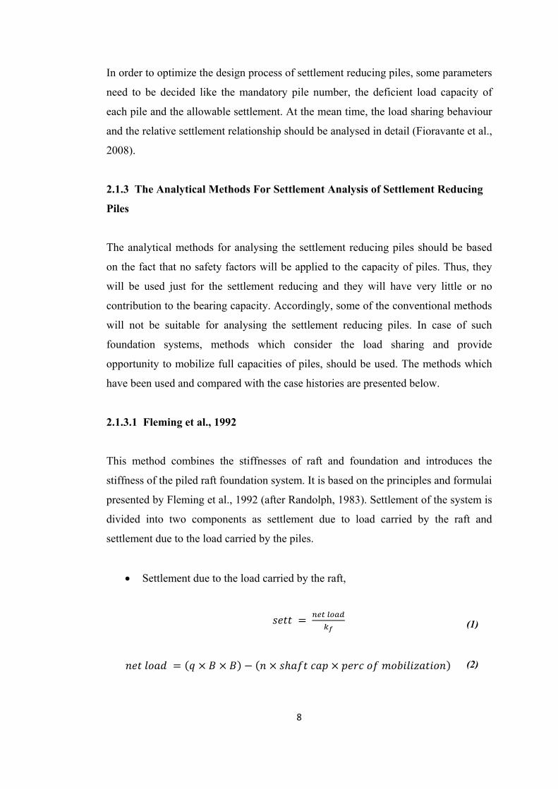
2.1.3.1 Fleming et al., 1992
This method combines the stiffnesses of raft and foundation and introduces the
stiffness of the piled raft foundation system. It is based on the principles and formulai
presented by Fleming et al., 1992 (after Randolph, 1983). Settlement of the system is
divided into two components as settlement due to load carried by the raft and
settlement due to the load carried by the piles.
• Settlement due to the load carried by the raft,
(1)
(2)

9
Where; ro = pile radius.
2.5 1
Where; B = width of the foundation,
n = number of piles in the group,
L = length of the piles,
ν = poissons ratio of the soil and
ρ = soil inhomogenity factor (ratio of GL/2 to GL)
GL/2 and GL are shear modulus at half length and full length of the pile respectively.
2
ln
21
Where; I = influence factor for the raft.
• Settlement due to the load carried by the piles,
. .
Where; Rs = settlement ratio.
(3)
(4)
(5)
(6)
(7)
(8)
(9)
(10)

10
• Thus, the total settlement will be sum of the two settlements calculated
above.
2.1.3.2 Clancy and Randolph, 1993
This method considers the interaction between pile and raft. Moreover, like the other
methods, the overall stiffness of the piled raft system is considered. Thus, settlement
is calculated as follows.
1
Where; n = number of piles and
d = diameter of pile.
21
Where; I = influence factor for the raft.
2.5 1
(11)
(12)
(13)
(14)
(15)
(16)
(17)

11
Where; L = length of the piles,
ν = poissons ratio of the soil and
ρ = ratio of GL/2 to GL
Furthermore, the values of αrp and αpr can be calculated again in order to check with
previously calculated values.
Where; Pr = load carried by the raft and
Pp = load carried by the piles.
2.1.3.3 De Sanctis et al., 2002
In the method presented, the system is classified in two groups as small and large
rafts. The small piled rafts are those systems in which the raft alone is not adequate
to fullfill the bearing capacity requirements. Also, the width of the raft is usually
between 5 to 15 meters and is small compared to the length of the piles. On the other
hand, the large piled raft foundations are those in which the piles are used only as
settlement reducers and in general in such systems, the width of the raft is larger
compared to the length of the piles.
Some curves have been presented in order to calculate the average settlement
reduction which is the ratio of settlement of the raft with piles to the settlement of the
unpiled raft. From these curves, it can be realized that the ratio is dependent upon
some factors. These factors are described herein.
• The relative structural stiffness of the raft; Krs,
K E υE υ B
(18)
(19)
(20)
12
Where; t = thickness of the raft,
B = width of the raft,
νs = poissons ratio of the soil,
νr = poissons ratio of the raft,
Er = modulus of elasticity of the raft and
Es = modulus of elasticity of the soil.
• The ratio of the pile group area to the raft area; Ag / A,
√ 1
Where; n = number of piles in the group and
s = spacing of the piles.
• The average settlement of the unpiled raft; (De Sanctis et al., 2002, after
Fraser and Wardle, 1976),
Where; q = load applied per metersquare and
Iw = influence coefficient.
• The ratio of the length of the piles to the width of the raft; L/B,
These parameters will be used to estimate the settlement reduction factor. For this
aim, some curves had been formed by De Sanctis et al.(2002). These curves for the
small and large piled rafts are given below in Figures 2.1 and 2.2 respectively.
(21)
(22)
(23)

13
Figure 2.1 Average settlement reduction for small piled rafts(De Sanctis et al. , 2002)

14
Figure 2.2 Average settlement reduction for large piled rafts (De Sanctis et al. , 2002)
2.1.4 Advantages of Settlement Reducing Piles
The concept of settlement reducing piles has some very useful benefits. For instance,
since the piles are introduced as settlement reducers, the required raft thickness, for
an acceptable vertical and differential settlement, is thinner. Moreover, this concept
relies on placing piles at necessary locations and in necessary numbers. These two

15
points results in a more economic design. (Love, 2003) However, this concept also
provides the required safety and the desired behaviour. In other words, this system
will give the opportunity to provide the most economic solution with satisfying the
necessary requirements for the desired behaviour (De Sanctis et al.,2002 after
Viggiani, 2000).
Figure 2.3 Typical pattern for performance vs. cost (De Sanctis et al. , 2002)
In Figure 2.3, it can be seen that for some situations when more money is being
spent, settlement decreases continuously while for other situations no matter how
much money is being spent, after a limit no benefit can be supplied. Moreover, it
should not be forgotten that there are acceptable limits for the settlement; thus it is
not necessary to diminish the settlement.
Another advantage of placing settlement reducing piles under the raft is from the
differential settlement point of view. This concept certainly minimizes the
differential settlement further in some situations, differential settlement diminishes
16
(De Sanctis et al.,2002). It should be noted that, while controlling the differential
settlement the location of piles becomes also important.
Furthermore, since this concept involves thinner rafts and less pile, the construction
time will be reduced and less workmanship will be needed.
On the other hand, it should be noted that the settlement reducing piles can also be
used to minimize the differential settlement and total settlement for flexible rafts as
well as the rigid rafts (Fioravante et al., 2008).
So, it can surely be concluded that, though it is a new concept, settlement reducing
piles have a large range of application fields and it is a very beneficial concept due to
the fact that it combines economy, safety and applicability.
2.2 Piled Raft Foundations
In foundation engineering, generally the most popular types of foundations used for
high rise buildings or special structures are raft foundations or pile foundations.
These systems when implemented alone, will fullfill the design requirements;
however, in most cases they become oversafe and economically not efficient. Further
more, in some cases when being used alone they can cause some important problems.
On the other hand, when the conditions are suitable, these systems can be combined
and one can have a more efficient, safe and economical design. Thus, piled raft
foundation system is one of those combined systems.
2.2.1 General Concepts About Piled Raft Foundations
As stated by Poulos (2001), the behaviour of a piled raft foundation is affected by
some factors like; the number of piles, the nature of loading, raft thickness and
applied load level. Some researches have been made on piled raft foundations giving
special attention to these effects.

17
When the number of piles is considered, it can be seen that increasing the number of
piles not always brings the best solution and best performance. Thus, with an
optimum number, the system will be more efficient. Increasing number beyond an
optimum number does not always generate a big difference (Poulos, 2001).
The design of a piled raft foundation has three main stages as preliminary stage,
detailed examination phase and detailed design phase (Poulos, 2001).
In a preliminary stage, usually the effects of pile number on load carrying capacity
and settlement is observed. In order to see these effects, the performance of a raft
foundation without piles needs to be analyzed. Using this analysis, it can be known if
the raft alone satisfies the ultimate load capacity or not. This stage helps us to decide
on the design philosophy.
In the detailed examination phase, the pile locations and some requirements are
decided. In order to locate the piles, the load distribution under the raft with no piles
underneath should be known. Generally, detailed analysis is not done for the load
distribution, but it is accepted as uniform over the raft area. However, for this step, a
detailed analysis needs to be done and the maximum loads under columns should be
found. Then it can be decided under which columns, a pile is needed. This is decided
by considering the exceedence of maximum moment, maximum shear in the raft or
the maximum contact pressure below the raft.
Finally, in the third stage, a detailed analysis and confirmation is done for the
location and number of piles, i.e optimum number and locations are decided. There
are several methods for analysing the pile raft systems as stated by Poulos, 2001.
These methods can be classified as follows:
1) “strip on springs” approach: Raft is modeled as a series of strip footings and
piles are modeled as springs.
2) “plate on springs” approach: Raft is modeled as plate and piles are modeled
as springs.

18
3) Boundary element methods: Both raft and piles are discretised and elastic
theory is used.
4) Combined methods: Uses boundary element analysis for piles and finite
element analysis for the raft.
5) Simplified finite element analysis
6) 3-D finite element analysis
2.2.2 Design of Piled Raft Foundations Based on Settlement Analysis
In order to understand the design methods and settlement analysis, the settlement
behaviour of pile groups should be analysed. There are some factors which affect the
settlement behaviour of piles in a group. These factors which are explained by
Poulos (1993) can be listed and described as follows:
1) Lateral non-homogenity of soil
This non-homogenity creates variation in soil stiffness and this variation is
especially important for bored piles. While assessing the settlement of piles, the
most important geotechnical parameter is the soil stiffness, i.e. the Young’s
modulus(Es) or the shear modulus(Gs). It should be noted that there can be
different values of Young’s modulus encountered in the pile shaft, just below the
pile tip, well below the pile tip and between the piles. There are some useful
correlations which can be used to calculate the modulus. Usually in those
emprical correlations, some standart in-situ tests are used, like the standart
penetration test or the cone penetration test. However, it is important to realise
that these relations only give an approximate value and should not be relied on
completely. Some of these correlations are developed by several researchers such
as Hirayama, Poulos and Wroth. There are several factors which influence the
soil stiffness, such as:
• Soil type
• Installation effects
• Stress level and system type
• Stress history

19
• Short-term and long-term conditions
• Initial stres level
2) Nonlinear pile response
Since the nonlinearity of the pile group response is severe than the nonlinearity
of the single pile response, the nonlinear effects increase the settlement ratio
which is the ratio of settlement of the piled raft to the settlement of unpiled raft.
As the load level increases, the group settlement ratio also increases.
3) Short-term and long-term settlements
In clay the short-term settlements are calculated using the undrained soil
modulus whereas, for long-term conditions drained modulus is used. There are
successfull empirical relationships which relate the drained modulus to the
undrained modulus. These formulations are acceptable but for normally
consolidated clays, it may estimate the undrained modulus lower than reality.
This leads to an underestimation of the consolidation settlement, thus the final
settlement appear lower than the actual conditions. The ratio of the short-term to
long-term settlement of a group is affected by the efficiency of piles in a group.
Thus, this efficiency decreases with the decrease in the Poisson’s ratio.
4) Shadowing effect in pile groups
This effect appears when the spacing is close, thus results in the overlapping of
the failure zones of the rows of piles in a group. This overlapping, i.e. the
shadowing effect will cause a reduction in lateral capacity and increase in the
group deflection. This fact leads to setting some limitations for pile spacing.
Since the design will be based on the settlement analysis, the behaviour should be
analysed very carefully.
Though the piles are generally used to reduce settlement, conventionally design
process is based on the axial capacities. In the design, settlement analysis should be
done properly with paying attention to the causes of the occured settlement, i.e. if the
settlement is caused by external loads on piles or caused by things other than loads.

20
Moreover, the settlement analysis should take into account some important factors
like load distribution in the pile, length of the zone above and below the neutral
plane, drag load at the location of the neutral plane, pile shaft and toe resistance at
long term equilibrium, etc.
The settlement based design should include a proper settlement analysis. There are
numerous techniques which calculate the settlement of piled-raft foundations. They
can be classified due to the models they use and due to the acceptances made while
analysing. According to Poulos(1993), the analysis methods can be classified as
follows:
1) Purely empirical techniques that relate settlement to that of a single pile
2) Simplified techniques that reduce the pile group system to an equivalent raft
3) Analytical methods that consider interaction between piles and the
surrounding soil
Methods in the first category can be described briefly as; the methods in which
interaction factors are used by superpositioning, the ones in which the load
settlement curves are modified to cover the group effects and the settlement ratio
methods. Interaction factors are ratios derived in order to relate settlement of single
pile to that of a group of piles.
The second category methods are those in which the system is considered not
seperately but as a whole group. They can sometimes be suitable for settlement
calculation; however they are not suitable for determining the settlement distribution
(Poulos, 2006). The equivalent raft method, the equivalent pier method and different
versions of these methods can be considered as such. Furthermore, it should be noted
that the traditional approaches based on the equivalent raft systems are currently
replacing by the techniques which consider the interactions between piles, thus
giving proper attention to the number of piles in a group (Fleming et al., 1992). The
methods lay in the first and the third categories can be considered as such. Besides,
the second category of the methods will not be in the scope of this research, since
they have no contribution to the pile number-settlement relationship.
21
The importance of the third category comes from the fact that the pile-pile, pile-raft,
raft-pile and raft-raft interactions are very important in the design and analysis of the
piled raft foundation systems. Thus, if these effects are ignored, both the capacity
evaluation and settlement prediction will be highly misleading.
Unfortunately, in practice, the analytical approaches used in the settlement analysis
for the design process usually accept the piled raft system as an equivalent raft and
do not consider the number of piles in the group. This tendency is generally due to
the generalization that as the pile number increase, maximum settlement decreases.
This is of course true, but this is true for some extend. Ideally and more logically
there should be an optimum number of piles which beyond this value, no
considerable reduction in settlement will occur. Thus by considering the settlement
analysis methods which takes into account the number of piles, a more economical
but still safe design could be possible.
2.2.3 The Analytical Methods For Settlement Analysis of Piled Raft
Foundations
In this research, the methods considering the number of piles in the group will be
analysed in order to correlate the number of piles with the settlement and to verify
that there is an optimum number for piled raft systems. The known methods in the
literature will be briefly discussed further in this section.
2.2.3.1 Methods Considering Interaction Factors
In the methods which consider the interaction factors to evaluate the group
settlement, the main issue is about determining the interaction factors. Thus, the
differences in the techniques come from the difference in obtaining the interaction
factors.
There are several factors which the interaction factor depend upon. These factors,
combined from the works of two previous researchers; Lee, 1993 and Poulos, 1993,
are presented below:

22
i) Spacing between piles
ii) Length to diameter ratio of piles
iii) Stiffness of piles relative to soil
Regarding to above three factors, the effects are analysed by Lee (1993) and the
results are discussed below.
Effects of pile spacing and stiffness of piles relative to soil (λ) is shown in
Figures 2.4 and 2.5 for homogeneous soil and nonhomogeneous soil (Gibson
soil) respectively for different length to pile radius ratios. These figures are
prepared
Figure 2.4 Effects of pile spacing and stiffness relative to soil for homogeneous soil
(Lee, 1993)
23
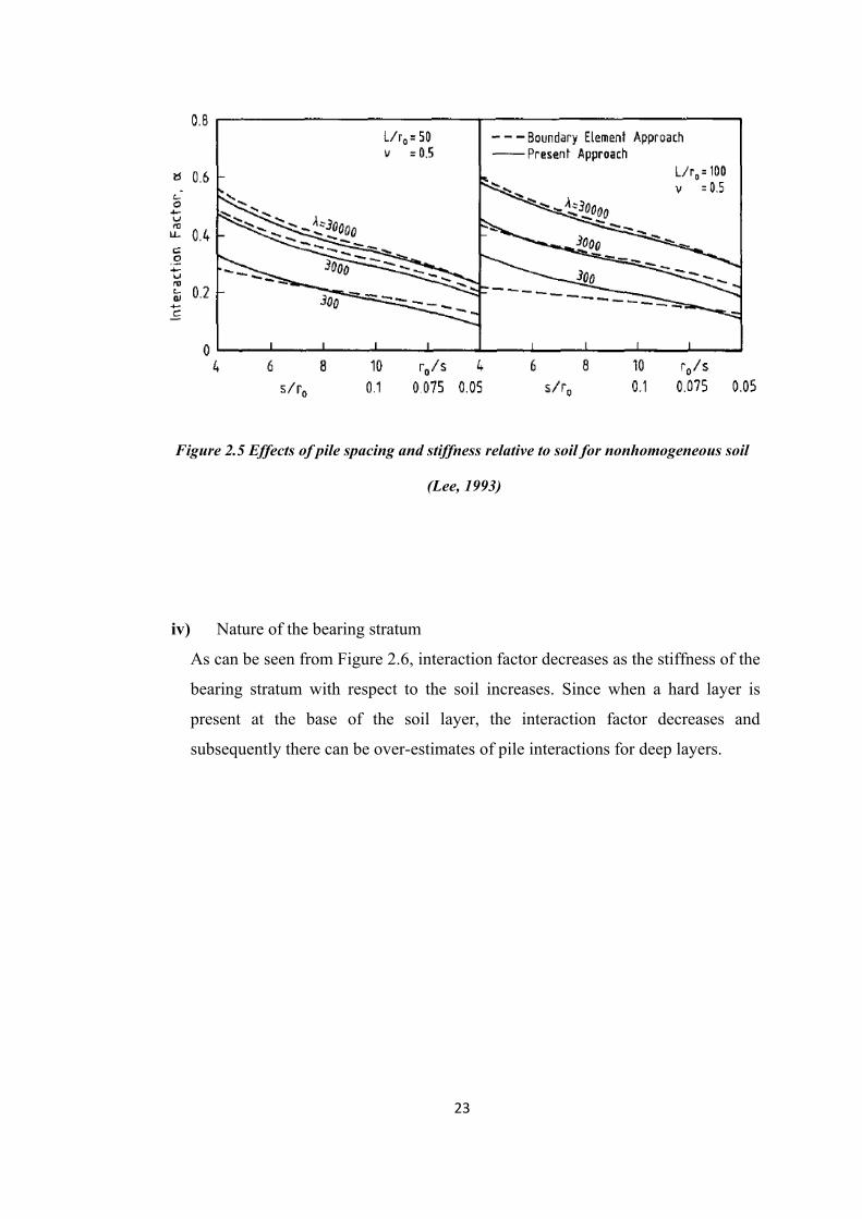
Figure 2.5 Effects of pile spacing and stiffness relative to soil for nonhomogeneous soil
(Lee, 1993)
iv) Nature of the bearing stratum
As can be seen from Figure 2.6, interaction factor decreases as the stiffness of the
bearing stratum with respect to the soil increases. Since when a hard layer is
present at the base of the soil layer, the interaction factor decreases and
subsequently there can be over-estimates of pile interactions for deep layers.

24
Figure 2.6 Influence of bearing stratum stiffness on interaction factors (Poulos, 2006)
v) Distribution of soil modulus with depth
As can be seen from Figure 2.7, in non-homogeneous soils the interaction factors
are smaller than that of the uniform soil profiles. So, if the non-homogenity of the
soil is not considered, the settlements will be over-estimated.
There are several methods to overcome the problem of the layered soil profiles,
like Mindlin’s equation and the other modified methods. The methods differ due
to whether or not the soil gets stiffer with depth or gets softer with depth.

Figure 2
vi) Ty
vii) Sti
Betwe
piles t
factor
viii) Eff
As di
differe
If the p
If the piles
2.7 Influence
ype of loadin
iffer soil bet
een the piles
than at the
reduces sig
ffects of sim
isplayed by
ence in diam
piles i and j
s i and j hav
e of soil mod
ng
tween the p
s there exist
pile-soil int
gnificantly.
milar and dis
y Hewitt (
meter or leng
have differ
ve different
25
dulus distribu
piles
t small strai
terface. Thu
ssimilar pile
(1988), int
gth of the p
rent lengths
diameters,
5
ution on inte
in levels wh
us, due to t
es
eraction fa
piles present
s, then;
then;
eraction fact
hich lead a
this stiffer s
actors are
t.
tors (Poulos,
stiffer soil
soil, the int
effected fr
, 2006)
between
teraction
rom the
(24)
(25)

26
ix) Compressible underlaying layers
Although the compressible layers below the pile tips do not affect the settlement
of a single pile, in a pile group this presence increases the settlement. This effect
is especially important for the larger groups. If this effect is not taken into
account, the calculated settlements will be much greater than that of having a
continuous competent stratum.
x) The effect of applying the interaction factor on both the elastic and plastic
component
It has been argued by several researchers that the interaction factor should only
be applied to the elastic component, since plastic component does not transmit to
the adjacent piles.
Also from Figure 2.8, the difference arises from applying the interaction factor
only to elastic component can be seen. It is clear that if the interaction factor is
applied to the total settlement, the settlement will be greater, thus over-estimated.
Figure 2.8 Effect of basis of analysis on group-load settlement behavior (Poulos, 2006)
The origi
factor, α v
are genera
the bound
solutions
Some solu
methods w
i) M
ii) Le
iii) M
iv) Ca
Bu
In this me
where, K =
f = efficien
n = numbe
k = individ
The efficie
where, e =
As stated b
• Le
• λ,
• Sp
• Sl
• Po
nal approa
versus ratio
ally taken f
dary elemen
are availab
utions deve
will be expla
Mandolini an
ee, 1993
Modified calc
alculation o
utterfield an
thod, the sti
= the group
ncy
er of piles in
dual pile sti
ency can be
= the expone
by Fleming
ength to dia
pile stiffne
pacing of th
lope of the s
oisson’ s rat
ches accep
of pile spa
from a com
nt analysis.
le to calcul
eloped by d
ained in det
nd Viggiani,
culation of i
of a pile gr
nd Douglas(
iffness of th
p stiffness
n a group
iffness
e calculated
ent which c
g et al., 1992
ameter ratio
ss ratio (Ep
he pile
stiffness inc
tio 27
pt interactio
acing to dia
mplete analy
However,
late the val
different res
tail.
, 1997
interaction b
roup settlem
(1981)
he pile grou
d using equa
can be obtain
2; the expon
of the pile
/ Gs )
crease with
7
on factors
ameter of pi
ysis of two
today also
lues of the
searchers w
by Poulos,
ment based
up can simpl
ation 27.
ned by som
nent,e is dep
depth
from the p
ile, s/d. The
equally loa
some clos
interaction
will be given
1988
d on the m
ly be evalua
me charts (Ap
pended upon
plots of int
ese graphic
aded piles,
sed form, e
factors in
n below; al
method prop
ated as follo
ppendix A)
n some fact
teraction
al forms
likewise
empirical
a group.
so some
posed by
ows.
tors like;
(26)
(27)

The settlem
where, S =
P = averag
The case h
the group
2.2.3.2 M
Interaction
settlement
settlement
addressed
1988). Set
this ratio.
where, SG
RS
S1a
The settle
interaction
approxima
the group,
ment of a gr
= the group
ge load per
histories sh
settlement i
Methods Co
n factors ca
t, settlemen
t of the pile
using a fle
ttlement of
= group se
= settlemen
av = single p
ement ratio
n factor to
ated by som
, for exampl
roup can be
settlement
pile
how that thi
if the soil p
nsidering S
an also be
nt ratio met
es will be m
exibility rat
f a group ca
ttlement
nt ratio
pile settleme
can be eva
calculate
me analytic
le the one R
28
e determined
s simple ca
arameters a
Settlement
used in an
hod. In a g
more than th
tio, which i
an be relate
ent under sa
aluated by s
the settlem
al formulat
Randolph pr
8
d using the
alculation is
are determin
Ratio
nother meth
group, unde
hat of a sin
is known as
ed to the set
ame average
several mea
ment ratio.
tions, consi
roposed (Po
group stiffn
s reasonable
ned accurate
hod for est
er a known
ngle pile. Th
s the settlem
ttlement of
e load
ans. One of
Also settle
idering the
oulos,1993).
ness.
e while dete
ely.
timating pil
load for ea
his incraese
ment ratio
f a single pi
f them is u
ement ratio
number of
.
(
ermining
le group
ach pile,
e will be
(Mohan,
ile using
using the
can be
f piles in
(28)
(29)
(30)

where, n =
w = expon
It should
componen
Thus, usin
Stiffness o
number an
where, n =
k = single
ηw = an ef
This effic
calculated
in the asse
2.2.3.3 M
The linear
deformatio
transfer cu
linear ana
represent
that point.
to use in t
as follows
i) Th
pa
= number of
nent (genera
also be not
nt of the sing
ng this settl
of the pile
nd an efficie
= number of
pile stiffne
fficiency fac
ciency will
d using some
essment of t
Methods Co
r models us
on characte
urves can b
alysis. In t
the relation
. However,
the group an
s as stated in
he value of
arameters lik
f piles in the
ally lies betw
ted that, se
gle pile sett
lement ratio
group is a
ency param
f piles in a g
ess
ctor (for no
either be
e empirical
the overall s
nsidering L
sed in the de
eristics of s
e used inste
this categor
nship betwe
this metho
nalysis, sin
n Basile (20
f the modul
ke soil prop
29
e group
ween 0.2 –
ettlement ra
tlement.
o, the stiffn
function o
eter.
group
interaction,
accepted a
correlation
settlement o
Load Trans
esign of pil
soil. In orde
ead. These
ry of meth
een the load
d should al
nce it has lim
003);
lus of the s
perties, pile
9
0.6 )
atio should
ness of the
of the stiffn
, taken as un
as the inver
ns. This grou
of the pile g
sfer Curves
e groups do
er to overc
methods gi
hods load-tr
d at any poi
lso be modi
mited use. T
subgrade re
e properties
only be ap
pile group
nesses of in
nity)
rse of the
up stiffness
group.
s
o not consid
ome this b
ve the oppo
ransfer fun
int and the
ified in ord
These limita
eaction will
and loadin
pplied to th
p can be ca
ndividual pi
settlement
can further
der non-line
ehaviour, th
ortunity to r
nctions are
soil deform
er to be con
ations can b
depend on
ng condition
e elastic
lculated.
iles, pile
ratio or
r be used
ear load-
he load-
run non-
used to
mation at
nvenient
be stated
n several
ns. Since
(31)

no
ju
ii) Fr
pi
ev
cu
iii) Th
Regarding
analysis o
modificati
the pile gr
1) Sh
This appro
provides a
The deform
for i = 1, 2
where, βij
z = depth b
l = pile len
where, [h]
o direct te
dgement is
rom the ana
le can be ga
valuating th
urves for sin
he effect of
g these lim
of pile gr
ions this me
roups.
hen et al., 20
oach consis
a quick estim
mation alon
2, …….., np
= undeterm
below the p
ngth
] = coefficie
ests can g
required. T
alysis, no in
athered. Thu
he group eff
ngle piles.
pile-head fi
mitations, it
roups, som
ethod can o
000
sts of simpl
mation of se
ng the shaft
p
mined coeffi
pile head
ent matrix fo
30
give force-
This leads to
nformation
us, the inter
fects is only
fixity to the
is clear th
me modifica
only be used
le formulai
ettlement of
can be eval
cients
for pile-soil
0
displaceme
o some error
about the d
raction betw
y possible b
results is no
hat, in orde
ations shou
d to design
based on t
f symetrical
luated as fo
system
nt relation
rs.
deformation
ween piles c
by modifyin
ot clear.
er to use th
uld be don
the similar
the load-tra
l and rectang
llows:
nships, eng
n pattern aro
cannot be fo
ng the load
hese curve
ne. Withou
r piles not to
ansfer curve
gular pile g
gineering
ound the
ound. So,
-transfer
s in the
ut these
o design
es which
groups.
(32)
(33)
(34)

[kp], [ks],
{PT} = vec
Inverse of
The stiffne
For single
where, Ep
ro =
where, Gt
where, ρ =
that of the
[A] and [ksb
ctor related
f matrix [h]
ess relation
e piles:
= pile modu
= radius of t
= shear soi
= soil inhom
e base)
b] = matrice
d to the load
gives the fl
ship is as fo
ulus
the pile
l modulus a
mogenity fa
31
es related to
s at pile hea
lexibility rel
ollows:
at pile toe
actor (ratio
1
o the stiffnes
ads.
lationship o
of shear so
ss of piles a
of the piles.
il modulus
and soil
at pile midddepth to
(35)
(36)
(37)
(38)
(39)
(40)
(41)

νs = Poisso
Thus, [h] c
where, λ =
on’s ratio
can be evalu
= relative sti
uated as fol
iffness of pi
32
llows:
iles
2
(47)
(46)
(45)
(44)
(43)
(42)
(48)
(49)

The pile lo
For symet
The load s
If there are
oad settleme
tric pile grou
settlement r
e three sym
ent ratio can
ups:
ratio for two
metric piles:
33
n be given a
o piles can b
3
as;
be determin
ed as descri
ibed below.
(
(
(
(
(
(5
.
(52)
(51)
(50)
(53)
(54)
(55)
(56)
57)

If there are
Moreover
elastic hal
In the belo
of piles fo
determine
is determin
e four syme
, the above
lf space with
ow figures,
or different
d under a “
ned under a
etric piles:
e described
h the settlem
the inverse
radii, spac
“s/d” ratio o
a “s/d” ratio
34
procedure c
ment ratios.
e of the sett
ing to radiu
of 6 and a P
o of 10 and a
4
can be used
lement ratio
us ratio and
oisson’s rat
a Poisson’s
d to analyse
o is plotted
d Poisson’s
tio of 0.5, w
ratio of 0.2
e the pile g
against the
ratio. Figu
whereas Fig
2.
(5
(6
(59
groups in
e number
re 2.9 is
gure 2.10
58)
60)
9)

35
Figure 2.9 Graph of 1/Rsr versus number of piles for s/ro=6, νs=0.5 (Shen et al, 2000)

Figure 2
It can clea
line. Thus
easily be
curves, th
equation.
2.10 Graph of
arly be seen
s, by determ
obtained.
he Equation
of 1/Rsr versu
n that the ab
mining the e
From the
ns 52 and
36
us number of
bove relatio
equation of
above desc
53 for sing
6
f piles for s/r
onship of th
f this line, th
cribed proc
gle piles ca
ro=10, νs=0.2
he settlemen
he behaviou
cedure usin
an be used
2 (Shen et al
nt ratio is a
ur of the gr
ng the load
d to determ
l, 2000)
a straight
roup can
-transfer
mine this
(61)
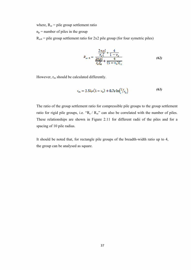
where, Rsr
np = numb
Rsr4 = pile
However,
The ratio o
ratio for r
These rela
spacing of
It should b
the group
r = pile grou
ber of piles i
e group settl
rm should b
of the group
rigid pile gr
ationships a
f 10 pile rad
be noted th
can be anal
up settlemen
in the group
lement ratio
be calculate
p settlemen
roups, i.e. “
are shown
dius.
hat, for recta
lysed as squ
37
nt ratio
p
o for 2x2 pil
d differently
nt ratio for c
“Rs / Rsr” ca
in Figure
angle pile g
uare.
7
le group (fo
y.
compressibl
an also be c
2.11 for di
groups of th
or four syme
e pile group
correlated w
ifferent rad
he breadth-w
etric piles)
ps to the gro
with the nu
dii of the pi
width ratio
oup settlem
umber of pil
iles and fo
up to 4,
(62)
(63)
ment
les.
or a

38
Figure 2.11 Normalized group settlement ratio versus number of piles (Shen et al, 2000)

2) A
This meth
curves usi
the previo
since it do
gives reas
briefly.
In a group
for i = 1,2
where, βij
z = depth b
l = pile len
where, [h]
[kp], [ks],
{PT} = vec
By expres
submatrice
modified m
hod is an app
ing a simpl
ous explaine
oes not use
sonable resu
p of piles, th
,….,np
= undeterm
below the p
ngth
] = coefficie
[A] and [ksb
ctor related
ssing the m
es and maki
method pre
proach to ca
le spreadsh
ed method
complex co
ults. Below,
he displacem
mined coeffi
pile head
ent matrix fo
b] = matrice
d to the load
matrices re
ing some ad
39
sented by S
alculate the
eet calculat
by Shen et
omputer pro
, the theory
ment of a pil
cients
for pile-soil
es related to
s at pile hea
lated to th
djustments,
9
Shen and T
group stiffn
tion. The ca
t al., 2000.
ograms, it is
y beneath th
le “i” can b
system
o the stiffnes
ads.
he stiffness
the Equatio
Teh, 2002
fness based
alculations
This meth
s not very ti
his approach
e given as:
ss of piles a
of piles a
on 65 can be
on the load
are very si
od is advan
ime consum
h will be ex
and soil
and soil wi
e written as
-transfer
imilar to
ntageous
ming and
xplained
ith their
s:
(64)
(65)
(66)
(67)

The matric
If the pile
follows:
where, P =
Equation 6
For the va
and Wroth
ces [ksij], [k
s in the gro
= overall ve
69 can also
alue of ζ, d
h, 1978 and
ksbij] and [Bs
oup assumed
ertical load a
be written a
determinatio
Fleming et
40
s] are given
d to be settl
applied on t
as:
on can be d
t al, 1992) :
0
in Appendi
led equally,
the pile cap
done using t
ix B.
the equatio
.
the below e
on can be w
equation (R
written as
Randolph
(68)
(69)
(71)
(70)
(72)
(73)
(74)
(75)
(76)
where,
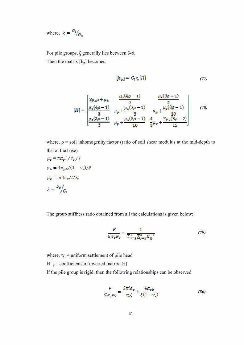
For pile gr
Then the m
where, ρ =
that at the
The group
where, wt
H-1ij = coe
If the pile
roups, ζ gen
matrix [hp] b
= soil inhom
base)
p stiffness ra
= uniform s
efficients of
group is rig
nerally lies b
becomes;
mogenity fa
atio obtaine
settlement o
f inverted m
gid, then the
41
between 3-6
actor (ratio
ed from all t
of pile head
atrix [H].
e following
1
6.
of soil shea
the calculati
d
relationship
ar modulus
ions is given
ps can be ob
at the mid-
n below:
bserved.
(
(
-depth to
(77)
(78)
(79)
(80)

The f-1sij an
[fsb]-1. The
the Appen
Another w
different v
nd f-1sbij in t
ese matrices
ndix C.
way of dete
values of sp
the above e
s are the inv
ermining the
acing to dia
42
equations ar
verses of the
e factors αp
ameter ratio
2
re the coeffi
e matrices [
p and αpb is
os. These ch
icients of th
[fs] and [fsb]
using the
harts are giv
he matrices
] which are
charts avail
ven in Figure
(
(
[fs]-1 and
given in
lable for
e 2.12.
(82)
(81)

43
Figure 2.12 Coefficients αp and αbp versus number of piles (Shen and Teh, 2002)

44
2.2.3.4 Methods Based on Complete Analysis
Complete analysis generally means to consider each pile in the group in detail.
Boundary element analysis, finite element analysis or some combined methods can
be used for this kind of analysis. This kind of methods can be used to overcome the
problems encountered in the load-transfer curve approaches and the interaction factor
method. By this complete analysis, the piles having different length, diameter,
stiffness or base and shaft resistance can be taken into consideration in detail. Also
nonlinear soil-pile response and the pile interaction can be considered. Moreover, the
load and bending moment distribution along the piles can easily be obtained.
Although this type of analysis is more accurate and more detailed, it is very time
consuming.
1) Finite element method
The finite element analysis determines the load transfer behaviour of the piles
through the surrounding soil however it is not very applicable to pile groups.
Moreover, this kind of analysis is very time consuming, the cost is very high and data
preparation needs too much attention. So, the boundary element analyse are more
preferable. However, recently with computer programs finite element analysis could
be done in a simpler manner. Of course while using these kind of programs, the
engineers should dominate to the rules and the acceptances of the program. Hence,
he or she should always be in control and do not rely on the program completely.
2) Boundary element method
Unlike the finite element analysis, the boundary element analysis gives accurate
solutions for pile groups, it is not very time consuming and it has a lower cost since it
gives solutions using the boundary values. It gives special care to some critical
locations like pile-soil interface.

45
There are several computer programs which uses the boundary element analysis with
several other methods have been developed by several researches. These are listed by
Fleming et al (1992). Some examples are given below:
DEPIG which is developed by Poulos in 1990. Uses a simplified boundary
element method analysis and interaction factors.
MPILE, originally named PIGLET (developed by Randolph, 1980). Uses a
semi-emprical method with analytical solutions and interaction factors.
PGROUP which is developed by Banerjee and Driscoll in 1976. Uses a
linear elastic analysis.
GEPAN which is developed by Xu and Poulos in 2000. Uses a linear
analysis.
PGROUPN which is developed by Basile in 1999. Uses a non-linear
boundary element analysis.
2.2.4 Advantages of Piled Raft Foundations
In many cases, especially when the raft alone does not satisfy the settlement and
differential settlement criteria but have an adequate load carrying capacity, using a
piled raft foundation instead of a conventional piled foundation, has many
advantages. Although, the conventional approaches are easier to deal with, when
applicable pile rafts, give a more convenient and economic solution. Moreover, these
systems are more successful at soil profiles consisting relatively stiff clays or
relatively dense sands and structures which has a high slenderness ratio.
Advantages of using a piled raft foundation can be listed as given by El-Mossallamy
(2002) :
• Heave will be minimised
• The required limits for differential settlements, settlements and tilting will be
satisfied
• If some regions of the foundation is subjected to different loads, this system
will minimize the differential settlement

46
• If eccentric loading or difficult subsoil conditions arise a risk of foundation
tilting, piled raft foundation system will decrease this tilting
• Since the new design requires placing piles at strategical locations, the raft
stresses and moments will be reducted.

47
CHAPTER 3
EXPERIMENTAL AND ANALYTICAL STUDIES ON SETTLEMENT
REDUCING PILES
3.1 The Experimental Studies on Settlement Reducing Piles
3.1.1 Scope of The Experimental Study
In this research, in order to support the analytical studies, a laboratory study is to be
conducted on model systems. The laboratory study will give an approximation about
the settlement behavior of pile groups with increasing number of piles.
In this study, it is intended to show that, increasing the number of piles do not cause
an excessive reduction in total settlement. Regardance of the conventional design
procedures, by increasing the number of piles, the optimization in the design could
not be satisfied. Thus, beyond an optimum number, settlement behavior will tend to
become steady. Expressed in a different way; although, adding piles to the raft solves
the settlement problem, the reduction in the amount of settlement does not continue
steadily; thus, reduction stops at an optimum number of piles. The experiments are
intended to show this behavior of settlement reducing piles, accordingly in the
experiments, the number of piles is augmented whereas all the other parameters like
pile length, pile diameter, type of soil, size of raft will remain constant.
In the experiments, the raft will be modeled with aluminum footings whose
dimensions are 50 x 50 x 10 mm and the piles will be modeled with brass nails with
rasped sides which are 2 mm in diameter and 75 mm in length. In the series of tests,
the model footings with different number of brass nails inserted beneath will be
subjected to the sustained loading and settlements will be measured. Because of the

48
dimensions of the model footing and the related limitations, at most 49 brass nails
can be inserted in a 7x7 square pattern.
Another important point that should be addressed is that, the given load is high,
resulting in the failure of the piles. In other words, in the designed model, under the
given load, the piles had been yielded and the capacity of piles is fully mobilized. So,
the model can be said to represent a system which is constituted of a raft with
settlement reducing piles.
3.1.2 Experimental Setup
In the experimental studies, the soil sample is prepared and consolidated under a
certain pressure. Then the model system is prepared and it is loaded to a decided
pressure. The settlements occurring under that pressure is measured using special
equipments.
In such a procedure, the elements constitute the model can be listed as follows:
• Plexiglas box
• Geotextiles
• Commercial type of kaolin clay
• Brass nails
• Aluminum footing
The necessary equipments to build up the setup and proceed the experiments can be
itemized as follows:
• Loading jack for consolidation process
• Timber templates for insertion of nails
• Load hangers
• Displacement dials
• Data acquisition system consists of a software that record readings, a data
logger and a computer

49
The above given entries will further be explained in this section.
3.1.2.1 Plexiglas Boxes and Geotextiles
In order to place the kaolin clay, the boxes manufactured by Kul (2003) was used.
The plexiglas box has inside diameters of 20 x 20 x 20 cm, the wall thickness is 1
cm. Before placing the kaolin clay, the geotextiles, which are used for drainage
purposes and to prevent drying of soil, were laid. The plexiglas box and the
geotextiles can be seen in below Figures 3.1 and 3.2.
Figure 3.1 Plexiglas box and geotextiles

50
Figure 3.2 Plexiglas box covered with geotextiles
It should be noted that the dimensions of the plexiglas boxes are well integrated with
the vertical stress distribution since the width of the model footing will be 5 cm and
the effective pressures distribution is extended down to 2 or 3 times width, i.e. 10-15
cm. Thus, the model can be said to be an elastic half space.
3.1.2.2 Commercial Type of Kaolin Clay
In the tests remolded kaolin is being used. Remolded kaolin has lower liquid limit
and lower activity, thus it is favored in most cases to the other types of clay. These
properties which provide avoidance from swelling, shrinkage and some other
problems enable kaolin type of clay as a preferable material for model studies. In
order to perform the study consciously, the sample is tested in the laboratory for
some typical material properties. The laboratory study and their results will further
be explained in the Section 3.1.3.1.

51
It should also be noted that the kaolin type of clay used for the experiments had been
derived from remolding of the kaolin powder, respecting the desired water content.
In the following experimental study, the water content is desired to be 40%. After
remolding process, the specimens are allowed to rest in the humidity room for at
least five or six days.
3.1.2.3 Brass Nails and Aluminium Footing
For modeling the raft with settlement reducing piles, brass and aluminum is used.
The schematic representation for a sample case with 16 piles is shown in Figure 3.3.
Figure 3.3 Schematic representation of the simple case
The piles are modeled with brass nails, 2 mm in diameter and 75 mm in length. It
should also be mentioned here that, the length of the nails are consistent with the
recommendations, i.e. nail length is 1,5 times the width of the footing. The nails have
rasped edges to enhance friction. In further analysis, the modulus of elasticity of
50x50x10 mm aluminum
Brass nails; 2 mm in diameter
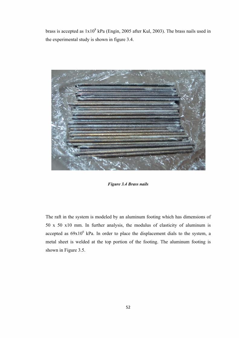
52
brass is accepted as 1x10⁸ kPa (Engin, 2005 after Kul, 2003). The brass nails used in
the experimental study is shown in figure 3.4.
Figure 3.4 Brass nails
The raft in the system is modeled by an aluminum footing which has dimensions of
50 x 50 x10 mm. In further analysis, the modulus of elasticity of aluminum is
accepted as 69x106 kPa. In order to place the displacement dials to the system, a
metal sheet is welded at the top portion of the footing. The aluminum footing is
shown in Figure 3.5.
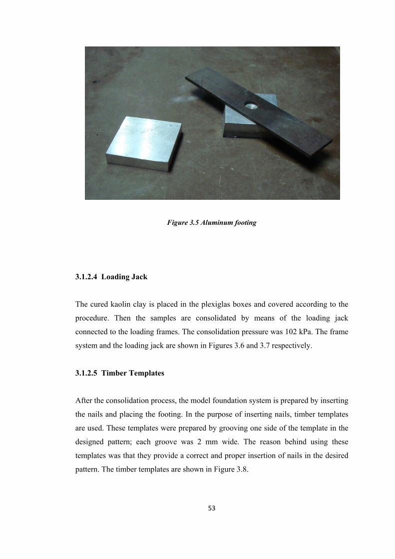
53
Figure 3.5 Aluminum footing
3.1.2.4 Loading Jack
The cured kaolin clay is placed in the plexiglas boxes and covered according to the
procedure. Then the samples are consolidated by means of the loading jack
connected to the loading frames. The consolidation pressure was 102 kPa. The frame
system and the loading jack are shown in Figures 3.6 and 3.7 respectively.
3.1.2.5 Timber Templates
After the consolidation process, the model foundation system is prepared by inserting
the nails and placing the footing. In the purpose of inserting nails, timber templates
are used. These templates were prepared by grooving one side of the template in the
designed pattern; each groove was 2 mm wide. The reason behind using these
templates was that they provide a correct and proper insertion of nails in the desired
pattern. The timber templates are shown in Figure 3.8.

54
Figure 3.6 Frame system
Figure 3.7 Loading jack

55
Figure 3.8 Timber templates
3.1.2.6 Load Hangers and Displacement Dials
When the preparation of the soil model is completed, the system was suspended to
the pressures of 75 and 40 kPa and the displacements have been measured. An
apparatus was prepared to maintain the desired circumstance. Constituents of the
apparatus are shown in Figure 3.9.

56
Figure 3.9 Constituents of the apparatus
The displacements have been measured by linear variable differential transformers
(herein after referred as lvdt). Lvdt is an electrical transformer used to measure linear
displacements. The lvdt’s used had been calibrated prior to the experimental study.
A schematic representation of the system is given in Figure 3.10.
3.1.2.7 Data Acquisition System
In order to deal with the readings taken from the lvdt’s, a data acquisition system was
used. This system included a 16-channel data logger (ADU), a computer and
software (DADU) that arrange and record the readings. The system is shown in
Figure 3.11.

57
Figure 3.10 Schematic representation of the system (Engin, 2005 after Kul, 2003)
Figure 3.11 Data acquisition system

58
3.1.3 Laboratory Testing
3.1.3.1 Laboratory Testing to Determine The Properties of Kaolin Clay
The properties of the kaolin type of clay had been determined with some standard
laboratory tests. Moreover, for each sample box some experiments were conducted
before and after the loading, to ensure that the boxes prepared were consisted with
each other. These experiments will further be explained in this chapter. Thus, it
should be noted that while performing each experiment, TS 1900 was taken as a
basis.
1) Specific Gravity Test
The specific gravity of the sample had been determined by the specific gravity
test, in which sample was crashed into small parts, dried for one day; then
smashed and mixed with distilled water. The result of the test is given in Table
3.1.
2) Atterberg Limits Tests
The liquid limit, plastic limit and the plasticity index of the sample had been
determined using Atterberg limit tests. The sample had been rested for a
sufficient time, thus became homogeneous and mature. Then sample was being
tested. The results are given in Table 3.1. Thus, according to the USCS (Unified
Soil Classification System), soil is classified as CL, i.e. low plasticity clay.
3) Hydrometer Analysis
The grain size distribution of the sample had been determined with the
hydrometer analysis since it was a fine grained soil. The test was conducted
with a dried, sieved and smashed sample. The grain size distribution graph is

59
given in Figure 3.12. Thus, according to the USCS (Unified Soil Classification
System), soil is classified as CL, i.e. low plasticity clay.
Figure 3.12 Grain size distribution graph
4) Consolidation Test
The compression index, coefficient of volume compressibility and coefficient of
vertical consolidation have been determined using the consolidation test. The
sample was consolidated with the consolidation apparatus under different
pressures. The results are shown in Table 3.1.

60
Table 3.1 Results of the standart laboratory tests on kaolin clay
NAME OF THE
EXPERIMENT RESULTS OF THE EXPERIMENT
Specific gravity test Gs = 2.60
Atterberg limits LL = 42.5 % , PL = 24 % , Ip = 18.5 %
Consolidation test
cc = 0.70
mv values are given in table 3.2, e versus log σ graph
and
cv versus σ graph are given in figures 3.13 and 3.14,
respectively.
Table 3.2 mv values obtained in consolidation test
Consolidation
pressure (kPa) mv (m2/kN)
0-50 0.0004571
50-100 0.0003468
100-200 0.0002353
200-400 0.0001205
400-800 0.0001080
800-1600 0.0000565

61
Figure 3.13 e versus log σ graph
Figure 3.14 cv versus σ graph
00,10,20,30,40,50,60,70,8
1 10 100 1000 10000
e, void ratio
log σ' (kPa)
e versus log σ'
0
0,5
1
1,5
2
2,5
3
3,5
4
4,5
5
0 500 1000 1500 2000
cv, coe
fficient of vertical con
solid
ation
(cm
2 /year)
pressure (kPa)

62
5) Vane Shear Test
After the samples in the boxes had been consolidated, prior to the placement of
the model foundation system, all the boxes were tested using vane shear
apparatus. The sufficiency of the samples prepared, was decided according to
the results of these tests.
6) Triaxial Compression Test and Unconfined Compression Test
Right after the application of the loading, the sample soils under the model
footings were further tested in order to sustain the consistency of the
experiments. These tests also confirmed the suitability of the boxes with each
other. The triaxial tests were performed unconsolidated undrained.
7) Moisture Content Determination
Moreover, after the loading process, the moisture contents of each clay filled
box were determined from the samples taken from different parts of the boxes.
These tests were done in order to check the homogeneity of the boxes and
control if the soil was dried more than expected or not.
It should further be noted that with the last mentioned three tests, the soil specimens
which the model systems had been applied, was checked to be sufficient or not. The
efficiency and appropriateness of the experiments were guaranteed.
3.1.3.2 Laboratory Testing Program For Model Piled Raft
1) Preparation Of the Foundation Model
In order to achieve a reliable result, a series of experiments needed to be
conducted. Since the experimental study was aimed to focus on only one
variable, other properties should be kept constant including the properties and
behavior of the soil samples. This standardization was achieved by performing
the same methods from the first step, remolding, until the last step.
For preparing the soil sample, firstly the kaolin was remolded to the desirable
water content, in this study this value was 40%. The remolding process was
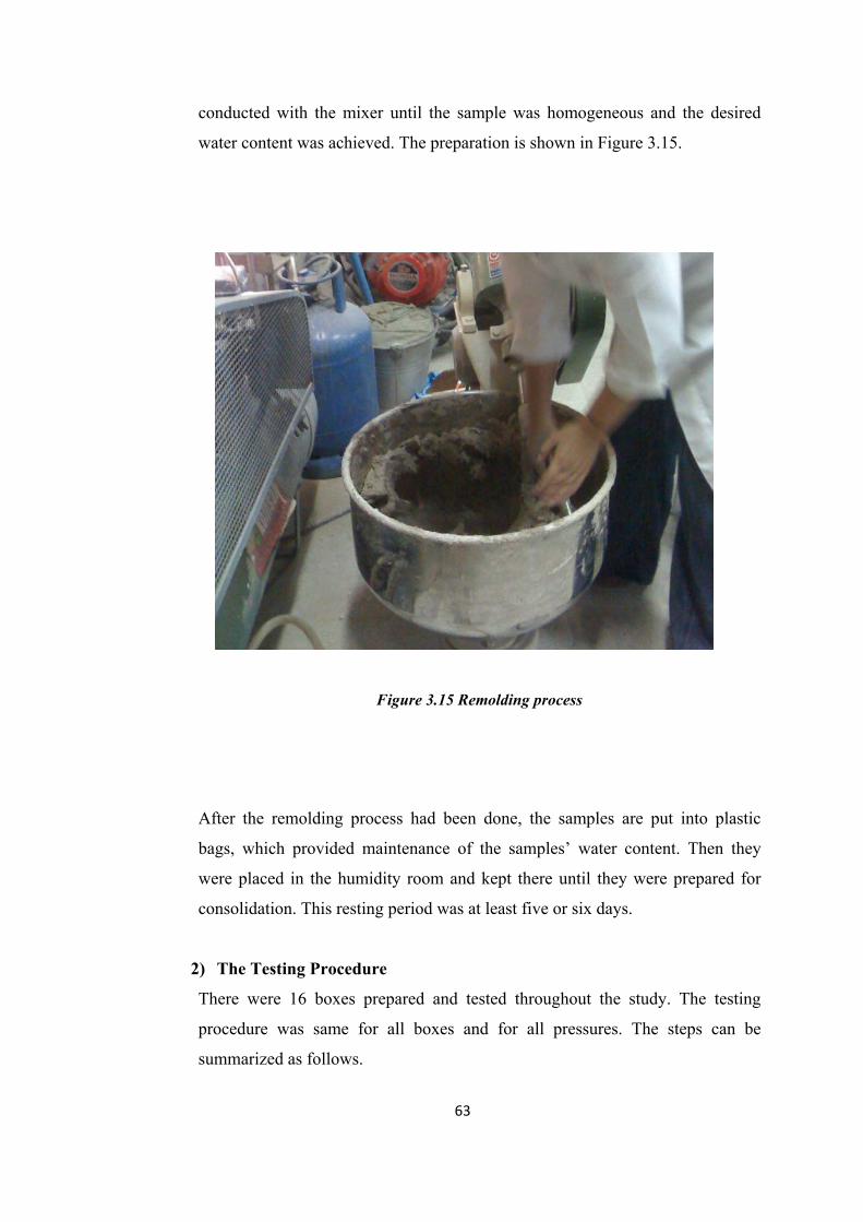
63
conducted with the mixer until the sample was homogeneous and the desired
water content was achieved. The preparation is shown in Figure 3.15.
Figure 3.15 Remolding process
After the remolding process had been done, the samples are put into plastic
bags, which provided maintenance of the samples’ water content. Then they
were placed in the humidity room and kept there until they were prepared for
consolidation. This resting period was at least five or six days.
2) The Testing Procedure
There were 16 boxes prepared and tested throughout the study. The testing
procedure was same for all boxes and for all pressures. The steps can be
summarized as follows.
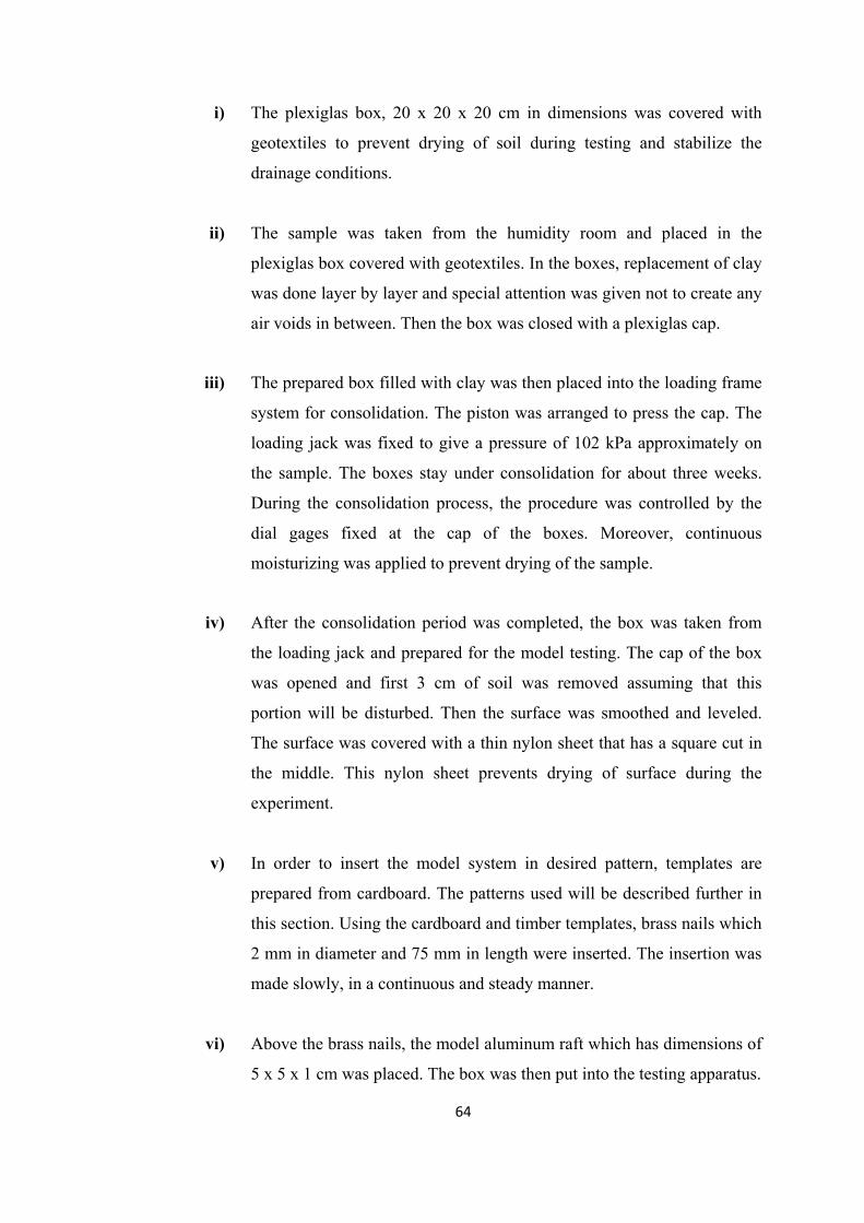
64
i) The plexiglas box, 20 x 20 x 20 cm in dimensions was covered with
geotextiles to prevent drying of soil during testing and stabilize the
drainage conditions.
ii) The sample was taken from the humidity room and placed in the
plexiglas box covered with geotextiles. In the boxes, replacement of clay
was done layer by layer and special attention was given not to create any
air voids in between. Then the box was closed with a plexiglas cap.
iii) The prepared box filled with clay was then placed into the loading frame
system for consolidation. The piston was arranged to press the cap. The
loading jack was fixed to give a pressure of 102 kPa approximately on
the sample. The boxes stay under consolidation for about three weeks.
During the consolidation process, the procedure was controlled by the
dial gages fixed at the cap of the boxes. Moreover, continuous
moisturizing was applied to prevent drying of the sample.
iv) After the consolidation period was completed, the box was taken from
the loading jack and prepared for the model testing. The cap of the box
was opened and first 3 cm of soil was removed assuming that this
portion will be disturbed. Then the surface was smoothed and leveled.
The surface was covered with a thin nylon sheet that has a square cut in
the middle. This nylon sheet prevents drying of surface during the
experiment.
v) In order to insert the model system in desired pattern, templates are
prepared from cardboard. The patterns used will be described further in
this section. Using the cardboard and timber templates, brass nails which
2 mm in diameter and 75 mm in length were inserted. The insertion was
made slowly, in a continuous and steady manner.
vi) Above the brass nails, the model aluminum raft which has dimensions of
5 x 5 x 1 cm was placed. The box was then put into the testing apparatus.

65
vii) In the testing apparatus, the loads corresponding to the desired pressures
were hung to the load hangers. Lvdt’s were placed at two opposite
corners of the thin metal sheet welded at the top of the aluminum
footing. For further checking, a dial gage was also fixed to this thin
metal sheet.
viii) The loading road was then released and simultaneously the software was
started. The recordings were taken more frequently for the first hours,
then the intervals between the readings were increased. The testing
period had been changed from five to ten days, regarding to the testing
model.
3) The Testing Schedule
The three different model systems used in the experiments can be listed as
follows:
The raft foundation alone
The raft foundation consisting of 16 piles (Figure 3.16)
The raft foundation consisting of 49 piles (Figure 3.17)
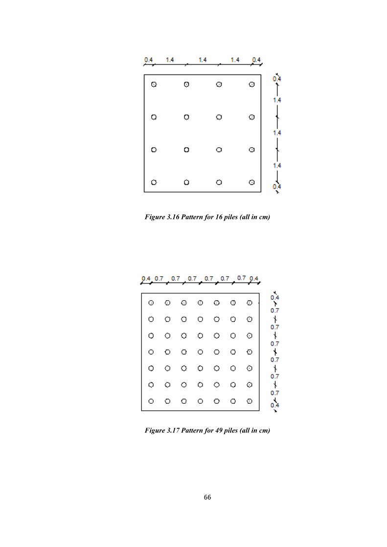
66
Figure 3.16 Pattern for 16 piles (all in cm)
Figure 3.17 Pattern for 49 piles (all in cm)
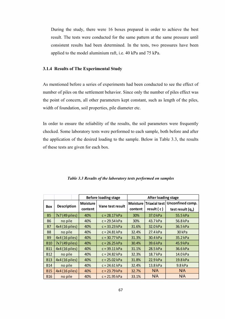
67
During the study, there were 16 boxes prepared in order to achieve the best
result. The tests were conducted for the same pattern at the same pressure until
consistent results had been determined. In the tests, two pressures have been
applied to the model aluminium raft, i.e. 40 kPa and 75 kPa.
3.1.4 Results of The Experimental Study
As mentioned before a series of experiments had been conducted to see the effect of
number of piles on the settlement behavior. Since only the number of piles effect was
the point of concern, all other parameters kept constant, such as length of the piles,
width of foundation, soil properties, pile diameter etc.
In order to ensure the reliability of the results, the soil parameters were frequently
checked. Some laboratory tests were performed to each sample, both before and after
the application of the desired loading to the sample. Below in Table 3.3, the results
of these tests are given for each box.
Table 3.3 Results of the laboratory tests performed on samples
Box
B5B6B7B8B9B10B11B12B13B14B15B16
7x7 (49 piles) 40% c = 28.17 kPa 30% 37.0 kPa 55.5 kPa
Before loading stage After loading stage
DescriptionMoisture content
Vane test resultMoisture content
Triaxial test result ( c )
Unconfined comp.
test result (qu)
4x4 (16 piles) 40% c = 33.23 kPa 31.6% 32.0 kPa 36.5 kPano pile 40% c = 29.54 kPa 30% 43.7 kPa 56.8 kPa
4x4 (16 piles) 40% c = 30.77 kPa 31.3% 30.4 kPa 35.2 kPano pile 40% c = 24.81 kPa 32.4% 27.4 kPa 30 kPa
4x4 (16 piles) 40% c = 39.11 kPa 31.1% 28.5 kPa 36.6 kPa7x7 (49 piles) 40% c = 26.25 kPa 30.4% 39.6 kPa 45.9 kPa
4x4 (16 piles) 40% c = 25.02 kPa 31.8% 22.9 kPa 19.8 kPano pile 40% c = 24.82 kPa 32.3% 18.7 kPa 14.0 kPa
4x4 (16 piles) 40% c = 23.79 kPa 32.7% N/A N/Ano pile 40% c = 24.61 kPa 32.4% 13.8 kPa 9.8 kPa
no pile 40% c = 21.95 kPa 33.1% N/A N/A

68
The settlements of the raft measured for each box is given in Table 3.4. Please note
that, the results presented herein exclude the first four boxes, since they can be
accepted to serve for the calibration purposes.
Table 3.4 Settlements obtained for each box
Box Description Load Measured
settlement
B5 7x7 (49 piles) 75 kPa 1.86 mm
B6 no pile 75 kPa 2.37 mm
B7 4x4 (16 piles) 75 kPa 2.30 mm
B8 no pile 75 kPa 2.74 mm
B9 4x4 (16 piles) 75 kPa 2.05 mm
B10 7x7 (49 piles) 75 kPa 1.80 mm
B11 4x4 (16 piles) 75 kPa 2.11 mm
B12 no pile 75 kPa 2.55 mm
B13 4x4 (16 piles) 75 kPa 2.09 mm
B14 no pile 75 kPa 2.77 mm
B15 4x4 (16 piles) 40 kPa 1.29 mm
B16 no pile 40 kPa 1.91 mm
The consistency of the results can be seen in the Figure 3.18. Since, the experimental
data is consistent with each other, the average values can be taken as representative
of the behavior. The graphs given in Figures 3.19 and 3.20, respectively for 40 kPa
and 75 kPa, show the settlement behavior and pile number relationship.
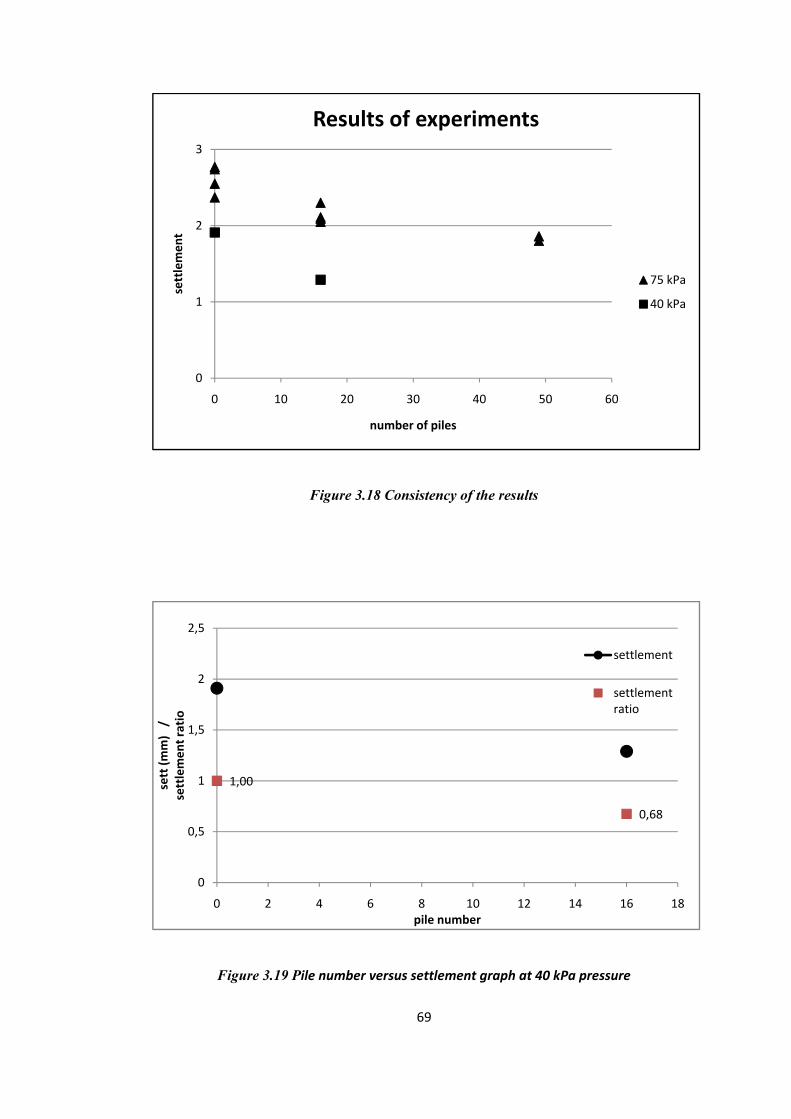
69
Figure 3.18 Consistency of the results
Figure 3.19 Pile number versus settlement graph at 40 kPa pressure
0
1
2
3
0 10 20 30 40 50 60
settlemen
t
number of piles
Results of experiments
75 kPa
40 kPa
1,00
0,68
0
0,5
1
1,5
2
2,5
0 2 4 6 8 10 12 14 16 18
sett (m
m)/
settlemen
t ratio
pile number
settlement
settlement ratio

70
Figure 3.20 Pile number versus settlement graph at 75 kPa pressure
By observing Figure 3.20, reasonable and applicable results can be obtained. It can
clearly be seen that increasing number of piles does not necessarily decrease the
settlement at a considerable amount, thus from a point the behavior tend to turn into
a steady phase.
When the dimensions of the raft is considered, the models used for the experiments
can be said to be the ones which have the maximum number of piles, i.e. 49 piles and
the average number of piles, i.e. 16 piles. The raft without piles can be accepted as a
reference data, however the values obtained are very useful for interpretation of the
test data. Thus, considering the results of these series of experiments, it can be said
that after an optimum point, placing more piles below the raft does not have a
considerable influence on the settlement. When raft is adequate for capacity, addition
of piles has a significant positive effect from settlement point of view. However,
adding piles in excess numbers is unnecessary.
1,00
0,760,67
0
0,5
1
1,5
2
2,5
3
0 10 20 30 40 50 60
sett (m
m)/
settlemen
t ratio
pile number
settlement
settlement ratio

71
It should further be noted that, in the experimental study, the model piles had been
yielded, so the factor of safety values for model piles were most likely very close to
unity. The model piles in the system behaved like settlement reducing piles.
These results gathered from the experimental study will be compared with the
analytical studies on settlement reducing piles which will further be described in the
next section.
3.2 The Analytical Studies on Settlement Reducing Piles
As mentioned before, though the concept of pile foundations has first been developed
to solve settlement problems, capacity based design was the general trend. Because
of that, settlement analysis did not receive any attention, thus the present methods of
settlement analysis are generally not very sophisticated. However, nowadays
engineers have begun to realize the importance and advantages of the settlement
based design methods. So, the settlement reducing piles become one of the recent
trends. In order to analyze these kinds of systems, analysis procedures which take
into account some important aspects should be used. These aspects can be
summarized as follows:
• The load sharing between raft and piles should be taken into account since the
bearing capacity problem can only be solved by the raft and piles carry a
lower portion of the total load.
• The factor of safety values for the piles, the raft and the system should be
taken into account separately, since factor of safety for piles will be taken as
unity.
• Separate stiffness values for piles, raft and the system should be taken into
account since each element of the system has different functions and
contributions to the system.
• The analysis method should permit the mobilization of the full capacity for
the piles in the system.

72
There have not been too many methods of analysis which satisfy the required aspects
and suitable for settlement reducing piles. However, this kind of analysis can easily
be coped with boundary element approaches which are available with some codes
written by some researchers. Though there are a few analytical approaches that can
be managed with simple hand calculations.
Some methods in the literature which can be used in settlement analysis for these
systems were discussed in Chapter 2. These can be listed as follows:
• Fleming et al., 1992
• Clancy and Randolph, 1993
• De Sanctis, 2002
In this chapter, method proposed by Clancy and Randolph will be used. The results
will be checked according to the behavior obtained from the experimental study.
3.2.1 Clancy and Randolph, 1993
The model that has been used in this chapter has dimensions proportional with the
model used in the experiments, the materials and soil properties remain same as the
experimental study.
There have been three systems analyzed; the raft foundation alone, raft with 16 piles,
raft with 49 piles and raft with 81 piles. The patterns for 16 piles and 49 piles are
shown in Figures 3.21 and 3.22.

Figure 3.2
Figure 3.2
73
21 Pattern fo
22 Pattern fo
3
for 16 piles (a
for 49 piles (a
all in m)
all in m)

74
The raft is 50 x 50 x 10 m in dimension and piles are 2 m in diameter and 75 m in
length. The material properties of raft and soil are kept constant. Also properties and
classification of soil have been kept constant.
The idea behind the method is calculating an overall stiffness for the system derived
from the separate stiffness of both pile and raft. The calculations are made using the
formulae given in Section 2.1.3.2 as Equations 11 to 17. These formulae have also
been presented below.
2.5 1
2
ln
21
1ln
ln 2
1 2
1
In above formulation, ρ value is calculated by dividing shear modulus at the half
length of the pile to the shear modulus at the total length of the pile and I is the
influence factor for the raft which is taken from the related tables given in Appendix
D.

75
The values used in the settlement calculation are showed in Table .3.5.
The settlement calculation of the models based on the mentioned method is presented
in Table 3.6. Also settlement of the unpiled raft values are presented in mentioned
table as wur.
Table 3.5 Properties of the model
Raft
B (m) 50
t (m) 10
νr 0.35
Pile
I (cap) 0.82
d (m) 2
L (m) 75
ro (m) 1
rm (m) 80.96591
Soil
GL (kPa) 8250
ρ 0.86
νs 0.5

76
Table 3.6 Settlement calculation of the model
Press. (kPa)
n (# of piles)
kr kp αrp αpr kpr wpr (cm)
wur (cm)
75 kPa
raft alone 1266416.51 884773.77 ‐ ‐ ‐ 14.8 14.816 (4x4) 1266416.51 884773.77 0.369 0.528 1511062 12.4 14.849 (7x7) 1266416.51 884773.77 0.114 0.164 1897177 9.9 14.881 (9x9) 1266416.51 884773.77 ‐1E‐04 ‐1E‐04 2151433 8.7 14.8
40 kPa
raft alone 1266416.51 884773.77 ‐ ‐ ‐ 7.9 7.9 16 (4x4) 1266416.51 884773.77 0.369 0.528 1511062 6.6 7.9 49 (7x7) 1266416.51 884773.77 0.114 0.164 1897177 5.3 7.9 81 (9x9) 1266416.51 884773.77 ‐1E‐04 ‐1E‐04 2151433 4.6 7.9
For further checking of the values of αrp and αpr, two other formulae can be used.
These were also given in Section 2.1.3.2 with Equations 18 and 19.
The load sharing between raft and piles is given by Fleming et al., 1992.
Thus, the recalculation of the αrp and αpr values is given in Table 3.7.
As seen from the table below, the values are nearly the same with the values found
formerly. So, the values have been crosschecked.
(83)

77
Table 3.7 Recalculation of the α values
Pr / (Pr + Pp) Pr (kN) Pp (kN) αrp αpr
75 kPa 16 piles 0.657 123160.22 64339.78 0.368 0.527 49 piles 0.602 112968.41 74531.59 0.116 0.165 81 piles 0.589 110437.50 77062.50 ‐0.002 ‐0.001
40 kPa 16 piles 0.657 65685.45 34314.55 0.364 0.525 49 piles 0.602 60249.82 39750.18 0.121 0.170 81 piles 0.589 58900.00 41100.00 ‐0.011 ‐0.010
3.2.2 Results of The Settlement Analysis of Settlement Reducing Piles
Since the concept of settlement reducing piles is recently developed, there are a few
methods and some codes which can be considered suitable for this kind of analysis.
In this study, the analyses have been made using only the method presented by
Clancy and Randolph, 1993.
The resulting settlements calculated by aforementioned method have already been
given in Table 3.6. The figures presenting the relationship between the settlement
and pile number are given in Figures 3.23 and 3.24 for pressures of 75 kPa and 40
kPa respectively.
In these figures, it can be seen that though adding piles to the raft decreases
settlement to the desired amount, there can be seen a tendency to turn into a straight
line.
However, it can be seen that this mentioned behavior is not very similar to the
behavior derived at the experimental study. The comparison and discussion related to
the settlement behaviors obtained from both experimental and analytical studies will
be given further in Chapter 5.
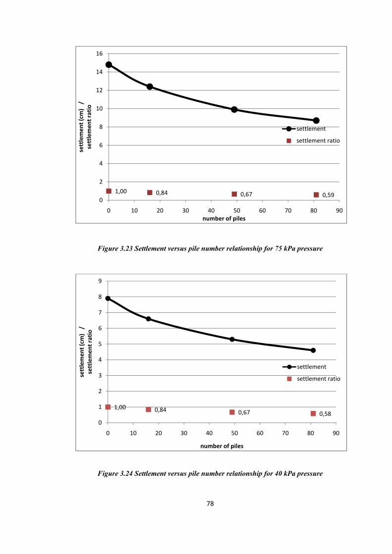
78
Figure 3.23 Settlement versus pile number relationship for 75 kPa pressure
Figure 3.24 Settlement versus pile number relationship for 40 kPa pressure
1,00 0,84 0,67 0,590
2
4
6
8
10
12
14
16
0 10 20 30 40 50 60 70 80 90
settlemen
t (cm
)/
settlemen
t ratio
number of piles
settlement
settlement ratio
1,00 0,84 0,67 0,580
1
2
3
4
5
6
7
8
9
0 10 20 30 40 50 60 70 80 90
settlemen
t (cm
)/
settlemen
t ratio
number of piles
settlement
settlement ratio

79
CHAPTER 4
SETTLEMENT ANALYSIS OF PILED RAFT FOUNDATIONS
4.1 The Piled Raft Foundation Models Used For The Analysis
In this chapter of the aforementioned study, the settlement of piled raft will be
analyzed using some simple hand calculations and a finite element analysis software.
The main goal of the research is showing the effect of pile number to the settlement
behavior of the piled raft foundations.
For the analysis made for investigating the settlement behavior of the piled raft
foundations, a simple model has been used with increasing pile number. Thus, a
residential building with no basement will be supported by a piled raft foundation.
The load transferred to the base is 450 kPa.
The model consists of a rectangular raft with dimensions of 24 x 28 m and thickness
of 2 m. The diameter of piles is 1 m. The analyses have been made in two sets; for
the first set pile length has been 25 m, whereas for the second set it has been 30 m.
Table 4.1 shows the pile numbers considered for each set. Please note that, the
marked values are applied only for the finite element analyses.

80
Table 4.1 Pile numbers considered for each set
Set Pile length Number of piles
1 L = 25 m
143 (13x11) 120 (12x10) 99 (11x9) 80 (10x8) *
2 L = 30 m
120 (12x10) 99 (11x9) 80 (10x8) 63 (9x7) *
At both sets for all of the different models considered pile spacing is kept as 2.25 m.
Moreover, for the whole case; the ultimate shaft capacity of the piles is taken as
197.92 kN / m and the ultimate end bearing capacity is taken as 989 kN.
The modulus of elasticity for the piles and the raft has been accepted as 3x10⁷ kPa;
Poisson’s ratio value is 0.1 and the unit weight is 2400 kg / m3.
The soil beneath the desired construction is normally consolidated medium clay
which has an increasing modulus of elasticity with depth. The properties of the soil
medium are tabulated below in Table 4.2. The properties are decided according to the
commonly used cases for soil conditions under this type of buildings. Please note
that it is assumed that no water table is encountered.

81
Table 4.2 Properties of the soil used in the analysis
cu undrained shear strength 140 kPa c' appearent cohesion 5 kPa
Eu undrained modulus of elasticity 40 MPa
E modulus of elasticity 30 MPa at the surface, increasing linearly with 500 kPa for 1 m depth
Φ' friction angle 25o
νu undrained Poisson's ratio 0,35 ν Poisson's ratio 0,20
mv coefficient of volume compressibility 0.0005 cm2 / kg
γ unit weight of soil 20 kN / m3
α skin friction factor 0.45o
4.2 Analytical Studies For Settlement Calculation of Piled Raft Foundations
The general concepts and methods regarding to the settlement based design have
been explained in detail in Section 2.2.
As mentioned before, the methods that can be used for analysis can be classified as
follows:
1) Purely empirical techniques that relate settlement of the group to that of a
single pile
2) Simplified techniques that reduce the pile group system to an equivalent raft
3) Analytical methods that consider interaction between piles and the
surrounding soil
In this thesis and further in this chapter, the methods fall into the first and third
categories have been used for the analysis. This is because the methods fall into the
second category, do not give ideas about the settlement behavior and the settlement
versus pile number relationship, although they can predict settlement.

4.2.1 Sett
The metho
the applica
This meth
pile numb
from an e
group, the
The formu
where, S =
P = averag
n = numbe
K = the gr
where, f =
k = individ
where, e =
A)
The expon
• Le
tlement Ra
od used her
ations of the
hod is based
ber and stiffn
efficiency fa
e soil proper
ulation will
= the group
ge load per
er of piles in
roup stiffnes
= efficiency
dual pile sti
= the expon
nent,e is dep
ength to dia
atio Method
rein was pro
e method is
d on the be
fness of the
factor which
rties (like Po
be given be
settlement
pile
n a group
ss
iffness
nent which
pended upon
ameter ratio
82
d
oposed by B
s presented i
elief that se
pile group.
h considers
oisson’s rat
elow.
can be obta
n some fact
of the pile
2
Butterfield a
in Ergun (1
ttlement of
The pile gr
the effect
tio) and dim
ained by so
tors like;
and Dougla
995).
f the pile gr
roup settlem
of the num
mensional co
ome charts (
s (1981) an
roup is rela
ment can be
mber of pile
onstant of th
(given in A
(
(
nd one of
ated with
e derived
es in the
he raft.
Appendix
(84)
(85)
(86)

83
• λ, pile stiffness ratio (Ep / Gs )
• Spacing of the pile
• Slope of the stiffness increase with depth
• Poisson’ s ratio
Throughout the study, the exponential “e” has been calculated as given in Table 4.3.
Using the calculated values for e, settlements of the model piled raft for different pile
numbers have been calculated. The calculated settlement values for single pile are
given as w1. Calculations are tabulated in Table 4.4.
Table 4.3 Calculation for the exponential e
Table 4.4 Settlement calculation for the settlement ratio analysis
n s (m) d (m) ν GS (kPa) EP (kPa) λ ρ e13x11 143 2.25 1 0.2 18750 3E+07 1600 0.853 0.6810x12 120 2.25 1 0.2 18750 3E+07 1600 0.853 0.689x11 99 2.25 1 0.2 18750 3E+07 1600 0.853 0.68
n s (m) d (m) ν GS (kPa) EP (kPa) λ ρ e10x12 120 2.25 1 0.2 18750 3E+07 1600 0.833 0.6829x11 99 2.25 1 0.2 18750 3E+07 1600 0.833 0.6828x10 80 2.25 1 0.2 18750 3E+07 1600 0.833 0.682
L=25
mL=30
m
Length nP (load per pile)
s (m) e f (n-e) w1 (m) k (kN/m) K S (m) S (cm)
143 2340.25 2.25 0.68 0.0342 0.00353 662421.9 3242218 0.103 10.32120 2788.80 2.25 0.68 0.0386 0.00421 662421.9 3065298 0.109 10.9299 3380.36 2.25 0.68 0.044 0.0051 662421.9 2882292 0.116 11.61120 2788.80 2.25 0.682 0.0382 0.00363 767528.4 3517824 0.095 9.51399 3380.36 2.25 0.682 0.0435 0.0044 767528.4 3309074 0.101 10.1180 4183.20 2.25 0.682 0.0504 0.00545 767528.4 3092268 0.108 10.82
30 m
25 m

4.2.2 Mod
This meth
load-defor
methods. U
simple spr
The formu
from Equa
Some of th
dified Meth
hod is based
rmation ch
Using this m
read sheet c
ulae used fo
ation 64 to E
hese equatio
hod By She
d on the pr
haracteristics
method, set
calculations.
for this meth
Equation 82
ons are also
84
en and Teh
rinciples of
s of the s
ttlement beh
.
hod had be
2.
o stated belo
4
h, 2002
f the load tr
soil can be
havior obse
een explaine
ow.
ransfer curv
e modeled
ervation can
ed in detail
ves. The no
with this
n be overco
l at Section
on-linear
type of
ome with
n 2.2.3.3,

The calcu
respective
ulations are
ely. Settleme
given in t
ents obtaine
85
tables 4.5 a
ed are tabul
5
and 4.6 for
ated below
r 25 m pile
as Table 4.
es and 30
7.
m piles,

86
Table 4.5 Settlement calculations of 25 m long piles for load transfer curve analysis
np l/ro ρ λ νs s/ro ξ143 50 0.853 1694.12 0.2 4.5 1
ζ αp αpb μs μb μp4.45 4.203 27.012 148.3608 135.06 15221.6
388.1636 119.2821 77.09818119.2821 15298.69 16227.4677.09818 16227.46 20340.260.002588 ‐6.4E‐05 4.09E‐05‐6.4E‐05 0.000427 ‐0.000344.09E‐05 ‐0.00034 0.00032
[H] =P/Glrowt =
↓
[H]‐1 = 383.2789219
np l/ro ρ λ νs s/ro ξ120 50 0.853 1694.12 0.2 4.5 1
ζ αp αpb μs μb μp4.45 3.874 24.483 136.7475 122.42 12773.4
355.7063 109.945 71.06313109.945 12844.43 13700.571.06313 13700.5 17072.450.002826 ‐8.1E‐05 5.31E‐05‐8.1E‐05 0.000543 ‐0.000445.31E‐05 ‐0.00044 0.000408
[H] =P/Glrowt =
↓
[H]‐1 = 350.8570716
np l/ro ρ λ νs s/ro ξ99 50 0.853 1694.12 0.2 4.5 1
ζ αp αpb μs μb μp4.45 3.54 21.965 124.9577 109.83 10538
323.0029 100.466 64.93637100.466 10602.96 11385.2364.93637 11385.23 14088.440.003115 ‐0.00011 7.18E‐05‐0.00011 0.000717 ‐0.000587.18E‐05 ‐0.00058 0.000538
[H] =P/Glrowt =
↓
[H]‐1 = 318.2000431

87
Table 4.6 Settlement calculations of 30 m long piles for load transfer curve analysis
np l/ro ρ λ νs s/ro ξ120 60 0.833 1600 0.2 4.5 1
ζ αp αpb μs μb μp4.605 3.532 24.483 144.5747 122.42 10053.1
363.2764 112.3827 72.23914112.3827 10125.34 11009.372.23914 11009.3 13445.860.002775 ‐0.00013 9.4E‐05‐0.00013 0.000906 ‐0.000749.4E‐05 ‐0.00074 0.000681
[H] =P/Glrowt =
↓
[H]‐1 = 356.933723
np l/ro ρ λ νs s/ro ξ99 60 0.833 1600 0.2 4.5 1
ζ αp αpb μs μb μp4.605 3.263 21.965 133.5637 109.83 8293.8
332.3422 103.8235 66.73735103.8235 8360.542 9177.18266.73735 9177.182 11096.960.003041 ‐0.00019 0.00014‐0.00019 0.001309 ‐0.001080.00014 ‐0.00108 0.000984
[H] =P/Glrowt =
↓
[H]‐1 = 325.9925974
np l/ro ρ λ νs s/ro ξ80 60 0.833 1600 0.2 4.5 1
ζ αp αpb μs μb μp4.605 3.02 19.46 123.6171 97.3 6702.06
303.246 96.09167 61.7673396.09167 6763.832 7519.65561.76733 7519.655 8971.770.003349 ‐0.00032 0.000247‐0.00032 0.002199 ‐0.001840.000247 ‐0.00184 0.001653
[H] =P/Glrowt =
↓
[H]‐1 = 296.8214261

88
Table 4.7 Settlement values for load transfer curve analysis
4.2.3 Results of The Analytical Studies on Piled Raft Foundations
1) Settlement Ratio Method (Butterfield and Douglas, 1981)
The graphical results obtained are given in Figure 4.1.
Analyzing the figure, it can be seen that for both pile lengths the settlement
decreases as pile number increases as expected. However, the rate of this
decrease in settlement reduces as the pile number increases, in other words, the
effect of increasing the pile number at the settlement behavior gets more inactive.
This issue points out itself even more in the case of longer piles.
2) Load Transfer Curves (Shen and The, 2002)
The graphical results obtained are given in Figure 4.2.
When this figure is analyzed, a similar relationship with Figure 4.1 can be seen.
The decrease rate reduces in this figure too; however this is not very noticeable.
Though, a tendency to straighten the curve can be seen at the closing. Another
point to mention is that the settlement behavior is almost the same even if the
lengths of the piles are different.
The results of the simple hand calculations regarding to the piled raft foundations
have further been checked with finite element analysis software. This analysis will be
Set Pile length Pile number P (kN) Gl (kPa) ro (m) P/Glrowt wt (m) wt (cm)
143 302400 17708,33 0,5 383,2789 0,089109 8,91120 302400 17708,33 0,5 350,8571 0,097343 9,7399 302400 17708,33 0,5 318,2 0,107333 10,73120 302400 17708,33 0,5 356,9337 0,095686 9,5799 302400 17708,33 0,5 325,9926 0,104767 10,4880 302400 17708,33 0,5 296,8214 0,115064 11,51
1 25 m
2 30 m

89
explained later in this chapter. The discussion between the results of different
methods and finite element analysis will be given in Chapter 5.
Figure 4.1 Graphical results for settlement ratio method
6
7
8
9
10
11
12
70 80 90 100 110 120 130 140 150
settlemen
t (cm
)
number of piles
L = 30 m
L=25 m

90
Figure 4.2 Graphical results for load transfer curve analysis
4.3 Finite Element Analysis For Estimating Settlement of Piled Raft Foundations
Finite element analysis is one of the complete analysis methods. Some problems
encountered in previously mentioned methods can easily be overcome by complete
analysis. Other type of complete analysis is boundary element analysis. The complete
analysis can be achieved by some special software and codes.
Comparing to all other methods mentioned, finite element analysis is the most time
consuming one and it needs more money and much effort for data preparation than
the others. However, this kind of analysis helps to determine the load transfer
behavior and the settlement distribution.
6
7
8
9
10
11
12
70 80 90 100 110 120 130 140 150
settlemen
t (cm
)
number of piles
L=30 m
L=25 m

91
In the aforementioned study, in order to check and support the behavior derived from
simple hand calculations, a finite element analysis software has been used.
4.3.1 Analysis Using Plaxis 3D Foundation
This software is a 3 dimensional finite element analysis program which all types of
foundation structures can be modeled and analyzed with. Special foundation types
and elements can be modeled easily. Program is one of the most user-friendly
programs in the market since the input procedures and modeling steps can be done
with graphical interfaces. It also has a wide range of professional output facilities.
In the scope of this study, the model presented previously in this chapter at section
4.1, has been analyzed using this software. All the parameters entered for modeling
the foundation system have already been given in Table 4.2.
In the analysis, Mohr-Coulomb failure criteria had been used and drained analysis
had been made since in the soil profile no water table is encountered.
There have been eight models analyzed in two sets as given in Table 4.1. In order to
serve as an example, the model designed for 120 piles with lengths of 25 m after
meshing is given in Figure 4.3.
After running the program, the output graphs obtained for sets 1 and 2, are given
below in Figures 4.4 to 4.11.

92
Figure 4.3 Model designed for 120 piles in Plaxis 3D Foundation
Figure 4.4 Output graph for 143 piles L=25 m

93
Figure 4.5 Output graph for 120 piles L=25 m
Figure 4.6 Output graph for 99 piles L=25 m

94
Figure 4.7 Output graph for 80 piles L=25
Figure 4.8 Output graph for 120 piles L=30 m
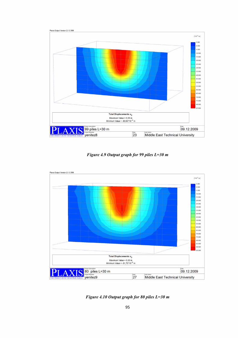
95
Figure 4.9 Output graph for 99 piles L=30 m
Figure 4.10 Output graph for 80 piles L=30 m

96
Figure 4.11 Output graph for 63 piles L=30 m
4.3.2 Results of The Finite Element Analysis of The Piled Raft Foundations
The results obtained from 3 dimensional finite element analysis software Plaxis 3D
Foundation is given below as Table 4.8.
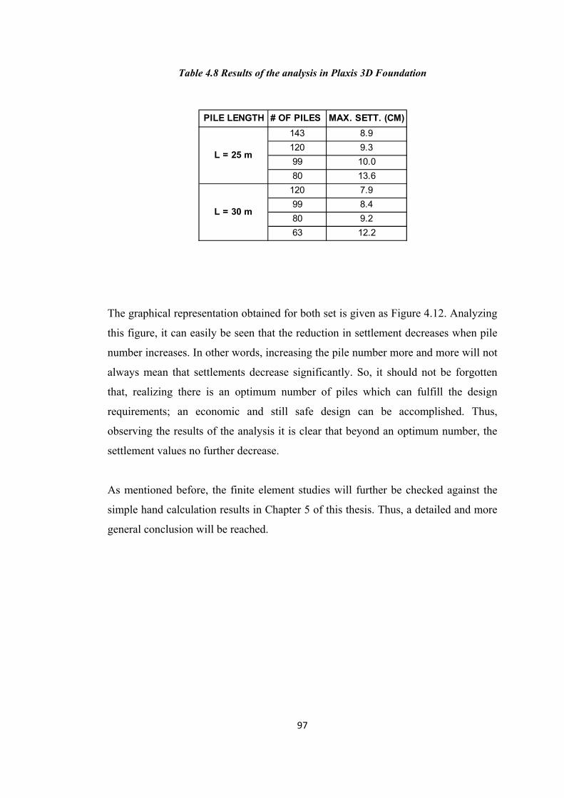
97
Table 4.8 Results of the analysis in Plaxis 3D Foundation
The graphical representation obtained for both set is given as Figure 4.12. Analyzing
this figure, it can easily be seen that the reduction in settlement decreases when pile
number increases. In other words, increasing the pile number more and more will not
always mean that settlements decrease significantly. So, it should not be forgotten
that, realizing there is an optimum number of piles which can fulfill the design
requirements; an economic and still safe design can be accomplished. Thus,
observing the results of the analysis it is clear that beyond an optimum number, the
settlement values no further decrease.
As mentioned before, the finite element studies will further be checked against the
simple hand calculation results in Chapter 5 of this thesis. Thus, a detailed and more
general conclusion will be reached.
PILE LENGTH # OF PILES MAX. SETT. (CM)143 8.9120 9.399 10.080 13.6
120 7.999 8.480 9.263 12.2
L = 25 m
L = 30 m
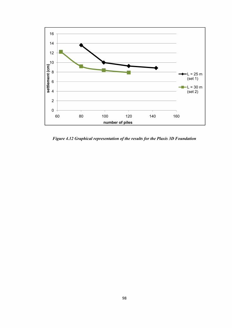
98
Figure 4.12 Graphical representation of the results for the Plaxis 3D Foundation
0
2
4
6
8
10
12
14
16
60 80 100 120 140 160
settl
emen
t (cm
)
number of piles
L = 25 m (set 1)
L = 30 m (set 2)
99
CHAPTER 5
DISCUSSION OF RESULTS
5.1 General Concepts
In some cases, bearing capacity problem can easily be solved by using raft
foundations. However, when settlement values are beyond the tolerable limits, raft
foundation can be used together with pile foundations. Nowadays, with increasing
technology and some sophisticated engineering design and decisions, the best
solution appears to be combined foundations in which piles are used together with
rafts. This solution gives safe, economical and efficient design.
In this thesis, the effect of pile number to the settlement behavior of piled rafts and
settlement reducing piles had been researched. For both of the systems, it is very
clear that beyond an optimum number of piles, settlement no longer decreases. So,
using an excessive number of piles below the raft will not achieve the safest solution.
In the aforementioned study, besides analytical simple hand calculations,
experimental works were conducted to see the effect for settlement reducing piles
and finite element analyse were done to see the effect for piled raft foundations.
In this chapter, the results obtained from all the studies will be discussed separately
for settlement reducing piles and piled raft foundations in two parts.
5.2 Discussion of Results For Settlement Reducing Piles
In cases when raft foundation alone satisfies the bearing capacity criteria, piles may
be needed for settlement requirements. Since these piles have no benefit to the
bearing capacity, their full capacities can be mobilized and they can be permitted to
100
yield. In other words, the factor of safety against bearing capacity failures for piles in
the system can be taken almost unity. Thus, these piles will only serve as settlement
reducers. In such systems, since piles yield, the major portion of the load is carried
by the raft. So, the load distribution between piles and the raft becomes important.
There are few methods which can manage this kind of analysis. Such methods should
consider the load distribution between piles and raft and the stiffness for each
element in the system should be taken separately.
In the experimental studies conducted, the piles had been yielded resulting in such a
behavior same as the settlement reducing piles. In the experimental studies, a system
consists of a raft model 50 x 50 x 10 mm in dimensions was used together with
model piles which are 2 mm in diameter. The soil medium was kaolin type of clay on
which all necessary laboratory tests had been conducted to specify and classify. The
classification was determined as low plasticity clay with Gs = 2,60. Tests were
conducted at two pressure levels namely 75 kPa and 40 kPa. Under 75 kPa pressure;
raft alone, raft with 16 piles and raft with 49 piles were tested, whereas under 40 kPa
only raft alone and raft with 16 piles were tested. The observed settlements are in the
range of 2.70 to 1.80 mm under 75 kPa pressure, while the range become 1.91 to
1.29 mm under 40 kPa pressure. The settlement behavior observed clearly
demonstrates that settlement decreases with increasing pile number only up to an
optimum number, beyond that number decrement in the settlement becoming very
small that it no longer posses any importance.
As described earlier there is an analytical approach used for settlement reducing
piles. Instead of using model raft and model pile diameters in mm, they are scaled
and system is modeled keeping the pressure units same. The raft dimensions are 50 x
50 m. The pile diameter is 2 m and 16, 49 and 81 piles are analyzed. The applied
pressures were 75 and 40 kPa. The undrained shear strength of the soil medium is
kept as around 30 kPa and the coefficient of volume compressibility was around
0.0001 to 0.0004 m2/kN. The method used was proposed by Clancy and Randolph in
1993. The importance of this method is that the stiffness of the system as a whole is
calculated using separate stiffness of pile and raft. The calculated settlements were in

101
the range of 14.8 to 8.7 cm under 75 kPa, whereas under 40 kPa pressure they were
in the range of 7.9 to 4.6 cm. In the results observed from this method, the effect of
inserting piles on the settlement of foundations can be observed. An idea about the
settlement behavior can also be hold.
Although experimental and analytical results cannot be compared directly, trends in
settlement reduction are interesting. A parameter called settlement reduction factor, ρ
was used in the figures. This parameter is calculated by dividing settlement of the
raft with piles to the settlement of the raft alone. This parameter shows for each pile
number, how much the settlement is reduced when using that number of piles. As
this ratio gets closer to unity, this shows that, the settlement of the raft including piles
gets closer to that of the raft alone. Obviously, a smaller value for this ratio is better
but, it should not be forgotten that there are acceptable limits for settlements, thus
decreasing this ratio to very small values has no benefits at the same time it increases
the money and time that should be spend. Moreover, it is obvious that beyond a limit,
further decreasing this ratio has a very small effect on settlement behavior.
In Table 5.1, ρ values for the experimental studies and analytical calculations are
given. The graphical representation is shown in Figure 5.1.
Table 5.1 ρ values for the experimental studies and analytical
number of
piles ρ
Clancy and Randolph' 93
0 1 16 0.838 49 0.668 81 0.588
experimental studies
0 1 16 0.756 49 0.665
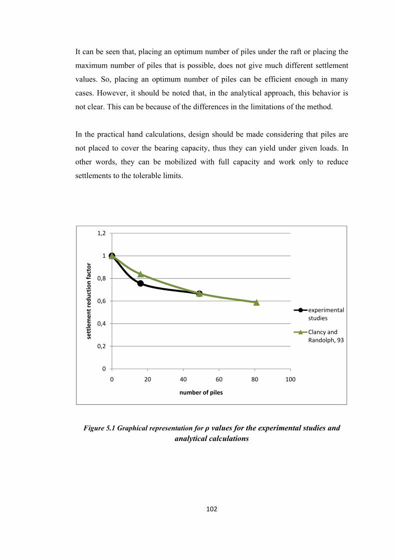
102
It can be seen that, placing an optimum number of piles under the raft or placing the
maximum number of piles that is possible, does not give much different settlement
values. So, placing an optimum number of piles can be efficient enough in many
cases. However, it should be noted that, in the analytical approach, this behavior is
not clear. This can be because of the differences in the limitations of the method.
In the practical hand calculations, design should be made considering that piles are
not placed to cover the bearing capacity, thus they can yield under given loads. In
other words, they can be mobilized with full capacity and work only to reduce
settlements to the tolerable limits.
Figure 5.1 Graphical representation for ρ values for the experimental studies and analytical calculations
0
0,2
0,4
0,6
0,8
1
1,2
0 20 40 60 80 100
settlemen
t red
uction
factor
number of piles
experimental studies
Clancy and Randolph, 93

103
5.3 Discussion of Results For Piled Raft Foundations
In the past, pile foundations were used mostly for providing bearing capacity. This
common use lead to design procedures based on bearing capacities of piles where a
simple check is done for settlement. However, recently, the effects of the piles on
the settlement of foundations have been receiving attention. Thus, the concept of
piled resisted rafts where bearing capacity criteria is satisfied by raft mostly, the
settlement criteria is satisfied by piles. It should not be forgotten that when analyzing
this kind of foundations, the pile number should be taken into consideration. This is
necessary because usually higher factor of safety values are used for piles and no
attention is given to the tolerable settlements.
Since the scope of this thesis is analyzing the settlement behavior of piled
foundations considering the pile number, only methods considering pile number have
been used. As mentioned before, the methods that have been used for settlement
prediction of pile groups can be classified in three categories; the methods that relate
group settlement to that of a single pile, the ones which consider system as an
equivalent raft and finally the methods which take into account the interaction
between piles and soil.
In this thesis, two methods which fall into the first category and a finite element
analysis program which makes a complete analysis and cover the interaction between
piles and soil have been used.
One of the methods used was the method proposed by Butterfield and Douglas in
1981. This method calculates the group stiffness by considering the single pile
stiffness, number of piles and an efficiency factor which is dependent to spacing of
piles, Poisson’s ratio, etc. The raft is 24 x 28 x 2 m. Two sets of piled raft foundation
models have been used. One set comprised of piles which 25 m in length whereas for
the other set pile lengths were 30 m. In the first set there were three patterns having
143, 120 and 99 piles. In the second set again three patterns were used with 120, 99
and 80 piles. The spacing is kept as 2.25 m for all cases. The soil is medium clay
with increasing modulus of elasticity. The resulting settlements were in the range of

104
10.32 to 11.61 cm for set 1 and in the range of 9.51 to 10.82 cm for set 2. Further
analyzing these results given in Figure 4.2, it can be seen that for both sets the curve
that shows the pile number settlement relationship behaves less steep in the second
portion. In other words, the reduction in settlement behavior becomes less effective
as pile number increases, so excessive numbers of piles is not necessary for an
efficient design.
Another analytical approach used was based on load transfer curves. It was proposed
by Shen and Teh in 2002. This method permits non-linear deformation analysis. In
this method, same models have been used. There still were two sets each have three
different patterns. Dimensions of the raft were still 24 x 28 x 2 m. The patterns,
spacing and properties of soil and materials remain same. The first set, in which pile
lengths are taken as 25 m, the results came out in the range of 8.91 to 10.73 cm. In
the second range where the pile lengths were 30 m, the range was between 9.57 and
11.51 cm. From Figure 4.2, the graphical results show that the settlement difference
becomes smaller as pile number increases. In the graphs, the tendency of the curve to
straighten can be seen clearly.
In order to support the analytical calculations, a finite element analysis was made
using Plaxis 3D Foundation software. The model, its dimensions, patterns and soil
and material properties were kept exactly the same. In the software, the Mohr
Coulomb failure criterion has been used and drained analysis was activated. Pile
numbers are 143, 120, 99 and 80 for 25 m length; 120, 99, 80 and 63 for 30 m length.
The results show a settlement range of 8.86 to 13.63 cm in case of piles with 25 m
lengths. As in the case of 30 m long piles, second set, the settlement range become
7.92 to 12.24 cm. The settlement ranges were very small. Also, from Figure 4.12,
analyzing the curves derived from the finite element analysis clearly demonstrates
that, the curve representing the relationship between settlement and the pile number
loses its steep slope as pile number increases. This issue becomes even clearer in the
case of shorter piles.
The all three methods used in this thesis for estimating the settlement behavior of the
piled raft foundations analyzes the same models. This allows comparison between

105
their results and discussion of the findings. The combined results evaluated from
settlement ratio method, load-transfer curves and finite element analysis are given
below in Table 5.2. The graphical representations of the results obtained from all
methods are given in Figures 5.2 and 5.3 respectively, for pile lengths of 25 m and 30
m. When this data are analyzed it can be seen that in general, finite element analysis
gives lower results. This difference appears more strict for longer piles, thus for the
case of 25 m piles, the calculated values from the load transfer curve methods were
very close to the finite element analysis. Among the methods used in the thesis for
piled raft foundations, the most detailed and time consuming method is finite element
analysis. In other words, it can be said that the most sophisticated analysis gives the
smaller results. In general, the load transfer curve analysis and settlement ratio
method give very similar results. However, the results appear to be overestimated
when compared to the results gathered from Plaxis 3D Foundation software.
In all methods considered it is observed that adding more piles under the raft does
not reduce the settlement significantly. Therefore increased number of piles under
rafts will be overdesign and uneconomical. There should be an optimum number
determined for the projects considering the tolerable settlements. Also it should not
be forgotten that the methods should encourage more boulder decisions for these
kinds of foundation systems since the piles should not carry the whole load.
Finally, the insensitivity of settlements calculated in all methods to number of piles is
interesting and may be further examined by laboratory testing and field testing.

106
Table 5.2 Results obtained for piled raft foundations
number of piles
settlement (cm)
Set 1
(L = 25 m)
Butterfield and
Douglas' 81
143 10,32
120 10,92
99 11,61
Shen and Teh' 02
143 8,91
120 9,73
99 10,73
Plaxis 3D Foundation
143 8,86
120 9,27
99 10,00
80 13,63
Set 2
(L = 30 m)
Butterfield and
Douglas' 81
120 9,51
99 10,11
80 10,82
Shen and Teh' 02
120 9,57
99 10,48
80 11,51
Plaxis 3D Foundation
120 7,92 99 8,39 80 9,21 63 12,24

107
Figure 5.2 Graphical representation of the combined results for 25 m piles
Figure 5.3 Graphical representation of the combined results for 30 m piles
5
6
7
8
9
10
11
12
13
14
15
80 90 100 110 120 130 140 150
settlemen
t (cm
)
number of piles
Butt. And Douglas' 81
Shen and Teh' 02
Plaxis 3D foundation
5
6
7
8
9
10
11
12
13
60 70 80 90 100 110 120 130
settlemen
t (cm
)
number of piles
Butt. And Douglas' 81Shen and Teh' 02
Plaxis 3D foundation

108
CHAPTER 6
SUMMARY AND CONCLUSION
In this thesis, two recent concepts have been examined independently; settlement
reducing piles and piled raft foundations.
A raft may be adequate in terms of bearing capacity but calculated settlements may
exceed the tolerable values. In such cases, piles may be introduced under the raft
foundation. These piles are limited in number so that they are continuously at the
limit state with factor of safety of one. This concept is known as settlement reducing
piles. In the aforementioned thesis, experimental studies had been conducted to
observe the settlement behavior of such systems. The experiments have been done in
model systems which consist of an aluminum model raft which has dimensions of 50
x 50 x 10 mm and brass model piles of 2 mm in diameter. The properties of the
prepared clay soil are kept constant, pile number has been changed from the case
with no piles, to the cases with 16 and 49 piles. In the studies, it is clearly seen that
introducing piles under the raft reduces the settlement considerably. However,
another important result has come out from the experiments. As the pile number
increases further, the decrease in the settlement gets smaller. In other words, there is
no significant effect of increasing pile number as far as the settlement is concerned.
There exist an optimum number of piles that beyond this value, the settlement no
longer decreases significantly. Moreover, in order to support the experimental
studies, some analytical studies have also been carried out. Though, it is well realized
that there are not many methods in the literature which can be used for settlement
analysis of settlement reducing piles. This may be due to the fact that this system is a
newly adopted system. In this thesis, an analytical settlement analysis proposed by
Clancy and Randolph (1993) has been used. The simple hand calculations give
similar results with the experimental studies. However, when the results are

109
compared using settlement reduction factor, it is observed that the above mentioned
behavior is not clear, though in the experiments this behavior is very clear.
In the second part of the thesis, analyses of piled raft systems have been made by
three different methods. A 30 storey building supported by a piled raft has been
analyzed. The system consists of a rectangular raft which has dimensions of 24 x 28
m and a thickness of 2 m. All the parameters besides the number of piles have been
kept constant. The results have been obtained in two sets differ in length of piles. In
the first set, piles are 25 m long whereas in the second set their length is 30 m. The
pile numbers are 143, 120, 99 and 80 for the first set; 120, 99, 80 and 63 for the
second set. Three methods are used for the settlement analysis. Simple hand
calculations have been made with two methods proposed by Butterfield and Douglas
in 1981 and Shen and Teh in 2002. The first method simulates the settlement ratio
methods and the second method simulates the load transfer curves. Moreover, a finite
element analysis has been conducted using Plaxis 3D foundation software. When the
results are compared, it is observed that the finite element analysis gives the lowest
values of settlement. The hand calculations give marginally higher results. Change of
settlement with different pile numbers is similar in all three methods. The effect of
pile number on settlement behavior is important. Addition of piles beyond a certain
optimum number does not have a significant effect in the reduction of the settlement.
Based on experimental studies and the analytical calculations, calculations can be
summarized as follows:
• For the combined systems like piled raft foundations and settlement
reducing piles, the design is based on a specified maximum allowable
settlement.
• For every design case, the optimum number of piles are determined by a
trial and error procedure based on the tolerable settlement.
• The load distribution between pile and raft should be analyzed carefully and
the results should be reflected to the settlement analysis.

110
• If settlement reducing piles concept is made use of, factor of safety against
bearing capacity of piles can be taken close to or equal to unity. This fact
will not mean that the system becomes unsafe.
• Increasing pile number does not mean that the reduction in settlement
further increase, thus beyond some point the settlement curve tends to
behave as a straight line. In other words, for every design there is an
optimum number of piles that should be placed under the raft. This means
economy and shorter construction time.

111
REFERENCES
• Basile, F., 2003, Analysis and design of pile groups, Numerical Analysis and
Modelling in Geomechanics, ed. by John W. Bull, Spon Press, UK, pp.278-
316
• Birand, A., 2001, Kazıklı Temeller, Teknik Yayınevi, Ankara
• Butterfield, R. and Douglas, R.A., 1981, Flexibility coefficients for the design
of piles and pile groups, CIRIA Technical Notes, 108
• Castelli, F., and Di Mauro, F., 2003, Numerical analysis of piled raft
foundations, BGA International Conference on Foundations, Thomas Telford
Publishing, UK, pp.187-196
• Clancy, P., and Randolph, M.F., 1993, An approximate analysis procedure
for piled raft foundations, International Journal for Numerical and Analytical
Methods in Geomechanics, Vol.17, pp.849-869
• Das, M.B:, 1983, Advanced Soil Mechanics, Hemisphere Publishing Co.,
McGraw Hill, London

112
• De Sanctis, L., and Russo, G., 2008, Analysis and performance of piled rafts
designed using innovative criteria, Journal of Geotechnical and
Geoenvironmental Engineering, Vol.134, No.8, pp.1118-1128
• De Sanctis, L., Mandolini, A., Russo, G., and Viggiani, C., 2002, Some
remarks on the optimum design of piled rafts, Deep Foundations 2002: An
International Perspective on Theory, Design, Construction and Performance,
ASCE, Orlando, Vol.1, pp.405-425
• El-Mossallamy, Y., 2002, Deep Foundations 2002: An International
Perspective on Theory, Design, Construction and Performance, ASCE,
Orlando, Vol.1, pp.426-439
• Engin, H.K., 2005, An experimental study of vertical and inclined soil nails
under footings as settlement reducers, Middle East Technical University,
Turkey
• Ergun, M.U., 1995, Predicted and observed settlement of a piled raft
foundation, Eleventh African Regional Conference on Soil Mechanics and
Foundation Engineering, Cairo, Egypt, Vol.3, pp 49-61
• Ergun, M.U., Kul, İ., and Engin, H.K., 2008, Use of inclusions under
footings-a model study, Foundations Proceedings of the Second British
Geotechnical Association International Conference on Foundations, IHS BRE
Press, Great Britain, Vol.2, pp.1325-1334
113
• Erol, O., and Çokça, E., 2009, Sığ temeller, Zemin Mekaniği ve Temel
Mühendisliği, İller Bankası Genel Müdürlüğü Kanalizasyon Dairesi
Başkanlığı, Ankara, pp.4_1-4_67
• Fioravante, V., Giretti, D., and Jamiolkowski, M., 2008, Physical modelling
of raft on settlement reducing piles, Proceedings of From Research to Practise
in Geotechnical Engineering Congress, pp.206-239
• Fleming, W.G.K., Weltman, A.J., Randolph, M.F., and Elson, W.K., 1992,
Piling Engineering, 2nd edition, Halsted Press, New York and Toronto,
pp.179-214
• Gök, S., 2007, Kazıklı radye temellerin tasarımı, Ph.D Thesis, İstanbul
Technical University, Turkey
• Horikoshi, K., and Randolph, M.F:, 1996, Centrifuge modelling of piled raft
foundations on clay, Géotechnique, Vol.46, No.4,pp.741-752
• Kul, İ., 2003, Use of nails as settlement reducers under footings-a model
study, Ph.D Thesis, Middle East Technical University, Turkey
• Lee, C.Y., 1993, Settlement of pile groups-practical approach, Journal of
Geotechnical Engineering, Vol.119, No.9, pp.1449-1460

114
• Love, J.P., 2003, Use of settlement reducing piles to support a raft structure,
Geotechnical Engineering, Iss.156, pp.177-181
• Mandolini, A., and Viggiani, C., 1997, Settlement of piled foundations,
Géotechnique, Vol.47, No.4, pp.791-816
• Mohan, D., 1988, Pile Foundations, A. A: Balkema, Rotterdam, pp.110-116
• O’Neill, M.W., 2005, Piled rafts in geotechnical practice-an international
perspective, Advances in Designing and Testing Deep Foundations, ASCE,
USA, pp.70-81
• Plaxis 3D Foundation Reference Manual, Version 2, 2007
• Plaxis 3D Foundation Tutorial Manual, Version 2, 2007
• Poulos, H.G., 1975, Settlement of isolated foundations, Proceedings of the
Symposium on Soil Mechanics - Recent Developments, Sydney, Australia,
pp. 181 - 212.
• Poulos, H.G., 1988, Modified calculation of pile-group settlement interaction,
Journal of Geotechnical Engineering, Vol.114, No.6, pp.697-705

115
• Poulos, H.G., 1993, Settlement prediction for bored pile groups, Deep
Foundations on Bored and Auger Piles, Millpress Science Publishers,
Netherlands, pp.103-115
• Poulos, H.G., 2001, Piled raft foundations: design and applications,
Géotechnique, Vol.51, No.2, pp.95-113
• Poulos, H.G., 2002, Simplified design procedure for piled raft foundations,
Deep Foundations 2002: An International Perspective on Theory, Design,
Construction and Performance, ASCE, Orlando, Vol.1, pp.441-458
• Poulos, H.G., 2006, Pile group settlement estimation-research to practice,
Geotechnical Special Publications, Coffey Geosciences, Australia, pp.1-21
• Randolph, M.F., 2003, Science and empricism in pile foundation design,
Géotechnique, Vol.53, No. 10, pp.847-875
• Shen, W.Y., and Teh, C.I., 2002, Practical solution for group stiffness
analysis of piles, Journal of Geotechnical and Geoenvironmental
Engineering, Vol.128, No.8, pp.692-698
• Shen, W.Y., Chow, Y.K: and Yong, K.Y., 2000, Practical methods for
settlement analysis of pile groups, Journal of Geotechnical and
Geoenvironmental Engineering, Vol.126, No.10, pp.890-897

116
APPENDIX A

117
APPENDIX B
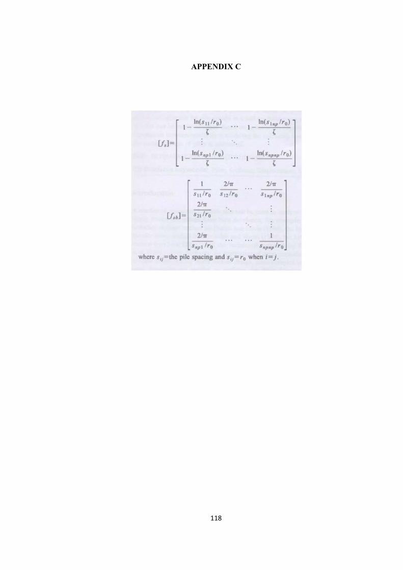
118
APPENDIX C
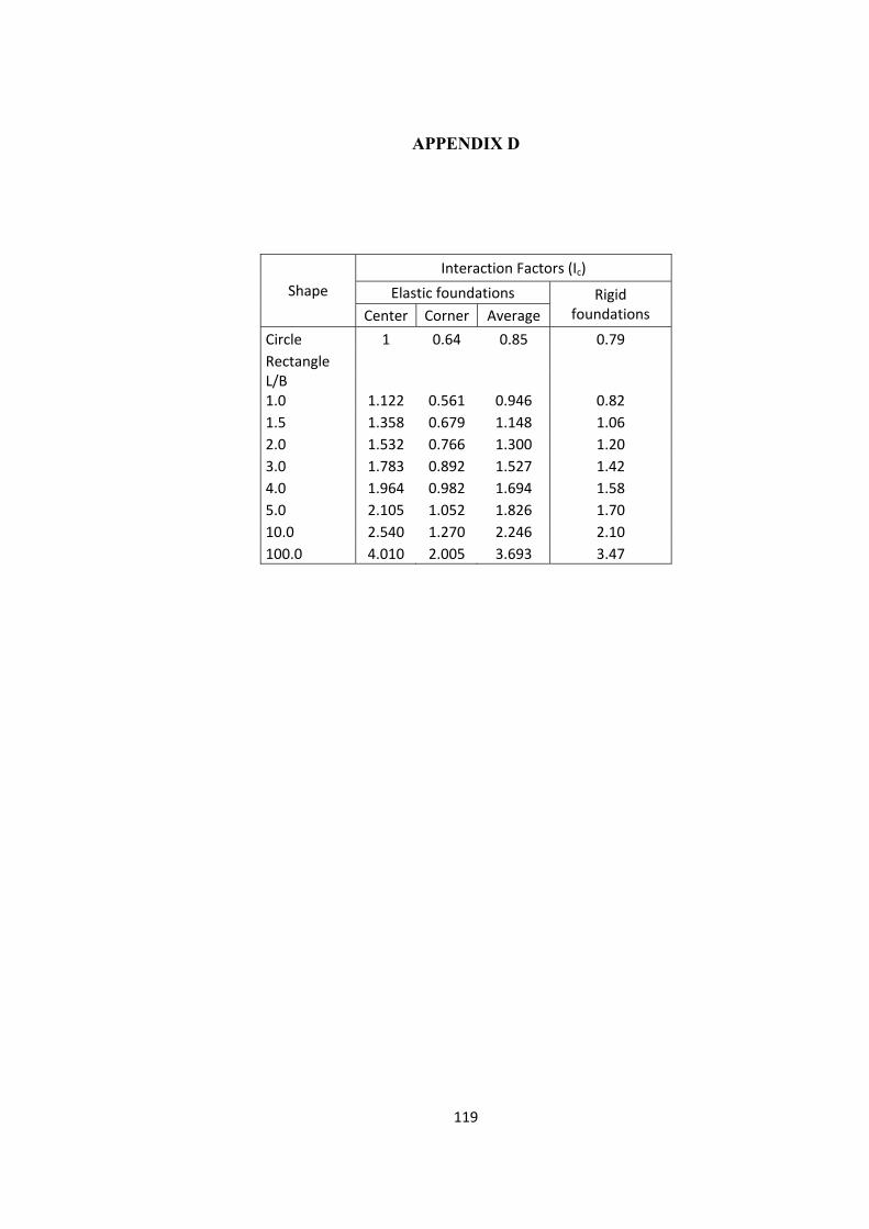
119
APPENDIX D
Shape Interaction Factors (Ic)
Elastic foundations Rigid foundations Center Corner Average
Circle 1 0.64 0.85 0.79 Rectangle L/B 1.0 1.122 0.561 0.946 0.82 1.5 1.358 0.679 1.148 1.06 2.0 1.532 0.766 1.300 1.20 3.0 1.783 0.892 1.527 1.42 4.0 1.964 0.982 1.694 1.58 5.0 2.105 1.052 1.826 1.70 10.0 2.540 1.270 2.246 2.10 100.0 4.010 2.005 3.693 3.47