bericht des instituts für aerodynamik und …bericht des instituts für aerodynamik und...
TRANSCRIPT

Bericht des Instituts für Aerodynamik und Strömungstechnik Report of the Institute of Aerodynamics and Flow Technology
Herausgeber: Deutsches Zentrum für Luft- und Raumfahrt e.V. Institute of Aerodynamics and Flow Technology (AS) Lilienthalplatz 7, D-38108 Braunschweig ISSN 1614-7790 Institute of Aerodynamics and Flow Technology (AS) Institute of Flight Systems (FT) Institute of Composite Structures and Adaptive Systems (FA) Lilienthalplatz 7, D-38108 Braunschweig Institute of Communications and Navigation (KN) Remote Sensing Technology Institute (MF) Oberpfaffenhofen, D- 82234 Weßling Access Level: 1 Braunschweig, December 2007 Head of Institute: Authors: Prof. Dr.-Ing. habil. C.-C. Rossow Dr.-Ing. M.Hepperle (AS) Dipl.-Ing. Alba Ruiz-León (FT) Dipl.-Ing. Hartmut Runge (MF) Dipl.-Ing. M. Horwath (KN) Branch: Configuration Design This Report contains: Branch Leader: 81 Pages Prof. Dr.-Ing. K.-H. Horstmann 73 Pictures 16 Tables 76 References
IB 129-2001/8
Maßnahmen zur Destabilisierung von
Flugzeug-Wirbeln
A. Quast
IB 124-2007/11
HALE Platforms – A Feasibility Study
Dr.-Ing. Martin Hepperle Dipl.-Ing. Alba Ruiz-León Dipl.-Ing. Hartmut Runge Dipl.-Ing. Joachim Horwath

Page 2
Abstract This report describes results of a feasibility study concerning solar powered High Altitude Long Endurance (HALE) Unmanned Aerial Vehicles (UAV). The high altitude concept was examined in order to allow the vehicles to operate above commercial air traffic. The study also produced possible solutions for different flight altitudes and payload requirements. The study was prepared in a cooperation of several DLR institutes, reflecting their interests and know-how. This report combines contributions from several individual authors. The following DLR institutes have been involved in this study:
• Institute of Flight Systems, Braunschweig, • Institute of Aerodynamics and Flow Technology, Braunschweig, • Institute of Communication and Navigation, Oberpfaffenhofen, • Institute of Remote Sensing Technology, Oberpfaffenhofen, and • Institute of Composite Structures and Adaptive Systems, Braunschweig.
A range of feasible solutions for fixed-wing aircraft as well as airships under different requirements (altitude, payload, velocity) have been examined. The following main parameter ranges and features have been considered in order to define the design space:
• payload mass ranging from 5 to 1000 kg, • mission duration between 48 h and infinite , • operating altitude of up to 12 to 30 km, • speed from static to 50 m/s, and • potential sensor types: optical, IR, SAR, LIDAR, Radar, • autonomous operation.

Page 3
1 Table of Contents Abstract....................................................................................................................... 2 1 Table of Contents................................................................................................ 3 2 Symbols and Abbreviations.................................................................................. 3 3 Summary............................................................................................................. 5 4 Introduction ........................................................................................................ 6 5 Restrictions to the Application of UAVs................................................................ 8 6 Previous Work at DLR ........................................................................................ 10 7 Activities Outside of DLR.................................................................................... 12 8 Applications and Payloads ................................................................................. 14 8.1 General Application Potential for HALE platforms................................................14 8.2 Selection Criteria for DLR-HALE Payload Candidates............................................14 8.3 Applications, Payloads and Users ........................................................................14 9 Environment...................................................................................................... 22 9.1 The Atmosphere.................................................................................................22 9.2 Latitude and Time of the Year.............................................................................26 10 On-Board Systems for Unmanned Aerial Vehicles ............................................... 29 10.1 On-Board Systems ..............................................................................................29 10.2 Ground Systems .................................................................................................31 11 Power Resources for a HALE Platform ................................................................ 32 11.1 Solar cells ...........................................................................................................34 11.2 Fuel Cells............................................................................................................36 11.3 Batteries.............................................................................................................41 11.4 Fuel Cells versus Batteries ...................................................................................42 12 Assessment Procedures...................................................................................... 47 13 Vehicle Concepts............................................................................................... 48 13.1 Fixed Wing Vehicle Concepts ..............................................................................48 13.2 Lighter than Air Vehicles.....................................................................................57 14 Conclusions....................................................................................................... 74 References ................................................................................................................. 76
2 Symbols and Abbreviations Symbol Description Unit DGLR Deutsche Gesellschaft für Luft- und Raumfahrt e.V. [-] DLR Deutsches Zentrum für Luft- und Raumfahrt e.V. [-] ESA European Space Agency [-] EU European Union [-]
NASA National Aeronautics and Space Administration [-] Ma Mach number [-] Re Reynolds number [-] D drag force [N] L lift force [N] V volume [m³]

Page 4
l length [m] d diameter [m]
Ppayload power required to operate payload [W] A/C Aircraft [-]
λ slenderness ratio l/d of airship body [-]
ρsolar specific mass of solar cells [kg/m²]
HALE High Altitude Long Endurance [-] MALE Medium Altitude Long Endurance [-] HASE High Altitude Short Endurance [-] MASE Medium Altitude Short Endurance [-] LE Long Endurance [-] HA High Altitude [-] MA Medium Altitude [-] SE Short Endurance [-] HAP High Altitude Platform [-] UAV Unmanned Aerial Vehicle [-] HTA Heavier Than Air [-] LTA Lighter Than Air [-] FSO Free Space Optics [-] EO Earth Observation [-]
GMES Global Monitoring for Environment and Security [-] RF Radio Frequency [-]
GNSS Global Navigation Satellite System [-] GPS Global Positioning System [-] IR Infrared [-]
WLAN Wireless Local Area Network [-] TCAS Traffic Collision Avoidance Systems [-] SAR Synthetic Aperture Radar [-] INU Inertial Navigation Unit [-] LIDAR Light Detection and Ranging [-] FC Fuel Cell [-]
DMFC Direct-methanol fuel cells. [-] MCFC Molten Carbonate Fuel Cells [-] AFC Alkaline Fuel Cells [-] PAFC Phosphoric Acid Fuel Cells [-] PEMFC Proton Exchange Membrane Fuel Cell [-] RFC Regenerative Fuel Cell [-] SOFC Solid Oxide Fuel Cells [-] SALT Solar Airplane Layout Tool [-] SAMS Solar Airplane Mission Simulation [-] APU Auxiliary Power Unit [-] ASB Air Space Body [-] ATS Air Transport System [-] BWB Blended Wing Body [-]

Page 5
3 Summary Unmanned Aerial Vehicles (UAVs) continue to experience an unprecedented attention for military, civil, and scientific applications. They are an important area for aerospace research and industrial applications. UAVs have been used in reconnaissance and intelligence-gathering roles since the 1950s, and more challenging roles are envisioned in military applications as well as in civil applications. While many military systems already fly operationally, there are presently still various unresolved technical and procedural challenges like in the areas of certification, reliability, and flight in controlled airspace. Commercial applications additionally suffer under unclear and partially still unknown cost and performance analyses as well as from the lack of large numbers of potential customers and users. On the other side, an increasing number of new technologies, miniaturization and maturing technical solutions offer the possibility of a breakthrough in the application of UAV vehicles. However, to materialize these developments, a careful balance of integration, continuous technological developments, certification and qualification efforts, as well as a sound financial analysis of business cases and subsequently of cost benefits has to be performed. The goal of this study is to provide DLR with a reliable résumé of different HALE UAV concepts to be able to decide which option will be the best and more appropriate to focus on. We are focusing on vehicles for civil applications, which can be operated on long duration missions and which produce no emissions. This makes them very attractive to environmentally sensible analysis missions like atmospheric sampling or long term monitoring in environmental and geophysical applications. Other applications include communications and related missions. After deciding which HALE platform has the most interesting applications for DLR and its partners, the objective of future work will be to design and build such a prototype, as well as to develop the best combination of technologies, solar power systems with fuel cells or batteries, applicable for the environment of high altitudes. The present report describes a systematical assessment of technological aspects, systems and sub-systems suitable for an experimental high and long flying UAV system intended for scientific purposes. Examples highlight the advantages, as well as the challenges to generate an assessment and analyses beyond simple multi-parameter cost functions. With the example of energy household / power supply strategies as functional requirement of an UAV system and the related potential technical solution by means of fuel cells or batteries, this study provides many details. In the further part, integration of emerging and novel technologies are presented and discussed. Results of the presented work are parametric preliminary sizing studies which indicate how the required vehicles sizes depend on mission requirements.
Page 6
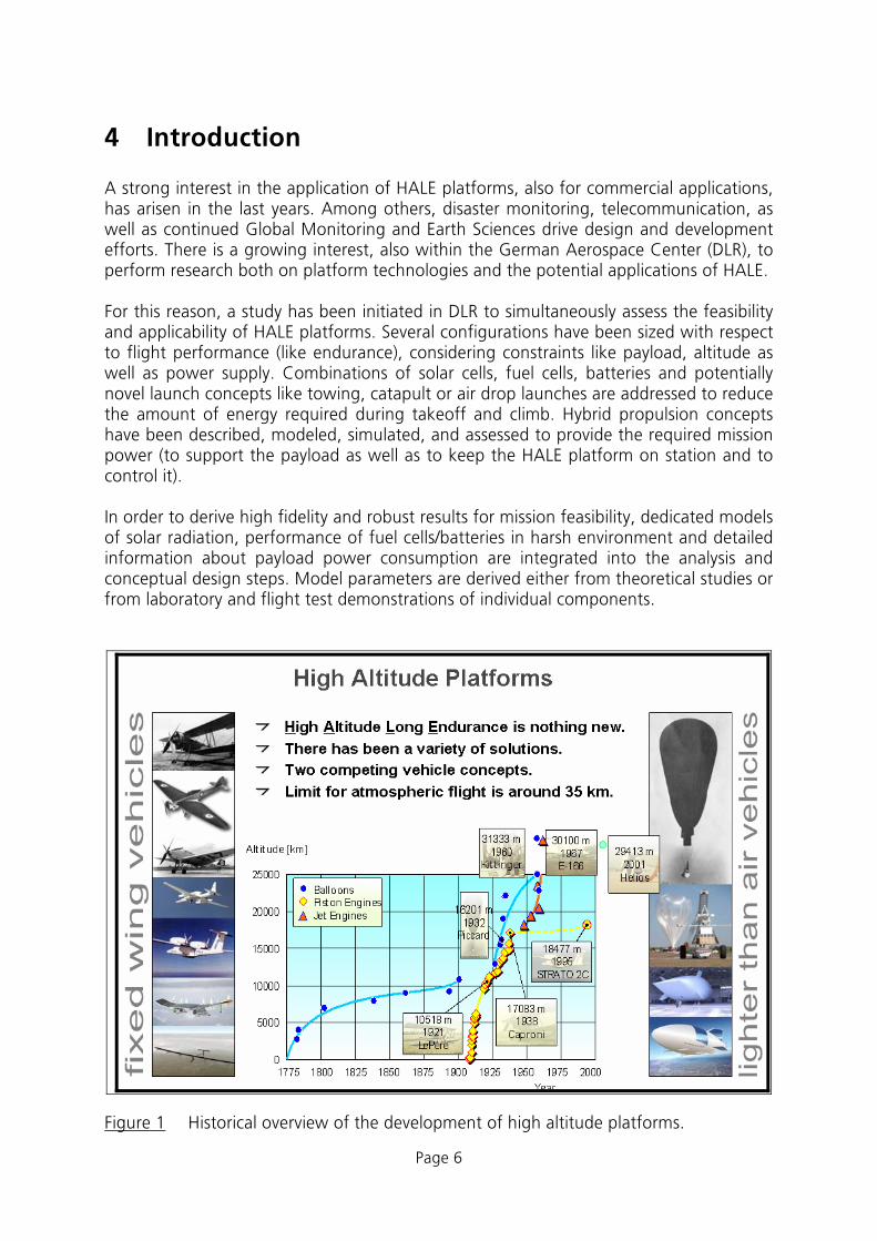
4 Introduction A strong interest in the application of HALE platforms, also for commercial applications, has arisen in the last years. Among others, disaster monitoring, telecommunication, as well as continued Global Monitoring and Earth Sciences drive design and development efforts. There is a growing interest, also within the German Aerospace Center (DLR), to perform research both on platform technologies and the potential applications of HALE. For this reason, a study has been initiated in DLR to simultaneously assess the feasibility and applicability of HALE platforms. Several configurations have been sized with respect to flight performance (like endurance), considering constraints like payload, altitude as well as power supply. Combinations of solar cells, fuel cells, batteries and potentially novel launch concepts like towing, catapult or air drop launches are addressed to reduce the amount of energy required during takeoff and climb. Hybrid propulsion concepts have been described, modeled, simulated, and assessed to provide the required mission power (to support the payload as well as to keep the HALE platform on station and to control it). In order to derive high fidelity and robust results for mission feasibility, dedicated models of solar radiation, performance of fuel cells/batteries in harsh environment and detailed information about payload power consumption are integrated into the analysis and conceptual design steps. Model parameters are derived either from theoretical studies or from laboratory and flight test demonstrations of individual components.
Figure 1 Historical overview of the development of high altitude platforms.

Page 7
An important factor in the future will be the development of “environmentally friendly flying vehicles”. Therefore, we focus on applications with “green” propulsion systems, instead of focusing on purely efficient or purely low cost platforms. Flying with renewable energy sources (which means mainly solar energy) will protect the environment and minimizes interaction of the vehicle with the physical quantities to be measured. Because attractive applications also require long mission times, we also consider long endurance missions, which are challenging when the propulsion system relies on solar energy only. As a result, our HALE platforms will not use combustion engines and it won’t create any contaminations in the form of nitrous or carbon oxides. The vehicles will collect all the required energy from the sun through solar cells (located all over the upper surface of the wing and tail) during the day. Part of this energy will be stored using fuel cells or batteries in order to supply the required energy during night. This green energy will be used by the propellers, which with the help of electric motors will create the thrust for the airframe. DLR as a whole could master the development, design, certification, operation, and exploitation of an experimental, extremely environmentally friendly stratospheric HALE platform. The characteristics of the UAV we propose through this study are the followings:
• purely civil HALE Platform, • pragmatic experimental approach, • extremely environmentally friendly, and • versatile payload facilities.

Page 8
5 Restrictions to the Application of UAVs Since we are referring to Unmanned Aerial Vehicles the locations where such a vehicle can be used are currently somewhat restricted. Some of the main limitations are:
• the vehicle must fit into the Air Traffic System, • the application may be limited due to poor weather conditions, • differences in international regulations make it difficult to fly over borders, • to obtain insurance for the case of a crash may be difficult or costly.
Nevertheless there are regions which reduce some of these limitations. In this study we will consider the possibility to flight in polar regions. To fly in these regions also has the following practical advantages:
• three months daylight in summer , • limited aerial traffic, • no neighborhood present, • reduced risk of damage on the ground in case of crash.
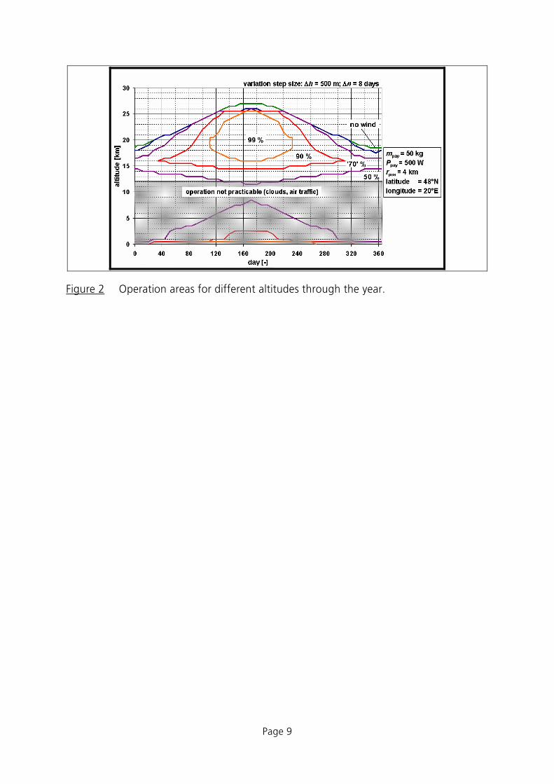
Considering all safety factors makes the feasibility study of this environmentally friendly experimental UAV more complex. Some of the safety & security requirements which must be taken into account are failure monitoring and reconfiguration of systems, collision avoidance, navigation system, flight termination system, recovery systems, lightning protection, anti- / de-icing. In this study different fixed-wing and airship configurations are examined through a parametric study for a range of altitudes between 12 to 30 km. Varying the design altitude and the endurance of a flying platform will have the biggest impact on its size, weight and energy requirements. As the following graph shows for one example configuration, some operation conditions are more suitable to fly regarding the different combinations day of the year and altitude. In this example; we should fly between 15 km and 25 km in summer in order to obtain the best possible flying performance, since below 12 km of altitude we have the presence of clouds and commercial aircraft.
Page 9
Figure 2 Operation areas for different altitudes through the year.

Page 10
6 Previous Work at DLR DLR does not start from zero in this HALE UAV field of research, this approach has a strong background that provides us the information we need to fulfill our feasibility study. This paragraph summarizes experiences from various DLR departments. Besides counting on the knowledge of the senior scientists the topic is also interesting for young engineers as well as students. At DLR, all these are available and needed for the multidisciplinary design work. DLR also has the required design and manufacturing capabilities as well as pilots, operators and end users. DLR has been involved in the development of several high altitude or solar powered aircraft in the past (Figure 3). Areas of applied DLR expertise have been aerodynamics, flight mechanics, aeroelasticity, propulsion. In most cases DLR was involved in single disciplines, not in the overall design, though. Nevertheless this knowledge could be used for the development of new HALE UAV platforms.
Figure 3 High altitude or solar powered prototypes with DLR involvement.
In case of the SOLITAIR project a flying scaled prototype has been developed completely in DLR and flown successfully at low altitudes.

Page 11
Figure 4 The Solitair I demonstrator.

Page 12
7 Activities Outside of DLR The most outstanding prototypes on development nowadays are Mercator (QinetiQ) and Solar Impulse (Swiss Federal Institute of Technology, Bertrand Piccard). A lot of practical experience was also collected by NASA with the flying series culminating in the Helios prototype (AeroVironment) which had been demonstrated in 2003.
Mercator The Mercator is a solar-electric UAV developed to carry valuable observation sensors for such purposes as flood management, disaster relief, fire spotting, and environmental & agricultural monitoring. The high altitude long endurance unmanned aerial vehicle is designed to fly at 60,000 feet for several months at a time, providing a highly accurate and low cost alternative to expensive satellite and manned aircraft surveillance.
Helios The Helios prototype was a unique electrically powered experimental lightweight flying wing developed by AeroVironment, Inc., under NASA's Environmental Research Aircraft and Sensor Technology (ERAST) program. Using energy derived from the sun by day and from fuel cells at night, the Helios Prototype was designed as the forerunner of high-altitude unmanned aerial vehicles that could fly on ultra-long duration environmental science or telecommunications relay missions lasting for weeks or months without using consumable fuels or emitting airborne pollutants.
Solar Impulse Besides the Helios, the Solar Impulse is probably the most realistic design. Although it is a manned vehicle (which imposes many more challenges), its technology is close to what would be required for a fixed wing UAV having a payload of about 250 kg. The aircraft aims at circumnavigating the earth by exploiting solar energy. The solar-powered aircraft needs a huge wing of 80 m span covered with solar cells to fly at 10 km altitude non-stop powered by propeller engines located along the wing. This prototype will carry the necessary buffer batteries to support flying through the night. ESA's Technology Transfer Programme assist the adventurer Bertrand Piccard's flight around the world in a single-pilot solar-powered aircraft, as the ultimate demonstration of the potential for pollution-free flight. A demonstrator aircraft is currently (2007) under development and may fly in 2008.

Page 13
Figure 5 Recent projects outside of DLR.

Page 14
8 Applications and Payloads
8.1 General Application Potential for HALE platforms There are a number of possible areas of application for High Altitude Long Endurance Platforms . (HALE or HAPs) combine advantages of satellite- and terrestrial/airborne infrastructure. This includes for instance short deployment time, a geographical coverage of hundreds of kilometers, easy equipment upgrade etc.
● Telecommunication applications o Next generation mobile communication services (3G)
● Security
o Border/coastline control o Traffic monitoring and control o Civil control and monitoring missions
● Remote sensing
o Pipline Monitoring o Fire prevention monitoring and management o Earth observation missions
8.2 Selection Criteria for DLR-HALE Payload Candidates Beside the general applications and possible payloads of HAPs, several DLR relevant applications and payloads have been identified. The selection criterion is based on
• Scientific relevance and innovation (no commercial solution available) • Relevant for customers (gathered data…) • Possibility of prototype development (public visibility)
8.3 Applications, Payloads and Users
8.3.1 HALE for disaster relief and in Emergency Scenarios Recent natural and man-made disasters showed that there is a need for a rapidly deployable, high capacity communication infrastructure for emergency conditions, when the terrestrial communication infrastructure is damaged, or destroyed. Terrestrial backup stations are not feasible most of the time since they do not provide the coverage and because they are not easy to install (terrain not accessible in case of flood catastrophe or earthquakes, no backhaul network access…). High Altitude Platforms (HAP) can be the right answer to this need in case of disasters. Figure 6 shows the usage of HAP in case of emergency.

Page 15
Figure 6 Emergency scenario for HAP after a disaster .
HAPs operate in the stratosphere, 17-22 km above the ground. This position offers a significant link budget advantage compared to satellites, and a much wider area of coverage than terrestrial communication networks, furthermore due to the high elevation angles, shadowing e.g. from buildings is reduced compared to terrestrial networks. These HAPs are able to serve a large number of users with less communication infrastructure than required by a terrestrial network. This capacity increase is possible by using advanced communication payload concepts for HAPs e.g. multibeam antennas which can cope with the movement and station keeping characteristics of HAPs. HAPs have the advantage of rapid deployment shortly after the disaster, and can bridge the gap until the terrestrial infrastructure is available again. After deploying the HAP above the disaster area, it can provide a communication infrastructure, with the onboard communication payload, which can be e.g. GSM, UMTS or TETRA base station. With the help of the onboard base stations, the destroyed terrestrial communication infrastructure can be easily, rapidly substituted in a relatively cheap way, even in areas, where the portable terrestrial base stations cannot be operated. As Figure 6 shows, the communication can be relayed through satellites, if the other end of the communication channel is out of the coverage area of the HAP, or the end users can directly contact each other through the HAP. This represents the natural extension of concepts already investigated in other projects, such as WISECOM (www.wisecom-fp6.eu) where the different wireless technologies are provided by means of a terrestrial unit. Figure 7 shows the key concepts overview of the WISECOM project, which is coordinated by DLR. If a HAP is available the base stations can be located in the HAP payload. So Figure 7 could be interpreted as the onboard communication payload on a HAP, which can support many communication standards, and contains different base stations: GSM, UMTS, TETRA, WiFi, WiMAX etc.
Transmission of TETRA (TErrestrial Trunked RAdio ) t
Government/organizations with safety missions

Page 16
Figure 7 Overview of the communication payload onboard HAP.
8.3.2 HALE Navigation System Services of Global Navigation Satellite Systems (GNSS) like GPS, GLONASS and the forthcoming GALILEO system have a lot of applications. A similar local system using HAPs would gain from a very high Signal to Noise Ratio (SNR) at the receiver and would allow local real time very high precision services. The case for highly accurate attitude and position determination of a HALE platform is twofold: Firstly, several other missions, such as earth observation require the knowledge of the actual position and attitude of the HALE platform. Secondly, a constellation of HALEs would allow achieving terrestrial navigation in covered areas with an otherwise impossible combination of accuracy and dynamic of position and attitude determination.
TetrManage
BGAN DV -RCManage
GSM UMT
Manage
BGAN DV -RC
Mode
WiFiWiMa
Manage
DirecConnection
(ISDN, Bluetooth
Gateway Functions
(to be detailed)
Standard Equipment HAP Payload Supporting
Functions

Page 17
Figure 8 High precision navigation of HALE and surface vehicles. The relay functionality of the HALE allows achieving significantly higher signal-to-noise ratios at ground receivers than with direct reception of satellite signals.
Three effects lead to the expected improvements in terms of dynamics and accuracy of this system: Firstly, advanced sequential Bayesian algorithms are used to combine the measurements form the GNSS and INS sensors with the a priori knowledge of the HALEs dynamical behavior and, eventually, the control command. This results in very accurate determination of the HALE’s motion. Secondly, due to the proximity (compared to a GNSS-satellite in MEO-Orbit) of the HALE to the ground receiver the signals transmitted from the HALE are subject to far less free-space attenuation. This results in a strongly increased signal-to-noise ratio which in turn results in much shorter integration intervals at the ground receiver. Thirdly, the signal transmitted from the HALE is not subject to ionospheric disturbances, usually a source of error for navigation. Recommendation: Based on these considerations we propose to investigate the feasibility of a HALE navigation system. The payload would involve equipment for GNSS (GPS and Galileo) reception (including antennas), Inertial navigation equipment, onboard processing, accurate timing instrumentation and signal generation and transmission equipment (including antennas).
8.3.3 HALE for Spectral Geo Mapping,
1.) Position and attitude determination of HALE platforms
2.) Transmission of navigation signal

Page 18
Space-based and airborne observation of the earth has led to a deep understanding of our planet. This understanding has proved to be invaluable to protect and enhance our health, safety and welfare. We use this knowledge to find new resources for economical welfare as well as to protect our environment. Sensing the earth’s surface with detectors sensible in or close to the visible spectrum helps to find scarce resources such as water, oil or gas. Furthermore, various forms of RADAR and Synthetic Aperture Radar are used to enhance our capability of detecting substances and structures. However, sensing for the availability and usage of one of the scarcest and most thought resources, namely electromagnetic spectrum usable for terrestrial radio communication and navigation has not been performed from an airborne or space-based platform, so far. Additionally, wireless communication and navigation often performs a life-critical function, such as air traffic management systems. It is therefore important to detect possible interference to such systems, whether intentional and unintentional.
Figure 9 Simulated propagation of electromagnetic signal within an urban environment. Currently, no suitable tool for actual large scale spectral geo-mapping exists.
The usage of electromagnetic spectrum may vary both over spatial location and a periods of 24 hours and/or 7 days. Ideally, observations of electromagnetic emissions should be performed over a period of at least 7 days in combination with a spatial mobility of the platform. That is why a HAP platform is ideal for such a spectral GEO mapping payload. The observations would involve means to sense, store and downlink electromagnetic signals in arbitrarily definable frequency ranges and allow a spatial mapping of the terrestrial source or reflector on the way towards the observation platform. Recommendation:

Page 19
Based on these considerations we propose to investigate the feasibility of an observation system based on a High Altitude Long Endurance (HALE) platform that carries antennas, signal processing equipment, storage media, equipment for location and attitude determination as well as communication equipment for command and control as well as downlinking of measurement data. Several technical and system engineering issues have to be investigated in order to define a payload for the intended mission. In order to achieve spatial referencing capability, a steerable antenna, either mechanically or electronically, such as a two dimensional antenna array is necessary. This issue also influences the size (surface area) and speed of the HALE system.
8.3.4 Broadband communication payload Real-time high-bitrate data links for onboard sensors are becoming more and more essential. Recent years have seen an immense increase in the capability of earth observation (EO) sensors (Ref. to Hartmut’s part). State-of-the-art payloads like high resolution optical or infrared cameras and SAR systems produce data at a speed of gigabits per second. This is why the conventional RF-downlink is suffering from shortness of throughput. The classical limited to some hundred Mbps.
High bitrate optical communication payload High data rates in the range of Gbit/s are the highest motivation to use Free-Space Optics (FSO) systems. However, low terminal size and weight, small aperture sizes and low power consumption are clear advantages to use this technology for HAP systems. The main advantages for optical communication links onboard HAPs are:
• Low power consumption • Low terminal weight • Highest data rates • No interference with mm-wave systems • No regulatory issues • Tap proof operation
There are several challenges for FSO systems onboard HAPs in order to get highest system performance. The transmission beam has to be tracked precisely and platform vibration and station keeping maneuvers have to be compensated. Advanced transmission schemes have to be developed to take atmospheric effects into account. A first successful experimental downlink from a stratospheric balloon testbed has already been demonstrated by DLR-IKN in the frame of the CAPANINA project. A data rate of 1.25 Gbit/s has been transmitted to a ground station over a range of 64 km. An optical link to a ground station within the line of sight would be the first application. Since thick clouds lead to high attenuation and can therefore prevent optical communication, such systems will be operated in diversity with microwave backup systems. When the optical link is available, the microvawe link can be switched off and the highest data transmission rates of the link system can be achieved. Future systems with several HAPs could feature optical inter platform links which do not suffer form attenuation effects in clouds since they operate well above the cloud layer

Page 20
(Figure 38). For global operation the HAP payload data cold be uplinked to a satellite system. For the downlink to a ground station cloud cover diversity will be used.
Figure 10 Possible global HALE scenario with high-bitrate optical backhaul links using satellites.
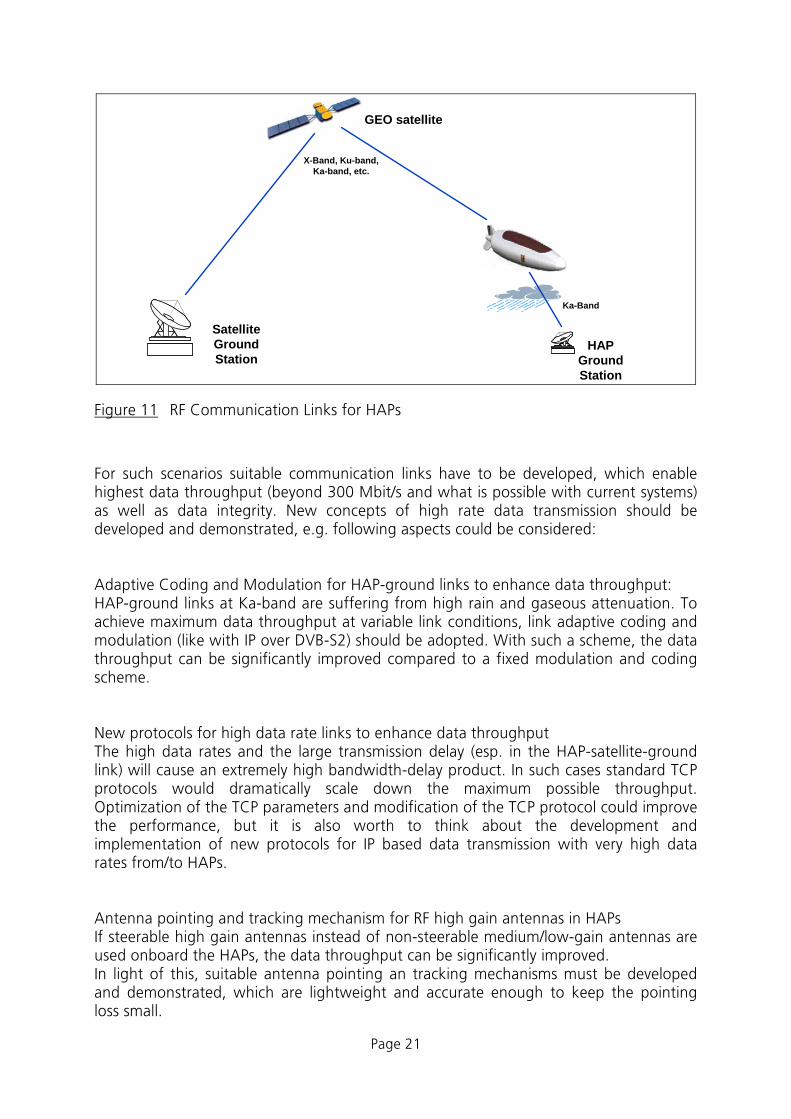
RF Communication from/to stratospheric HAPs: Advanced Concepts for High Data Rate Microwave communication payload If a HAP ground station is in the coverage area of the HAP, the data may be directly transmitted to this ground station. Special RF frequencies have been reserved for such communication links, e.g. in Ka-band. It is also reasonable to transmit the data via HAP-satellite-ground links, because this allows operating the HAP worldwide, i.e. in the coverage area of the communication satellite. High data rates may also be necessary for the feeder links to the HAP and for user links from HAP to ground, e.g. to distribute maps or other information with high data volume.
Page 21
GEO satellite
HAP Ground Station
Satellite Ground Station
Ka-Band
X-Band, Ku-band, Ka-band, etc.
Figure 11 RF Communication Links for HAPs
For such scenarios suitable communication links have to be developed, which enable highest data throughput (beyond 300 Mbit/s and what is possible with current systems) as well as data integrity. New concepts of high rate data transmission should be developed and demonstrated, e.g. following aspects could be considered: Adaptive Coding and Modulation for HAP-ground links to enhance data throughput: HAP-ground links at Ka-band are suffering from high rain and gaseous attenuation. To achieve maximum data throughput at variable link conditions, link adaptive coding and modulation (like with IP over DVB-S2) should be adopted. With such a scheme, the data throughput can be significantly improved compared to a fixed modulation and coding scheme. New protocols for high data rate links to enhance data throughput The high data rates and the large transmission delay (esp. in the HAP-satellite-ground link) will cause an extremely high bandwidth-delay product. In such cases standard TCP protocols would dramatically scale down the maximum possible throughput. Optimization of the TCP parameters and modification of the TCP protocol could improve the performance, but it is also worth to think about the development and implementation of new protocols for IP based data transmission with very high data rates from/to HAPs. Antenna pointing and tracking mechanism for RF high gain antennas in HAPs If steerable high gain antennas instead of non-steerable medium/low-gain antennas are used onboard the HAPs, the data throughput can be significantly improved. In light of this, suitable antenna pointing an tracking mechanisms must be developed and demonstrated, which are lightweight and accurate enough to keep the pointing loss small.

Page 22
9 Environment High altitude platforms operate under extreme atmospheric conditions. These comprise low ambient pressure and temperature, temporarily high wind speeds as well as increased radiation. In order to reach the target altitude regions of high wind speeds must be crossed.
9.1 The Atmosphere The atmosphere of the earth is divided into layers which show different temperature gradients. Aerial vehicles which require a minimum density of the surrounding air to generate aerodynamic or hydrodynamic lift are restricted to operation in the lower layers of the atmosphere, the Troposphere (H = 0…11 km) and the Stratosphere (H = 11…47 km). Most of the commercial air traffic takes place at latitudes between 9 and 12 km. Therefore high altitude platforms try to avoid this air space and the interaction with the air traffic control systems. Another reason to fly at altitudes above 12 km is that the wind profiles show a distinct minimum in the Stratosphere, which minimizes power requirements for station keeping.
Figure 12 Variation of atmospheric properties with altitude.

Page 23
9.1.1 Temperature at Altitude According to the standard atmosphere, the temperature at altitudes between 10 to 24 km is about 215 K (-60°C). These conditions correspond to typical operating conditions for commercial aircraft. These temperatures make systems to control the thermal environment inside the vehicle and its payload necessary. All components, including the vehicle structure must be tested and qualified for operation under these conditions. It may be necessary to provide power for heating certain components. Low temperatures and humidity can lead to icing of vehicles. Icing increases weight, lift and drag. At high altitude humidity is extremely low icing is of no concern for a HALE. Only during climb and descend icing conditions must be avoided by flight planning or the vehicle must be equipped accordingly.
9.1.2 Pressure at Altitude The ambient pressure depends strongly on altitude. At the altitudes of interest, the pressure is reduced to about 1/10 of the pressure at sea level. The reduced pressure is directly related to the density of the air.
9.1.3 Density at Altitude Due to the reduction of pressure with altitude the density is reduced as well. This means that for given wing loading and lift coefficient of a fixed wing vehicle the flight speed
must increase with altitude (0
~v ρρ ). While the actual drag force is not affected, the
required power increases linearly with altitude. For LTA vehicles the reduced density means that larger vehicles are required to reach high altitudes.
9.1.4 Payload Reduction with Altitude For a given vehicle, the possible payload mass is reduced with the altitude. For a given power source (engine) payload mass can be traded against the power consumption of the payload (e.g. sensors). The following graph shows an example for a HALE aircraft (total mass 270 kg and 42 m wing span). Depending on altitude a maximum payload mass and a maximum power available for the payload bound the range inside which payload mass can be traded versus power consumption of the payload.
0
1000
2000
3000
4000
0 50 100 150 200
Payload Mass [Kg]
Payl
oad
Pow
er [W
]
15 km16 km
Figure 13 Payload possibilities for two different altitudes.

Page 24
9.1.5 Wind Speeds at Altitude The wind speeds in the atmosphere vary with altitude, location and time of the year. According to literature [3], [4], the wind speed profile versus altitude shows a minimum around H = 20 km. Therefore flight altitudes between 18 and 22 km are to be preferred to minimize energy consumption for propulsion. In the northern hemisphere low wind speeds of about 5 to 15 m/s occur during summer time, while the wind speed increases to 10 to 40 m/s during winter time. The velocity varies approximately +/- 10 m/s around these mean values. In order to maintain at least zero ground speed against the wind under these conditions, a HALE vehicle must be able to have enough power to fly at air speeds of at least 35 m/s.
0
5
1 0
1 5
2 0
2 5
3 0
3 5
0 5 1 0 1 5 2 0 2 5 3 0 3 5 4 0 4 5Wind Speed (m/s)
Altit
ude
(km
)
0
5
1 0
1 5
2 0
2 5
3 0
3 5
0 1 0 2 0 3 0 4 0 5 0 6 0 7 0 8 0Wind Speed (m/s)
Alti
tude
(km
)
SummerAutumnWinter
Cape Kennedy, FL, USA
Den Helder, NLAverage / YearMaximum/ Year
5 0 6 0 7 0 8 0
Spring
SummerAutumnWinter
Spokane, WA, USA
Den Helder, NLAverage / YearMaximum/ Year
Spring
Figure 14 Typical profiles of average wind speed versus altitude ([4] and [5]).
The high speed regions between 8 and 12 km altitude are also called “Jet Streams”. They can be locally extending over some thousands of kilometers in length and a few hundred kilometers in width. There are two main streams: the Sub-Tropical Jet Stream found at latitudes between 20° and 50° and a Polar Jet Stream found between 30° and 70°. These two main jet streams flow from west to east (westerly jets) in both northern hemisphere and southern

Page 25
hemisphere. In summer, easterly jets such as the Equatorial Easterly Jet (between 10°N and 20°N) can form in tropical regions.
Figure 15 Jet streams at altitude.
The wind speeds vary according to the temperature gradient, averaging 55 km/h in summer and 120 km/h in winter, although speeds of 550 km/h are also known. A HALE UAV can exploit jet streams to change its position provided that accurate information about the current status of jet streams is available. On the other hand the high speeds can also lead also to high shear wind and gust components which must be accounted for in the structural design of the vehicle.
9.1.6 Oxygen at Altitude The atmosphere is composed of 78 % nitrogen, 21 % oxygen and 1% of other gases. Regarding to a HALE platform the amount of oxygen gas will decrease with the pressure reduction at altitude. This would represent a problem if the vehicle is designed to fly with fuel cells. Since the FC operates with oxygen, we will have to introduce an oxygen tank and/or an electrolyzer, elements that increase the complexity of our system. On the other hand if the aircraft is equipped only with batteries and solar cells, the lower levels of oxygen would not present a problem.
9.1.7 Solar Radiation at Altitude The solar radiation at altitude can vary, depending on location and time of the year. This variation is due to the attenuation factor of the lower layers of the atmosphere and not because the proximity to the sun, since this distance is so large that a few kilometers up or down will not make any big difference. In figure 16 the solar radiation is represented for 3 different latitudes and 3 different altitudes. The twelve lines in each graph represent the incident radiation on a average day of each month of the year. It can be seen that the peak radiation varies by about 30-40% when the altitude is increased from sea level to 25 km. Note that the variation over the day is vanishing when the latitude is shifted towards polar regions, even with reduced peak values still producing a reasonable mean value over the day.

Page 26
Figure 16 Variation of solar radiation with latitude and altitude.
9.2 Latitude and Time of the Year
9.2.1 Latitude One of the most important factors for solar powered platforms is the operating latitude. The hours of daylight, direction of the solar rays relative to the solar panels affect the total solar energy collected and so the power available for the platform. Therefore a careful optimization of the vehicle and the flight planning is required. Generally the best latitudes for fixed wing aircraft with mostly horizontally aligned solar cells are
• around the Capricorn and Cancer Tropics to obtain perpendicular rays from the sun on the solar panels located at the aircraft, and
• at polar regions with their long periods of sun light, 3 months in summer, that compensate for the low elevation angle of the solar rays.

Page 27
9.2.2 Time of the Year Taking also into account the different seasons of the year, were the elevation of the solar ray varies giving us different combinations of intensity and light hours we have obtained the payload possibilities shown in figure 17. Note that these results are for a platform with horizontally aligned solar cells.
20
25
30
35
40
45
50
0 60 120 180 240 300 360
Day of Year
Latit
ude,
deg
. Nor
th
0 Kg50 Kg100 Kg150 Kg200 Kg
Figure 17 Payload possibilities versus latitude for different season periods and a given altitude.
The power obtained from the cells increases when the Tropic Areas are approached and while flying in the summer period where the intensity of the solar radiation is higher and the daylight hours are longer. The figure shows that for a given altitude a fixed wing platform would be carry the largest payload during the summer period at the Tropic of Cancer and Capricorn areas. Merging all data obtained in the previous sections we conclude that flying in summer period and at the latitudes (36° and 90°) are the best solutions to obtain the best solar efficiency for fixed wing aircraft.

Page 28
Figure 18 Best latitude and seasonality combination.

Page 29
10 On-Board Systems for Unmanned Aerial Vehicles
10.1 On-Board Systems The flight control and guidance systems that are placed in the aircraft are called on-board systems. The sensors are those elements used to measure and collect data. The sensor data is the input data of the control elements, which based on this information generates the flight control commands by means of the guidance laws. The process ends with the movement of elevators, ailerons and rudders thanks to the actuators.
Figure 19 Block diagram of the on-board flight control and guidance systems.
10.1.1 Sensors It is necessary to collect some data in order to control the aircraft, as for example position, altitude, ground velocity, air speed, acceleration etc.. Usually the flight control sensors are designed with redundancy to ensure the accuracy of the measured data.
• GPS receiver & Antenna With a GPS receiver we can measure ground velocity, latitude, and longitude. With this data and the data obtained from other sensors the position and the ground speed are fused. A GPS antenna is necessary to receive the satellite signals.
• Magnetometer The magnetometer measures the magnitude and direction of the Earth’s magnetic field and in this way calculates the heading of the aircraft.
• Gyroscope A gyro provides the angular rates of the UAV: Yaw, Pitch and Roll rate and once integrated also the Euler angles.

Page 30
• G-Sensor A G-sensor is a device to measure the acceleration of the aircraft. Normally the value of the acceleration is given for each of the three axes (Ax, Ay and Az). It is very usual to have accelerometers (G-Sensors) and gyroscopes in a closed system called Inertial Measurement Unit (IMU).
• Air Data Sensor This sensor measures both static and dynamic pressures in order to determine the airspeed and the pressure altitude of the UAV.
• Integrated Sensor Suite There are suites that have all the sensors described before (gyros, magnetometer, GPS receiver, accelerometers and air data pressure transducers) integrated into a single unit. In table 1 some characteristics of the different sensors and an Integrated Sensor Suite are shown.
Table 1 Sensor and integrated sensor suite characteristics.
Having an Integrated Sensor Suite would be a better option than having all the sensors individually due to weight constraints. Furthermore, in this way the connections between the different sensors are simpler and encapsulated, which means more safety and reliability.
• Collision Avoidance/Transponder: A collision avoidance system allows the UAV to detect other aircraft and maneuver around them. This system involves two subsystems: one sensor to detect the intruding aircraft and the software to predict which course of action should be taken to avoid the aircraft. If we have a cooperative sensor for collision avoidance, the aircraft will have transponders or data links notifying other aircraft of its position. In the other aircraft does not share its position (non-cooperative detection), it can also be detected using a radar or optical sensors.

Page 31
10.1.2 Control Computers for FCS The computer is designed to take the data of the sensors and execute the guidance laws. Normally it is also used for communication management. The picture below illustrates the data needed for the guidance of the aircraft and the sensors that are necessary to collect this data. An integrated navigation algorithm is created based in the optimum choice of navigation data from the different sensors.
Figure 20 Sensors and Flight Control Computer Actuators.
Some actuators are needed to move the elevator, aileron, rudder, etc. as well as the throttle actuator or the actuator engage device.
10.2 Ground Systems The ground systems are as important as the on-board flight control systems, because from the ground we are able to remotely control the UAV. In this way, antennas for receiving and sending information to the UAV are needed, as well as a computer and the appropriate software for monitoring all the data.
FLIGHT CONTROL
COMPUTER
SENSORS

Page 32
11 Power Resources for a HALE Platform Regarding the power sources needed in a HALE UAV platform, either fixed-wing or airship configuration, prepared for long endurance flights, we will need to solve the problem between regenerative systems and the extra weight they produce. In the following steps we have considered the possibilities for day and night flight as shown in figure 21.
Figure 21 Possible power resources for the different time of day.
One major question is whether to use fuel cells and/or batteries besides the solar cells to provide power during the night hours? The choice between both alternatives depends first of all on the foreseen payload and on the required flight altitude and endurance of the mission. It is also a function of the environmental conditions and the time of the year. Depending on these parameters, it will be better to use fuel cell or battery technologies. Besides these technical demands, the price difference between both type of storage media obviously also plays a vital role. At the moment, energy storage in commercially available, highly efficient new batteries is the most economic choice. Below, first the approach used in this selection is described. Then, the different options are defined and their characteristics are briefly discussed. Some extra details on fuel cells and their operation are given too before a comparison is made. Finally, some conclusions are drawn on the most appropriate option for a fixed-wing HALE UAV. The use of new propulsion architectures entails a resizing of the vehicle structure to accommodate the new elements and support the new volumes and weights. The complete UAV and its foreseen mission therefore need to be considered in the selection of the secondary power storage system. The following graph shows the three inter-connected layers that will determine our selection: analysis, design, and decision-support.

Page 33
Figure 22 Vision of Novel Design and Decision-Support Environment [37]
As mentioned before, the mission plays an important role in the choice. For fixed wing aircraft, a typical one-day flight profile assumed here for the long endurance phase of the mission is presented in figure 23. This daily profile will be repeated for several consecutive times to complete the whole mission. A power-off glide segment is used to reduce the amount of power required during the night hours. The duration of this glide period depends on the mission requirements, the onboard payload and the foreseen power resources. The adoption of a power-off glide segment reduces the size of the power storage medium, as only the payload needs to be powered during this part of the night. The actual or achievable reduction in power strongly depends on the day length and the solar intensity.
Figure 23 Power operation during the 24h of the day. Gliding and climbing possible procedure to reduce the size of the power storage media initially required.

Page 34
In terms of power it would be beneficial to begin the glide segment with the sunset (defined as the moment where there is not enough sun power anymore for the propulsion of the UAV) and the climb segment around midday. In this way, the power and light levels would be used to the maximum extent. The glide and climb segments are shown with straight lines in the graph. In reality they are however not linear in time as the density of the air, the power required, the energy storage, wind conditions and the angle of attack of the UAV change during descent and ascent. As the storage system needs to provide the nighttime power, the power required by the payload will be the main driver for the size of this storage system and thus also to some extent of the solar cells and the wing span. Obviously the aerodynamic characteristics of the UAV also play an important role but for the current selection, the weight of the storage medium is the most important factor. Air ship configurations have the advantage, that they can maintain their altitude at night without falling back to energy stored during daytime. They only need power to operate the payload, their systems but also power for propulsion, depending on wind speed and mission requirements.
11.1 Solar cells
Solar cells are necessary to provide energy over the day and to fulfill the energy requirements to charge the batteries and/or fuel cells for night operation. Based on their mechanical properties, two main types can be distinguished: flexible and rigid cells.
Flexible Solar Panels The most important characteristics of flexible solar cells are that they can conform to different surfaces. They are also generally lightweight and low-cost, but the cells commercially available today have low efficiencies (amorphous silicon thin-film: ~5%). New technologies like CIGS thin-film solar cells have demonstrated efficiencies about 14%, but they are still in laboratory stage.
Rigid Solar Panels Rigid solar cells are a very mature technology. Two main rigid solar cell types can be distinguished: silicon solar cells and gallium arsenide solar cells. Silicon solar cells are the most commonly used solar cells and can be manufactured in different ways: monocrystalline, polycrystalline or ribbon. Silicon solar cells have efficiencies of about 15% (W/m2), however they have very low W/kg ratios. On the other hand, gallium arsenide solar cells (GaAs) are used for space applications. They have very high efficiencies (~30%) with low weights, but they are also some of the most expensive cells on the market.

Page 35
11.1.1 Comparison of Flexible and Rigid Solar Panels
Figure 24 Rigid and flexible solar panels comparison.
The two possibilities (rigid and flexible solar cells) are shown in table 2.
Table 2 The best rigid and flexible solar panels in the market.

Page 36
11.2 Fuel Cells
11.2.1 Fuel Cell Definition A fuel cell is an electrochemical energy conversion device that combines hydrogen and oxygen to produce electricity, with water and heat as byproducts. Fuel cells can operate continuously as long as fuel is supplied in contrast with the inherently discontinuous operation of a battery. Since the conversion of the fuel (e.g. hydrogen) to energy takes place via an electrochemical process, instead of through combustion, fuel cells are clean, quiet and highly efficient by nature. The next table shows typical weights of a fuel cell energy storage system for a HALE mission of 14 days endurance and 20 km height.
Component Weight (Kg)Fuel 489Power System 195
Table 3 Initial Weight Allocation for vehicle fuel and Power System [38]
11.2.2 Fuel Cell Efficiency A typical single fuel cell “cell” produces between 1 and 12 Watts and its theoretical output voltage is 1,16V. This voltage characterizes the case in which all the energy in the fuel is turned into electricity. However, during real operation this voltage will decrease. The difference between the ideal voltage and the real one translates into the efficiency of the fuel cell. For example if the individual cell is operating at 0,7V it is operating at an approximate efficiency of 60%. This means that 60% of the available energy content of the hydrogen is converted into electrical energy and the remaining 40% turns into heat. To create enough voltage, individual fuel cells are typically combined in series and parallel circuits into a fuel cell stack. Series wiring increases voltage but not amp/hour capacity. On the other hand, parallel wiring increases capacity but not voltage. The number of cells used to form a fuel cell stack is usually greater than 45. The efficiency of a fuel cell is very dependent on the current through the fuel cell: as a general rule, the more current drawn, the lower the efficiency. High operating efficiencies can be reached at low power levels as it is shown in figure 30, which belongs to a typical PEM fuel cell. The greater the output power or current produced by the fuel cell the lower it’s the operating voltage and efficiency and higher the waste heat. Therefore depending on the operating point means for removing this excess heat must be incorporated into the fuel cell system design. If the fuel cell is not cooled its temperature will rise significantly and damage or complete failure of the fuel cell will occur.

Page 37
Table 4 Voltage & Output Power vs. Current Density for a Typical PEM Cell [39]
It is important to take losses due to production, transportation, and storage into account. Fuel cell vehicles running on compressed hydrogen may have a power-plant-to-wheel efficiency of 22% if the hydrogen is stored as high-pressure gas, and 17% if it is stored as liquid hydrogen. Fuel cells cannot store energy like a battery, but in some applications, they are combined with electrolyzers and storage systems to form an energy storage system. The overall efficiency (electricity to hydrogen and back to electricity) of such plants is between 30 and 50%. While a much cheaper lead-acid battery might return about 90%. The electrolyzer/fuel cell system can store indefinite quantities of hydrogen, and is therefore better suited for long-term storage.
11.2.3 Fuel Cell types For HALE UAVs with endurance in the order of months, the energy needed on board has to be supplied by an inexhaustible renewable energy source like solar panels. However, an additional power storage medium is needed for nighttime operation. Among the different fuel cells types in the market we have selected the PEM FC (Proton Exchange Membrane Fuel Cell) because give us better power density and specific power than the others, as shown in the following table.

Page 38
Table 5 Fuel cells types.
11.2.4 Selection of Fuel Once the fuel cells are selected we need to pick the most appropriate gas with which they will work. From the possible gas / fuel that PEM can work with (natural gas, hydrogen, methanol, diesel, ammonia, biogas and gasoline) we have selected hydrogen because it gives us more power density per weight than the others this characteristic being the most critical for flying a HALE UAV. Besides, this gas is the most appropriate for the environment because does not create residual contaminant gases like CO and CO2. Hydrogen is used in liquid form (LH2) to minimize storage volume.
Figure 25 Gases and fuels possibilities for fuel cell applications [41]
Today, mostly methanol and hydrogen are used as fuels for fuel cells. Methanol is a liquid fuel that has similar properties to gasoline. It is easy to transport and distribute, so methanol may be a likely candidate to power fuel-cell cars. However, for our application liquid hydrogen seems to be more suitable. If we compare methanol and liquid hydrogen power densities, methanol has a higher power density per volume but a lower power density per mass. Considering that mass is a more important aspect for us than the volume, and the big difference in power density per weight between both fuels comparing to the small difference in power density per volume, we choose liquid hydrogen to feed the fuel cells.

Page 39
Table 6 Fuel gasses characteristics.
11.2.5 Hydrogen production A suitable way to produce hydrogen is by electrolysis. Electrolysis separates the elements of water, hydrogen and oxygen, by applying an electrical current. This makes it also possible to produce a closed circuit of hydrogen production, decomposition in a fuel cell and feeding back the produced water into the electrolyzer. Electrolyzers are usually of high conversion efficiency, roughly 70%, with the best commercially available examples approaching 90% efficiency. Adding an electrolyte such as salt improves the conductivity of the water and increases the efficiency of the process. The smallest amount of electricity necessary to electrolyze one mole of water is 65.3Wh and Producing one cubic meter of hydrogen requires or 4.8 kWh of electricity. As a result we conclude that the use of hydrogen is the best efficient solution for our platform storage system but has some negative side effects:
● The high energy required to produce it and later storage at low temperatures. In the case of an electrolyzer on board this energy should be taken from the solar cells what will strongly decrease our vehicle performance.
● The continuous losses due the storage system of this gas in tanks. As hydrogen is a very small molecule, some hydrogen will leak from the tanks.
● The extra weight of the tanks, explained in the next point below.

Page 40
11.2.6 Fuel Tanks To make a fair comparison between the different fuels, however, the tank and fuel supply system weight needs to be included. A big tank weight could offset the advantage of the hydrogen fuel, which can be stored in gaseous or liquid form. Gaseous hydrogen has a very low density which translates in large fuel tanks requirements (higher weight) even for a great storage pressure. Nowadays existing LH2 tanks are however heavier than desired for this HALE application as is shown in the figure below. Although the use of liquid hydrogen as a fuel does add some complexity due to the large thermal difference between storage and engine temperatures, the overall effect on the vehicle is still advantageous.
Figure 26 Fuel capacity and mass fraction for several existing LH2 tanks. Mass fraction defined as ratio of tank dry weight to usable fuel weight [38]
The following table 7 shows different types of fuel tanks operating with different fuels. They are ordered by Wh/kg, which is the most important characteristic for our HALE UAV.
Table 7 Typical available fuel tanks.
As explained in the chapter on the properties of the atmosphere, the partial pressure of oxygen drops with the pressure reduction at altitude. This means that oxygen has to be compressed from the sparse amount available in the atmosphere. Therefore a compressor and an additional oxygen tank have to be introduced. Some of this effort can be reduced when a regenerative fuel cell with an electrolyzer is used.

Page 41
11.2.7 Regenerative Fuel Cells (RCF) For long duration missions regenerative systems are needed. This solution closes the hydrogen circuit with an electrolyzer on board by converting the simple fuel cell system into a regenerative fuel cell. With such a system one could fly almost eternally since this device will produce the hydrogen by itself. The Regenerative Fuel Cell (RFC) is a system that can operate in a closed loop and could serve as the basis of a hydrogen economy operating on renewable energy. It is a dual-function system. This means that they are designed to operate not only as a fuel cell but also in reverse as an electrolyzer. So the electricity can be used to convert the water back into hydrogen and oxygen. If we put together any of the fuel cell types explained before and an electrolyzer we will obtain a RFC. So a RFC is like the combination of a fuel cell and an electrolyzer in a single device.
Figure 27 Closed water circuit with electrolyzer on board.
11.3 Batteries As we have said before the use of FCs is still under development and requires complex systems. While this is an interesting topic for long term research, we have selected the use of storage batteries for a first step towards a practical solar UAV
11.3.1 Battery Systems Batteries consist of electrochemical devices, such as two or more galvanic cells, fuel cells or flow cells, arranged in parallel or series that store chemical energy and make it available in an electrical form. They can be charged electrically to provide a static potential for power or to release an electrical charge when needed. They generally consist of an anode, a cathode, and an electrolyte. The important battery characteristics to take into account are:
• Reduction of performance with the number of cycles, which obviously becomes important for a long endurance mission.
• They are not only limited by their specific power (W/kg) but also by their discharge rate, the amount of power that can be released per time.

Page 42
Batteries are highly developed today, the reason why they present fewer problems and show a low system complexity. The efficiency of a battery depends on discharge rate. Low discharge rates are generally more efficient than higher discharge rates. Table 8 presets a comparison of different currently available battery technologies. Modern Lithium-Polymer designs can have cycle efficiencies of more than 90%. They also have a very high energy density and low specific mass.
Table 8 Available battery technologies.
11.4 Fuel Cells versus Batteries In order to choose regenerative FC or batteries as a storage device some investigations were performed and comparison charts have been produced. In the table below the differences between these two power systems is shown. The FC has the benefit of a constant output voltage versus the variable voltage of the battery during charge or discharge.
Table 9 Comparison of FC versus Batteries.

Page 43
11.4.1 Possible Combinations Through all this power possibilities study to cover day and night hours we could conclude that the different combination possibilities are:
1. Operation with batteries, without fuel cells • lower operation efficiency • “eternal” endurance • heavier system • discontinuous operation of a battery
Figure 28 Operation with batteries, without fuel cells chart.
2. Operation with fuel cells
• for an endurance under 14 days • fulfilled liquid hydrogen (and oxygen tanks for high altitudes) • continuous operation
Figure 29 Operation with fuel cells chart.

Page 44
3. Operation with fuel cells + electrolyzer
• “eternal” endurance • Not required fulfilled hydrogen neither oxygen tanks • continuous operation
Figure 30 Operation with fuel cells and electrolyzer chart.
4. Operation with fuel cells + batteries • Point 2 + redundancy of devices to ensure our mission
Figure 31 Operation with fuel cells and batteries chart.

Page 45
5. Operation with fuel cells + electrolyzer + batteries
• Point 3 + redundancy of devices to ensure our mission
Figure 32 Operation with fuel cells, electrolyzer and batteries chart.
In order to find the best power combinations for the different platform metrics referred before (altitude, endurance) we have created the next table that give us the best solutions for the different missions.
Table 10 Best power combination for different altitude endurance combinations.
Page 46
For a short endurance mission (<14 days) we would either use batteries or fuel cells. We will choose one or another depending on the requirements we have. We have concluded that for a 3 months flight batteries will be the best option. On the other hand, for very long periods of time (>18 months) we will always use fuel cells working together with an electrolyzer with a double closed loop of oxygen and water. Finally, between 6 and 12 months, the aircraft will be equipped with batteries or fuel cells + electrolyzer depending on the application. Batteries will always be the best choice from an economical point of view. However, if our purpose is making a high performance vehicle we will choose fuel cells + batteries. It is also important to mention that fuel cells are more appropriate for higher altitudes as batteries as we will have more demanding flying conditions. Note: A certain minimal battery capacity will always be required for the essential flight control functions, TCAS, FCS up- and downlink etc.. Even though, strictly speaking, the platform is no longer powered exclusively by the solar cell/fuel cell system, the batteries only serve as a backup in case of emergency in order not to jeopardize the HALE. This reserve storage system will be used for safety reasons to avoid a lack of energy on the controls side and so a complete destabilization of the system. The presence of the batteries thus is simply a really nice case of dissimilar redundancy.

Page 47
12 Assessment Procedures The objective of this feasibility study is to assess the feasibility of HALE configurations for different applications of interest for DLR and its partners. In order to perform such an assessment existing simulation models have been used and new models have been developed. With these models a sizing of vehicles for different mission requirements was performed. Some of the resulting fixed wing aircraft have been developed further (mainly smaller vehicles, suitable as a small scale demonstrator). A variety of tools has been used to model and simulate the vehicles and their mission:
● existing tools like SALT and SAMS (which have been developed by Keidel [2]). ● newly developed simple tools like Excel spreadsheets, ● newly developed complex tools using the ModelCenter framework, ● CAD tools like CATIA or Rhinoceros.
The study was based on studying some selected possibilities in a matrix of possible requirements and constraints:
• different platform configurations: fixed wing aircraft and airships, • payload mass from 5 to 1000 kg, • mission duration between 48 h and infinite , • operating altitude of up to 12 to 30 km, • operating speed from static to 50 m/s, and • green energy sources: fuel cells, solar cells, • different operating latitudes (effect of sun elevation and daylight duration).
In figure 33 all possible configurations regarding the propulsion system and design configurations are shown. The possibilities taken into account for this study are marked in green, while the arrows show the propulsion systems considered for each configuration:.
Figure 33 Possible configurations regarding to propulsion system and configurations.

Page 48
13 Vehicle Concepts
13.1 Fixed Wing Vehicle Concepts Fixed-wing aircraft include a large range of aircraft. Depending on the propulsion we can classify the aircraft as gliders, propeller aircraft, jet aircraft, supersonic jet aircraft, rocket-powered aircraft, ramjet aircraft, scramjet aircraft etc.. In this section we will select all the devices necessary for our fixed wing vehicle for a subsequent data calculation and vehicle selection for all altitudes, endurances and payload requirements.
Figure 34 Preliminary fixed wing design.
13.1.1 Electric Motor Type In this section we will select the most adequate motor (component which transforms electrical energy into mechanical thrust) for our fixed wing platform. For a flying vehicle an electric motor is used to drive the propellers that produce thrust. Due to fuel cells and batteries output power is given in DC form; we have chosen a DC electric motor for our vehicle. In addition to this, DC electric motors have an advantage when it comes to driving a propeller: the torque-speed characteristics are easier to control than these of AC motors. However since both AC and DC electric motors could be installed in our platform, a table shows the different motor types we have been studying and their characteristics for a better understanding.

Page 49
Table 11 Different motor types characteristics.
The brushless DC motors are the best option for our platform because they have high torque moments and low weight. The main advantage of using a brushless DC motor is the elimination of the contact brushes. The brushes could wear out and may be subject to arcing at the low density and pressure environment within which the aircraft will be operating. This provides a brushless motor, a longer lifetime, higher efficiency and reliability and reduced noise. Besides, brushless motors are typically 85-90% efficient, whereas DC motors with brushes are typically 75-80% efficient. Besides, electric motors have many advantages over internal combustion engine such as low vibration level, high reliability, and no-pollution emission. These characteristics are very useful in practical operations, especially for civil missions. Finally, brushless motors are the type of motor that has been used in the examples we have based on so it will we adequate for our purpose. The electric motor must be designed together with its controller system to operate at high altitudes and low temperature with the highest efficiency possible. Due to the low density, cooling must be carefully considered.

Page 50
13.1.2 Propellers The propeller is one of the most critical elements of the propulsion system and one of the most highly stressed components on an aircraft. The majority of the power produced and consumed by the aircraft is for the production of thrust (movement). Therefore, the efficiency and performance of the propeller affects directly design of the power system as well as other propulsion components. The propeller is the only part of the propulsion system affected by the loss in air density with altitude. A well-designed propeller can have an efficiency of 80-90% when operating in its best regime. Depending on power, cruise speed and operating altitude, a specific propeller would have to be designed. Figure 35 shows the efficiency versus power for a specific, existing example of a highly efficient propeller.
Figure 35 Efficiency of the propeller for the Antares aircraft [33] versus engine power for different altitudes.

Page 51
13.1.3 Examples of Demonstrator Models In order to study the main effects, some fixed wing vehicles have been conceptually designed, starting with the Solitair, see figure 36.
Figure 36 HALE UAV fixed-wing evolution 2007 [33].
Depending on the application, altitude, endurance, latitude, payload mass, power source, devices, material, structural weight, dimensions, required performance, mission etc. the platform geometries will merge into different shapes. Below different stages of the designed prototypes are presented:
Figure 37 Alba structure designs for fixed wing configurations 2007.

Page 52
Figure 38 Arnaud final designs for fixed wing configurations 2007.
13.1.4 Operation Point After making a parametric study of different fixed-wing configurations for different altitudes through various computer programs we have obtained some feasible solutions. Let’s present one singular case for a better understanding. For a fixed wing vehicle flying at: 45° latitude, summer period (day of the year 210), 40 m of wing span, and at an altitude of 20000 m. See the example below:
Figure 39 Operational point for a given fixed wing vehicle.

Page 53
Here we will give just one example (operational point data base) from all obtained during this study due to space limitations. But here below is shown the table with all the results reached for all possible combinations. For this table results, as said before, have been selected for the fixed wing configuration fitted with solar modules and batteries for a primary data base approach. The results are given for the devices studied in the previous sections.
Figure 40 Final parametric chart for fixed wing vehicles
Thanks to the table above we have all the design data for all applications no matter which altitude, latitude, power source, TOW, speed requirement. While studying the table above we could cite that a longer wing-span is required as the altitude increases (air density decreases), consequently the platform weight will rise. It is a fact that the wing span will have to increase in order to maintain a constant lift. On the other hand as we fly higher we will need higher vehicle speeds to maintain the lift (due to the air density decrease), that consequently will rise our power platform requests and so again the weight.

Page 54
Figure 41 Wing span and takeoff mass versus altitude.
Figure 42 Speed and necessary on power versus altitude.

Page 55
13.1.5 Application at the North Pole The polar regions offer interesting applications for solar powered HALE platforms. Therefore this application has been studied in more detail. In order to obtain the best solar efficiency at different altitudes we have studied three cases of solar panels orientation:
• fix solar arrays at 90° (vertical), • fix solar arrays at the best angle 68.8°, • and movable solar panels as the sun changes position,
As we can see in the table below the best configuration is the one with a moveable solar array, then β�= 68.8° and finally β�= 90°. However, it needs to be noted that in the case of moveable solar arrays, additional devices are needed to move the solar panels. This will lead to a more complex system and a higher platform weight. Therefore, a study should be made to verify if the extra benefit is enough to compensate the penalties resulting from this option.
Figure 43 kW of solar radiation obtained at different attitudes at the best seasonality (3 months endurance) for various configurations of solar arrays.
Page 56
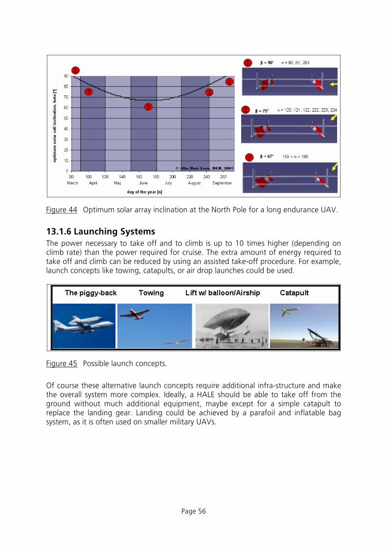
Figure 44 Optimum solar array inclination at the North Pole for a long endurance UAV.
13.1.6 Launching Systems The power necessary to take off and to climb is up to 10 times higher (depending on climb rate) than the power required for cruise. The extra amount of energy required to take off and climb can be reduced by using an assisted take-off procedure. For example, launch concepts like towing, catapults, or air drop launches could be used.
Figure 45 Possible launch concepts.
Of course these alternative launch concepts require additional infra-structure and make the overall system more complex. Ideally, a HALE should be able to take off from the ground without much additional equipment, maybe except for a simple catapult to replace the landing gear. Landing could be achieved by a parafoil and inflatable bag system, as it is often used on smaller military UAVs.

Page 57
13.2 Lighter than Air Vehicles In contrast to heavier than air vehicles balloons and air ships rely mainly on static lift and do not have to create dynamic lift. Hence they do not have to counteract vortex drag (induced drag), which is about 50% of the total drag of a fixed wing aircraft. Balloons have been used for many years to lift payloads to high altitudes. Even today they are regularly used to support weather forecasting and for atmospheric research. They are simple and cheap to operate, but have only extremely limited possibilities to control the flight path (by varying the altitude). They are not able to maneuver against prevailing winds. Airships are an alternative to balloons. These streamlined and powered vehicles are capable to carry payload to the desired high altitude and to navigate in any direction. For this study, only semi-rigid airship systems were examined. These have a structural keel component, but no internal structure – in contrast to the typical rigid Zeppelin airships. The airship is supposed to operate in altitudes of about 20000 m and stay there for long periods, where it is to undertake tasks in communication or surveillance. That makes an autonomous operation with no need of extra fuel necessary. It is assumed that all the energy required for station keeping and operating the payload is generated by solar cells. For night hours and time periods of extra power demand there has to be a reversible storage system, consisting of an electrolysis device, hydrogen storage and fuel cells. The main work in this study was directed on the impact of design parameters like cruise altitude, payload mass and flight speed on the size of the vehicle.
13.2.1 Software and Tools In order to assess the characteristics of the airship option a mathematical model of this concept was created in “Model Center” (MC). The MC software was procured for application in the TIVA project and this HALE study served as a test case for this integration software framework. This model covers environmental conditions, aerostatics, aerodynamics and propulsion as well as the estimation of all important masses. With this model it is possible to calculate the maximum payload of an airship by prescribing only few parameters in geometry and desired flight speed. The development of the software toolset was based mainly on the equations given in [8]. Minor adaptations have been made when more accurate or more recent information was available. Any references to equation numbers refer to those in chapter 3 of [8]. The preliminary design and analysis process chain was implemented in form of reusable components. The eleven individual components which have been developed are listed in Table 12. They have been implemented using the Java programming language. Theses components have then been connected using the “Model Center” system. A graphical representation of the complete system, which consists of about 250 variables and connections, is depicted in Figure 46. The following sections describe the most important components of the system.

Page 58
Component Implementation Atmosphere Java Geometry Calculator MC Optimizer Geometry Java Aerodynamics Java VelocityMax Java Drive Java Masses Java PayloadToVolume MC Optimizer BodyGeometry Java Airship MC GenericSOR Person MC Cylinder
Table 12 Components developed for the airship model.
Figure 46 Process chain for the analysis of airship models.

Page 59
13.2.1.1. Atmosphere This component calculates all important atmospheric data based on altitude and an optional temperature difference relative to the standard atmosphere. The results correspond to the International Standard Atmosphere up to an altitude of 32000 m.
13.2.1.2. Geometry The geometry component calculates all geometrical data, such as airship dimensions, gas and ballonet volumes as well as the appropriate quantities of material. It also includes all aerostatic calculations including ballonet volume and properties of the lifting gas. For many parametrical studies it makes sense to keep the volume and the thickness ratio constant; therefore these two variables were defined as input and the resulting airship length and diameter are calculated. In order to calculate volume and thickness ratio from given length and diameter the “Geometry Calculator” component can be used. If slenderness ratio λ is set 1, it is assumed, that a sphere (balloon) shall be analyzed. In this case volume and surface equations for a sphere will be used.
13.2.1.3. Aerodynamics This component is used twice in the model: once for the average and once for the maximum velocity. The results differ only in the calculated drag; the lift is in both cases the same. Lift and drag are calculated using the appropriate dependencies of the Reynolds number. For drag calculation the reference area is the airship surface. In case of λ=1 (sphere) the corresponding drag formula for completely turbulent flow is used.
13.2.1.4. Propulsion The propulsion component calculates data like necessary energy and power supply as well as the needed area of solar cells. It models the day/night cycle of available solar energy by simple averaging. The propulsion system model consists of all relevant efficiencies in the power chain: propeller, electric motor, power tracker, motor controller and wires. The fuel cell storage system is modeled by an electrolyzer and a fuel cell plus the storage tanks for hydrogen and water. The component also includes the possibility of defining a power output, which can be used to operate a payload continuously. This power output will simply be added to the necessary power.
13.2.1.5. Masses Data from all vehicle components are used for the calculation of masses. The mass for storing gaseous hydrogen and oxygen is calculated by taking into account the increased internal pressure and the therefore needed extra shell material. The calculation of all masses except payload can be switched off by a global variable. This is helpful, when a pre-designed airship is to be analyzed with respect to environmental changes, e. g. maximum payload against altitude.

Page 60
13.2.2 Results The simulation model has carefully been checked and results validated against the data presented in [8] and [4]. In a next step configurations designed for various altitudes have been created and compared. Finally parametric variations have been performed to study the sensitivity of typical HALE airship designs with respect to the underlying technology. To get a “feeling” for the behavior and sensitivity of airships to design parameters several parametric studies have been performed. For the reference configurations the following parameters have been used:
• Specific mass of solar cells ρSolar = 0.2 kg/m²
According to [4] the amorphous silicon thin film solar arrays weight approximately 0.12 kg/m². Our less optimistic assumption was a value of 0.2 kg/m². Note that this estimation has remarkable influence to the results and should be checked when more detailed data are available.
• Hull slenderness λ = 5.4
This value turns out to be quite near the optimum for many combinations of parameters.
• Payload power Ppayload = 500 W
This value is probably the minimum power requirement for a scientific payload.
These reference values were maintained throughout all parametrical studies, except for the respectively varied parameter.

Page 61
13.2.2.1. Size of a High Altitude Long Endurance Airship Three designs have been developed to demonstrate the typical size of HALE airship. These three differ in cruise altitude (10, 15 and 20 km). The payload was varied between zero and 500 kg. The first interesting result is that lighter than air vehicles need a minimum size to be useable at all, but any increase in payload results in a quite small growth in size. Therefore the vehicles presented in Figure 47 have all been designed for the same maximum payload of 500 kg. The required minimum size strongly depends on the design altitude (see Figure 47). At lower altitudes airships can lift very heavy payloads (see the infamous “Cargolifter” project).
LZ 127“Graf Zeppelin”
1928
m = 100’000 kgp
= 236 m
LZ N07“Zeppelin NT”
H = 2.5 kmm = 1’950 kgp
= 750 m
HTA-10H = 10 km
m = 0...500 kgp
= 100 m
HTA-15H = 15 km
m = 0...500 kgp
= 130 m
HTA-20H = 20 km
m = 0...500 kgp
= 210 m
Airbus A 320H = 12 km
m =16000 kgp
= 38 m
Figure 47 Comparison of the size of airships having different design altitudes.

Page 62
13.2.2.2. Variation of Payload Mass and Power Requirement As mentioned above, an interesting result is that increasing payload and payload power requirement by a factor of ten will increase the necessary airship dimensions only by a factor much lower than two. The following diagram shows how the total mass is composed of the main mass components1 for two configurations differing in payload by a factor of 10. Reasons for this behavior are the classical scaling laws:
• surface area (and hence drag and propulsive power) scale only with the square of the length scale,
• volume (and therefore lift) grows with the 3rd power of the vehicle length.
structure
propulsion
propulsion
ballonetair
lifting gas payloadm=1000 kg
structure liftinggas
2000 4000 6000 8000 10000 12000 14000 16000mass [kg]
ballonetair
payloadm = 100 kg
0 18000
Figure 48 Mass distribution for two airships differing in payload by a factor of 10.
1 “Propulsion” mass is the sum of following single masses: H2, O2 storage, fuel cells, solar cells, propulsion unit, electrolysis unit, wiring and stored water

Page 63
13.2.2.3. Variation of Lifting Gas To study the first order impact of employing hydrogen instead of helium as lifting gas the molar mass of the lifting gas, was set to 0.002 instead of 0.004. This simple change should give an indication of the main effects, even if the application of hydrogen may cause a number of changes in construction and design of an airship. Figure 49 shows the relation between payload and volume. It is noteworthy, that there is always a minimum volume required to enable the airship to float. When this minimum size is exceeded, the payload capability grows rapidly to remarkably large values. Using hydrogen instead of helium reduces the minimum volume by 25%. The payload can be considerably increased, for typical, larger airships by nearly a factor of 2, corresponding to the different molecular weights. Compared to the wide spread usage of liquid gases like Butane for heating and cooking, hydrogen is lightweight and climbs upwards in case of a leak. So the risk of a fire can be minimized. Of course the question of safety must be addressed, but as there are no persons on board, this seems to be a more psychological than practical issue. For clarity only the highlighted part of the payload-volume graph will be shown in all following parameter studies.
Influence of Different Lifting Gases
-2000
-1000
0
1000
2000
3000
4000
5000
6000
7000
0 50000 100000 150000 200000 250000 300000
airship volume [m³]
max
imum
payl
oad
[kg]
Helium Hydrogen
Figure 49 Variation of useful payload with airship volume for two types of lifting gas: helium (solid line) and hydrogen (dashed line).

Page 64
13.2.2.4. Sensitivity with Respect to Operating Environment One important problem of the design of a HALE airship is the uncertainty of the environmental parameters. The main drivers are design altitude, wind speed spectrum and solar radiation. To determine the sensitivity of maximum payload for a certain airship volume with respect to these parameters, a so called “Design of Experiments” (DOE) study has been carried out. Therefore the parameters wind velocity, daily time of maximum wind velocity, daily time of sunshine, power of solar radiation and design altitude were varied by 5% of their initial values. Their impact on maximum payload is shown in Figure 50. Obviously the most important parameters are altitude and wind speed; all other parameters (especially all parameters that have to do with solar radiation) have a comparatively small effect.
altitude
velocity
timeDay
timeMax
powerSun
605550454035302520151050
59%
32%
4%
4%
1%
Figure 50 Sensitivity of payload mass with respect to environmental factors.

Page 65
13.2.2.5. Variation of Operating Altitude A variation of the operating altitude by 500 m (2.5% of the nominal design altitude) has a remarkable effect on the sensitivity of payload versus volume. Figure 51 presents the dependency between payload and airship volume for a variation of design altitude. At lower altitudes or close to the ground the required airship volume would be only a fraction of the volume required for the same payload at high altitudes. At high altitudes an airship will operate always close to its limits. Small changes of atmospheric conditions may lead to an adaptation of altitude by some 100 meters. This may not be a problem for most applications, but one should be aware of this fact.
-400
-200
0
200
400
600
800
1000
1200
100000 120000 140000 160000 180000 200000
airship volume [m³]
max
imum
payl
oad
[kg]
19500m 20000m 20500m
-10000
0
10000
20000
30000
40000
50000
60000
70000
80000
90000
0 5000 10000 15000 20000 25000 30000
design altitude [m]
max
imum
payl
oad
[kg]
Figure 51 Left: Dependency between payload and airship volume for three design altitudes. Right: Variation of payload with design altitude for the reference airship of fixed volume.

Page 66
13.2.2.6. Variation of Wind Speed Wind speed affects the volume and hence the size with the second highest sensitivity. For displaying its influence the average wind speed was linked to the maximum wind speed by a factor of 1/3. This corresponds to typical variations of the wind spectrum over time. In Figure 52 only the maximum wind speed is used to label the axes. Each airship is designed so that its power system is powerful enough to maintain station at the maximum wind speed. The duration of the maximum wind speed per day was set to one hour, but a variation showed that it does only have a small effect on the design parameters. There is a quadratic relation between wind speeds and payload. Higher wind speeds require more propulsion power and hence a heavier propulsion system. This reduces the available payload. Therefore the wind conditions in the target operation region should be carefully investigated.
-400
-200
0
200
400
600
800
1000
1200
100000 120000 140000 160000 180000 200000
airship volume [m³]
max
imum
payl
oad
[kg]
142.5 km/h 150 km/h 157.5 km/h
-6000
-5000
-4000
-3000
-2000
-1000
0
1000
2000
3000
4000
0 10 20 30 40 50 60
maximum wind speed [m/s]
max
imum
payl
oad
[kg]
Figure 52 Left: Dependency between payload and airship volume for three maximum wind speeds. Right: Variation of payload with maximum wind speed for the reference airship of fixed volume.

Page 67
13.2.2.7. Variation of Solar Radiation The intensity of solar radiation is described in the model by three parameters, the time of daily sunshine (timeDay), the radiation power and a so called solar factor, which takes into account that not all solar cells on the airship surface are aligned normal to the sun. The radiation power has been set to a value of 500W/m² (the solar constant itself varies around a value of 1367W/m²) to take the different effective inclination angles during a day into account. Solar radiation can be predicted much easier than the wind parameters. Instead of the quite rough model using the two parameters daytime and solar radiation power there could be established a complete calculation model for solar radiation intensity from season, geographical position and airship orientation, as it was done by Colozza [4]. Due to the small effect of the solar parameters in comparison to the wind parameters this has not been carried out in this study. The effect of this average intensity is shown in the diagrams below.
-400
-200
0
200
400
600
800
1000
1200
100000 120000 140000 160000 180000 200000
airship volume [m³]
max
imum
payl
oad
[kg]
600W/m² 500W/m² 400W/m²
-200
-100
0
100
200
300
400
0 200 400 600 800 1000 1200
intensity of solar radiation [W/m²]
max
imum
payl
oad
[kg]
Figure 53 Left: Dependency between payload and airship volume for three different intensities of solar radiation. Right: Variation of payload with solar radiation for the reference airship of fixed volume

Page 68
13.2.2.8. Component Efficiencies There are a number of efficiencies used in the airship model. In order to study the impact of each component’s efficiency on the airship design, each of the efficiency factors was increased from its initial value by one percentage point and the effect on the maximum payload was studied. This analysis was performed for the reference airship design. Figure 54 shows the impact of this variation on the payload mass. It is interesting to note that most components at the end of the propulsion system chain have a strong impact and should be optimized as far as possible. These components are propeller, gearbox, motor and fuel cell, but also the motor controller. The efficiency of the solar cells has about the same impact at the efficiency of the storage system for hydrogen and the power wires. As one representative example here only the influence of the efficiency of fuel cells is shown in more detail. Obviously the development of improved fuel cells having higher efficiencies would allow building a smaller HALE airship, but of course this applies for all named types of efficiency.
1514131211109876543210
etaProp
etaGear
etaDrive
etaControl
etaFuelCell
etaStore
etaCable
etaSolar
etaEly
etaMPP
etaRemain
15%
14%
13%
13%
11%
9%
9%
9%
3%
2%
2%
Figure 54 Sensitivity of payload mass to a variation of component efficiency by 1%.

Page 69
-600
-400
-200
0
200
400
600
800
1000
1200
1400
100000 120000 140000 160000 180000 200000
airship volume [m³]
max
imum
payl
oad
[kg]
0,74 0,67 0,60
-200
-100
0
100
200
300
400
500
600
700
800
900
0.6 0.7 0.8 0.9 1
efficiency of fuel cells
max
imum
payl
oad
[kg]
Figure 55 Left: Dependency between payload and airship volume for three different efficiencies of the fuel cell system. Right: Variation of payload with fuel cell efficiency for the reference airship of fixed volume.
13.2.2.9. Component Mass Factors The estimated masses for all components can be adjusted by using a “Technology Factor”. These mass factors are used for solar cells, fuel cells and all propulsion units. Therefore an important fraction of the airship mass depends on them. The structural mass does not use a mass factor; it is calculated directly from the airship surface. As the structural mass amounts typically to 40 to 50% of the total mass of the vehicle (see Figure 48) any improvement in lightweight hull materials and lightweight structural components is desirable. To study the effect of the remaining components, a variation of the mass factors by ±10% was performed. The results are the sensitivity of the airship design with respect to component masses. Figure 56 highlights the importance of low mass of the complete fuel cell system. The weight of the remaining components of the propulsion system is of lower importance (but nevertheless important). For the example shown, an increase of the fuel cell mass by only 10% results in a reduction of the payload by 48%.

Page 70
50454035302520151050
rhoFuelCell
rhoSolar
piDrive
rhoEly
piProp
piHub
48%
19%
16%
14%
1%
1%
Figure 56 Sensitivity of payload mass to a variation of component mass by ±10%.
13.2.2.10. Other Design Parameters There are number of design parameters which are related closely to the geometry of the airship. Most of them can only be estimated more accurately when the vehicle design is more advanced, but nevertheless their effect on the maximum payload was studied in order to find driving technologies of interest. Figure 57 shows that the difference between internal and external pressure (deltaPresIn) and the size of the tailplanes surfaces (factRudder) affect the payload strongly. The so called solar coverage is the ratio of the surface of the airship hull to the surface area of the solar cells. Only 10 to 12% of the airship surface will have to be covered by solar cells, but it should be investigated where to place them on the surface. A quite large impact is also produced by the ballonets volume and surface, which should therefore also be minimized during a detailed final design. In order to study the effect of internal pressure more closely a parameter variation has been performed. The internal pressure is an important parameter for the non-rigid airships examined. The over-pressure has to maintain the airships shape against the distribution of external pressure as well as possible gusts. As there is a direct link to the mass of the airship hull, the pressure is of significance for the payload in the model. As one can see in Figure 58, the maximum payload grows linearly when the internal pressure is decreased. Therefore the pressure should be kept as low as possible. An approximate calculation produces a dynamic pressure of 70 Pa at the airship’s nose at a speed of 42 m/s. The over pressure has at least to compensate this value. So the internal pressure could possibly be kept as low as 100 to 150Pa.

Page 71
38363432302826242220181614121086420
deltaPresIn
factRudder
fVolBallonet
fSurfBallonet
solar coverage
lambda
powerOutput
37%
25%
17%
10%
6%
3%
1%
Figure 57 Sensitivity of payload mass with respect to various design parameters.
-600
-400
-200
0
200
400
600
800
1000
1200
1400
1600
100000 120000 140000 160000 180000 200000
airship volume [m³]
max
imum
payl
oad
[kg]
225 Pa 250 Pa 275 Pa
-500
0
500
1000
1500
2000
2500
50 100 150 200 250 300
internal over pressure [Pa]
max
imum
payl
oad
[kg]
Figure 58 Left: Dependency between payload and airship volume for three different values of the internal pressure. Right: Variation of payload with internal pressure for the reference airship of fixed volume.

Page 72
13.2.2.11. Slenderness Ratio The slenderness ratio of the airship hull controls surface area and internal volume. For a given shape function, we can find an optimum. For the reference shape this optimum is at λ = 5.2.
13.2.2.12. Payload Power Requirements Finally the power required for the operation of the payload was examined. The useable payload mass decreases linearly when increasing the required power for the payload. A suitable approximation might be to handle payload power as “loss of payload” of about 75kg/kW (Figure 59). All in all the payload power has not a very strong impact on the design of the complete system.
-400
-200
0
200
400
600
800
1000
1200
100000 120000 140000 160000 180000 200000
airship volume [m³]
max
imum
payl
oad
[kg]
0W 500W 1000W
-300
-250
-200
-150
-100
-50
0
50
100
150
200
0 1000 2000 3000 4000 5000payload power [W]
payl
oad
[kg]
Figure 59 Left: Dependency between payload and airship volume for three different values of the payload power consumption. Right: Variation of payload with payload power consumption for the reference airship of fixed volume.

Page 73
13.2.3 Conclusions and Possible Areas of Future Research Lighter than air vehicles are an interesting alternative to fixed wing aircraft. Due to their shape, they allow for mounting solar cells optimized for almost any elevation angle without any aerodynamic penalty (provided flexible lightweight solar cells or solar-active covering material is available. Their drawback is that they must have a large minimum size for a given altitude, but on when this size is exceeded, large payload capacities can be realized. Current projects in the USA focus on such platforms for military surveillance applications. A review of the critical technologies for high altitude airship platforms can be found in [1], pp.399 ff. Together with the findings of the presented study the following development and research topics can be deducted: • structures,
● development of hull materials of low porosity, suitable for low temperatures, ● integration of flexible solar cells into the hull material, ● design of lightweight structures, distribution of loads from payload and propulsion
system, • aerodynamics and control,
● aerodynamic optimization of external hull shape for low drag, ● layout of suitable flight control systems,
• systems, • design of a altitude control system using a variation of internal pressure instead
of the usual low altitude ballonet systems, • development of heat management system to control the temperature of the
lifting gas and to provide acceptable temperature level for propulsion and payload systems,
• development of efficient and lightweight systems for production and storage of energy, e.g. reversible fuel cells or battery systems,
• integration of propulsion system optimized with respect to efficiency and control, • environment,
• measurement of atmospheric turbulence and gust intensity at altitudes between 15 and 25 km and definition of relevant load cases.

Page 74
14 Conclusions After studying two alternative concepts for HALE UAV platforms (fixed wing aircraft and lighter than air configurations) both configrations are feasible. The choice depends mainly on the desired payload and the operating altitude. Airship configurations are capable of carrying very heavy payloads, while fixed wing aircraft are better suited when higher flight speeds are required.
Table 13 Suitable ranges for the two HALE platform concepts.
In Table 14 the operating ranges are presented in terms of endurance and altitude.
Table 14 The best suited HALE UAV configurations versus altitude and endurance.

Page 75
Today, the design of a vehicle which is capable of carrying a payload of a few 100 grams is already possible with custom off the shelf products. Current model aircraft technology offers highly efficient electric motors, controllers and lightweight batteries. Sufficiently efficient solar cells are also available so that model aircraft enthusiasts have alrady demonstrated in 2005 that sustained solar powered flight is possible. The “So Long” UAV having a wing span of 4.75 meters and zero payload was capable of staying aloft for more than 48 hours [77]. On the other hand, the present study has demonstrated that small vehicles are not suited for “real world” long endurance operation at high altitudes. A certain minimum size must be exceeded in order to be able to carry a useful payload. This is true for fixed wing aircraft as well as airships. A current example is the development of the “Solar Impulse” aircraft in Switzerland with a development time of at least 5-6 years and estimated costs of about 60 Million Euros. Besides a core team of about 10-20 engineers about 20 external specialists are working together with subcontractors to bring this aircraft to life. It should be noted that this aircraft climbs “only” to altitudes of about 8000 meters which makes the design “easy” compared to a HALE platform. During the work for this study it became obvious that the topic of a “Solar Powered HALE Platform” is very attractive for students and young scientists. Especially the conceptual design of a small scale demonstrator vehicle was almost enthusiastically pursued. The possibility to design, build and actually fly a real vehicle within a team instead of performing classical, monodisciplinary research (and paper-) work seems to be the motivating force. On the other hand it was difficult to explain to these relatively inexperienced developers that a useable UAV with a reasonable payload and reliability would require much more effort than the development of a model aircraft. The effort required for a HALE UAV development is at least comparable but probably exceeds the development work for a small general aviation aircraft. Only certification issues could be relaxed, if such a vehicle is operated in remote areas like Antarctica. For the research work at DLR and its partners several applications are of interest. Most of them could be fulfilled with conventionally powered UAVs, which can be bought today as complete systems. When eternal endurance is needed, no commercial vehicles are available yet, though. Some quite specific applications like research in the polar regions open a niche for research and development of a small to medium sized solar powered UAV. On the other hand it is not clear whether the development effort for such a very specific vehicle is justified as a work of research and whether sufficient funding for such a development can be obtained. It could be worth to study the design of such a specific vehicle for example in closer cooperation with a University and for example the Alfred Wegener Institute in more detail.

Page 76
References [1] D. Grace, J. Thornton, Guanhua Chen, G.P. White, T.C. Tozer, “Improving the
System Capacity of Broadband Services Using Multiple High-Altitude Platforms”, IEEE Transactions on Wireless Communications, vol. 4, issue 2, pp. 700-709, March 2005.
[2] B. Keidel: “Auslegung und Simulation von hochfliegenden, dauerhaft stationier-baren Solardrohnen”, Dissertation, Fakultät für Maschinenwesen, Technische Universität München, 2000.
[3] J. K. Bock, B. Knauer: „Leichter als Luft“, Frankenschwelle, Hildburghausen, 2003
[4] A. Colozza: “Initial Feasibility Assessment of a High Altitude Long Endurance Airship”, NASA CR-2003-212724, 2003.
[5] J. Everaerts, N. Lewyckyj, D. Fransaer: “PEGASUS: Design of a Stratospheric Long Endurance UAV System for Remote Sensing“, 20th ISPRS Congress, 12-23 July 2004.
[6] J. B. Mueller, M. A. Paluszek: “Development of an Aerodynamic Model and Control Law Design for a High Altitude Airship”, AIAA Unmanned Unlimited Conference, Chicago, September 2004.
[7] M. Bölling, S. Rudolph: “Multi-Disciplinary Airship Design using a Graph-Based Design Language”, DGLR Jahrestagung, Friedrichshafen, DGLR-2005-246, 29. September 2005
[8] M. Bölling: “Computergestützter Systementwurf von Luftschiffen”, Studienarbeit, Institut für Statik und Dynamik der Luft- und Raumfahrtkonstruktionen, Universität Stuttgart, 2001.
[9] T. Lutz, S. Wagner: “Drag Reduction and Shape Optimization of Airship Bodies”, Journal of Aircraft, 1998, V35N3, pp. 345-351.
[10] S. Remmler: “A Calculation Model for Preliminary Design of a HALE Airship”, Institute of Aerodynamics and Flow Technology, 2007.
[11] [University of Wisconsin and cubanology.com, Jet Streams. http://www.uwsp.edu/geo/faculty/ritter/geog101/textbook/circulation/upper_tropospheric_flow.html
[12] and http://www.cubanology.com/Articles/Influential_Jet_Stream.html, February 2007.
[13] [U.S. Environmental Protection Agency and Dr. Nicholas Short’s Remote Sensing Tutorial, NASA,Oxygen, http://www.epa.gov/apti/course422/ap1.html and
[14] http://rst.gsfc.nasa.gov/Sect14/Sect14_1a.html, February 2007.
[15] [Virtual Skies, NASA. http://virtualskies.arc.nasa.gov/weather/tutorial/tutorial2c.html, February 2007
[16] [Virtual Skies, NASA. http://virtualskies.arc.nasa.gov/weather/tutorial/tutorial4.html

Page 77
[17] Aerospaceweb.org, http://www.aerospaceweb.org/question/tmosphere/q0046b.shtml, February 2007.
[18] Environmental Literacy Council. www.enviroliteracy.org/category.php/1.html, February 2007.
[19] NASA.http://www.grc.nasa.gov/WWW/K-12/airplane/mach.html, February 2007.
[20] NASA, Virtual Skies.http://virtualskies.arc.nasa.gov/, February 2007.
[21] Center for innovative fuel cell and battery technologies, Fuel Cells, http://www.fcbt.gatech.edu/research_areas.htm, February 2007.
[22] How stuff works, Fuel Cells, http://www.howstuffworks.com/fuel-cell.htm, September 2006.
[23] PC world, Batteries, http://www.pcworld.com/article/id,110120-page,1/article.html, January 2007.
[24] T.P. Choi, T. Nam and D.S. Soban, Novel Synthesis and Analysis Methods Development towards the Design of Revolutionary Electric Propulsion and Aircraft Architectures. Georgia Institute of Technology, Atlanta, AIAA-2005-7188.
[25] S. Atreya, M. Mata, R. Jones and L. Kohout, Power System Comparisons for a High Altitude Long Endurance (HALE) Remotely Operated Aircraft (ROA), AIAA 5th ATIO Conference, September 2005, Virginia, AIAA 2005-7401.
[26] Fuller, T. and Meyers, J. “Findings of the Fuel Cell Workshop” 208th ECS Meeting, October 16- 21 2005, Los Angeles, California.
[27] A. Colozza, Initial Feasibility Assessment of a High Altitude Long Endurance Airship,
[28] Analex Corporation, December 2003, Brook Park, Ohio, NASA/CR—2003-212724.
[29] Fuel Cells 2000, Fuel cells, http://www.fuelcells.org/, December 2006.
[30] University of California, Lawrence Livermore National Laboratory, Regenerative Fuel Cells, http://www.llnl.gov/ipac/technology/profile/transportation/UnitizedRegenerativeFuelCell/index.ph, Februar 2007.
[31] L. Schantl, Deutsches Zentrum für Luft- und Raumfahrt, Institut für Flugsystemtechnik, Abteilung Flugzeuge, Brennstoffzellen in Flugzeugen, March 2004, Braunschweig, IB 111-2004/15
[32] Spark Notes, Electrolysis, http://www.sparknotes.com/chemistry/electrochemistry/electrolytic/section1.html, March 2007.
[33] Cogeneration TechnologiesTM, Trigeneration TechnologiesTM, Regenerative Fuel Cells, http://www.cogeneration.net/RegenerativeFuelCells.htm, December 2006.
[34] Fuel Cell Store, Fuel Cells, http://www.fuelcellstore.com/ , October 2006.

Page 78
[35] Fuel Cell Shop, Fuel Cells, http://www.udomi.de/shop/german/fuelcellshop.htm, October 2006.
[36] BCS Fuel Cells. Inc, Fuel Cells, http://www.bcsfuelcells.com/stack%20details.htm, October 2006.
[37] Direct Industry, Fuel Cells, http://www.directindustry.com/industrial-manufacturer/fuel-cell-73990.html, October 2006.
[38] [25] Ballard, Fuel Cells, http://www.ballard.com/be_a_customer/fuel_cells/, October 2006.
[39] The encyclopedia of Earth, Fuel Cells, http://www.eoearth.org/article/Fuel_cells, October 2006.
[40] Atmosphere Chemistry Department, Aviation Today and Tomorrow, http://www.atmosphere.mpg.de/enid/221cdec3611645ed446af8c8bf01bede,0/1__Dynamics___Aviation/-_Aviation_n9.html, February 2007.
[41] CFD Research Center, Direct Methanol Fuel Cells, http://www.cfdrc.com/bizareas/power/fuel_cell/dmfc.html, March 2007.
[42] D.Vestraete, Université Libre de Bruxelles - Aero-Thermo-Mechanics Department, March 2007.
[43] S.Atreya, M. Mata, and R. Jones, The Boeing Company, Power System Comparisons for a High Altitude Long Endurance (HALE) Remotely Operated Aircraft (ROA), Huntington Beach and Cleveland, Marche 2007.
[44] Transtronics, Fuel Volumetric and Gravimetric Energy Densities, http://xtronics.com/reference/energy_density.htm, October 2007.
[45] Danile P. Raymer: “Aircraft Design: A Conceptual Approach“, AIAA Education Series, 1989.
[46] High Altitude Conditions Calculator http://bpesoft.com/s/wleizero/xhac/?M=v
[47] Athena controls, Control Guidance Systems, www.athenati.com, February 2007.
[48] Volz actuators, actuators, www.volz-actuators.com, February 2007.
[49] Honeywell, www.honeywell.com, February 2007.
[50] “Unmanned Vehicles. Handbook 2007” The Shepard Group www.uvonline.com, February 2007.
[51] Hybrid systems laboratory dept. of aeronautics and astroanautics, UAVs
[52] http://airtraffic1.stanford.edu/~uav/index.html, Stanford, February 2007.
[53] Novatel, GPS, www.novatel.com, February 2007.
[54] Trimble, GPS, http://www.trimble.com/index.aspx, February 2007.
[55] Moog Industrial, Control Guidance Systems, www.moog.de, February 2007.
[56] Farnell, Electrical components, www.farnell.com, February 2007.
[57] Crosbow, avionics, www.xbow.com, February 2007.
[58] Dspace, www.dspace.de/ww/de/gmb/home.cfm, February 2007.
[59] Micropilot, UAV autopilots, www.micropilot.com, February 2007.
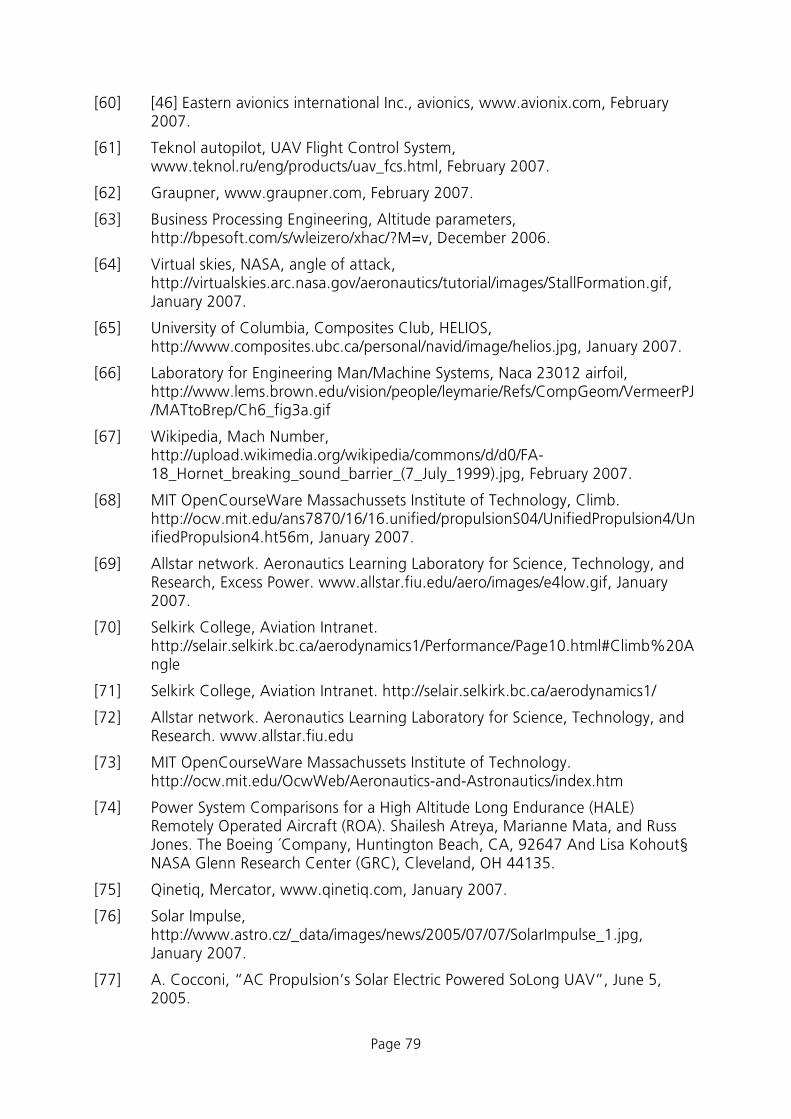
Page 79
[60] [46] Eastern avionics international Inc., avionics, www.avionix.com, February 2007.
[61] Teknol autopilot, UAV Flight Control System, www.teknol.ru/eng/products/uav_fcs.html, February 2007.
[62] Graupner, www.graupner.com, February 2007.
[63] Business Processing Engineering, Altitude parameters, http://bpesoft.com/s/wleizero/xhac/?M=v, December 2006.
[64] Virtual skies, NASA, angle of attack, http://virtualskies.arc.nasa.gov/aeronautics/tutorial/images/StallFormation.gif, January 2007.
[65] University of Columbia, Composites Club, HELIOS, http://www.composites.ubc.ca/personal/navid/image/helios.jpg, January 2007.
[66] Laboratory for Engineering Man/Machine Systems, Naca 23012 airfoil, http://www.lems.brown.edu/vision/people/leymarie/Refs/CompGeom/VermeerPJ/MATtoBrep/Ch6_fig3a.gif
[67] Wikipedia, Mach Number, http://upload.wikimedia.org/wikipedia/commons/d/d0/FA-18_Hornet_breaking_sound_barrier_(7_July_1999).jpg, February 2007.
[68] MIT OpenCourseWare Massachussets Institute of Technology, Climb. http://ocw.mit.edu/ans7870/16/16.unified/propulsionS04/UnifiedPropulsion4/UnifiedPropulsion4.ht56m, January 2007.
[69] Allstar network. Aeronautics Learning Laboratory for Science, Technology, and Research, Excess Power. www.allstar.fiu.edu/aero/images/e4low.gif, January 2007.
[70] Selkirk College, Aviation Intranet. http://selair.selkirk.bc.ca/aerodynamics1/Performance/Page10.html#Climb%20Angle
[71] Selkirk College, Aviation Intranet. http://selair.selkirk.bc.ca/aerodynamics1/
[72] Allstar network. Aeronautics Learning Laboratory for Science, Technology, and Research. www.allstar.fiu.edu
[73] MIT OpenCourseWare Massachussets Institute of Technology. http://ocw.mit.edu/OcwWeb/Aeronautics-and-Astronautics/index.htm
[74] Power System Comparisons for a High Altitude Long Endurance (HALE) Remotely Operated Aircraft (ROA). Shailesh Atreya, Marianne Mata, and Russ Jones. The Boeing ´Company, Huntington Beach, CA, 92647 And Lisa Kohout§ NASA Glenn Research Center (GRC), Cleveland, OH 44135.
[75] Qinetiq, Mercator, www.qinetiq.com, January 2007.
[76] Solar Impulse, http://www.astro.cz/_data/images/news/2005/07/07/SolarImpulse_1.jpg, January 2007.
[77] A. Cocconi, “AC Propulsion’s Solar Electric Powered SoLong UAV”, June 5, 2005.

Page 80

Page 81
IB 124-2007/11
HALE Platforms – A Feasibility Study
Dr. M. Hepperle et al. Distribution:
Dr. Horst Hüners (PD-L) 1 copy Dr. Lutz Dieterle (PD-L) 1 copy Dr. Ulrich Herrmann (PD-L) 1 copy Prof. Dr.-Ing. habil. C.-C. Rossow (AS) 1 copy Prof. Dr.-Ing. Stefan Levedag (FT) 1 copy Prof. Dr.-Ing. Martin Wiedemann (FA) 1 copy Prof. Dr. Richard Bamler (MF) 1 copy Prof. Dr. Christoph Günther (KN) 1 copy Institute of Aerodynamics and Flow Technology (AS) 2 copies Institute of Flight Systems (FT) 2 copies Institute of Composite Structures and Adaptive Systems (FA) 2 copies Institute of Communications and Navigation (KN) 2 copies Cluster Remote Sensing Technology (MF) 2 copies Authors 8 copies TOTAL 26 copies