beryllium copper alloys - ngk-alloys.com and chemical composition (%) 7 physical properties 7...
TRANSCRIPT

Beryllium Copper Alloys Technical Guide
www.ngk-alloys.com
Security Reliability Performance
Table of Contents
Page 1
Page
Introduction 2
Beryllium 2
Age-hardening copper based-alloys 2
Heat treatment and phase diagram of Cu-Be 3
Delivery temper 4
Applications 5
Alloys 6
Copper-beryllium 6
Physical properties 7
Designation and chemical composition (%) 7
Physical properties 7
References Specifications 7
Products 8
Standard products forms 8
Strip and Plate 8
Rod, Bar and Tube 12
Wire 13
Special products 14
Engineering Guide 16
Alloys properties comparison 16
Spring Characteristics 17
Stress relaxation 18
Fatigue strength 20
Elevated temperatures strength 21
Cryogenic properties 21
Wear resistance 22
Magnetic Properties 22
Electrical conductivity 23
Corrosion resistance 25
Manufacturing Technology 27
Stamping and Forming 27
Heat treatment 30
Machining 35
Joining 39
Electrolytic Plating 40
Environment 41
Industrial hygiene 41
European Directive 41
Tables 42
Strip linear density 42
Rod linear density 43
Hardness –conversion table 44
Introduction
Page 2
Beryllium Although the main ore of beryllium, beryl, from the Greek ‘bērullos’ was already known 5000 years before Christ and appreciated as a gemstone, its industrial exploitation really began until 1941. The discovery of beryllium has been attributed to Louis-Nicolas Vauquelin (F) in 1798 at the request of
the mineralogist Hauy, trying to find possible chemical similarity between beryl and emerald. It was in 1828 that Friedrich Whöhler (D) and Antoine Bussy (F) isolated the metal. Vauquelin conferred to this
new identified element the name glucinium based on the Greek 'glikys', by reference to the sweet taste of some of its compounds. The name beryllium was officially given to this element in 1957.
Beryllium (Be) is a mineral extracted from the ground mainly in an oxide state. A bivalent element, beryllium is a steel grey metal that can be mostly found in the minerals, the most important of which are beryl (Be3Al2Si6O18), also called emerald and aquamarine according to its color, and chrysoberyl (Al2BeO4). Pure beryllium is obtained by reduction of beryl or by electrolysis of beryllium chloride. Beryllium is the fourth element on the periodic table. Beryllium metal has excellent thermal conductivity, transparent to X-ray and is nonmagnetic. Beryllium is a light element (density 1.85 g/cm
3), which melts at
1300°C and has a very high Young's modulus. The physical properties of beryllium make an item for various applications in high end products. As metallic material, its uses are relatively limited to aerospace and nuclear industries as well as defense applications.
Age-hardening copper based-alloys The most interesting property of beryllium, which has been instrumental in the development of industrial alloys, is its ability as an addition to cause precipitation hardening in other metals, in particular nickel, aluminum and especially copper. These two alloys owe their development to the fact that the beryllium nickel or copper, can cause hardening of the alloy structural precipitation annealing treatment at low temperature. The copper beryllium alloys are produced from a master alloy of copper and beryllium, containing approximately 4 % of beryllium. The manufacturing process is as follows: 1) Chemical treatment of the ore (beryl), a double aluminium beryllium silicate, to produce a beryllium oxide. 2) Reduction of the beryllium oxide with carbon by calcining in an electric arc furnace in the presence of copper. Copper-beryllium alloys are mainly based on copper with a beryllium addition. High strength beryllium copper alloys contain 0.4 to 2% of beryllium with about 0.3 to 2.7% of other alloying elements such as nickel, cobalt, iron or lead. The high mechanical strength is achieved by precipitation hardening or age hardening.
100
90
80
70
60
50
40
30
20
10
0
Ele
ctri
cal C
on
du
ctiv
ity
(%IA
CS)
0 200 400 600 800 1000 1200 1400 1600
Stainless
Steel
Cu-Ni-Si
Brass
Phosphor
Bronze
CrCu
Copper
Tensile Strength (N/mm2)
B14
B25, B33/25 & B165
B7
B14
B8
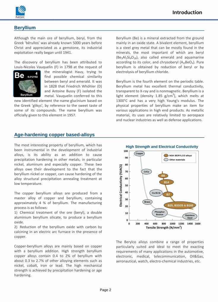
NGK BERYLCO alloys
Other materials
High Strength and Electrical Conductivity
The Berylco alloys combine a range of properties particularly suited and ideal to meet the exacting requirements of many applications in the automotive, electronic, medical, telecommunication, Oil&Gas, aeronautical, watch, electro-chemical industries, etc.
Introduction
Page 3
Very high mechanical properties and improved electrical conductivity can be obtained by means of a simple thermal treatment which produces a structural precipitation hardening. This is the fundamental property of copper beryllium alloys: The alloys can be supplied in tempers which allow
plastic deformation almost equivalent to copper. After forming deep-drawn parts, or parts with complex bends, they can be heat treated to obtain very high mechanical properties
They have very high tensile strength, up to 1500 N/mm
2.
They exhibit an outstanding fatigue strength and excellent resistance to fatigue in reverse bending and vibrations.
Hardness as high as 400 Vickers or Brinell, possibly greater, can be obtained.
They have excellent wear resistance. They present complete resistance to anelastic
behaviour under elastic deformation. They can operate over a wide range of
temperatures, particularly very low cryogenic temperatures, but also at elevated temperatures which are above those normally acceptable for the common copper alloys.
Because they are copper base alloys: Beryllium Copper exhibit a high electrical
conductivity ranges from 22 to 70% IACS depending on the alloys and temper.
They are non-magnetic They have excellent corrosion resistance and are
ideal for use in marine and industrial environments. They have good machinability. They are non-sparking. They have a high fluidity and good castability.
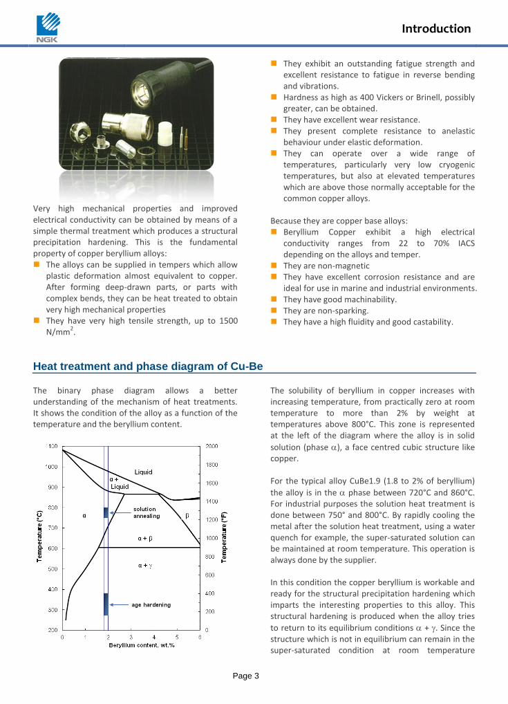
Heat treatment and phase diagram of Cu-Be The binary phase diagram allows a better understanding of the mechanism of heat treatments. It shows the condition of the alloy as a function of the temperature and the beryllium content.
The solubility of beryllium in copper increases with increasing temperature, from practically zero at room temperature to more than 2% by weight at temperatures above 800°C. This zone is represented at the left of the diagram where the alloy is in solid
solution (phase ), a face centred cubic structure like copper. For the typical alloy CuBe1.9 (1.8 to 2% of beryllium)
the alloy is in the phase between 720°C and 860°C. For industrial purposes the solution heat treatment is done between 750° and 800°C. By rapidly cooling the metal after the solution heat treatment, using a water quench for example, the super-saturated solution can be maintained at room temperature. This operation is always done by the supplier. In this condition the copper beryllium is workable and ready for the structural precipitation hardening which imparts the interesting properties to this alloy. This structural hardening is produced when the alloy tries
to return to its equilibrium conditions + . Since the structure which is not in equilibrium can remain in the super-saturated condition at room temperature
Introduction
Page 4
indefinitely, the metal must be heated to accelerate the transformation.
The phase is a beryllium-rich phase (1 atom in 2),
body centered cubic. The formation of this phase
causes a reduction of the beryllium content in the matrix, which in turn improves the electrical and thermal conductivity. At the same time it produces a contraction of the material which amounts to a non-uniform linear shrinkage of about 0.2 % average.
The structural hardening is the result of the
precipitation of the phase which passes trough several intermediary phases. The maximum of hardness for the alloy is produced by these intermediary phases. The precipitation hardening is generally done at temperatures between 300° and 400°C for 15 min to 4 hours at temperature, depending on the type of furnace used and the properties desired.
The maximum mechanical properties are obtained by treatment at 310-330°C for a period of 2 to 3 hours at temperature, depending on the initial temper of the metal. The high conductivity alloys (nickel beryllide in copper) have a range from 0.15 to 0.7 weight percent beryllium. In these alloys most of the beryllium is partitioned to beryllide intermetallics. Coarse beryllides formed during solidication limit grain growth during annealing, while fine beryllides formed during precipitation hardening improve the strength. The temperature ranges for solution annealing and for age hardening are higher for these alloys than for the high strength alloys. The stability of the strengthening phase at elevated temperature in this alloy family results in high resistance to creep and stress relaxation.
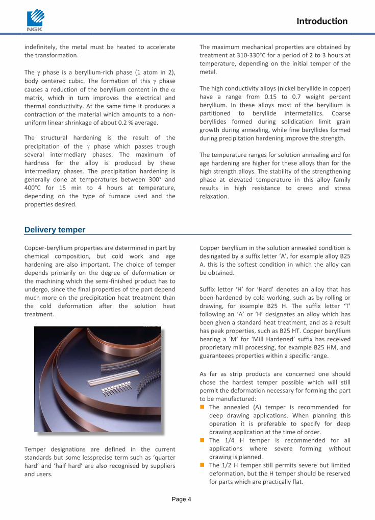
Delivery temper Copper-beryllium properties are determined in part by chemical composition, but cold work and age hardening are also important. The choice of temper depends primarily on the degree of deformation or the machining which the semi-finished product has to undergo, since the final properties of the part depend much more on the precipitation heat treatment than the cold deformation after the solution heat treatment.
Temper designations are defined in the current standards but some lessprecise term such as ‘quarter hard’ and ‘half hard’ are also recognised by suppliers and users.
Copper beryllium in the solution annealed condition is desingated by a suffix letter ‘A’, for example alloy B25 A. this is the softest condition in which the alloy can be obtained. Suffix letter ‘H’ for ‘Hard’ denotes an alloy that has been hardened by cold working, such as by rolling or drawing, for example B25 H. The suffix letter ‘T’ following an ‘A’ or ‘H’ designates an alloy which has been given a standard heat treatment, and as a result has peak properties, such as B25 HT. Copper beryllium bearing a ‘M’ for ‘Mill Hardened’ suffix has received proprietary mill processing, for example B25 HM, and guaranteees properties within a specific range.
As far as strip products are concerned one should chose the hardest temper possible which will still permit the deformation necessary for forming the part to be manufactured: The annealed (A) temper is recommended for
deep drawing applications. When planning this operation it is preferable to specify for deep drawing application at the time of order.
The 1/4 H temper is recommended for all applications where severe forming without drawing is planned.
The 1/2 H temper still permits severe but limited deformation, but the H temper should be reserved for parts which are practically flat.

Introduction
Page 5
The mill hardened tempers offer the advantage of not requiring any heat treatment by the user. However, it must be remembered that the metal in this condition already has the properties required for the finished part and that they must be compatible with the requirements for the forming of the part. The choice of the mill hardened quality must therefore be a
compromise between the characteristics desired for the application and the suitability for forming. For rod and wire products the most suitable temper is ‘cold worked’, and in particular the free machining alloy 33/25. This alloy has a machinability index of about 60 %, while the standard Berylco 25 has an index of about 20 %.
Applications
The Berylco alloys combine a range of properties that make them essential materials and ideal for producing parts with high precision and the most varied complex shapes used in many fields and applications such as: Connectors in the electronic industries (computers,
telecommunications, aerospace, automotive, etc.) Contact springs in the electromechanical, appliance, and
automotive industries Instrument components (diaphragms, bellows, etc.) Springs and flexible parts Friction and wear parts Non-magnetic and non-sparking special tools Plastic injection molds, etc. Demands for cost, quality, comfort, miniaturisation, safety, environmental protection, dimensional tolerances requirements, blemish-free forming surface conditions, and high general performance, are constantly increasing in all these fields and result in new and future great technical challenges requiring suitable high-performance alloys such as copper beryllium.
Security – Reliability – Performance
High strength Hardness
Mecanical parts ; splined shafts, cams, gears, bearings and bearing cages requiring good wear resistance.
High yield strength Clips, washers, springs, diaphragms, bellows, gimbal suspension, requiring good fatigue resistance.
High fatigue resistance Contacts, connectors, relays, switches, all springs subjected to prolonged vibration.
Galling resistance Abrasion resistance
Shells, molds and parts for injection, bearings, valves, etc.
Stress relaxation resistance Automotive applications, aeronautics, space and cryogenic.
Electrical & thermal conductivity Nonmagnetic
Watchmaking, electronic and electrical applications, instrumentation, welding equipments.
Corrosion resistance Formability
Industrial environments (especially petrochemicals), corrosive and marine environment, etc.
Nonsparking Safety tools and applications in explosive and harsh environment.
Alloys
Page 6
Copper-beryllium NGK Berylco is specialised in the manufacture of copper-beryllium alloys. These alloys fall into two distinct categories such as high strength (B25, B33/25 and B165) and high conductivity (B14, B7 and B8). Alloy B14 combines both attributes high strength and high conductivity. Many of our alloys are available in both heat treatable and mill-hardened (pre-heat treated) conditions.
Berylco 25 Alloy B25, containing less than 2% of beryllium, can achieve the highest strength (1500 MPa) and hardness of any commercial copper based alloy in the age hardened condition. In the annealed and low cold-rolled condition, it has an excellent bending formability. Alloy B25 is also delivered in the pre-heat treated (mill-hardened) condition. The strip is age hardened to a specific strength level as part of the manufacturing process prior to shipment. Cost effectiviness is made by elimination of the need for age hardening and cleaning of the stamped parts, as well as avoiding any part distortion. Alloy B25 exhibits some unique combination of properties of mechanical and electrical properties, associated to an excellent formability depending on the tempers. B25 also exhibits exceptional high fatigue life and resistance to stress relaxation at elevated temperatures.
Berylco 165 Alloy B165 exhibits nearly similar mechanical and electrical properties to B25. It contains less beryllium than B25 and is especially used in the humid field. It offers a good strength and is well recommendend for marine applications.
Berylco 33/25 Alloy B33/25 achieves the strength properties of B25 after age hardening with the added benefits of being free machining. Small amount of lead addition promotes formation of finely divided chips and extends cutting tool life, which improve the machinability. Alloy B33/25 rod and wire is suitable for automatic machining operations. In the hardened condition after machining, B33/25 offers a high resistance to fatigue, an excellent resistance to thermal relaxation and a unique combination of
strength and conductivity. It can be locally annealed to allow crimping after hardening and is easily coated with a galvanic layer.
Berylco 14 Alloy B14 contains low beryllium content and can be supplied fully hardened. After special mill-hardened process, the B14 S offers an excellent formability with electrical and thermal conductivity from 45 to 65% of pure copper (typical value: 55% IACS). Delivered in the hardened condition, the B14 S combines excellent stress relaxation resistance at elevated temperature and high mechanical resistance up to 950MPa. No subsequent heat treatment of the stamped parts is required, which reduces production costs and avoids deformation of the finished parts. This alloy offer users the opportunity to upgrade component performance over bronzes and brasses that no other copper alloy about this price range can reach.
Berylco 7 Alloy B7 contains less beryllium and is availableas mill-hardened condition. No further age-hardening is required. It combines the best attributes of both the high strength and high conductivity commercial copper beryllium alloy families. In addition to its high strength and conductivity, B7 has excellent formability, stress resistance at elevated temperature which still exceptional for such grade. This alloy is specially recommended for high batches.
Berylco 8 This alloy is the result of the most recent development of NGK group. Alloy B8 is a copper alloy containing some nickel and about 0.4% of beryllium. B8 strip is supplied in the mill-hardened condition, which somewhat limits its formability but avoids further heat-treatment of the final parts. Amongst the copper-beryllium family, B8 offers the highest electrical conductivity of Berylco alloys (> 60% IACS). Combining a very high thermal electrical conductivity and good mechanical strength, it is used in all applications requiring good crimp and mechanical properties at elevated temperature.
Alloys
Page 7
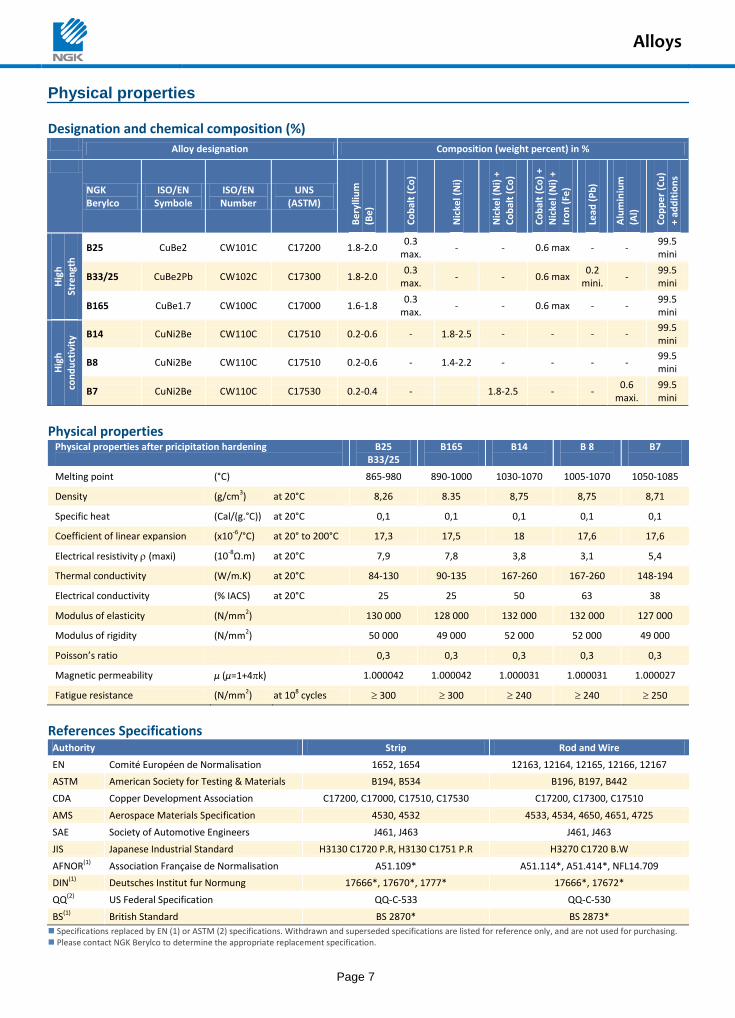
Physical properties
Designation and chemical composition (%) Alloy designation Composition (weight percent) in %
NGK Berylco
ISO/EN Symbole
ISO/EN Number
UNS (ASTM)
Be
rylli
um
(B
e)
Co
bal
t (C
o)
Nic
kel (
Ni)
Nic
kel (
Ni)
+
Co
bal
t (C
o)
Co
bal
t (C
o)
+
Nic
kel (
Ni)
+
Iro
n (
Fe)
Lead
(P
b)
Alu
min
ium
(Al)
Co
pp
er
(Cu
)
+ ad
dit
ion
s
Hig
h
Stre
ngt
h
B25 CuBe2 CW101C C17200 1.8-2.0 0.3
max. - - 0.6 max - -
99.5 mini
B33/25 CuBe2Pb CW102C C17300 1.8-2.0 0.3
max. - - 0.6 max
0.2 mini.
- 99.5 mini
B165 CuBe1.7 CW100C C17000 1.6-1.8 0.3
max. - - 0.6 max - -
99.5 mini
Hig
h
con
du
ctiv
ity B14 CuNi2Be CW110C C17510 0.2-0.6 - 1.8-2.5 - - - -
99.5 mini
B8 CuNi2Be CW110C C17510 0.2-0.6 - 1.4-2.2 - - - - 99.5 mini
B7 CuNi2Be CW110C C17530 0.2-0.4 - 1.8-2.5 - - 0.6
maxi. 99.5 mini
Physical properties Physical properties after pricipitation hardening
B25 B33/25
B165
B14
B 8
B7
Melting point (°C) 865-980 890-1000 1030-1070 1005-1070 1050-1085
Density (g/cm3) at 20°C 8,26 8.35 8,75 8,75 8,71
Specific heat (Cal/(g.°C)) at 20°C 0,1 0,1 0,1 0,1 0,1
Coefficient of linear expansion (x10-6/°C) at 20° to 200°C 17,3 17,5 18 17,6 17,6
Electrical resistivity (maxi) (10-8Ω.m) at 20°C 7,9 7,8 3,8 3,1 5,4
Thermal conductivity (W/m.K) at 20°C 84-130 90-135 167-260 167-260 148-194
Electrical conductivity (% IACS) at 20°C 25 25 50 63 38
Modulus of elasticity (N/mm2) 130 000 128 000 132 000 132 000 127 000
Modulus of rigidity (N/mm2) 50 000 49 000 52 000 52 000 49 000
Poisson’s ratio 0,3 0,3 0,3 0,3 0,3
Magnetic permeability µ (µ=1+4k) 1.000042 1.000042 1.000031 1.000031 1.000027
Fatigue resistance (N/mm2) at 108 cycles 300 300 240 240 250
References Specifications Authority Strip Rod and Wire
EN Comité Européen de Normalisation 1652, 1654 12163, 12164, 12165, 12166, 12167
ASTM American Society for Testing & Materials B194, B534 B196, B197, B442
CDA Copper Development Association C17200, C17000, C17510, C17530 C17200, C17300, C17510
AMS Aerospace Materials Specification 4530, 4532 4533, 4534, 4650, 4651, 4725
SAE Society of Automotive Engineers J461, J463 J461, J463
JIS Japanese Industrial Standard H3130 C1720 P.R, H3130 C1751 P.R H3270 C1720 B.W
AFNOR(1) Association Française de Normalisation A51.109* A51.114*, A51.414*, NFL14.709
DIN(1) Deutsches Institut fur Normung 17666*, 17670*, 1777* 17666*, 17672*
QQ(2) US Federal Specification QQ-C-533 QQ-C-530
BS(1) British Standard BS 2870* BS 2873*
Specifications replaced by EN (1) or ASTM (2) specifications. Withdrawn and superseded specifications are listed for reference only, and are not used for purchasing. Please contact NGK Berylco to determine the appropriate replacement specification.
Products
Page 8
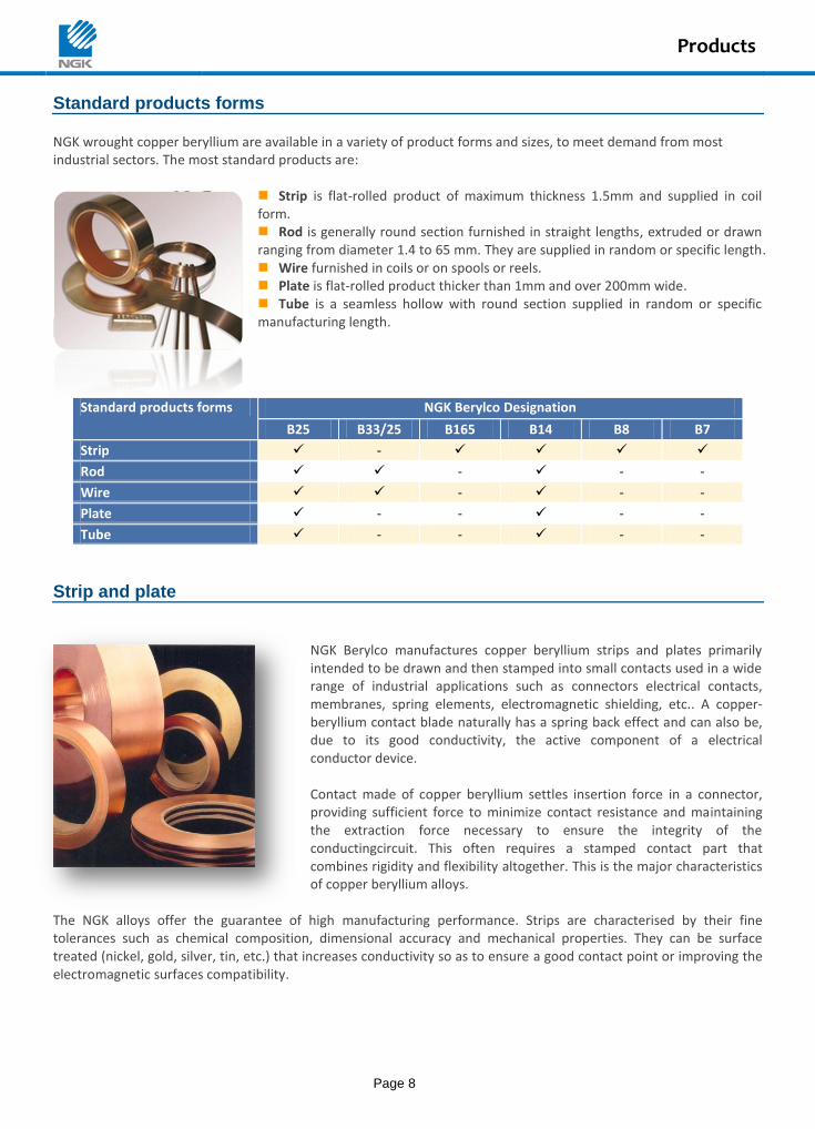
Standard products forms NGK wrought copper beryllium are available in a variety of product forms and sizes, to meet demand from most industrial sectors. The most standard products are:
Strip is flat-rolled product of maximum thickness 1.5mm and supplied in coil form. Rod is generally round section furnished in straight lengths, extruded or drawn ranging from diameter 1.4 to 65 mm. They are supplied in random or specific length. Wire furnished in coils or on spools or reels. Plate is flat-rolled product thicker than 1mm and over 200mm wide. Tube is a seamless hollow with round section supplied in random or specific manufacturing length.
Standard products forms NGK Berylco Designation
B25 B33/25 B165 B14 B8 B7
Strip -
Rod - - -
Wire - - -
Plate - - - -
Tube - - - -
Strip and plate
NGK Berylco manufactures copper beryllium strips and plates primarily intended to be drawn and then stamped into small contacts used in a wide range of industrial applications such as connectors electrical contacts, membranes, spring elements, electromagnetic shielding, etc.. A copper-beryllium contact blade naturally has a spring back effect and can also be, due to its good conductivity, the active component of a electrical conductor device. Contact made of copper beryllium settles insertion force in a connector, providing sufficient force to minimize contact resistance and maintaining the extraction force necessary to ensure the integrity of the conductingcircuit. This often requires a stamped contact part that combines rigidity and flexibility altogether. This is the major characteristics of copper beryllium alloys.
The NGK alloys offer the guarantee of high manufacturing performance. Strips are characterised by their fine tolerances such as chemical composition, dimensional accuracy and mechanical properties. They can be surface treated (nickel, gold, silver, tin, etc.) that increases conductivity so as to ensure a good contact point or improving the electromagnetic surfaces compatibility.
Products
Page 9
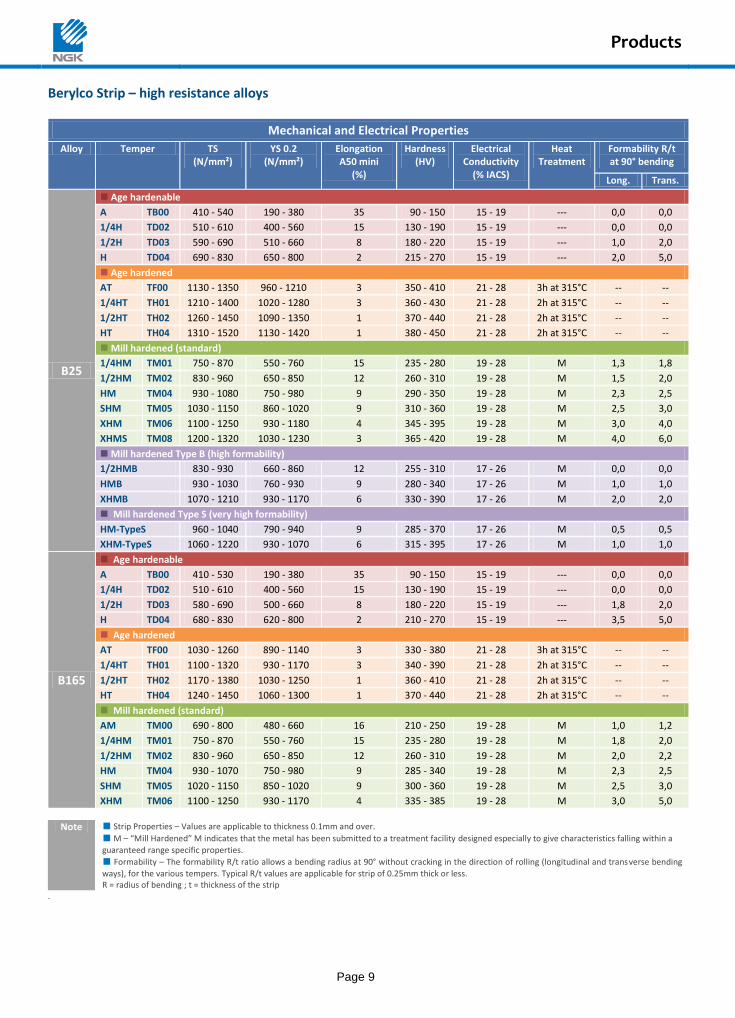
Berylco Strip – high resistance alloys
Mechanical and Electrical Properties
Alloy Temper TS (N/mm²)
YS 0.2 (N/mm²)
Elongation A50 mini
(%)
Hardness (HV)
Electrical Conductivity
(% IACS)
Heat Treatment
Formability R/t at 90° bending
Long. Trans.
B25
Age hardenable
A TB00 410 - 540 190 - 380 35 90 - 150 15 - 19 --- 0,0 0,0
1/4H TD02 510 - 610 400 - 560 15 130 - 190 15 - 19 --- 0,0 0,0
1/2H TD03 590 - 690 510 - 660 8 180 - 220 15 - 19 --- 1,0 2,0
H TD04 690 - 830 650 - 800 2 215 - 270 15 - 19 --- 2,0 5,0
Age hardened
AT TF00 1130 - 1350 960 - 1210 3 350 - 410 21 - 28 3h at 315°C -- --
1/4HT TH01 1210 - 1400 1020 - 1280 3 360 - 430 21 - 28 2h at 315°C -- --
1/2HT TH02 1260 - 1450 1090 - 1350 1 370 - 440 21 - 28 2h at 315°C -- --
HT TH04 1310 - 1520 1130 - 1420 1 380 - 450 21 - 28 2h at 315°C -- --
Mill hardened (standard)
1/4HM TM01 750 - 870 550 - 760 15 235 - 280 19 - 28 M 1,3 1,8
1/2HM TM02 830 - 960 650 - 850 12 260 - 310 19 - 28 M 1,5 2,0
HM TM04 930 - 1080 750 - 980 9 290 - 350 19 - 28 M 2,3 2,5
SHM TM05 1030 - 1150 860 - 1020 9 310 - 360 19 - 28 M 2,5 3,0
XHM TM06 1100 - 1250 930 - 1180 4 345 - 395 19 - 28 M 3,0 4,0
XHMS TM08 1200 - 1320 1030 - 1230 3 365 - 420 19 - 28 M 4,0 6,0
Mill hardened Type B (high formability)
1/2HMB 830 - 930 660 - 860 12 255 - 310 17 - 26 M 0,0 0,0
HMB 930 - 1030 760 - 930 9 280 - 340 17 - 26 M 1,0 1,0
XHMB 1070 - 1210 930 - 1170 6 330 - 390 17 - 26 M 2,0 2,0
Mill hardened Type S (very high formability)
HM-TypeS 960 - 1040 790 - 940 9 285 - 370 17 - 26 M 0,5 0,5
XHM-TypeS 1060 - 1220 930 - 1070 6 315 - 395 17 - 26 M 1,0 1,0
B165
Age hardenable
A TB00 410 - 530 190 - 380 35 90 - 150 15 - 19 --- 0,0 0,0
1/4H TD02 510 - 610 400 - 560 15 130 - 190 15 - 19 --- 0,0 0,0
1/2H TD03 580 - 690 500 - 660 8 180 - 220 15 - 19 --- 1,8 2,0
H TD04 680 - 830 620 - 800 2 210 - 270 15 - 19 --- 3,5 5,0
Age hardened
AT TF00 1030 - 1260 890 - 1140 3 330 - 380 21 - 28 3h at 315°C -- --
1/4HT TH01 1100 - 1320 930 - 1170 3 340 - 390 21 - 28 2h at 315°C -- --
1/2HT TH02 1170 - 1380 1030 - 1250 1 360 - 410 21 - 28 2h at 315°C -- --
HT TH04 1240 - 1450 1060 - 1300 1 370 - 440 21 - 28 2h at 315°C -- --
Mill hardened (standard)
AM TM00 690 - 800 480 - 660 16 210 - 250 19 - 28 M 1,0 1,2
1/4HM TM01 750 - 870 550 - 760 15 235 - 280 19 - 28 M 1,8 2,0
1/2HM TM02 830 - 960 650 - 850 12 260 - 310 19 - 28 M 2,0 2,2
HM TM04 930 - 1070 750 - 980 9 285 - 340 19 - 28 M 2,3 2,5
SHM TM05 1020 - 1150 850 - 1020 9 300 - 360 19 - 28 M 2,5 3,0
XHM TM06 1100 - 1250 930 - 1170 4 335 - 385 19 - 28 M 3,0 5,0
Note Strip Properties – Values are applicable to thickness 0.1mm and over.
M – “Mill Hardened” M indicates that the metal has been submitted to a treatment facility designed especially to give characteristics falling within a
guaranteed range specific properties.
Formability – The formability R/t ratio allows a bending radius at 90° without cracking in the direction of rolling (longitudinal and transverse bending
ways), for the various tempers. Typical R/t values are applicable for strip of 0.25mm thick or less. R = radius of bending ; t = thickness of the strip
.
Products
Page 10
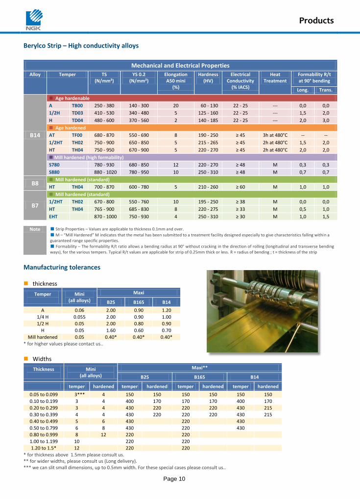
Berylco Strip – High conductivity alloys
Mechanical and Electrical Properties
Alloy Temper TS (N/mm²)
YS 0.2 (N/mm²)
Elongation A50 mini
(%)
Hardness (HV)
Electrical Conductivity
(% IACS)
Heat Treatment
Formability R/t at 90° bending
Long. Trans.
B14
Age hardenable
A TB00 250 - 380 140 - 300 20 60 - 130 22 - 25 --- 0,0 0,0
1/2H TD03 410 - 530 340 - 480 5 125 - 160 22 - 25 --- 1,5 2,0
H TD04 480 - 600 370 - 560 2 140 - 185 22 - 25 --- 2,0 3,0
Age hardened
AT TF00 680 - 870 550 - 690 8 190 - 250 ≥ 45 3h at 480°C -- --
1/2HT TH02 750 - 900 650 - 850 5 215 - 265 ≥ 45 2h at 480°C 1,5 2,0
HT TH04 750 - 950 670 - 900 5 220 - 270 ≥ 45 2h at 480°C 2,0 2,0
Mill hardened (high formability)
S780 780 - 930 680 - 850 12 220 - 270 ≥ 48 M 0,3 0,3
S880 880 - 1020 780 - 950 10 250 - 310 ≥ 48 M 0,7 0,7
B8 Mill hardened (standard)
HT TH04 700 - 870 600 - 780 5 210 - 260 ≥ 60 M 1,0 1,0
B7
Mill hardened (standard)
1/2HT TH02 670 - 800 550 - 760 10 195 - 250 ≥ 38 M 0,0 0,0
HT TH04 765 - 900 685 - 830 8 220 - 275 ≥ 33 M 0,5 1,0
EHT 870 - 1000 750 - 930 4 250 - 310 ≥ 30 M 1,0 1,5
Note Strip Properties – Values are applicable to thickness 0.1mm and over.
M – “Mill Hardened” M indicates that the metal has been submitted to a treatment facility designed especially to give characteristics falling within a guaranteed range specific properties.
Formability – The formability R/t ratio allows a bending radius at 90° without cracking in the direction of rolling (longitudinal and transverse bending
ways), for the various tempers. Typical R/t values are applicable for strip of 0.25mm thick or less. R = radius of bending ; t = thickness of the strip
Manufacturing tolerances thickness
Temper
Mini (all alloys)
Maxi
B25 B165 B14
A 0.06 2.00 0.90 1.20
1/4 H 0.055 2.00 0.90 1.00
1/2 H 0.05 2.00 0.80 0.90
H 0.05 1.60 0.60 0.70
Mill hardened 0.05 0.40* 0.40* 0.40*
* for higher values please contact us..
Widths
Thickness
Mini (all alloys)
Maxi**
B25 B165 B14
temper hardened temper hardened temper hardened temper hardened
0.05 to 0.099 3*** 4 150 150 150 150 150 150
0.10 to 0.199 3 4 400 170 170 170 400 170
0.20 to 0.299 3 4 430 220 220 220 430 215
0.30 to 0.399 4 4 430 220 220 220 430 215
0.40 to 0.499 5 6 430 220 430
0.50 to 0.799 6 8 430 220 430
0.80 to 0.999 8 12 220 220
1.00 to 1.199 10 220 220
1.20 to 1.5* 12 220 220
* for thickness above 1.5mm please consult us. ** for wider widths, please consult us (Long delivery). *** we can slit small dimensions, up to 0.5mm width. For these special cases please consult us..
Products
Page 11
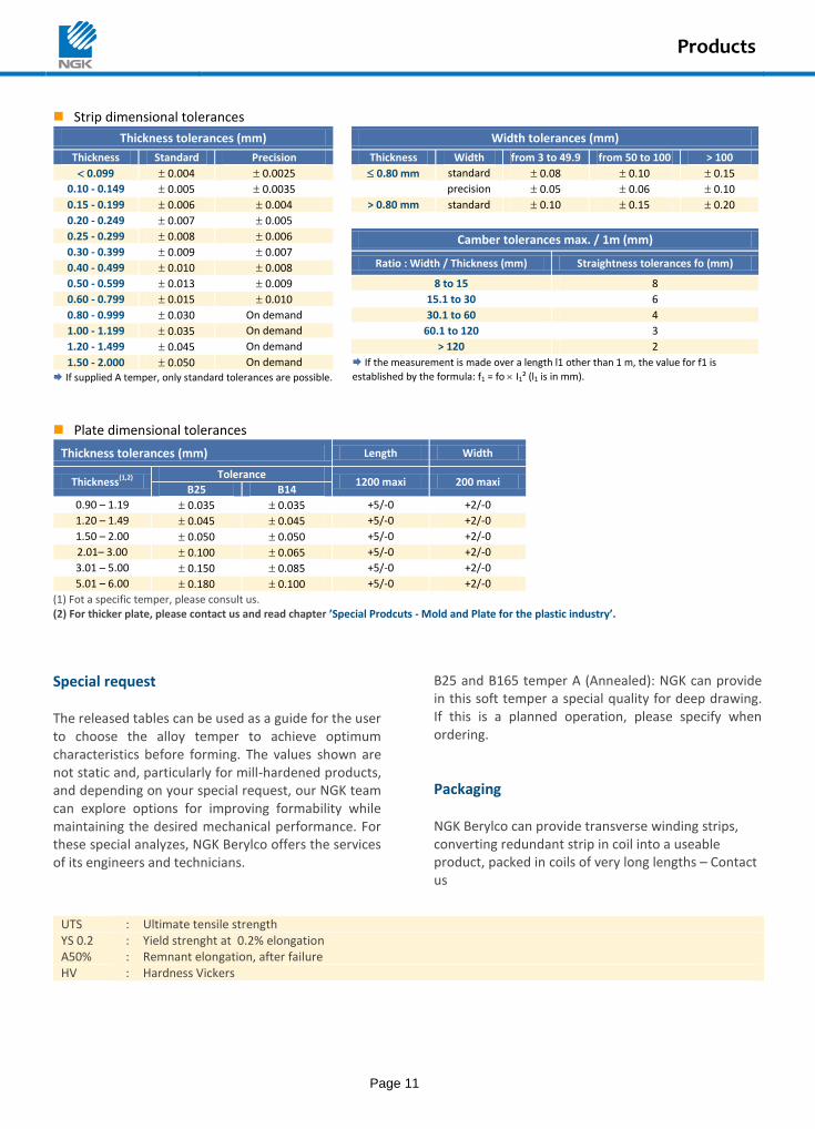
Strip dimensional tolerances
Thickness tolerances (mm) Width tolerances (mm)
Thickness Standard Precision Thickness Width from 3 to 49.9 from 50 to 100 > 100
0.099 0.004 0.0025 0.80 mm standard 0.08 0.10 0.15
0.10 - 0.149 0.005 0.0035 precision 0.05 0.06 0.10
0.15 - 0.199 0.006 0.004 > 0.80 mm standard 0.10 0.15 0.20
0.20 - 0.249 0.007 0.005
0.25 - 0.299 0.008 0.006
Camber tolerances max. / 1m (mm)
0.30 - 0.399 0.009 0.007
Ratio : Width / Thickness (mm) Straightness tolerances fo (mm) 0.40 - 0.499 0.010 0.008
0.50 - 0.599 0.013 0.009 8 to 15 8
0.60 - 0.799 0.015 0.010 15.1 to 30 6
0.80 - 0.999 0.030 On demand 30.1 to 60 4
1.00 - 1.199 0.035 On demand 60.1 to 120 3
1.20 - 1.499 0.045 On demand > 120 2
1.50 - 2.000 0.050 On demand
If the measurement is made over a length l1 other than 1 m, the value for f1 is
established by the formula: f1 = fo I1² (l1 is in mm). If supplied A temper, only standard tolerances are possible.
Plate dimensional tolerances
Thickness tolerances (mm) Length Width
Thickness(1,2) Tolerance
1200 maxi 200 maxi B25 B14
0.90 – 1.19 0.035 0.035 +5/-0 +2/-0
1.20 – 1.49 0.045 0.045 +5/-0 +2/-0
1.50 – 2.00 0.050 0.050 +5/-0 +2/-0
2.01– 3.00 0.100 0.065 +5/-0 +2/-0
3.01 – 5.00 0.150 0.085 +5/-0 +2/-0
5.01 – 6.00 0.180 0.100 +5/-0 +2/-0
(1) Fot a specific temper, please consult us. (2) For thicker plate, please contact us and read chapter ’Special Prodcuts - Mold and Plate for the plastic industry’.
Special request The released tables can be used as a guide for the user to choose the alloy temper to achieve optimum characteristics before forming. The values shown are not static and, particularly for mill-hardened products, and depending on your special request, our NGK team can explore options for improving formability while maintaining the desired mechanical performance. For these special analyzes, NGK Berylco offers the services of its engineers and technicians.
B25 and B165 temper A (Annealed): NGK can provide in this soft temper a special quality for deep drawing. If this is a planned operation, please specify when ordering.
Packaging NGK Berylco can provide transverse winding strips, converting redundant strip in coil into a useable product, packed in coils of very long lengths – Contact us
UTS : Ultimate tensile strength YS 0.2 : Yield strenght at 0.2% elongation A50% : Remnant elongation, after failure HV : Hardness Vickers
Products
Page 12
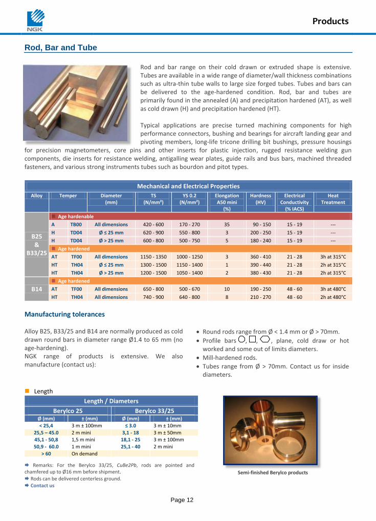
Rod, Bar and Tube
Rod and bar range on their cold drawn or extruded shape is extensive. Tubes are available in a wide range of diameter/wall thickness combinations such as ultra-thin tube walls to large size forged tubes. Tubes and bars can be delivered to the age-hardened condition. Rod, bar and tubes are primarily found in the annealed (A) and precipitation hardened (AT), as well as cold drawn (H) and precipitation hardened (HT). Typical applications are precise turned machining components for high performance connectors, bushing and bearings for aircraft landing gear and pivoting members, long-life tricone drilling bit bushings, pressure housings
for precision magnetometers, core pins and other inserts for plastic injection, rugged resistance welding gun components, die inserts for resistance welding, antigalling wear plates, guide rails and bus bars, machined threaded fasteners, and various strong instruments tubes such as bourdon and pitot types.
Mechanical and Electrical Properties
Alloy Temper Diameter (mm)
TS (N/mm²)
YS 0.2 (N/mm²)
Elongation A50 mini
(%)
Hardness (HV)
Electrical Conductivity
(% IACS)
Heat Treatment
B25 &
B33/25
Age hardenable
A TB00 All dimensions 420 - 600 170 - 270 35 90 - 150 15 - 19 ---
H TD04 Ø ≤ 25 mm 620 - 900 550 - 800 3 200 - 250 15 - 19 ---
H TD04 Ø > 25 mm 600 - 800 500 - 750 5 180 - 240 15 - 19 ---
Age hardened
AT TF00 All dimensions 1150 - 1350 1000 - 1250 3 360 - 410 21 - 28 3h at 315°C
HT TH04 Ø ≤ 25 mm 1300 - 1500 1150 - 1400 1 390 - 440 21 - 28 2h at 315°C
HT TH04 Ø > 25 mm 1200 - 1500 1050 - 1400 2 380 - 430 21 - 28 2h at 315°C
B14
Age hardened
AT TF00 All dimensions 650 - 800 500 - 670 10 190 - 250 48 - 60 3h at 480°C
HT TH04 All dimensions 740 - 900 640 - 800 8 210 - 270 48 - 60 2h at 480°C
Manufacturing tolerances Alloy B25, B33/25 and B14 are normally produced as cold drawn round bars in diameter range Ø1.4 to 65 mm (no age-hardening). NGK range of products is extensive. We also manufacture (contact us):
Round rods range from Ø < 1.4 mm or Ø > 70mm.
Profile bars , , , plane, cold draw or hot worked and some out of limits diameters.
Mill-hardened rods.
Tubes range from Ø > 70mm. Contact us for inside diameters.
Length
Length / Diameters
Semi-finished Berylco products
Berylco 25 Berylco 33/25 Ø (mm) ± (mm) Ø (mm) ± (mm)
< 25,4 3 m ± 100mm ≤ 3.0 3 m ± 10mm
25,5 – 45.0 2 m mini 3,1 - 18 3 m ± 50mm
45,1 - 50,8 1,5 m mini 18,1 - 25 3 m ± 100mm
50,9 - 60.0 1 m mini 25,1 - 40 2 m mini
> 60 On demand
Remarks: For the Berylco 33/25, CuBe2Pb, rods are pointed and chamfered up to Ø16 mm before shipment.
Rods can be delivered centerless ground.
Contact us
Products
Page 13
Dimensional tolerances
Dimensional tolerances
Berylco 25 (age hardenable)
Berylco 33/25 (age hardenable)
Ø (mm) ± (mm) Ø (mm) ± (mm)
1,4 - 3.0 h9 : +0, -0,025 0,9 - 2,3 h8 : +0, - 0.014
3,1 - 6.0 h9 : +0, -0,030 2.4 - 3.0 h8 : +0, - 0.014
6,1 - 10.0 h9 : +0, -0,036 3.1 - 6.0 h8 : +0, - 0.018
10,1 - 18.0 h10 : +0, -0,070 6.1 - 10.0 h8 : +0, - 0.022
18,1 - 25.0 h10 : +0, -0,084 10.1 - 13.0 h8 : +0, - 0.027
25,1 - 30.0 h11 : +0, -0,130 13.1 - 18.0 h9 : +0, - 0.043
30,1 - 50.0 h11 : +0, -0,160 18.1 - 25.4 h9 : +0, - 0.052
50,1 - 60.0 h11 : +0, -0,190 25.5 - 30.0 h10 : +0, - 0.084
30.1 - 40.0 h10 : +0, - 0.100
NGK Berylco can also supply some profile rods (square, rectangular and hexagonal) cold drawn or hot worked, and some non-standard sizes. Round rod cold drawn in
* For heat treated rods, please consult us.
Shape tolerances Shape tolerance (circularity to products with a circular section), defined as the difference between the largest and the smallest dimension, measured on a same cross section of a rod or wire, is equal to half tolerance on diameter or flat.
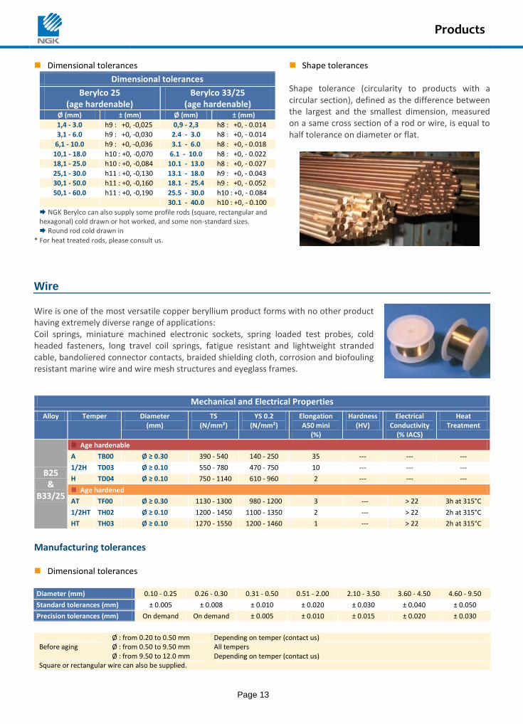
Wire Wire is one of the most versatile copper beryllium product forms with no other product having extremely diverse range of applications: Coil springs, miniature machined electronic sockets, spring loaded test probes, cold headed fasteners, long travel coil springs, fatigue resistant and lightweight stranded cable, bandoliered connector contacts, braided shielding cloth, corrosion and biofouling resistant marine wire and wire mesh structures and eyeglass frames.
Mechanical and Electrical Properties
Alloy Temper Diameter (mm)
TS (N/mm²)
YS 0.2 (N/mm²)
Elongation A50 mini
(%)
Hardness (HV)
Electrical Conductivity
(% IACS)
Heat Treatment
B25 &
B33/25
Age hardenable
A TB00 Ø ≥ 0.30 390 - 540 140 - 250 35 --- --- ---
1/2H TD03 Ø ≥ 0.10 550 - 780 470 - 750 10 --- --- ---
H TD04 Ø ≥ 0.10 750 - 1140 610 - 960 2 --- --- ---
Age hardened
AT TF00 Ø ≥ 0.30 1130 - 1300 980 - 1200 3 --- > 22 3h at 315°C
1/2HT TH02 Ø ≥ 0.10 1200 - 1450 1100 - 1350 2 --- > 22 2h at 315°C
HT TH03 Ø ≥ 0.10 1270 - 1550 1200 - 1460 1 --- > 22 2h at 315°C
Manufacturing tolerances Dimensional tolerances Diameter (mm) 0.10 - 0.25 0.26 - 0.30 0.31 - 0.50 0.51 - 2.00 2.10 - 3.50 3.60 - 4.50 4.60 - 9.50
Standard tolerances (mm) ± 0.005 ± 0.008 ± 0.010 ± 0.020 ± 0.030 ± 0.040 ± 0.050
Precision tolerances (mm) On demand On demand ± 0.005 ± 0.010 ± 0.015 ± 0.020 ± 0.030
Ø : from 0.20 to 0.50 mm Depending on temper (contact us) Before aging Ø : from 0.50 to 9.50 mm All tempers Ø : from 9.50 to 12.0 mm Depending on temper (contact us) Square or rectangular wire can also be supplied.
Products
Page 14
Special products In addition to the strip, wire and rod semi-finished products, NGK Berylco include a large variety of wrought products such as foundry alloys (casting ingots, master alloys to 4%), Chill-Vents, forged rods, plates, tubes, Microtubes, profiles, safety tools, etc.
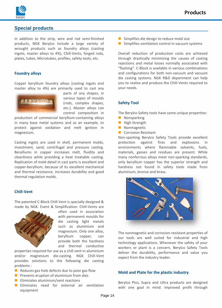
Foundry alloys Copper beryllium foundry alloys (casting ingots and master alloy to 4%) are primarily used to cast any
parts of any shapes, in various types of moulds (rods, complex shapes, etc.). Master alloys can control composition in
production of commercial beryllium-containing alloys in many base metal systems and as an example, to protect against oxidation and melt ignition in magnesium. Casting ingots are used in shell, permanent molds, investment, sand, centrifugal and pressure casting. Berylliums in copper increases melt, fluidity and cleanliness while providing a heat treatable casting. Replication of mold detail in cast parts is excellent and copper-beryllium, because of its excellent mechanical and thermal resistance, increases durability and good thermal regulation molds.
Chill-Vent The patented C-Block Chill-Vent is specially designed & made by NGK. Event & Simplification: Chill-Vents are
often used in association with permanent moulds for die casting light metals such as aluminium and magnesium. Only one alloy, beryllium copper, can provide both the hardness and thermal conductive
properties required for use as a chill vent in aluminium and/or magnesium die-casting. NGK Chill-Vent provides solutions to the following die casting problems : Reduces gas hole defects due to poor gas flow Prevents eruption of aluminium from dies Eliminates aluminium/vent reactions Eliminates need for external air ventilation
equipment
Simplifies die design to reduce mold size Simplifies ventilation control in vacuum systems Overall reduction of production costs are achieved through drastically minimizing the causes of casting rejections and metal losses normally associated with "flashing". C-Block is available in various combinations and configurations for both non-vacuum and vacuum die casting systems. NGK R&D department can help you to realise and produce the Chill-Vents required to your needs.
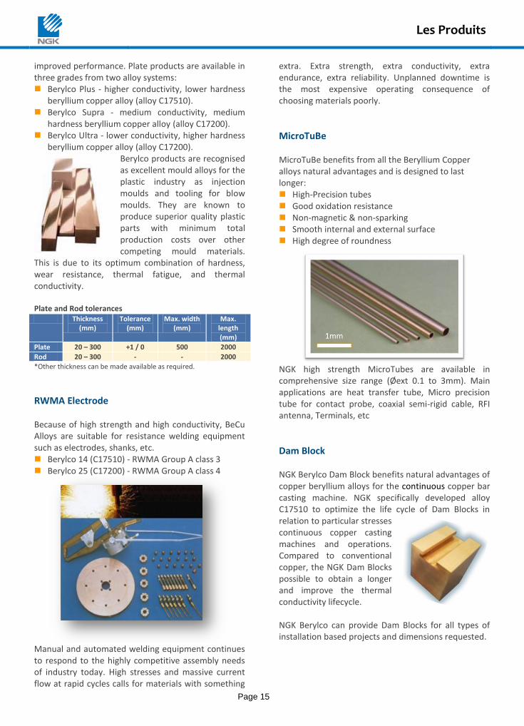
Safety Tool The Berylco Safety tools have some unique properties: Nonsparking High Strength Nonmagnetic Corrosion Resistant Non-sparking Berylco Safety Tools provide excellent protection against fires and explosions in environments where flammable solvents, fuels, materials, gasses and residues are present. While many nonferrous alloys meet non-sparking standards, only beryllium copper has the superior strength and hardness not found in safety tools made from aluminium, bronze and brass.
The nonmagnetic and corrosion-resistant properties of our tools are well suited for industrial and high technology applications. Whenever the safety of your workers or plant is a concern, Berylco Safety Tools deliver the durability, performance and value you expect from the industry leader.
Mold and Plate for the plastic industry Berylco Plus, Supra and Ultra products are designed with one goal in mind. Improved profit through
Les Produits
Page 15
improved performance. Plate products are available in three grades from two alloy systems: Berylco Plus - higher conductivity, lower hardness
beryllium copper alloy (alloy C17510). Berylco Supra - medium conductivity, medium
hardness beryllium copper alloy (alloy C17200). Berylco Ultra - lower conductivity, higher hardness
beryllium copper alloy (alloy C17200). Berylco products are recognised as excellent mould alloys for the plastic industry as injection moulds and tooling for blow moulds. They are known to produce superior quality plastic parts with minimum total production costs over other competing mould materials.
This is due to its optimum combination of hardness, wear resistance, thermal fatigue, and thermal conductivity. Plate and Rod tolerances
Thickness (mm)
Tolerance (mm)
Max. width (mm)
Max. length (mm)
Plate 20 – 300 +1 / 0 500 2000
Rod 20 – 300 - - 2000
*Other thickness can be made available as required.
RWMA Electrode
Because of high strength and high conductivity, BeCu Alloys are suitable for resistance welding equipment such as electrodes, shanks, etc. Berylco 14 (C17510) - RWMA Group A class 3 Berylco 25 (C17200) - RWMA Group A class 4
Manual and automated welding equipment continues to respond to the highly competitive assembly needs of industry today. High stresses and massive current flow at rapid cycles calls for materials with something
extra. Extra strength, extra conductivity, extra endurance, extra reliability. Unplanned downtime is the most expensive operating consequence of choosing materials poorly.
MicroTuBe
MicroTuBe benefits from all the Beryllium Copper alloys natural advantages and is designed to last longer: High-Precision tubes Good oxidation resistance Non-magnetic & non-sparking Smooth internal and external surface High degree of roundness
NGK high strength MicroTubes are available in comprehensive size range (Øext 0.1 to 3mm). Main applications are heat transfer tube, Micro precision tube for contact probe, coaxial semi-rigid cable, RFI antenna, Terminals, etc
Dam Block
NGK Berylco Dam Block benefits natural advantages of copper beryllium alloys for the continuous copper bar casting machine. NGK specifically developed alloy C17510 to optimize the life cycle of Dam Blocks in relation to particular stresses continuous copper casting machines and operations. Compared to conventional copper, the NGK Dam Blocks possible to obtain a longer and improve the thermal conductivity lifecycle. NGK Berylco can provide Dam Blocks for all types of installation based projects and dimensions requested.
Engineering Guide
Page 16
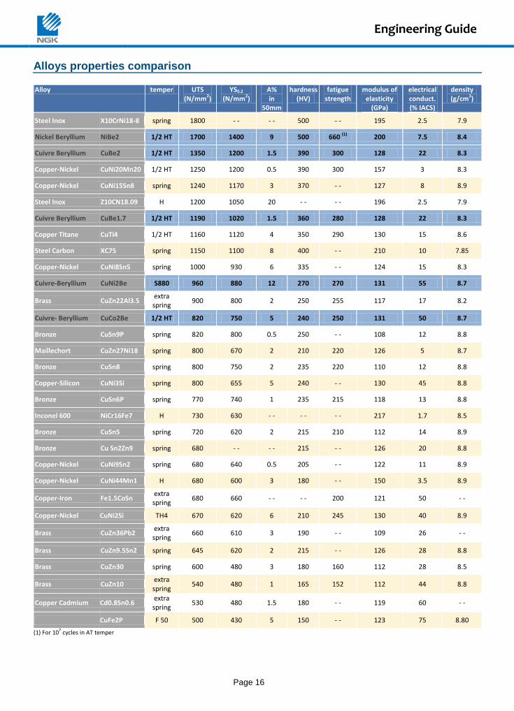
Alloys properties comparison Alloy temper UTS
(N/mm2) YS0.2
(N/mm2) A% in
50mm
hardness (HV)
fatigue strength
modulus of elasticity
(GPa)
electrical conduct. (% IACS)
density (g/cm3)
Steel Inox X10CrNi18-8 spring 1800 - - - - 500 - - 195 2.5 7.9
Nickel Beryllium NiBe2 1/2 HT 1700 1400 9 500 660 (1) 200 7.5 8.4
Cuivre Beryllium CuBe2 1/2 HT 1350 1200 1.5 390 300 128 22 8.3
Copper-Nickel CuNi20Mn20 1/2 HT 1250 1200 0.5 390 300 157 3 8.3
Copper-Nickel CuNi15Sn8 spring 1240 1170 3 370 - - 127 8 8.9
Steel Inox Z10CN18.09 H 1200 1050 20 - - - - 196 2.5 7.9
Cuivre Beryllium CuBe1.7 1/2 HT 1190 1020 1.5 360 280 128 22 8.3
Copper Titane CuTi4 1/2 HT 1160 1120 4 350 290 130 15 8.6
Steel Carbon XC75 spring 1150 1100 8 400 - - 210 10 7.85
Copper-Nickel CuNi8Sn5 spring 1000 930 6 335 - - 124 15 8.3
Cuivre-Beryllium CuNi2Be S880 960 880 12 270 270 131 55 8.7
Brass CuZn22Al3.5 extra spring
900 800 2 250 255 117 17 8.2
Cuivre- Beryllium CuCo2Be 1/2 HT 820 750 5 240 250 131 50 8.7
Bronze CuSn9P spring 820 800 0.5 250 - - 108 12 8.8
Maillechort CuZn27Ni18 spring 800 670 2 210 220 126 5 8.7
Bronze CuSn8 spring 800 750 2 235 220 110 12 8.8
Copper-Silicon CuNi3Si spring 800 655 5 240 - - 130 45 8.8
Bronze CuSn6P spring 770 740 1 235 215 118 13 8.8
Inconel 600 NiCr16Fe7 H 730 630 - - - - - - 217 1.7 8.5
Bronze CuSn5 spring 720 620 2 215 210 112 14 8.9
Bronze Cu Sn2Zn9 spring 680 - - - - 215 - - 126 20 8.8
Copper-Nickel CuNi9Sn2 spring 680 640 0.5 205 - - 122 11 8.9
Copper-Nickel CuNi44Mn1 H 680 600 3 180 - - 150 3.5 8.9
Copper-Iron Fe1.5CoSn extra spring
680 660 - - - - 200 121 50 - -
Copper-Nickel CuNi2Si TH4 670 620 6 210 245 130 40 8.9
Brass CuZn36Pb2 extra spring
660 610 3 190 - - 109 26 - -
Brass CuZn9.5Sn2 spring 645 620 2 215 - - 126 28 8.8
Brass CuZn30 spring 600 480 3 180 160 112 28 8.5
Brass CuZn10 extra spring
540 480 1 165 152 112 44 8.8
Copper Cadmium Cd0.8Sn0.6 extra spring
530 480 1.5 180 - - 119 60 - -
CuFe2P F 50 500 430 5 150 - - 123 75 8.80
(1) For 107 cycles in AT temper
Engineering Guide
Page 17
Spring Characteristics In general, the most important properties of a spring, whatever its application, are the elastic properties of the materials such as the elastic limit, the modulus of elasticity, the fatigue strength or retention of properties with time.
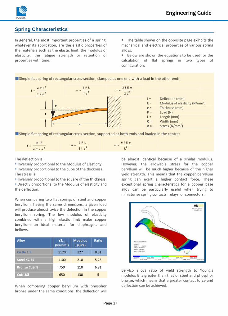
The table shown on the opposite page exihbits the mechanical and electrical properties of various spring alloys. Below are shown the equations to be used for the calculation of flat springs in two types of configuration:
Simple flat spring of rectangular cross-section, clamped at one end with a load in the other end:
3
3
e E
L P 4f
2
e
L P 6
2L 2
e E f 3
f = Deflection (mm) E = Modulus of elasticity (N/mm
2)
e = Thickness (mm) P = Load (N) L = Length (mm) ℓ = Width (mm) σ = Stress (N/mm
2)
Simple flat spring of rectangular cross-section, supported at both ends and loaded in the centre:
3
3
e E 4
L P f
2
e 2
L P 3
2L
e E f 6
The deflection is: Inversely proportional to the Modulus of Elasticity. Inversely proportional to the cube of the thickness. The stress is: Inversely proportional to the square of the thickness. Directly proportional to the Modulus of elasticity and the deflection. When comparing two flat springs of steel and copper beryllium, having the same dimensions, a given load will produce almost twice the defection in the copper beryllium spring. The low modulus of elasticity combined with a high elastic limit make copper beryllium an ideal material for diaphragms and bellows.
Alloy
YS0.2
(N/mm2)
Modulus E (GPa)
Ratio
Cu Be 1.9 1120 127 8.81
Steel XC 75 1100 210 5.23
Bronze CuSn8 750 110 6.81
CuNi3Si 650 130 5
When comparing copper beryllium with phosphor bronze under the same conditions, the deflection will
be almost identical because of a similar modulus. However, the allowable stress for the copper beryllium will be much higher because of the higher yield strength. This means that the copper beryllium spring can exert a higher contact force. These exceptional spring characteristics for a copper base alloy can be particularly useful when trying to miniaturise spring contacts, relays, or connectors.
Berylco alloys ratio of yield strength to Young's modulus E is greater than that of steel and phosphor bronze, which means that a greater contact force and deflection can be achieved.
Engineering Guide
Page 18
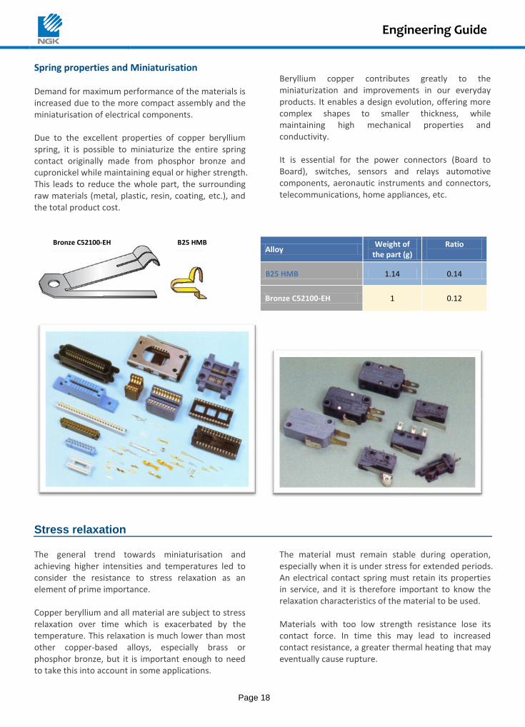
Spring properties and Miniaturisation Demand for maximum performance of the materials is increased due to the more compact assembly and the miniaturisation of electrical components. Due to the excellent properties of copper beryllium spring, it is possible to miniaturize the entire spring contact originally made from phosphor bronze and cupronickel while maintaining equal or higher strength. This leads to reduce the whole part, the surrounding raw materials (metal, plastic, resin, coating, etc.), and the total product cost.
Beryllium copper contributes greatly to the miniaturization and improvements in our everyday products. It enables a design evolution, offering more complex shapes to smaller thickness, while maintaining high mechanical properties and conductivity. It is essential for the power connectors (Board to Board), switches, sensors and relays automotive components, aeronautic instruments and connectors, telecommunications, home appliances, etc.
Alloy Weight of
the part (g) Ratio
B25 HMB 1.14 0.14
Bronze C52100-EH 1 0.12
Stress relaxation The general trend towards miniaturisation and achieving higher intensities and temperatures led to consider the resistance to stress relaxation as an element of prime importance. Copper beryllium and all material are subject to stress relaxation over time which is exacerbated by the temperature. This relaxation is much lower than most other copper-based alloys, especially brass or phosphor bronze, but it is important enough to need to take this into account in some applications.
The material must remain stable during operation, especially when it is under stress for extended periods. An electrical contact spring must retain its properties in service, and it is therefore important to know the relaxation characteristics of the material to be used. Materials with too low strength resistance lose its contact force. In time this may lead to increased contact resistance, a greater thermal heating that may eventually cause rupture.
B25 HMB Bronze C52100-EH
Engineering Guide
Page 19
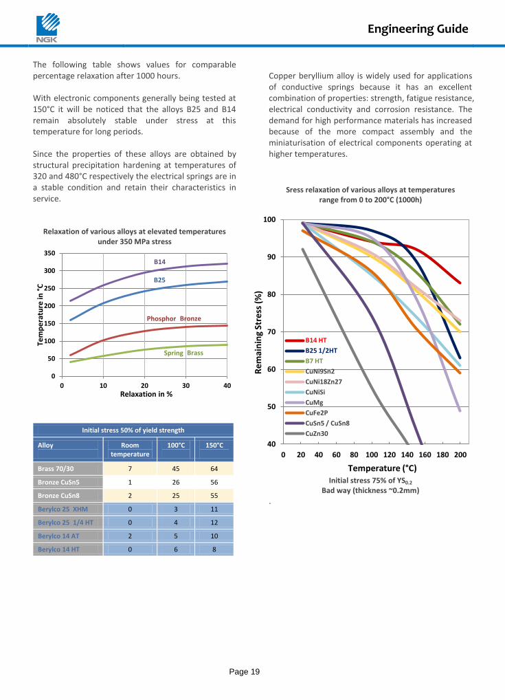
The following table shows values for comparable percentage relaxation after 1000 hours. With electronic components generally being tested at 150°C it will be noticed that the alloys B25 and B14 remain absolutely stable under stress at this temperature for long periods. Since the properties of these alloys are obtained by structural precipitation hardening at temperatures of 320 and 480°C respectively the electrical springs are in a stable condition and retain their characteristics in service.
Relaxation of various alloys at elevated temperatures under 350 MPa stress
Initial stress 50% of yield strength
Alloy
Room temperature
100°C
150°C
Brass 70/30 7 45 64
Bronze CuSn5 1 26 56
Bronze CuSn8 2 25 55
Berylco 25 XHM 0 3 11
Berylco 25 1/4 HT 0 4 12
Berylco 14 AT 2 5 10
Berylco 14 HT 0 6 8
Copper beryllium alloy is widely used for applications of conductive springs because it has an excellent combination of properties: strength, fatigue resistance, electrical conductivity and corrosion resistance. The demand for high performance materials has increased because of the more compact assembly and the miniaturisation of electrical components operating at higher temperatures.
Sress relaxation of various alloys at temperatures
range from 0 to 200°C (1000h)
Initial stress 75% of YS0.2
Bad way (thickness ~0.2mm)
.
Phosphor
B14
B25
Brass Spring
Bronze
0
50
100
150
200
250
300
350
0 10 20 30 40
Tem
pe
ratu
re in
°C
Relaxation in %
40
50
60
70
80
90
100
0 20 40 60 80 100 120 140 160 180 200
Rem
ain
ing
Stre
ss (
%)
Temperature (°C)
B14 HT
B25 1/2HT
B7 HT
CuNi9Sn2
CuNi18Zn27
CuNiSi
CuMg
CuFe2P
CuSn5 / CuSn8
CuZn30
Engineering Guide
Page 20
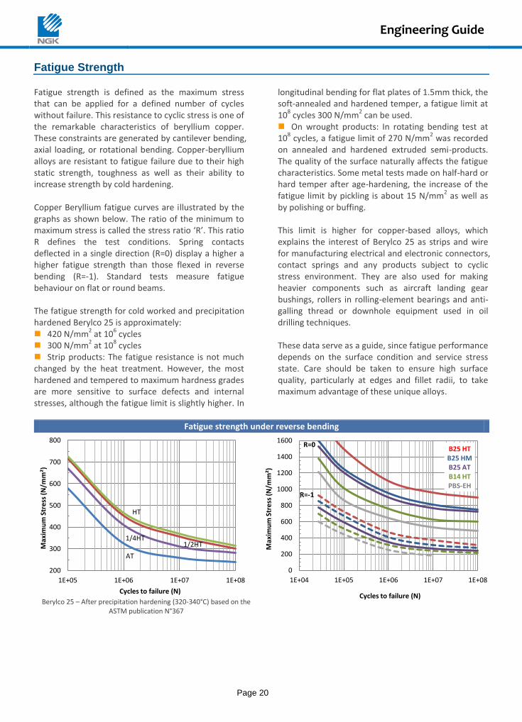
Fatigue Strength Fatigue strength is defined as the maximum stress that can be applied for a defined number of cycles without failure. This resistance to cyclic stress is one of the remarkable characteristics of beryllium copper. These constraints are generated by cantilever bending, axial loading, or rotational bending. Copper-beryllium alloys are resistant to fatigue failure due to their high static strength, toughness as well as their ability to increase strength by cold hardening. Copper Beryllium fatigue curves are illustrated by the graphs as shown below. The ratio of the minimum to maximum stress is called the stress ratio ‘R’. This ratio R defines the test conditions. Spring contacts deflected in a single direction (R=0) display a higher a higher fatigue strength than those flexed in reverse bending (R=-1). Standard tests measure fatigue behaviour on flat or round beams. The fatigue strength for cold worked and precipitation hardened Berylco 25 is approximately: 420 N/mm
2 at 10
6 cycles
300 N/mm2 at 10
8 cycles
Strip products: The fatigue resistance is not much changed by the heat treatment. However, the most hardened and tempered to maximum hardness grades are more sensitive to surface defects and internal stresses, although the fatigue limit is slightly higher. In
longitudinal bending for flat plates of 1.5mm thick, the soft-annealed and hardened temper, a fatigue limit at 10
8 cycles 300 N/mm
2 can be used.
On wrought products: In rotating bending test at 10
8 cycles, a fatigue limit of 270 N/mm
2 was recorded
on annealed and hardened extruded semi-products. The quality of the surface naturally affects the fatigue characteristics. Some metal tests made on half-hard or hard temper after age-hardening, the increase of the fatigue limit by pickling is about 15 N/mm
2 as well as
by polishing or buffing. This limit is higher for copper-based alloys, which explains the interest of Berylco 25 as strips and wire for manufacturing electrical and electronic connectors, contact springs and any products subject to cyclic stress environment. They are also used for making heavier components such as aircraft landing gear bushings, rollers in rolling-element bearings and anti-galling thread or downhole equipment used in oil drilling techniques. These data serve as a guide, since fatigue performance depends on the surface condition and service stress state. Care should be taken to ensure high surface quality, particularly at edges and fillet radii, to take maximum advantage of these unique alloys.
Fatigue strength under reverse bending
Berylco 25 – After precipitation hardening (320-340°C) based on the
ASTM publication N°367
HT
1/2HT 1/4HT
AT
200
300
400
500
600
700
800
1E+05 1E+06 1E+07 1E+08
Max
imu
m S
tre
ss (
N/m
m²)
Cycles to failure (N)
R=0
R=-1
B25 HT B25 HM B25 AT B14 HT PBS-EH
0
200
400
600
800
1000
1200
1400
1600
1E+04 1E+05 1E+06 1E+07 1E+08
Max
imu
m S
tre
ss (
N/m
m²)
Cycles to failure (N)
Engineering Guide
Page 21
Elevated temperatures strength
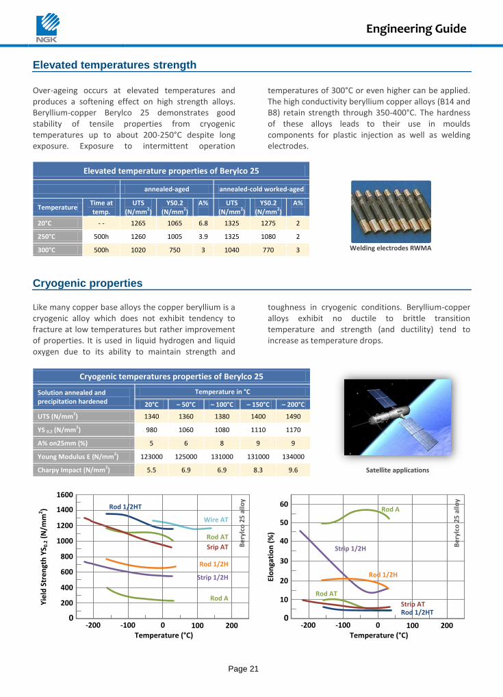
Over-ageing occurs at elevated temperatures and produces a softening effect on high strength alloys. Beryllium-copper Berylco 25 demonstrates good stability of tensile properties from cryogenic temperatures up to about 200-250°C despite long exposure. Exposure to intermittent operation
temperatures of 300°C or even higher can be applied. The high conductivity beryllium copper alloys (B14 and B8) retain strength through 350-400°C. The hardness of these alloys leads to their use in moulds components for plastic injection as well as welding electrodes.
Elevated temperature properties of Berylco 25
annealed-aged annealed-cold worked-aged
Welding electrodes RWMA
Temperature Time at temp.
UTS (N/mm2)
YS0.2 (N/mm2)
A%
UTS (N/mm2)
YS0.2 (N/mm2)
A%
20°C - - 1265 1065 6.8 1325 1275 2
250°C 500h 1260 1005 3.9 1325 1080 2
300°C 500h 1020 750 3 1040 770 3
Cryogenic properties Like many copper base alloys the copper beryllium is a cryogenic alloy which does not exhibit tendency to fracture at low temperatures but rather improvement of properties. It is used in liquid hydrogen and liquid oxygen due to its ability to maintain strength and
toughness in cryogenic conditions. Beryllium-copper alloys exhibit no ductile to brittle transition temperature and strength (and ductility) tend to increase as temperature drops.
Cryogenic temperatures properties of Berylco 25
Satellite applications
Solution annealed and precipitation hardened
Temperature in °C
20°C – 50°C – 100°C – 150°C – 200°C
UTS (N/mm2) 1340 1360 1380 1400 1490
YS 0.2 (N/mm2) 980 1060 1080 1110 1170
A% on25mm (%) 5 6 8 9 9
Young Modulus E (N/mm2) 123000 125000 131000 131000 134000
Charpy Impact (N/mm2) 5.5 6.9 6.9 8.3 9.6
1400
1200
1000
800
600
400
200
Temperature (°C)1000 200-200 -100
1600
0
Wire AT
Rod 1/2HT
Rod AT
Srip AT
Rod 1/2H
Strip 1/2H
Rod A
Yie
ld S
tre
ngt
h Y
S 0.2
(N
/mm
2)
60
50
40
30
20
10
Temperature (°C)1000 200-200 -100
0Rod 1/2HT
Rod AT
Strip AT
Rod 1/2H
Strip 1/2H
Rod A
Elo
nga
tio
n (
%)
Be
rylc
o 2
5 a
lloy
Be
rylc
o 2
5 a
lloy
Engineering Guide
Page 22
Wear resistance
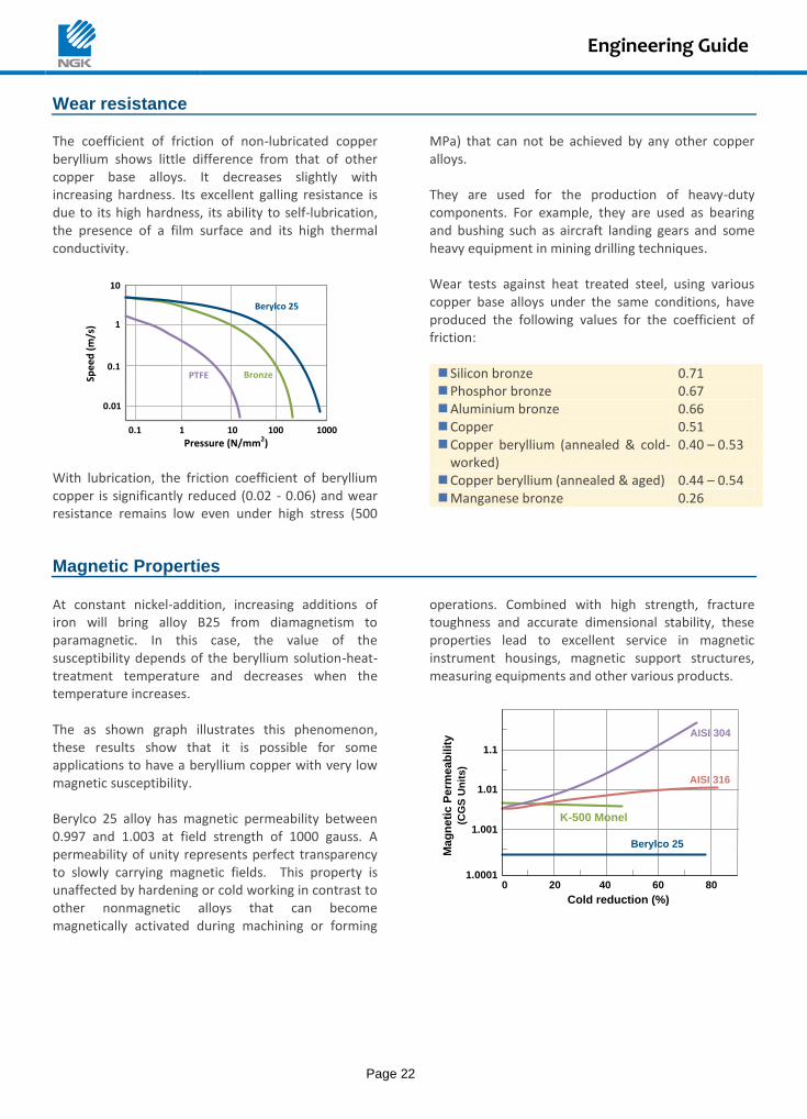
The coefficient of friction of non-lubricated copper beryllium shows little difference from that of other copper base alloys. It decreases slightly with increasing hardness. Its excellent galling resistance is due to its high hardness, its ability to self-lubrication, the presence of a film surface and its high thermal conductivity.
0.01
Pressure (N/mm2)
Spee
d (
m/s
)
Bronze
Berylco 25
0.1 1 10 100 1000
10
0.1
1
PTFE
With lubrication, the friction coefficient of beryllium copper is significantly reduced (0.02 - 0.06) and wear resistance remains low even under high stress (500
MPa) that can not be achieved by any other copper alloys. They are used for the production of heavy-duty components. For example, they are used as bearing and bushing such as aircraft landing gears and some heavy equipment in mining drilling techniques. Wear tests against heat treated steel, using various copper base alloys under the same conditions, have produced the following values for the coefficient of friction: Silicon bronze 0.71 Phosphor bronze 0.67 Aluminium bronze 0.66 Copper 0.51 Copper beryllium (annealed & cold-
worked) 0.40 – 0.53
Copper beryllium (annealed & aged) 0.44 – 0.54 Manganese bronze 0.26
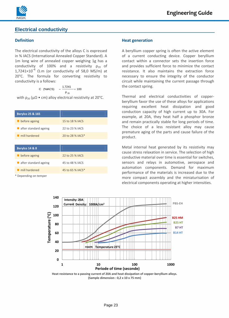
Magnetic Properties At constant nickel-addition, increasing additions of iron will bring alloy B25 from diamagnetism to paramagnetic. In this case, the value of the susceptibility depends of the beryllium solution-heat-treatment temperature and decreases when the temperature increases. The as shown graph illustrates this phenomenon, these results show that it is possible for some applications to have a beryllium copper with very low magnetic susceptibility. Berylco 25 alloy has magnetic permeability between 0.997 and 1.003 at field strength of 1000 gauss. A permeability of unity represents perfect transparency to slowly carrying magnetic fields. This property is unaffected by hardening or cold working in contrast to other nonmagnetic alloys that can become magnetically activated during machining or forming
operations. Combined with high strength, fracture toughness and accurate dimensional stability, these properties lead to excellent service in magnetic instrument housings, magnetic support structures, measuring equipments and other various products.
0 20 40 60 801.0001
1.001
1.01
1.1
Berylco 25
AISI 304
AISI 316
Cold reduction (%)
K-500 Monel
Ma
gn
eti
c P
erm
ea
bilit
y
(CG
S U
nit
s)
Engineering Guide
Page 23
Electrical conductivity
Definition The electrical conductivity of the alloys C is expressed in % IACS (International Annealed Copper Standard). A 1m long wire of annealed copper weighing 1g has a conductivity of 100% and a resistivity ρ20 of 1,7241×10
–8 Ω.m (or conductivity of 58,0 MS/m) at
20°C. The formula for converting resistivity to conductivity is a follows:
100ρ
1.7241(%IACS)C
20
with ρ20 (µΩ • cm) alloy electrical resistivity at 20°C.
Berylco 25 & 165
before ageing 15 to 18 % IACS
after standard ageing 22 to 23 % IACS
mill hardened 20 to 28 % IACS*
Berylco 14 & 8
before ageing 22 to 25 % IACS
after standard ageing 45 to 48 % IACS
mill hardened 45 to 65 % IACS*
* Depending on temper
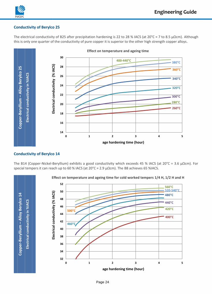
Heat generation A beryllium copper spring is often the active element of a current conducting device. Copper beryllium contact within a connector sets the insertion force and provides sufficient force to minimize the contact resistance. It also maintains the extraction force necessary to ensure the integrity of the conductor circuit while maintaining the current passage through the contact spring. Thermal and electrical conductivities of copper-beryllium favor the use of these alloys for applications requiring excellent heat dissipation and good conduction capacity of high current up to 30A. For example, at 20A, they heat half a phosphor bronze and remain practically stable for long periods of time. The choice of a less resistant alloy may cause premature aging of the parts and cause failure of the product. Metal internal heat generated by its resistivity may cause stress relaxation in service. The selection of high conductive material over time is essential for switches, sensors and relays in automotive, aerospace and automation components. Demand for maximum performance of the materials is increased due to the more compact assembly and the miniaturisation of electrical components operating at higher intensities.
Heat resistance to a passing current of 20A and heat dissipation of copper-beryllium alloys.
(Sample dimension : 0,2 x 10 x 75 mm)
Temperature 23°C room
B25 HM
B25 HT
B7 HT
B14 HT
PBS-EH Density: Current 1000A/cm2
Intensity: 20A
0
20
40
60
80
100
120
140
1 10 100 1000
Tem
per
atu
re (
°C)
Periode of time (seconde)
Engineering Guide
Page 24
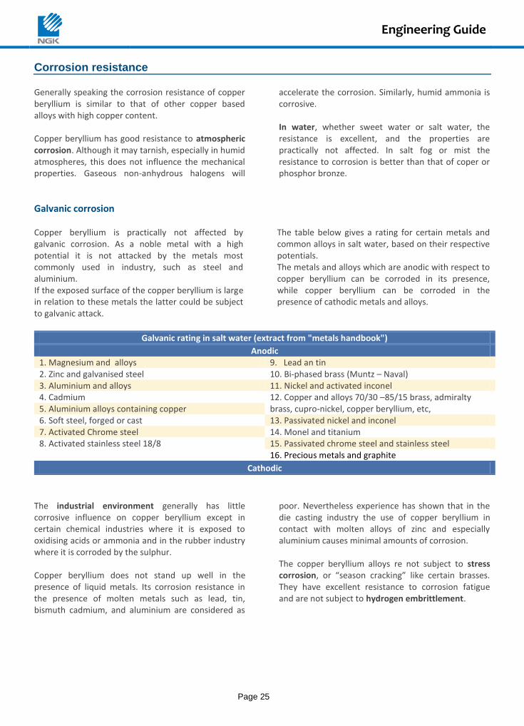
Conductivity of Berylco 25 The electrical conductivity of B25 after precipitation hardening is 22 to 28 % IACS (at 20°C = 7 to 8.5 μΩcm). Although this is only one quarter of the conductivity of pure copper it is superior to the other high strength copper alloys.
Co
pp
er-
Be
rylli
um
– A
lloy
Ber
ylco
25
Ele
ctri
cal c
on
du
ctiv
ity
in %
IAC
S
Effect on temperature and ageing time
Conductivity of Berylco 14 The B14 (Copper-Nickel-Beryllium) exhibits a good conductivity which exceeds 45 % IACS (at 20°C = 3.6 μΩcm). For special tempers it can reach up to 60 % IACS (at 20°C = 2.9 μΩcm). The B8 achieves 65 %IACS.
Co
pp
er-B
eryl
lium
– A
lloy
Ber
ylco
14
Ele
ctri
cal c
on
du
ctiv
ity
in %
IAC
S
Effect on temperature and ageing time for cold worked tempers 1/4 H, 1/2 H and H
320°C
340°C
280°C
300°C
260°C
400-440°C
360°C
380°C
14
16
18
20
22
24
26
28
30
0 1 2 3 4 5
Ele
ctri
cal c
on
du
ctiv
ity
(%
IAC
S)
age hardening time (hour)
460°C
480°C
420°C
440°C
400°C
560°C
500°C
520-540°C
32
34
36
38
40
42
44
46
48
50
52
0 1 2 3 4 5
Ele
ctri
cal c
on
du
ctiv
ity
(% IA
CS)
age hardening time (hour)
Engineering Guide
Page 25
Corrosion resistance Generally speaking the corrosion resistance of copper beryllium is similar to that of other copper based alloys with high copper content. Copper beryllium has good resistance to atmospheric corrosion. Although it may tarnish, especially in humid atmospheres, this does not influence the mechanical properties. Gaseous non-anhydrous halogens will
accelerate the corrosion. Similarly, humid ammonia is corrosive. In water, whether sweet water or salt water, the resistance is excellent, and the properties are practically not affected. In salt fog or mist the resistance to corrosion is better than that of coper or phosphor bronze.
Galvanic corrosion Copper beryllium is practically not affected by galvanic corrosion. As a noble metal with a high potential it is not attacked by the metals most commonly used in industry, such as steel and aluminium. If the exposed surface of the copper beryllium is large in relation to these metals the latter could be subject to galvanic attack.
The table below gives a rating for certain metals and common alloys in salt water, based on their respective potentials. The metals and alloys which are anodic with respect to copper beryllium can be corroded in its presence, while copper beryllium can be corroded in the presence of cathodic metals and alloys.
Galvanic rating in salt water (extract from "metals handbook")
Anodic 1. Magnesium and alloys 9. Lead an tin 2. Zinc and galvanised steel 10. Bi-phased brass (Muntz – Naval) 3. Aluminium and alloys 11. Nickel and activated inconel 4. Cadmium 12. Copper and alloys 70/30 –85/15 brass, admiralty 5. Aluminium alloys containing copper brass, cupro-nickel, copper beryllium, etc, 6. Soft steel, forged or cast 13. Passivated nickel and inconel 7. Activated Chrome steel 14. Monel and titanium 8. Activated stainless steel 18/8 15. Passivated chrome steel and stainless steel 16. Precious metals and graphite
Cathodic
The industrial environment generally has little corrosive influence on copper beryllium except in certain chemical industries where it is exposed to oxidising acids or ammonia and in the rubber industry where it is corroded by the sulphur. Copper beryllium does not stand up well in the presence of liquid metals. Its corrosion resistance in the presence of molten metals such as lead, tin, bismuth cadmium, and aluminium are considered as
poor. Nevertheless experience has shown that in the die casting industry the use of copper beryllium in contact with molten alloys of zinc and especially aluminium causes minimal amounts of corrosion. The copper beryllium alloys re not subject to stress corrosion, or “season cracking” like certain brasses. They have excellent resistance to corrosion fatigue and are not subject to hydrogen embrittlement.
Engineering Guide
Page 26
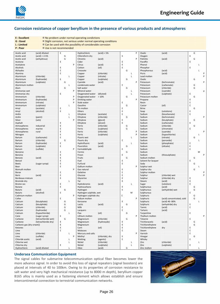
Corrosion resistance of copper beryllium in the presence of various products and atmospheres E : Excellent No problem under normal operating condictions G : Good Slight corrosion, not serious under normal operating conditions L : Limited Can be used with the possibility of considerable corrosion P : Poor Use is not recommended
Acetic acid (acid) diluted E Hydrochloric (acid) > 5% P Oxalic (acid) G Acetic acid (acid) > 2.5% G Chloroform dry E Oxygen E Acetic acid (anhydrous) G Chromic (acid) P Palmitic (acid) G Acetone E Cider E Paraffin E Acetylene P Citrus (acid) E Phenol L Alcohols E Cotton (oil) E Phosphor E Alchydes E Creosote G Phosphorous (acid) L Alumina E Copper (chloride) L Picric (acid) P Aluminium (chloride) L Copper (nitrate) L Lead molten P Aluminium (hydroxide) E Copper (sulphate) G Oxalic G Aluminium (sulphate) G Cyanide (acid) P Potassium (bichromate) P Aluminium molten L condensate water E Potassium (carbonate) G Alum G Salt water G Potassium (chloride) G Ammoniac wet P Mineral water L Potassium (cyanide) p Ammoniac dry E Oxygenated water (diluted) L Potassium (sulphate) E Ammonium (chloride) P Oxygenated water > 10% G Potassium molten G Ammonium (hydroxide) P Drinking water P Propane E Ammonium (nitrate) P Stale water E Resin E Ammonium (sulphate) L Gasoline G Castor (oil) E Amyl (acetate) E Tin molten E Brine G Amyl (alcohol) E Ethers E Soap (solutions) E Anilin L Ethylene (acetate) E Sodium (bicarbonate) E Anilin (paint) L Ethylene (chloride) G Sodium (bichromate) P Silver (sels) P Ethylene (glycol) E Sodium (bisulphate) G Asphalt E Ethylene (alcool) E Sodium (carbonate) E Atmospheres industrial E Ferric (chloride) G Sodium (chloride) G Atmospheres marine E Ferric (sulphate) G Sodium (chromate) E Atmospheres rural E Ferric (chloride) P Sodium (cyanide) P Nitrogen E Ferric (sulphate) P Sodium (hypochlorite) L Barium (carbonate) E Fluoric wet L Sodium (nitrate) G Barium (chloride) G Fluoric dry E Sodium (peroxide) L Barium (hydroxide) E Hydrofluoric (acid) L Sodium (phosphate) E Barium (sulphate) E Fluorsilicic (acid) G Sodium (silicate) E Barium (sulfide) P Formaldehyde E Sodium E Benzene E Formic G Sodium M Benzine E Freon E Sodium (thiosulphate) P Benzoic (acid) E Fruits (juice) G Sodium molten G Benzol E Fuel E Solvent for lacquer E Beets (sugar syrop) E Furfural E Soda G Beer E Gallium molten P Sulphur wet L Bismuth molten P Gas natural E Sulphur dry G Borax E Gelatine E Sulphur molten P Boric (acid) E Glucose E Sulphur (chloride) wet P Bordeaux mixture E Glycerine E Sulphur (chloride) dry E Bromide dry L Tar E Stearic (acid) E Brome sec E Hydrobromic (acid) L Sugar (solution) E Butane E Hydrocarbons E Sulphurous (acid) G Butyric (acid) G Hydrogen E Sulphurous (anhydride) wet G Butyric (alcohol) E Hydrogen sulphide, wet M Sulphurous E Cadmium molten P Hydrogen sulphide dry E Sulphuric G Cofee E Indium molten P Sulphuric (acid) concentrated, cold G Calcium (bisulphate) G Kerosene E Sulphuric (acid) 40- 80% L Calcium (bisulphide) G Lactic (acid) G Sulphuric (anhydride) dry E Calcium (chloride) G Milk E Tannic (acid) E Calcium (hydroxide) G Lacquers E Tartaric (acid) Calcium (hypochloride) L Flax (oil) G Turpentine E Cane (sugar syrop) E Lithium molten P Thallium molten P Carbone (tetrachloride wet) G Magnesium (chloride) G Toluene E Carbone (tetrachloride dry) E Magnesium (hydroxyde) E Trichloracetic (acid) G Carbonic gas (dry orwet)) E Magnesium E Trichlorethylene G Ketones E Corn (oil) E Trichlorethylene dry E Lime E Molasses E Steam E Lime (chloride) L Mercury and salts P Varnish E Lime (sulfide) P Methyl (chloride), dry E Vinegar G Chloride acetic (acid) L Wetting (agents) E Whisky E Chlorine wet L Nickel (chloride) L Zinc (chloride) L Chlorine dry E Nickel (sulphate) L Zinc (sulphate) E Hydrochloric (acid) diluted L Oleic (acid) G Zinc molten L
Undersea Communication Equipment The signal cables for submarine telecommunication optical fiber becomes lower the more advance signal. In order to avoid this loss of signal repeaters (signal boosters) are placed at intervals of 40 to 100km. Owing to its properties of corrosion resistance to salt water and very high mechanical resistance (up to 8000 m depth), beryllium copper B165 alloy is mainly used as a fastening element which allows establish and ensure intercontinental connection to terrestrial communication networks.
Manufacturing Technology
Page 27
Stamping and Forming
Stamping
Beryllium copper in the cold-worked condition exhibits sharper cuts and less burrs than in the ageing temper. A clearance between punch and die of 5-10 % of the material thickness should be used. If solution annealed material has to be used the clearance should be reduced to 5-6 % to avoid excessive wear of the tooling. If the strip has been stored for an extended period of time in a potentially oxidising atmosphere, like high humidity, it should be pickled prior to stamping.
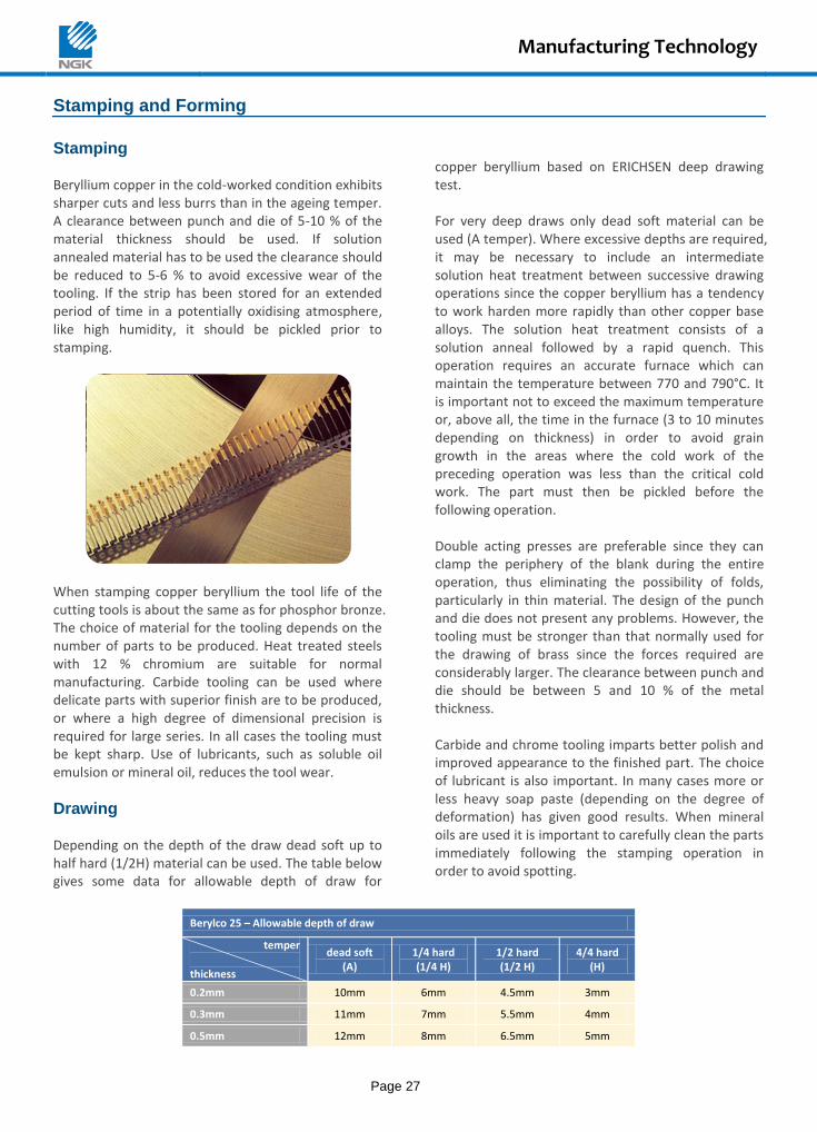
When stamping copper beryllium the tool life of the cutting tools is about the same as for phosphor bronze. The choice of material for the tooling depends on the number of parts to be produced. Heat treated steels with 12 % chromium are suitable for normal manufacturing. Carbide tooling can be used where delicate parts with superior finish are to be produced, or where a high degree of dimensional precision is required for large series. In all cases the tooling must be kept sharp. Use of lubricants, such as soluble oil emulsion or mineral oil, reduces the tool wear.
Drawing Depending on the depth of the draw dead soft up to half hard (1/2H) material can be used. The table below gives some data for allowable depth of draw for
copper beryllium based on ERICHSEN deep drawing test. For very deep draws only dead soft material can be used (A temper). Where excessive depths are required, it may be necessary to include an intermediate solution heat treatment between successive drawing operations since the copper beryllium has a tendency to work harden more rapidly than other copper base alloys. The solution heat treatment consists of a solution anneal followed by a rapid quench. This operation requires an accurate furnace which can maintain the temperature between 770 and 790°C. It is important not to exceed the maximum temperature or, above all, the time in the furnace (3 to 10 minutes depending on thickness) in order to avoid grain growth in the areas where the cold work of the preceding operation was less than the critical cold work. The part must then be pickled before the following operation. Double acting presses are preferable since they can clamp the periphery of the blank during the entire operation, thus eliminating the possibility of folds, particularly in thin material. The design of the punch and die does not present any problems. However, the tooling must be stronger than that normally used for the drawing of brass since the forces required are considerably larger. The clearance between punch and die should be between 5 and 10 % of the metal thickness. Carbide and chrome tooling imparts better polish and improved appearance to the finished part. The choice of lubricant is also important. In many cases more or less heavy soap paste (depending on the degree of deformation) has given good results. When mineral oils are used it is important to carefully clean the parts immediately following the stamping operation in order to avoid spotting.
Berylco 25 – Allowable depth of draw
temper
thickness
dead soft (A)
1/4 hard (1/4 H)
1/2 hard (1/2 H)
4/4 hard (H)
0.2mm 10mm 6mm 4.5mm 3mm
0.3mm 11mm 7mm 5.5mm 4mm
0.5mm 12mm 8mm 6.5mm 5mm
Manufacturing Technology
Page 28
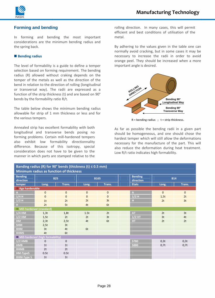
Forming and bending In forming and bending the most important considerations are the minimum bending radius and the spring back. Bending radius The level of formability is a guide to define a temper selection based on forming requirement. The bending radius (R) allowed without craking depends on the temper of the metals as well as the direction of the bend in relation to the direction of rolling (longitudinal or transversal way). The radii are expressed as a function of the strip thickness (t) and are based on 90° bends by the formability ratio R/t. The table below shows the minimum bending radius allowable for strip of 1 mm thickness or less and for the various tempers. Annealed strip has excellent formability with both longitudinal and transverse bends posing no forming problems. Certain mill-hardened tempers also exhibit low formability directionnality difference. Because of this isotropy, special consideration does not have to be given to the manner in which parts are stamped relative to the
rolling direction. In many cases, this will permit efficient and best conditions of utilisation of the metal. By adhering to the values given in the table one can normally avoid cracking, but in some cases it may be necessary to increase the radii in order to avoid orange peel. They should be increased when a more important angle is desired.
ROLLING
DIRECTIO
N
Bending 90°
Transverse Way
Bending 90°
Longitudinal Way
R = bending radius ; t = strip thickness.
As far as possible the bending radii in a given part should be homogeneous, and one should chose the hardest temper which will still allow the deformations necessary for the manufacture of the part. This will also reduce the deformation during heat treatment. Low R/t ratio indicates high formability.
Banding radius (R) for 90° bends (thickness (t) ≤ 0.5 mm) Minimum radius as function of thickness
Bending direction
B25 B165 Bending direction
B14
temper Long. Trans. Long. Trans. Etats Long. Trans.
Age hardenable
A 0 0 0 0 A 0 0
1/4 H 0 0 0 0 1/2 H 1,5t 2t
1/2 H 1t 2t 2t 3t H 2t 3t
H 2t 5t 4t 6t
Mill-hardened (standard)
1/4 HM 1,3t 1,8t 1.5t 2t AT 2t 3t
1/2 HM 1,5t 2t 2t 3t 1/2 HT 3t 4t
HM 2,3t 2,5t 4t 6t HT 2t 2t
SHM 2,5t 3t
XHM 3t 4t 6t
XHMS 4t 6t
Mill-hardened (high formability)
1/2 HMB 0 0 S780 0,3t 0,3t
HMB 1t 1t S880 0,7t 0,7t
XHMB 2t 2t
HM-TypeS 0.5t 0.5t
XHM-Type S 1t 1t
Manufacturing Technology
Page 29
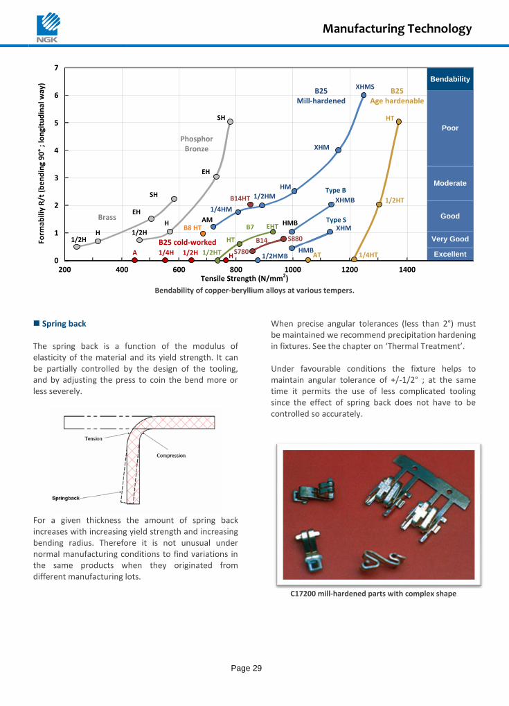
Bendability
Excellent
Very Good
Good
Moderate
Poor
0
1
2
3
4
5
6
7
200 400 600 800 1000 1200 1400Tensile Strength (N/mm2)
Form
abili
y R
/t (
be
nd
ing
90
° ;
lon
gitu
din
al w
ay)
1/4HTAT1/2HMB
1/2H
1/2HT HMBS780
1/2HT
HT
XHMB
HMBEHT
HT
SH
EH
1/2HM
HM
1/4HM
H
H
EH
SH
PhosphorBronze
Brass AM
B14HTType B
XHMS
XHM
B14
XHMType S
B7
S880
B25Age hardenable
B25Mill-hardened
1/2H
B8 HT
1/4HA 1/2H H
B25 cold-worked
Bendability of copper-beryllium alloys at various tempers.
Spring back The spring back is a function of the modulus of elasticity of the material and its yield strength. It can be partially controlled by the design of the tooling, and by adjusting the press to coin the bend more or less severely.
For a given thickness the amount of spring back increases with increasing yield strength and increasing bending radius. Therefore it is not unusual under normal manufacturing conditions to find variations in the same products when they originated from different manufacturing lots.
When precise angular tolerances (less than 2°) must be maintained we recommend precipitation hardening in fixtures. See the chapter on ‘Thermal Treatment’. Under favourable conditions the fixture helps to maintain angular tolerance of +/-1/2° ; at the same time it permits the use of less complicated tooling since the effect of spring back does not have to be controlled so accurately.
C17200 mill-hardened parts with complex shape
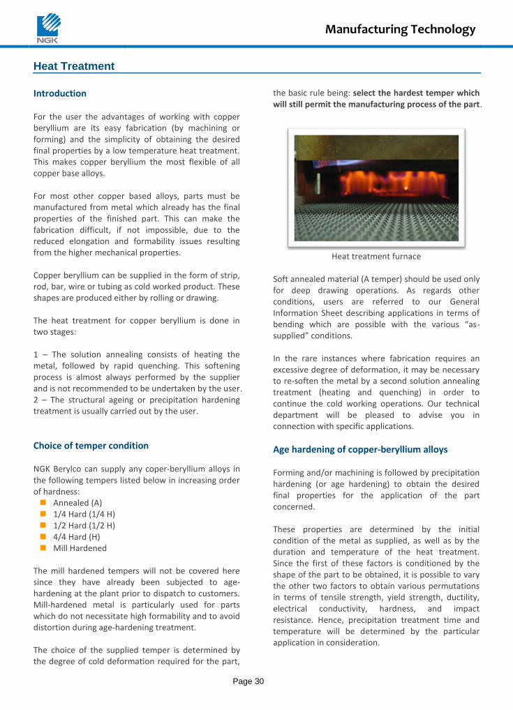
Manufacturing Technology
Page 30
Heat Treatment
Introduction For the user the advantages of working with copper beryllium are its easy fabrication (by machining or forming) and the simplicity of obtaining the desired final properties by a low temperature heat treatment. This makes copper beryllium the most flexible of all copper base alloys. For most other copper based alloys, parts must be manufactured from metal which already has the final properties of the finished part. This can make the fabrication difficult, if not impossible, due to the reduced elongation and formability issues resulting from the higher mechanical properties. Copper beryllium can be supplied in the form of strip, rod, bar, wire or tubing as cold worked product. These shapes are produced either by rolling or drawing. The heat treatment for copper beryllium is done in two stages: 1 – The solution annealing consists of heating the metal, followed by rapid quenching. This softening process is almost always performed by the supplier and is not recommended to be undertaken by the user. 2 – The structural ageing or precipitation hardening treatment is usually carried out by the user.
Choice of temper condition NGK Berylco can supply any coper-beryllium alloys in the following tempers listed below in increasing order of hardness: Annealed (A) 1/4 Hard (1/4 H) 1/2 Hard (1/2 H) 4/4 Hard (H) Mill Hardened
The mill hardened tempers will not be covered here since they have already been subjected to age-hardening at the plant prior to dispatch to customers. Mill-hardened metal is particularly used for parts which do not necessitate high formability and to avoid distortion during age-hardening treatment. The choice of the supplied temper is determined by the degree of cold deformation required for the part,
the basic rule being: select the hardest temper which will still permit the manufacturing process of the part.
Heat treatment furnace
Soft annealed material (A temper) should be used only for deep drawing operations. As regards other conditions, users are referred to our General Information Sheet describing applications in terms of bending which are possible with the various “as-supplied” conditions. In the rare instances where fabrication requires an excessive degree of deformation, it may be necessary to re-soften the metal by a second solution annealing treatment (heating and quenching) in order to continue the cold working operations. Our technical department will be pleased to advise you in connection with specific applications.
Age hardening of copper-beryllium alloys Forming and/or machining is followed by precipitation hardening (or age hardening) to obtain the desired final properties for the application of the part concerned. These properties are determined by the initial condition of the metal as supplied, as well as by the duration and temperature of the heat treatment. Since the first of these factors is conditioned by the shape of the part to be obtained, it is possible to vary the other two factors to obtain various permutations in terms of tensile strength, yield strength, ductility, electrical conductivity, hardness, and impact resistance. Hence, precipitation treatment time and temperature will be determined by the particular application in consideration.
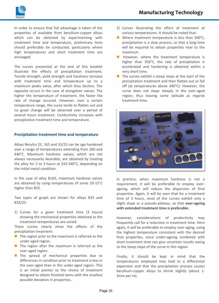
Manufacturing Technology
Page 31
In order to ensure that full advantage is taken of the properties of available from beryllium-copper alloys which can be obtained by experimenting with treatment time and temperature, preliminary tests should preferably be conducted, particularly where high temperatures and short treatment time are envisaged. The curves presented at the end of this booklet illustrate the effects of precipitation treatment. Tensile strength, yield strength and hardness increase with treatment time and temperature up to a maximum peaks value, after which they decline. The opposite occurs in the case of elongation values. The higher the temperature of treatment, the faster the rate of change occured. However, over a certain temperature range, the curve tends to flatten out and no great change will be observed over a period of several hours treatment. Conductivity increases with precipitation treatment time and temperature.
Precipitation treatment time and temperature Alloys Berylco 25, 165 and 33/25 can be age hardened over a range of temperatures extending from 260 and 440°C. Maximum hardness values, which are not always necessarily desirable, are obtained by treating the alloy for 2 to 3 hours at 310-340°C, depending on the initial metal condition. In the case of alloy B165, maximum hardness values are obtained by using temperatures of some 10-15°C higher than B25. Two types of graph are shown for alloys B25 and B33/25: 1) Curves for a given treatment time (3 hours)
showing the mechanical properties obtained as the treatment temperatures are varied.
These curves clearly show the effects of the precipitation treatment: The region prior to the maximum is referred as the
under-aged region. The region after the maximum is referred as the
over-aged region. The spread of mechanical properties due to
differences in condition prior to treatment is less in the over-aged than in the under-aged region. This is an initial pointer to the choice of treatment designed to obtain finished items with the smallest possible deviation in properties..
2) Curves illustrating the effect of treatment at various temperatures. It should be noted that:
Where treatment temperature is less than 300°C, precipitation is a slow process, so that a long time will be required to obtain properties near to the maximum.
However, where the treatment temperature is higher than 350°C, the rate of precipitation is accelerated and hardening is obtained within a very short time.
The curves exhibit a steep slope at the start of the precipitation treatment and then flatten out or fall off (at temperatures above 340°C). However, the curve does not slope steeply in the over-aged region, thus leaving some latitude as regards treatment time.
In practice, when maximum hardness is not a requirement, it will be preferable to employ over-ageing, which will reduce the dispersion of final properties. Again, it will be seen that for a treatment time of 3 hours, most of the curves exhibit only a slight slope or a pseudo-plateau, so that over-ageing with extended treatment time is preferable. However, considerations of productivity may frequently call for a reduction in treatment time. Here again, it will be preferable to employ over-aging, using the highest temperature consistent with the desired final properties, since under-ageing combined with short treatment time can give uncertain results owing to the steep slope of the curve in this region. Finally, it should be kept in mind that the temperatures employed may lead to a differential expansion and that the precipitation process causes beryllium-copper alloys to shrink slightly (about 1-3mm per m).
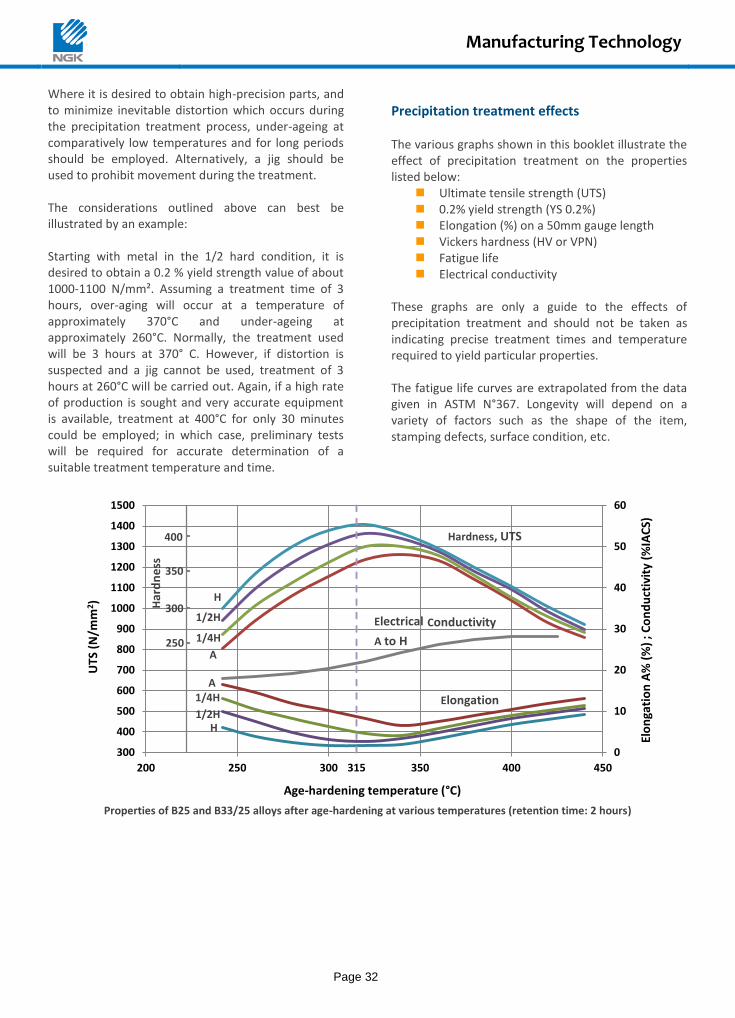
Manufacturing Technology
Page 32
Where it is desired to obtain high-precision parts, and to minimize inevitable distortion which occurs during the precipitation treatment process, under-ageing at comparatively low temperatures and for long periods should be employed. Alternatively, a jig should be used to prohibit movement during the treatment. The considerations outlined above can best be illustrated by an example: Starting with metal in the 1/2 hard condition, it is desired to obtain a 0.2 % yield strength value of about 1000-1100 N/mm². Assuming a treatment time of 3 hours, over-aging will occur at a temperature of approximately 370°C and under-ageing at approximately 260°C. Normally, the treatment used will be 3 hours at 370° C. However, if distortion is suspected and a jig cannot be used, treatment of 3 hours at 260°C will be carried out. Again, if a high rate of production is sought and very accurate equipment is available, treatment at 400°C for only 30 minutes could be employed; in which case, preliminary tests will be required for accurate determination of a suitable treatment temperature and time.
Precipitation treatment effects The various graphs shown in this booklet illustrate the effect of precipitation treatment on the properties listed below:
Ultimate tensile strength (UTS) 0.2% yield strength (YS 0.2%) Elongation (%) on a 50mm gauge length Vickers hardness (HV or VPN) Fatigue life Electrical conductivity
These graphs are only a guide to the effects of precipitation treatment and should not be taken as indicating precise treatment times and temperature required to yield particular properties. The fatigue life curves are extrapolated from the data given in ASTM N°367. Longevity will depend on a variety of factors such as the shape of the item, stamping defects, surface condition, etc.
Properties of B25 and B33/25 alloys after age-hardening at various temperatures (retention time: 2 hours)
400
H
1/2H
1/4H
A
A 1/4H
1/2H H
Hardness, UTS
250
Har
dn
ess
Conductivity
A to H
Electrical 300
350
315
Elongation
0
10
20
30
40
50
60
300
400
500
600
700
800
900
1000
1100
1200
1300
1400
1500
200 250 300 350 400 450
Elo
nga
tio
n A
% (
%)
; C
on
du
ctiv
ity
(%IA
CS)
UTS
(N
/mm
2 )
Age-hardening temperature (°C)
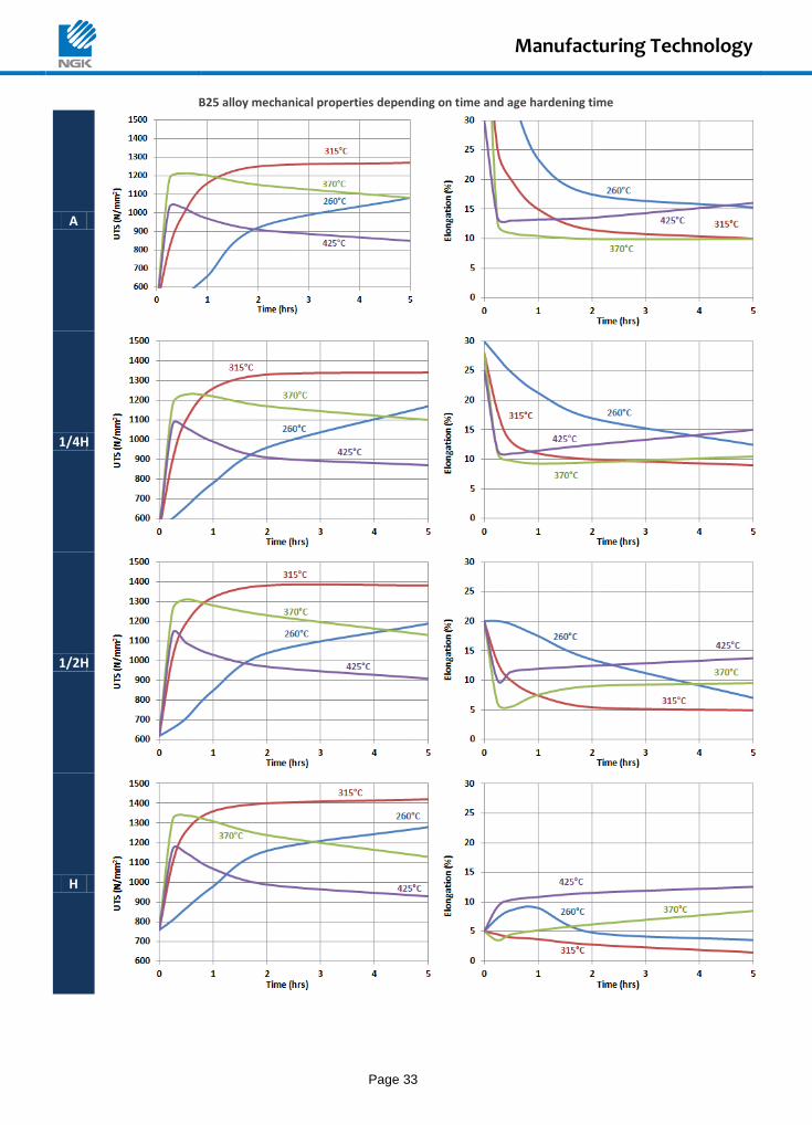
Manufacturing Technology
Page 33
B25 alloy mechanical properties depending on time and age hardening time
A
1/4H
1/2H
H
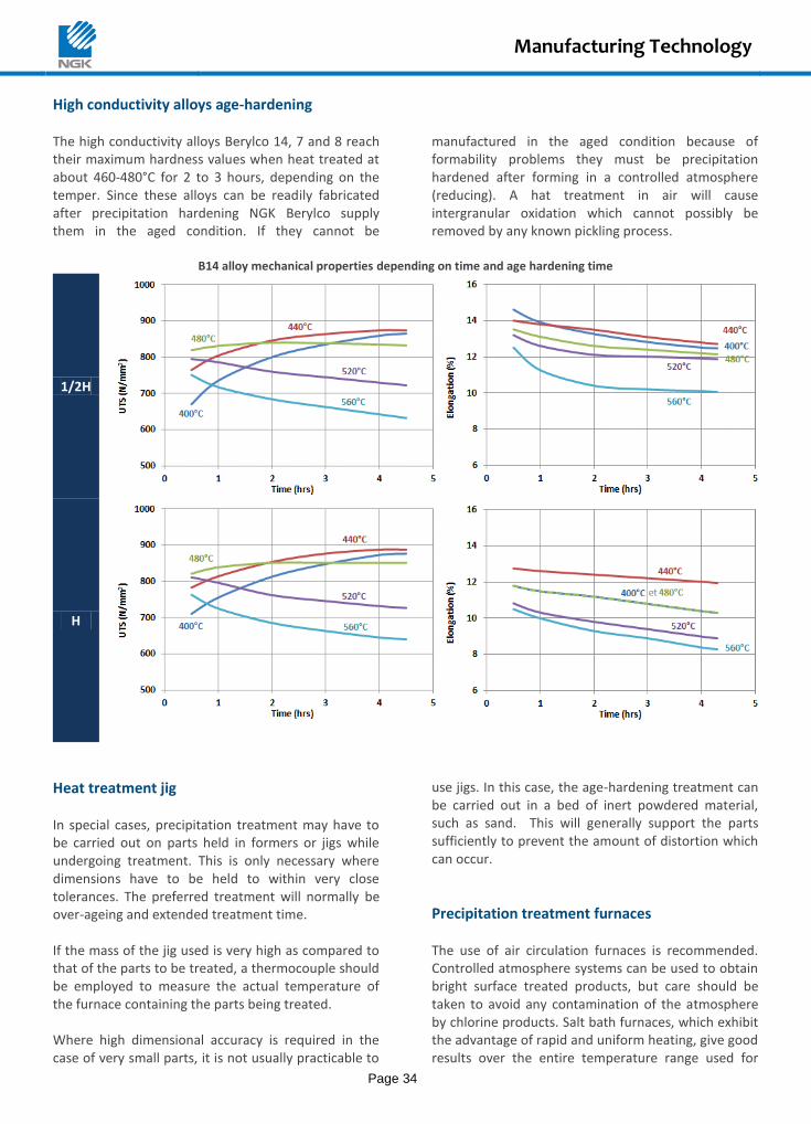
Manufacturing Technology
Page 34
High conductivity alloys age-hardening The high conductivity alloys Berylco 14, 7 and 8 reach their maximum hardness values when heat treated at about 460-480°C for 2 to 3 hours, depending on the temper. Since these alloys can be readily fabricated after precipitation hardening NGK Berylco supply them in the aged condition. If they cannot be
manufactured in the aged condition because of formability problems they must be precipitation hardened after forming in a controlled atmosphere (reducing). A hat treatment in air will cause intergranular oxidation which cannot possibly be removed by any known pickling process.
B14 alloy mechanical properties depending on time and age hardening time
1/2H
H
Heat treatment jig In special cases, precipitation treatment may have to be carried out on parts held in formers or jigs while undergoing treatment. This is only necessary where dimensions have to be held to within very close tolerances. The preferred treatment will normally be over-ageing and extended treatment time. If the mass of the jig used is very high as compared to that of the parts to be treated, a thermocouple should be employed to measure the actual temperature of the furnace containing the parts being treated. Where high dimensional accuracy is required in the case of very small parts, it is not usually practicable to
use jigs. In this case, the age-hardening treatment can be carried out in a bed of inert powdered material, such as sand. This will generally support the parts sufficiently to prevent the amount of distortion which can occur.
Precipitation treatment furnaces The use of air circulation furnaces is recommended. Controlled atmosphere systems can be used to obtain bright surface treated products, but care should be taken to avoid any contamination of the atmosphere by chlorine products. Salt bath furnaces, which exhibit the advantage of rapid and uniform heating, give good results over the entire temperature range used for
Manufacturing Technology
Page 35
precipitation treatment of beryllium-copper. They can be beneficial, where the treatment time is short and where a precise means of controlling temperature is required. Commercially available salt mixtures with melting points in a range 135-220°C are normally used. Nitrate-based salts dissolve readily in hot water, but require the observance of certain precautions as specified by the suppliers. Air or controlled atmosphere furnaces which do not provide circulation can only be used for quite long treatment times of about 3 hours. The use of vacuum furnaces is not recommended because of the low rate of heat exchange obtained with this type of furnace. Since the rate of cooling is not critical, parts leaving the treatment furnace can be quenched in cold water, thus simplifying handling and setting a definite limit to the treatment time employed.
Cleaning –pickling and brightening Where the precipitation treatment is not carried out in a controlled atmosphere and it is desired to obtain a clean surface and bright finish after heat treatment, a number of precautions and finishing operations will be required. All parts to be treated should be absolutely free of grease. Should this not be the case, parts should be carefully degreased. Parts should be pickled after heat treatment. A simple method consists of immersing the parts in a 20-30 %
sulphuric acid bath used at 80-90°C. The parts should be pickled for 15-30 minutes, depending on the degree of oxidation (or until the dark film on the surface has been removed). The pickling operation should be followed by rinsing in cold water. Pickling may be followed by brightening. However, when brightening treatment is to be employed, extra care has to be taken with pickling, otherwise dull or pitted areas may persist after brightening. The maximum permissible pickling time can be determined by noting the subsequent results obtained on brightening. A variety of brightening processes exist, some of which merely restore the original color of the metal, two examples are: Immersion in a cold 15-30 % nitric acid and water
solution. The parts should be withdrawn as soon as gas bubbles appear..
Immersion for 30-45 seconds in a cold 2.5 % (in volume) sulphuric acid solution to which has been added 50-60 g/litre of sodium bichromate.
In both the above cases, the brightening stage should be followed by thorough rinsing in cold water and drying. Other brightening baths, such as “White” baths (sulphuric/nitric acid mixtures at various concentrations) give better results, but require some skill and experience in their operation in view of the possible rate of attack on the metal. The bichromate bath is not recommended where brightening is to be followed by electroplating.
Machining
Copper beryllium alloys can be machined at any conditions. The machining properties of the copper beryllium alloys depend largely on their composition and temper. The accompanying table gives machinability ratings compared to free-machining brass, which is rated 100. Based on this comparison a material with an index of 50 should be machined at a speed of approximately half of that used for a material rated 100 in order to obtain the same tool life.
These values can only be used as a guide since the machinability depends on a number of factors such as the type of machine, type of tool used, experience of the operator, rigidity of the support, etc. For copper beryllium, however, there are a number of points which must be kept in mind: This alloy work hardens very rapidly and each cut
must penetrate below the surface which has been work hardened by the preceding cut; for practical purposes a depth of 0.2 mm is considered a minimum.
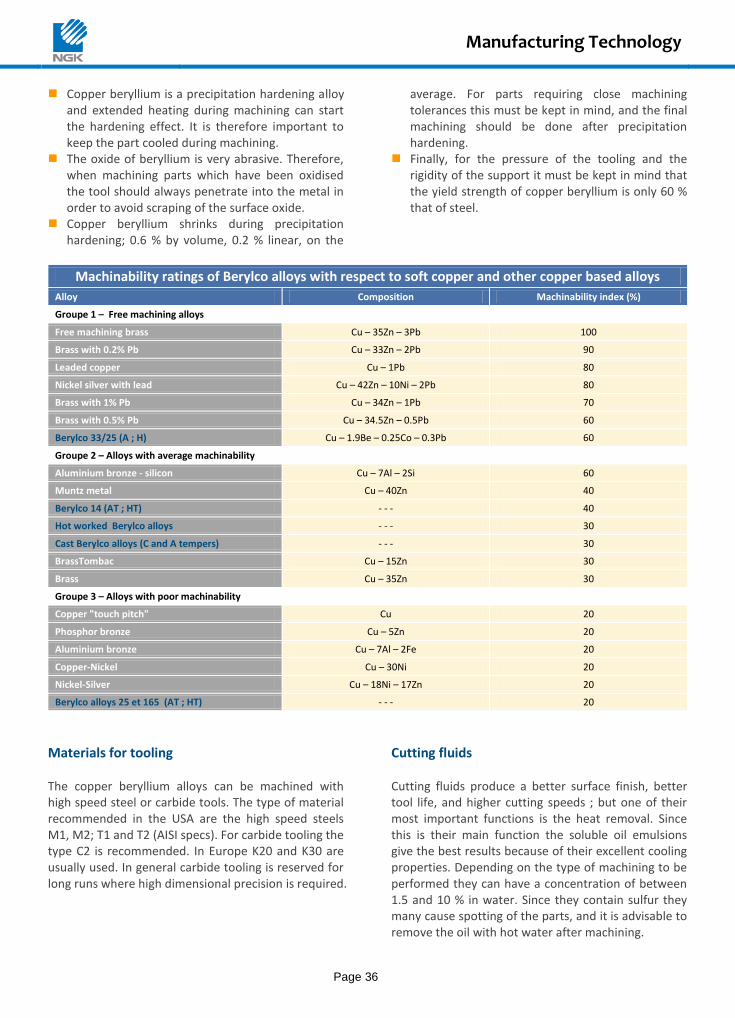
Manufacturing Technology
Page 36
Copper beryllium is a precipitation hardening alloy and extended heating during machining can start the hardening effect. It is therefore important to keep the part cooled during machining.
The oxide of beryllium is very abrasive. Therefore, when machining parts which have been oxidised the tool should always penetrate into the metal in order to avoid scraping of the surface oxide.
Copper beryllium shrinks during precipitation hardening; 0.6 % by volume, 0.2 % linear, on the
average. For parts requiring close machining tolerances this must be kept in mind, and the final machining should be done after precipitation hardening.
Finally, for the pressure of the tooling and the rigidity of the support it must be kept in mind that the yield strength of copper beryllium is only 60 % that of steel.
Machinability ratings of Berylco alloys with respect to soft copper and other copper based alloys Alloy Composition Machinability index (%)
Groupe 1 – Free machining alloys
Free machining brass Cu – 35Zn – 3Pb 100
Brass with 0.2% Pb Cu – 33Zn – 2Pb 90
Leaded copper Cu – 1Pb 80
Nickel silver with lead Cu – 42Zn – 10Ni – 2Pb 80
Brass with 1% Pb Cu – 34Zn – 1Pb 70
Brass with 0.5% Pb Cu – 34.5Zn – 0.5Pb 60
Berylco 33/25 (A ; H) Cu – 1.9Be – 0.25Co – 0.3Pb 60
Groupe 2 – Alloys with average machinability
Aluminium bronze - silicon Cu – 7Al – 2Si 60
Muntz metal Cu – 40Zn 40
Berylco 14 (AT ; HT) - - - 40
Hot worked Berylco alloys - - - 30
Cast Berylco alloys (C and A tempers) - - - 30
BrassTombac Cu – 15Zn 30
Brass Cu – 35Zn 30
Groupe 3 – Alloys with poor machinability
Copper "touch pitch" Cu 20
Phosphor bronze Cu – 5Zn 20
Aluminium bronze Cu – 7Al – 2Fe 20
Copper-Nickel Cu – 30Ni 20
Nickel-Silver Cu – 18Ni – 17Zn 20
Berylco alloys 25 et 165 (AT ; HT) - - - 20
Materials for tooling The copper beryllium alloys can be machined with high speed steel or carbide tools. The type of material recommended in the USA are the high speed steels M1, M2; T1 and T2 (AISI specs). For carbide tooling the type C2 is recommended. In Europe K20 and K30 are usually used. In general carbide tooling is reserved for long runs where high dimensional precision is required.
Cutting fluids Cutting fluids produce a better surface finish, better tool life, and higher cutting speeds ; but one of their most important functions is the heat removal. Since this is their main function the soluble oil emulsions give the best results because of their excellent cooling properties. Depending on the type of machining to be performed they can have a concentration of between 1.5 and 10 % in water. Since they contain sulfur they many cause spotting of the parts, and it is advisable to remove the oil with hot water after machining.
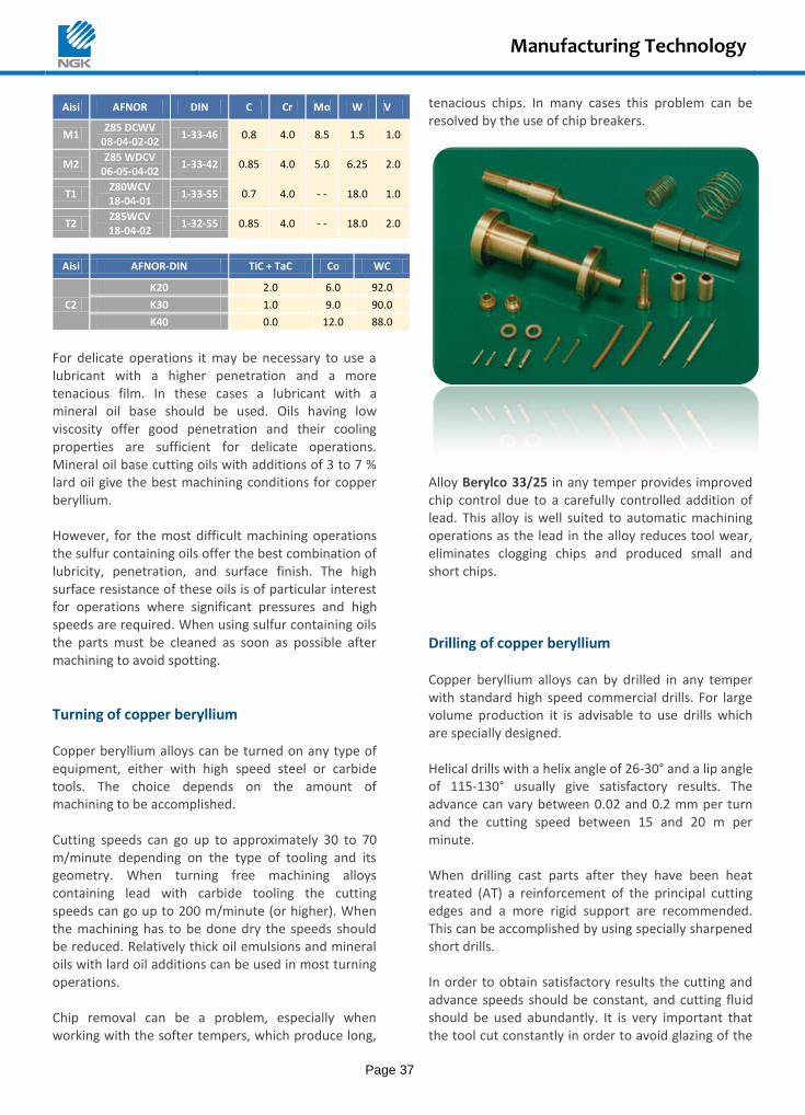
Manufacturing Technology
Page 37
Aisi AFNOR DIN C Cr Mo W V
M1 Z85 DCWV
08-04-02-02 1-33-46 0.8 4.0 8.5 1.5 1.0
M2 Z85 WDCV
06-05-04-02 1-33-42 0.85 4.0 5.0 6.25 2.0
T1 Z80WCV 18-04-01
1-33-55 0.7 4.0 - - 18.0 1.0
T2 Z85WCV 18-04-02
1-32-55 0.85 4.0 - - 18.0 2.0
Aisi AFNOR-DIN TiC + TaC Co WC
C2
K20 2.0 6.0 92.0
K30 1.0 9.0 90.0
K40 0.0 12.0 88.0
For delicate operations it may be necessary to use a lubricant with a higher penetration and a more tenacious film. In these cases a lubricant with a mineral oil base should be used. Oils having low viscosity offer good penetration and their cooling properties are sufficient for delicate operations. Mineral oil base cutting oils with additions of 3 to 7 % lard oil give the best machining conditions for copper beryllium. However, for the most difficult machining operations the sulfur containing oils offer the best combination of lubricity, penetration, and surface finish. The high surface resistance of these oils is of particular interest for operations where significant pressures and high speeds are required. When using sulfur containing oils the parts must be cleaned as soon as possible after machining to avoid spotting.
Turning of copper beryllium Copper beryllium alloys can be turned on any type of equipment, either with high speed steel or carbide tools. The choice depends on the amount of machining to be accomplished. Cutting speeds can go up to approximately 30 to 70 m/minute depending on the type of tooling and its geometry. When turning free machining alloys containing lead with carbide tooling the cutting speeds can go up to 200 m/minute (or higher). When the machining has to be done dry the speeds should be reduced. Relatively thick oil emulsions and mineral oils with lard oil additions can be used in most turning operations. Chip removal can be a problem, especially when working with the softer tempers, which produce long,
tenacious chips. In many cases this problem can be resolved by the use of chip breakers.
Alloy Berylco 33/25 in any temper provides improved chip control due to a carefully controlled addition of lead. This alloy is well suited to automatic machining operations as the lead in the alloy reduces tool wear, eliminates clogging chips and produced small and short chips.
Drilling of copper beryllium Copper beryllium alloys can by drilled in any temper with standard high speed commercial drills. For large volume production it is advisable to use drills which are specially designed. Helical drills with a helix angle of 26-30° and a lip angle of 115-130° usually give satisfactory results. The advance can vary between 0.02 and 0.2 mm per turn and the cutting speed between 15 and 20 m per minute. When drilling cast parts after they have been heat treated (AT) a reinforcement of the principal cutting edges and a more rigid support are recommended. This can be accomplished by using specially sharpened short drills. In order to obtain satisfactory results the cutting and advance speeds should be constant, and cutting fluid should be used abundantly. It is very important that the tool cut constantly in order to avoid glazing of the
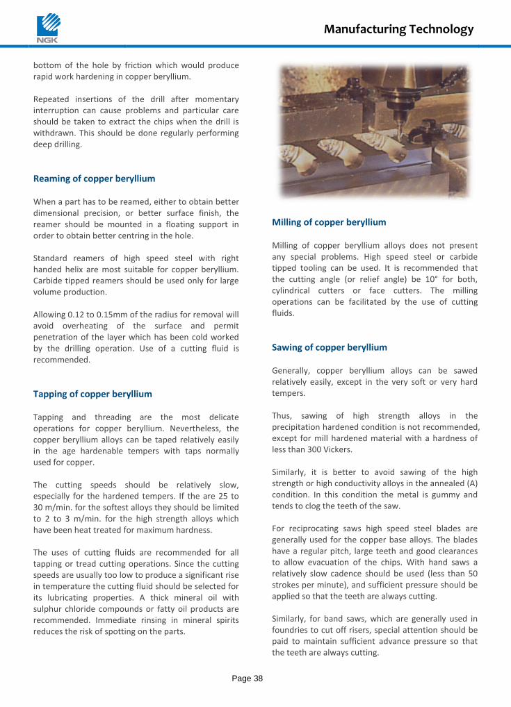
Manufacturing Technology
Page 38
bottom of the hole by friction which would produce rapid work hardening in copper beryllium. Repeated insertions of the drill after momentary interruption can cause problems and particular care should be taken to extract the chips when the drill is withdrawn. This should be done regularly performing deep drilling.
Reaming of copper beryllium When a part has to be reamed, either to obtain better dimensional precision, or better surface finish, the reamer should be mounted in a floating support in order to obtain better centring in the hole. Standard reamers of high speed steel with right handed helix are most suitable for copper beryllium. Carbide tipped reamers should be used only for large volume production. Allowing 0.12 to 0.15mm of the radius for removal will avoid overheating of the surface and permit penetration of the layer which has been cold worked by the drilling operation. Use of a cutting fluid is recommended.
Tapping of copper beryllium Tapping and threading are the most delicate operations for copper beryllium. Nevertheless, the copper beryllium alloys can be taped relatively easily in the age hardenable tempers with taps normally used for copper. The cutting speeds should be relatively slow, especially for the hardened tempers. If the are 25 to 30 m/min. for the softest alloys they should be limited to 2 to 3 m/min. for the high strength alloys which have been heat treated for maximum hardness. The uses of cutting fluids are recommended for all tapping or tread cutting operations. Since the cutting speeds are usually too low to produce a significant rise in temperature the cutting fluid should be selected for its lubricating properties. A thick mineral oil with sulphur chloride compounds or fatty oil products are recommended. Immediate rinsing in mineral spirits reduces the risk of spotting on the parts.
Milling of copper beryllium Milling of copper beryllium alloys does not present any special problems. High speed steel or carbide tipped tooling can be used. It is recommended that the cutting angle (or relief angle) be 10° for both, cylindrical cutters or face cutters. The milling operations can be facilitated by the use of cutting fluids.
Sawing of copper beryllium Generally, copper beryllium alloys can be sawed relatively easily, except in the very soft or very hard tempers. Thus, sawing of high strength alloys in the precipitation hardened condition is not recommended, except for mill hardened material with a hardness of less than 300 Vickers. Similarly, it is better to avoid sawing of the high strength or high conductivity alloys in the annealed (A) condition. In this condition the metal is gummy and tends to clog the teeth of the saw. For reciprocating saws high speed steel blades are generally used for the copper base alloys. The blades have a regular pitch, large teeth and good clearances to allow evacuation of the chips. With hand saws a relatively slow cadence should be used (less than 50 strokes per minute), and sufficient pressure should be applied so that the teeth are always cutting. Similarly, for band saws, which are generally used in foundries to cut off risers, special attention should be paid to maintain sufficient advance pressure so that the teeth are always cutting.
Manufacturing Technology
Page 39
Circular saws usually have integral high speed steel teeth or inserted teeth. The best results are obtained with saws where the alternate teeth are slightly higher by some tenths of a millimetre, and are bevelled on both sides. Whenever possible the use of a cutting fluid, like soluble oil diluted at the rate of 4 % in water, is recommended.
Grinding of copper beryllium Since copper beryllium can be readily ground in any condition, the parts are usually finish ground after precipitation hardening. However, if rough grinding operations are to be performed, such as debarring, they should generally be done before precipitation hardening.
Using speeds which are too low will cause rapid wear of the grinding wheel, while speeds which are too high can “burn” the part or load the grinding wheel with metal. Use of a cutting fluid is recommended. Wet grinding prolongs the life of the grinding wheel and produces a better surface finish. Soluble oil emulsions of 1.5 to 3 % are adequate. For the precipitation hardened tempers corundum wheels are preferred, and for the heat treatable tempers carborundum wheels are preferable. For parting or cut-off operations corundum wheels are recommended for all tempers. An average grain size for the wheel is usually adequate.
Joining
Except for the fact that copper beryllium is a structurally hardening alloy the joining procedures are the same as those for other copper base alloys. The following refers to the alloy Berylco 25, which is the most frequently used, except where the alloy B14 is specified. As for the latter two alloys the procedures are the same, but welding difficulties exist due to their susceptibility for oxidation combined with the necessity for pre-heating to overcome their high thermal conductivity.
Soft soldering The soft soldering solders have a relatively low melting point, below 250°C. Therefore the soldering can be done after the precipitation hardening without causing a change to the properties of the copper beryllium. However, the metal must be absolutely clean before soldering.
Silver brazing Silver brazing produces better results as far as strength is concerned. The eutectic copper-silver alloy which melts at 780° C theoretically permits brazing at the solution annealing temperature. But this is a very delicate operation, and the brazing alloys normally used melt between 600 and 650°C. The most typical
melt at 625°C and flow at 635°C (with a composition: 50 % Ag, 15.5 % Cu, 16.5 % Zn, and 18 % Cd). Since these temperatures are below the solution annealing temperature the time at temperature must be reduced to a minimum in order to reach the best possible properties after the precipitation hardening.
Resistance welding Copper beryllium can be spot welded, but welded, and lap welded. Seam welding is more difficult. The best results are obtained when the welding is one in the non-aged condition because of the lower electrical and thermal conductivity. The welding current should be about 50 % higher than that used for mild steel, but the time should be shorter. If copper beryllium is to be joined to another metal special attention must be paid to the choice of the electrodes (shape and material) and to the precise control of the welding conditions.
Arc Welding Arc welding can be done either by the TIG method, using a tungsten electrode, or by the MIG method, using a consumable electrode. The TIG method is of particular interest since it does not use any flux, the heating effect is limited to a relatively small area, and the inert gas protects the metal from oxidation. The
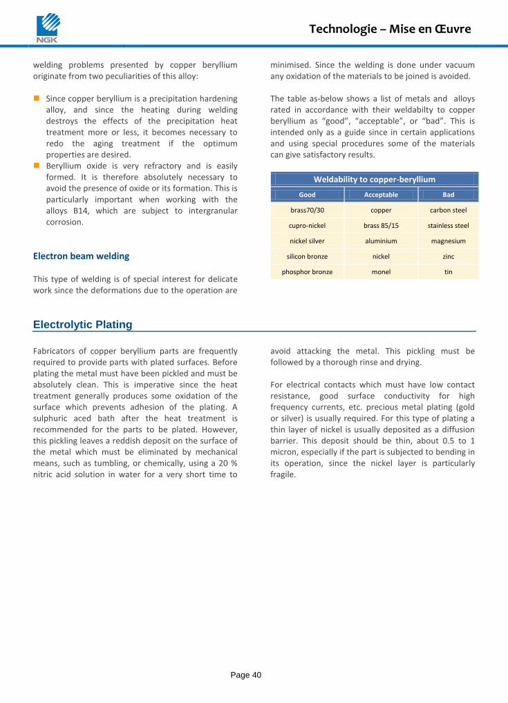
Technologie – Mise en Œuvre
Page 40
welding problems presented by copper beryllium originate from two peculiarities of this alloy: Since copper beryllium is a precipitation hardening
alloy, and since the heating during welding destroys the effects of the precipitation heat treatment more or less, it becomes necessary to redo the aging treatment if the optimum properties are desired.
Beryllium oxide is very refractory and is easily formed. It is therefore absolutely necessary to avoid the presence of oxide or its formation. This is particularly important when working with the alloys B14, which are subject to intergranular corrosion.
Electron beam welding This type of welding is of special interest for delicate work since the deformations due to the operation are
minimised. Since the welding is done under vacuum any oxidation of the materials to be joined is avoided. The table as-below shows a list of metals and alloys rated in accordance with their weldabilty to copper beryllium as “good”, “acceptable”, or “bad”. This is intended only as a guide since in certain applications and using special procedures some of the materials can give satisfactory results.
Weldability to copper-beryllium
Good Acceptable Bad
brass70/30 copper carbon steel
cupro-nickel brass 85/15 stainless steel
nickel silver aluminium magnesium
silicon bronze nickel zinc
phosphor bronze monel tin
Electrolytic Plating
Fabricators of copper beryllium parts are frequently required to provide parts with plated surfaces. Before plating the metal must have been pickled and must be absolutely clean. This is imperative since the heat treatment generally produces some oxidation of the surface which prevents adhesion of the plating. A sulphuric aced bath after the heat treatment is recommended for the parts to be plated. However, this pickling leaves a reddish deposit on the surface of the metal which must be eliminated by mechanical means, such as tumbling, or chemically, using a 20 % nitric acid solution in water for a very short time to
avoid attacking the metal. This pickling must be followed by a thorough rinse and drying. For electrical contacts which must have low contact resistance, good surface conductivity for high frequency currents, etc. precious metal plating (gold or silver) is usually required. For this type of plating a thin layer of nickel is usually deposited as a diffusion barrier. This deposit should be thin, about 0.5 to 1 micron, especially if the part is subjected to bending in its operation, since the nickel layer is particularly fragile.
Environment
Page 41
Industrial Hygiene
When supplied in solid form, beryllium copper alloys are non-hazardous, because Beryllium (<2%) has been completely dissolved into copper. General handling, stamping, forming, most machining operations, pickling, surface treatment, plating and heat treatment are non-hazardous and do not require any special precautions. As with other materials industry, beryllium alloys can pose a health risk if the recommended precautions are not followed. If they are subsequently processed in any way which might give rise to airborne dust or
fumes, for instance by dry grinding, abrading, electro-discharge machining, melting or welding, then an inhalation hazard could arise. Inhalation of beryllium oxide may cause respiratory irritation. Any such process requires suitable air extraction and filtration to maintain Be level of 2 µg/m
3 of air per working day, value set up by the
Ministry of Labour as the average Permissible Exposure Limit (PEL) has not to be exceeded. The use of cutting fluid can reduce emissions of dust in the atmosphere.
European Directives The NGK Insulators group is recognized as a world leader in the manufacture of beryllium-copper alloys. As such, we have always had a policy to provide our customers with safe and environmentally friendly products, which fully comply with current legislation in order to ensure the sustainability of our services. As a leading manufacturer in Europe, NGK Berylco actively participates in European environmental studies on substances used in our products.
RoHS Compliance RoHS Directive stands for ‘Restriction of the use of certain Hazardous Substances in electrical and electronic equipment’. The aims of the RoHS directive (2002/95/CE) is to regulate the use of certain dangerous substances. Since 1
st July 2006, all EEE,
imported or manufactured in the EU, placed on the EU market should comply with the requirements of this directive. RoHS recast in 2001 (2011/65/CE, RoHS 2) does not include any restriction on beryllium and consequently on the use of copper-beryllium as indicated by our ‘RoHS Ready’ logo.
REACH Compliance REACH stands for ‘Registration, Evaluation Authorisation and restriction of Chemicals’ which enter into force on 1
st June 2007. The main REACH
objective is to improve the protection of human health and the environment. Even if our copper-beryllium products are considered as being ‘articles’ under REACH, NGK Berylco registered beryllium metal
in November 2010 (No. 01-2119487146-32-0003). This procedure gave us the opportunity to make new scientific studies which concluded that beryllium should be reclassified. The industry is currently working with the European Institutions and Member States to update the current cancer classification as well as to demonstrate that beryllium metal, is like many other metals, safe when used correctly. Beryllium is not included in the REACH Candidate List (Annex XIV).
Recycling NGK Berylco is consistently monitoring any environmental regulations to ensure the compliance of our products to our customers. Our company is committed to continuous improvement to which all employees are commited. Our aim is to manage our environmental impacts, to act responsibly and actively participate in protecting the environment today and tomorrow. A precise and rigorous systematic recycling of all waste generation such as metal working oils, acids, water cooling, etc. is established. For more information concerning the non hazardous use or to request our product safety information sheets (SIS), please contact our environmental department.
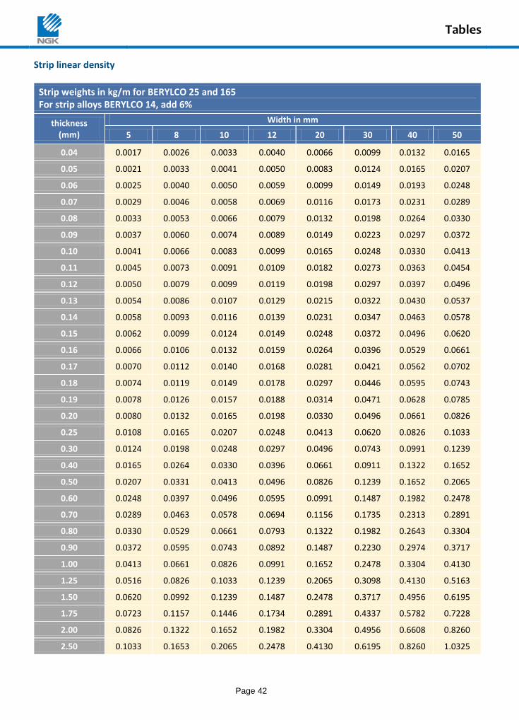
Tables
Page 42
Strip linear density
Strip weights in kg/m for BERYLCO 25 and 165 For strip alloys BERYLCO 14, add 6%
thickness (mm)
Width in mm
5 8 10 12 20 30 40 50
0.04 0.0017 0.0026 0.0033 0.0040 0.0066 0.0099 0.0132 0.0165
0.05 0.0021 0.0033 0.0041 0.0050 0.0083 0.0124 0.0165 0.0207
0.06 0.0025 0.0040 0.0050 0.0059 0.0099 0.0149 0.0193 0.0248
0.07 0.0029 0.0046 0.0058 0.0069 0.0116 0.0173 0.0231 0.0289
0.08 0.0033 0.0053 0.0066 0.0079 0.0132 0.0198 0.0264 0.0330
0.09 0.0037 0.0060 0.0074 0.0089 0.0149 0.0223 0.0297 0.0372
0.10 0.0041 0.0066 0.0083 0.0099 0.0165 0.0248 0.0330 0.0413
0.11 0.0045 0.0073 0.0091 0.0109 0.0182 0.0273 0.0363 0.0454
0.12 0.0050 0.0079 0.0099 0.0119 0.0198 0.0297 0.0397 0.0496
0.13 0.0054 0.0086 0.0107 0.0129 0.0215 0.0322 0.0430 0.0537
0.14 0.0058 0.0093 0.0116 0.0139 0.0231 0.0347 0.0463 0.0578
0.15 0.0062 0.0099 0.0124 0.0149 0.0248 0.0372 0.0496 0.0620
0.16 0.0066 0.0106 0.0132 0.0159 0.0264 0.0396 0.0529 0.0661
0.17 0.0070 0.0112 0.0140 0.0168 0.0281 0.0421 0.0562 0.0702
0.18 0.0074 0.0119 0.0149 0.0178 0.0297 0.0446 0.0595 0.0743
0.19 0.0078 0.0126 0.0157 0.0188 0.0314 0.0471 0.0628 0.0785
0.20 0.0080 0.0132 0.0165 0.0198 0.0330 0.0496 0.0661 0.0826
0.25 0.0108 0.0165 0.0207 0.0248 0.0413 0.0620 0.0826 0.1033
0.30 0.0124 0.0198 0.0248 0.0297 0.0496 0.0743 0.0991 0.1239
0.40 0.0165 0.0264 0.0330 0.0396 0.0661 0.0911 0.1322 0.1652
0.50 0.0207 0.0331 0.0413 0.0496 0.0826 0.1239 0.1652 0.2065
0.60 0.0248 0.0397 0.0496 0.0595 0.0991 0.1487 0.1982 0.2478
0.70 0.0289 0.0463 0.0578 0.0694 0.1156 0.1735 0.2313 0.2891
0.80 0.0330 0.0529 0.0661 0.0793 0.1322 0.1982 0.2643 0.3304
0.90 0.0372 0.0595 0.0743 0.0892 0.1487 0.2230 0.2974 0.3717
1.00 0.0413 0.0661 0.0826 0.0991 0.1652 0.2478 0.3304 0.4130
1.25 0.0516 0.0826 0.1033 0.1239 0.2065 0.3098 0.4130 0.5163
1.50 0.0620 0.0992 0.1239 0.1487 0.2478 0.3717 0.4956 0.6195
1.75 0.0723 0.1157 0.1446 0.1734 0.2891 0.4337 0.5782 0.7228
2.00 0.0826 0.1322 0.1652 0.1982 0.3304 0.4956 0.6608 0.8260
2.50 0.1033 0.1653 0.2065 0.2478 0.4130 0.6195 0.8260 1.0325
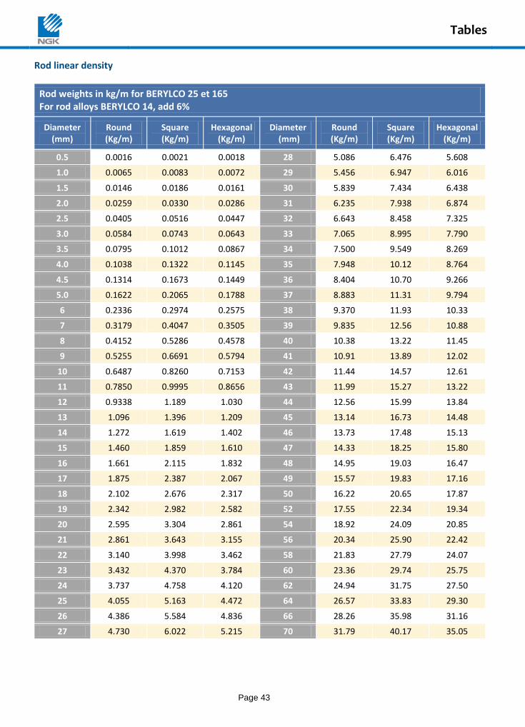
Tables
Page 43
Rod linear density
Rod weights in kg/m for BERYLCO 25 et 165 For rod alloys BERYLCO 14, add 6%
Diameter (mm)
Round (Kg/m)
Square (Kg/m)
Hexagonal (Kg/m)
Diameter (mm)
Round (Kg/m)
Square (Kg/m)
Hexagonal (Kg/m)
0.5 0.0016 0.0021 0.0018 28 5.086 6.476 5.608
1.0 0.0065 0.0083 0.0072 29 5.456 6.947 6.016
1.5 0.0146 0.0186 0.0161 30 5.839 7.434 6.438
2.0 0.0259 0.0330 0.0286 31 6.235 7.938 6.874
2.5 0.0405 0.0516 0.0447 32 6.643 8.458 7.325
3.0 0.0584 0.0743 0.0643 33 7.065 8.995 7.790
3.5 0.0795 0.1012 0.0867 34 7.500 9.549 8.269
4.0 0.1038 0.1322 0.1145 35 7.948 10.12 8.764
4.5 0.1314 0.1673 0.1449 36 8.404 10.70 9.266
5.0 0.1622 0.2065 0.1788 37 8.883 11.31 9.794
6 0.2336 0.2974 0.2575 38 9.370 11.93 10.33
7 0.3179 0.4047 0.3505 39 9.835 12.56 10.88
8 0.4152 0.5286 0.4578 40 10.38 13.22 11.45
9 0.5255 0.6691 0.5794 41 10.91 13.89 12.02
10 0.6487 0.8260 0.7153 42 11.44 14.57 12.61
11 0.7850 0.9995 0.8656 43 11.99 15.27 13.22
12 0.9338 1.189 1.030 44 12.56 15.99 13.84
13 1.096 1.396 1.209 45 13.14 16.73 14.48
14 1.272 1.619 1.402 46 13.73 17.48 15.13
15 1.460 1.859 1.610 47 14.33 18.25 15.80
16 1.661 2.115 1.832 48 14.95 19.03 16.47
17 1.875 2.387 2.067 49 15.57 19.83 17.16
18 2.102 2.676 2.317 50 16.22 20.65 17.87
19 2.342 2.982 2.582 52 17.55 22.34 19.34
20 2.595 3.304 2.861 54 18.92 24.09 20.85
21 2.861 3.643 3.155 56 20.34 25.90 22.42
22 3.140 3.998 3.462 58 21.83 27.79 24.07
23 3.432 4.370 3.784 60 23.36 29.74 25.75
24 3.737 4.758 4.120 62 24.94 31.75 27.50
25 4.055 5.163 4.472 64 26.57 33.83 29.30
26 4.386 5.584 4.836 66 28.26 35.98 31.16
27 4.730 6.022 5.215 70 31.79 40.17 35.05
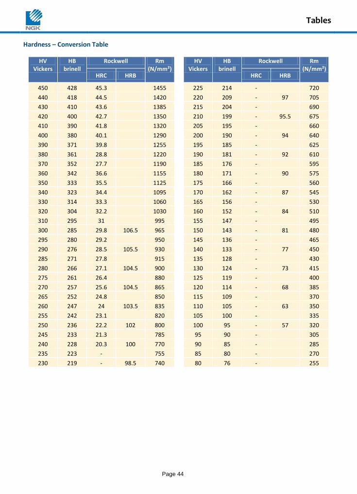
Tables
Page 44
Hardness – Conversion Table
HV Vickers
HB brinell
Rockwell Rm (N/mm²)
HV Vickers
HB brinell
Rockwell Rm (N/mm²)
HRC HRB HRC HRB
450 428 45.3 1455 225 214 - 720
440 418 44.5 1420 220 209 - 97 705
430 410 43.6 1385 215 204 - 690
420 400 42.7 1350 210 199 - 95.5 675
410 390 41.8 1320 205 195 - 660
400 380 40.1 1290 200 190 - 94 640
390 371 39.8 1255 195 185 - 625
380 361 28.8 1220 190 181 - 92 610
370 352 27.7 1190 185 176 - 595
360 342 36.6 1155 180 171 - 90 575
350 333 35.5 1125 175 166 - 560
340 323 34.4 1095 170 162 - 87 545
330 314 33.3 1060 165 156 - 530
320 304 32.2 1030 160 152 - 84 510
310 295 31 995 155 147 - 495
300 285 29.8 106.5 965 150 143 - 81 480
295 280 29.2 950 145 136 - 465
290 276 28.5 105.5 930 140 133 - 77 450
285 271 27.8 915 135 128 - 430
280 266 27.1 104.5 900 130 124 - 73 415
275 261 26.4 880 125 119 - 400
270 257 25.6 104.5 865 120 114 - 68 385
265 252 24.8 850 115 109 - 370
260 247 24 103.5 835 110 105 - 63 350
255 242 23.1 820 105 100 - 335
250 236 22.2 102 800 100 95 - 57 320
245 233 21.3 785 95 90 - 305
240 228 20.3 100 770 90 85 - 285
235 223 - 755 85 80 - 270
230 219 - 98.5 740 80 76 - 255

Notes
Page 45
MEMO :
More information at www.ngk-alloys.com
Edition 01/2014 Copyright © 2014 by NGK Berylco Europe
EUROPE
FRANCE GREAT BRITAIN GERMANY NGK BERYLCO France NGK BERYLCO UK Ltd NGK Deutsche BERYLCO GmbH 103 Quai Jean Pierre Fougerat, CS 20017, Houston Park, Montford Street, Westerbachstraße 32 44220 Couëron, France Salford, M50 2RP, U.K. 61476 Kronberg Im Taunus, Germany Tel : +33 (0)2 40 38 67 50 Tel: +44 (0)161-745-7162 Tel: +49 (0) 6173 993 400 Fax: +33 (0)2 40 38 09 95 Fax: +44 (0)161-745-7520 Fax: +49 (0) 6173 993 401
SPAIN SWITZERLAND ITALY Massague Rep. Ind. SA Notz Metall SA Tecnicom Calle la Ginesta, 6, Apt de Correos 47 Rte de Berne 24 Via G. Passeroni, 6 08 830 Sant Boi de Llobregat, España CH - 2555 Brügg 20135 MILANO, Italia Tel: +34 93 640 0573 Tel: +41 (0) 32 366 75 55 Tel: +39 (0)2 45506240 Fax: +34 93 630 2865 Fax: +41 (0) 32 366 77 34 Fax: +39 (0)2 39304926 www.massaguesa.com www.notzmetall.ch Email: [email protected]
ASIA
JAPAN CHINA CHINA NGK INSULATORS Ltd NGK INSULATORS Ltd NGK INSULATORS Investment Co Ltd New Metal Division, Shanghai Office, Shenzhen Branch Marunouchi Bldg.25F, 2-4-1, Marunouchi, Dawning Centre Tower A Room 1902, Room.8, Level.15, Tower 2, Chiyoda-ku, Tokyo, 100-6235, Japan No.500 Hongbaoshi Road, Kerry Plaza, No.1 Zhong Xin Si Road, Tel: +81 (0)3-6213-8913 Shanghai 201103, China Futian District Fax: +81 (0)3-6213-8973 Tel: +86-021-3209-8870 Shenzhen 518048, China www.ngk.co.jp Fax: +86-021-3209-8871 Tel : +86-755-3304 -3178 www.ngk.co.jp/cn www.ngk.co.jp/cn
AMERICA INDIA
USA INDIA NGK METALS Corporation NGK INSULATORS Ltd 917 U.S. Highway 11 South, New Delhi Liaison Office, Sweetwater, TN 37874, USA 601, 6th floor, DLF Place, A-4, Tel: +1 (800) 523-8268 District Centre, Saket Fax: +1 (877) 645-2328 New Delhi 110 017, India www.ngkmetals.com Tel: +91-11-4170-4020 www.ngk.co.jp
For more information, please visit our website
www.ngk-alloys.com
EN 9100 ISO 14001
Distributed by :