best available copy for all pictures - defense technical … · · 2014-04-08dd wom> 1*73 wi...
TRANSCRIPT

Best Available
Copy for all Pictures

AD-768 972
LASER-INDUCED DAMAGE IN OPTICAL MATERIALS
Concetto R . Giuliano
Hughes Research Laboratories
\
Prepared for:
Air Force Cambridge Research Laboratories Advanced Research Projects Agency
July 1973
DISTRIBUTED BY:
KTLJI National Technical Information Service U. S. DEPARTMENT OF COMMERCE 5285 Port Royal Road. Springfield Va. 22151

AFCRL- TR-73-0528
Ok
a x N
3
'41
LASER-INDUCED DAMAGE IN OPTICAL MATERIALS
By CONCETTO R. GiULIANO
HUGHES RESEARCH LABORATORIES 3011 MALIBU CANYON ROAD MAUBU, CALIFORNIA 90265
CONTRACT F19628-72-C-0348 PROJECT 2042
SEMIANNUAL TECHNICAL REPORT NO. 2
JULY 1973
CONTRACT MONITOR : HAROLD POSEN
SOLID STATE SCIENCES LABORATORY
APPROVED FOR PUBLIC RELEASE; DISTRIBUTION UNLIMITED.
Sponsored by DEFENSE ADVANCED RESEARCH PROJECTS AGENCY
ARPA ORDER 2042
Monitored by AIR FORCE CAMBRIDGE RESEARCH LABORATORIES
AIR FORCE SYSTEMS COMMAND UNITED STATES AIR FORCE
BEDFORD, MASSACHUSETTS 01730 C- D D
NOV 2 1913
B *'
mmm U^.tHHM mm MMMa

ARPA Order No.
Program Code No.
Contract No.
Contractor
Effective Date of Contract
Contract Expiration Date
Principal Investigator
AFCRL Project Scientist
204?
3D10
F19628-72-C-0348
Hughes Research Laboratories
15 June 1972
J5 December 1973
Dr. Concetto R. Giuliano (213) 456-6411, Ext. 437
Dr. Harold Posen (615) 861-3532
Qualified requestors may obtain additional copies from the Defense Documentation Center. All others should apply to the Nationa) Techni- cal Information Service.
id
mmm mam ..■J..- .. . ^.^^f* (^^gi J

UNCLASSIFIED Sccuriiy Classification
DOCUMENT CONTROL DATA • R&D (Security ctassiftcation of litte, body of abstratt and indexKxg annotation must be entered when the overall report is classified)
l. ORIGINATING ACTIVITY (Corporate author') Hughes Research Laboratories 3011 Malibu Canyon Road Malibu, California 90265
20. REPORT SECURITY CLASSIFICATION
UNCLASSIFIED *fc CROUP ""
1 REPORT TITLE
LASER-INDUCED DAMAGE IN OPTICAL MATERIALS
«. DESCRIPTIVE NOTES (Type of report and inclusive dates)
Scientific. Interim. S. AUTHOR(S) (First none, middle initial, last none)
Concetto R. Giuliano
t. REPORT DATE
July 1973 • a. CONTRACT OR SRAMT NO.
F19628-72-C-0348 b, PROJECT. TASK, WORK UNIT NOS.
2042 n/a n/a C. DOO ELEMENT
62701E d. DOD SUBELEMENT
n/a
7a TOTAL NO. OF PAGES 7i. NO. OF REFS
0 »a. ORIGINATOR'S REPORT NUMBElW '~
Semiannual Technical Report No. 2
AFCRL-TR-73-0528 •0. DISTRIBUTION STATEMENT
A - Approved for public release; distribution unlimited.
SUPPLEMENTARY NOTES
This research was supported by the Defense Advanced Research Projects
Agency
O. ABSTRACT
• 2. SPONSORING MILITAPY ACTl"ITY AF Cambridge Research Labs (LQ) L.G. Hanscom Fit 1H Bedford, Massachusetts 01730
This report contains the results of damage experiments performed at 0.694 and 1.06 ^m using well controlled ruby and NdrYAG lasers. Materials studied at 1.06 ^m are proustite (Ag3AsS3) and lithium niobate (LiNbOo). Proustite studies have been directed toward improving surface quality by employing different polishing techniques. Little or no improvement has been obtained over previously measured thresl olds. Chemical changes in proustite damage sites are evidenced by the use of electron excited x-ray microprobe measurements. Preliminary ion beam polishing experiments were performed on LiNbO-j, but no improvement in damage threshold was observed. However, the damage in this material appears to be inclusion limited in the samples studied so far. The temporal and spatial characteristics of laser pulses were studied for transmitted, reflected, and backscattered pulses both above and below surface damage tnreshold. These results show that the specularly reflected pulse cuts off at the same time as transmitted pulse. Light that is backscattered from 3 to 20 away from the beam shows a sharp increase in intensity at the time damage occurs. Preliminary indicetions of precatas- trophic damage are seen in these measurements in the form of temporal irregularities in the backscattered pulse below damage threshold.
Rvproducrd by
NATIONAL TECHNICAL INFORMATION SERVICE
U S 0*paftm#nt of Comm«rtt S|ir,ial.,IH VA 2;i31
DD wom> 1*73 w i NOV M '*"
ft UNCLASSIFIED Securiiv Classification
Mi MMMMM ■M — ■- ■

,.„■■ »wm^^^^iv, wm. i M^piBCSSW^^q^ w «MOTi • I ^i i n, -MW-.PT W^ "^ -^ LI ■-• ■WW« .-■ P ■» ■■ iw **3* "J» "^ ■
UNCLASSIFIED Security Classification
t«. KEY WORDS
ROLE WT
LINK B
HOLE WT
LINK C
ROLE
Surface damage
Proustite
Lithium niobate
Sapphire
0.694 ^m
1.06 ^im
Temporal and spatial irreguUrities
Reflected versus transmitted pulses
Backscattering studies
Precatastrophic damage
UNCLASSIFIED Security Classification
MMMMMMHII

v."" i >^v«^nW9|i^ '" I !■■ IIJU«
L J HUGHES AIRCRAFT COMPANY RESEARCH LABORATORIES
AFCRL-TR-73-0528
LASER-INDUCED DAMAGE IN OPTICAL MATERIALS
by
Concetto R. Giuliano
HUGHES RESEARCH LABORATORIES 3011 Malibu Canyon Road Malibu, California 90265
Contract No. F19628-72-C-0348 Project 2042
Semiannual Technical Report No. 2
July 1973 D D C
Contract Monitor: Harold Posen Solid State Sciences Laboratory
1 "^ r-l mq m ;! NOV 2 1913
IkiSEu sns B ^-'
Approved for public release: distribution unlimited
Sponsored by
Defense Advanced Research Projects Agency
ARPA Order 2042
Mom" tored by
AIR FORCE CAMBRIDGE RESEARCH LABORATORIES AIR FORCE SYSTEMS COMMAND
UNITED STATES AIR FORCE BEDFORD, MASSACHUSETTS 01730
M
*f i ■MM MMMMMBBM

■ ■ II^.WHWIIIJI^^»? IIIBIBI qji •^WTT- V^rv _ IJP«II.« IIPP.I .MJJJ IHIHILIl i JIHl J^lll
!
ABSTRACT
This report contains the results of damage experiments per-
formed at 0.694 and 1.06 pm using well controlled ruby and NdrYAG
lasers. Materials studied at 1.06 ^m are proustite (Ag,AsS.J and
lithium niobate (LiNbC^). Proustite studies have been directed
toward improving surface quality by employing different polishing
;hniques. Little or no improvement has been obtained over pre-
viously^neasured thresholds. Chemical changes in proustite damage
sites are evidenced by the use of electron excited x-ray microprobe
measurements. Preliminary ion beam polishing experiments were per-
formed on LiNbCK but no improvement in damage threshold was observed.
However, the damage in this material appears to be inclusion limited
in the samples studied so far. The temporal and spatial characteris-
tics of laser pulses were studied for transmitted, reflected, and back-
scattered pulses both above and below surface damage threshold.
These results show that the specularly reflected pulse cuts off at the
same time as transmitted pulse, Light that is backscattered from 3°
to 20 away from the beam shows a sharp increase in intensity at the
time damage occurs. Preliminary indications of precatastrophic
damage are seen in these measurements in the form of temporal
irregularities in the I ^Kscattered pulse below damage threshold.
iii
._ _ .

TABLE OF CONTENTS
ABSTRACT iii
LIST OF ILLUSTRATIONS vii
I INTRODUCTION AND SUMMARY 1
II DAMAGE EXPERIMENTS AT 1.06 MICRONS 3
A. Damage Experiments In Proustite (Ag3AsS3) 3
B. Proustite Damage on a Sample From a Different Source 5
C. Chemical Changes Accompanying Darrage in Proustite 7
D. Search for Impurities in Proustite ... 11
E. Surface Damage in Lithium Niobate, LiNbO^ (Ion Polishing Experiments) ... 12
III STUDY OF TRANSMITTED, REFLECTED, AND SCATTERED LASER LIGHT DURING THE GENERATION OF SURFACE DAMAGE 17
A. Integrated Transmission and Reflection of Laser Damage Pulses 17
B. Temporal Study of Transmitted and Reflected Damaging Pulses 19
C. Measurement«; of Backscattered La<er Light From he Surface During Damage 24
D. Precatastrophi: Damage Experiments ... 29
E. Spatial Properties ot Backscattered Light From Damaging Pulses 31
F. Summary of Pulse Temporal and Spatial Experiments 35
IV PLANS FOR NEXT PERIOD 37
Preceding page blank
i— mm mmtmm

" IWW i^lj MM J |RM^
LIST OF ILLUSTRATIONS
Fig. 1. Values of damage thresholds obtained in sequence on a freshly polished proustite surface 6
Fig. 2. Electron probe x-ray micrographs of a molten crater on proustite showing relative concentrations of Ag, As, and S 9
Fig. 3. Scanning electron micrographs of laser damage site on proustite 10
Fig. 4. Scanning electron micrographs of surface features on LiNb03 after ion beam polishing 14
Fig. 5. Experimental setup used in transmission and surface reflection measurements .... 18
Fig. 6. Integrated transmission and reflectivity of damaging laser pulses as a function of incident power on sapphire surfaces ... 20
Fig. 7. Temporal shapes of transmitted and reflected pulses for different powers relative to threshold for entrance damage 22
Fig. 8. Temporal shapes of transmitted and reflected pulses for different powers ... 23
Fig. 9, Experimental setup used in backscattering measurements 25
Fig. 10. Temporal profiles of laser pulses transmitted through and backscattered by sapphire samples 27
Fig. 11. Backscattered pulses compared with transmitted pulses below damage threshold 30
Fig. 12. Experimental setup for photographing spatial features of specularly reflected light 32
9 t vii
Preceding page blank
:
■W;

■""•^ i im» i II i •,fii<iii|4i|( nm i^mmmnmmqß
1 Fig. 13.
ng. 14.
Photographs of back-reflected beam for :ncreasing laser power above damage threshold .
Photographs of back-reflected beam for different aperture sizes between lens and sample ....
33
34
viii
jmma J

•mm** ■■■■if yiiiij^w^v.* i ■ jimr^v^^P!* ^n^mmrn1" « ■ ■> "ii -wi^m^r*
I. INTRODUCTION AND SUMMARY
In this report we present the results of our research on funda-
mental problems of laser induced damage in optical materials. The
activity during this period was centered at two optical wavelengths
0. 694 and 1 . 06 (im using ruby and NdrYAG lasers with well character-
ized and monitored spatial and temporal properties. The damage inves-
tigations of proustite have continued at 1,06 ^.m; «'ome new results have
been obtained with regard to obtaining a better surface finish but no
substantial increase in damage threshold has been achieved. The
phenomenon of ion beam polishing has been explored in a preliminary
way for LiNbO, on a number of different samples; *^e treatments have
not been successful so far, but the damage appears to be inclusion
limited and not an intrinsic property of the host material.
The fundamentals of surface damage have been explored further
using the Q-switched ruby laser. In those experiments the temooral
and spatial properties of backscattered and specularly reflected light
have been studied and compared with transmitted light temporal profile.
It is found that an appreciable amount of light is scattered out of the
beam in the back direction at the time of damage. Some preliminary
evidence for precatastrophic damage is presented in the form of
temporal irregularities in the backscattered pulse in the absence of
any other evidence for damage. The possibility that signs of damage
can be seen before catastrophic failure occurs is an exciting one and
opens up an important area for ; vestigation.
MM —

■"- •.'W.' I w^^^-" "^•vnfl'wwvr'wwii^'wi.fw'ji" •^•wwpi
ii. DAMAGE EXPERIMENTS AT 1.06 MICRONS
A. Damage Experiments in Proustite (Ag-iAsS-,)
During this period v,e have continued to study damage in proust-
ite at 1.06 ^m using the high power Nd:YAG laser described in the last
report. The pulse duration of this laser (FWHM) is in the range 16.5
to 18.5 nsec. For the damage experiments reported earlier the laser
output was focused on the proustite entrance surface using a 10.6 cm
focal length lens. More recently it has been convenient to employ a
shorter focal length lens (3.3 cm) for the proustite damage experi-
men.s. The experimental setup is essentially the same as that employed
earlier and described in Semiannual Tpshnical Report No. 1. The
gaussian spot size measurements at the location of the sample surface
were carried out in the same manner as described previously.
The main purpose of the proustite experiments during this
period was to explore the possibility of obtaining a better surface
finish and hence possibly a higher damage threshold. A number of dif-
ferent polishing -nethods were tried both with respect to polishing com-
pound and lapping surface; a variety of results were obtained, mostly
negative. For example, Syton, a Monsanto product which is an alkaline
suspension of SiO? in water, was tried as a polishing compound. This
material has been found to be an excellent prlishing compound for a
variety of different materials from metals to refractory oxides and
glasses but on proustite the result was a blackening and severe etching
of the surface presumably via a chemical reaction with the hydroxide
ions.
Procedures which did result in some improvement in surface
quality were the use of 0.05 |j.m fumed silica in water using a medium
pitch lap, as well as 0.05 ^m ■y-alumina in water on a pitch Lap. The
main different between these polishing methods and the one used earlier
is that a paraffin lap was used in the early polishing methods. Although
some qualitative improvement was achieved in surface finish (e.g.,
lower density of scratches) there was not an appreciable increase in
damage threshold.
Preceding page blank i
mmmmmm

Table I shows resuiLc obtained for different polishing conditions
on the same sample.
Several features should be brought up in discussing the results
presented in Table I. First, the reason for the difference between the
results obtained for the two spot sizes is not completely clear. The
data were taken at different times and the surface condition of the
sample was not necessarily the same although it was prepared in the
same manner. It is possible that the average value of damage threshold
might be higher for a smaller spot size because the chance of encounter-
ing a low threshold region (assuming a certain distribution of absorb-
ing inclusions) on each shot is less in general for a small spot than for
a larger one. But one would expect that e^en though the average value
might be higher, the range of values should overlap somewhat, especially
on the low side (i.e., one should occasionally encounter low threshold
regions with the small spot size as well). Of cours';, the number of
thresholds measured is not large enough in these cases to preclude
the possibilitv that this spot size effect is a reflection of the distribu-
tion of inclusions and/or s.rface defects.
TAB LE I
Damage Thresholds for Proustite Sample With Different Polishing Conditions (17.5 nsec pulse)
Conditions
Dunag* Th'eslvpi-I.
J cm (average valv. *)
Range Number of Th resholds Measured
Beam radius, pm
y-Al^Oj on 0.71^ 0.M to 1.0 17 K6 paraffin
■y-AI^Oj on l.ll 1.17 to 1.4'i 1 1 4S paraffin
fumed silica l.*< I.M to z.oi 14 4S on pitch
F urned silica 1.71 1.04 to 3. 11 13 4S on pitch (fresh polish)
aThpse values are (jiven a-, the total energy divided by the beam area defined as wo where o is the 1/e radius for the electru field. The energy densi- ties on-axis are twice as large as the values quoted in the table.
Defined at the 1 fm point» for the electric field (the 1 /e points for the intensity) for a gaussian beam.
T97f,
m- ii i

Of more significance, however, is the last entry labeled "fresh
polish." In mcst instances, as discovered earlie r, the threshold mea-
surements on (,roustite are carried out on samples that have been
recently polished, usually on the same day. This practice was under-
taken because it was found that the surface was seen to accumulate a
cloudy appearance within a few hours of polishing when viewed with
appropiiate illumination under magnification. Typically the damage
thresholds would begin to drift downward as the cloudiness would
develop; after one or two days of standing in air the threshold would
level off to a value sometimes as much as a factor of two lower than
those obtained in the first few hours of measurement.
This type of behavior was most striking in the series of experi-
ments that resulted in the last entry in Table I (fresh polish). This
phenomenon is illustrated in Fig. 1 which s-ow* th threshold results
as obtained sequentially for a scries of sr-Aa on the sample surface
each separated by 0.5 mm. The gradual dropoff referred to above can
be seen in the figure. The threshold value reported in Table I is an average of all
the thresholds measured. However, it ran be seen (Fig. 1) that the
first few points measured result in lifting the average considerably.
The total sequence of measurements illustrated in Fig. I represent
about 100 shuts of the laser and required most of a full dav to carry
out. This kind of behavior illustrates the difficulty one laces in obtain-
ing meaningful damage threshold data for proustite.
B. Proustite Damage on a Sample Fr-^m a Different Source
In addition to the series of experiments just descrii ed we had
the opportunity to measure damage threshold on a proustil- sample
obtained from a different source than previous samples. Earlier
proustite crystals were either grown at HRF or obtained from the
Royal Radar Establishment (RRE). Samples from these sources i ad
about the same damage threshold (within an average of ~50%) for
similar conditions of pulse duration and focusing. Recently we obtained
a slice from a proustite boule grovn by the British Drug House (BDH),
formerly a supplier of raw material for proustite crystal growth.
■MMMHMi

iiiji mi.ipi j. i i i iu.ui.iin mwm.m*' '*w"-i'ji.m
> « 5 6 7 8 9 10 M SEQUENCE OF DAMAGE SITES MEASURED
2S9I-I
Fig. 1. Values of damage thresholds obtained in sequence on a freshly polished proustite surface.
——ti^ »if

1 ■ M ■« ■ **t*w**rwi*r*m?' i—!•«■■■ in _ np^pm^iHvii in, mw^r'^frtf^mr^w^iirr
The sample was polished by the technique described (fumed
silica, pitch lap) and a series of surface damage threshold measure-
ments was carried out.
As a (omparison to the entries lor the «ample in Table I (an
RRE sample), the BDH sample was damaged under the same focusing
conditions as the latter entries (45 ^m spot radius). The damage
threshold energy density was 1.37 j/cm , an average of 27 different
sites with values ranging from 1.1 to 2,0 j/cm .
One feature that distinguished the BDH sample from previously
studied proustite samples, is the morphology for surface damage formed
rear threshold. As illustrated in Semiannual Technical Report No. 1,
the pulsed damage near threshold is characterized by a number of tiny
molten areas clustered around surface scratches. Besides, the
damage formed near threshold is rarely accompanied by the occurrence
of a spark; surface sparks are usually seen on proustite ir the incident
energy is appreciably above threshold. For the BDH sample, however,
the damage in all but 2 of the 27 cases observed consisted of a single
surface pit and was accompanied by a spark.
The reason for this is not completely clear but we believe it
is an indication of a more unilorm surface quality on this sample.
The damage thresholds measured are not appreciably different from
those measured under similar conditions for the RRE sample, but the
fact that the morphology consisted of a single damage crater rather than
a cluster of molten globules indicates that if the damage is limited by
inclusions or other absorbing sites in the BDH sample they are more
uniformly distributed than they are in the RRE samples studied.
C. Chemical Changes Accompanying Damage in Pn ustite
During this period we have explored the damage sites in
proustite with respect to the possioility of chemical changes. As
mentioned in the last report, the catastrophic surface damage caused
by cw illumination is accompanied by a tiny plume of yellow smoke
(presumably sulfur) emanating from the damage site.
mmm

"'" ^p IHM! ! Jl.u ll • » ■ '•■■ ii»" - • » "Uli "w«iiiii Ljuiif .jvawneifwwwi 1,1 HI ■ ■ ^^H«H
This suggestion of chemical decomposition during laser damage
led us to confirm it by other means and to determine whether similar
decomposition might accompany other types of proustite surface damage
(e.g., pulsed) as .veil.
To explore the surface composition we used an electron excited
x-ray microprobe apparatus. This phenomenon employs a focused elec-
tron beam on the surface that locally excites atoms found in the beam.
These excited atoms emit characceristic x rays that are measured in an
x-ray spectrometer. The apparatus used has a scanning electron beam
caoahility as well, and the different regions being probed can be dis-
pla/ed as on an electron microscope.
Results of a microprobe analysis are shown in Fig. 2. Here
we see an electron micrograph of a damage site caused by cw illumina-
tion. Accompanying the micrograph is a series of dot patterns taken
over the same region of the surface as seen in the micrograph. The
brightness of the dot pattern in a given region is a measure of the
amount of the element in question found in that region.
From these pictures we see (not surprisingly) that there is a
definite chemical change accompanying this type of proustite damage.
There is, for example, a buildup ot arsenic at the crater rim and a
deficiency at the center. On the other hand, the center of the crater
is rich in silver relative to the rim. The sulfur distribution is asym-
metric as suggested by the yel'ow plume as indicated above.
Other types of proustite surface damage as illustrated in the
last report were explored using the technique described above and no
evidence for stoichiometric changes were seen in these experiments.
Thus we conclude on the basis of this brief investigation that proustite
damage is accompanied by chemical decomposition only for catastrophic
effects caused by continuous illumination.
An added fact in connection with obtaining the above data is that
proustite is damaged by the scanning electron beam used to excite the
x-ray microprobe unless the beam current is kept at a relatively low
value. An example of this type of e-beam damage is shown in Fig. 3.
... .^ .--.■

1
Fig. 2. Electron probe x-ray micrographs of a molten crater on proustite showing relative concentra tions of Ag, As, and S.
I J

mm^mmmmmm^m
2S5I-I4
LASER DAMAGE CRATER
25SI-i5
DAMAGE CRATER AFTER ELECTRON SCAN
10/im
Fig. 3. Scanning electron micrographs of laser damage site on proustite before and after electron micro- probe scan showing damage to proustite surface due to high current electron beam.
,(i

rrrwr- 1^r*im*^Kv* ■■^•«■w«".1«"l*1 mmmm!*^~^~*mi**mmim "■ « ■ ii 11 i ■■pii.iii«
After this damage was observed all subsequent scans were preceded and
followed by the taking of scanning electron micrographs (a very low
current requirement). In this way the region of interest could be
examined after the microprobe analysis was carried out ta ensure that
a nondamaging beam current was employed.
D. Search fur Imt-uritu.-.-j in Proustite
We have also used the x-ray microprobe technique for exploring
for the presence of surface contaminants. As reported earlier, the
near threshold damage morphology for proustite surfaces shows small
molten globules clustered around surface scratches. It is possible that
these scratches or grooves co'..ld collect impurities that would be diffi-
cult to remove by conventional cleaning procedures or that they might
contain particles of polishing compound.
Even though the polishing abrasives used (SiO^i Al^O^) do not
absorb 1.06 pm light, there is the possibility that the presence of
abrasive particles on the surface could give rise to some increase in
local absorption in the vicinity of surface scratches.
The electron beam x-ray nücroprobe apparatus was used to
explore for the presence oi impurities on the surface. F^r a given
sample, many areas of the surface were scanned. Typically the elec-
tron beam would illuminate a region ol the surface 250 pm square and
the x-ray spectrometer would scan over all the elements, the detector
output being fed into a chart recorder. We have found from these mea-
surements that except for a weak chlorine peak, there is no indication
(within about 1 part in 10 ) of the presence of either aluminum or silicon,
Thus we con.-.lüde that there is no appreciable concentration of
foreign impurities in the region of surface irregularities and that little
or no abrasive par.icles are present in surface scratches or grooves.
I 1
MMH
iwi«,«w IP» ■■ ■ n }.'1.i,mvm> i in» ■■ *'v^^^vwrmmwr**?
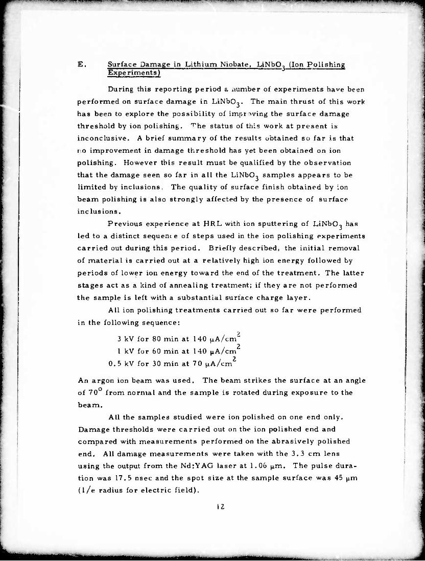
E. Surface Damage in Lithium Niobate, LiNbO, (Ion Polishing Experiments)
During this reporting period a uumber of experiments have been
performed on surface damage in LiNbOo. The main thrust of this work
has been to explore the possibility of improving the surface damage
threshold by ion polishing, ^he status of this work at present is
inconclusive. A brief summary of the result? obtained so far is that
i o improvement in damage threshold has yet been obtained on ion
polishing. However this result must be qualified by the observation
that the damage seen so far in all the LiNbO^ samples appears to be
limited by inclusions. The quality of surface finish obtained by ion
beam polishing is also strongly affected by the presence of surface
inclusions.
Previous experience at HRL with ion sputtering of LiNbCK has
led to a distinct sequenc e of steps used in the ion polishing experiments
carried out during this period. Briefly described, the initial removal
of material is carried out at a relatively high ion energy followed by
periods of lower ion energy toward the end of the treatment. The latter
stages act as a kind of annealing treatment; if they are not performed
the sample is left with a substantial surface charge layer.
All ion polishing treatments carried out so far were performed
in the following sequence:
3 kV for 80 min at 140 ^A/cm i 2 1 kV for 60 min at 140 jiA/cm
0.5 kV for 30 min at 70 ^A/cm
An argon ion beam was used. The beam strikes the surface at an angle
of 70 from normal and the sample is rotated during exposure to the
beam.
All the samples studied were ion polished on one end only.
Damage thresholds were carried out on the ion polished end and
compared with measurements performed on the abrasively polished
end. All damage measurements were taken with the 3.3 cm lens
using the output from the NdrYAG laser at 1.06 ^m. The pulse dura-
tion was 17.5 nsec and the spot size at the sample surface was 45 ^.m
(l/e radius for electric field).
12
MHBB

mt^i** ■w >* •" ••* > " imp ii in i« ii ■■■ ^4« ■■!■•
Damage threshold po'ver densities are presented in Table II.
We see from the data in Table II that the ion polished surfaces
have typically lower damage thresholds than the aorasive polished sur-
faces. However, it should be pointed out that the damage appears to
be limited in all cases by the presence of inclusions. We base this
statement on the following:
1. In a number of cases where we attempted to generate entrance surface d. mage by focus- ing the laser appropriately we generated bulk damage instead. The bulk damage was characterized by either a series of small fractured sites along the beam or by one or two internal cracks randomly located in the material.
2. The ion polished surfaces were characterized by a number of irregularities not present on the abrasively polished surface which first appeared to be depressions or small craters but subsequently were seen to be small raised mcands. The presence of these irregu- larities suggests the existence of surface inclusions that have a different rate of removal in the ion. beam than the host material. This type of surface feature is illustrated in the scanning electron micrographs of Fig. 4. For this surface the ion exposure was prolonged in order to emphasize the surface features.
Thus we conclude that the samples of LiNbO, studied so far
have a sufficiently high density of inclusions that essentially all the
damage levels measured so far are not a measure of intrinsic
material. Hence the possibility of improving the material quality
via ion polishing is still an open one.
13
u^mmm—m

"^c^^^^F^fvrm* ^mm~7—^mm^*^ -^^^w^vw^^mi^m --^^••^m^^^v^ "^^^■■■»■i« 1" i "»■•■»■•■■^ppw
ZSSI-IO
(a)
2551-11
(b)
Fig. 4. Scanning electron micrographs of sur- face features on LINbO. after ion beam polishing.
14
■■

■ .iwii|w^wmni|^3(»»BwmM«».o'- II I iw^> «Pi ■ ■ ■■»^ IIH'I ^»»»Wl^WWWW^WtW»* «WWl^MHni
TABLE II
Surface Damage Thresholds for LiNbOo Samples at 1.06 |j.m Ion Polish versus Abrasive Polish
Sample
Threshold Power Density,a GW/'cm2
Number of Thresholds Meaeured
Abrasive Polish
Ion Polish
Abrasive Polished
End
Ion Polished
End
A
B
C
D
E
1.01
2.29
I. 10
2.82
1.43
1.20
1.24
2.40
0.76
14
7
11
10
9
10
6
10
5
The values are given as the totil power divided by the beam area defined is TO, • where o. is the l/e radius for the electric field. The on-axis power densities are twice the values listed in the table.
T997
IS
«■■««■■MMUHaafti

^rwur^pGm
M
III. STUDY OF TRANSMITTED, REFLECTED, AlID SCATTERED LASER LIGHT DURING THE GENERATION OF SURFACE DAMAGE
During this reporting period we have pursued a series of mea-
surements reported In Semiannual Technical Report No. 1. The pur-
pose of this work is to characterise in detail the las?r pulse with
respect to instantaneous intensity, total energy, and spatial properties
during the generation cf surface damage.
To this end we have examined the temporal shape of both trans-
mitted and reflected pulses as a function of incident power below and
above damage threshold for both entrance and exit surfaces. The
total integrated pulse energv has been monitored as a function of
power for both reflected and transmitted light. Besides having
examined the light that is reflected specularly from the sample surface
we also measured the temporal and jpatial properties of light that is
scattered out of the main reflected beam at moderate angles. For the
studies we have used the single mode ruby laser focused on sapphire
samples, but it is evident from other cursory observations that the
.esults apply more generally to other materials and optical wavelengths.
A. Integrated Transmission and Reflection of T-aser Damage Pulses
In the last report we presented data on integrate percent trans-
mission as a function of power for laser pulses. Further work has been
carried out during this period in which we measured the reflected energy
as well. The main motivation for this work has been to determine whether
the decrease in transmission of damaging pulses is accompanied by a
corresponding increase in reflec tion as might be expected if the surface
plasma density reaches a sufficiently high value.
The experimental setup for monitoring the varlc. is pulses is
shown in Fig. 5. For the transmission experiments, the output from
the detector located after the sample (detector No. 2) is integrated
electrically and displayed on one trace of a dual beam oscilloscope
(Tektronix 555) whil~ the signal from the detector that monitors the
incidfc it energy (detecto. No, 1) is displayed on the other trace.
Preceding page blank 17

. ■.pmnji. •lüP^ül«^""^!«»»-^»"*^»!"!^« > lHlliHHFW. IMiii i . ,vin«<i mmnij*iM\**irmimmm*m*^mimi «Jiiii.lli,
2551-7
DETECTOR NO 3
VARIABLE ATTENUATOR
INPUT LASER BEAM
DETECTOR NO 2
(GLAN-KAPPA POLARIZERS)
DETECTOR NO I
Fig. 5. Experimental setuo used in transmission and surface reflection measurements.
18
mam MMMMMM

"Wa*np*^«nqcPB.p (g i i j » i, i '"""—" ■■' " wm"Vi mi iwm'mm ■ mal n i v pwww-^vva^ap^p-nww^n ^■1
■
Appropx-iate ratios are mpasjred (jvrr a range ul incidetit power from
below damage threshold to many times above threshold. In a similar
manner the percent reflected energy was measured in another set of
experiments in which the reflected light that passes back through the
focusing lens is monitored by detector No. 3 and displayed on the
oscilloscope in place of the transmitted signal. The results of these
measurements are shown in Fig. 6.
Th« percent transmission data that appeared in the last report
are presented again for comparison with the reflectivity data. We see
from these curves that both transmission and reflection show a mono-
tonic decrease as the power increases above damage 'hi :.->nold.
B. Temporal Study of Transmitted and Refected Damaging Pulsr s
A series of experiments was carried out to simultaneously
study the ^mporal shape of transmitted and reflected pulses as a
function of incident power. The purpose of these ev jriments was
twofold: First, to determine whether the sharp drop in transmission
at the time of damage formation is ace ompanied by a corresponding
change in reflectivity at the same time, and second, to explore the
possibility that some temporal irregularities might be detectable in
the back reflected pulse in the absence of catastrophic damage. In
essence we were also exploring lor clues for precatastrophic damage
information.
As we will see later, examination of the back reflected light
showed no indication of precatastrophic behavior but there was some
evidence for such behavior when small angle backscattering away from
the directly back-reflected beam was studied.
For these experiments the outputs from detectors Z and 3 in
Fig. 5 were individually displayed on separate Tektronix 519 oscillo-
scopes. The use of either line filters or Wratten No. 70 red filters
assured that only laser light was detected. Both oscilloscopes were
externally triggered by a pulse taken from an additional biplanar photo-
diode that is normally used to monitor the oscillator output. This
external triggering scheme ersured that the two oscilloscopes are
19
MMMM — -

■tM*!.!«^ i>.,'^ "- ■•>■ ' iiw-'^^" ■/" ^l '■ ^-w^W ^"J.u-..«r^- p ijp « T^-f^wrwp ri.^-..»^ » -ii ...n, i » ■ ■ < '-^ j>
10 r-
8
>-" t 6 >
UJ
CE
0
100
80
o-0
KSSSSS-
2 60 CO
i z < Q:
40 -
20
1 I I l l | |
REFLECTION BELOW DAMAGE THRESHOLD
T I—T 2551-16
I I I I
~l 1 I I I I |
-TRANSMISSION BELOW DAMAGE THESH0LD
10
POWER DENSITY, GW/cm2
J—I l i I i J 2112-1
"I 1 I I II
100
Fig. 6. Integrated transmission and reflectivity of damag Tirg laser pulses as a function of i.^ident power on sapphire surfaces.
20
triggered at the same time (within less than 1 nsec). In this way
variations in pulse shape for transmitted and incident light can be
temporally related even though they are separately recorded.
For each of the oscillographs recorded a double exposure was
taken. In the first trace we recorded the signals when the laser was
fired at the sample with the focusing lens removed from the optical
path. For the second trace, the lens was appropriately positioned so
that the light was focused on the surface of interest and the laser was
fired again. The reprodi'jibility of the ruby laser-amplifier combina-
tion is suchthat in each case (i.e., with lens and without lens) the
total energy incident on the sample was the same (within ~5%). Hence,
in the absence of damage, each transmitted and reflected oscilloscope
photograph shows a pair of traces of the same shape and amplitude.
When damage occurred the temporal variations of the damaging pulse
can be compared relative to the nondamaging pulse both with respect
to transmitted light and reflected light. Experiments of this type were carried out in detail for both
entrance and exit surface damage on sapphire and the results of
representative shots for different incident laser power are shown in
Figs. 7 and 8. Because of the difficulty in reproducing high speed
oscilloscope photographs, tracings of these photographs are shown.
After a great deal of difficulty it was possible to obtain reliable trig-
gering and to eliminate all influence of stray scattered light on the
recorded signals.
The following features should be pointed out concerning the
traces in the figures under discussion:
• The back-reflected pulse cuts off at the same time as the transmitted pulse.
• Most temporal irregularities in the trans- mitted pulse are duplicated in the reflected pulse.
• The back-reflected intensity for a damaging pulse is always less than or equal to that of the reference pulse. That is, the specular reflectivity of the interface during the occur- rence of damage is always less than that of the undamaged interface.
21
M MMMMMM MMHMMl

IPVIPII »«UP^^WVPI ' 1HJL-.H ■ —^|P ■- ||l«< -ini.i^i i|i »-»-.- ti ipim fiivpawi nu pii iu II«.I . mil i ■ iipi^i^M
RELATIVE ENTRANCE DAMAGE 25SI-6
THRESHOLD POWER
TRANSMITTED PULSES
BELOW / \ THRESHOLD
_^ / s
~I.O x
~ 1.5 x
— 1.5 x
REFLECTED PULSES
/\ y^ JX- J\^
hAr- ÄB
~6 .0 x fflffla« ~8.0x
~l5.0x /
\
V
y L \
—►■ A—i 3 nsec
Fig. 7. Temporal shapes of transmitted and reflected pulses for different powers relative to threshold for entrance damage.
22
rta MMk —^tfMHMB

1*1 JIOTHIM Ml PL »i,«-—'■■'IB—• ■'■ P""«^ ■"■■ ' T^f^^r^l»!« .I.">»JI iiiBiiiiiiin will.1 ^»>"WI^W»pi
RELATIVE THRESHOLD
POWER
~ 1.0
EXIT DAMAGE 2551-5
TRANSMITTED PULSES REFLECTED PULSES
~l.5
^2 5
3 0
-4.0
-8.0 / \ / \ ^c \ A \ s^ LA tf\ --**
Fig. 8 Temporal shapes of transmit.ed and reflected pulses for different powers relative to threshold for exit damage.
23
Ü MHtebHtfB

ii"H4iif.Ii IWMIIJIII JVM^niV^mi^ ■«■.II« p IN i il l '»»*■' "lull«'- «ill« « ""..V1 " !""■ 'Il I II linn» IIIHIIIBWWH^P^'WWP»
Because of the lens diameter (1 in.) and distance from the
sample surface (20.7 cm) the total amount of reflected light collected
in the above described experiments wouk" have spanned a maximum
half angle of 3 5 .
C. Measurements of Backscattered Laser Light From the Surface During Damage
Since both the transmitted and reflected pulses show a sharp
decrease in intensity following the creation of damage one might be
inclined to attribute the loss of light to absorption by the damaged
region and/or surface plasma. However, there is al^o the possibil-
ity that an appreciable amount of the laser li^ht is scattered out of
the forward and back direction as well as absorbed.
A measurement of the amount of scattered light would require
the means for collecting and measuring the light scattered over all
directions or a knowledge of the scattering distribution and subsequent
sampling of the light over a particular solid angle. Measurements
of this type were not carried out in our experiments but a few experi-
ments were conducted that were aimed at determining the temporal
behavior of scattered light. Again, the purposes were: (1) To explore
the possibility that an appreciable amount of light might be scattered
out of the main beam, (2) to obtain a temporal correlation between
the scattered light and transmitted or specularly reflected light, and
(3) to explore the possibility that some indication of precatastrophic
damage might be found in the temporal characteristics of the scat'ered
light.
The experimental setup used for these experiments is shown
in Fig. 9. It is similar to the previous setup except that a white card
(3 in. square) with an aperture was placed approximately halfway
between the focusing lens and the sample. Detector No. 3 was placed
to monitor the diffuse laser light scattered back from the sample sur-
face onto the white card. The aperture diameter (6.5 mm) was sub-
stantially larger than the convergent beam diameter (1.7 mm) at the
point where it passed through the hole in the card.
24

"■■ '-' »^"»^^ ^^ i -r •■ i» ii|i ■ WI . mill '•"• •»'•J.^OT ■ « i i i • mt im\wmi I I ■
VARIABLE ATTENUATOR
INPUT LASER BEAM
(GLAN-KAPPA POLARIZERS)
DETECTOR ND 3 s /
r~>f* DETECTOR NO 2
SAMPLE
WHITE CARD WITH APERTURE
DETECTOR NO. I
Fig. 9. Experimental setup used in backscattering measurements
25

- --■"^'".P «**iw •' ■j---- . HF^l-.i .■>
The experimental data were obtained in a similar way that
the previously described data were taken; the laser was fired once
with the lens removed and the second time with the lens placed
appropriately in the beam, both pulses being recorded on the same
oscilloscope film.
The results of a number of these experiments are illustrated
in Fig. 10. Here the data are displayed differently than before in that
the scattered pulse has been inverted relative to the transmitted pulse
so that the temporal relationship can be more easily seen.
The general qualitative features seen in these traces are:
• The scattered light for damaging pulses is characterized by a sharply rising spike followed by a more slowly decaying tail.
• The peak of the scattered spike occurs at the same time that the transmitted pulse begins its sharp cutoff.
• The srattered intensity begins to rise from its background level before ^.he transmitted pulse shows any appreciable irregularity.
• In cases where very slight damage occurs so that the transmitted pulse shows little or no temporal irregularity, there is still an appreciable temporal irregularity in the scattered light.
The sensitivity of the backscattered amplitude shown in the
above experiments indicates that this type of monitoring is a more
sensitive indication of surface damage than examination of either the
transmitted or the specularly reflected light. Moreover, the fact that
the backscattered light begins to rise in intensity relative to the back-
ground before the transmitted light shows signs of cutoff suggests that
some evidence for precatastrophic damage may be indicated from this
kind of measurement.
26

'-MI nipupiiuiwi mr-*'"> '- • -^" - «w 11« i— ^ ^■"- ■ '^- ■ " i■ HI IIII 11 ■■ «v^vi^Qiopiiji i i^m^^Tm
Zbb. i
TRANS^fllT^ED
I I
BACKSCArTfTRED
10 nsec NEAR THRESHOLD
Fig. 10(a) Temporal profiles of laser pulses transmitted through and backscattered by sapphire samples at different powers relative to entrance sur- face damage threshold.
*
27
■■■ MnMMHMM

■" l-ff^- ^i"*ll -)— ■— ' "■p ^ V ^iWii ■ • ""■—_^-"" ..,.,., „ ,,„„ ,,.,... ,^.., j.u.. ...p^H,
29SI-4
TRANSMITTED
BACKSCATTERED
SLIGHTLY ABOVE THRESHOLD
Fig. 10(b). Continued
28
HtMMMflMdMa

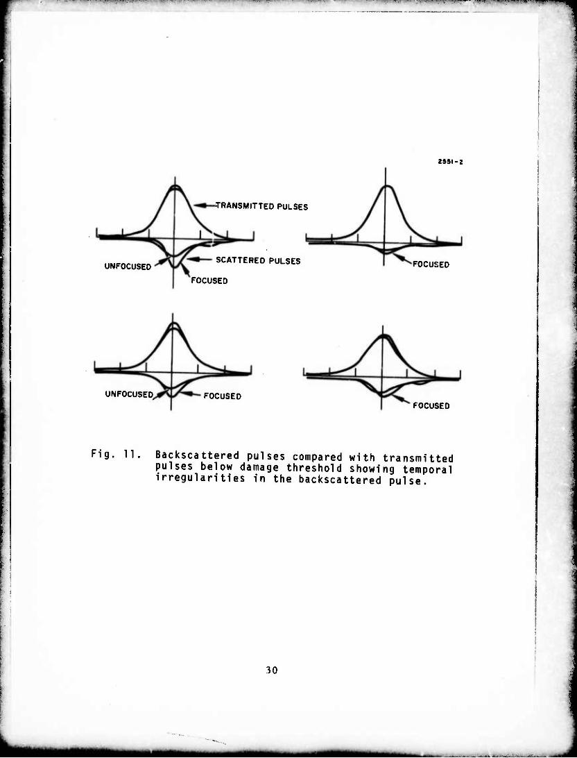
Dt Precataotrophic Damage Expt riments
Tentative evidence for precatastrophic damage indications
were seen in a few instances in the absence uf damage where the
scattered light shovvcd a definite irregularity compared with the bact
ground pulse. In these cases the transmitted ;nilses were essentially
identical with or without the focusing lens in place whereas the back-
scattered pulse with the lens in place had a different shape than the
pulse observed with the lens removed.
Examples of tliis behavior are shown in Fig. 11. We see that
the scattered pulse with the lens in place is different in shape from the
one where the lens is removed. In these examples the laser power
incident on the surface was very close to the value where damage
occurred but not sufficiently large to produce any detectable damage on
that particular shot. All the pulses in the examples shown were fol-
lowed by damage producing pulses of slightly higher energy.
Because of the detector sensitivity it is difficult to obtain large
signals at these levels of illumination. More detailed experiments of
this type with higher signal levels will indicate whether the effect
observed is really an indication of precatastrophic damage.
Since the background pulse in these experiments is one in which
the lens is removed from the system, the diameter of the beam is pass-
ing through the 6.5 nm aperture is different in the two cases. {The
diameter of the focused beam at the l/e intensity points is 1.7 mm
and that for the unfocused beam is ~4 mm.) Also, the size oi the
spot striking the sample surface is substantially differert. Since the
general background of scatter on the card will depend or. the surface
smoothness and general distribution of irregularities, scratcnes, etc.,
the level of the scattered signal is not expected to be the same for the
two pulses.
The temporal shapes however, should be the same for the scat-
tered pulses as for the transmitted pulses in the absence of damage
unless some subtle phenomenon is taking place.
Z<)
' mam MM
,WJJI^|li H.!. .' »■^Ä"' ■4'TT"' •!">**•• ■'i.B I" .—»--—WI--^^
2951-2
-TRANSMITTED PULSES
UNFOCUSED SCATTERED PULSES
FOCUSED
FOCUSED
UNFOCUSED FOCUSED FOCUSED
Fig. 11, Backscattered pulses compared with transmitted pulses below damage threshold showing temporal irregularities in the backscattered pulse.
30
Mk^

mm MVPWNPP^W mnm^t^m^^^m^mrmrwi^mm-^^^w^r^mtm ■ IPI MMI '! iPiii«w^i»^w»p»i^^wB»*pw^r'*F^WP"
i possible explanation is a precatastrophic surface phenomenon
such as a slight local heating resulting in an effective local curvature
at the surface that could deflect the beam temporarily off axis. Another
is the production of a microscopic plasma that is not visually detect-
able but that results in a subtle off axis backscattered component.
At this time we cannot preclude the possibility that the
phenomena illustrated in Fig. 11 might arise from a spatial peculiarity
of the focused beam relative to the unfocused beam that could result
in a difference in temporal behavior of the scattered light. Because
some of the light detected occurs in the wings of the spatial distribution,
there may be a subtle temporal difference between the two beams,
especially if the laser is not oscillating in a single longitudinal mode.
This possibility is not a likely one, but only more detailed experiments
will allow us to eliminate it.
E. Spatial Properties of Backscattered Light From Damaging Pulses
The fact that a measurable amount of light is scattered out of
the specularly reflected beam for damaging pulses led to the question
concerning its spatial distribution. To this end an experiment was
carried out, as illustrated in Fig. 12, where the specularly reflected
light was allowed to strike a photographic film (Polaroid Type 47). In
addition to photographing the reflected beam as a function of incident
total energy, the spot was photographed for different diameter apertures
placed in the beam between the lens an-^ :he sample. In this way angu-
lar information could be obtained for some of the off-axis features.
Qualitative features of these beam profiles are shown in
Figs. 13 and 14. At low powers a smooth circular spot is seen that
remains essentially unchanged when damage threshold is reached and
Rv*>n substantially above damage threshold (~2x). At higher powers
(above twice threshold) signs of off-axis features begin to appear and
an increasing amount of light is detected in the form of irregular rings
and bright spots.
31
^BjUHH

..,1 nan «.I., i M ,m IIMII iii iiniiij mi MIIIIII .1 i m* < ' . iw n » i. - T—-—^--^-»—«
2S5I-9
PHOTOGRAPHIC FILM
INPUT LASFR BEAM
VARIABLE ATTENUATOR
U /
DETECTOR NO 2
LJLJ (GLAN-KAPPA POLARIZERS
SAMPLE
VARIABLE APERTURE
DETECTOR NO I
Fig. 12. Experimental setup for photographing spatial fea- tures of specularly reflected light.
32
Mi

vrmm*r iimmit».*m» inwwjwwiii'^rjww'^-u-- ^wpt^n *-l»
2S9I-IS
f-
Fig. 13. Photographs of back- reflected beam for increasing laser power above damage threshold (from 1 to lOx).
'
33
m*mm

1
2*51-12
APERTURE DIA.mm
3.0
3.5
4.0
4.5
5.0
5.5
7.0
9.0
Fig. 14. Photographs of back- reflected beam for differ- ent aperture sizes between lens and sample. Constant laser power for each shot 'vlOx threshold.
34

^^^^^^^ ~~mm—mmmm~^mmm^*^r*~^^^m*immm
The angular extent over which the pattern is detected was mea-
sured by varying the size of the aperture between the lens and the sam-
ple. It wa;- found that an aperture diameter between 5.5 and 7 mm
was the smallest that could be used to give the same pattern as
obtained with no aperture in the system (Fig. 14), (The effective
limiting aperture caused by the lens would be 12 mm at that position.)
Hence the off-axis features in the photographs extend over a half-angle
of from 1.5 tc 2 .
It should be pointed out here that the measurements of "specu-
larly" reflected light discussed earlier includei' the light that is shown
in the photographs of Figs. 13 and 14. Because of tL" setup used in
those experiments, the angular acceptance of the detected light was on
the order of 3 half-angle. Hence, even though a detectah'«» amount
of light is scattered out of the specular beam, the total amount of light
collected over the 3 half angle shows the general decrease with power
above damage threshold.
Along the same line of discussion, the temporal spikes detected
in the off-axis scattering experiments (Fig. 10) were seen to occur at
half-angles larger than 2 ; none of the light detected in those experi-
ments was of sufficient intensity to be recorded on the beam photographs.
F. Summary of Pulse Temporal and Spatial Experiments
The results of the above measurements can be summarized as
follows:
1. The damaging pulse shows a sharp temporal cutoff both in transmission and reflection for light collected over a cone of 3.5 half angle.
2. Photographs of the back reflected light show that a considerable amount of this light is scattered out of the main beam at small angles (less than 2 ) in the form of bright spots and diffuse rings.
35

W^W^B^PP «w mim mp^(«p«Mm^W<*«««HW^«M|^««p|
3.
4.
5.
6.
In addition to the small angle backscatter seen in the photographs, an appreciable amount of light is scattered back at larger angles that is not seen photographically.
The light scattered back at iarger angles (within a 23 hall-angle cone) shows a sharp temporal spike at the time the transmitted light and specularly reflected light cuts off.
Tentative evidence indicates the possibility that precatastrophic effects can be explored through observation of thi,' large angle backscattered component.
Although it is almost certain that the daipa^ed surface site and associated plasmas absorb a measurable amount of the incident pulse, it is not possible to obtain an accurate mea- sure of the light absorbed during damage without integrating all the scattered light.
) \
'
36
MM mmmmam

i^n ii.r. > <»>.• <«;<<iin>«'W-mTvmn^i<. '! i-.|"»».t-, .,«I'IIJ«.IIIIJI"«">" i.«.""-^^^*«!''-1 ■-:"•*■.. i > im.j*w " ^ in.. n IUII in«i ■ IIJIIJ il,l!ll»ijl..^i.
A
IV, PLANS FOR NEXT PERIOD
The precatastrophic damage evidence obtained in preliminary
results reported here will be explored further during the next period
in an attempt to obtain more substantial data. The conditions under
which this phenomenon is observable will be explored and detailed
surface characterization will be employed. Ion polishing experiments
on LiNoOo and other materials of interest will continue and surface
damage threshold will be evaluated under different conditions of ion
exposure. The spot size dependence of proustice surface damage will
be explored further in an attempt to check the results obtained so far.
Also, if possible the NdrYAG laser will be modifiec1 so that larger
pulse durations can be studied (~50 nsec) and compared with the
results obtained so far.
37