best available technology 2004 conference report …best available technology 2004 conference report...
TRANSCRIPT

BBeesstt AAvvaaiillaabbllee TTeecchhnnoollooggyy 22000044 CCoonnffeerreennccee RReeppoorrtt
FFiinnaall RReeppoorrtt JJuunnee 22000066
TThhiiss ddooccuummeenntt iiss aavvaaiillaabbllee tthhrroouugghh tthhee AAllaasskkaa DDeeppaarrttmmeenntt ooff EEnnvviirroonnmmeennttaall CCoonnsseerrvvaattiioonn
AAllaasskkaa DDeeppaarrttmmeenntt ooff EEnnvviirroonnmmeennttaall CCoonnsseerrvvaattiioonn DDiivviissiioonn ooff SSppiillll PPrreevveennttiioonn aanndd RReessppoonnssee
IInndduussttrryy PPrreeppaarreeddnneessss PPrrooggrraamm 555555 CCoorrddoovvaa SSttrreeeett
AAnncchhoorraaggee,, AAllaasskkaa 9999550011


ALASKA DEPARTMENT OF ENVIRONMENTAL CONSERVATION
BEST AVAILABLE TECHNOLOGY June 2006 2004 Conference Report, Anchorage, Alaska Page i
EXECUTIVE SUMMARY
Title 18 Of Alaska Administrative Code Chapter 75.425 (18 AAC 75.425) requires the Alaska Department of Environmental Conservation (ADEC) sponsor a Best Available Technology (BAT) Conference every five years. The subject technologies addressed in 18 AAC 75.425 involve equipment and methods to increase the efficiency of oil spill prevention and response. As this is the first BAT Conference to be held since this requirement was established in 1997, a BAT Conference Work Group was formed to discuss the content and format of the conference and the technologies to be reviewed. For this first conference, the work group decided that additional information was needed regarding the best available technologies in the following six categories:
1. Leak detection for crude oil transmission pipelines; 2. Secondary containment liners for oil storage tanks; 3. Fast water booming; 4. Viscous oil pumping systems; 5. Well capping; and 6. Source control technologies.
In January 2004, the ADEC contracted with Shannon & Wilson to facilitate the BAT Conference. Plans for the conference were developed and technology providers were solicited to present their oil spill prevention and response equipment and methods at the conference. The BAT Conference was held on May 27 and 28, 2004, at the Egan Convention Center in Anchorage, Alaska. A total of eighteen technology providers presented their technologies at the BAT Conference. Each of the 18 technologies were reviewed and evaluated using the criteria established in 18 AAC 75.445(k)(3) by an Evaluation Committee. This report documents the findings of the Evaluation Committee regarding these 18 technologies.
Overall, the BAT Conference process appears to have been successful in providing a forum in which to review and appraise technologies to increase efficiency of oil spill prevention and response. This process has been particularly helpful for the six categories that were the subject of this BAT Conference where limited information was available. The content and timing for the next BAT Conference will likely depend on the need for additional information about oil spill prevention and response technologies in other fields.

ALASKA DEPARTMENT OF ENVIRONMENTAL CONSERVATION
BEST AVAILABLE TECHNOLOGY June 2006 2004 Conference Report, Anchorage, Alaska Page ii
TABLE OF CONTENTS
EXECUTIVE SUMMARY……….…… ...........................................................................................i LIST OF ACRONYMS………………............................................................................................v 1.0 INTRODUCTION……………............................................................................................1 2.0 PROJECT DESCRIPTION……….......................................................................................2
2.1 Regulatory Background ..................................................................................................3 2.2 Evaluation Criteria ..........................................................................................................3 2.3 Work Group Formation..................................................................................................4
3.0 CONFERENCE CATEGORY DESCRIPTIONS.................................................................6 3.1 Leak Detection Systems for Crude Oil Transmission Pipelines .........................................6 3.2 Secondary Containment Liners for Oil Storage Tanks......................................................7 3.3 Fast Water Booming.......................................................................................................9 3.4 Viscous Oil Pumping Systems .......................................................................................10 3.5 Well Capping ...............................................................................................................11 3.6 Source Control Technologies........................................................................................13
3.6.1 Pipeline Leaks..............................................................................................13 3.6.2 Well Blowout Control ..................................................................................14
4.0 CONFERENCE FACILITATION......................................................................................17 4.1 Work Plan Development and Implementation................................................................17 4.2 BAT Conference Plan and Event...................................................................................18
5.0 TECHNOLOGIES PRESENTED AT BAT CONFERENCE..............................................19 5.1 Category 1: Leak Detection Systems for Crude Oil Transmission Pipelines....................20
5.1.1 ATMOSTM Pipe ..........................................................................................20 5.1.2 duoThane...................................................................................................21 5.1.3 LeakNet™ ..................................................................................................23 5.1.4 WaveAlert®................................................................................................24 5.1.5 Sonilocate®/Ultrasonic Flowmeters..............................................................25
5.2 Category 2: Secondary Containment Liners for Oil Storage Tanks................................26 5.2.1 Petrogard VI and X.....................................................................................26 5.2.2 GSE High Density Polyethylene Liners..........................................................27
5.3 Category 3: Fast Water Booming.................................................................................28 5.3.1 NOFI Current Buster...................................................................................28 5.3.2 Boom Vane .................................................................................................29 5.3.3 River Circus.................................................................................................30 5.3.4 Water Structures..........................................................................................31
5.4 Category 4: Viscous Oil Pumping Systems ...................................................................32 5.4.1 Foilex Pumps...............................................................................................32 5.4.2 GT-A Pumps...............................................................................................33 5.4.3 Annular Water Injection...............................................................................34
5.5 Category 5: Well Capping.............................................................................................34 5.5.1 Abrasive Jet Cutter .....................................................................................35 5.5.2 Voluntary Well Ignition and Capping While Burning ......................................36

ALASKA DEPARTMENT OF ENVIRONMENTAL CONSERVATION
BEST AVAILABLE TECHNOLOGY June 2006 2004 Conference Report, Anchorage, Alaska Page iii
TABLE OF CONTENTS (CONTINUED)
5.6 Category 6: Source Control Technologies ....................................................................37 5.6.1 Pipeline Clamps ...........................................................................................37 5.6.2 Well Blowout Control ..................................................................................38
6.0 ADEC FINDINGS ON BEST AVAILABLE TECHNOLOGIES .......................................40 6.1 Category 1: Leak Detection Systems for Crude Oil Transmission Pipelines....................40
6.1.1 ATMOS™ Pipe (ATMOS International) .....................................................41 6.1.2 duoThane™ (Ophir Corporation) .................................................................42 6.1.3 LeakNet™ (Ed Farmer & Associates) .........................................................42 6.1.4 WaveAlert® (Acoustic Systems Inc.) ...........................................................43 6.1.5 Sonolicate®/Ultrasonic Flowmeters (Controlotron).......................................43
6.2 Category 2: Secondary Containment Liners for Oil Storage Tanks................................44 6.2.1 Petrogard VI and X (MPC Containment) .....................................................44 6.2.2 GSE HDPE Liners (Polar Supply Company) ................................................45
6.3 Category 3: Fast Water Booming.................................................................................46 6.3.1 NOFI Current Buster (AllMaritim) ...............................................................46 6.3.2 Boom Vane (ORC-AB)...............................................................................47 6.3.3 River Circus (Quali Tech Environmental).......................................................48 6.3.4 Water Structures (GeoChem).......................................................................48
6.4 Category 4: Viscous Oil Pumping Systems ...................................................................49 6.4.1 Foilex Pumps (Quali Tech Environmental).....................................................49 6.4.2 GT-A Pumps (Lamor Corporation) ..............................................................50 6.4.3 Annular Water Injection (Hyde Marine)........................................................51
6.5 Category 5: Well Capping.............................................................................................52 6.5.1 Abrasive Jet Cutter (Boots & Coots)............................................................52 6.5.2 Voluntary Well Ignition and Capping While Burning (Boots & Coots)............53
6.6 Category 6: Source Control Technologies ....................................................................54 6.6.1 Pipeline Clamps (PLIDCO)..........................................................................54 6.6.2 Well Blowout Control (John Wright Company).............................................55
7.0 COMMENTS TO DRAFT REPORT AND ADEC RESPONSES......................................57 7.1 ConocoPhillips Alaska, Inc. ..........................................................................................57 7.2 Cook Inlet and Prince William Sound Regional Citizens’ Advisory Councils ...................62 7.3 BP Exploration, Inc. .....................................................................................................66
8.0 REFERENCES………………… .......................................................................................73
LIST OF TABLES
Table 1 Leak Detection Systems for Crude Oil Transmission Pipelines Information Summary Table 2 Secondary Containment Liners for Oil Storage Tanks Information Summary Table 3 Fast Water Booming Information Summary Table 4 Viscous Oil Pumping Systems Information Summary Table 5 Well Capping Information Summary Table 6 Source Control Technology Information Summary Table 7 BAT Conference Attendee List

ALASKA DEPARTMENT OF ENVIRONMENTAL CONSERVATION
BEST AVAILABLE TECHNOLOGY June 2006 2004 Conference Report, Anchorage, Alaska Page iv
LIST OF APPENDICES
Appendix A ATMOS™ Pipe by ATMOS International Appendix B duoThane by Ophir Corporation Appendix C LeakNet™ by EFA Technology, Inc. Appendix D WaveAlert® by Acoustic Systems Incorporated Appendix E Sonilocate®/Ultrasonic Flowmeters by Controlotron Appendix F Petrogard VI and X by MPC Containment International, Ltd. Appendix G GSE High Density Polyethylene Liners by Polar Supply Company, Inc. Appendix H NOFI Current Buster™ by AllMaritim AS Appendix I Boom Vane by ORC-AB Appendix J River Circus by Quali Tech Environmental Appendix K Water Structures by GeoChem, Inc Appendix L Foilex Pumps by Quali Tech Environmental Appendix M GT-A Pumps by Lamor Corporation, LLC Appendix N Annular Water Injection by Hyde Marine, Inc. Appendix O Abrasive Jet Cutter by Boots & Coots Appendix P Voluntary Well Ignition and Capping While Burning by Boots & Coots Appendix Q Pipeline Clamps by PLIDCO Appendix R Well Blowout Control by John Wright Company Appendix S Public Review Period Comments

ALASKA DEPARTMENT OF ENVIRONMENTAL CONSERVATION
BEST AVAILABLE TECHNOLOGY June 2006 2004 Conference Report, Anchorage, Alaska Page v
LIST OF ACRONYMS
AAC Alaska Administrative Code ADEC Alaska Department of Environmental Conservation ALDS Acoustic Leak Detection System API American Petroleum Institute AWI Annular Water Injection BAT Best Available Technology BCP Blowout Contingency Plans BOP Blowout preventer C-Plans Oil Discharge Prevention and Contingency Plans CFR Code of Federal Regulations CPM Computational pipeline monitoring EPA U.S. Environmental Protection Agency HDPE High Density Polyethylene IPP ADEC Division of Industry Preparedness Program JVOPS Joint Viscous Oil Pumping System NTP Notice To Proceed PDAS Positive Displacement Archimedes Screw PERP ADEC Division of Prevention and Emergency Response Program PLDS Pipeline Leak Detection System PPA Pressure Point Analysis PRAC Primary Response Action Contractors QA/QC Quality Assurance/Quality Control RCAC Regional Citizen’s Advisory Councils SATs Site Acceptance Tests SCADA Supervisory Control and Data Acquisition SCL Secondary Containment Liner SPAR ADEC Division of Spill Prevention and Response TDS Twin Disc Screw USCG United States Coast Guard

ALASKA DEPARTMENT OF ENVIRONMENTAL CONSERVATION
BEST AVAILABLE TECHNOLOGY June 2006 2004 Conference Report, Anchorage, Alaska Page 1
BEST AVAILABLE TECHNOLOGY (BAT) CONFERENCE REPORT
ANCHORAGE, ALASKA
1.0 INTRODUCTION
This document summarizes our work efforts associated with implementation of the 2004 Best Available Technology (BAT) Conference sponsored by the Alaska Department of Environmental Conservation (ADEC) in accordance with Title 18 of Alaska Administrative Code Chapter 75.447 (18 AAC 75.447). The BAT Conference was held on May 27 and 28, 2004, at the Egan Convention Center, in Anchorage, Alaska. The purpose of the conference was to review and appraise proven technologies used in the worldwide spill prevention and response arena, as well as new innovative technologies, that could be used by Alaskan plan holders in developing their oil discharge prevention and contingency plans (C-Plans).
This project was authorized under Shannon & Wilson’s ADEC Term Contract, Division of Spill Prevention and Response No. 18-8003-27. Implementation of the 2004 ADEC BAT Conference was performed in general accordance with the ADEC December 23, 2003, Request for Proposal document and Notice to Proceed (NTP) 18-8003-27-01, dated January 20, 2004. An amendment to the original contract, NTP 18-8003-27-01B, dated March 18, 2004, added an Exhibit Hall to the BAT Conference. NTP 18-8003-27-01C, dated April 22, 2004, increased the size and capacity of the BAT Conference facilities at the Egan Convention Center. The original NTP expired on June 30, 2004, and was replaced on August 18, 2004, with NTP 18-8003-27-03.

ALASKA DEPARTMENT OF ENVIRONMENTAL CONSERVATION
BEST AVAILABLE TECHNOLOGY June 2006 2004 Conference Report, Anchorage, Alaska Page 2
2.0 PROJECT DESCRIPTION
Title 18 AAC 75.447 requires the ADEC to sponsor a BAT Conference every five years. The subject technologies addressed in 18 AAC 75.447 involve equipment and methods to meet response planning standards in 18 AAC 75.430-442 and the performance standards of 18 AAC 75.005-080. To assist ADEC in the fulfillment of this requirement, Shannon & Wilson reviewed proven technologies used in the worldwide spill prevention and response arena and facilitated a BAT Conference in Anchorage, Alaska. Six technology categories were selected by the ADEC for review at the BAT Conference, including:
1. Leak detection for crude oil transmission pipelines; 2. Secondary containment liners for oil storage tanks; 3. Fast water booming; 4. Viscous oil pumping systems; 5. Well capping; and 6. Source control technologies.
The objective for this project was to establish a methodology to review and appraise proven technologies and new innovative technologies in the six technology categories identified by the ADEC in accordance with 18 AAC 75.447. The review involved documenting and becoming familiar with existing technologies used worldwide in the spill prevention and response arena that could be effective in Alaska. The review effort consisted of interviewing individuals knowledgeable of proven technologies used in the worldwide spill prevention and response arenas; subcontracting with a spill technology expert to provide guidance in researching and evaluating existing technologies; conducting literature and internet searches of technologies in the six categories; investigating current and alternate technologies discussed in existing C-Plans; and reviewing equipment and response actions discussed in Tactical Plans developed by Primary Response Action Contractors (PRACs).
Information obtained during the review process was used to preliminarily screen technologies in the six categories with respect to the evaluation criteria established in 18 AAC 75.445(k)(3). The technology preliminary screening considered past performance; availability; applicability or transferability to Alaska operations; effectiveness; cost; compatibility with existing technologies; practical feasibility; and environmental impacts and benefits. Potential best available technologies in the six technology categories were presented to an ADEC-established Evaluation Committee at the BAT Conference in Anchorage, Alaska, for appraisal. Information provided at the BAT Conference, as well as known and published information about the technologies, has been incorporated into this document and were used by the Evaluation Committee to determine whether each technology represented BAT. Written findings from the Evaluation Committee are presented in Section 6.0 of this report.

ALASKA DEPARTMENT OF ENVIRONMENTAL CONSERVATION
BEST AVAILABLE TECHNOLOGY June 2006 2004 Conference Report, Anchorage, Alaska Page 3
2.1 Regulatory Background
Petroleum products are handled throughout Alaska in operations that include exploration, production, storage and transportation. The main exploration and production facilities are located in the vicinity of Prudhoe Bay in northern Alaska, and Cook Inlet in south central Alaska. Prior to distribution inside of Alaska and export outside of Alaska, petroleum oil is usually stored in large, above ground storage tanks at refineries, terminals, metropolitan areas, and in rural villages. The petroleum product is transported by railcar, trucks, barges, ocean vessels, and small and large diameter transmission pipelines. In accordance with 18 AAC 75.400, petroleum exploration, production, storage, and transportation operators in Alaska are required to prepare C-Plans. The C-Plans outline spill prevention measures and pre-determined response actions that will be enacted in the unfortunate event of an oil discharge.
The ADEC requires, per 18 AAC 75.425(e)(4), that C-Plans provide for the use of BAT. The C-Plans must include a written justification describing how the technology proposed for use is the best available for the applicant’s operation. To assure that proven new technologies are considered for use in C-Plans, the ADEC has tasked itself with reviewing and appraising technology applied at other locations in the United States and the world that represent alternatives to the technologies used by plan holders.
2.2 Evaluation Criteria
For purposes of 18 AAC 75.447, ADEC must review individual technologies presented at the BAT Conference and make a best available technology determination using the evaluation criteria established in 18 AAC 75.445(k)(3) as follows:
A) whether each technology is the best in use in other similar situations and is available for use by the applicant;
B) whether each technology is transferable to the applicant’s operations; C) whether there is a reasonable expectation each technology will provide increased spill
prevention or other environmental benefits; D) the cost to the applicant of achieving best available technology, including consideration of that
cost relative to the remaining years of service of the technology in use by the applicant; E) the age and condition of the technology in use by the applicant; F) whether each technology is compatible with existing operations and technologies in use by the
applicant; G) the practical feasibility of each technology in terms of engineering and other operational aspects;
and H) whether other environmental impacts of each technology, such as air, land, water pollution, and
energy requirements, offset any anticipated environmental benefits.

ALASKA DEPARTMENT OF ENVIRONMENTAL CONSERVATION
BEST AVAILABLE TECHNOLOGY June 2006 2004 Conference Report, Anchorage, Alaska Page 4
The ADEC-selected Evaluation Committee reviewed the technologies presented at the BAT Conference and developed the written findings provided in Section 6.0 of this report.
2.3 Work Group Formation
In 1996, the ADEC embarked on a project to develop regulations clarifying the process of how plan holders are to meet the BAT requirement of the law in their operations performed under the state-approved C-Plan. After ADEC drafted an internal "straw man" proposal, an external work group was formed with representatives from the various types of industrial operations affected by this law, local government, and representatives of citizen and public interest groups concerned about environmental resource management. This work group met to provide their comments on the proposed draft regulations. The following list provides the type of facility, contact person, and organization that each work group member represented.
Organization Membership 1. ADEC Chairperson Tom Chapple 2. Oil Exploration & Production Operations Joe Hegna, ARCO Alaska 3. Crude Oil Marine Operations Harold Yates of SeaRiver Maritime, Inc. 4. Non-Crude Fuel Distributors and Bill Schoephoester, Petro Marine Services Barge Operations 5. Crude Oil Pipeline Operations Jim Sweeney, Alyeska Pipeline Co. 6. Electric Utilities/Fuel Storage Facilities Meera Kohler, Naknek Electric Assoc. 7. Local Government Bonnie Morad/Eric Fredeen, North Slope Borough 8. Citizen and Public Interest Groups: Joe Banta, Prince William Sound RCAC
Glen Glenzer, Cook Inlet RCAC Patti Saunders, Alaska Center for the
Environment
Following the initial 1996 work group meeting, the draft regulations were opened for public review and public hearings were held. A second draft of the regulations, incorporating the Attorney General and public comments, was issued in September 1996. The final regulation packet was signed by the Lt. Governor on March 5, 1997, and became effective April 4, 1997.
These new regulations included 18 AAC 75.447(a) – (c), which requires the ADEC to review and appraise technology used by the plan holders in their C-Plans to meet the response planning standards and performance standards. The new regulations stipulated that one way these reviews and appraisals may be done is by sponsoring a technology conference at least every five years. Therefore, in April 2002 the first conference was “due.” However, funding for the project was not approved by

ALASKA DEPARTMENT OF ENVIRONMENTAL CONSERVATION
BEST AVAILABLE TECHNOLOGY June 2006 2004 Conference Report, Anchorage, Alaska Page 5
the legislature until July 2002. That funding gave ADEC a five year timeframe in which to hold the BAT Conference.
In the Fall of 2002, the BAT Conference project was assigned to ADEC’s Jeff Mach. Mr. Mach solicited participation from both RCACs, to represent the public and special interest groups, the PRACs, regulated plan holders, the U.S. Environmental Protection Agency (EPA), and the U.S. Coast Guard (USCG). The first BAT Conference work group meeting was held on February 21, 2003. Soon after, Mr. Mach left ADEC, and in April 2003 the project was assigned to Betty Schorr.
Ms. Schorr’s first work group meeting was held in June 2003. In July 2003, ADEC solicited suggestions and comments about the technologies of interest from the regulated plan holders. The results of that survey became the basis for the six categories selected for review at the BAT Conference.

ALASKA DEPARTMENT OF ENVIRONMENTAL CONSERVATION
BEST AVAILABLE TECHNOLOGY June 2006 2004 Conference Report, Anchorage, Alaska Page 6
3.0 CONFERENCE CATEGORY DESCRIPTIONS
The subject technologies addressed in 18 AAC 75.005-75.080 and 18 AAC 75.430 – 75.442 involve equipment and methods to meet the regulatory requirements of oil spill prevention and response. For this conference, the work group decided that additional information would be helpful regarding the best available technologies in six categories. Following is a description of the six categories reviewed at the May 27 and 28, 2004, BAT Conference.
3.1 Leak Detection Systems for Crude Oil Transmission Pipelines
The pipeline leak detection requirements are specified in 18 AAC 75.055(a). The requirements state that a crude oil transmission pipeline must be equipped with a pipeline leak detection system (PLDS) capable of promptly detecting a leak including:
• If technically feasible, the continuous capability to detect a daily discharge equal to not more than one percent of daily throughput;
• Flow verification through an accounting method, at least once every 24 hours; and • For a remote pipeline not otherwise directly accessible, weekly aerial surveillance, unless
precluded by safety or weather conditions.
Several documents have been identified which provide a detailed and updated discussion of the PLDS technologies currently available. These documents include:
1. Technical Review of Leak Detection Technologies, Volume 1, Crude Oil Transmission Pipelines, September 30, 1999, by ADEC currently available at www.state.ak.us/local/akpages/ENV.CONSERV/dspar/ipp/ldetect1.pdf; and
2. Worldwide Assessment of Industry Leak Detection Capabilities for Single and Multiphase Pipelines, August 6, 2003, by the Minerals Management Service currently available at www.mms.gov/tarprojects/409.htm.
These two documents explain that both external and internal methods are used to detect leaks from crude oil transmission pipelines.
External methods include hydrocarbon gas or liquid-sensing devices as well as aerial surveillance along pipeline corridors. Typical external devices include optical fibers, acoustic sensors, chemical sensors, and electrical sensors. Computer-based systems are used to monitor measurements from external hydrocarbon sensing devices. A Supervisory Control and Data Acquisition (SCADA) system is a commonly used computer-based communications system that collects data from these external field sensors to remotely monitor and control pipeline facilities.

ALASKA DEPARTMENT OF ENVIRONMENTAL CONSERVATION
BEST AVAILABLE TECHNOLOGY June 2006 2004 Conference Report, Anchorage, Alaska Page 7
Internal methods use instruments to measure pressure, flow, temperature, sound, etc., of the gas, oil and/or water inside the pipeline. A SCADA system is used to collect data from the internal instruments. Computational pipeline monitoring (CPM) systems have been developed to analyze inflow and outflow product flow rates, mass, pressure, and sound for individual segments of a pipeline to detect and locate a pipeline leak. Outputs from the software analysis are displayed on computer monitors. Pipeline controllers are trained in leak pattern and false alarm recognition.
CPM methods collectively are being used in over 500 pipeline systems worldwide and are currently the dominant technology for leak detection systems on crude oil transmission pipelines. CPM is defined in Chapter 49 of the Code of Federal Regulations (CFR), Section 195.2, and in American Petroleum Institute (API) 1130 as a software-based company monitoring tool that alerts the pipeline dispatcher of a possible pipeline operating anomaly that may be indicative of a commodity release. The difference between CPM vendors is their respective alert algorithms. As described in API 1130, alert algorithms are a part of a CPM system that accepts values from the inference engine and/or data from field instruments and compares the value to the thresholds. An inference engine is described in API 1130 as part of a CPM system that accepts data from instruments on the pipeline.
The appropriate PLDS is chosen based on anticipated conditions associated with operating the crude oil transmission pipeline including: single-phase flow; multiphase flow; deepwater; subsea; and/or arctic applications. Often, more than one PLDS is appropriate for the application. As explicitly required in 18 AAC 75.055 (a)(1), if technically feasible, a PLDS technology must be sufficiently sensitive to detect a daily discharge equal to not more than one percent of daily throughput (1% per day leak). Other desirable performance characteristics of a PLDS technology not required by 18 AAC 75.055 (a)(1) are: sufficiently accurate to locate a 1% per day leak within 0.5% of the monitored segment length (within 79.2 feet for a 3 mile segment); sufficiently reliable to distinguish with a 95% probability between a false alarm and an actual 1% per day leak; and sufficiently robust to continue functioning during a 1% per day leak event. The actual sensitivity, accuracy, reliability, and robustness of PLDSs are verified during field performance evaluations and Site Acceptance Tests (SATs).
3.2 Secondary Containment Liners for Oil Storage Tanks
Oil storage tanks must be located within a secondary containment area that is constructed to prevent the release of spilled oil to the environment (18 AAC 75.075 (a)(1)). Secondary containment areas in Alaska are typically constructed of lined soil berms, dikes, or retaining walls that enclose the tank. The containment area must have the capacity to hold the volume of the tank plus enough additional capacity to allow for local precipitation (18 AAC 75.075 (a)). For multiple tanks, the containment area must have the capacity to hold the volume of the largest tank and allow for local precipitation.

ALASKA DEPARTMENT OF ENVIRONMENTAL CONSERVATION
BEST AVAILABLE TECHNOLOGY June 2006 2004 Conference Report, Anchorage, Alaska Page 8
Liner materials used in 18 AAC 75.075 (a)(2) to construct secondary containment areas must be adequately resistant to damage by the products stored, maintain sufficient impermeability when exposed to these products, and be resistant to damage from prevailing weather conditions. For a secondary containment system, sufficiently impermeable typically means a liner that is capable of containing spilled oil until it can be detected and cleaned up. As defined in 18 AAC 75.990 (124):
“sufficiently impermeable” means, for a secondary containment system, that its design and construction has the impermeability necessary to protect groundwater from contamination and to contain a discharge or release until it can be detected and cleaned up; for design purposes for a new installation, “sufficiently impermeable” means using a layer of natural or manufactured material of sufficient thickness, density, and composition to produce a maximum permeability for the substance being contained of 1 x 10⁻⁶ cm per second at a maximum anticipated hydrostatic pressure, unless the department determines that an alternate design standard protects groundwater from contamination and contains a discharge or release until detection and cleanup.”
A description of the secondary containment liner (SCL) requirements can be found in 18 AAC 75.075 and in the Technical Review of Secondary Containment System Technology For Alaska, May 1, 1998, by Golder Associates, Inc., for ADEC available at ADEC’s Anchorage office. Due to extreme climatic conditions, unusual site locations, and differing operational requirements pertaining to the secondary containment of oils (crude, refined, oily waste, etc.) in Alaska, beneficial properties of liners at one location may not be beneficial at other locations. The following is a list of liner and site requirements that should be considered to determine the appropriate SCL for a particular application:
a. Design considerations: Permeability; Chemical Resistance; Extreme Temperature/Freeze-thaw (during and after installation, brittle fracture); Material Strength/Durability (tensile, puncture, tear strength, UV resistance, wind resistance); Foundation/Subgrade; Penetrations/Connections (securing of seals at penetrations/connections with dissimilar materials); Protective Cover; and Drainage.
b. Construction considerations: Site Preparation (environmental impacts); Material Procurement (specifications to be met, lead-time); Installation/Application (ease and time requirement of installation, compatibility with other facility installations, temperature requirements for field welding, heat, HF radio, or solvent/adhesive welding); and Quality Assurance/Quality Control (QA/QC) (bridging, preclusion after welding, QC during factory fabrication and installation).
c. Operation/Maintenance considerations: Traffic Surfaces (resistance to vehicular traffic and heavy tools); and Drainage/Snow Removal.
d. Failure mechanisms considerations: Mechanical Damage (seam separation); Degradation/Weathering (wind buffeting, falling ice, UV radiation, thermal weathering, color contrasting geomembranes); Penetrations/Connections (methods of clamping, battening, caulking, penetrations); and Displacement/Seismic (ballasting of geomembranes, bridging stresses).

ALASKA DEPARTMENT OF ENVIRONMENTAL CONSERVATION
BEST AVAILABLE TECHNOLOGY June 2006 2004 Conference Report, Anchorage, Alaska Page 9
e. Maintenance considerations: Drainage; Penetrations/Connections; Vegetation (control); Clean up of Spills; and Repairs.
f. Inspection and Testing considerations: Visual Inspections; Permeability Testing; Leak Testing; and Other Tests.
In Alaska, the major weak point in the SCL technology is welding around the tank and penetrations. These issues can be resolved by use of: mechanical battening at the tank and penetrations and connections with other materials; banding at pipe and pipe supports; appropriate adhesives to metal; and appropriate designs to allow performance of the required 5 year external inspection in accordance with API 653. When such liners are mechanically attached to tank shells, the seal frequently fails. The void left at the external shell to floor weld area of the tank traps moisture and promotes external corrosion of the tank. Additionally, due to the cost of personnel and equipment to repair such liners, the API tank inspectors may be reluctant to remove the liner from a sufficient number of areas of the tank to adequately determine the condition of the tank shell as required by API 653. Operators choosing to attach liners to the tank shell must be advised that during the API 653 required 5-year external inspection a sufficient amount of liner material will be required to be removed from the tank to provide an adequate inspection of the tank shell.
3.3 Fast Water Booming
Response planning standards and time limitations for containment, control, and cleanup of oil discharged to open waters in Alaska are described in 18 AAC 75.430 - 18 AAC 75.442. In fast water environments, an operator of a petroleum-handling facility or operation may be unable to mount a mechanical response to a discharge event using conventional boom equipment. If fast water booming techniques are used, the “limitations” of the conventional boom equipment may be lessened.
Fast water booming techniques are performed in stream, creek, river, canal, harbor, bay, estuary, or ocean rip tide environments where current velocities exceed one knot. These techniques can also be used in slow waters where conventional booms are towed at speeds greater than 1 knot, or greater than about 6,100 feet per hour. Several documents provide detailed and updated discussions on fast water booming techniques. These documents include:
1. Evaluation of New Approaches to the Containment and Recovery of Oil in Fast Water, December 2002, by the United States Coast Guard Research and Development Center (USCG R&DC);
2. Oil Response in Fast Water Currents: A Decision Tool, December 2002, by the USCG R&DC.
3. Oil Spill Response in Fast Currents, A Field Guide, 2001, by the USCG R&DC.

ALASKA DEPARTMENT OF ENVIRONMENTAL CONSERVATION
BEST AVAILABLE TECHNOLOGY June 2006 2004 Conference Report, Anchorage, Alaska Page 10
The USCG R&DC reports that between 1992 and 1997, 58 percent of all oil spills occurred on waterways with currents that routinely exceeded one knot. As a consequence, a fast water guide book was developed by the USCG R&DC in 2001. The field guide includes information needed for oil containment and recovery in currents over one knot. Conventional oil recovery booms are designed to contain a discharge of oil in open waters with currents less than 1 knot. In fast water, conventional small draft booms must be deployed at an angle to the current to maintain recovery efficiency and to reduce the force on the boom and associated equipment.
Oil spill response activities in fast water are difficult and dangerous. Experienced and trained responders using boats are required to deploy booms and set anchors to hold the deployed booms in their proper configuration. Sometimes the response activity is performed in freshwater and marine environments under adverse weather conditions and seas. In fast waters, the force exerted on these personnel and equipment are magnified by the flow of water. In addition, spilled oil has varying degrees of toxicity resulting in a hazardous materials response. Significant improvements to booming techniques and devices have been introduced in recent years to make it easier and less dangerous to respond to oil spills in fast water environments.
Some of the new technologies that have been developed are currently being used in Alaska. To ensure that the appropriate fast water booming equipment is in the right place, potentially affected fast water environments must be identified beforehand in the C-Plan for the facility or operation. Planners must develop scenarios, fast water booming tactics, and deployment strategies appropriate for each different geographic location.
3.4 Viscous Oil Pumping Systems
As established under 18 AAC 75.445(g)(5), the number and size of skimmers and pumps to be used in a cleanup response must be appropriate and adequate for recovery of the planning standard volume of the type of oil discharged within the planning standard time limit for cleanup established under 18 AAC 75.430 – 18 AAC 75.442. The equipment types must be compatible with each other as necessary to ensure an efficient response. Previous response activities in Alaska have shown that an appropriate viscous oil pumping system is needed to pump cold crude oil, oil emulsions, and heavy fuel oil.
The M/V Kuroshima grounding on a sandy shore off the coast of Summer Bay near Dutch Harbor during a storm in November 1997 highlighted the need to have the appropriate system available for pumping viscous oil in Alaska. The freight vessel contained approximately 150,000 gallons of petroleum oil in its tanks and spilled approximately 46,000 gallons of heavy Bunker C oil. Bunker C oil is also known as fuel oil No. 6 or residual/heavy fuel. A sample collected from a crude oil tanker in

ALASKA DEPARTMENT OF ENVIRONMENTAL CONSERVATION
BEST AVAILABLE TECHNOLOGY June 2006 2004 Conference Report, Anchorage, Alaska Page 11
Alaska had a measured viscosity at approximately room temperature of about 8,000 centistokes. This would be similar to the consistency of thick honey which has a viscosity of about 7,000 centistokes. Upon cooling, the viscosity of Bunker C oil increases to about 80,000 centistokes at a temperature of about 32° Fahrenheit (32°F). The viscosity increases further as the temperature drops and at about 200,000 centistokes is similar to the consistency of peanut butter. Bunker C oil released to the environment undergoes weathering and loss of its volatile components. With just 8% evaporation its viscosity increases to about 7,500,000 centistokes. At this viscosity, the Bunker C oil would not be pumpable. It could, however, be collected with shovels or mechanical skimmers and dropped into a tank where the oil could be heated and eventually pumped.
From 1999 to 2003, five Joint Viscous Oil Pumping System (JVOPS) Workshops have been conducted by the USCG. Additional viscous oil pumping tests have been sponsored by BP Exploration in Prudhoe Bay. The results of the most recent testing of viscous oil pumping systems are provided in the following documents:
1. Trip Report for Joint Viscous Oil Pumping System Workshop, December 1-15, 2003, by LCDR Peter Nourse, USCG available at ADEC Anchorage office; and
2. Demonstration of Offloading a Mini-Barge Containing a Cold Viscous Crude Oil Emulsion, January 7, 2004, by BP Exploration available at ADEC Anchorage office.
These efforts have generally discovered that commercially-available positive displacement Archimedes screw pumps are capable of pumping viscous oil, even at the consistency of peanut butter. The pressure build-up due to friction inside the discharge line, however, limits the pumping of the viscous oil to only short distances and at low pump flow rates. As the pressure increases inside the 6-inch USCG hose, typically used for oil spill response, the hose fittings are the first to fail. An annular water injection (AWI) method was subsequently developed and significantly reduces the discharge line pressure by injecting a sleeve of water through the discharge hose as the viscous oil is pumped. Using AWI methods, pumping is able to continue to distances up to about 1,800 feet. Heating of the viscous oil is still required to allow the oil to flow to the pump.
3.5 Well Capping
As indicated in 18 AAC 75.434, an exploration or production facility must have sufficient resources to contain or control a blowout volume of 16,500 barrels of oil within 72 hours plus an additional 5,500 barrels for each of 12 days beyond 72 hours necessary to stop the blowout. The approval criteria in 18 AAC 75.445(d)(2) requires that an exploration or production facility must demonstrate that they have the resources in place to control a well blowout within 15 days.

ALASKA DEPARTMENT OF ENVIRONMENTAL CONSERVATION
BEST AVAILABLE TECHNOLOGY June 2006 2004 Conference Report, Anchorage, Alaska Page 12
Realistically, the time required to stop or kill a blowout could take between 10 and 30 days if direct well control techniques can be used.
In the early days of drilling for oil, the method was to drill or advance a well point into the subsurface until the reservoir was encountered and the gas pressure inside the formation forced oil out at the surface resulting in a blowout. Despite the celebrations, this method was not only wasteful but also damaging to the environment and dangerous to operations personnel. Techniques for oil well exploration today involve the use of rotary drilling and circulated drilling mud to balance or slightly overcompensate for the gas pressures in the formation. Drill mud is pumped down the drilling pipe and out of the drill bit at the bottom of the hole. The mud or drilling fluids then return to the surface through the annular space between the drilling pipe and the well bore. If gas is detected in the returning drill mud at the surface the drill pipe is lowered through the blowout preventer (BOP) to the bottom of the well. The BOP attached to the well casing at the surface is closed until a higher density drill mud can be injected through the drill pipe to regain balance with the gas pressures in the formation. Overcompensation in the well column, or too high mud density, can result in fluid loss to the reservoir and, if not detected, can result in a blowout. Therefore, loss of drilling fluid is also closely monitored during oil well drilling. Determining the weight of the drilling mud is the key to balancing the gas pressures in the formation and preventing a blowout. Previous experience with wells drilled in the vicinity and the exploration operator’s knowledge of potential gas pressures are used to formulate the drill mud density. Equipment failures can be another cause for blowouts. When a blowout does occur, the well head and BOP can be significantly eroded by high pressure gas and produced sand.
Several documents have been identified which provide a discussion of well control technologies, including capping, currently available. These documents include:
1. Technical John Wright Company's WWW Technical Library Resource On Blowout Control, currently available at www.jwco.com/technical-litterature/tech; and
2. Blowout and Well Control Handbook, 2003, by Robert Grace currently available through www.chipsbooks.com/blowout.htm.
Well capping is one of several direct well control methods currently available. Other methods include circulating drilling muds of increased density (kill-weight mud) and snubbing. Blowouts can also be indirectly controlled through a relief well.
Well capping involves severing the well head and the damaged BOP and the installation of a well capping stack. The time required may be from several minutes to several days. Access to the well head may initially require days of clearing away debris. The most important objectives of the well capping operation are to keep personnel safe and reduce the time required to control the blowout. Blowouts often are voluntarily ignited to reduce environmental impact, especially on an offshore

ALASKA DEPARTMENT OF ENVIRONMENTAL CONSERVATION
BEST AVAILABLE TECHNOLOGY June 2006 2004 Conference Report, Anchorage, Alaska Page 13
platform, and to prevent the discharged oil from reaching open water. If on fire, the well may need to be extinguished to make the cut, however, most blowouts can be capped while burning.
Well capping requires special expertise and specialized equipment capable of being implemented on land, a gravel island, an ice island, or an ocean platform. Blowout Contingency Plans are written prior to conducting exploratory oil drilling or production well work over activities. These plans identify potentially-affected environments and develop scenarios, tactics, and strategies appropriate for each well location. They also identify and pre-qualify special services, contractors, equipment, support, and logistics potentially required for capping well blowouts. The Blowout Contingency Plan typically specifies that the exploration or production operator will maintain a contract with an out-of-state technology provider available on an as-needed basis. In addition, well capping response packages are stationed on the North Slope and Cook Inlet, and are available to exploration and production well operations.
3.6 Source Control Technologies
Prior to the BAT Conference, Category 6 was divided into two subcategories for source control technologies. The subcategories include Pipeline Clamps and Well Blowout and Control, which are completely different technologies.
3.6.1 Pipeline Leaks
ADEC regulations at 18 AAC 75.055(b) require that an operator of a pipeline be able to stop the incoming flow of oil to the leak location within one hour of detecting a discharge. ADEC also requires, under 18 AAC 75.425(e) (1) (F) (i), that the operator of a pipeline have response strategies that include procedures to stop the discharge at its source and prevent further spread. Regulations in 49 CFR 192.713 indicate that permanent field repairs for a leaking transmission pipeline can include: cutting out the affected portion of the pipe and replacing it with a cylindrical piece of pipe; installing a full encirclement welded split sleeve; or welding on a steel plate patch.
The primary source control for a leaking transmission pipeline involves shutting down the pipeline and stopping the flow of oil to the segment containing the leak. Short pipelines may have only two valves, one at either end of the pipeline. Longer pipelines are typically constructed such that valves are installed and can be closed to isolate segments of the pipeline. Oil will continue to leak from the pipe until the pressure bleeds off of the particular segment that has been isolated. If the leak point is at the lowest elevation of the segment, the leak will continue until the pipeline is empty or until a temporary or permanent field repair has been made.

ALASKA DEPARTMENT OF ENVIRONMENTAL CONSERVATION
BEST AVAILABLE TECHNOLOGY June 2006 2004 Conference Report, Anchorage, Alaska Page 14
Secondary source control for a leaking transmission pipeline involves a temporary or permanent field repair. Initially a hazard assessment must be performed at the leak site to evaluate the potential presence of an explosive atmosphere and to determine the level of personal protective equipment required. The leak area must be observed to determine the extent of damage to the pipeline section. If the pipeline is insulated, the insulating material must be removed to allow a visual inspection of the steel and to determine the type of field repair appropriate for the leak. On large diameter pipelines the repair materials will likely need to be maneuvered into place using large construction equipment. On small diameter pipelines the repair materials can likely be hand-carried to the leak location.
Temporary and permanent field repair products are made to quickly and safely repair pipelines without shutdown. C-Plans identify potential pipeline repair incidents and develop scenarios, tactics, and strategies to perform source control. The necessary repair equipment is stored in an appropriate location and inspected periodically to ensure that the materials are in functioning condition. Full encirclement split sleeves can be welded on or bolted on, in weld-hazardous or weld-difficult areas, for both onshore and offshore pipelines. Field personnel receive training and are involved in response drills for implementing quick and safe pipeline repairs.
3.6.2 Well Blowout Control
When well control is lost and a blowout does occur the well blowout must be terminated at its source. The time required to stop or kill a blowout could take between 10 and 30 days if well capping techniques can be used. The kill method will typically involve pumping drilling mud and/or reactant materials into the capped blowout well. Even a successful well capping operation, however, does not necessarily signify that the blowout is under control. If a well kill is not likely to be successful even when capped or if a blowout well cannot be capped then other methods must be used. A sting or snubbing operation may be the next method employed to allow pumping kill fluids into the blowout well. When all else fails, a relief well, drilled to intersect the blowout well, may be the only option. As illustrated by the potential magnitude of the damage to both environmental and human resources, maintaining well control should be the primary source control method.
Several documents provide a discussion of well blowout source control technologies currently available. These documents include:
1. Technical John Wright Company's WWW Technical Library Resource On Blowout Control, currently available at www.jwco.com/technical-litterature/tech; and
2. Blowout and Well Control Handbook, 2003, by Robert Grace currently available through www.chipsbooks.com/blowout.htm.

ALASKA DEPARTMENT OF ENVIRONMENTAL CONSERVATION
BEST AVAILABLE TECHNOLOGY June 2006 2004 Conference Report, Anchorage, Alaska Page 15
Well Control Plans have been written and are continually modified prior to conducting exploratory oil drilling or production well work over activities to assist operators to manage their well control hazards. These plans consider potential human and environmental impact if well control is lost and the incident escalates to a blowout. Predicting gas pressures in the formation and determining the weight of the drilling mud to be used are the key factors to maintaining control of the well and preventing a well blowout. Well Control Plans discuss known formation gas pressures and other reservoir characteristics that can be used to minimize incident occurrence. They identify potential incidents that may be encountered while drilling and develop scenarios, tactics and strategies to regain well control. They also define areas where data is lacking; well control mitigation; response and recovery measures; and personnel training, drills and certifications required.
Well Control Plans provide a systematic process for planning all aspects of the control operations if a blowout should occur. The plans include procedures for performing blowout diagnostics and determining blowout flow rates and kill rates. They also provide detailed procedures for planning and implementing capping or relief well operations onshore, offshore, or in arctic conditions, and logistical constraints for breakup and freeze-up seasons.
Simulating the well blowout conditions using an appropriate model is required to determine if well capping, stinging, and/or relief wells will be used to regain control. The conditions in the well that lead to the blowout will be the principal inputs to the model. Parameters will include depth to the blowout zone; depth of drill bit; mud density previous to blowout; estimated gas, oil, and water pressure; flow rate and composition; and casing size. The condition of drill pipe, well head, and BOP must be assessed. Based on these parameters a hydraulic model to evaluate each aspect of the blowout control operations will be developed. The well blowout hydraulic model will evaluate the volume and density requirements for the kill fluids and the pump horsepower, flow rate, discharge pipe size, and pressure requirements.
In some instances, the only practical way to control a well blowout, particularly for offshore platforms, ice islands or gravel islands, is to drill a relief well. A relief well may be the preferred alternative when a blowout can be capped but cannot be shut-in without risking an underground blowout. A relief well may also be an alternative when a serious pollution problem requires the well be ignited to limit environmental damage, yet it is not practical to cap the well while burning. A planning team must quickly evaluate each option, associated safety risks, pollution, escalating severity, logistical obstacles, public concern, available resources, and other factors that might override the preferred strategy. Complex, informed decisions must be made, especially when considering parallel surface and relief well operations. Some considerations for planning include establishing the relief well surface location; casing sizes; pressure requirements; temperature effects; equipment requirements; intersection

ALASKA DEPARTMENT OF ENVIRONMENTAL CONSERVATION
BEST AVAILABLE TECHNOLOGY June 2006 2004 Conference Report, Anchorage, Alaska Page 16
depth; kill procedures; kill plant requirements; geologic hazards; directional drilling control; hookups to rig; and type of rig. Tools and procedures have been developed for homing-in to intersect blowout wells using a rotating magnet in the bit of the relief well and applying an electric current at the blowout well.
Well kill consists of terminating a well blowout by plugging the flow path or the charged zone before capping, after installing a well capping stack, or through a relief well. Well kill fluids may include reactant materials such as fast-setting cement or cement mixtures to drill muds containing cut up rubber tires and golf balls. Killing an out-of-control well prior to capping requires that the fire first be extinguished using water or explosives. Once the fire is extinguished, a snub or stinger is attached onto or inserted into the well head. High pressure pipe is attached to the snub or stinger unit, the newly installed well capping stack, or the relief well. A pump truck or series of pumps are used to deliver the kill fluids through the high pressure pipe to control the well pressure, thus killing the well.

ALASKA DEPARTMENT OF ENVIRONMENTAL CONSERVATION
BEST AVAILABLE TECHNOLOGY June 2006 2004 Conference Report, Anchorage, Alaska Page 17
4.0 CONFERENCE FACILITATION
The methodology used to review, solicit, and evaluate technologies in the six categories identified by the ADEC in accordance with 18 AAC 75.447 and to facilitate the BAT Conference are discussed in the following sections.
4.1 Work Plan Development and Implementation
Development of the work plan was the initial step toward accomplishing the project objectives. The work plan described the methodology anticipated to be used to review and appraise the technologies in the six categories. The review effort consisted of: interviewing individuals knowledgeable of proven technologies used in the worldwide spill prevention and response arena including ADEC staff members; PRAC and RCAC employees; and representatives of Alaskan operations required to have C-Plans. It also involved subcontracting with a spill technology expert, Dr. Robert Hiltabrand, to provide guidance in researching and evaluating existing technologies, conducting literature and internet searches, and investigating current and alternate technologies. Dr. Hiltabrand conducted literature and internet searches regarding studies, products, and Technology Providers in the six technology categories. ADEC staff provided C-Plan material describing current and alternate technologies being used and regarded as the best available technology in Alaska. A summary of documents providing detailed discussions of the technologies in the six categories were provided in the Work Plan. Further review of those documents resulted in additional sources of information, including individuals considered to be technology experts.
Preliminary screening criteria was formulated using the criteria in 18 AAC 75.445 (k) (3) for evaluating technologies in the six categories for potential inclusion in the BAT Conference. Submission Forms were developed based on the preliminary screening criteria. Upon approval of the Work Plan, Technology Providers in the six categories were solicited through Shannon & Wilson’s internet website. The web page described the BAT Conference objectives, date for the BAT Conference, guidelines for Technology Provider input, and a deadline for submissions.
To encourage response to the web solicitation page, direct communication was made with vendors, scientists, and research and development entities with products or response solutions in the six technology categories. An initial Technology Provider contact list was developed based on our discussions with ADEC staff members, PRAC and RCAC employees, Dr. Hiltabrand, and representatives of Alaskan operators required to have C-Plans. This list also included Technology Providers referenced in technical publication bibliographies reviewed during the technology review effort. Additional Technology Providers were added to the contact list as their potential for possessing BAT was revealed. In summary, 117 postcards were mailed to Technology Providers on March 8,

ALASKA DEPARTMENT OF ENVIRONMENTAL CONSERVATION
BEST AVAILABLE TECHNOLOGY June 2006 2004 Conference Report, Anchorage, Alaska Page 18
2004, in conjunction with the activation of the web solicitation. Approximately 65 personal contacts were made by phone and over 200 email messages were exchanged with technology providers to discuss their inclusion as presenters in the BAT Conference. There were about 250 visits to the internet solicitation page and about 60 visitors downloaded the solicitation forms.
By the submittal deadline of March 26, 2004, 16 submittals were received and, with ADEC approval, three additional submittals were received during the week of March 29, 2004. One additional submittal for participation as an exhibitor was received on April 13, 2004.
4.2 BAT Conference Plan and Event
A BAT Conference Plan was prepared which included the results of the solicitation, described the format and content of the BAT Conference, and listed presentations by Technology Providers within the technology categories. Following approval of the BAT Conference Plan by the ADEC, implementation of the plan was initiated by notifying the presenters of their selection.
Shannon & Wilson provided facility planning, conference organization, and documentation of the conference proceedings. Tom McCloskey, of the McCloskey Group, moderated the BAT Conference proceedings, introduced the presenters, and maintained focus on the objectives of the BAT Conference. A total of 18 technology providers presented their technologies at the BAT Conference. A total of 17 technology providers, including one technology provider interested in participating as an exhibitor, displayed their technologies in the Exhibit Hall. Ms. Karen Zac of Visions, a conference organizer, assisted in facilitating the Exhibit Hall and BAT Conference registration. The Egan Civic & Convention Center provided facilities to accommodate the BAT Conference and Exhibit Hall and allow for attendance by the interested public. A total of 212 individuals registered for the BAT Conference event including: 112 members of the audience; 22 no shows; 42 staff members of whom 38 were from ADEC; 10 work group members; and 26 presenters and/or exhibitors.
During the two-day BAT Conference event on May 27 and 28, 2004, 18 technologies in the six categories were presented. Technology Providers were allotted a 45 minute time slot consisting of: a 25-minute presentation; 15 minutes of questioning by the Evaluation Committee; and 5 minutes between presentations to allow for filling out the Technology Evaluation form and set up by the succeeding presenter.
ALASKA DEPARTMENT OF ENVIRONMENTAL CONSERVATION
BEST AVAILABLE TECHNOLOGY June 2006 2004 Conference Report, Anchorage, Alaska Page 19
5.0 TECHNOLOGIES PRESENTED AT BAT CONFERENCE
The 18 technology presenters were requested to provide an abstract of their presentation prior to the BAT Conference. Presentation abstracts were made available as a handout to all attendees at the BAT Conference check-in desk. Presentation abstracts for the individual technologies are included in Appendix A through R.
Technology Evaluation forms were developed to assist the Evaluation Committee in conducting their assessments of the technologies presented during the BAT Conference. The Evaluation Committee approved final versions of the Technology Evaluation forms which were then provided to the presenters prior to the BAT Conference to allow the technology providers to focus their presentations on issues to be evaluated. A separate Technology Evaluation form was prepared for each category presented at the BAT Conference. Two Technology Evaluation forms were developed for Category 6, Source Control Technologies, to assist the Evaluation Committee in evaluating Pipeline Leaks and Well Blowout Control. The forms contain questions aimed at determining the evidence that clearly and convincingly supports the claim that the provider’s technology meets the State of Alaska’s requirements of BAT. The Technology Evaluation forms consider past performance and availability; applicability or transferability to Alaska operations; effectiveness; cost; compatibility with existing technologies; practical feasibility; and environmental impacts and benefits per 18 AAC 75.445(k).
Some of the BAT Conference presenters completed the Technology Evaluation forms prior to the conference event while others submitted their completed forms following the conference. The completed Technology Evaluation forms are provided in Appendix A through R. Hyde Marine did not submit a Technology Evaluation form for the Annular Water Injection technology. Information submitted by Hyde Marine during the solicitation period was used to complete the Technology Evaluation form presented in Appendix N. The ADEC Evaluation Committee comments regarding the individual technologies, where provided, are included on the Technology Evaluation forms in Appendix A through R. A summary of the information provided by the technology providers and ADEC Evaluation Committee comments regarding the individual technologies is provided in Tables 1 through 6. The Evaluation Committee also solicited written comments from the BAT Conference attendees regarding their experience with the technologies presented in the six categories at the BAT Conference. A list of the BAT Conference Attendees is included as Table 7. Written comments received by the Evaluation Committee from the BAT Conference Attendees were incorporated as ADEC comments on the technology information summaries in Tables 1 through 6. The technology information provided in Appendix A through R and on Tables 1 through 6 are not necessarily the same opinion

ALASKA DEPARTMENT OF ENVIRONMENTAL CONSERVATION
BEST AVAILABLE TECHNOLOGY June 2006 2004 Conference Report, Anchorage, Alaska Page 20
regarding the capabilities of the individual technologies reached by the ADEC Evaluation Committee. Written findings developed by the ADEC Evaluation Committee regarding the capabilities of the individual technologies are presented in Section 6.0.
Additional information regarding the 18 technologies presented at the BAT Conference can be obtained by contacting the presenters or visiting the technology provider internet web sites. Email addresses for the 18 technology presenters are indicated in Table 7. The technology provider internet web sites are indicated in the following sections. Following is a description of the 18 technologies in the order of their presentation at the BAT Conference.
5.1 Category 1: Leak Detection Systems for Crude Oil Transmission Pipelines
There were five methodologies, representing two technologies, presented at the BAT Conference for the PLDS category including: ATMOS™ Pipe; duoThane™; LeakNet™; WaveAlert®; and Sonilocate®/Ultrasonic Flowmeters.
5.1.1 ATMOSTM Pipe
Dr. Jun Zhang of ATMOS International presented the patented ATMOSTM Pipe Real Time Statistical Analysis. ATMOSTM Pipe is the one true Real Time Statistical Analysis (RTSA) software invented by Dr. Jun Zhang, founder of this company, to minimize false leak alarms.
ATMOSTM Pipe uses the corrected flow balance in conjunction with Sequential Probability Ratio Test to provide reliable leak detection. It is successfully applied to lines with severe transients, multiphase flow, wet gas, lines with slack flow and other challenging conditions. ATMOSTM Pipe
applies advanced statistical techniques to flow, pressure and temperature measurements of a pipeline. Variations generated by operational changes are registered and allows the statistical parameters to be tuned to assure reliable system performance. As the system monitors a pipeline continuously, it learns about continual changes in the line and in the flow, pressure instruments. As long as the instruments continue to function correctly, variations in fluid properties, e.g. composition change, may not present a problem to ATMOSTM Pipe. This is a major advantage of ATMOSTM Pipe. Typical instrument malfunctions, e.g. outliers and frozen points, can be detected automatically by ATMOSTM Pipe, and operators are informed of such malfunctions as they occur.
Although the control and operation may vary from one pipeline to another, the relationship between the pipeline pressure and flow will always change after a leak develops in a pipeline. For example, a leak could cause the pipeline pressure to decrease and introduce a discrepancy between the ingress and egress flow-rate. The leak detection system is designed to detect such changes, i.e. pattern recognition. Leak determination is based on probability calculations at regular sample intervals. The

ALASKA DEPARTMENT OF ENVIRONMENTAL CONSERVATION
BEST AVAILABLE TECHNOLOGY June 2006 2004 Conference Report, Anchorage, Alaska Page 21
basic principle used for the probability calculations is mass conservation and hypothesis testing: leak against no-leak. Although the flow and pressure in a pipeline fluctuate due to operational changes, statistically the total mass entering and leaving a network must be balanced by the inventory variation inside the network. Such a balance cannot be maintained if a leak occurs in a network. The deviation from the established balance is detected by an optimal statistical test method Sequential Probability Ratio Test (SPRT). The combination of the probability calculations and pattern recognition provides ATMOS™ Pipe with a very high level of system reliability, i.e. minimum spurious alarm.
Dr. Zhang provided information about several projects where ATMOS™ Pipe has demonstrated acceptable performance on crude oil transmission pipeline. These projects include the: Chad Development Project which consisted of 657 miles of 32-inch pipeline with 10,164 feet of elevation change; and the Baku, Azerbaijan to Cehlan, Turkey Project which consisted of 1,104 miles of 34- to 46-inch pipeline with about 8,000 feet of elevation change.
Information from ATMOS International regarding the ATMOS™ Pipe Real Time Statistical Analysis Software technology is included on the completed evaluation form in Appendix A. Additional information about ATMOS Pipe can be obtained by visiting the ATMOS internet web site at www.atmosi.com. The information provided by ATMOS is also summarized in Table 1.
5.1.2 duoThane
Lisa Spaeth and Martin O’Brien of Ophir Corporation presented the duoThane leak detection system. The duoThane technology employs optical remote sensing which relies on the infrared optical absorption of trace gases existing within the free atmosphere. A light source is used to illuminate a region of the atmosphere under study. As light passes through this region, atmospheric trace gases absorb specific wavelengths of the light source, decreasing the light’s intensity. Measurements of the collected source light intensity can be used to quantify the amount of a specific trace gas existing within the atmospheric region under study. In this pipeline leak detection application the sensor measures both methane and ethane in the atmosphere to indicate the presence of a leak. The Ophir ground-based sensor, duoThane, uses a broadband illumination source; it is inexpensive to manufacture; and, it can be constructed for harsh all-weather conditions.
The duoThane sensor is placed downstream from a pipeline crossing under a waterway. When a leak occurs, a slick forms on the top of the water and the current carries the slick downstream into the path of the sensor. The duoThane leak detection sensor detects the ethane (duoThane distinguishes methane and ethane from other combustible gases) emanating from the slick on the surface of the water. The detection time for shut-in, steady state and transient flow conditions is dependent on the product transport time from the pipe, through the water, and into the atmosphere. Prevailing winds,

ALASKA DEPARTMENT OF ENVIRONMENTAL CONSERVATION
BEST AVAILABLE TECHNOLOGY June 2006 2004 Conference Report, Anchorage, Alaska Page 22
currents, as well as other environmental conditions (such as broken ice) would also be taken into account when determining the optimum position for the sensor. Additionally, the limitations during solid ice periods were discussed with the evaluation panel. The leak location can be defined down to the length of pipe running under the waterway.
This technology would easily be transferable to operations in Alaska due to the ability to house the sensor in weather and animal-proof housings. The configuration of the system would allow for intermittent readings using solar-powered batteries and a small generator for back-up. The data can be telemetered to the nearest stations for monitoring via existing phone networks. The unit requires minimal maintenance once operational.
This technology, in the ground-based configuration, is intended to meet a need that is currently not addressed – detecting leaks in liquid and gas pipelines that cross under waterways. Also, the planned reduction in throughput in many Alaskan pipelines reduces the efficiency of the currently used pipeline leak detection methods. The duoThane system offers an additional early response tool for the reduced throughput condition. The airborne duoThaneconfiguration can be applied to currently flown vegetation surveys. Where lines are "walked" with flame ionization detectors, a commonly used leak detection method for natural gas pipelines, the airborne duoThaneconfiguration can serve as an additional cost-effective quantitative leak detection tool. The ground-based system has a maximum sensor detection range of about 2,500 feet from transmitter to receiver, with a minimum detection sensitivity of about 33 parts per billion (ppb) for ethane and about 50 ppb for methane.
DuoThane’s technology increases the leak detection effectiveness during reduced through-put. The duoThane technology is feasible in the engineering aspect because a housing can be built to withstand the elements and, operationally, the data gathered can be "phoned" in to a central operation at a predetermined interval and requires minimal maintenance once operational. DuoThane’s system enables early detection of leak over current systems. DuoThane is currently under consideration for further testing in varying environmental conditions (summer, winter) at the OHMSETT test facility in Leonardo, New Jersey, to demonstrate its effectiveness in water with ice vs. warm water scenarios. The Trans-Alaska pipeline crosses 34 major rivers and 800 smaller rivers and streams with the pipeline buried under the riverbed in most cases.

ALASKA DEPARTMENT OF ENVIRONMENTAL CONSERVATION
BEST AVAILABLE TECHNOLOGY June 2006 2004 Conference Report, Anchorage, Alaska Page 23
Information from Ophir Corporation regarding the duoThane technology is included on the completed evaluation form in Appendix B. Additional information about Ophir Corporation can be obtained by visiting the Ophir internet web site at www.ophir.com. The information provided by Ophir Corporation is also summarized in Table 1.
5.1.3 LeakNet™
LeakNet™ was presented by Ed Farmer of Ed Farmer & Associates (EFA) Technology. LeakNet is a unique approach to leak detection that integrates three complementary, fully independent methods of leak detection into a single package. Dynamic line monitoring is accomplished with Pressure Point Analysis (PPA)TM and MassPackTM. Static line monitoring is accomplished with Static PPA. All three can be used at the same time, with each playing a supporting role in monitoring the line, or with any one of them as the sole leak detection methodology.
The American Petroleum Institute’s (API) ideal CPM system is defined as a leak detection system that always and immediately determines any leak, will not make incorrect declarations, and will provide immediate and accurate estimate of size and location.
PPA: PPA is an “event” detection methodology that looks for characteristic changes in pressure and flow rate (internal energy and momentum) to identify a leak. Patterns containing the characteristic signature of a leak are extracted from the normal hydraulic background noise by patented, real-time statistical algorithms. Proprietary pattern recognition algorithms and intelligent alarm processing separate leaks from normal transient events. PPA detects leaks from holes as small as 1/16th of an inch and leak rates less than 0.1 percent of flow within seconds. It works on gas, liquid, and many multiphase lines, and, in the simplest case, can monitor over 35 miles of pipeline from a single measurement.
MassPackTM: MassPack is EFA’s proprietary dynamic meter balance module. It is defined under API 1130 as a “modified volume balance” methodology. It is highly user configurable and is part of the standard LeakNetTM product. While it may use the same meter and pressure inputs as PPA, it uses the data in a completely different way providing an independent secondary methodology. MassPack incorporates correction for changes in line pack by monitoring all flow into and out of a pipeline segment. Mass flow balance and the change in the fluid packed within the line are computed and accumulated over different time periods. The first accumulator looks at the line-pack-corrected mass balance over a user-selected interval of 1 to 99 minutes. The second accumulator monitors the previous hour. The third accumulator watches the previous 24 hours and the fourth accumulator can be set to watch either the entire proceeding month, or it can totalize the inflow volume until manually reset.

ALASKA DEPARTMENT OF ENVIRONMENTAL CONSERVATION
BEST AVAILABLE TECHNOLOGY June 2006 2004 Conference Report, Anchorage, Alaska Page 24
Using both PPA and MassPack together provides the highest level of reliability and leak detection capability available on the market. These methods can be used simultaneously, in supporting roles, or with any one of them as the sole leak detection methodology. LeakNet™ is a standard product available in sizes ranging from 5 to 1,000 inputs, typically using the same pressure transmitters and flow meters already installed on the pipeline.
Ed Farmer indicated that LeakNet™ is a component of the very sophisticated pipeline leak detection system at the BP NorthStar Facility near Prudhoe Bay. The strictest leak detection requirements apply to the 6-mile long subsea portion of the pipeline, which is completely covered by ice during winter months.
Additional information from Ed Farmer & Associates regarding the LeakNet™ technology is included on the completed evaluation form in Appendix C and by visiting the EFA internet web site at www.efatech.com. The information provided by Ed Farmer & Associates is also summarized in Table 1.
5.1.4 WaveAlert®
Dr. Bao-Wen Yang of Acoustic Systems International (ASI) presented the WaveAlert® VIII Acoustic Leak Detection System (ALDS). WaveAlert® has been shown to be the most effective and reliable leak detection system for single phase gas, liquid, and multiphase flow pipelines.
At the instant of a breakdown of the pressure boundary (leak), the release of the elastic force couples with the system fluid to create a transient acoustic wave. This acoustic wave travels outward from the source at the speed of sound for that fluid, guided by the pipe wall, to be detected by sensitive acoustic sensors situated at the ends of the pipeline and some intermediate valve sites. From the time of arrival of the acoustic wave at different sensor locations, the location of the leak is determined.
WaveAlert® has improved leak detection technology from many years of field proven applications to provide quick leak detection (less than 1 minute, typically 15 to 30 seconds), high sensitivity (0.1% of total flow rate), precise leak location accuracy (+/- 100 feet), and low false alarm rate (typically one alarm per year or less). The advanced data processing techniques, as well as a powerful proprietary structure established from over 20 years of experimental and field leak tests, not only reduce the false alarm rate, but also improve the sensitivity and leak location accuracy. Due to its low false alarm rate and reliable performance in actually detecting and locating leaks under various operation conditions, WaveAlert® is the only pipeline leak detection system to have been successfully used for automatic valve shut-off upon detection of leak. WaveAlert® was installed on several pipelines in South America in order to quickly detect and precisely locate theft from the pipelines.

ALASKA DEPARTMENT OF ENVIRONMENTAL CONSERVATION
BEST AVAILABLE TECHNOLOGY June 2006 2004 Conference Report, Anchorage, Alaska Page 25
WaveAlert® successfully assisted in capturing several groups of refined products thieves and has proven to be a very effective pipeline theft detection and deterrent system. Since 2001, extensive tests have been carried out on the WaveAlert® system for many multiphase on-shore and off-shore pipelines. The success of the tests resulted in the installation of the WaveAlert® systems to monitor over 40 off-shore and on-shore pipelines.
Dr. Yang described how WaveAlert® has demonstrated acceptable performance in a variety of crude oil transmission pipeline configurations throughout the world, and was selected, including the Seal Project in Aracaju, Brazil which consists of over 30 offshore, on shore, and subsea multiphase flow, 16 to 24 inch pipelines.
Information from Acoustic Systems International regarding the WaveAlert® VIII ALDS technology is included on the completed evaluation form in Appendix D. Additional information about Acoustic Systems International can be obtained by visiting their internet web site at www.wavealert.com. The information provided by ASI is also summarized in Table 1.
5.1.5 Sonilocate®/Ultrasonic Flowmeters
Sid Douglass of Controlotron, Inc. presented the Mass Balance Sonilocate® Leak Detection System technology which uses Ultrasonic Flowmeters. Clamp-On Transit-Time Ultrasonic Flowmeters operate by passing sound waves through the pipe wall and through the liquids being delivered through the pipeline using the patented WideBeam™ technology. As this beam travels down the pipe, a collimate beam of sonic energy “rains” across the liquid and completely covers the receiver transducer, assuring that it cannot be interrupted by bubbles or lost due to a change in refraction angle if liquid properties vary. Ultrasonic Flowmeters produce strong, stable signals that extend beyond the transducers, allowing operation over wide temperature ranges and liquid types and covering all the area needing to be measured with sonic energy. The flow measurement process records the sonic velocity of the fluid. The time-difference between upstream and downstream transmission are directly proportional to the velocity of the liquid or liquids flowing in the pipeline.
Ultrasonic Flowmeters can be installed for purposes of leak detection with no penetration into the pipeline and operate on any pipeline from 4 to 120 inches in diameter. Ultrasonic Flowmeters are completely non-intrusive in design and can be installed in days and ready for operation of leak detection and leak location as soon as it is possible to receive the data via the customer provided communication network. Included at no additional cost with the system is the ability to provide batch tracking and pig tracking, and interface detection. Ultrasonic Flowmeters are fully enclosed in mountings that can either be strapped to the pipe or tack-welded. Temperatures can be monitored enabling the Ultrasonic Flowmeters to detect and report liquid changes or interfaces to optimize its performance and calibration

ALASKA DEPARTMENT OF ENVIRONMENTAL CONSERVATION
BEST AVAILABLE TECHNOLOGY June 2006 2004 Conference Report, Anchorage, Alaska Page 26
for each liquid and to compute the mass flow rate of the liquid. The set up menu allows flow profile compensation for any pipe configuration and are not susceptible to swirl or crossflow errors.
Instruments of this class have been in operation in the harsh environment of Alaska’s North Slope since 1983. The measurement instruments utilized are designed to replace intrusive positive displacement meters, turbine meters, and Coriolis meters. Based upon the incorporation of Ultrasonic Flowmeters, CPM-based systems can operate over a wide range of temperature and environmental conditions. The flow elements have been in use at British Petroleum production sites in outdoor environments since 1985. The technology is already in place on many of the crude oil, water, and product pipelines in Alaska. The ease of non-intrusive installation and software compatibility with all SCADA systems makes this approach most easily adapted to existing pipeline applications.
Because of the extreme sensitivity of the Ultrasonic Flowmeters, very small leaks (about 1% of rate) can be found in less than 5 minutes. The operation of Ultrasonic Flowmeters provides differentiation of leak alarms, pressure transients, and line backing events. Ultrasonic Flowmeters are most compatible with crude oil and multi-product pipelines, since the outputs obtained include not only flow rate/flow total, but also viscosity, and API density. Ultrasonic Flowmeters are bi-directional in operation and compatible either as a free-standing system or with existing SCADA systems.
Ultrasonic Flowmeters were selected for the 40-inch Trans-Alpine Pipeline which runs from Trieste, Italy over the Alps to Munich, Germany. Crude oil at the Trieste storage facility is transmitted through steep inclines and declines of the Alpine valleys to the refinery at Munich. Ultrasonic Flowmeters were selected after problems with high pressure drops and inaccuracies at low flow rates were encountered with both orifice plate and turbine meters.
Information from Controlotron, Inc., regarding the Ultrasonic Flowmeters technology is included on the completed evaluation form in Appendix E. Additional information about Ultrasonic Flowmeters can be obtained by visiting the internet web site at www.controlotron.com. The information provided by Controlotron, Inc., is also summarized in Table 1.
5.2 Category 2: Secondary Containment Liners for Oil Storage Tanks
There were two technologies presented at the BAT Conference for the SCL category including: Petrogard VI and Petrogard X; and GSE HDPE Liners.
5.2.1 Petrogard VI and X
Dennis O’Brien of MPC Containment International, Ltd. presented Petrogard VI, 30- mil, and Petrogard X, 40-mil, liners. Petrogard liners are placed under and around aboveground storage tanks

ALASKA DEPARTMENT OF ENVIRONMENTAL CONSERVATION
BEST AVAILABLE TECHNOLOGY June 2006 2004 Conference Report, Anchorage, Alaska Page 27
to contain all forms of leakage and to prevent petroleum and other chemicals from entering the ground and contaminating the land and groundwater. Petrogard liners have been installed in Alaska, across Canada, and in northern Greenland at Thule AFB. Petrogard X liner has been used for military pillow tanks where the tanks were filled continuously with various petroleum-based fuels for 10 years. It is important to contact MPC Containment at the design stage to make sure that the desired Petrogard liner is chemically compatible with the products to be stored. MPC Containment offers Chemical Compatibility Charts for Petrogard liners for review by design engineers.
Petrogard liners are flexible at low temperature. There are thousands of Petrogard liner installations all over the world in all climates with no problems. Thermal contraction and/or expansion with Alaskan climates can be a problem. Typically, it is the responsibility of the installer to know how much slack to leave when installing the Petrogard liners to allow for thermal contraction and/or expansion.
Petrogard liners are designed to replace earth and clay liner systems and are already in use in both civilian and military fuel facilities in Alaska. The installed Petrogard liner is normally covered and does not interfere with operations. Petrogard liners are light weight and can be used in a variety of environmental settings as containment for landfills, waste liquids, storage tanks, wastewater treatment operations and gas recovery systems.
Information from MPC Containment International, Ltd., regarding the Petrogard VI and Petrogard X technology, is included on the completed evaluation form in Appendix F. Additional information about Petrogard liners can be obtained by visiting their internet web site at www.mpccontainment.com. The information provided by MPC Containment International, Ltd. is also summarized in Table 2.
5.2.2 GSE High Density Polyethylene Liners
Steve Gordner of Polar Supply Company, a distributor for GSE Lining Technology, Inc., presented GSE High Density Polyethylene (HDPE) geomembranes. From small tanks to entire tank farms, GSE geomembranes have been used in hundreds of secondary containment applications. GSE’s trained installation technicians have extensive experience working with pre-existing and complicated piping systems. GSE geomembranes have been installed inside steel and concrete tanks of all dimensions to preserve aging tanks and to protect the tank walls from corrosion. GSE HDPE geomembrane liners can be utilized for leak detection systems by containing and channeling leaked liquids to a leak detection sump. A GSE drainage geocomposite, placed directly on top of the geomembrane, is typically used to facilitate rapid drainage of any leaked liquid.

ALASKA DEPARTMENT OF ENVIRONMENTAL CONSERVATION
BEST AVAILABLE TECHNOLOGY June 2006 2004 Conference Report, Anchorage, Alaska Page 28
The GSE HDPE secondary containment liners are welded on-site with carbon black and ultra-violet (UV) stabilizers to form a protective barrier in case of a tank breach. GSE HDPE liners are highly chemical resistant and have very low permeability. Low temperature brittleness of HDPE is much lower (i.e., -130°F) than other widely-used synthetic membranes. The principal component of the lining systems is a geosynthetic membrane ranging from 20 mils to 120 mils (0.5 mm to 3.0 mm) in thickness. More complex liner systems may consist of several membrane liners interlaid with geosynthetic clay liners, geotextiles, reinforcing geogrids and synthetic drainage materials. The flexible geomembrane lining panels are generally welded together at the customer’s jobsite using either an extrusion or a fusion (hot wedge) process. The welded seams are tested on site and in GSE’s laboratory, on request, as part of its Installation Quality Assurance Program. As all chemicals cannot be tested, GSE has published a chemical resistant chart, demonstrating general guidelines. GSE products and services are available around the world, and are currently being used in Alaska.
GSE HDPE liners can be attached to steel tank walls using bolted stainless steel batten strips. Liners can also be attached to concrete foundations using bolted stainless steel batten strips or more economically using GSE PolyLock HDPE concrete embedment attachment strips. The PolyLock strips are attached to the concrete forms prior to pouring. Once the poured concrete has set, the geomembrane can be securely welded to the PolyLock strip to form a continuous attachment.
Additional information from Polar Supply Company regarding the GSE HDPE liner technology is included on the completed evaluation form in Appendix G. Additional information about GSE HDPE liners can be obtained by visiting the internet web sites at www.polarsupply.com. The information provided by Polar Supply Company is also summarized in Table 2.
5.3 Category 3: Fast Water Booming
There were four technologies presented at the BAT Conference for the Fast Water Booming category including: the NOFI Current Buster™; the Boom Vane; the River Circus; and Water Structures.
5.3.1 NOFI Current Buster
Jan Allers of AllMaritim AS, presented the NOFI Current Buster™ (NCB), a specially designed, inflatable fast water boom. The NCB consists of a front sweep, with a standard opening of about 65 feet which guides or herds oil into a tapered channel and then into an oil separator tank. The NCB oil separator tank has a holding capacity of about 7,500 gallons. Oil is recovered from the NCB separator tank by a simple pump or a conventional skimmer. Operation of the NCB at sea normally

ALASKA DEPARTMENT OF ENVIRONMENTAL CONSERVATION
BEST AVAILABLE TECHNOLOGY June 2006 2004 Conference Report, Anchorage, Alaska Page 29
requires two small boats. The NCB system is designed to provide the correct methods, techniques, apparatus, and training required to assure the safety of personnel, equipment and the environment.
Conventional booms will lose oil in towing speeds exceeding about 1 knot. The NCB contains approximately 70% of the oil in waves at 3.5 knot fast water or towing speed and more than 90% in calm waters. This represents a dramatic efficiency increase over conventional booms. The NCB is capable of containing and collecting oil in currents up to 4 knots, increasing opportunities for successful oil containment in areas with high currents, and overall efficiency in oil containment operations. The NCB is not dependent on vessels operating with variable pitch propellers and side thrusters at low long-term towing speeds. The NCB is a contingency system not intended for permanent unattended use. However, it may be anchored overnight and, when anchored in a river, may operate unattended for longer periods.
The NOFI Current Buster has undergone tank testing in oil/waves at Norway and testing at OHMSETT, New Jersey by the USCG in 1999. The NCB was exercised in Cook Inlet, tested on the Chena River, and successfully used to contain diesel in Prince William Sound during the Windy Bay spill in 2001 and the “Rocknes” incident outside Bergen, Norway in January 2004.
Information from AllMaritim AS regarding the NOFI Current Buster technology is included on the completed evaluation form in Appendix H. Additional information about NOFI Current Buster can be obtained by visiting the internet web site at www.allmaritim.com. The information provided by AllMaritim AS is also summarized in Table 3.
5.3.2 Boom Vane
Al Allen of Spilltech presented the Boom Vane for ORC-AB. The Boom Vane is a device for oil boom deployment in rivers and other waterways. This powerful yet light response tool allows for rapid boom deployment in fast waters, for spill control and recovery without the use of boats, anchors or fixed installations. The system can be operated in rivers with heavy traffic as the Boom Vane control rudder allows for fast and effortless retrieval from midstream.
The Boom Vane is constructed as a cascade of vertical wings mounted in a rectangular frame. Powered by the current flow, the Boom Vane, held by a single mooring line only, swings out towards the opposite shore with the oil boom in tow. The Boom Vane rides very stable in water speeds ranging from 1 to 5 knots and is insensitive to chop and fluctuations of the current. Boom lengths for spill recovery range depending on boom specs and deployment site. The Boom Vane system has been used in waters faster than 5 knots; nothing breaks and there is no danger involved. It is designed to start "rising" out of the water in speeds of 5 to 6 knots.

ALASKA DEPARTMENT OF ENVIRONMENTAL CONSERVATION
BEST AVAILABLE TECHNOLOGY June 2006 2004 Conference Report, Anchorage, Alaska Page 30
Considering typical response time margins allowed for river spills in relation to the mobilization time and resources required for conventional boom systems, the Boom Vane offers a timely response. It is light, compact, and assembles in minutes without tools. A complete river system can be transported by a common pick-up. It can be easily carried some distance to the water if no boat landing or direct road access. A boatless river system is comparatively low cost and can be stored near a number of pre-determined sites. After little training a two man team can deploy a 150 meter boom in less than 30 minutes.
As a fast-water tool, the Boom Vane works equally well deployed off a vessel and is used for both recovery and deflection modes of operation. Because the Boom Vane is compact and can be assembled in minutes, its response time is considerably less than conventional boom systems.
Information from ORC-AB regarding the Boom Vane technology is included on the completed evaluation form in Appendix I. Additional information about ORC-AB can be obtained by visiting their internet web site at www.orc.se. The information provided by ORC-AB is also summarized in Table 3.
5.3.3 River Circus
Mark Ploen of Quali Tech Environmental, a distributor for ORC-AB, presented the River Circus. The River Circus is designed as an artificial lagoon and is typically deployed within reach of the shore. Water/oil flowing downstream is directed into the River Circus by boom, rotating the water/oil around the River Circus to separate the oil, and discharging the water out the bottom. The River Circus slows down the surface flow of a river and concentrates the volume of oil into the River Circus to be recovered. The River Circus has some distinct advantages in that it allows a more efficient recovery of oil from moving water. The River Circus can also be set up with many different types of oil recovery pumps. The River Circus is designed for use in rivers, waterways, and other fast water environments with water current speeds up to 3 knots (at point of oil recovery).
The River Circus works with any type boom and can be deployed with 2 people. It is constructed of aluminum and is 80 inches in length. The only power required for the River Circus is the flow of water. It can be used in a vessel sweep mode, or with two Boom Vanes in a front sweep mode, working with one advancing vessel. The River Circus is currently being used in Europe and has been tested by the USCG. It has not been used on spills in the United States but it is available and would work well in Alaska where many rivers would offer ideal locations for deployment.
Information from Quali Tech Environmental regarding the River Circus technology is included on the completed evaluation form in Appendix J. Additional information about the River Circus can be
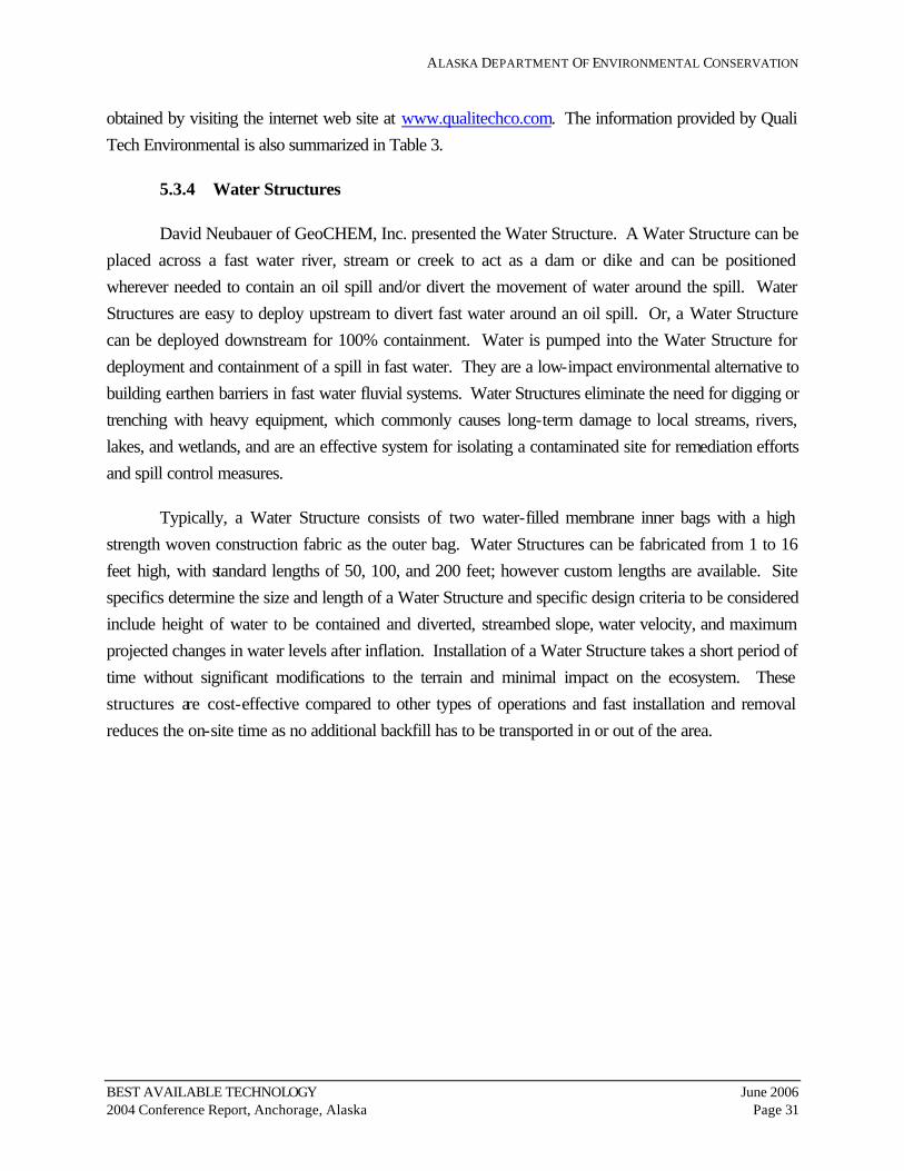
ALASKA DEPARTMENT OF ENVIRONMENTAL CONSERVATION
BEST AVAILABLE TECHNOLOGY June 2006 2004 Conference Report, Anchorage, Alaska Page 31
obtained by visiting the internet web site at www.qualitechco.com. The information provided by Quali Tech Environmental is also summarized in Table 3.
5.3.4 Water Structures
David Neubauer of GeoCHEM, Inc. presented the Water Structure. A Water Structure can be placed across a fast water river, stream or creek to act as a dam or dike and can be positioned wherever needed to contain an oil spill and/or divert the movement of water around the spill. Water Structures are easy to deploy upstream to divert fast water around an oil spill. Or, a Water Structure can be deployed downstream for 100% containment. Water is pumped into the Water Structure for deployment and containment of a spill in fast water. They are a low-impact environmental alternative to building earthen barriers in fast water fluvial systems. Water Structures eliminate the need for digging or trenching with heavy equipment, which commonly causes long-term damage to local streams, rivers, lakes, and wetlands, and are an effective system for isolating a contaminated site for remediation efforts and spill control measures.
Typically, a Water Structure consists of two water-filled membrane inner bags with a high strength woven construction fabric as the outer bag. Water Structures can be fabricated from 1 to 16 feet high, with standard lengths of 50, 100, and 200 feet; however custom lengths are available. Site specifics determine the size and length of a Water Structure and specific design criteria to be considered include height of water to be contained and diverted, streambed slope, water velocity, and maximum projected changes in water levels after inflation. Installation of a Water Structure takes a short period of time without significant modifications to the terrain and minimal impact on the ecosystem. These structures are cost-effective compared to other types of operations and fast installation and removal reduces the on-site time as no additional backfill has to be transported in or out of the area.

ALASKA DEPARTMENT OF ENVIRONMENTAL CONSERVATION
BEST AVAILABLE TECHNOLOGY June 2006 2004 Conference Report, Anchorage, Alaska Page 32
Information from GeoChem, Inc. regarding the Water Structure technology is included on the completed evaluation form in Appendix K. Additional information about GeoCHEM, Inc. can be obtained by visiting their internet web site at www.geocheminc.com. The information provided by GeoChem, Inc. is also summarized in Table 3.
5.4 Category 4: Viscous Oil Pumping Systems
There were three technologies presented at the BAT Conference for the Viscous Oil Pumping Systems category including: Foilex Pumps; GT-A Pumps; and Annular Water Injection.
5.4.1 Foilex Pumps
Mark Ploen of Quali Tech Environmental, a distributor of spill response and other equipment, presented the Foilex Twin Disc Screw (TDS) Pump. The TDS 150, 200 and 250 Foilex Pumps can be lowered into a storage tank or vessel containing extremely viscous oil. The submersible Foilex Pump can be used in offloading oil with extreme viscosity. Foilex Pumps have up to 70% higher capacity than any other traditional Positive Displacement Archimedean Screw (PDAS) pump design. The TDS design of the Foilex Pump makes these pumps more efficient for viscous liquids because the screw can turn at a slower rate for the same output capacity. The TDS design has two circular sealing discs fitted to each side of the pump screw, creating its positive displacement and required pressure. The stainless steel pump casings make them more resistant to wear and corrosive environments than carbon steel pumps.
Foilex TDS Pumps have, as an option, annular water injection flanges for steam, water, or other lubricating liquids and can reduce pressure drop up to 90% under certain conditions. Under test conditions, the pump using steam injection was able to move bitumen with a viscosity of 2 million centistokes. Steam pumped through the water collar actually warmed the oil and reduced the actual viscosity of the bitumen to 1.3 million centistokes. The Foilex TDS 150 pump is one of the only Archimedean screw pumps small enough to fit through a standard Butterworth hatch. Foilex Pumps can be used as transfer pumps or as a skimmer any place that transfer pumps and/or skimmers are currently being used.
Information from Quali Tech Environmental regarding the Foilex Pumps technology is included on the completed evaluation form in Appendix L. Additional information about Quali Tech Environmental can be obtained by visiting their internet web site at www.qualitechco.com. The information provided by Quali Tech Environmental is also summarized in Table 4.

ALASKA DEPARTMENT OF ENVIRONMENTAL CONSERVATION
BEST AVAILABLE TECHNOLOGY June 2006 2004 Conference Report, Anchorage, Alaska Page 33
5.4.2 GT-A Pumps
Jim Mackey of Lamor Corporation, LLC, presented the Lamor GT-A 20, 50 and 115 Positive Displacement Archimedes Screw (PDAS) Pumps. The submersible GT-A Pumps are portable, hydraulically-powered, and suitable for all fluids, including high viscosity oils, emulsions, and bitumen. The GT-A pump technology allows pumping in very cold conditions where oil is at extremely high viscosity or below its pour point. The pumps incorporate many new design features making them ideal for Alaska conditions to replace older system pumps for salvage offloading, oil skimming systems, tank cleaning, and other transfer operations. The GT-A Pump design uses a high torque hydraulic motor that delivers 20% higher discharge pressure than other pumps increasing its capacity to pump oil at extremely high viscosity. A GT-A Pump discharge pressure with a 6-inch hose can be as high as 180 pounds per square inch (psi) depending on which of the three GT-A pumps is used and the viscosity of the oil. The working pressure of the 6-inch hose typically used by the USCG is 150 psi. Hose connectors recommended for use are Hydrasearch split clamp type couplers with 225 psi working pressure.
The GT-A 20 is small and light enough to be carried under one arm and will fit into a Butterworth opening, allowing access into a wider range of vessel tanks and use in more remote locations. Because of their tight sealing, positive displacement design, they can pump water or extremely high viscosity oil with the same efficiency. The GT-A Pump technology has been tested by the Joint Viscous Oil Pumping System (JVOPS) committee for use in viscous oil pumping. The pumps are fitted with integral annular water injection on the inlet side of the pump, which allows hot water or steam to increase inflow to the pump with no external flanges, simultaneously providing water lubrication to reduce pressure in the oil delivery hose. The pumps have stainless steel wear plates to protect the aluminum pump housing and plate wheel cover, which is not available with other pumps.
GT-A pumps have previously been used in Alaska and would have improved response efforts in the Kuroshima grounding. This incident involved cold fuel oil and the built-in steam injection technology and high pressure capability would have improved the overall response.
Information from Lamor Corporation regarding the GT-A Pump technology is included on the completed evaluation form in Appendix M. Additional information about GT-A Pumps can be obtained by visiting the internet web site at www.lamor.com. The information provided by Lamor Corporation is also summarized in Table 4.

ALASKA DEPARTMENT OF ENVIRONMENTAL CONSERVATION
BEST AVAILABLE TECHNOLOGY June 2006 2004 Conference Report, Anchorage, Alaska Page 34
5.4.3 Annular Water Injection
Jim Mackey of Hyde Marine, Inc. also presented the Annular Water Injection (AWI) technology. Mr. Mackey discussed testing of this technology by the Joint Viscous Oil Pumping System (JVOPS) committee in December 2003 for use in viscous oil pumping. Hyde Marine has provided hundreds of PDAS pumps to responders in Alaska. PDAS pumps are viscous oil pumping systems but, like any mechanical equipment, they have their limitations. The AWI technology is used to improve inflow to PDAS pumps and to create a lubricating sleeve of water between viscous oil and the hose wall. The result is reduced friction and pressure in the discharge hose.
AWI technology allows pumping in conditions where there would likely be failure, as in Alaska where cold, harsh environments and remote locations complicate responses and the oil is below pour point. AWI’s technology and operational techniques allow any PDAS pump to transfer higher viscosity oils. AWI techniques for steam or hot water injection is an option to bulk heating and is a more portable and compact solution. Using steam injection, the AWI technology heats up the oil near the pump intake creating almost similar conditions as for local bulk heating. AWI techniques enable the PDAS pumps to transfer even the most extreme viscosity oils and emulsions at operational pumping rates over operational distances. The PDAS pumps will, in principle for each revolution, cut a segment or “thread” out of the pumped product and push it through the pump. There would still be stripes after pumping with no mixing and no emulsification.
Hydraulic power packs, hydraulic hose, high pressure discharge hose, steam/water pumps and delivery hose are also required but are normally found in a response inventory. Operating the lubricating water pump system during oil transfer operation adds some complexity to the overall operation but the benefits far outweigh the costs. This technology allows oil to be pumped that would otherwise not be pumpable.
Information from Hyde Marine regarding the Annual Water Injection technology is included on the completed evaluation form in Appendix N. Additional information about Hyde Marine can be obtained by visiting their internet web site at www.hydemarine.com. The information provided by Hyde Marine is also summarized in Table 4.
5.5 Category 5: Well Capping
There were two technologies presented at the BAT Conference for the Well Capping category including: the Abrasive Jet Cutter; and Voluntary Well Ignition and Capping While Burning.

ALASKA DEPARTMENT OF ENVIRONMENTAL CONSERVATION
BEST AVAILABLE TECHNOLOGY June 2006 2004 Conference Report, Anchorage, Alaska Page 35
5.5.1 Abrasive Jet Cutter
Terry Edwards of Halliburton, a manufacturer of jet cutters used by Boots & Coots Services, presented the Abrasive Jet Cutter. The Abrasive Jet Cutter, designed in 1991 for the well fires in Kuwait following Operation Desert Storm, can cut a well head off while the well is burning. The Abrasive Jet Cutter is easy to rig, comes with a self-contained mobile power unit, and is small enough to fit on a charter plane. When assembled, the Abrasive Jet Cutter is two units: the cutter and the hydraulic power pack.
The simplified version of the Abrasive Jet Cutter has scissor arms which hold the nozzle and allow it to track forward. The cutter consists of two opposing tungsten carbide nozzles, each tracked in a rectilinear direction. Each nozzle cuts through one half of the well head assembly or casing strings, with the rotary actuary allowing the cutter left and right movement. If the wellhead is damaged at an odd angle, you can position the cutter to make a straight cut. Knuckle joints are on a pivot point and have a hydraulic winch that can be remotely operated, allowing the cutter up and down movement. The rotary actuary allows more flexibility. One of the biggest obstacles is visibility on a fire. Often you can position the cutter on a flange and cut off the upper half of the flange so that the bolts fall out allowing the fire company to come in and push that piece of flange off, saving time for the fire companies. Abrasive slurry is pumped through the nozzles at a rate of 168 gallons per minute and at a pressure of 10,000 pounds per square inch. Once slurry is traveling through the nozzles, the remotely located hydraulic power pack is activated to start cutting the well head. Cutting speed is about one-half inch per minute, however, you can speed it up or slow it down. The Abrasive Jet Cutter is designed to cut the well while the blowout is on fire. To accomplish this, all hydraulic hoses are encased in a water protective jacket that can withstand temperatures in excess of 2,500°F. After the wellhead has been cut off and a venturi tube has been set in place, the fire will be vertical, allowing the firefighting capping crew to contain the blowout.
Additional resources for the Abrasive Jet Cutter include 20-40 frac sand, an Athey Wagon, and a D-8 bulldozer. The Abrasive Jet Cutter is positioned into a burning well using the Athey Wagon and a bulldozer. An Athey Wagon is currently on the North Slope and frac sand is available in Alaska through Halliburton.
Information from Boots & Coots Services regarding the Abrasive Jet Cutter technology is included on the completed evaluation form in Appendix O. Additional information about Boots & Coots Services can be obtained by visiting their internet web site at www.bncg.com. The information provided by Halliburton and Boots & Coots Services is also summarized in Table 5.

ALASKA DEPARTMENT OF ENVIRONMENTAL CONSERVATION
BEST AVAILABLE TECHNOLOGY June 2006 2004 Conference Report, Anchorage, Alaska Page 36
5.5.2 Voluntary Well Ignition and Capping While Burning
Larry Flak, former International Well Control Engineering Manager for Boots & Coots Services, presented Voluntary Well Ignition and Capping While Burning. Often, when a blowout cannot be controlled and a spill cannot be contained, voluntary ignition is the only option. Once a blowout occurs in the well and the fire is under control, smoke is no longer an issue for implementing the well capping procedures. Part of the strategy of voluntary ignition is how the well is approached and ignited.
Mr. Flak showed a video of a recent blowout in Roland Hills, Mississippi, where a well collapsed while running a completion string and the blowout preventor (BOP) failed to seal because of an obstruction. Once the drill crew realized that they could not control the flow, they ignited the well. With the Roland Hills incident an ICS system was implemented, similar to one used on the North Slope. Several federal agencies were present to monitor the well kill including the EPA, MMS, and the U.S. Coast Guard. Large equipment was mobilized to the blowout site to remove the rig. Heat shelters were fabricated from reflective metal to provide refuge. A lined pit was created for cooling water and removal of the rig began. The BOPs were destroyed by the heat and therefore removed. Clearing a path among the refuse, so that the jet cutter had access to the wellhead, took approximately 3 days. Establishing a water supply was essential and at this site a water treatment plant was built so that the water didn’t become an added hazard. In Arctic locations, where water may not be readily available, Boots & Coots rely on galvanized roofing tin, shiny side out, because it is extremely effective and readily available. Annual drills are conducted on the North Slope to ensure supply availability. It is critical to do as much work dry as possible so that mud holes are not created, especially in frozen tundra.
The Athey Wagon is used to back the jet cutter up to the well to cut the wellhead and bulldozers are used to knock over the BOPs. A Venturi tube is used over the fires to make it flow vertically, creating a vacuum at the end of the tube to push the fire higher. The crew is able to get closer after the Venturi tubes are installed and make the final cuts. The well capping stack is backed into the fire with a bulldozer and cables are run between the flange on the blowout and the mating flange on the capping stack. This procedure is referred to as “snubbing the flanges.” The crew wears multiple layers of wet cotton. In the Arctic, bunker gear is required and work is conducted under heat shielding.
Access to remote locations is not a problem as equipment can be mobilized by airfreight, ice bridges, or barges, depending on the time of year. Often equipment already on hand is used in the well kill operation. Boots & Coots have not experienced a well capping problem that they were not able to solve.

ALASKA DEPARTMENT OF ENVIRONMENTAL CONSERVATION
BEST AVAILABLE TECHNOLOGY June 2006 2004 Conference Report, Anchorage, Alaska Page 37
Information from Boots & Coots Services regarding Voluntary Blowout Ignition and Capping While Burning is included on the completed evaluation form in Appendix P. Additional information about Boots & Coots can be obtained by visiting their internet web site at www.bncg.com. The information provided by Boots & Coots Services is also summarized in Table 5.
5.6 Category 6: Source Control Technologies
There were two technologies presented at the BAT Conference for the Source Control Technologies category including: Pipeline Clamps; and Well Blowout Control.
5.6.1 Pipeline Clamps
Pete Haburt, Sales Technician for PLIDCO, presented PLIDCO Pipeline Clamps and fittings. PLIDCO’s mechanical repair sleeves offer alternatives to in-service welding. A mechanical repair sleeve is defined by API as “a split mechanical fitting which encapsulates and seals off an area on the pipeline and can be classified as either structural or non-structural.” Basically, PLIDCO Pipeline Clamps are considered non-structural. Once welded, PLIDCO Pipeline Clamps are considered structural. PLIDCO products include leak-enclosure fittings, connector fittings, hot-tapping/line-plugging products, and custom-designed fittings.
PLIDCO Pipeline Clamps are designed for pressures up to 10,000 pounds per square inch (psi) and temperatures from minus 250°F to 900°F. PLIDCO Pipeline Clamps are available in pipe sizes from 1.5 inch through 48 inches. PLIDCO Pipeline Clamps are designed to repair pipelines, most without shutdown, to keep downtime to a minimum. PLIDCO Pipeline Clamps have been used worldwide for pipe repair and maintenance and in a variety of applications both onshore and offshore. Applications include oil gas, water, chemical, steam, slurry and other piping systems. PLIDCO Pipeline Clamps can be back welded with the line in operation or bolted only for weld-hazardous or weld-difficult areas.
Some considerations in determining whether a repair sleeve is appropriate include the diameter of the pipe, length between seals, pressure and temperature, seal material, whether its structural or non-structural, if the pipe is deformed (can make variations to encompass entire pipe and close it off if deformed), and proper enclosures.
Proper storage is critical to the shelf life of PLIDCO Pipeline Clamps. Products should be stored in a cool dry place, away from direct sunlight or heat, and in an enclosed area to protect the seals and gaskets from the environment. Depending on proper storage, the shelf life for the PLIDCO Pipeline Clamp seals and gaskets can range from 2 to 5 years for Buna-N fittings; 5 to 10 years for Hycar and Neoprene; and up to 20 years for Aflas, Silicone, and Viton fittings.

ALASKA DEPARTMENT OF ENVIRONMENTAL CONSERVATION
BEST AVAILABLE TECHNOLOGY June 2006 2004 Conference Report, Anchorage, Alaska Page 38
Information from PLIDCO regarding Pipeline Clamps is included on the completed evaluation form in Appendix Q. Additional information about PLIDCO can be obtained by visiting their internet web site at www.plidco.com. The information provided by PLIDCO is also summarized in Table 6.
5.6.2 Well Blowout Control
John W. Wright presented three sub-technologies for Well Blowout Control including Well Control Management, OLGA2000 Well Kill Hydraulic Simulation Software, and Relief Wells.
Well Control Management: John Wright Co. started developing the Well Control Management program about 10 years ago. They have used Well Control Management for operators all over the world to develop risk management, contingency and response plans both onshore and offshore. Well Control Management is commercially available for plan holders in Alaska and can be staged in Alaska if John Wright Co. can find the qualified person(s) to train. Initial work would include documenting processes, defining resources, developing risk assessments, training, writing response plans, and defining controls. All processes and procedures for well blowout management will need incorporation into the safety policies of the operator.
The Well Control Management program software manages response actions; documents and databases initial actions both at the location and at the office; develops team organizations for tactical and strategic planning; lists equipment and resource requirements; provides processes and tools for each team member to accomplish their jobs in the most efficient manner; tracks and documents progress; provides meeting schedules and agendas; and provides flowcharts, decision trees and milestones. The Well Control Management system also provides procedures to help responders decide when and how to safely ignite a well depending upon its location, onshore or offshore, the flow rates, the time of year, etc. Well Control Management is a systematic process to help identify hazards and assess their consequences; identify what controls are in place to prevent and mitigate blowouts; assess the risk and determine if the risk should be mitigated further or the well plugged or project cancelled before it is drilled; determine what controls will best mitigate the risk (e.g. better training or better design); define response actions for personnel on site and responsible personnel offsite; and provide guidelines for initial planning and strategic planning cycles.
OLGA2000 Well Kill Hydraulic Simulation Software: OLGA2000 has been used in hundreds of blowout contingency plans and in actual blowouts all over the world since 1989. Hydraulic modeling drives every aspect of blowout control operations from well capping to relief well intervention to underground blowouts. OLGA2000 can perform well diagnostics, determine blowout rates for oil, gas, and water ratios; tune model to production data; evaluate shut-in pressures; and determine if well should be capped, bullheaded or diverted for a snub kill. OLGA2000 evaluates pressures during snubbing or

ALASKA DEPARTMENT OF ENVIRONMENTAL CONSERVATION
BEST AVAILABLE TECHNOLOGY June 2006 2004 Conference Report, Anchorage, Alaska Page 39
off bottom kills; where to perforate pipe; mud weight to use; mud volume to use; and pump hydraulic horsepower requirement (rate and duration). Many blowout simulations are performed via email and internet. Without OLGA2000 simulations, well control operations could be delayed for literally weeks or months due to bad decisions.
For relief wells, OLGA2000 can determine pipe sizes; pressure requirements; temperature effects; intersection depth; kill plant requirements; hookups to rig; type of rig required; and for offshore blowouts, the type of barges required for holding mud volumes, pumps, and other equipment. OLGA2000 evaluates combustion efficiency and flow rates of well blowouts based on flame height, fluid composition, and heat radiation.
OLGA2000 is not for sale, but offered as a service, and simulations are performed by trained specialists. The John Wright Co. has 15 years experience in using the OLGA2000 software for modeling well blowouts and are the only company who specialize exclusively in blowout and kill simulations using this technology.
Relief Well Intervention: The John Wright Co. is a world leader in Relief Well intervention and has planned and executed 32 relief well projects since 1986 including the Alaska Steelhead blowout in 1988. Relief Well technology involves drilling to a predetermined intersection depth and killing the well by pumping reactant fluids down the relief well. John Wright Co. partners with Vector Magnetics who have developed a unique method for homing-in to intersect wells using a rotating magnet in the bit of the relief well and applying an electric current at the target well.
In some instances, a Relief Well is the only practical way to control a well offshore, particularly for close wellhead bays on the platforms in Cook Inlet, subsea wells, casing failures, or broaches. If a well blowout cannot be safely capped while on fire, a relief well can be drilled to control the well while the blowout is left to burn. Besides the drilling rig, John Wright Co. will need conductor wire line for ranging; continuous gyro survey; directional drilling tools; kill fluid pumping plant; large volume mud storage; and accommodations for six engineers or specialists. The cost for a Relief Well will typically range from $1 million to $5 million.
Information from John Wright regarding Well Blowout Control including Well Control Management, OLGA2000 Well Kill Hydraulic Simulation Software, and Relief Wells is included on the completed evaluation form in Appendix R. Additional information about John Wright Company can be obtained by visiting their internet web site at www.jwco.com. The information provided by John Wright is also summarized in Table 6.

ALASKA DEPARTMENT OF ENVIRONMENTAL CONSERVATION
BEST AVAILABLE TECHNOLOGY June 2006 2004 Conference Report, Anchorage, Alaska Page 40
6.0 ADEC FINDINGS ON BEST AVAILABLE TECHNOLOGIES
The ADEC assembled an Evaluation Committee from the department to attend the BAT Conference on May 27 and 28, 2004, and to evaluate the technology presentations. Members of the Evaluation Committee were selected from the Division of Spill Prevention and Response (SPAR) Industry Preparedness Program (IPP) and Prevention and Emergency Response Program (PERP). The Evaluation Committee also included Spill Technology Expert, Dr. Robert Hiltabrand. The members of the Evaluation Committee for each of the six categories are indicated in the following sections.
Written findings for the technologies in each category were received from the Evaluation Committee. The following sections present the findings of the Evaluation Committee for the technologies presented at the BAT Conference. These findings identify the evidence that clearly and convincingly support the determination that the vendor technology is a proven technological breakthrough in oil discharge containment, control, or cleanup equipment. They also identify specific operations, geographical locations, or physical environments where the technologies could be applied.
It is emphasized that the BAT Conference held on May 27 and 28, 2004, was about spill prevention and response technologies considered to be the “best” and that are “available”. In many cases, the “best” technology will be a proven technology that may not be a new technological breakthrough. Additionally, not all Technology Providers in the six categories could attend the BAT Conference, although all were invited. All Technology Providers who requested to be included in the BAT Conference during the open solicitation period were included. However, some other technologies considered “best” in a specific category were just not “available” for the BAT Conference.
6.1 Category 1: Leak Detection Systems for Crude Oil Transmission Pipelines
The ADEC Evaluation Committee for Category 1 included: Sam Saengsudham (Chair), Wade Gilpin, Dr. Robert Hiltabrand, Becky Lewis, and Ted Moore. The pipeline leak detection requirements are specified in 18 AAC 75.055(a). The requirements state that a crude oil transmission pipeline must be equipped with a pipeline leak detection system (PLDS) capable of promptly detecting a leak including:
• If technically feasible, the continuous capability to detect a daily discharge equal to not more than one percent of daily throughput;
• Flow verification through an accounting method, at least once every 24 hours; and • For a remote pipeline not otherwise directly accessible, weekly aerial surveillance, unless
precluded by safety or weather conditions.

ALASKA DEPARTMENT OF ENVIRONMENTAL CONSERVATION
BEST AVAILABLE TECHNOLOGY June 2006 2004 Conference Report, Anchorage, Alaska Page 41
There were five methodologies, representing two technologies, presented at the BAT Conference. Four of these methodologies, ATMOS™ Pipe, LeakNet™, WaveAlert®, and Sonilocate®/Ultrasonic Flowmeters use proprietary alert algorithm methods as part of internally-based computational pipeline monitoring (CPM) systems. One methodology, duoThane™, is an optical-based system that detects leaks without performing computation on field parameters for inferring a spill.
The difference between the individual CPM methodologies is their alert algorithm. However, only limited information was provided on the alert algorithm themselves. Therefore, it is not possible to make precise comparative assessments to determine which technology is the best available. This statement does not question the validity and/or effectiveness of the CPM methodologies as the evaluations are based on limited reviews of the information provided by each submitter as listed in Table 1. The evaluations are not substitutions for a detailed engineering assessment in selecting a pipeline leak detection system. Such a process customarily begins with a specific pipeline system rather than a technology. This assessment is based on each evaluator’s best professional judgment and expertise without the benefits of having a specific pipeline system with which to start.
Ideally, leak detection vendors could state exactly how their systems would perform on a given pipeline configuration prior to installation. In practice, predicting performance is often difficult due to variability in product characteristics (density and viscosity), pipeline parameters (diameter, length, and elevation profile), and process instrumentation variables (flow, temperature, and pressure). Operators need to allow the PLDS vendors an opportunity to discover the characteristics of their pipeline to be able to convey to the operator the capabilities of their product. Companies considering installing a PLDS in Alaska should consult the Technical Review of Leak Detection Technologies, Volume 1, Crude Oil Transmission Pipelines, September 30, 1999, prepared for ADEC.
Since the effectiveness of the leak detection system for each regulated pipeline is subject to verification by ADEC, it is the responsibility of the operators to select the most appropriate technology/system to demonstrate compliance with, and satisfy, the regulatory requirements in 18 AAC 75.055(a). It should be noted that the ability or effectiveness of alarm algorithms does not significantly depend on local climate.
6.1.1 ATMOS™ Pipe (ATMOS International)
ATMOS™ Pipe uses internal CPM technology including modified volume balance and statistical analysis and, specifically, Sequential Probability Ratio Test (SPRT). ATMOS International claims that their system is the best in use for crude oil transmission pipelines because it: does not generate false alarms due to operational changes; has the capability of detecting leaks under transient conditions; has no special requirements in SCAN rate; and, works with existing SCADA systems.

ALASKA DEPARTMENT OF ENVIRONMENTAL CONSERVATION
BEST AVAILABLE TECHNOLOGY June 2006 2004 Conference Report, Anchorage, Alaska Page 42
ATMOS™ Pipe can decrease the spill volume by a reduction in detection time and high confidence level in a real leak when an alarm is generated. The ATMOS™ Pipe technology information provided by ATMOS International is presented in Table 1 and Appendix A. ATMOS™ Pipe has demonstrated acceptable performance in a variety of crude oil transmission pipeline configurations throughout the world. ATMOS™ Pipe was selected for the Chad Development Project and the Baku, Azerbaijan to Cehlan, Turkey Project.
Summary: ATMOS™ Pipe was found to meet the general criteria for BAT in 18 AAC 75.445(k) and is capable of satisfying the requirements of 18 AAC 75.055(a) if properly selected and configured for certain specific pipeline system configurations. As such, it is expected that operators include ATMOS™ Pipe during the evaluation of pipeline leak detection system alternatives to find the optimum system for their respective pipeline configuration(s).
6.1.2 duoThane™ (Ophir Corporation)
Ophir Corporation presented duoThane™, an optical remote sensing device using the broadband infrared light concept. Table 1 and Appendix B present the technology information provided by Ophir Corporation. While appearing to be an emerging technology, duoThane™ has not been used for leak detection in crude oil transmission pipelines.
DuoThane™ could be beneficial with its high sensitivity to petroleum hydrocarbon vapors, early leak detection, and accurate leak location capabilities. Ophir Corporation indicates that duoThane™ is intended for use specifically for spills under waterways. However, pipeline operators could consider augmenting a CPM-based systems with the optical remote sensing provided by duoThane™, especially for above and below ground pipeline segments that traverse environmentally sensitive areas. DuoThane™, if properly selected and configured for certain specific pipeline system configurations, has the potential for providing the continuous capability to detect a leak of much less than one percent of daily throughput.
Summary: For enhanced capabilities, operators could consider augmenting a CPM-based system with the optical remote sensing provided by duoThane™ for pipeline segments that traverse environmentally sensitive areas, and/or certain waters of the State, such as high consequence waterways.
6.1.3 LeakNet™ (Ed Farmer & Associates)
LeakNet™ uses Internal CPM technology including Modified Volume Balance (Masspack™), Pressure/Flow Monitoring, Statistical Analysis (Flowing PPA™), Acoustic/Negative, and Pressure Wave rarefaction (Flowing PPA™). LeakNet™ has demonstrated acceptable performance in a

ALASKA DEPARTMENT OF ENVIRONMENTAL CONSERVATION
BEST AVAILABLE TECHNOLOGY June 2006 2004 Conference Report, Anchorage, Alaska Page 43
variety of pipeline configurations including above ground, below ground and subsea applications. The LeakNet™ technology information provided by Ed Farmer & Associates is presented in Table 1 and Appendix C. LeakNet™ is currently monitoring many pipelines in Alaska and has been selected as BAT for the NorthStar crude oil pipeline.
Summary: LeakNet™ was found to meet the general criteria for BAT in 18 AAC 75.445(k) and is capable of satisfying the requirements of 18 AAC 75.055(a) if properly selected and configured for certain specific pipeline system configurations. As such, it is expected that operators include LeakNet™ during the evaluation of pipeline leak detection system alternatives to find the optimum system for their perspective pipeline configuration(s).
6.1.4 WaveAlert® (Acoustic Systems Inc.)
WaveAlert® Acoustic Leak Detection System uses Acoustic/Negative Pressure Wave technology and methods. WaveAlert® has demonstrated acceptable performance in a variety of pipeline configurations and is recognized as one of the most effective PLDS for multiphase flow, such as crude oil, gas, and water, in both offshore and onshore pipelines. WaveAlert® has been used for automatic valve shut-off upon detecting leaks. WaveAlert® is the only known system with a proven record of actually detecting a leak and automatically shutting off a pipeline within one to two minutes of leak occurrence. WaveAlert® has demonstrated acceptable performance in a variety of crude oil transmission pipeline configurations throughout the world. Table 1 and Appendix D present the technology information provided by Acoustic Systems Inc. WaveAlert® was selected for use for the Seal Project in Aracaju, Brazil.
Summary: WaveAlert® was found to meet the general criteria for BAT in 18 AAC 75.445(k) and is capable of satisfying the requirements of 18 AAC 75.055(a) if properly selected and configured for certain specific pipeline system configurations. As such, it is expected that operators include WaveAlert® during the evaluation of pipeline leak detection system alternatives to find the optimum system for their perspective pipeline configuration(s).
6.1.5 Sonolicate®/Ultrasonic Flowmeters (Controlotron)
Sonolicate® is a modified volume balance alert algorithm. Sonolicate® is being used in various pipeline systems with some degree of success. As with all CPM based leak detection systems, Sonolicate® performance depends heavily on each pipeline system configuration and field instruments. One notable difference from other CPM based algorithms is that Sonolicate® is usually packaged with Controlotron Ultrasonic Flowmeters.

ALASKA DEPARTMENT OF ENVIRONMENTAL CONSERVATION
BEST AVAILABLE TECHNOLOGY June 2006 2004 Conference Report, Anchorage, Alaska Page 44
The Controlotron Ultrasonic Flowmeter is considered a field instrument that provides data to be used by a CPM-based systems’ inference engine for use with the respective alert algorithms. Ultrasonic Flowmeters have been in operation on the North Slope since 1983, are already in use as a secondary device on the Alyeska Trans-Alaska Pipeline System, and have been in use at British Petroleum production sites in outdoor environments since 1985. They are an alternative to intrusive positive displacement meters, turbine meters, and Coriolis meters. The Sonolicate®/Ultrasonic Flowmeter technology information provided by Controlotron is presented in Table 1 and Appendix E. Controlotron’s Sonolicate®/Ultrasonic Flowmeters have demonstrated acceptable performance in a variety of crude oil transmission pipeline configurations throughout the world and were selected as BAT for the Trans-Alpine Pipeline which runs from Trieste, Italy, over the Alps to Munich, Germany.
Summary: Sonolicate®/Ultrasonic Flowmeters systems were found to meet the general criteria for BAT in 18 AAC 75.445(k) and are capable of satisfying the requirements of 18 AAC 75.055(a) if properly selected and configured for certain specific pipeline configuration. As such, it is expected that operators include Ultrasonic Flowmeter during the evaluation of pipeline leak detection system alternatives to find the best for their perspective pipeline system configurations(s).
6.2 Category 2: Secondary Containment Liners for Oil Storage Tanks
The ADEC Evaluation Committee for Category 2 included: Bob Dreyer (Chair), Dr. Robert Hiltabrand, Natalie Howard, Ted Moore, Laurie Silfven, and Elizabeth Stergiou. A description of the secondary containment liner (SCL) requirements can be found in 18 AAC 75.075.
6.2.1 Petrogard VI and X (MPC Containment)
MPC Containment Systems of Chicago gave a presentation on products they manufacture or install. MPC focused on Petrogard VI and X which are proven technologies in use throughout Alaska, Canada, and Greenland. Table 2 and Appendix F present the technology information provided by MPC. Petrogard VI and Petrogard X are flexible, have a low rate of thermal expansion, are UV stable, are usable for cold weather applications (above 20°F), and are able to hold products for long periods of time. Petrogard VI and Petrogard X have permeability which meet the definition of “sufficiently impermeable” in 18 AAC 75.990(124). Pillow tanks have been made from Petrogard X liner where the tanks were filled continuously with various petroleum-based fuels for 10 years. Both liners are compatible with crude oil, diesel fuel, fuel oil, gasoline, and aviation gas.
The limitations of Petrogard VI and X include welding around penetrations. These issues can be resolved by use of mechanical battening at concrete, liner penetrations and connections with other materials; banding at pipe and pipe supports; urethane caulk to connect Petrogard X to metal; and

ALASKA DEPARTMENT OF ENVIRONMENTAL CONSERVATION
BEST AVAILABLE TECHNOLOGY June 2006 2004 Conference Report, Anchorage, Alaska Page 45
appropriate designs to allow performance of the required 5 year external inspection in accordance with API 653. Another weak point in Petrogard VI and X is that they get stiff at about 20°F. This can be resolved by planning secondary containment liner installations during ambient temperatures above 20°F.
Summary: MPC Containment Systems’ presentation did not present anything new in terms of “breakthrough technology.” However, Petrogard VI and X have been tried and tested in Alaska’s extreme environment and, if properly selected for certain specific secondary containment liner applications, could be BAT satisfying the requirements found in 18 AAC 75.075 and 18 AAC 75.990(124).
6.2.2 GSE HDPE Liners (Polar Supply Company)
Polar Supply Company of Anchorage gave a presentation on products they distribute or install. Polar Supply focused on GSE HDPE liners which are in use on over 12 oil storage tank projects in Alaska, including in Prudhoe Bay. HDPE liners have high tensile strength, are flexible, are UV stable, and generally are good for cold weather applications. HDPE liners can be fabricated at thicknesses ranging from 27 mil to 90 mil and can be used in projects with temperatures ranging from -130°F to 302°F.
Chemical resistance is limited and the liner material is not resistant to gasoline constituents. The GSE HDPE liner technology information provided by Polar Supply Company is presented in Table 2 and Appendix G. Polar Supply Company mentioned crude oil had no effect on permeability. If there is a spill the GSE HDPE liners will swell, and if the substance is cleaned up prior to breach of permeability, the fabric will resume original shape. Polar Supply Company indicates that the breakthrough time for pooled gasoline occurs at 72 hours, which does not appear to meet the definition of “sufficiently impermeable” in 18 AAC 75.990(124). For a secondary containment system, sufficiently impermeable typically means a liner must be capable of containing spilled oil until it can be detected and cleaned up.
The cost per square foot for the installation of GSE HDPE liners is approximately $1.00 to $1.50 per square foot for material and greater than $2.00 per square foot including installation. The cost will depend on liner thickness and size, complexity, and number of penetrations specific to the project. GSE HDPE liners are best when used for large jobs as the cost of liner will offset the high cost of equipment needed for installation.
Weak points in GSE HDPE liners include low chemical resistance to gasoline product. There are also concerns over wrinkle problems due to thermal contraction and expansion and where liners are connected to tanks, piping, and supports. Wrinkle problems must be taken into account during

ALASKA DEPARTMENT OF ENVIRONMENTAL CONSERVATION
BEST AVAILABLE TECHNOLOGY June 2006 2004 Conference Report, Anchorage, Alaska Page 46
installation and repair by determining the appropriate amount of slack or extra liner needed to allow for thermal expansion and contraction. Liner connection issues can be resolved by using mechanical battening at concrete, liner penetrations and connections with other materials; banding at pipe and pipe supports; appropriate adhesives; specialized equipment and/or personnel to perform installation and/or repair work; and appropriate designs to allow performance of the required 5 year external inspection in accordance with API 653.
Summary: Polar Supply Company’s presentation did not present anything new in terms of “breakthrough technology.” However, GSE HDPE liners have been tried and tested and, if properly selected for certain specific secondary containment liner applications, could be BAT satisfying the requirements found in 18 AAC 75.075.
6.3 Category 3: Fast Water Booming
The ADEC Evaluation Committee for Category 3 included: Bill Hutmacher (Chair), John Brown, Tom DeRuyter, Marty Farris, Dr. Robert Hiltabrand, Becky Lewis, Ed Meggert and Harry Young. Response planning standards and time limitations for containment, control and cleanup of oil discharged to open waters in Alaska are described in 18 AAC 75.430 - 18 AAC 75.442. The types and amounts of boom, boom connectors, and anchorage devices used for fast water booming must be of the appropriate design for the particular oil product, type of environment, and environmental conditions experienced at the facility or operation. As described in 18 AAC 75.445(g)(3), the boom must be of sufficient length to mount an effective response to the response planning standard volume for each type of facility or operation. In fast water environments, an operator of a petroleum-handling facility or operation may be unable to mount a mechanical response to a discharge event using conventional boom equipment. If fast water booming techniques are used, the limitations of conventional boom equipment may be reduced.
6.3.1 NOFI Current Buster (AllMaritim)
The NOFI Current Buster is an innovative technology that has a variety of applications in Alaska coastal and river environments. The simplicity of the system is a strong point. Table 3 and Appendix H present the technology information provided by AllMaritim. As the oil/water mixture moves through the device, oil is collected and a large amount of the water is shed. The oil and remaining water mixture is accumulated in a separator. The separated oil can be pumped from the separator by using a wide variety of oil recovery devices. The oil separator also has an overpressure mechanism which allows the separated water to be continually discharged through the boom separator. The Current Buster can be deployed as a stationary recovery device in fast water situations or as part of a vessel-based sweep system, with towing speeds up to 3.5 knots. This is a real advantage because the

ALASKA DEPARTMENT OF ENVIRONMENTAL CONSERVATION
BEST AVAILABLE TECHNOLOGY June 2006 2004 Conference Report, Anchorage, Alaska Page 47
vessels are not limited to the usual 1 knot towing speed to maintain containment. Tests at OHMSETT have demonstrated that the Current Buster, being towed at 3.5 knots, can recover over 90% oil in calm waters and 70% oil in choppy waters. It has also been effectively used in actual responses involving diesel in Alaska and heavier oil in Norway. Another advantage over conventional boom systems is that the Current Buster can be turned easily 180 degrees without losing contained oil. The separator’s eight-foot draft may limit use of the Current Buster in some of the river areas; however, as long as there is enough depth for the separator, the system may still be used effectively. Its use in roadless areas may also be limited by the inability to deliver the containerized system to the deployment site.
Summary: The NOFI Current Buster was found to meet the general criteria for BAT in 18 AAC 75.445(k) and is considered a proven breakthrough technology which would be an effective addition to any C-Plan holder’s toolbox, as they determine the right system to meet the applicable response planning standards
6.3.2 Boom Vane (ORC-AB)
The Boom Vane is a very effective device that may be employed with containment booms up to 18 inches in a wide variety of configurations for river and open water (coast/offshore) response situations, including collection, deflection, and exclusion booming. The Boom Vane river system’s shallow draft and light weight assembly makes it especially attractive for use with booms deployed from shore. It can be used to deploy up to 500 feet of 18-inch boom from shore. The deeper draft ocean system is better suited for vessel-based responses. The Boom Vane can be used to move boom away from ice as necessary, and to properly position boom for maximum effectiveness in currents up to 5 knots. It eliminates the need for a second vessel to tow boom in a U or J configuration, minimizes the number of people needed to operate a boom system after deployment from shore, and requires no buoy anchors or power support. The Boom Vane technology information provided by ORC-AB is presented in Table 3 and Appendix I. With the significant characteristics described above, the Boom Vane would be a real “force multiplier.”
Summary: The Boom Vane was found to meet the general criteria for BAT in 18 AAC 75.445(k) and is considered a proven breakthrough technology that would provide a very effective addition to any C-Plan holder’s toolbox. Use of the Boom Vane will make it easier and less dangerous to respond to oil spills in fast water environments in Alaska and has the potential to enhance the C-Plan holders’ ability to meet the requirements of the response planning standards.
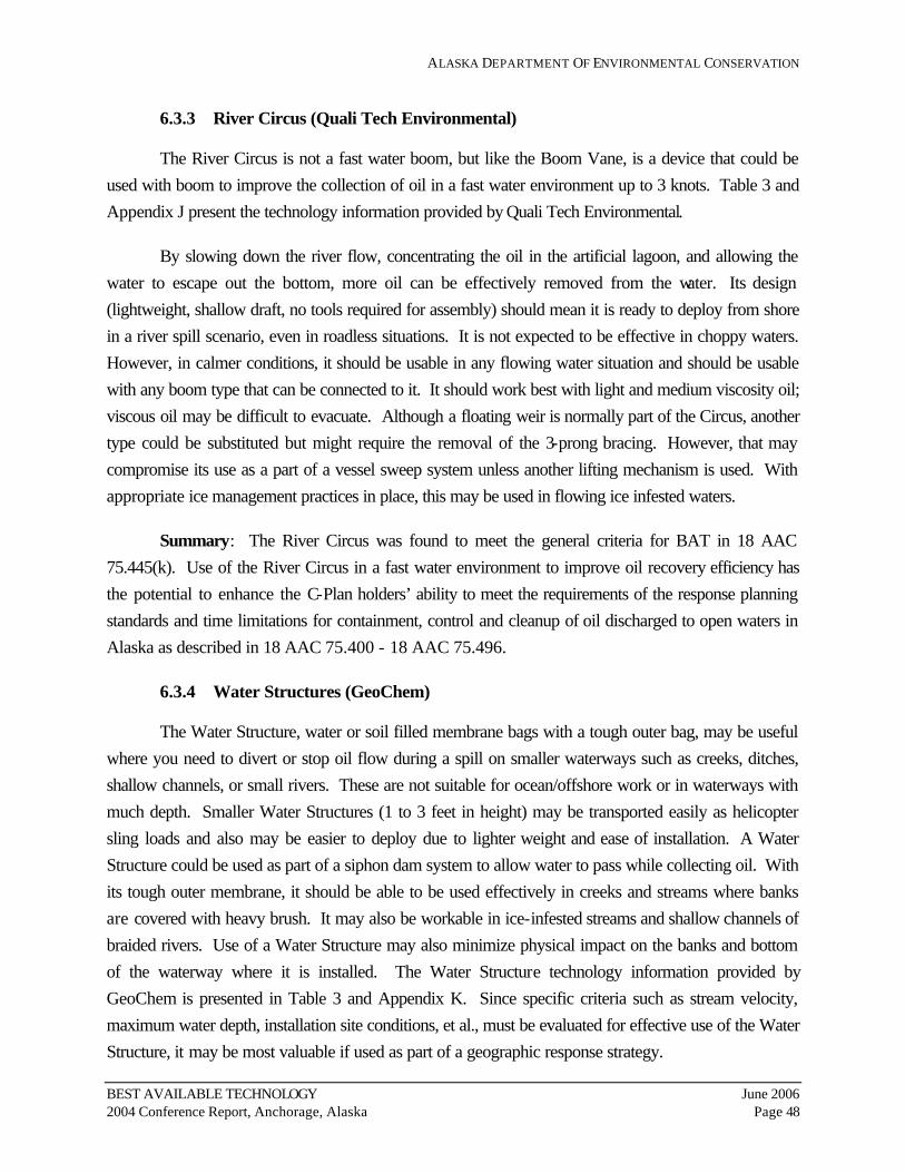
ALASKA DEPARTMENT OF ENVIRONMENTAL CONSERVATION
BEST AVAILABLE TECHNOLOGY June 2006 2004 Conference Report, Anchorage, Alaska Page 48
6.3.3 River Circus (Quali Tech Environmental)
The River Circus is not a fast water boom, but like the Boom Vane, is a device that could be used with boom to improve the collection of oil in a fast water environment up to 3 knots. Table 3 and Appendix J present the technology information provided by Quali Tech Environmental.
By slowing down the river flow, concentrating the oil in the artificial lagoon, and allowing the water to escape out the bottom, more oil can be effectively removed from the water. Its design (lightweight, shallow draft, no tools required for assembly) should mean it is ready to deploy from shore in a river spill scenario, even in roadless situations. It is not expected to be effective in choppy waters. However, in calmer conditions, it should be usable in any flowing water situation and should be usable with any boom type that can be connected to it. It should work best with light and medium viscosity oil; viscous oil may be difficult to evacuate. Although a floating weir is normally part of the Circus, another type could be substituted but might require the removal of the 3-prong bracing. However, that may compromise its use as a part of a vessel sweep system unless another lifting mechanism is used. With appropriate ice management practices in place, this may be used in flowing ice infested waters.
Summary: The River Circus was found to meet the general criteria for BAT in 18 AAC 75.445(k). Use of the River Circus in a fast water environment to improve oil recovery efficiency has the potential to enhance the C-Plan holders’ ability to meet the requirements of the response planning standards and time limitations for containment, control and cleanup of oil discharged to open waters in Alaska as described in 18 AAC 75.400 - 18 AAC 75.496.
6.3.4 Water Structures (GeoChem)
The Water Structure, water or soil filled membrane bags with a tough outer bag, may be useful where you need to divert or stop oil flow during a spill on smaller waterways such as creeks, ditches, shallow channels, or small rivers. These are not suitable for ocean/offshore work or in waterways with much depth. Smaller Water Structures (1 to 3 feet in height) may be transported easily as helicopter sling loads and also may be easier to deploy due to lighter weight and ease of installation. A Water Structure could be used as part of a siphon dam system to allow water to pass while collecting oil. With its tough outer membrane, it should be able to be used effectively in creeks and streams where banks are covered with heavy brush. It may also be workable in ice-infested streams and shallow channels of braided rivers. Use of a Water Structure may also minimize physical impact on the banks and bottom of the waterway where it is installed. The Water Structure technology information provided by GeoChem is presented in Table 3 and Appendix K. Since specific criteria such as stream velocity, maximum water depth, installation site conditions, et al., must be evaluated for effective use of the Water Structure, it may be most valuable if used as part of a geographic response strategy.

ALASKA DEPARTMENT OF ENVIRONMENTAL CONSERVATION
BEST AVAILABLE TECHNOLOGY June 2006 2004 Conference Report, Anchorage, Alaska Page 49
Summary: The Water Structure was found to meet the general criteria for BAT in 18 AAC 75.445(k) when used to divert or stop oil flow during a spill on fast water in smaller waterways. Use of the Water Structure could increase the efficiency of C-Plan holders to meet the requirements of 18 AAC 75.400 - 18 AAC 75.496. Planners must develop scenarios, tactics, and deployment strategies appropriate for each different geographic response strategy.
6.4 Category 4: Viscous Oil Pumping Systems
The ADEC Evaluation Committee for Category 4 included: Bob Flint (Chair), John Brown, Tom DeRuyter, Wade Gilpin, Dr. Robert Hiltabrand, Ed Meggert, Laurie Silfven, Elizabeth Stergiou, and Harry Young.
As established under 18 AAC 75.430 - 18 AAC 75.442, the number and size of pumps to be used in a cleanup response must be appropriate and adequate for recovery of the response planning standard volume of the type of oil discharged within the planning standard time limit for cleanup. The equipment types must be compatible with each other as necessary to ensure an efficient response. Previous response activities in Alaska have shown that an appropriate viscous oil pumping system is needed to pump cold crude oil, oil emulsions, and heavy fuel oil.
6.4.1 Foilex Pumps (Quali Tech Environmental)
The Foilex Pump is a submersible Positive Displacement Archimedes Screw Pump (PDAS), with relatively small size and large displacement. The Foilex Pump is efficient and appears to be well-built. The twin disc screw (TDS) design allows for more efficient pumping of viscous liquids since the screw can turn at a slower rate for the same output capacity as other PDAS pumps. This allows more time for viscous liquids to flow to the pump. Another advantage of this pump is the exposed screw which provides 360° inlet access for oil to enter the screw portion of the pump. The smallest of the three Foilex Pumps, the TDS 150, will operate through a Butterworth opening. Foilex TDS Pumps can be used as transfer pumps or as a skimmer component and can handle debris up to 2 inches in diameter. Table 4 and Appendix L present the technology information provided by Quali Tech Environmental.
The PDAS system has a greater ability to allow heavy oils to be removed from risk of further environmental damage than would be achievable with other pump technologies. The Foilex Pump PDAS has been successfully used in environments comparable with Alaska. While the system has not been used in extreme cold weather, it has been successfully operated in the near-freezing range. The Foilex Pump with water or steam injection ports, is a breakthrough technology that increases the pumping rate over suction pumps or systems without injection options. The result is that the Foilex

ALASKA DEPARTMENT OF ENVIRONMENTAL CONSERVATION
BEST AVAILABLE TECHNOLOGY June 2006 2004 Conference Report, Anchorage, Alaska Page 50
Pump system offers the ability to remove very heavy oils from cargo holds and recovery platforms. This pumping system would be valuable where heavy refined product or emulsified crude oil need to be pumped from a tank or water to reduce environmental damage. It would be most appropriate to marine operations but there may be upland uses also, such as pumping from a containment area.
The Foilex Pump, like other PDAS systems, has the potential for over pressurization of discharge hoses and hose couplings. High pressure hoses and fittings are recommended for extremely viscous oils. The addition of hot water or steam through the injection flanges on the discharge end of the pump will reduce the friction sufficiently to allow extremely viscous oils to be pumped through the discharge hose. The ability of the oil to flow to the pump is another limiting factor on the capability of the Foilex Pump to move viscous oil. Bulk heating has been successfully used to heat viscous oil to a temperature at which the oil can more readily flow toward the pump. The overall systems can be heavy with pumps ranging from 77 to 230 pounds and power packs ranging from 880 to 2,057 pounds.
Summary: The Foilex Pump system was found to have the potential to meet the general criteria for BAT in 18 AAC 75.445(k) and the requirements of 18 AAC 75.430 - 18 AAC 75.442. A final evaluation of the system requires facility-specific information. The benefits to water and land would be significant if viscous oil in a vessel can be successfully offloaded with a Foilex Pump before the vessel sinks. Foilex Pumps are considered a proven breakthrough technology and should be considered for addition to a C-Plan holder toolbox for viscous oil spill prevention and response actions.
6.4.2 GT-A Pumps (Lamor Corporation)
GT-A Pumps are submersible PDAS pumps that operate at a low RPM creating minimal emulsification. GT-A Pumps have been tested by the U.S. Coast Guard and Canadian Coast Guard through the Joint Viscous Oil Pumping System (JVOPS) committee for use in viscous oil pumping. The JVOPS results indicate that a single GT-A 50 Pump with annular water injection has the capability of pumping a liquid with a viscosity of 200,000 centistokes a maximum distance of approximately 2,500 feet using a 6-inch hose. Lamor claims that the GT-A 50 can pump liquids up to 3 million centistokes with water injection and 2 million centistokes without water injection. The technology information provided by Lamor Corporation for the GT-A Pumps is presented in Table 4 and Appendix M. The built-in capability for steam or hot water injection at the intake and an injection flange for the discharge side of the pump can be used to reduce friction within the pump and through the discharge hose.
GT-A Pump systems use standard fittings and interface with existing viscous oil pumping systems currently used in Alaska. GT-A Pumps have tight seals to handle water and/or oil and can be used for lightering viscous oil or in a skimmer pump. The pump cutting disc can handle debris up to 1.95 inches in diameter. Most needed repairs are straight forward and do not require specialized tools.

ALASKA DEPARTMENT OF ENVIRONMENTAL CONSERVATION
BEST AVAILABLE TECHNOLOGY June 2006 2004 Conference Report, Anchorage, Alaska Page 51
The smallest pump, the GT-A 20, can operate through a Butterworth opening. The GT-A Pumps, like other PDAS pumps, are limited in their ability to pump viscous oil from a tanker or barge due to the potential for over pressurizing and bursting hoses and getting the oil in the holding tank to move to the submersible pump. Pump discharge pressure with a 6-inch hose can be as high as 180 psi depending on which of the three GT-A pumps is used and the viscosity of the oil. The working pressure of the 6-inch hose typically used by the USCG is 150 psi. Hose connectors recommended for use with GT-A Pumps are the Hydrasearch split clamp type couplers with 225 psi working pressure. Steam or hot water injection can be used to reduce friction in the discharge hose and bulk heating can be used to get the oil to move to the inlet of the pump. The large pump, the GT-A 115, weighs 161 pounds and would require at least two strong people to carry
Summary: The GT-A Pump system was found to have the potential to meet the criteria for BAT in 18 AAC 75.445(k) and the requirements of 18 AAC 75.430 - 18 AAC 75.442. For a final evaluation of the system, facility-specific information is required. The benefits to water and land would be significant if viscous oil in a vessel can be successfully offloaded with a GT-A Pump before a vessel sinks. GT-A Pumps are considered a proven breakthrough technology which should be considered for addition to a C-Plan holder’s toolbox for viscous oil spill prevention and response actions.
6.4.3 Annular Water Injection (Hyde Marine)
FlemingCo AWI, presented by Hyde Marine, is considered an innovative and proven breakthrough technology. The first two technologies discussed above for this category involve PDAS pumps whose major weak point in pumping viscous oil is that the discharge hoses may become over pressurized and burst. AWI reduces the discharge line pressure by injecting a sleeve of water through the discharge hose as the viscous oil is pumped. JVOPS results indicate that AWI techniques enable a single PDAS pump at operational pumping rates to transfer 200,000 centistokes viscosity oil/emulsion a distance up to about 2,500 feet using a 6-inch hose. The technology information provided by Hyde Marine is presented in Table 4 and Appendix N. AWI technology can be applied to spill prevention and response projects in Alaska. As a prevention tool, AWI can be used to quickly offload viscous oil from a sinking vessel. If viscous oil is released, AWI can be used in a response mode to transfer the viscous oil mechanically collected and deposited into a temporary storage tank (e.g., a mini barge) to more permanent storage.
JVOPS test results have documented the performance of flemingCo inlet flange on PDAS pumps at workshops during the past 5 years. The most important USCG discharge side water lubrication test results have shown a 10 to 12 times reduction factor in pressure drop, while pumping viscous oils over long distances. At DESMI’s test facility in Aalborg, Denmark, cold bitumen, with a bulk temperature of 57 to 59°F, greater than 3 million centistokes, was pumped through 6 feet of hose

ALASKA DEPARTMENT OF ENVIRONMENTAL CONSERVATION
BEST AVAILABLE TECHNOLOGY June 2006 2004 Conference Report, Anchorage, Alaska Page 52
at a rate of 198 gallons per minute (gpm) using a DESMI DOP-250 PDAS pump equipped with a flemingCo inlet side steam/hot water injection system.
An inlet-side flemingCo AWI flange can be purchased for an estimated price of $2,500 for a discharge side flange to fit a 6 inch pump. These costs do not include the PDAS or water injection pumps, hydraulic power packs to run the pumps, a source for hot water or steam, or the training required to become efficient at using this technology. This technology is fully compatible with Foilex, Lamor GT-A, or DESMI DOP-250 PDAS pumps and with the existing inventory of power packs and hoses in Alaska. Operating an AWI system during oil transfer activities adds some complexity.
One limitation to using the AWI technology is enabling viscous oils to flow toward the pump when pumping extreme viscosity oil, like bitumen or very cold heavy oil. This can be resolved by bulk heating, which is somewhat accomplished when using hot water or steam injection. The hot water or steam injection causes localized heating of the viscous oil in a small zone surrounding the PDAS pump inlet. In addition, hot water coils have been successfully used to heat viscous oil to a temperature at which the oil can more readily flow toward the pump.
Summary: The AWI technology was found to have the potential to meet the criteria for BAT in 18 AAC 75.445(k) and the requirements of 18 AAC 75.430 - 18 AAC 75.442. Facility-specific information is required for a final evaluation of the system. AWI technology is considered a proven breakthrough technology which should be considered for addition to a C-Plan holder’s toolbox for viscous oil spill prevention and response actions. The C-Plan or Tactical Plan will need to describe their AWI enhanced viscous oil pumping system and include the mechanism for storing and separating the oil/water mixture.
6.5 Category 5: Well Capping
The ADEC Evaluation Committee for Category 5 included: Lydia Miner (Chair), Kirsten Ballard, Dr. Robert Hiltabrand, Bill Hutmacher, and Dianne Munson. Two tools utilized during well control operations, including capping, were evaluated by the committee. The resources required to contain or control a blowout and the response planning standard volumes are indicated in 18 AAC 75.434.
6.5.1 Abrasive Jet Cutter (Boots & Coots)
The external Abrasive Jet Cutter was the first of two “tools” in the well capping “toolbox” that were presented at the BAT Conference. The Abrasive Jet Cutter on its own cannot provide source control of a well blowout. However, used in connection with other well capping tools, the Abrasive Jet Cutter can provide superior advances in the efficiency and effectiveness of well capping. The external

ALASKA DEPARTMENT OF ENVIRONMENTAL CONSERVATION
BEST AVAILABLE TECHNOLOGY June 2006 2004 Conference Report, Anchorage, Alaska Page 53
Abrasive Jet Cutter technology was developed in 1991 for the oil well fires in Kuwait following Operation Desert Storm. Abrasive slurry, a sand and water mix, is pumped through two nozzles on the jet cutter. The high pressure flow of the slurry cuts the well head, even if the well is on fire. Once the well head has been cut off, the fire will be vertical, allowing the capping crew and firefighters to do their job with much less time spent in near proximity to the burning well.
The Abrasive Jet Cutter has been used around the world, in all kinds of environmental conditions, with success. It is available, transferable, provides increased spill prevention by reducing the volume of discharged oil, less expensive and less time consuming than drilling a relief well, compatible with existing oil field operations, feasible, and has no environmental impact to air, land, water pollution, and energy requirements. The Abrasive Jet Cutter technology information provided by Boots & Coots is presented in Table 5 and Appendix O.
The Abrasive Jet Cutter is a proven technological breakthrough in well control equipment as evident by its performance in the Kuwait well control effort where over 700 wells were capped and controlled. The Abrasive Jet Cutter can be applied in any well control environment in the world, including arctic, desert, jungle, and wetland. It can also be used in all offshore environments, except under water or if the well head has “cratered.” Under these circumstances, drilling a relief well may be the only feasible option.
Summary: The Abrasive Jet Cutter was found to meet the general criteria for BAT in 18 AAC 75.445(k). The Abrasive Jet Cutter represents a technological breakthrough in oil discharge source control in Alaska since a well control event that has required well capping has not occurred in the state. Use of the Abrasive Jet Cutter to control a well blowout in Alaska has the potential to enhance a C-plan holder’s ability to meet the requirements of 18 AAC 75.434 and 18 AAC 75.445(d)(2).
6.5.2 Voluntary Well Ignition and Capping While Burning (Boots & Coots)
Voluntary Well Ignition and Capping While Burning is one “tool” in the well capping “toolbox” that was presented at the BAT Conference. This technology on its own cannot provide source control of a well blowout. However, used in conjunction with other well capping tools, Voluntary Well Ignition and Capping While Burning can provide superior advances in the efficiency and effectiveness of well capping. The technology information provided by Boots & Coots is presented in Table 5 and Appendix P. Voluntary Well Ignition and Capping While Burning technology has been used since the 1950s, around the world, in all kinds of environmental conditions, with success. It is readily available and provides increased spill control by reducing the volume of discharged oil and is less expensive than drilling a relief well. This technology is compatible with existing oil field operations and is feasible.

ALASKA DEPARTMENT OF ENVIRONMENTAL CONSERVATION
BEST AVAILABLE TECHNOLOGY June 2006 2004 Conference Report, Anchorage, Alaska Page 54
While air pollution is a likely impact using this technology, the decreased spill volume reduces the impact to land and water.
Voluntary Well Ignition is a proven technological breakthrough as it can reduce the volume of oil discharged on the land or water. A well can be capped even when it is on fire. There must be sufficient space cleared around the well head for the equipment to move in. A barge or other oil field support vessel is required in offshore environments. A limitation is that it is difficult to implement Voluntary Well Ignition and Capping While Burning at deep water operations. Under these circumstances, drilling a relief well may be the only feasible option.
Summary: Voluntary Well Ignition and Capping While Burning were found to meet the general criteria for BAT in 18 AAC 75.445(k) and represent technological breakthroughs in oil discharge control in Alaska, since a well control event that has required well capping has not occurred in the state. Use of Voluntary Well Ignition and Capping While Burning to control a well blowout in Alaska has the potential to enhance a C-plan holder’s ability to meet the requirements of 18 AAC 75.434 and 18 AAC 75.445(d)(2).
6.6 Category 6: Source Control Technologies
The ADEC Evaluation Committee for Category 6 included: Becky Lewis (Chair), Kirsten Ballard, Gloria Beckley, Dr. Robert Hiltabrand, Dan Hopson, and Harry Young. The Source Control Technologies consist of measures to stop Pipeline Leaks and Well Blowout Control. For Pipeline Leaks, ADEC requires under 18 AAC 75.425(e)(1)(F)(i), that the operator of a pipeline stop the discharge at its source and prevent further spread. For Well Blowouts, as indicated in 18 AAC 75.434, an exploration or production facility must have sufficient resources to contain or control a blowout volume of 16,500 barrels of oil within 72 hours plus an additional 5,500 barrels for each of 12 days beyond 72 hours necessary to stop the blowout.
6.6.1 Pipeline Clamps (PLIDCO)
Pipeline Clamps by PLIDCO have been used in a variety of temperatures, locations, and above ground, below ground, and sub-sea applications similar to applications in Alaska. The Pipeline Clamp technology information provided by PLIDCO is presented in Table 6 and Appendix Q.
PLIDCO Pipeline Clamps are used worldwide and are commercially available to Alaska plan holders. The PLIDCO Smith+Sleeve Clamp was used to repair the Alyeska 48-inch trans-Alaska pipeline following the 2002 bullet hole incident. PLIDCO Pipeline Clamps up to 60 inches in diameter have been selected for use on pipelines throughout the world for over 50 years. The time required for installation once the PLIDCO Pipeline Clamp arrives on site is highly variable and depends on the size

ALASKA DEPARTMENT OF ENVIRONMENTAL CONSERVATION
BEST AVAILABLE TECHNOLOGY June 2006 2004 Conference Report, Anchorage, Alaska Page 55
of the pipeline, availability of heavy equipment to lift the clamp into place, discharge pressure, temperature conditions, and hazards involved. Up to 4 trained response personnel may be required to install these clamps depending on pipeline size and nature of the rupture.
Some PLIDCO Pipeline Clamps can be welded into place and are appropriate for use as a permanent repair technology on above and below ground pipes. A PLIDCO Pipeline Clamp is not a prevention technology as much as a source control and/or repair tool. However, PLIDCO sleeves can be installed to reinforce weakened sections of pipeline, thereby acting as a spill prevention technology. PLIDCO’s Shear+Plug Clamp can be used to shear and plug a section of pipe for repair work.
The shelf life for the seal portion of the PLIDCO Pipeline Clamps can be as little as 2 years if not properly stored and installed. This problem can be resolved by properly storing the Pipeline Clamps seals and proper training of response personnel in Pipeline Clamp maintenance. Due to the time required to manufacture the appropriate PLIDCO Pipeline Clamp, at least one Pipeline Clamp should be stored at a facility for each diameter pipeline that is under operation, if the appropriate PLIDCO Pipeline Clamp is not immediately available from the manufacturer.
Summary: PLIDCO Pipeline Clamps are considered to be a proven technology and have been in use for many years. PLIDCO Pipeline Clamps are capable of meeting 18 AAC 75.445(k)(3) criteria dependent on evaluation for individual regulated pipeline source control needs. The evaluation comments above indicate that PLIDCO Pipeline Clamps are an appropriate technology for consideration in BAT analyses for leaking pipeline source control in Alaska C-Plans. Use of appropriate PLIDCO Pipeline Clamps has the potential to increase the efficiency of C-Plan holders to meet the requirements of 18 AAC 75.425(e)(1)(F)(i) and 445(d)(1).
6.6.2 Well Blowout Control (John Wright Company)
John W. Wright presented three sub-technologies for Well Blowout Control including Well Control Management, OLGA2000 Well Kill Hydraulic Simulation Software, and Relief Wells. The technology information provided by John W. Wright, for these three sub-technologies, is presented in Table 6 and Appendix R.
Well Control Management: The John Wright Co. presented the Well Control Management system software that has been used in other parts of the world, but that is not currently used in Alaska. While the company indicates it is commercially available in Alaska, it appears that significant support infrastructure, including trained personnel, would need to be available for this technology to be staged and put into use in Alaska. This system appears to be more suited to a field-wide development application rather than for use by an individual C-Plan holder.

ALASKA DEPARTMENT OF ENVIRONMENTAL CONSERVATION
BEST AVAILABLE TECHNOLOGY June 2006 2004 Conference Report, Anchorage, Alaska Page 56
Well Control Management helps reduce the time required to bring a well blowout under control because response plans have been focused to provide a systematic process for planning all aspects of the control operations. For example, pre-planning would already have determined: tools and procedures for performing blowout diagnostics; potential blowout flow rates and kill rates; procedures for planning and implementing a relief well offshore in arctic conditions; procedures for implementing capping operations under arctic conditions; logistical constraints for breakup and freeze up seasons; and scheduled training sessions to be held with all key responders, personnel and source control leaders.
OLGA2000 Well Kill Hydraulic Simulation Software: OLGA2000 software is commercially available as a service from John Wright Co. and has been used successfully in Alaska on two occasions. The software is not for sale to operators. The service includes the software and personnel required to perform well blowout simulations either as a planning and preparedness tool or during actual well blowout conditions.
OLGA2000 can perform blowout well diagnostics to determine the design of the well kill and/or relief well operation. OLGA2000 can be staged in Alaska and used by in-state trained responders. OLGA2000 can provide increased characterization of risks and the ability to provide well blowout simulation allows for operators to develop a better plan to control a well blowout. There are no critical limitations on operations, geographic locations or physical environment for the use of the OLGA2000 software technologies presented by John Wright Co. As long as the facility has sufficient office and power connections to run computers and house specialists running the software, the procedures can be used. Simulations can also be done remotely via email.
Relief Wells: The Relief Well technology offered by the John Wright Co. is a service that has been used in Alaska at the Steelhead blowout in 1988. According to the literature, this technology has been selected, planned and executed for use on 32 relief well interventions. If the service is contracted by C-Plan holders, approximately 24 to 48 hours would be required for John Wright Co. personnel to arrive on site, with additional time needed for equipment.
Summary: The three sub-technologies for Well Blowout Control including Well Control Management, OLGA2000 Well Kill Hydraulic Simulation Software, and Relief Wells are capable of meeting 18 AAC 75.445(k)(3) criteria for effective well blowout source control for specific operations. The evaluation comments above indicate that the three Well Blowout Control sub-technologies are appropriate technologies (software) or procedures for consideration in BAT analyses for well blowout source control in Alaska C-Plans. Using the John Wright Co.’s Well Blowout Control package to contain a well blowout in Alaska has the potential to enhance the efficiency of C-Plan holders to meet the requirements in 18 AAC 75.434.

ALASKA DEPARTMENT OF ENVIRONMENTAL CONSERVATION
BEST AVAILABLE TECHNOLOGY June 2006 2004 Conference Report, Anchorage, Alaska Page 57
7.0 COMMENTS TO DRAFT REPORT AND ADEC RESPONSES
In accordance with 18 AAC 75.447(c), interested parties were given an opportunity to submit comments to the ADEC regarding the draft report. The 30-day public review period began on May 14 and ended on June 14, 2005. During the review period, comments were received from ConocoPhillips Alaska, Inc. (CPAI), Cook Inlet Regional Citizen’s Advisory Council (CIRCAC), Prince William Sound Regional Citizens’ Advisory Council (PWSRCAC), and BP Exploration (Alaska) Inc. (BPXA). Specific comments presented by CPAI, CIRCAC, PWSRCAC, and BPXA are provided below and are followed by responses from the ADEC.
7.1 ConocoPhillips Alaska, Inc.
Mike Sobolik of CPAI presented comments to the draft report in his June 14, 2005 letter. CPAI’s comment letter and a Summary Evaluation table of CPAI’s evaluation and experiences with the technologies presented at the BAT Conference, are included in Appendix S. Mr. Sobolik’s comments regarding the report are listed below.
CPAI Comment No. 1: In accordance with 18 AAC 75.447(a)(1), the conference format should have allowed an opportunity for public and industry to participate in the Evaluation Committee question and answer (Q & A) panels assembled to review each technology presented in a particular technology category. Although the ADEC provided some technical representatives on the various Q & A panels, the panel members seemed to lack an adequate range of technical and industry-experienced personnel. The BAT report does not discuss the process for panel member selection, nor does it provide background information about the members or their qualifications to properly evaluate a technology. It could be argued that results of the conference, as discussed in the BAT report, are not wholly credible because they risk bias due to the Q & A panel’s seemingly insufficient knowledge or experience with each technology category, coupled with the fact that the conference is a forum for salespeople to “pitch” their product hoping for future business by seeing their particular product written into regulation.
We strongly suggest that future BAT conferences allow direct participation from the public, industry, and operators who are required to maintain C-Plans. For example, a “guest” Q & A panel member who is an expert in a particular technology category, such as a crude oil transmission pipeline operator or automation engineer, a skilled oil spill response contractor, an engineer who designs secondary containment, or a well control expert, would add some credibility to the evaluation of the technologies.

ALASKA DEPARTMENT OF ENVIRONMENTAL CONSERVATION
BEST AVAILABLE TECHNOLOGY June 2006 2004 Conference Report, Anchorage, Alaska Page 58
Response to CPAI Comment No. 1: The ADEC appreciates that industry is so enthusiastic about the BAT conference and findings and wants to be further involved. In accordance with 18 AAC 75.447(a) the conference was conducted in cooperation with interested parties. The planning committee included interested parties consisting of members of the industry and public. Members of the BAT Conference Work Group are identified on Table 7. The conference was open to the public and public comments, such as this one, were solicited, accepted, and reviewed, and are currently being addressed.
The evaluation teams were made of staff directly responsible for conducting C-Plan reviews and specialize in that particular technology category. In addition, a third party consultant, Dr. Robert Hiltabrand, was retained to sit on all of the evaluation panels. Dr. Hiltabrand is a recognized expert in oil spill response technologies.
For each technology category, evaluation criteria were drafted based on regulation such as 18 AAC 75.445 and technical expertise. Questions relating to the evaluation criteria were formulated prior to the conference and provided to the technology providers to give them the opportunity to answer the ADEC Evaluation Committee’s questions as thoroughly as possible. This freed up time at the conference for more in depth questions based on the presentations.
18 AAC 75.445 and 18 AAC 75.447 do not direct the ADEC to promulgate any part of the findings from the BAT conference. It is not the ADEC’s intent to prescribe the use of any particular product into regulation. The intention of this conference is provide an avenue to research and explore the use of best available technologies.
Given that the purpose of the conference is to assure that proven technologies are considered for use in C-Plans, and the results are that the ADEC will issue written findings identifying new technologies that the ADEC considers represent proven technological breakthroughs, it would be inappropriate to have the review handled outside of the agency.
Many questions may not have been asked due to time constraints and/or panel members’ direct working knowledge of the technology presented.
CPAI Comment No. 2: The conference entertained few technologies that represent alternatives to technologies already used in Alaska. In addition, the conference and BAT report did not make a distinction between new versus used technologies, nor did they provide a discussion of why the technologies are an alternative to those already in Alaska.
Response to CPAI Comment No. 2: The ADEC put out a call for presentations with a description of the purpose of the conference and presented what was submitted. In addition, once the

ALASKA DEPARTMENT OF ENVIRONMENTAL CONSERVATION
BEST AVAILABLE TECHNOLOGY June 2006 2004 Conference Report, Anchorage, Alaska Page 59
technology categories were identified, interested parties (including the commenter) were asked to propose any new or existing technologies they would like to see at the conference.
The ADEC understands many of the technologies presented were already used in Alaska. However, the conference was intended for a broad audience of all plan holders in Alaska, and many facilities of similar types use different technologies due to unique circumstances. Therefore, the purpose was to expose the plan holders to “existing technologies in use as well as technologies that may be considered superior to those in use at that time” (18 AAC 75.447(a) (1)).
It is interesting to note that CPAI indicates in their Summary Evaluation table that 6 of the 18 technologies presented at the BAT Conference are not currently used at their facilities and could be considered alternatives.
CPAI Comment No. 3: CPAI is strongly opposed to any of the presented technologies finding their way into regulation without further analysis, rigorous testing, and evaluation of other installations along with actual testimonials from existing users, not just sales representatives.
Response to CPAI Comment No. 3: Nowhere does the regulation suggest, nor does the ADEC intend, to dictate the particular method or technology a plan holder must use to meet 18 AAC 75 requirements. Each C-Plan is reviewed individually and each method used to meet the requirements is evaluated. In the event the ADEC determines a particular technology may be used in Alaska, it is not an overall approval. The technology still must be approved within the context of a C-Plan review in order to be used.
BAT reviews do include the opportunity for public comment and additional studies, inquiries, surveys, or analysis the ADEC believes appropriate to provide information necessary to ensure the intent of the related regulations are met.
CPAI Comment No. 4: The BAT report is not compiled in a user-friendly manner, and it is not clear that each technology is adequately discussed with regard to the requirements of 18 AAC 75.447(b). For example, the report is wordy and does not provide specific “bullet-point” details about how and where the technologies are in use at other locations, evidence that clearly and convincingly supports the determination that the technology is a proven breakthrough for oil spill response, and the specific operations, geographical locations, or physical environments where the technology could be applied.
Response to CPAI Comment No. 4: It is not possible to approve a technology in such a way that can be applicable generally. Each C-Plan review is distinct and each set of circumstances is unique

ALASKA DEPARTMENT OF ENVIRONMENTAL CONSERVATION
BEST AVAILABLE TECHNOLOGY June 2006 2004 Conference Report, Anchorage, Alaska Page 60
for each plan holder. Therefore, each technology used in each C-Plan must be reviewed in the context of the C-Plan and approved within that context.
However, this document does identify some areas that each technology may be best suited. This information can be found in the Tables 1 through 6 listed under “Transferability”. Also, see Response to BPXA Comment No. 5.
CPAI Comment No. 5: The Information Summary for each technology, which represents the “BAT Analysis” is subjective and simply provides information about the technologies, as submitted by the vendors. There is little “analysis” of each technology with regard to the BAT criteria and how the technology would be used for specific applications in Alaska. For example, the leak detection technology called duoThane is not necessarily BAT when specific conditions such as remote location, communications, width of waterway, wind, snow, and broken ice are considered. The BAT Report and BAT Analysis provides little specific information about possible limitations of this technology, which seems to be a lesser technology than that which is already used in Alaska, and therefore should not be considered a BAT for leak detection.
Response to CPAI Comment No. 5: The general limitations are listed in the Tables and each technology described in a C-Plan will be reviewed in the context of the operating environment and the C-Plan. This document does not state that duoThane is BAT for leak detection but that operators could consider augmenting a CPM-based system with enhanced capabilities by using the duoThane™ technology for specific pipeline segments.
CPAI Comment No. 6: The report contains no comparison to the ADEC’s 1999 Technical Review of Leak Detection Technologies; there is no discussion about changes in the technologies since the 1999 review (i.e. improvements or examples from those technologies used in Alaska). In addition, there is no justification or discussion about why some of the same leak detection technologies reviewed in 1999 were presented again at the conference. The result seems to be that there was no benefit to reviewing this technology category again during the 2004 BAT conference.
Response to CPAI Comment No. 6: The 1999 report was included in the panel’s research and is cited on page 6. The purpose of the Conference is to evaluate BAT and not to evaluate the "progress of technologies". The 1999 report was reviewed, along with other pertinent reports from other agencies/studies - such as the MMS '03 report- "Worldwide Assessment of Industry Leak Detection Capabilities for Single and Multiphase Pipelines". This fact was clearly stated in the draft BAT report.

ALASKA DEPARTMENT OF ENVIRONMENTAL CONSERVATION
BEST AVAILABLE TECHNOLOGY June 2006 2004 Conference Report, Anchorage, Alaska Page 61
CPAI Comment No. 7: The Q & A panel that evaluated the Leak Detection technologies, in particular, should have had representation from industry experts since the ADEC has already reviewed some of the technologies presented. The conference could have been used as a “follow-up” to the first review in 1999, as well as a platform to examine lower leak detection limit capabilities, since the ADEC has recently proposed to change the limit as part of their C-Plan regulations Update and Review Project, Phase 2.
Response to CPAI Comment No. 7: The presenters are industry experts in their particular field. The 1999 report was included in the panel’s research as cited on page 6. The BAT Conference was held in May 2004. The first draft of the 18 AAC 75 Article I changes (18 AAC 75.005 – 18 AAC 75.090) went out to public review in April 2005. It is not reasonable to assume that, in May 2004, ADEC could have predicted or conceived a proposal to drop the leak detection requirement from a 1.0% of daily throughput per day leak to 0.5%. The ADEC proposal to drop the limit to 0.5%, which took into consideration all comments received during the public review process, is not final.
CPAI Comment No. 8: The report discusses this technology [Voluntary Well Ignition and Well Capping While Burning] in very general terms, and there is no comparison with or discussion about the current regulatory requirements for voluntary well ignition. Oil production operators who are required to maintain C-Plans are interested in applying this technology in their response plans; however the current regulation requires specific physical properties of the ignited oil, which significantly limits the use of this technology. The positive assessment in the report sends a confusing message when considering the limiting nature of the existing regulation. Perhaps this is an indication that the regulation does not properly reflect this technology’s capability and environmental benefits.
Response to CPAI Comment No. 8: ADEC does not agree that there is a confusing message being sent to operators. In accordance with 18 AAC 75.434(g), an operator may propose to use voluntary ignition of a well blowout in their C-Plan if the discharged oil meets specific physical properties. C-Plan Holders have not proposed voluntary ignition of a well blowout in their C-Plan because the discharged oil will not meet the physical properties identified in 18 AAC 75.434(g). The benefit C-Plan Holders will receive if the discharged oil does meet the specific physical properties identified in 18 AAC 75.434(g) is a reduction in the response planning standard determined under 18 AAC 75.434(b) - (e). If a well blowout occurred, and the oil does not meet the criteria under 18 AAC 75.434(g), the operator could still potentially receive approval for voluntary ignition of a well blowout from the Unified Command.
CPAI Comment No. 9: Each technology presented in this category [Fast Water Booming] was unique in that similar technologies were not presented; therefore a comparison or

ALASKA DEPARTMENT OF ENVIRONMENTAL CONSERVATION
BEST AVAILABLE TECHNOLOGY June 2006 2004 Conference Report, Anchorage, Alaska Page 62
evaluation against existing technologies used in Alaska was not possible. This category should have been named "Fast Water Response” and should have included more technologies. This is a small sampling of boom, skimmers and other containment or recovery systems available for use in Alaska.
Response to CPAI Comment No. 9: Category 3 was about the products and techniques utilized in Alaska and elsewhere in the world for fast water booming. Other boom, skimmers and containment or recovery systems are available and can be deployed using fast water booming techniques. The 4 vendors who presented at the BAT Conference represent those technology providers willing and available to participate in having their technologies publicly evaluated.
CPAI Comment No. 10: This category [Well Capping] should have contained other information about well capping logistics and tools, including equipment for transporting well capping equipment, athey wagon, venturi tubes, diverting lines, equipment for stinging operations, and for cementing to name a few. Otherwise, this should have been combined with Category 6, "Source Control Technologies".
Response to CPAI Comment No. 10: Some of the information requested was provided by the technology providers during their presentation and is summarized in Section 5.5 of this document.
CPAI Comment No. 11: Under this category [Source Control Technologies], it seems that "Voluntary Ignition and Capping While Burning" replaced "Well Blowout Intervention Using Reactant Materials” and is discussed in the BAT report under Category 5, “Well Capping”. The BAT report does not discuss why the intervention using reactant materials was not discussed at the conference or why the topics were rearranged. Other well source control technologies such as surface safety valves or subsurface safety valves could have been evaluated.
Response to CPAI Comment No. 11: The presenter for Well Blowout Intervention Using Reactant Materials made a request during the BAT Conference to present Voluntary Ignition and Capping While Burning. After careful consideration, the ADEC granted Mr. Flak his request. The 2 vendors providing presentations in Category 5 were the only Well Capping technology providers willing and available to participate in having their technologies publicly evaluated at the BAT Conference.
7.2 Cook Inlet and Prince William Sound Regional Citizens’ Advisory Councils
Michael Munger of CIRCAC and John Devens of PWSRCAC presented comments to the draft report. Letters from these two advisory councils are presented in Appendix S. Most of the comments provided by both parties were identical and have been combined into one section. The comments are included below.

ALASKA DEPARTMENT OF ENVIRONMENTAL CONSERVATION
BEST AVAILABLE TECHNOLOGY June 2006 2004 Conference Report, Anchorage, Alaska Page 63
CIRCAC and PWSRCAC Comment No. 1: Overall, the Report does not provide substantive information on the technologies available to Alaska spill response efforts.
Response to CIRCAC and PWSRCAC Comment No. 1: ADEC regrets that CIRCAC and PWSRCAC do not consider the BAT report a useful document. In accordance with 18 AAC 75.447(a)(1), the conference and report were intended to provide interested parties with information regarding “existing technologies in use as well as technologies that may be considered superior to those in use at that time”. In that respect, it was the ADEC’s intention to provide all Alaska facilities required to prepare C-Plans the opportunity to become familiar with BAT for each of the six categories. It is obvious from the comment that CIRCAC and PWSRCAC were familiar with each of the technologies presented at the BAT Conference. Not all Alaska facilities required to prepare C-Plans use similar types of technologies that have become familiar to CIRCAC and PWSRCAC.
CIRCAC and PWSRCAC Comment No. 2: Much of the information is repeated in the Conference Category Descriptions, Technologies Presented at BAT Conference, and ADEC Findings on BAT sections, and, with a few exceptions where other data is cited, it seems largely to reiterate information provided by the companies themselves.
Response to CIRCAC and PWSRCAC Comment No. 2: Some of the information is repeated, however, the report would be incomplete if any one of these sections was removed. The “Conference Category Descriptions” section provides the reader background information to evaluate the “Technologies Presented at BAT Conference” section. The reader then has sufficient information to understand the “ADEC Findings on BAT” section.
CIRCAC and PWSRCAC Comment No. 3: Detailed information about the conference facilitation and organization is provided, but is essentially extraneous to anyone using the document for guidance on technology choice.
Response to CIRCAC and PWSRCAC Comment No. 3: The conference facilitation section describes the work effort performed to fulfill one of the objectives for this project which was to “establish a methodology to review and appraise proven technologies and new innovative technologies in the six technology categories identified by the ADEC in accordance with 18 AAC 75.447.” Therefore, it serves an essential purpose for the report.
CIRCAC and PWSRCAC Comment No. 4: The report also fails to provide any actionable items. Instead of specific guidelines from ADEC about specific technologies required for the best possible spill response, the report instead identifies all the technologies to be included for

ALASKA DEPARTMENT OF ENVIRONMENTAL CONSERVATION
BEST AVAILABLE TECHNOLOGY June 2006 2004 Conference Report, Anchorage, Alaska Page 64
consideration in contingency plan BAT analyses, with only spotty guidance on potential weaknesses of each technology.
Response to CIRCAC and PWSRCAC Comment No. 4: Each technology needs to be evaluated in the context for which each plan holder desires to apply the technology at their individual facility. Therefore, it is not possible for the ADEC to provide specific guidelines for using a specific technology without considering the circumstances in which the technology will be used. The ADEC prefers that C-Plans identify the specific operation, geographic location, and physical environment under which the technology will be used. The C-Plans should demonstrate sufficient knowledge of the potential weaknesses of a specific technology as revealed through discussions with the technology provider and users of the technology under similar circumstances and not rely solely upon the ADEC’s opinion. This document provides technology provider contact information for each technology to pursue additional evaluations for specific C-Plan holder applications.
CIRCAC and PWSRCAC Comment No. 5: Another concern is that the technologies presented at the Conference, and thus included in the report, were not representative of the best available, merely those vendors available for the Conference which was advertised on relatively short notice.
Response to CIRCAC and PWSRCAC Comment No. 5: It is true that the BAT Conference was advertised on relatively short notice but it is unfair to categorize those technology providers who were willing to attend as not representing the best available technology. With the exception of a few technology providers who were not able to attend the conference, it is our opinion, that the 6 categories evaluated at the conference were represented by the best available technologies as of May 2004. Of those who expressed a desire to attend, only a few potential BAT technology providers indicated they were not available. The majority of the other technology providers not present, who were contacted, could not realize sufficient benefit to their company to make the effort to attend.
CIRCAC and PWSRCAC Comment No. 6: Most important, the weakness of the draft findings contained in the report have the potential to weaken the BAT component of C-plans as a driver to continually improve technologies and to use those improved technologies for the best possible spill response capability in Alaska. The BAT regulations are intended to create continuous improvement in Alaska’s oil spill response system. Otherwise, there is little incentive for planholders to invest in new technologies, as this investment does nothing for their bottom line. Without strong findings by ADEC that require investment in new technologies, planholders will rely on the status quo.

ALASKA DEPARTMENT OF ENVIRONMENTAL CONSERVATION
BEST AVAILABLE TECHNOLOGY June 2006 2004 Conference Report, Anchorage, Alaska Page 65
Response to PWSRCAC Comment No. 6: The BAT report provides examples of products representing the best available technology for each of the six categories. The ADEC does not intend prescribing the use of any particular product as part of the oil spill prevention and response regulations. The ADEC will continue to conduct C-Plan reviews and evaluate whether the technology each plan holder desires to apply at their individual facility will provide for the best possible spill prevention and response capability based on the applicable criteria in 18 AAC 75.445(k)(3). Under 18 AAC 75.425(e)(4)(c), the C-Plan will need to include a written justification that the technology proposed to be used is the best available for the plan holder's operation. If the ADEC determines that a technology proposed for use in a C-Plan is not the best available technology, the ADEC will provide a written finding explaining its decision in accordance with 18 AAC 75.445(l).
CIRCAC and PWSRCAC Comment No. 7: Recommendation No. 1 - Create a definitive findings document on the 2004 BAT Conference.
Response to CIRCAC and PWSRCAC Comment No. 7: The ADEC does not intend to create a definitive findings document delineating technologies which must be used in C-Plans. 18 AAC 75.445 and 18 AAC 75.447 do not direct the ADEC to promulgate any part of the findings from the BAT conference. It is not the ADEC’s intent to prescribe the use of any particular product into regulation. The intention of this conference is to provide an avenue to research and explore the use of best available technologies.
CIRCAC and PWSRCAC Comment No. 8: Recommendation No. 2 - Establish a clear timeline and expectations for the next BAT Conference.
Response to CIRCAC and PWSRCAC Comment No. 8: Funding for this first BAT conference was approved by the legislature in the fall of 2002. It required approximately 18 months for implementation of the BAT Conference. Following approval of funding for the next Conference, the BAT Work Group will need to discuss the content and format of the conference and the technologies to be reviewed.
CIRCAC and PWSRCAC Comment No. 9: Recommendation No. 3 - Provide extended planning and lead time to facilitate diverse vendor participation.
Response to CIRCAC and PWSRCAC Comment No. 9: The availability of a technology provider to attend a conference is not a reflection on the availability of that vendor’s technology for use in Alaska oil spill response. For the 2004 BAT Conference, only 1 or 2 potential BAT vendors in each technology were not available. The majority of the technology providers not present, who were contacted, could not realize sufficient benefit to their company to make the effort to attend.

ALASKA DEPARTMENT OF ENVIRONMENTAL CONSERVATION
BEST AVAILABLE TECHNOLOGY June 2006 2004 Conference Report, Anchorage, Alaska Page 66
CIRCAC and PWSRCAC Comment No. 10: Recommendation No. 4 - Provide expanded and diverse references for information on technologies.
Response to CIRCAC and PWSRCAC Comment No. 10: The objective of the review for the 2004 BAT Conference was to document and become familiar with existing technologies used worldwide in the spill prevention and response arena that could be effective in Alaska. Technology information obtained during the review process regarding the six categories was screened using evaluation criteria established in 18 AAC 75.445(k)(3). Technology providers having potential for possessing BAT as revealed by the review process were then contacted. The result is that technology providers who presented at the BAT Conference were solicited after much of the information regarding the six categories was obtained.
Technologies were solicited from all over the world and some of the technologies presented at the BAT Conference were from foreign nations but represented by US vendors. Most of the technologies presented at the BAT Conference have also been used in foreign nations.
The last section of the report “References” will be expanded to include all of the documents cited. These additional references include:
American Petroleum Institute (API) Standard 653. (2003) Tank Inspection, Repair, Alteration, and Reconstruction.
Chapter 49 Code of Federal Regulations (CFR), Section 192.713. (2000) Transmission lines: Permanent field repair of imperfections and damages.
Chapter 49 Code of Federal Regulations (CFR), Section 195.2. (2000) Transportation of Hazardous Liquids by Pipeline: Definitions.
Shannon & Wilson, Inc. (2004). Work Plan For Best Available Technologies (BAT) Review and Conference Facilitation, Anchorage, Alaska, February 27, 2004, for ADEC. Available at ADEC Anchorage office.
Shannon & Wilson, Inc. (2004). Best Available Technologies (BAT) Conference Plan, Anchorage, Alaska, April 22, 2004, for ADEC. Available at ADEC Anchorage office.
7.3 BP Exploration, Inc.
Mike Bronson of BPXA presented comments to the draft report in his June 14, 2005 letter. The BPXA comment letter is provided in Appendix S. Mr. Bronson’s specific comments include:
BPXA Comment No. 1: The last paragraph in Section 3.1 should be made clearer or deleted. What does it mean in regulatory terms that some of the desired requirements of a pipeline leak

ALASKA DEPARTMENT OF ENVIRONMENTAL CONSERVATION
BEST AVAILABLE TECHNOLOGY June 2006 2004 Conference Report, Anchorage, Alaska Page 67
detection system include sufficient accuracy to detect a leak within 0.5 percent of the segment length? What are the regulatory implications that a “desired requirement” is sufficient reliability to distinguish with a 95 percent probability between a false alarm and an actual leak?
Response to BPXA Comment No. 1: The 3rd sentence of the last paragraph of Section 3.1 will be revised for clarification as follows:
“As explicitly required in 18 AAC 75.055 (a)(1), if technically feasible, a PLDS technology must be sufficiently sensitive to detect a daily discharge equal to not more than one percent of daily throughput (1% per day leak). Other desirable performance characteristics of a PLDS technology not required by 18 AAC 75.055 (a)(1) are: sufficiently accurate to locate a 1% per day leak within 0.5% of the monitored segment length (within 79.2 feet for a 3 mile segment); sufficiently reliable to distinguish with a 95% probability between a false alarm and an actual 1% per day leak; and sufficiently robust to continue functioning during a 1% per day leak event.”
BPXA Comment No. 2: The last sentence in Section 3.2 should be made clearer or deleted. That tank operators must be advised that liner material will be required to be removed from the tank is outside the scope of 18 AAC 75.447 and the BAT conference.
Response to BPXA Comment No. 2: Last sentence, Section 3.2: Yes, the point is outside 18 AAC 75.447, but the technology directly impacts inspection requirements of 18 AAC 75.065 and therefore advisement of this issue is appropriate.
BPXA Comment No. 3: In Sections 3.6.2 and 5.6.2, modify the statements about running a sensor on a wire down the blowout well. A wireline cannot be installed into a blowout.
Response to BPXA Comment No. 3: According to John Wright Co., where surface access of the blowout is possible, such as a simultaneous snubbing operation, an AC electromagnetic source can be deployed by wireline in the blowout well. Also, by applying AC electric current to the blowout tubulars, a wireline instrument in the relief well can detect the induced AC magnetic field. The statements about running a sensor on a wire line down the blowout well in Sections 3.6.2 and 5.6.2, will be revised for clarification as follows:
“Tools and procedures have been developed for homing-in to intersect blowout wells using a rotating magnet in the bit of the relief well and applying an electric current at the blowout well.”
“John Wright Co. partners with Vector Magnetics who have developed a unique method for homing-in to intersect wells using a rotating magnet in the bit of the relief well and applying an electric current at the target well.”

ALASKA DEPARTMENT OF ENVIRONMENTAL CONSERVATION
BEST AVAILABLE TECHNOLOGY June 2006 2004 Conference Report, Anchorage, Alaska Page 68
BPXA Comment No. 4: In Section 5.5.2, please note that Larry Flak no longer works for Boots and Coots. Correct the statement that smoke is no longer an issue if the well is still on fire.
Response to BPXA Comment No. 4: Noted. Statement will be revised to:
“Once a blowout occurs in the well and the fire is under control, smoke is no longer an issue for implementing the well capping procedures.”
BPXA Comment No. 5: The introduction to Section 6 says the Department’s findings identify specific operations, geographical locations, or physical environments where the technologies could be applied. Indeed, 18 AAC 75.447(b)(3) requires that identification. However, nowhere in the subsequent findings report does the Department name specific Alaska oil facility operations or places for individual best available technologies.
Response to BPXA Comment No. 5: The ADEC’s findings in Section 6 do identify specific Alaska oil facility operations and places for individual best available technologies. Examples of specific Alaska oil facility operations include: crude oil transmission pipelines; oil storage tanks; petroleum handling operations; cold crude oil, oil emulsions and heavy fuel oil handling operations; exploration or production facilities; and pipeline operations. Some examples of specific places or physical environments where individual best available technologies can be applied include: above and below ground pipeline segments that traverse environmentally sensitive areas; high consequence waterways; subsea pipeline configurations; cold weather applications with temperatures ranging from -130°F to 302°F; calm waters and choppy waters; currents up to 5 knots; flowing ice infested waters; shallow channels of braided rivers; a sinking vessel; any well control environment in the arctic and wetlands; and offshore in arctic conditions. If a plan holder desires to evaluate an existing technology currently used at their facility and compare it with one of the technologies presented at the BAT Conference, a wealth of additional information can be found from the references, at the technology provider internet web sites indicated in Section 5, on Tables 1 through 7, and in Appendices A through R.
BPXA Comment No. 6: BPXA appreciates the Department making the distinctions in the last paragraph of Section 6.0. The Department is correct that some best technologies are proven but not new. In addition, the Department correctly points out that some best technologies were not presented at the conference. Please consider adding a sentence to point out that many existing, approved BAT technologies and technologies that may potentially receive Department approval as BAT were not at the conference.

ALASKA DEPARTMENT OF ENVIRONMENTAL CONSERVATION
BEST AVAILABLE TECHNOLOGY June 2006 2004 Conference Report, Anchorage, Alaska Page 69
Response to BPXA Comment No. 6: The ADEC agrees that some existing, approved BAT technologies were not at the conference. For those technologies not available to attend the 2004 BAT Conference, the ADEC will continue to review C-Plans and make a BAT determination using the criteria listed in 18 AAC 75.445(k).
BPXA Comment No. 7: In Section 6.1.1, 6.1.4 and 6.1.5, the Department needs to expand its determinations. Descriptions of how each of the three pipeline leak detection technologies meet each of eight BAT criteria are necessary to meet the requirements of 18 AAC 75.447(b) that the Department’s determination must be “based on the applicable criteria in 18 AAC 75.445(k)(3).” The simple statement that a technology was found to meet the general criteria for BAT is not sufficient to meet the requirements in 18 AAC 75.447(b)(1) and (3). Instead, the Department should provide a description of how each technology meets each of the eight criteria. Examples can be found in Department-approved oil spill contingency plans.
Response to BPXA Comment No. 7: It is not possible for the ADEC to provide a description of how each technology meets each of the eight BAT criteria without the benefits of having a specific operation, geographical location, or physical environment to assess. A summary of the information provided by the technology providers on how their technology meets seven of the eight BAT criteria, excluding age and condition, and ADEC Evaluation Committee comments regarding the individual technologies is provided in Tables 1 through 6.
BPXA Comment No. 8: Furthermore, the summaries of the four sections should delete instructions that operators should include the detection technologies in their evaluations. The instructions do not fall within the scope of the conference or of 18 AAC 75.447 requirements and have no regulatory basis.
Response to BPXA Comment No. 8: In accordance with 18 AAC 75.447, the ADEC has conducted a review and appraisal of technology applied at other locations in the United States and the world that represent alternatives to the technologies used by plan holders in their C-Plans submitted to meet response planning standards in 18 AAC 75.430 - 18 AAC 75.442 and the performance standards of 18 AAC 75.005 - 18 AAC 75.080. The ADEC has an obligation to inform plan holders of the availability of the new technology. It is the plan holder’s responsibility to identify all available technologies and include a written analysis of each technology, including a written justification that the technology proposed to be used is the best available for the applicant's operation. Therefore, advisement that operators should include these detection technologies in their evaluations is appropriate.
BPXA Comment No. 9: Delete the summary sentence in Section 6.1.2. The statement that operators could consider the leak detection technology in certain circumstances is outside the

ALASKA DEPARTMENT OF ENVIRONMENTAL CONSERVATION
BEST AVAILABLE TECHNOLOGY June 2006 2004 Conference Report, Anchorage, Alaska Page 70
scope of 18 AAC 75,447. Furthermore, the statement does not contribute to the Department BAT analysis.
Response to BPXA Comment No. 9: The statement is appropriate when considering that the ADEC has an obligation to inform plan holders of the availability of a new technology and the plan holder’s responsibility to identify and provide a written analysis of all available technologies.
BPXA Comment No. 10: Sections 6.2.1 and 6.2.2 fall well short of the BAT analyses required by 18 AAC 75.447. The summaries state that properly selected the secondary containment liner materials could be BAT. The discussion avoids the analysis of the materials relative to the eight BAT criteria.
Response to BPXA Comment No. 10: See Response to BPXA Comment No. 8.
BPXA Comment No. 11: The appendix provides ADEC comments following vendors' answers about the liner products. The ADEC comments are useful, but they are the exception in the report. Furthermore, they fall short of the ADEC descriptions necessary for BAT evaluations.
Response to BPXA Comment No. 11: See Response to BPXA Comment No. 8.
BPXA Comment No. 12: The viscous oil pump findings in Section 6.4 should involve a detailed BAT analysis similar to those found in Department-approved contingency plans. Rather than stating the pumps have the potential to meet the general criteria for BAT, the findings need to make the determination directly. Rather than stating that a final evaluation of the system requires facility-specific information, the findings need to evaluate each technology for each specific operation, location or environment as required by 18 AAC 75.447(b)(1) and (3).
Response to BPXA Comment No. 12: See Response to BPXA Comment No. 8.
BPXA Comment No. 13: The appendix provides ADEC comments following vendors’ answers about the Foilex and GT-A pump products. The ADEC comments are useful, but they are the exception in the report. Furthermore, the comments fall short of the descriptions necessary for a BAT evaluation.
Response to BPXA Comment No. 13: See Response to BPXA Comment No. 8.
BPXA Comment No. 14: Section 6.4 summaries’ instructions to contingency plan holders should be deleted because they fall outside the scope of the BAT conference.

ALASKA DEPARTMENT OF ENVIRONMENTAL CONSERVATION
BEST AVAILABLE TECHNOLOGY June 2006 2004 Conference Report, Anchorage, Alaska Page 71
Response to BPXA Comment No. 14: See Response to BPXA Comment No. 9.
BPXA Comment No. 15: The findings in Section 6.5 fall short of a BAT analysis. The summaries state that well capping methods meet the general criteria for BAT. However, the findings do not compare the well capping features against the criteria of 18 AAC 75.445(k)(3).
Response to BPXA Comment No. 15: See Response to BPXA Comment No. 8.
BPXA Comment No. 16: Delete the statement that a barge or support vessel is required in offshore environments because it is incorrect. The appendix provides a statement from Boots and Coots that it’s well control technology can be implemented at an offshore platform or on a Mobile Offshore Drilling Unit with the use of support marine vessels such as work boats or barges. In response, ADEC commented that “A barge or oil support vessel is required. Broken ice conditions are more difficult.” The ADEC comment should be changed to indicate that means other than emergency mobilization of a barge or support vessel can make well capping equipment available to respond to an offshore well blowout. Examples are heavy lift helicopter transport and pre-staging selected equipment at the facility.
Response to BPXA Comment No. 16: Sentence will be revised for clarification as follows:
“A barge, support vessel, heavy lift transport helicopter, and/or pre-staging selected equipment at an offshore platform or on a Mobile Offshore Drilling Unit are required in offshore environments.”
BPXA Comment No. 17: Pipe clamps as source control are considered appropriate for consideration in BAT analyses in Section 6.6. However, the findings need to provide the BAT analysis directly.
Response to BPXA Comment No. 17: See Response to BPXA Comment No. 8.
BPXA Comment No. 18: Similarly, stating that the John Wright products and services are appropriate for consideration in BAT analysis avoids the obligation for the findings to provide the analysis.
Response to BPXA Comment No. 18: See Response to BPXA Comment No. 8.
BPXA Comment No. 19: In describing John Wright’s OLGA model, the findings should recognize other similar models, e.g., Boots and Coots and Exxon Mobil programs.
Response to BPXA Comment No. 19: For those technologies not available to attend the 2004 BAT Conference, including the Boots and Coots and Exxon Mobil well control models, the ADEC will

ALASKA DEPARTMENT OF ENVIRONMENTAL CONSERVATION
BEST AVAILABLE TECHNOLOGY June 2006 2004 Conference Report, Anchorage, Alaska Page 72
continue to review C-Plans and make a BAT determination using the criteria listed in 18 AAC 75.445(k). The ADEC does not consider this report the appropriate forum to introduce interested parties to technologies that have not undergone a similar evaluation as those technologies presented at the 2004 BAT Conference.
BPXA Comment No. 20: Furthermore, instructions that a pipeline clamp should be stored at a facility for each diameter pipeline that is under operation are outside the scope of the BAT conference.
Response to BPXA Comment No. 20: Sentence will be revised for clarification as follows:
“Due to the time required to manufacture the appropriate PLIDCO Pipeline Clamp, at least one Pipeline Clamp should be stored at a facility for each diameter pipeline that is under operation, if the appropriate PLIDCO Pipeline Clamp is not immediately available from the manufacturer.”
BPXA Comment No. 21: Section 6.5.2 incorrectly generalizes about voluntary well ignition. Voluntary well ignition can be a method helpful in well control under particular circumstances that the findings ignore. BPXA suggests that the Department provide a rigorous analysis that reflects the circumstances affecting decisions to ignite a well blowout.
Response to BPXA Comment No. 21: See Response to BPXA Comment No. 8.

SHANNON & WILSON, INC.
BEST AVAILABLE TECHNOLOGY June 2006 2004 Conference Report, Anchorage, Alaska Page 73
8.0 REFERENCES
18 Alaska Administrative Code 75. (2004). Available: http://www.state.ak.us/dec/regulations/index.htm#chap75
Alaska Department of Environmental Conservation. (1999). Technical Review Of Leak Detection Technologies, Volume 1, Crude Oil Transmission Pipelines.
Available: www.state.ak.us/local/akpages/ENV.CONSERV/dspar/ipp/ldetect1.pdf
Alyeska Pipeline Service Company (APSC), Alaska Department of Environmental Conservation (ADEC), the US Environmental Protection Agency (EPA), and the Joint Pipeline Office (JPO). (2002). Trans-Alaska Pipeline System After-Action Report, Section Iv; Source Control. Available: www.state.ak.us/dec/spar/perp/docs/report/aft_04.pdf.
American Petroleum Institute (API) Standard 653. (2003) Tank Inspection, Repair, Alteration, and Reconstruction.
American Petroleum Institute (API) Standard 1130. (2002). Computation Pipeline Monitoring for Liquid Pipelines, 2nd Edition, November 2002.
Chapter 49 Code of Federal Regulations (CFR), Section 192.713. (2000) Transmission lines: Permanent field repair of imperfections and damages.
Chapter 49 Code of Federal Regulations (CFR), Section 195.2. (2000) Transportation of Hazardous Liquids by Pipeline: Definitions.
Grace, Robert. (2003). Blowout and Well Control Handbook.
Golder Associates, Inc. (1998). Technical Review Of Secondary Containment System Technology For Alaska, May 1, 1998, for ADEC. Available at ADEC Anchorage office.
John Wright Company. (2004). John Wright Company's WWW Technical Library Resource On Blowout Control. Available: www.jwco.com/technical-litterature/tech.
Minerals Management Service. (2003). Worldwide Assessment Of Industry Leak Detection Capabilities For Single And Multiphase Pipelines. Groton, CT. Available: www.mms.gov/tarprojects/409.htm.
Shannon & Wilson, Inc. (2004). Work Plan For Best Available Technologies (BAT) Review and Conference Facilitation, Anchorage, Alaska, February 27, 2004, for ADEC. Available at ADEC Anchorage office.
Shannon & Wilson, Inc. (2004). Best Available Technologies (BAT) Conference Plan, Anchorage, Alaska, April 22, 2004, for ADEC. Available at ADEC Anchorage office.

SHANNON & WILSON, INC.
BEST AVAILABLE TECHNOLOGY June 2006 2004 Conference Report, Anchorage, Alaska Page 74
SL Ross Environmental Research and Alaska Clean Seas. (2004). Demonstration Of Offloading A Mini-Barge Containing A Cold Viscous Crude Oil Emulsion. Available at ADEC Anchorage office.
U.S. Coast Guard Research and Development Center. (2001). Oil Response In Fast Currents: A Field Guide, October. Groton, CT. Available: www.rdc.uscg.gov/Reports/2002/CGD0102Report.pdf.
U.S. Coast Guard Research and Development Center. (2002). Evaluation Of New Approaches To The Containment And Recovery Of Oil In Fast Water.
Available: www.rdc.uscg.gov/Reports/2003/CGD0203Rept.pdf
U.S. Coast Guard Research and Development Center. (2002). Oil Response In Fast Water Currents: A Decision Tool, December. Groton, CT.
Available: www.rdc.uscg.gov/Reports/2003/CGD0303Report.pdf.
U.S. Coast Guard Research and Development Center. (2003). Trip Report For Joint Viscous Oil Pumping System Workshop, December 1-15. Groton, CT. Available at ADEC Anchorage office.
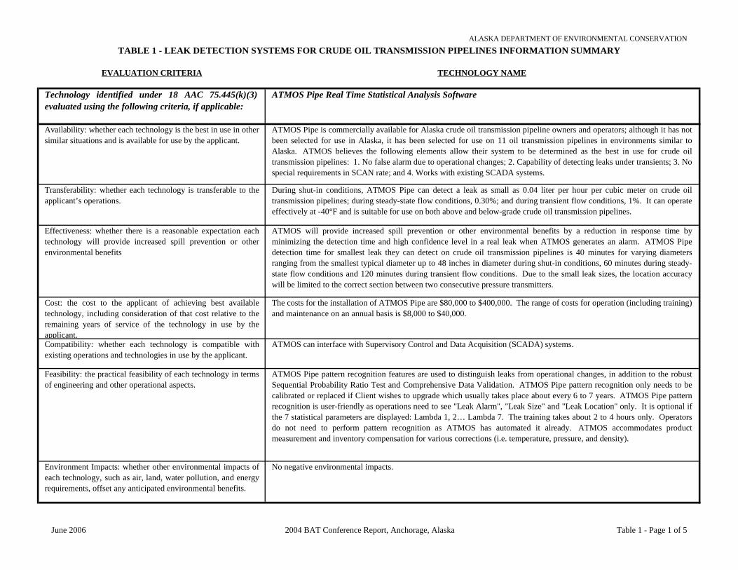
TABLE 1 - LEAK DETECTION SYSTEMS FOR CRUDE OIL TRANSMISSION PIPELINES INFORMATION SUMMARYALASKA DEPARTMENT OF ENVIRONMENTAL CONSERVATION
EVALUATION CRITERIA TECHNOLOGY NAME
Technology identified under 18 AAC 75.445(k)(3)evaluated using the following criteria, if applicable:
ATMOS Pipe Real Time Statistical Analysis Software
Availability: whether each technology is the best in use in othersimilar situations and is available for use by the applicant.
ATMOS Pipe is commercially available for Alaska crude oil transmission pipeline owners and operators; although it has notbeen selected for use in Alaska, it has been selected for use on 11 oil transmission pipelines in environments similar toAlaska. ATMOS believes the following elements allow their system to be determined as the best in use for crude oiltransmission pipelines: 1. No false alarm due to operational changes; 2. Capability of detecting leaks under transients; 3. Nospecial requirements in SCAN rate; and 4. Works with existing SCADA systems.
Transferability: whether each technology is transferable to theapplicant’s operations.
During shut-in conditions, ATMOS Pipe can detect a leak as small as 0.04 liter per hour per cubic meter on crude oiltransmission pipelines; during steady-state flow conditions, 0.30%; and during transient flow conditions, 1%. It can operateeffectively at -40°F and is suitable for use on both above and below-grade crude oil transmission pipelines.
Effectiveness: whether there is a reasonable expectation eachtechnology will provide increased spill prevention or otherenvironmental benefits
ATMOS will provide increased spill prevention or other environmental benefits by a reduction in response time byminimizing the detection time and high confidence level in a real leak when ATMOS generates an alarm. ATMOS Pipedetection time for smallest leak they can detect on crude oil transmission pipelines is 40 minutes for varying diametersranging from the smallest typical diameter up to 48 inches in diameter during shut-in conditions, 60 minutes during steady-state flow conditions and 120 minutes during transient flow conditions. Due to the small leak sizes, the location accuracywill be limited to the correct section between two consecutive pressure transmitters.
Cost: the cost to the applicant of achieving best availabletechnology, including consideration of that cost relative to theremaining years of service of the technology in use by theapplicant.
The costs for the installation of ATMOS Pipe are $80,000 to $400,000. The range of costs for operation (including training)and maintenance on an annual basis is $8,000 to $40,000.
Compatibility: whether each technology is compatible withexisting operations and technologies in use by the applicant.
ATMOS can interface with Supervisory Control and Data Acquisition (SCADA) systems.
Feasibility: the practical feasibility of each technology in termsof engineering and other operational aspects.
ATMOS Pipe pattern recognition features are used to distinguish leaks from operational changes, in addition to the robustSequential Probability Ratio Test and Comprehensive Data Validation. ATMOS Pipe pattern recognition only needs to becalibrated or replaced if Client wishes to upgrade which usually takes place about every 6 to 7 years. ATMOS Pipe patternrecognition is user-friendly as operations need to see "Leak Alarm", "Leak Size" and "Leak Location" only. It is optional ifthe 7 statistical parameters are displayed: Lambda 1, 2… Lambda 7. The training takes about 2 to 4 hours only. Operatorsdo not need to perform pattern recognition as ATMOS has automated it already. ATMOS accommodates productmeasurement and inventory compensation for various corrections (i.e. temperature, pressure, and density).
Environment Impacts: whether other environmental impacts ofeach technology, such as air, land, water pollution, and energyrequirements, offset any anticipated environmental benefits.
No negative environmental impacts.
June 2006 2004 BAT Conference Report, Anchorage, Alaska Table 1 - Page 1 of 5

TABLE 1 - LEAK DETECTION SYSTEMS FOR CRUDE OIL TRANSMISSION PIPELINES INFORMATION SUMMARYALASKA DEPARTMENT OF ENVIRONMENTAL CONSERVATION
EVALUATION CRITERIA TECHNOLOGY NAME
Technology identified under 18 AAC 75.445(k)(3)evaluated using the following criteria, if applicable:
duoThane
Availability: whether each technology is the best in use in othersimilar situations and is available for use by the applicant.
Ophir’s duoThane technology is not yet commercially available for Alaska crude oil transmission pipeline owners andoperators and has not been selected for use on crude oil transmission pipelines in Alaska or been selected for use in otherareas with environments similar to those in Alaska. Currently, there is not a system in use that specifically targets pipelineleaks under waterways. The duoThane sensor has superior sensitivity as compared to other hydrocarbon sensors such asFlame Ionization Detectors.
Transferability: whether each technology is transferable to theapplicant’s operations.
During shut-in conditions, duoThane’s detection sensitivity for ethane is 33 parts per billion (ppb) and for methane is 50ppb. This sensitivity is not dependent on shut-in, steady state or transient flow conditions. duoThane can operate effectively(including accurate product release alarming, accurate identification of leak location, and accurate identification of leak rate)at approximately -60° F, and it is suitable for use on both above and below-grade crude oil transmission pipelines.
Effectiveness: whether there is a reasonable expectation eachtechnology will provide increased spill prevention or otherenvironmental benefits
duoThane can provide increased spill prevention or other environmental benefits with its early leak detection; specificallyfor spills under waterways. The detection time for shut-in, steady-state and transient flow conditions is dependent on theproduct transport time from the pipe, through the water, and into the atmosphere. It may also be dependent on the winddirection, current speed and the surface condition of the water (i.e., broken ice). The leak location can be defined down tothe length of pipe running under the waterway.
Cost: the cost to the applicant of achieving best availabletechnology, including consideration of that cost relative to theremaining years of service of the technology in use by theapplicant.
The range of costs for the installation of duoThane on crude oil transmission pipelines with varying complexities and ofvarying diameters ranging from the smallest typical diameter up to 48 inches in diameter is $10,000 per unit when inproduction. The cost for the operation, including training, and maintenance is $2,000 per unit per year of operation.
Compatibility: whether each technology is compatible withexisting operations and technologies in use by the applicant.
duoThane can interface with Supervisory Control and Data Acquisition (SCADA) systems.
Feasibility: the practical feasibility of each technology in termsof engineering and other operational aspects.
False alarms are detected and corrected by the algorithms used in duoThane with optical spectral correlation that uniquelydetects methane and ethane, rejecting all other hydrocarbons and flammable gases. The duoThane software is selfcalibrating, very user friendly, with a programmable system set-up. Training requirements for duoThane software areminimal.
Environment Impacts: whether other environmental impacts ofeach technology, such as air, land, water pollution, and energyrequirements, offset any anticipated environmental benefits.
No negative environmental impacts.
June 2006 2004 BAT Conference Report, Anchorage, Alaska Table 1 - Page 2 of 5

TABLE 1 - LEAK DETECTION SYSTEMS FOR CRUDE OIL TRANSMISSION PIPELINES INFORMATION SUMMARYALASKA DEPARTMENT OF ENVIRONMENTAL CONSERVATION
EVALUATION CRITERIA TECHNOLOGY NAME
Technology identified under 18 AAC 75.445(k)(3)evaluated using the following criteria, if applicable:
LeakNet
Availability: whether each technology is the best in use in othersimilar situations and is available for use by the applicant.
LeakNet is commercially available and successfully installed in Alaska and around the world for over 25 years; it currentlyholds two BAT certifications from the State of Alaska, with the largest number of installed systems on the North Slope.LeakNet is monitoring many pipelines in Alaska and has been selected on over 12 sites to monitor over 20 transmissionlines. LeakNet is monitoring over 400 pipelines worldwide in terrains ranging from arctic to swamp land, desert to subseaapplications. Calculations for leak detection are not impacted by different climatic conditions.
Transferability: whether each technology is transferable to theapplicant’s operations.
LeakNet's sensitivity for shut-in conditions is dependent on line volume. Pressure-Point Analysis (PPA) can detect leaks onlosses as small as 14 ml out of 7,000 gallons, 0.1 gallon out of 116,000 gallons, and 4.5 parts per million (ppm) on largerlines. Detects existing leaks and those that have just occurred; if product can flow and be effectively measured, leakdetection with MassPack can be performed. The effect on PPA is generally negligible because due to thermal mass issues,temperature can't change much over the time it takes to detect a leak. LEAKNET is suitable for both above and below gradepipelines.
Effectiveness: whether there is a reasonable expectation eachtechnology will provide increased spill prevention or otherenvironmental benefits
LeakNet provides three methods of leak detection; during flowing conditions it uses PPA and MassPack. PPA detectsleaks on losses of about 0.7-percent of flow; MassPack responds to a leak only after the event has traveled to both ends ofthe line and the measurable difference exceeds the alarm threshold (depending on the leak size this could take minutes to anhour.) LeakNet’s leak location option, Locator, operates from the PPA module, requires 0.25-second updates in liquids, andcan tolerate slower updates in gas because the rate of change is much slower in gaseous conditions. Using internallycalculated speed of sound, Locator completes a time distance calculation that includes weighted interpolation of the resultsto generate a location with a guaranteed accuracy of no less than 600 meters.
Cost: the cost to the applicant of achieving best availabletechnology, including consideration of that cost relative to theremaining years of service of the technology in use by theapplicant.
Varies; a short pipeline might require monitoring four field instruments, referred to as points; a longer line forty or seventy-five points. LeakNet is available in standard sizes of 5 to 1,000 points. Larger size systems cost more, but point costdecreases. Systems receiving data from SCADA are less expensive than modem. All points are available immediatelywithout additional licensing fees. No additional maintenance costs, no annual fee, and 24-hour help line available.
Compatibility: whether each technology is compatible withexisting operations and technologies in use by the applicant.
LeakNet is compatible with most Supervisory Control and Data Acquisition (SCADA) systems.
Feasibility: the practical feasibility of each technology in termsof engineering and other operational aspects.
The individual points in the system provide only an “alarm/no alarm” status. SmartPoint can use any PPA point, anyMassPack accumulator, and any other configured SmartPoint to create logical relationship. Configuration of SmartPoint isdone in a point-and-click-editor window, taking only minutes. Regular and repeated calibration is not necessary; ifinstruments can “see” it, LEAKNET can detect it. LeakNet is easily understood and user-friendly; training an operator takes~8 hours; administrator training ~two days; or have facility trainer (to coach training of operators/administrators.) Trainingis provided for all options purchased by the Users.
Environment Impacts: whether other environmental impacts ofeach technology, such as air, land, water pollution, and energyrequirements, offset any anticipated environmental benefits.
No negative environmental impacts.
June 2006 2004 BAT Conference Report, Anchorage, Alaska Table 1 - Page 3 of 5

TABLE 1 - LEAK DETECTION SYSTEMS FOR CRUDE OIL TRANSMISSION PIPELINES INFORMATION SUMMARYALASKA DEPARTMENT OF ENVIRONMENTAL CONSERVATION
EVALUATION CRITERIA TECHNOLOGY NAME
Technology identified under 18 AAC 75.445(k)(3)evaluated using the following criteria, if applicable:
WaveAlert
Availability: whether each technology is the best in use in other similarsituations and is available for use by the applicant.
Acoustic System’s WaveAlert is available for Alaska crude oil transmission pipeline owners and operators; they have not been selected foruse on crude oil transmission pipelines in Alaska; but have been selected for use in 30 other areas with environments similar to those inAlaska. Acoustics believes WaveAlert technology is the most reliable (fewest false alarm), quickest and most accurate leak detection andlocation system available.
Transferability: whether each technology is transferable to theapplicant’s operations.
Leak detection on varying crude oil transmission pipelines depends on pipeline pressure and sensor spans. For shut-in conditionsWaveAlert can detect a 0.04 liter per hour per cubic feet leak; for steady-flow conditions, 0.30%; and 1% for transient flow conditions.WaveAlert has been tested down to -40C and successfully used in Russia, Siberia; and is suitable for use on both above and below-gradecrude oil transmission pipelines.
Effectiveness: whether there is a reasonable expectation eachtechnology will provide increased spill prevention or otherenvironmental benefits
WaveAlert has been used for automatic valve shut-off upon detecting leaks and is the only system with a proven record of actually detecting a leak and automatically shut-off a pipeline, preventing potential disaster, by stopping leakage within one to two minutes of leak occurring.Detection time for the smallest leak WaveAlert can detect during shut-in conditions, during steady-state flow conditions, and duringtransient flow conditions depends on the distance between sensors, but typically is less than 60 seconds. WaveAlert's detection time isindependent of leak size. Leak location accuracy depends on distance between sensors, with a typical leak location accuracy of +/- 30meters for all conditions (shut-in, steady state, and transient).
Cost: the cost to the applicant of achieving best available technology,including consideration of that cost relative to the remaining years ofservice of the technology in use by the applicant.
The cost for the installation of WaveAlert depends on the length of the pipeline and performance requirement. The typical cost ranges from$80,000 and up. Costs for operation and maintenance is very low since no calibration is required and the system comes with a one yearwarranty. Training is included in the above system cost.
Compatibility: whether each technology is compatible with existingoperations and technologies in use by the applicant.
WaveAlert can interface with Supervisory Control and Data Acquisition (SCADA) systems.
Feasibility: the practical feasibility of each technology in terms ofengineering and other operational aspects.
During installation, filters and algorithms are fine-tuned to provide an extreme low false alarm rate; typically less than one per year.WaveAlert's data processing algorithms and multilayer redundant and cross verification structure, including signature recognition methods,are based on finger-print signature data. WaveAlert detects leaks under all conditions with low false alarm rate, and is used for automaticvalve shut-off with proven record of actually detecting and locating leaks. No calibration required unless product or configuration ischanged. All variables and parameters are set during installation and commissioning. No further adjustments required. WaveAlert is easyto use and requires no interpretation of data. Training typically requires 1/2 day. No operator pattern recognition. WaveAlert providesLEAK / NO LEAK output and requires no statistical "guessing game" and NO NEED for expert operator to interpret the data. SinceWaveAlert does NOT detect a leak based on "conservation law,” it does NOT require any correction or compensation based on temperature,pressure, or density in order to detect and accurately locate the leak.
Environment Impacts: whether other environmental impacts of eachtechnology, such as air, land, water pollution, and energy requirements,offset any anticipated environmental benefits.
No negative environmental impacts.
June 2006 2004 BAT Conference Report, Anchorage, Alaska Table 1 - Page 4 of 5

TABLE 1 - LEAK DETECTION SYSTEMS FOR CRUDE OIL TRANSMISSION PIPELINES INFORMATION SUMMARYALASKA DEPARTMENT OF ENVIRONMENTAL CONSERVATION
EVALUATION CRITERIA TECHNOLOGY NAME
Technology identified under 18 AAC 75.445(k)(3)evaluated using the following criteria, if applicable:
Ultrasonic Flowmeters
Availability: whether each technology is the best in use in other similarsituations and is available for use by the applicant.
Ultrasonic Flowmeters are commercially available for Alaska crude oil transmission pipeline owners and operators, and systems areinstalled world wide on both crude and refined product lines. Ultrasonic Flowmeters have not been selected for use on crude oiltransmission pipelines in Alaska. Ultrasonic Flowmeters have only been used as a secondary device on the Alyeska pipeline. Systemprovides a contact enclosure to the Alyeska system if flow rate experiences pre-determined change. Other similar environments it has beenused on include one large system in Russia and many others in less environmentally challenging locations. Ultrasonic Flowmeters'sensitivity allows them to be visually operated with no false alarms; detection is about 0.25% of pipeline segment through put. Otherfeatures include direct measurement, sale source and package price. Ultrasonic Flowmeters work under static conditions and are notimpacted by large pressure transients or transient flow conditions.
Transferability: whether each technology is transferable to theapplicant’s operations.
During shut-in conditions, Ultrasonic Flowmeters can detect up to 0.20% when used on crude oil transmission pipelines; during steady-state flow conditions up to 0.25%, and during transient flow conditions, it is determined by the amount of volume within segment.Ultrasonic Flowmeters can operate effectively at -30°C and are suitable on both above and below-grade crude oil transmission pipelines.
Effectiveness: whether there is a reasonable expectation eachtechnology will provide increased spill prevention or otherenvironmental benefits
Ultrasonic Flowmeters will provide increased spill prevention or other environmental benefits as the system can effectively detect smallleaks within 2 to 5 minutes and catastrophic leaks in 1 minute. Detection time for the smallest leak Ultrasonic Flowmeters can detectduring shut-in conditions is 2 to 5 minutes; during steady-state flow conditions, 60 minutes; and during transient flow conditions from 2 to5 minutes. Leak location accuracy is +/- 50 meters in all cases.
Cost: the cost to the applicant of achieving best available technology,including consideration of that cost relative to the remaining years ofservice of the technology in use by the applicant.
Ultrasonic Flowmeters installation costs depend on leak sensitivity required. Ultrasonic Flowmeters software license cost would runapproximately $15,000. Topology file preparation and optimization costs are in the area of $4,500 per segment. Pipeline segments arerecommended not to exceed 40 km in length where leak detection is also required.
Compatibility: whether each technology is compatible with existingoperations and technologies in use by the applicant.
Ultrasonic Flowmeters can interface with Supervisory Control and Data Acquisition (SCADA) systems and are compatible withconventional systems.
Feasibility: the practical feasibility of each technology in terms ofengineering and other operational aspects.
Ultrasonic Flowmeters have ability to review field diagnostics to determine the "health" of a field device. If the Ultrasonic Flowmeterdetermines the health is less than optimum the Ultrasonic Flowmeter will automatically adjust itself to compensate by lowering theconfidence factor for a given segment. Ultrasonic Flowmeters rarely need to be calibrated or replaced, however, the best guess forrecalibration or replacement would be approximately 10 years. Ultrasonic Flowmeters use a mass balance with line pack consideration witha secondary temperature modeling routine used to adjust the Application Confidence factor (AppCon) based on how well the temperaturemodel fits the actual observed readings. Typically a 1 to 2 day training session is satisfactory for most operators to grasp the aspects anduse Ultrasonic Flowmeters. Operators should start with an understanding of what to expect when a leak occurs. Typically training for theoperators takes 1 day, however, a refresher course of 1/2 to 1 day is often useful after the operators have spent time working with theUltrasonic Flowmeters.
Environment Impacts: whether other environmental impacts of eachtechnology, such as air, land, water pollution, and energy requirements,offset any anticipated environmental benefits.
No negative environmental impacts.
June 2006 2004 BAT Conference Report, Anchorage, Alaska Table 1 - Page 5 of 5

TABLE 2 - SECONDARY CONTAINMENT LINERS FOR OIL STORAGE TANKS INFORMATION SUMMARYALASKA DEPARTMENT OF ENVIRONMENTAL CONSERVATION
EVALUATION CRITERIA TECHNOLOGY NAME
Technology identified under 18 AAC 75.445(k)(3)evaluated using the following criteria, if applicable:
Petrogard VI and X
Availability: whether each technology is the best in use in othersimilar situations and is available for use by the applicant.
MPC Containment’s Petrogard VI and X liners have been used in Alaska for approximately 75 projects, includingElmendorf and Eielson AFBs; in other storage tank projects, including Canada’s DEW line sites and Thule AFB, Greenland;in hot regions such as Diego Garcia and the Azores. Petrogard X liner has also been used in for military pillow tanks wherethe tanks were filled continuously with various petroleum-based fuels for 10 years.
Transferability: whether each technology is transferable to theapplicant’s operations.
Petrogard VI, a coated fabric which will withstand dead pull, and gets stiff at about 20°F. Petrogard VI and X are reportedto have a permeability for JP-8 of 5 x 10⁻⁹ centimeters per second (cm/sec) and of 9 x 10⁻¹⁰ cm/sec, respectively. PetrogardVI permeability is 9.03 x 10⁻¹⁰ cm/sec for unleaded gasoline, which meets definition found in 18 AAC 75.990(124), even fornew installations. Petrogard X’s permeability is less than Petrogard IV’s, and therefore meets the definition of “sufficientlyimpermeable” in 18 AAC 75.990(124).
Effectiveness: whether there is a reasonable expectation eachtechnology will provide increased spill prevention or otherenvironmental benefits
Petrogard VI and X liners have high physical properties, flexibility, low rate of thermal expansion, UV stable, with goodcold weather applications and ability to hold products for long periods of time. Petrogard VI and X liners meet militaryspecification requirements.
Cost: the cost to the applicant of achieving best availabletechnology, including consideration of that cost relative to theremaining years of service of the technology in use by theapplicant.
The cost per square foot for the installation of Petrogard VI liners are approximately $1.25 for material. Installation is $0.10to $1.00 per square foot depending on size and complexity. Petrogard VI is half the price of Petrogard X. Welds are madewith 2 inches flap, minimizing the extra material needed for the flap.
Compatibility: whether each technology is compatible withexisting operations and technologies in use by the applicant.
Both Petrogard VI and X liners are compatible with crude oil, diesel fuel, fuel oil, gasoline, and aviation gas in 7 dayimmersion tests.
Feasibility: the practical feasibility of each technology in termsof engineering and other operational aspects.
The weak points in Petrogard VI and X liners would be welding around penetrations, however, this can be resolved by useof proper welding and adhesion technologies.
Environment Impacts: whether other environmental impacts ofeach technology, such as air, land, water pollution, and energyrequirements, offset any anticipated environmental benefits.
No negative environmental impacts to offset environmental benefits. If a generator is used in the welding process, care mustbe taken to prevent or contain oil leaks.
June 2006 2004 BAT Conference Report, Anchorage, Alaska Table 2 - Page 1 of 2

TABLE 2 - SECONDARY CONTAINMENT LINERS FOR OIL STORAGE TANKS INFORMATION SUMMARYALASKA DEPARTMENT OF ENVIRONMENTAL CONSERVATION
EVALUATION CRITERIA TECHNOLOGY NAME
Technology identified under 18 AAC 75.445(k)(3)evaluated using the following criteria, if applicable:
GSE HDPE Liners
Availability: whether each technology is the best in use in othersimilar situations and is available for use by the applicant.
GSE High Density Polyethylene (HDPE) liners have been selected for use on over 12 oil storage tank projects in Alaska,including Prudhoe Bay.
Transferability: whether each technology is transferable to theapplicant’s operations.
If there is a spill GSE HDPE liners will swell, and if the substance is cleaned up prior to breach of permeability, the fabricwill resume original shape. Textured GSE HDPE liners will allow adherence to shotcrete. GSE HDPE liners aremanufactured from resin. Breakthrough/permeation with gasoline is about 72 hours.
Effectiveness: whether there is a reasonable expectation eachtechnology will provide increased spill prevention or otherenvironmental benefits
The lowest temperature for field welding GSE HDPE liners is 0°F (15°C). GSE HDPE liners use carbon black forprotection from ultraviolet radiation, as well as optional coatings and physical protection, i.e., burying. GSE HDPE linerscan be exposed to ultraviolet radiation without showing signs of deterioration for 30 to 70 years, depending on latitude.
Cost: the cost to the applicant of achieving best availabletechnology, including consideration of that cost relative to theremaining years of service of the technology in use by theapplicant.
The cost for GSE HDPE liners for Alaska oil storage tanks per square foot is highly variable depending on location andproject size. Installation is the expensive part. More penetrations result in more cost. Transport adds to the cost with eachroll of liner (22.5 feet wide) weighing up to 4,000 pounds plus equipment transport. Power requirements for an extrusionwelder are high and requires very good welder and installer personnel. GSE HDPE liners are best suited for large jobs as thecost of liner material will offset the high cost of equipment needed for installation.
Compatibility: whether each technology is compatible withexisting operations and technologies in use by the applicant.
GSE HDPE liners have physical properties that make it the most commonly used geomembrane in its type of application.Temperature ranges for use of GSE HDPE liners is -130°F to 302°F. GSE HDPE liner widths range from 27 to 90millimeters. Tensile strength at break ranges from 122 to 405 pounds per inch of width. Chemical resistance is limited andliner material may reflect some attack from benzene, gasoline, oils and grease, and kerosene. Chemical resistance isunsatisfactory (liner material is not resistant) for toluene and xylenes. Breakthrough/permeation with gasoline is about 72hours but crude oil had no effect on permeability. Puncture resistance ranges from 59 to 198 pounds. Tear resistance is 21to 70 pounds with 12% to 14% elongation before failure.
Feasibility: the practical feasibility of each technology in termsof engineering and other operational aspects.
GSE HDPE liners have high thermal expansion and contraction characteristics, are labor intensive, require induced wrinkles,and are best suited for large projects of more than 50,000 square feet. Design considerations include low-permeability andchemical resistance to gasoline; repairs requiring skilled welders; size of the welder and generator; wrinkles to compensatefor high rate of thermal contraction and expansion; mechanical connections to tanks, piping, supports, etc. These designconsiderations can be resolved by determining how much extra liner would be needed due to thermal expansion andcontraction and leaving wrinkles. Wrinkles placed on purpose should not fall over on themselves and should be evenlyspaced. Foundations or subgrade required for GSE HDPE liners include geotech fabric below liner or pure sand to protectthe GSE HDPE liner from punctures. GSE HDPE liners may require geoweb reinforcement. Best to have preparedsubgrade underneath the liner that is void of sharp rocks.
Environment Impacts: whether other environmental impacts ofeach technology, such as air, land, water pollution, and energyrequirements, offset any anticipated environmental benefits.
GSE HDPE liners utilize petroleum by-products, have long viability, and do not break down into harmful chemicals into theenvironment. Potential oil leaks from the generator during installation and repairs. Permeability and chemical resistancemay slow a release, but may still allow the release to enter the environment.
June 2006 2004 BAT Conference Report, Anchorage, Alaska Table 2 - Page 2 of 2

TABLE 3 - FAST WATER BOOMING INFORMATION SUMMARYALASKA DEPARTMENT OF ENVIRONMENTAL CONSERVATION
EVALUATION CRITERIA TECHNOLOGY NAME
Technology identified under 18 AAC 75.445(k)(3)evaluated using the following criteria, if applicable:
NOFI Current Buster
Availability: whether each technology is the best in use in othersimilar situations and is available for use by the applicant.
The NOFI Current Buster (NCB) (for coastal, inlets, harbors and rivers) and Ocean Buster (for high seas offshore, coasts,and sounds) are on the market and being used in Alaska by plan holders (i.e., SERVS and CISPRI). The NCB was selectedfor use on the Prince William Sound during the “Windy Bay” spill; in Fast Waters (Vatlestraumen, Norway) during the“Rocknes” heavy fuel oil incident in January 2004; and tested with Fina Green oil in 5 knots towing speed by the DutchCoast Guard in Holland.
Transferability: whether each technology is transferable to theapplicant’s operations.
To benefit from the NCB’s separator capacity, the depth in a stream should be at least 8 feet. The NCB will be effective in acurrent up to 4 knots or greater. The NCB can be used in the ocean with rip currents greater than or equal to 3 knots as longas the rip currents in the ocean do not mix the oil into the water column before approaching with the system. The NCB canalso be implemented in a river/stream with a current of greater than or equal to 3 knots in the presence of occasional icefloes/pans, however, it also depends on the “environmental conditions” i.e., regularity and size ice floes that appear.Mechanically the NCB system is very strong and should handle the ice well.
Effectiveness: whether there is a reasonable expectation eachtechnology will provide increased spill prevention or otherenvironmental benefits
The NCB system has been tested with a wide range of oils. The results showed no significant differences in effectiveness.The NCB was used during the “Rocknes” heavy fuel incident in Fast Waters with tidal currents running from 2 to 4 knots.
Cost: the cost to the applicant of achieving best availabletechnology, including consideration of that cost relative to theremaining years of service of the technology in use by theapplicant.
The cost of a NCB is approximately $110,000 (without operating equipment which may range from a tailor made woodenpallet to a 10 foot container with a built in boom reel and power pack).
Compatibility: whether each technology is compatible withexisting operations and technologies in use by the applicant.
A strategic and or tactical plan will benefit the performance of the system but a Standard Operations Procedure coveringdifferent geographical scenarios and spill situations will also be very effective. To operate the NCB at sea normally requirestwo smaller boats, while on a river the system just can be anchored. It is also possible to tow the NCB behind an outrigger,making the operation a single ship, side weep. At a minimum, two persons may deploy the NCB but additional hands willspeed up the process and make it safer. When towboats are used the minimum required is the towboat crew. Anchored in ariver with a smaller spill (than the storage capacity) NCB may work unattended.
Feasibility: the practical feasibility of each technology in termsof engineering and other operational aspects.
The NCB can be used based on the information supplied in operator manuals; however it is a great advantage if personnelhave trained with the system before an oil spill. The response time will be largely dependent on the quality and scramblingtime of the response team, equipment immediately available (trucks, helicopters or shallow draft boats, etc.) and, if thesystem has been preloaded, on the means of transport and to what degree this particular spill situation has been planned andtrained for. The time will vary between driving/flying time + 20 minutes deployment and installation time up to noimmediate response at all (area inaccessible by air due to fog, no access by the river because of waterfalls and similaradverse conditions).
Environment Impacts: whether other environmental impacts ofeach technology, such as air, land, water pollution, and energyrequirements, offset any anticipated environmental benefits.
There are no negative environmental impacts. By effectively containing and controlling the oil before reaching the shores orby stopping the oil from exposing the river systems downstream of the spill site the Current Buster will present a significantreduction of the negative consequences of an oil spill both on land, in streams and rivers or in the seas.
June 2006 2004 BAT Conference Report, Anchorage, Alaska Table 3 - Page 1 of 4

TABLE 3 - FAST WATER BOOMING INFORMATION SUMMARYALASKA DEPARTMENT OF ENVIRONMENTAL CONSERVATION
EVALUATION CRITERIA TECHNOLOGY NAME
Technology identified under 18 AAC 75.445(k)(3)evaluated using the following criteria, if applicable:
Boom Vane
Availability: whether each technology is the best in use in othersimilar situations and is available for use by the applicant.
The Boom Vane is available to contingency plan holders in Alaska and has been selected for use on approximately 5 Alaskafast navigable water operations including shore-based (streams, rivers, estuaries, and tidal areas) and in vessel-based sweepmodes, to date. A total of 104 Boom Vane units have been sold outside Alaska.
Transferability: whether each technology is transferable to theapplicant’s operations.
The Boom Vane technology can be implemented in streams with currents greater than or equal to 3 knots; and in the oceanwith rip currents of greater than or equal to 3 knots. It can also be implemented in a river/stream with a current of greaterthan or equal to 3 knots in the presence of occasional ice floes/pans. The Boom Vane technology can be implemented as avessel sweep application in an off shore environment with a current of greater than or equal to 3 knots.
Effectiveness: whether there is a reasonable expectation eachtechnology will provide increased spill prevention or otherenvironmental benefits
The Boom Vane performs well from 0.5 to 5 or 6 knots. Specific examples of the Boom Vane’s effectiveness would be thenumerous official demonstrations where it was launched in less than half an hour, by two men with no boats or anchors.Environmental benefits include timely spill responses and improved booming.
Cost: the cost to the applicant of achieving best availabletechnology, including consideration of that cost relative to theremaining years of service of the technology in use by theapplicant.
The cost for the purchase of the Boom Vane for containment and recovery of oil in Alaska is about $11,000. A two-daytraining session is required to operate and maintain the Boom Vane. Operator manuals are included in the cost for the BoomVane.
Compatibility: whether each technology is compatible withexisting operations and technologies in use by the applicant.
Use of the Boom Vane does not require a strategic deployment strategy, but knowledge of the response site shortens thedeployment time even further. No boats are needed to deploy the Boom Vane. The Boom Vane takes a minimum of twopeople to deploy, ideally three, and does not require continuous personnel support. After its initial deployment, one personis required to operate the Boom Vane system.
Feasibility: the practical feasibility of each technology in termsof engineering and other operational aspects.
The Boom Vane can be effectively utilized by responders based on the information supplied in operator manuals alone,given they have an understanding of moving waters. Minimum time needed to deploy the Boom Vane is 30 minutes, if youhave trained staff with knowledge of the deployment site. If deployed to a stream that is accessible by road and less than 10miles away, the Boom Vane could be deployed in less than one hour. If the deployment site is a stream with width varyingfrom 30 to 80 feet, and is not road accessible, but located 10 miles away, the Boom Vane could be hand carried. Thedeployment time is then dependent on terrain and distance.
Environment Impacts: whether other environmental impacts ofeach technology, such as air, land, water pollution, and energyrequirements, offset any anticipated environmental benefits.
The Boom Vane would have no negative environmental impacts.
June 2006 2004 BAT Conference Report, Anchorage, Alaska Table 3 - Page 2 of 4
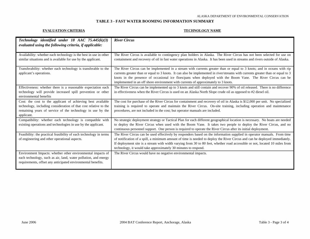
TABLE 3 - FAST WATER BOOMING INFORMATION SUMMARYALASKA DEPARTMENT OF ENVIRONMENTAL CONSERVATION
EVALUATION CRITERIA TECHNOLOGY NAME
Technology identified under 18 AAC 75.445(k)(3)evaluated using the following criteria, if applicable:
River Circus
Availability: whether each technology is the best in use in othersimilar situations and is available for use by the applicant.
The River Circus is available to contingency plan holders in Alaska. The River Circus has not been selected for use oncontainment and recovery of oil in fast water operations in Alaska. It has been used in streams and rivers outside of Alaska.
Transferability: whether each technology is transferable to theapplicant’s operations.
The River Circus can be implemented in a stream with currents greater than or equal to 3 knots; and in oceans with ripcurrents greater than or equal to 3 knots. It can also be implemented in river/streams with currents greater than or equal to 3knots in the presence of occasional ice floes/pans when deployed with the Boom Vane. The River Circus can beimplemented in an off shore environment with currents of approximately to 3 knots.
Effectiveness: whether there is a reasonable expectation eachtechnology will provide increased spill prevention or otherenvironmental benefits
The River Circus can be implemented up to 3 knots and still contain and recover 90% of oil released. There is no differencein effectiveness when the River Circus is used on an Alaska North Slope crude oil as opposed to #2 diesel oil.
Cost: the cost to the applicant of achieving best availabletechnology, including consideration of that cost relative to theremaining years of service of the technology in use by theapplicant.
The cost for purchase of the River Circus for containment and recovery of oil in Alaska is $12,000 per unit. No specializedtraining is required to operate and maintain the River Circus. On-site training, including operation and maintenanceprocedures, are not included in the cost; but operator manuals are included.
Compatibility: whether each technology is compatible withexisting operations and technologies in use by the applicant.
No strategic deployment strategy or Tactical Plan for each different geographical location is necessary. No boats are neededto deploy the River Circus when used with the Boom Vane. It takes two people to deploy the River Circus, and nocontinuous personnel support. One person is required to operate the River Circus after its initial deployment.
Feasibility: the practical feasibility of each technology in termsof engineering and other operational aspects.
The River Circus can be used effectively by responders based on the information supplied in operator manuals. From timeof notification of a spill, a minimum amount of time is needed to deploy the River Circus and can be deployed immediately.If deployment site is a stream with width varying from 30 to 80 feet, whether road accessible or not, located 10 miles fromtechnology, it would take approximately 30 minutes to respond.
Environment Impacts: whether other environmental impacts ofeach technology, such as air, land, water pollution, and energyrequirements, offset any anticipated environmental benefits.
The River Circus would have no negative environmental impacts.
June 2006 2004 BAT Conference Report, Anchorage, Alaska Table 3 - Page 3 of 4

TABLE 3 - FAST WATER BOOMING INFORMATION SUMMARYALASKA DEPARTMENT OF ENVIRONMENTAL CONSERVATION
EVALUATION CRITERIA TECHNOLOGY NAME
Technology identified under 18 AAC 75.445(k)(3)evaluated using the following criteria, if applicable:
Water Structures
Availability: whether each technology is the best in use in other similarsituations and is available for use by the applicant.
Water Structures are available to contingency plan holders in Alaska. Areas other than Alaska where the Water Structurehas been used include Chevron, California.
Transferability: whether each technology is transferable to theapplicant’s operations.
The Water Structure can be implemented in a stream with currents greater than or equal to 3 knots; but it is not suitable inthe ocean with rip currents greater than or equal to 3 knots. The Water Structure can be implemented in a river/stream witha current greater than or equal to 3 knots in the presence of occasional ice floes/pans and in an offshore environment as aplatform for staging area.
Effectiveness: whether there is a reasonable expectation eachtechnology will provide increased spill prevention or otherenvironmental benefits
The Water Structure can be used to contain 100% of oil released at any velocity of water deflected from impacted area.There are no differences in effectiveness when the Water Structure is used on different oil. Environmental benefits to usingthe Water Structure include low impact and utilization of onsite materials such as water or oil to inflate the Water Structure.
Cost: the cost to the applicant of achieving best available technology,including consideration of that cost relative to the remaining years ofservice of the technology in use by the applicant.
The cost for the Water Structure for containment and recovery of oil in Alaska is $6.25 per lineal foot to $295 per linealfoot, dependent upon the height of the structure. On-site specialized training is required to operate and maintain the WaterStructure. On-site specialized training is not included with purchase of the system but operator manuals are included in thecost.
Compatibility: whether each technology is compatible with existingoperations and technologies in use by the applicant.
The Water Structure requires a strategic deployment strategy or Tactical Plan for each different geographic location it is tobe deployed. No boats are required, however, 1 to 5 people are needed to deploy the Water Structure. The Water Structuredoes not require continuous personnel support, but, does require one person after its initial deployment to operate thesystem.
Feasibility: the practical feasibility of each technology in terms ofengineering and other operational aspects.
The Water Structure cannot be used effectively by responders based on the information supplied in the operator manualsalone as not all scenarios have been updated. Water is pumped into the Water Structure for deployment and containment ofa spill in fast water. Recovered oil can also be pumped into a Water Structure used as portable storage tank. In a U.S. ArmyCorps of Engineers study, 1.5 hours was required from setup to finish for a 3 feet x 100 feet Water Structure. If the site isnot accessible by road, it could take minutes to respond using a helicopter. The size of the Water Structure will determinetime required for deployment.
Environment Impacts: whether other environmental impacts of eachtechnology, such as air, land, water pollution, and energy requirements,offset any anticipated environmental benefits.
No negative environmental impacts would be caused by the Water Structure.
June 2006 2004 BAT Conference Report, Anchorage, Alaska Table 3 - Page 4 of 4

TABLE 4 - VISCOUS OIL PUMPING SYSTEMS INFORMATION SUMMARYALASKA DEPARTMENT OF ENVIRONMENTAL CONSERVATION
EVALUATION CRITERIA TECHNOLOGY NAME
Technology identified under 18 AAC 75.445(k)(3)evaluated using the following criteria, if applicable:
Foilex Pumps
Availability: whether each technology is the best in use in othersimilar situations and is available for use by the applicant.
Foilex Twin Disc Screw (TDS) Pumps are available for shipment to Alaska and are currently being used in Alaska byChadux, SEAPRO, and SERVS. No problems with the Foilex Pumps have been noted. Once on site, the Foilex Pumpsystem takes 30 minutes with a trained operator to put into operation. Components of the systems include the pump,hydraulic power pack and hose. Foilex Pumps have been used in Russia, Norway, and Sweden during spring and summerconditions (30 to 40°F). The limiting factor for Foilex Pump system is the hose and hose couplings.
Transferability: whether each technology is transferable to theapplicant’s operations.
Foilex Pumps use injection ports to add water or steam to reduce the friction and allow more viscous oils to be pumped.The injection ports can be placed for water on the inlet side of the pump. Steam or water for injection can be placed on thedischarge side of the pump. Foilex Pumps are Positive Displacement Archimedes Screw (PDAS) pumps that operate at alow RPM; this combination creates minimal increase in emulsification. Few moving parts to Foilex Pump systems: bladesand discs are in stock and can be delivered to most sites in Alaska within 24 hours. Other than structural damage to thepump housing or screw, repairs can usually be performed in the field.
Effectiveness: whether there is a reasonable expectation eachtechnology will provide increased spill prevention or otherenvironmental benefits
The Foilex pump technology has not been tested by the U.S. Coast Guard and the Canadian Coast Guard JVOPS but, thepump was tested in March 2003 at the viscous oil workshop at the Center for Marine and Environmental Safety in Horton,Norway. Under test conditions, the pump using steam injection was able to move bitumen with a viscosity of 2 millioncentistokes. Steam pumped through the water collar actually warmed the oil and reduced the actual viscosity of the bitumento 1.3 million centistokes.
Cost: the cost to the applicant of achieving best availabletechnology, including consideration of that cost relative to theremaining years of service of the technology in use by theapplicant.
Depending on the Foilex Pump chosen, the base pump ranges from $9,000 to $18,000 without the float frame.
Compatibility: whether each technology is compatible withexisting operations and technologies in use by the applicant.
Foilex Pump systems will work with any PDAS pump in a daisy change configuration. The pumping system is compatiblewith other commonly used components, such as hydraulic power packs and hose connections, currently used in Alaska,provided the power packs can supply the adequate RPMs and the hoses are of equal size. Foilex Pump system can berepaired with common tools, unless the pump housing is cracked or the screw is broken.
Feasibility: the practical feasibility of each technology in termsof engineering and other operational aspects.
The Foilex Pump weak point may be the polyurethane coated steel discs. Having two discs increases number of parts thatcan break. A limiting factor is getting the oil to the pump. The 360° exposure of the screw can help the encounter rate withthe oil.
Environment Impacts: whether other environmental impacts ofeach technology, such as air, land, water pollution, and energyrequirements, offset any anticipated environmental benefits.
Environmental impacts from Foilex Pumps on air, land, and water are minimal, provided ample containment exists under thepump to collect potential release of hydraulic oil. The power packs to run the pumps will create some air pollution but notsignificant compared to the overall benefit. The benefits to water and land include lower risk of contamination if a vesselcan be successfully offloaded before sinking and would be significant.
June 2006 2004 BAT Conference Report, Anchorage, Alaska Table 4 - Page 1 of 3

TABLE 4 - VISCOUS OIL PUMPING SYSTEMS INFORMATION SUMMARYALASKA DEPARTMENT OF ENVIRONMENTAL CONSERVATION
EVALUATION CRITERIA TECHNOLOGY NAME
Technology identified under 18 AAC 75.445(k)(3)evaluated using the following criteria, if applicable:
GT-A Pumps
Availability: whether each technology is the best in use in othersimilar situations and is available for use by the applicant.
Lamor GT-A Positive Displacement Archimedes Screw (PDAS) Pumps are available to Alaska C-Plan holders and arecurrently used in Alaska by SERVS. Approximately 20 minutes using trained operators is required to put a GT-A Pump intooperation and begin pumping once the system is on site. GT-A Pump system components include the pump, hydraulicpower pack, and hoses. GT-A Pumps have not been used in a real event in an Arctic or Sub-Arctic environment.
Transferability: whether each technology is transferable to theapplicant’s operations.
Steam injection at the intake or water injection at the intake and outflow of the GT-A Pump can be used to reduce friction.GT-A Pumps do not lower the shear point during pumping. Anticipated emulsification effect of this system is minimal dueto type of pump, a PDAS, that has a low rpm. Most needed repairs are straight forward and do not require specialized tools.Rebuild kits are included with the system.
Effectiveness: whether there is a reasonable expectation eachtechnology will provide increased spill prevention or otherenvironmental benefits
GT-A Pump technology has been tested by the U.S. Coast Guard and the Canadian Coast Guard JVOPS committee for usein viscous oil pumping. In another test, the GT-A-50 with annular water injection was visually tested under direction offlemingCo on bitumen (3 million centistokes) with good visual results.
Cost: the cost to the applicant of achieving best availabletechnology, including consideration of that cost relative to theremaining years of service of the technology in use by theapplicant.
Costs for the installation, maintenance, and repair of the GT-A Pump vary from $9,000 for the small pump to $17,000 forthe largest pump. These costs do not include hoses, power pack, water pump for injection or steam system.
Compatibility: whether each technology is compatible withexisting operations and technologies in use by the applicant.
GT-A Pumps interface with existing VOPS currently used in Alaska, as they use standard fittings. GT-A Pump systems arecompatible with other commonly used components such as power packs and hose connections currently used in Alaska.Non-Lamor hydraulic power packs can also be used. GT-A Pumps can be repaired with common tools and it comes with arebuild kit.
Feasibility: the practical feasibility of each technology in termsof engineering and other operational aspects.
The limiting factor in the GT-A Pumps would be that hoses may become over pressurized and burst. The weight of the largepump may also be a limitation. The GT-A 115 weighs 161 lbs. These weak points can be resolved with goodcommunication between operators to keep from over pressurizing the hose and using high pressure hose and couplings.
Environment Impacts: whether other environmental impacts ofeach technology, such as air, land, water pollution, and energyrequirements, offset any anticipated environmental benefits.
Environmental impacts on air, land, and water from the GT-A Pumps are minimal, provided ample containment exists underthe pump to collect potential release of hydraulic oil. The power packs to run pumps will create some air pollution but notsignificant compared to the overall benefit.
June 2006 2004 BAT Conference Report, Anchorage, Alaska Table 4 - Page 2 of 3

TABLE 4 - VISCOUS OIL PUMPING SYSTEMS INFORMATION SUMMARYALASKA DEPARTMENT OF ENVIRONMENTAL CONSERVATION
EVALUATION CRITERIA TECHNOLOGY NAME
Technology identified under 18 AAC 75.445(k)(3)evaluated using the following criteria, if applicable:
Annular Water Injection
Availability: whether each technology is the best in use in othersimilar situations and is available for use by the applicant.
The flemingCo Annular Water Injection (AWI) technology is available and is currently being used in Alaska at Clean Seas,SERVS, SEAPRO, Chadux, Alyeska, and CISPRI. HydeMarine has provided hundreds of DESMI Positive DisplacementArchimedes Screw (PDAS) pumps to responders in Alaska. PDAS pumps are heavy oil pumps but like any mechanicalequipment, they have limitations. The flemingCo AWI technology and techniques may increase the operational limits,which is critical in Alaska, where extreme cold, harsh environments and remote locations complicate the response.
Transferability: whether each technology is transferable to theapplicant’s operations.
AWI techniques for steam or hot water injection is an option to bulk heating and is a more portable and compact solution.Steam injection with AWI technology heats up the pump intake, and gradually the entire pump, thus heating up the oil nearthe pump and creating almost similar conditions as for local bulk heating. AWI techniques enable the PDAS pumps totransfer even the most extreme viscosity oils and emulsions at operational pumping rates over operational distances. ThePDAS pumps will, in principle for each revolution, cut a segment of “thread” out of the pumped product and push it throughthe pump. There would still be stripes after pumping with no mixing and no emulsification.
Effectiveness: whether there is a reasonable expectation eachtechnology will provide increased spill prevention or otherenvironmental benefits
The AWI technology is available for use in cold conditions when oil is below pour point and will allow any PDAS pump totransfer higher viscosity oils than ever before possible. U.S. Coast Guard and the Canadian Coast Guard JVOPS test resultsdocumented the performance of flemingCo inlet flange on a DOP-250 pump and on the performance of the AWI technologyin VOPS tests and workshops during the past 5 years. The most important discharge side water lubrication test result hasbeen a impressive factor of 10 to 12 times reduction in pressure drop, while pumping oils over long distances at viscositiesnot exceeding 50,000 centistokes with a DOP-250 PDAS pump.
Cost: the cost to the applicant of achieving best availabletechnology, including consideration of that cost relative to theremaining years of service of the technology in use by theapplicant.
Budget pricing for a 6-inch pump for the inlet-side flemingCo AWI flange is $2,500. The discharge side flange is a bit less.Hydraulic power packs are extra.
Compatibility: whether each technology is compatible withexisting operations and technologies in use by the applicant.
The AWI technology is fully compatible with existing inventory of power packs and hoses. Operation of the lubricatingwater pump for the AWI system during oil transfer operations adds some complexity to the overall operation but the benefitsfar outweigh the costs.
Feasibility: the practical feasibility of each technology in termsof engineering and other operational aspects.
AWI technology is currently being used in Alaska. AWI used in conjunction with the Foilex or GT-A Pump systems onextreme viscosity oil, like bitumen or very cold heavy oil, could enhance flows.
Environment Impacts: whether other environmental impacts ofeach technology, such as air, land, water pollution, and energyrequirements, offset any anticipated environmental benefits.
The power packs to run pumps will create some air pollution but not significant compared to the overall benefit. Obviousbenefits to water and land will be lower risk of contamination is a vessel can be successfully offloaded before sinking.
June 2006 2004 BAT Conference Report, Anchorage, Alaska Table 4 - Page 3 of 3

TABLE 5 - WELL CAPPING INFORMATION SUMMARYALASKA DEPARTMENT OF ENVIRONMENTAL CONSERVATION
EVALUATION CRITERIA TECHNOLOGY NAME
Technology identified under 18 AAC 75.445(k)(3)evaluated using the following criteria, if applicable:
Abrasive Jet Cutter
Availability: whether each technology is the best in use in othersimilar situations and is available for use by the applicant.
Upon notice to proceed, assuming an Athey wagon and a D-8 dozer are at the well site, two days would be needed to initiateuse of the Abrasive Jet Cutter technology at the wellhead.
Transferability: whether each technology is transferable to theapplicant’s operations.
The Abrasive Jet Cutter can be implemented on well capping operations in Arctic conditions. Approximately 500 barrels or21,000 gallons of water (available from a heated frac tank) is required to implement the Abrasive Jet Cutter. The AbrasiveJet Cutter technology can be implemented at blowouts at an offshore platform, on a Mobile Offshore Drilling Unit, onshoreor on ice islands. The Abrasive Jet Cutter can be successfully implemented on well capping operations for an ignited wellsince it is designed to cut wells that are on fire. Transport of the Abrasive Jet Cutter from Duncan, Oklahoma, to Alaska (viaair) must be considered as a logistical requirement. There may be additional logistical requirements for transport to remoteareas.
Effectiveness: whether there is a reasonable expectation eachtechnology will provide increased spill prevention or otherenvironmental benefits.
The Abrasive Jet Cutter will provide increased spill control and reduced spill volume as it allows a wellhead to be cut whilethe well is on fire, reducing the amount of time required to control the source because the fire does not have to beextinguished.
Cost: the cost to the applicant of achieving best availabletechnology, including consideration of that cost relative to theremaining years of service of the technology in use by theapplicant.
The cost for use of the Abrasive Jet Cutter to remove a damaged wellhead and install a well capping stack or other wellcontrol technologies would be approximately $30,000 per day. This does not include the hydraulic power pack needed topower the unit or other logistical support resources.
Compatibility: whether each technology is compatible withexisting operations and technologies in use by the applicant.
The power supply required for the Abrasive Jet Cutter is a self-contained power pack hydraulic unit. Safety polices arealready in place on the North Slope to reconcile using the Abrasive Jet Cutter technology with those of the facilityoperator's. Additional resources needed for removal of the damaged wellhead and installation of the well capping stack orother well control technologies include 20-40 Frac sand, an Athey Wagon, and D-8 bulldozer. Sand is available in Alaska atHalliburton. No modifications to existing operations or equipment would be required in order to implement the Abrasive JetCutter. The resources required of the facility operator in order to use the Abrasive Jet Cutter technology include supportequipment and transportation to site. Heat-shielding and protection for the Abrasive Jet Cutter and personnel using theAbrasive Jet Cutter would be provided by Fire sleeve or Siltemp thermal sheeting material.
Feasibility: the practical feasibility of each technology in termsof engineering and other operational aspects.
The Abrasive Jet Cutter has been used on over 250 well control operations and selected for use in the pre-planning stage onover 400 projects annually. The Abrasive Jet Cutter is limited in that it is not designed to cut under water. On-goingspecialized training is required to use the Abrasive Jet Cutter as each well capping site is different. Trained personnel to usethe Abrasive Jet Cutter are provided by Halliburton.
Environment Impacts: whether other environmental impacts ofeach technology, such as air, land, water pollution, and energyrequirements, offset any anticipated environmental benefits.
No negative environmental impacts.
June 2006 2004 BAT Conference Report, Anchorage, Alaska Table 5 - Page 1 of 2

TABLE 5 - WELL CAPPING INFORMATION SUMMARYALASKA DEPARTMENT OF ENVIRONMENTAL CONSERVATION
EVALUATION CRITERIA TECHNOLOGY NAME
Technology identified under 18 AAC 75.445(k)(3)evaluated using the following criteria, if applicable:
Voluntary Blowout Ignition and Capping While Burning
Availability: whether each technology is the best in use in othersimilar situations and is available for use by the applicant.
After debris is cleared from around the blowout well, one or two days for set up is "normal" to initiate the VoluntaryBlowout Ignition and Capping While Burning technology. This is assuming that an Athey wagon and a D-8 dozer are at thewell site.
Transferability: whether each technology is transferable to theapplicant’s operations.
There is no ambient low temperature limit, as long as it is safe for personnel to work outside. If the well is on fire, severalthousand barrels of water (to keep personnel cool) would be required. In Arctic conditions, heat-shielding tin would beused. Normal water sources available on the North Slope would be used in an on-shore event; ocean water would be used ifoffshore. Voluntary Blowout Ignition and Capping While Burning can be implemented at blowouts on: an offshore platformor on a Mobile Offshore Drilling Unit with use of support marine vessels such as work boats or barges; onshore operations;and ice islands. A support and logistical requirement necessary to get the Voluntary Blowout Ignition and Capping WhileBurning technology on site would be getting a capping stack or other well control technologies, such as snubbing tools.Normally, a capping stack is brought in from Houston, if not locally available, by commercial or charter aircraft or by truckor commercial barge, if time allows.
Effectiveness: whether there is a reasonable expectation eachtechnology will provide increased spill prevention or otherenvironmental benefits
Voluntary Blowout Ignition and Capping While Burning is Boots & Coots’ preferred method for capping a blowout. Theunignited hydrocarbons from a blowout are significantly reduced as is the reduction of environmental impact.
Cost: the cost to the applicant of achieving best availabletechnology, including consideration of that cost relative to theremaining years of service of the technology in use by theapplicant.
The cost of Voluntary Blowout Ignition and Capping While Burning includes the capping stack rental, chokes, flow lines,and personnel. The costs will differ greatly from job to job, and are influenced by many variables. The cost of VoluntaryBlowout Ignition and Capping While Burning is small compared to the total blowout costs.
Compatibility: whether each technology is compatible withexisting operations and technologies in use by the applicant.
Normally, an Athey Wagon, a D-8 Cat with a winch, normal fire pumps, if not in winter arctic conditions, heat shieldingmaterial, and trained personnel are the only requirements for removal of the damaged wellhead and installation of the wellcapping stack. Due to the dangerous nature of Boots & Coots’ work in the hot zone, a unique safety policy is published,furnished and discussed with the operator. Logistical requirements for additional resources include a landing strip forcommercial or charter aircraft, and truck or helicopter transport to the blowout location. It may be necessary to removesome components of existing drilling or production facilities in order to get to the wellhead, but this is normally a part of thejob. Corrugated tin, fabricated on location, provides heat-shielding and protection for equipment and personnel using thistechnology.
Feasibility: the practical feasibility of each technology in termsof engineering and other operational aspects.
Voluntary Blowout Ignition and Capping While Burning has been used successfully since the 1950's. Historically most(90%) blowouts involve drilling operations. Limitations include having access to the wellhead, which is difficult in subseaand especially normal deep water applications. Boots & Coots Senior Well Control Specialists have over 200 years ofcombined experience. It would take 5 to 10 years depending on the individual to train personnel to use this technology.Personnel are provided by Boots & Coots.
Environment Impacts: whether other environmental impacts ofeach technology, such as air, land, water pollution, and energyrequirements, offset any anticipated environmental benefits.
While a negative impact to air is possible, utilizing these techniques to successfully cap a well involved in a sustainedblowout will result in a reduced impact to land and water due to the smaller spill volume.
June 2006 2004 BAT Conference Report, Anchorage, Alaska Table 5 - Page 2 of 2

TABLE 6 - SOURCE CONTROL TECHNOLOGY INFORMATION SUMMARYALASKA DEPARTMENT OF ENVIRONMENTAL CONSERVATION
EVALUATION CRITERIA TECHNOLOGY NAME
Technology identified under 18 AAC 75.445(k)(3)evaluated using the following criteria, if applicable:
PLIDCO Pipeline Clamps
Availability: whether each technology is the best in use in othersimilar situations and is available for use by the applicant.
Following repair of a pipeline with a PLIDCO Pipeline Clamp, it would take 7 to 10 days to produce an identical device andhave it ready for shipment to Alaska; longer for larger fittings. PLIDCO Pipeline Clamps are currently used worldwide andare commercially available to Alaska plan holders. The PLIDCO Smith+Sleeve Clamp has been used on the Alyeska TAPS48” pipeline. PLIDCO Pipeline Clamps have been selected for use on pipelines throughout the world for over 50 years.
Transferability: whether each technology is transferable to theapplicant’s operations.
PLIDCO Pipeline Clamps, up to 60 inches in diameter, have been selected for use. PLIDCO Pipeline Clamps are notdesigned to control guillotine pipeline breaks, although the PLIDCO Shear+Plug Clamp can be used to shear and plug asection of pipe for repair work. The maximum pressure a pipeline can be under and can still be sealed using a PLIDCOPipeline Clamp is 10,000 psi. The coldest temperature at which PLIDCO Pipeline Clamps can be implemented on apipeline depends on the pipeline coatings, gaskets and sealing factors.
Effectiveness: whether there is a reasonable expectation eachtechnology will provide increased spill prevention or otherenvironmental benefits.
The time required for implementation once the PLIDCO Pipeline Clamp arrives on site is highly variable, and depends onthe size of the pipeline, operating conditions, such as hazardous atmosphere, temperature, pressure, etc. It is appropriate foruse as a temporary repair technology on above ground and below ground pipes and some PLIDCO Pipeline Clamps can bewelded into place and serve as permanent repairs. There is a wide range of PLIDCO Pipeline Clamps offered that can servedifferent purposes as needed. It is not a prevention technology as much as a source control and/or repair tool. However,PLIDCO Pipeline Clamp sleeves can be installed to reinforce weakened sections of pipeline, thereby acting as a spillprevention technology. Seal shelf life for a PLIDCO Pipeline Clamp can range from 2 to 20 years if properly stored andinstalled.
Cost: the cost to the applicant of achieving best availabletechnology, including consideration of that cost relative to theremaining years of service of the technology in use by theapplicant.
The costs for various diameters and pressure ratings of PLIDCO Pipeline Clamps are highly variable. The pipeline operatormust check with PLIDCO for specific clamp needs.
Compatibility: whether each technology is compatible withexisting operations and technologies in use by the applicant.
PLIDCO Pipeline Clamps do not require specialized unique equipment or specialized training to install, but do requireheavy equipment commonly available in the oil patch. No modifications to existing operations or equipment would berequired in order to install a PLIDCO Pipeline Clamp on a pipeline in Alaska. PLIDCO Pipeline Clamps are transportableby road and air, subject to availability of suitable aircraft. PLIDCO Pipeline Clamps are also transportable by boat, subjectto availability of suitable watercraft, navigable waters, etc. PLIDCO has factory representatives available for consultation,but do not install their own clamps.
Feasibility: the practical feasibility of each technology in termsof engineering and other operational aspects.
The amount of trained response personnel required to effectively install a PLIDCO Pipeline Clamp is highly variable anddepends on the pipeline size, nature of rupture, etc. Logistical limitations for implementation of a PLIDCO Pipeline Clampinclude remote pipeline locations that could impact time to transport clamp to repair site and time to transport requiredinstallation equipment.
Environment Impacts: whether other environmental impacts ofeach technology, such as air, land, water pollution, and energyrequirements, offset any anticipated environmental benefits.
No negative environmental impacts. The pipeline and nature of the leak define the risk involved. PLIDCO Pipeline Clampsdo not introduce additional risks. Potential for damage to sensitive land areas (tundra) if heavy equipment needed forinstallation must transit off right-of-way pad.
June 2006 2004 BAT Conference Report, Anchorage, Alaska Table 6 - Page 1 of 4

TABLE 6 - SOURCE CONTROL TECHNOLOGY INFORMATION SUMMARYALASKA DEPARTMENT OF ENVIRONMENTAL CONSERVATION
EVALUATION CRITERIA TECHNOLOGY NAME
Technology identified under 18 AAC 75.445(k)(3)evaluated using the following criteria, if applicable:
Well Control Management
Availability: whether each technology is the best in use in othersimilar situations and is available for use by the applicant.
John Wright Company’s Well Control Management system has been used by operators all over the world to develop riskmanagement, contingency and response plans. It is commercially available for plan holders in Alaska and can be staged inAlaska. However it will take some effort to find the qualified person(s) to train or transfer or rotate personnel to Alaska toperform the work. It is not a part time job. It would probably take 6 months to 1 year to train a new person who has apetroleum engineering background and 10 years experience.
Transferability: whether each technology is transferable to theapplicant’s operations.
Well Control Management methods used to control a surface, underground or offshore blowout include: managing responseactions; documenting initial actions both at the location and at the office; developing team organization for tactical andstrategic planning; listing equipment and resource requirements; providing processes and tools for each team member toaccomplish their jobs in the most efficient manner; tracking and documenting progress; and providing meeting schedulesand agendas, flowcharts, decision trees, and milestones. The Well Control Management system provides procedures to helpresponders decide when and how to safely ignite a well depending upon its location (onshore, offshore), the flow rates, etc.
Effectiveness: whether there is a reasonable expectation eachtechnology will provide increased spill prevention or otherenvironmental benefits
A software system is required to manage and database oil well blowouts. Well Control Management provides managementin the form of process and resource data bases so responders, managers, and public can find specific information that mightotherwise be difficult to obtain. If properly implemented it should reduce the blowout risk in Alaska.
Cost: the cost to the applicant of achieving best availabletechnology, including consideration of that cost relative to theremaining years of service of the technology in use by theapplicant.
The rough order magnitude cost for using the Well Control Management system to control a blowout is $5,000 per day perman for blowout response engineers during a blowout. The annual cost to stage the system in Alaska will depend onpersonnel requirements, but 2 persons on a rotation (one in Alaska at a time) would probably cost about $500,000 per year.These persons would not be on standby but would be developing the Well Control Management system specific to Alaska.They would be documenting processes, defining resources, making risk assessments, training, writing response plans,defining controls, etc. This includes specialized training for responders.
Compatibility: whether each technology is compatible withexisting operations and technologies in use by the applicant.
All processes and procedures for the Well Control Management system will need incorporation into the safety policies of theoperator. Office space and access to operators who are willing to work to make the system a success are needed. Additionalresources are readily available in Alaska or could be within 24 hours. No modifications to existing operations/equipment are required to implement this technology.
Feasibility: the practical feasibility of each technology in termsof engineering and other operational aspects.
Facility operators should be willing to share information. Well Control Management has built-in operational guidelinesdesigned to protect facility equipment and personnel and has been used on more than 300 blowout and related contingencyplans and in the supervision of 32 relief wells worldwide, including numerous underground blowouts and engineeringsupport for surface capping operations. Once the procedures are defined, training sessions should be held with all keyresponders both in the office and at the rig site for usually a day. Key personnel, such as source control leaders, will needmore training, perhaps 1 to 2 weeks. New software is still being developed.
Environment Impacts: whether other environmental impacts ofeach technology, such as air, land, water pollution, and energyrequirements, offset any anticipated environmental benefits.
No negative environmental impacts.
June 2006 2004 BAT Conference Report, Anchorage, Alaska Table 6 - Page 2 of 4

TABLE 6 - SOURCE CONTROL TECHNOLOGY INFORMATION SUMMARYALASKA DEPARTMENT OF ENVIRONMENTAL CONSERVATION
EVALUATION CRITERIA TECHNOLOGY NAME
Technology identified under 18 AAC 75.445(k)(3)evaluated using the following criteria, if applicable:
OLGA2000 Well Kill Hydraulic Simulation Software
Availability: whether each technology is the best in use in othersimilar situations and is available for use by the applicant.
John Wright Company’s OLGA2000 well kill hydraulic simulation software has been used in hundreds of blowoutcontingency plans and in actual blowouts all over the world since 1989 and is available to plan holders in Alaska. It can bestaged in Alaska but it may not be practical depending on demand. Many blowout simulations are performed via email andinternet. Mobilization of a simulation specialist can be made generally within 24 to 48 hours.
Transferability: whether each technology is transferable to theapplicant’s operations.
OLGA2000 methods used to control a surface or underground blowout include performing diagnostics; determining blowout rates (oil/gas/water ratios); tune model to product data; evaluating shut-in pressures; determine whether the well should becapped and bullheaded or diverted for snub kill; determine pressures during snubbing or off bottom kills; and evaluatewhere to perforate the well casing, what mud weight to use, how much volume, what hydraulic horsepower, what rate, andfor how long. Methods used to control an offshore blowout are similar with the inclusion of determining what types ofbarges are required for holding the mud volumes, pumps, etc. Specific conditions under which OLGA2000 simulations can be used for an ignited well would include determining combustion efficiency and evaluating flow rates based on flameheight, fluid composition, and heat radiation. The only requirements necessary to get OLGA2000 onsite would be an officeto work in and access to the required input data.
Effectiveness: whether there is a reasonable expectation eachtechnology will provide increased spill prevention or otherenvironmental benefits
John Wright Co. have 15 years experience in using the OLGA2000 software and in modeling blowouts and are the onlycompany who specialize exclusively in blowout and kill simulations.
Cost: the cost to the applicant of achieving best availabletechnology, including consideration of that cost relative to theremaining years of service of the technology in use by theapplicant.
The cost for using OLGA2000 to control a blowout averages approximately $2,000 per day per man for non-emergencysimulations and $5,000 per day per man for blowout emergencies. Annual costs for a full-time person are not practicalunless the demand is high enough to justify a full-time person in Alaska. If so, the cost of personnel and $2,000 per day forsimulations is about $500,000 per year. These costs would include specialized training for responders and a trainedresponse crew.
Compatibility: whether each technology is compatible withexisting operations and technologies in use by the applicant.
The only power requirement needed for using OLGA2000 is to run a laptop. Additional resources needed to support theOLGA2000 are available in Alaska or could be within 24 to 48 hours. Resources required of the facility operator includeaccess to a petroleum engineer to help estimate input data for the simulations.
Feasibility: the practical feasibility of each technology in termsof engineering and other operational aspects.
OLGA2000 has been used on over 50 well blowout control operations. Hydraulic modeling drives every aspect of blowoutcontrol operations, from capping to relief wells to underground blowouts. Most importantly, OLGA2000 can be used todetermine how much mud, what density, how much horsepower, what rate, what size pipe, what depth, what pressures, etc.No prior training on the part of the plan holder is required to use OLGA2000 as it is performed by John Wright Co. teamspecialists.
Environment Impacts: whether other environmental impacts ofeach technology, such as air, land, water pollution, and energyrequirements, offset any anticipated environmental benefits.
No negative environmental impacts.
June 2006 2004 BAT Conference Report, Anchorage, Alaska Table 6 - Page 3 of 4

TABLE 6 - SOURCE CONTROL TECHNOLOGY INFORMATION SUMMARYALASKA DEPARTMENT OF ENVIRONMENTAL CONSERVATION
EVALUATION CRITERIA TECHNOLOGY NAME
Technology identified under 18 AAC 75.445(k)(3)evaluated using the following criteria, if applicable:
Relief Wells
Availability: whether each technology is the best in use in othersimilar situations and is available for use by the applicant.
The John Wright Co. are world leaders in Relief Well technology, having planned and executed 32 relief well projects since1986, including the Alaska Steelhead blowout in 1988. Relief Well technology is commercially available for plan holders inAlaska and while a well blowout technology can be staged in Alaska and used by in-state trained responders, it would not bepractical. Typically 24 hours for personnel and 72 hours for equipment would be needed to deploy equipment and trainedresponders to Alaska to begin a Relief Well.
Transferability: whether each technology is transferable to theapplicant’s operations.
The coldest temperature that a Relief Well can be implemented is -60°F. Water is not required to implement a Relief Well.Methods that can be used with Relief Well technology to control an underground blowout would be to drill to theintersection depth and kill the blowout. Many times a Relief Well is the only practical way to control a well offshoreparticularly for close wellhead bays on the platforms in Cook Inlet and for subsea wells. If the blowout well cannot besafely capped on fire a relief well can be drilled to control the well while it is left to burn. Additional needs for a ReliefWell include accommodations for 6 engineers, a conductor wireline for ranging, continuous gyro survey tools, directionaldrilling tools, and other resources normally required to drill a directional well in Alaska. Relief Well equipment istransportable by air, road and boat.
Effectiveness: whether there is a reasonable expectation eachtechnology will provide increased spill prevention or otherenvironmental benefits
In some cases, for casing failures or broaches, a Relief Well will be the only option for regaining control of the blowout.
Cost: the cost to the applicant of achieving best availabletechnology, including consideration of that cost relative to theremaining years of service of the technology in use by theapplicant.
The range of costs, within a rough order magnitude, for a drilling a Relief Well to control a blowout is $1 million to $5million. The cost of a Relief Well includes specialized training for responders and a trained response crew.
Compatibility: whether each technology is compatible withexisting operations and technologies in use by the applicant.
Power supply requirements include the power to run logging tools and current injection of up to 5 amps. Self-containedpower-supply units are not part of Relief Well services. There are safety risks associated with a Relief Well that must beincorporated into the safety policies of the facility operator. Logistical requirements include an office, a conductor wireline,a truck, pumping plant for injecting kill fluids, and a large volume of mud storage for arctic conditions. These additionalresources are readily available in Alaska and if not, an additional 24 to 48 hours would be needed.
Feasibility: the practical feasibility of each technology in termsof engineering and other operational aspects.
Relief Wells have been selected for use on over 32 of John Wright's well blowout control operations. Hydraulic modelingdrives every aspect of the blowout control operations, from capping to relief wells to underground blowouts. Informationrequired includes how much mud, what density, how much horsepower, what rate, what size pipe, what depth, whatpressures, etc. No prior training is required for plan holders to implement a Relief Well on the North Slope or in Cook Inletas it is performed by John Wright team specialists.
Environment Impacts: whether other environmental impacts ofeach technology, such as air, land, water pollution, and energyrequirements, offset any anticipated environmental benefits.
No negative environmental impacts compared to not utilizing the Relief Well techniques to kill a blowout. Drill site padwould need to be permitted prior to commencing a Relief Well.
June 2006 2004 BAT Conference Report, Anchorage, Alaska Table 6 - Page 4 of 4

TABLE 7 - BAT CONFERENCE ATTENDEE LISTALASKA DEPARTMENT OF ENVIRONMENTAL CONSERVATION
1
2
3
4
5
6
7
8
9
10
11
12
13
14
15
16
17
18
19
20
21
22
23
24
25
26
A B C D E F G H I J K
First Name Last Name FunctionParticipating Company
or Organization Address City
State or Province
CountryZip or Postal
CodePhone Number Email Address
Sheldon Adams Audience North Slope Borough Box 69 Barrow AK USA 99723 907-852-0440 [email protected]
Johnny Aiken Audience North Slope Borough Box 69 Barrow AK USA 99723 907-852-0440 [email protected]
Dave Alzheimer Audience Conoco Phillips Alaska 12700 Summer Dr Anchorage AK USA 99516
John Amundsen Audience Forest Oil Corporation 310 K Street, Suite 700 Anchorage AK USA 99501
Joe Banta Audience PWSRCAC PO Box 3089 Valdez AK USA 99686
Mike Barker Audience ExxonMobil 3301 C Street, Suite 400 Anchorage AK USA 99503
Steve Barnett Audience Alaska Instrument/ATMOS 907 E. Dowling Road, Suite 5 Anchorage AK USA 99503
John Bauer Audience ADEC 555 Cordova Street Anchorage AK USA 99501
Daniel Bevington Audience Kenai Peninsula Borough 144 N. Binkley Soldotna AK USA 99669
Nancy Boardman Audience MARSH 1031 W. 4th Avenue, Suite 400 Anchorage AK USA 99510
Christy Bohl Audience Minerals Management Service 949 E 36th Ave, Suite 308 Anchorage AK USA 99508
Robert Britch Audience Northern Consulting Group 2454 Telequana Drive Anchorage AK USA 99517
Mike Bronson Audience BPXA 900 East Benson Boulevard Anchorage AK USA 99519
Gerald Brookman Audience Cook Inet RCAC910 Highland Avenue715 Muir Avenue
Kenai AK USA 99611
Sara Bruce Audience PWSRCAC PO Box 3089 Valdez AK USA 99686
James Bruchie Audience BP P.O.Box 196612 Anchorage AK USA 99519-6612
James Burns Audience The O'Brien's Group PO Box 112064 Anchorage AK USA 99511
Laurie Butler Audience ASIG/AFSC 6000 DeHavilland Drive Anchorage AK USA 99507
Dean Carson Audience ConocoPhillips Alaska Pipelines 700 G St ATO-992 Anchorage AK USA 99501
Natasha Casciano Audience RCAC P. O. Box 584 Cordova AK USA 99574
Harry Cellos Audience ConocoPhillips Alaska, Inc. 700 G Street Anchorage AK USA 99510
Cliff Chambers Audience PWSRCAC PO Box 3089 Valdez AK USA 99686
Tracy Coffey Audience SeaRiver Maritime, Inc. P.O. Box 1512, Suite 3251 Houston Texas USA 77251-1512
Tom Colby Audience Alaska Tanker Company P.O. Box 1609 Valdez AK USA 99686
Mark Cook Audience Alyeska Pipeline Service Company 701 Bidwell Fairbanks AK USA 99701
June 2006 2004 BAT Conference Report, Anchorage, Alaska Table 7 - Page 1 of 9

TABLE 7 - BAT CONFERENCE ATTENDEE LISTALASKA DEPARTMENT OF ENVIRONMENTAL CONSERVATION
1
A B C D E F G H I J K
First Name Last Name FunctionParticipating Company
or Organization Address City
State or Province
CountryZip or Postal
CodePhone Number Email Address
27
28
29
30
31
32
33
34
35
36
37
38
39
40
41
42
43
44
45
46
47
48
49
50
51
Carla Crosby Audience ADEC 555 Cordova Street Anchorage AK USA 99501
Karen Cougan Audience SLR Alaska 2525 Blueberry Rd. Suite 206 Anchorage AK USA 99503
Arlen Cutsforth Audience ConocoPhillips 47677 Grant Ave Kenai AK USA 99611
Keith Darby Audience Alaska Chadux Corporation 2347 Azurite Court Anchorage AK USA 99507
Kevin Dix Audience Tesoro P.O. Box 3369 Kenai AK USA 99611
Rich Dunn Audience SeaRiver Box 3249 Valdez AK USA 99686
Bob Elder Audience Anadarko Petroleum Corporation 3601 C Street Anchorage AK USA 99503
Barry Eldridge Audience Cook Inlet RCAC 910 Highland Avenue Kenai AK USA 99611
Nick Enos Audience Lynx Enterprises 1029 W. 3rd. Ave, Suite 400 Anchorage AK USA 99501
Lois Epstein, P.E. Audience Cook Inlet Keeper 308 G St., Suite 219 Anchorage AK USA 99501
Mark Fink Audience AK Dept. of Fish & Game 333 Raspberry Road Anchorage AK USA 99518
Joe Freitag Audience Alyeska Pipeline Service Company PO Box 300, MS 798 Valdez AK USA 99686
John French Audience PWS-RCAC & CI-RCAC POB 1470 Seward AK USA 99664-1470
Bonnie Friedman Audience CVS, Inc. P. O. Box 244781 Anchorage AK USA United States
John Friemering Audience ConocoPhillips Alaska PO Box 196860, ALP15 Anchorage AK USA 99519-6860
Fultz Audience ADEC 555 Cordova Street Anchorage AK USA 99501
Dale Gardner Audience ADEC 555 Cordova Street Anchorage AK USA 99501
Steve Geddes Audience ConocoPhillips, Alaska 700 G Street Anchorage AK USA 99501
Dennis Gnath Audience Joint Pipeline Office 411 W. 4th Avenue Anchorage AK USA 99501
Kenneth Griffin Audience State of Alaska DNR/DOG 550 W. 7th Ave, Suite 800 Anchorage AK USA 99501-3560
David Guinn Audience Flint Hills Resources Alaska, LLC 1100 H&H Lane North Pole AK USA 99705
Stuart Gustafson Audience Armstrong Oil & GasPO Box 4625207 Longhorn
Horseshoe Bay TX USA 78657
Larry Hagy AudienceTeck Cominco Alaska Inc. Red Dog Operations
3105 Lakeshore Drive, Building A, Suite 101
Anchorage AK USA 99517
Dan Hammond Audience Tesoro Alaska Company P. O. Box 3369 Kenai AK USA 99611
Jim Hammond AudienceMatrix Service Industrial Contractor, Inc.
202 Hansen Court Newark DE USA 19713
June 2006 2004 BAT Conference Report, Anchorage, Alaska Table 7 - Page 2 of 9

TABLE 7 - BAT CONFERENCE ATTENDEE LISTALASKA DEPARTMENT OF ENVIRONMENTAL CONSERVATION
1
A B C D E F G H I J K
First Name Last Name FunctionParticipating Company
or Organization Address City
State or Province
CountryZip or Postal
CodePhone Number Email Address
52
53
54
55
56
57
58
59
60
61
62
63
64
65
66
67
68
69
70
71
72
73
74
75
76
Laura Hammond Audience Unocal 909 W. 9th Avenue Anchorage AK USA 99501
Daniel Hartung Audience Mineral Management Service 949 E. 36th Ave. Anchorage AK USA 99508-4363
Susan Harvey Audience Environmental Solutions 4929 Birdsong Drive Eagle River AK USA 99577
Dennis Harwood Audience ADEC 555 Cordova Street Anchorage AK USA 99501
John Hellen Audience Flint Hills Resources Alaska, LLC 1076 Ocean Dock Road Anchorage AK USA 99501
Charles Hopson Audience LCMF P.O. Box 955 Barrow AK USA 99723
James Hornaday Audience Cook Inlet RCAC 910 Highland Avenue Kenai AK USA 99669
Catherine Huot Audience USCG Marine Safety Office PO Box 486 Valdez AK USA 99686
Martha Ipalook-Falk Audience North Slope Borough PO Box 69 Barrow AK USA 99723
Joe Jabas Audience RCAC PO Box 2692 Valdez AK USA 99696
Tom Johnston Audience DOT&PF P.O. Box 196960 Anchorage AK USA 99519-6960
Stan Jones Audience PWSRCAC PO Box 3089 Valdez AK USA 99686
Michael Joynor Audience Alyeska Pipeline Service Company PO Box 300 MS 700 Valdez AK USA 99686-0300
Mala Kalyan Audience ADEC 555 Cordova Street Anchorage AK USA 99501
Greg Kinney Audience 2200 Sonstrom Drive Anchorage AK USA 995171018
Dennis Kirby Audience ConocoPhillips Alaska, Inc. PO Box 196860, ALP-15 Anchorage AK USA 99519-6860
Chuck Knecht Audience ConocoPhillips Alaska, Inc. 47677 Grant Ave Kenai AK USA 99611
Louis Kozisek Audience 411 W. 4th Ave Anchorage AK USA 99501
John Kwietniak Audience Tesoro Alaska CompanyPO Box 3369, Mile 22, Kenai Spur Highway
Kenai AK USA 99611
Tom Lakosh Audience PO Box 100648 Anchorage AK USA 99510
Douglas Lalla Audience BLM/JPO 411 W 4th Ave Anchorage AK USA 99501
Kaye . Laughlin AudienceOffice of Project Management & Permitting ACMP
Joint Pipeline Office 411 W.4th Ave. Anchorage AK USA 907 257 1351
Carl Lautenberger Audience US Environmental Protection Agency 222 West 7th Ave Box 19 Anchorage Alaska AK USA 99513
Tim Lawlor Audience BLM 6881 Abbott Loop Rd. Anchorage AK USA 99507
John LeClair Audience Alaska Chadux Corporation 2347 Azurite Court Anchorage AK USA 99507
June 2006 2004 BAT Conference Report, Anchorage, Alaska Table 7 - Page 3 of 9

TABLE 7 - BAT CONFERENCE ATTENDEE LISTALASKA DEPARTMENT OF ENVIRONMENTAL CONSERVATION
1
A B C D E F G H I J K
First Name Last Name FunctionParticipating Company
or Organization Address City
State or Province
CountryZip or Postal
CodePhone Number Email Address
77
78
79
80
81
82
83
84
85
86
87
88
89
90
91
92
93
94
95
96
97
98
99
100
101
Doug Marshall Audience XTO ENERGY INC. 52260 Shell Road Kenai AK USA 99669
Bob Mattson Audience ADEC 555 Cordova Street Anchorage AK USA 99501
Ronald McCallister Audience JPO, BLM,DOI 627 Gaffney Rd. Fairbanks AK USA 99701
Cindy Michaelson Audience ConocoPhillips Alaska Inc PO Box 196860, ALP-15 Anchorage AK USA 99519-6860
Judith Miller Audience Alyeska/SERVS PO Box 1533 Valdez AK USA 99686
Kristen Nelson Audience Petroleum News 2613 McRae Road Anchorage AK USA 99517
Beverly Niemann Audience Yukon Fuel Company 7941 Sandlewood Place Anchorage AK USA 99507
Kevin O'Shea Audience Trident Services, Inc. 7926 Old Seward Hwy, Ste. B2 Anchorage AK USA 99518
Carl Overpeck Audience Ecology & Environment, Inc. 840 K Street, Suite 100 Anchorage AK USA 99501
Tony Parkin Audience PWSRCAC PO Box 3089 Valdez AK USA 99686
Michael Patterson Audience Cook Inlet Pipe Line Company 909 W. 9th Avenue Anchorage AK USA 99502
Leslie Pearson Audience ADEC 555 Cordova Street Anchorage AK USA 99501
William Peidlow Audience North Slope Borough P.O. Box 69 Barrow AK USA 99723
Amy Peloza Audience OASIS Environmental 807 G Street, Suite 250 Anchorage AK USA 99501
Marc Peterson Audience Alaska Railroad Corporation PO Box 107500 Anchorage AK USA 99510
Scott Pexton Audience ADEC 555 Cordova Street Anchorage AK USA 99501
Ernest Piper Audience Alaska Railroad Corp PO Box 107500 Anchorage AK USA 99510
Nancy Powley Audience U.S.Air Force box 56549 North Pole AK USA 99705
Peter Pritchard Audience SEAPRO 540 Water St., Suite 201 Ketchikan AK USA 99901
Mike Puircell Audience 240 Deerfield Dr Anchorage AK USA 99515/3469
Wendell Reinking Audience Alyeska/Veco P.O. Box 240345 Anchorage AK USA 99524-0345
Sharon Richmond Audience ADEC 555 Cordova Street Anchorage AK USA 99501
Tim Robertson AudienceNuka Research and Planning Group, LLC.
Box 175 Seldovia AK USA 99663
Linda Robinson Audience PWSRCAC PO Box 3089 Valdez AK USA 99686
Ted Rockwell Audience U. S. EPA 222 W. 7th Ave. Anchorage AK USA 99513
June 2006 2004 BAT Conference Report, Anchorage, Alaska Table 7 - Page 4 of 9

TABLE 7 - BAT CONFERENCE ATTENDEE LISTALASKA DEPARTMENT OF ENVIRONMENTAL CONSERVATION
1
A B C D E F G H I J K
First Name Last Name FunctionParticipating Company
or Organization Address City
State or Province
CountryZip or Postal
CodePhone Number Email Address
102
103
104
105
106
107
108
109
110
111
112
113
114
115
116
117
118
119
120
121
122
123
124
125
126
Jacqueline Rose Audience Hoefler Consulting Group 701 Sesame Street, Suite 201 Anchorage AK USA 99503
Scott Rose Audience SLR Alaska 2525 Blueberry Road, Suite 206 Anchorage AK USA 99503
Steven Schmitz Audience State of Ak. DNR, DO$G 550 W 7th Ave Anchorage AK USA 99501-3560
Bill Schoephoester Audience 1429 Saint Gotthard Ave. Anchorage AK USA 99508
Randolph Scott Audience ConocoPhillips Alaska, Inc P.O. Box 190549 Anchorage AK USA 99519
Michail Shestakov Audience Aleut Enterprise Corporation 840 K Street, Suite 202 Anchorage AK USA 99501
Jim Shew Audience Cook Inlet Pipe Line Company P.O. Box 91159 Anchorage AK USA 99509
Jeanie Shifflett Audience SLR Alaska c Anchorage AK USA 99503
Mark Sienkiewicz Audience Trident Services, Inc. 7926 Old Seward Highway, B-2 Anchorage AK USA 99518
George Snodgrass Audience TOTAL E&P USA INC. 4300 B Street, Suite 303 Anchorage AK USA 99503
Andrew Sorensen Audience Alyeska Pipeline Service Company200 S. Harbor DrivePO Box 109
Valdez AK USA 99686
Joe Stankiewicz Audience North Slope Borough P. O Box 69 Barrow AK USA 99723
Gary Stock Audience Navy Supervisor of Salvage P.O. Box 5685 Ft. Richardson AK USA 99505-5685
Matt Sweetsir Audience Yutana Barge Lines PO Box 220 Nenana AK USA 99760
Alex Swiderski Audience State of Alaska 1031 West Fourth Av., Suite 200 Anchorage AK USA 99501
Linda Swiss Audience PWSRCAC 3709 Spenard Road Anchorage AK USA 99503
Ken Taylor Audience Department of Natural Resources 550 W. 7th Ave., Suite 1400 Anchorage AK USA 99501
Ed Thompson Audience BP 900 East Benson Boulevard Anchorage AK USA 99519
Dick Tremaine Audience PWSRCAC PO Box 3089 Valdez AK USA 99686
Elsa Tutaan Audience ADEC 555 Cordova Street Anchorage AK USA 99501
Bryson Twidwell Audience USAF, 611 CES/CEVC 10471, 20th St Ste 302 Elmendorf AFB AK USA 99506-2200
Bruce Vergason Audience ASIG/AFSC 6000 DeHavilland Drive Anchorage AK USA 99502
Christina Wallace Audience Evergreen Helicopters of Alaska 1936 Merrill Field Dr. Anchorage AK USA 99501
Jeanne Walter Audience Alaska Department of Fish and Game 333 Raspberry Road Anchorage AK USA 99567
Eric Ward Audience Marathon Oil Company P.O. Box 196168 Anchorage AK USA 99519-6168
June 2006 2004 BAT Conference Report, Anchorage, Alaska Table 7 - Page 5 of 9

TABLE 7 - BAT CONFERENCE ATTENDEE LISTALASKA DEPARTMENT OF ENVIRONMENTAL CONSERVATION
1
A B C D E F G H I J K
First Name Last Name FunctionParticipating Company
or Organization Address City
State or Province
CountryZip or Postal
CodePhone Number Email Address
127
128
129
130
131
132
133
134
135
136
137
138
139
140
141
142
143
144
145
146
147
148
149
150
151
John Whitney Audience NOAA 510 L St., #100 Anchorage AK USA 99501
Ed Wieliczkiewicz Audience BPXA P.O. Box 196612 Anchorage AK USA 99519-6612
Walter Wilcox Audience City of Galena Box 149 Galena AK USA 99741
Wiley Wilhelm Audience LCMF LLC 139 E. 51st Ave Anchorage AK USA 99503
Richard Wilson Audience American Marine Corp. 6000 A Street Anchorage AK USA 99518
Stuart Wittenbach Audience Kerr-McGee Oil & Gas Corp. 16666 Northchase Houston Texas USA 77060
Mike Wrabetz AudienceJoint Pipeline Office/Bureau of Land Management
411 W. Fourth Ave, Suite 2C Anchorage AK USA 99501
Curtis Wright Audience Alyeska Pipeline Service Company PO Box 109 Valdez AK USA 99686
Ernesta Ballard Comm. Ak Dept of Env Conservation 555 Cordova St. Anchorage AK USA 99501 907-269-7500
Larry Dietrick Director SPAR Ak Dept of Env Conservation 555 Cordova St. Anchorage AK USA 99501 907-269-7500
Kirsten Ballard Evaluator Ak Dept of Env Conservation 555 Cordova St. Anchorage AK USA 99501 907-269-7500
Gloria Beckley Evaluator Ak Dept of Env Conservation 555 Cordova St. Anchorage AK USA 99501 907-269-7500
John Brown Evaluator Ak Dept of Env Conservation 555 Cordova St. Anchorage AK USA 99501 907-269-7500
Bob Dreyer Evaluator Ak Dept of Env Conservation 555 Cordova St. Anchorage AK USA 99501 907-269-7500
Gary Evans Evaluator Ak Dept of Env Conservation 555 Cordova St. Anchorage AK USA 99501 907-269-7500
Marty Farris Evaluator Ak Dept of Env Conservation 555 Cordova St. Anchorage AK USA 99501 907-269-7500
Bob Flint Evaluator Ak Dept of Env Conservation 555 Cordova St. Anchorage AK USA 99501 907-269-7500
Wade Gilpin Evaluator Ak Dept of Env Conservation 555 Cordova St. Anchorage AK USA 99501 907-269-7500
Dr. Bob Hiltabrand Evaluator Oil Spill Technology Expert 2 Whalehead Road Gales Ferry CT USA 6335 860-464-8099
Dan Hopson Evaluator Ak Dept of Env Conservation 555 Cordova St. Anchorage AK USA 99501 907-269-7500
Natalie Howard Evaluator Ak Dept of Env Conservation 555 Cordova St. Anchorage AK USA 99501 907-269-7500
Bill Hutmacher Evaluator Ak Dept of Env Conservation 555 Cordova St. Anchorage AK USA 99501 907-269-7500
Becky Lewis Evaluator Ak Dept of Env Conservation 555 Cordova St. Anchorage AK USA 99501 907-269-7500
Lydia Miner Evaluator Ak Dept of Env Conservation 555 Cordova St. Anchorage AK USA 99501 907-269-7500
EVALUATORS/WORK GROUPS
June 2006 2004 BAT Conference Report, Anchorage, Alaska Table 7 - Page 6 of 9

TABLE 7 - BAT CONFERENCE ATTENDEE LISTALASKA DEPARTMENT OF ENVIRONMENTAL CONSERVATION
1
A B C D E F G H I J K
First Name Last Name FunctionParticipating Company
or Organization Address City
State or Province
CountryZip or Postal
CodePhone Number Email Address
152
153
154
155
156
157
158
159
160
161
162
163
164
165
166
167
168
169
170
171
172
173
174
175
176
Ted Moore Evaluator Ak Dept of Env Conservation 555 Cordova St. Anchorage AK USA 99501 907-269-7500
Dianne Munson Evaluator Ak Dept of Env Conservation 555 Cordova St. Anchorage AK USA 99501 907-269-7500
Sam Saengsudham Evaluator Ak Dept of Env Conservation 555 Cordova St. Anchorage AK USA 99501 907-269-7500
Laurie Silfven Evaluator Ak Dept of Env Conservation 555 Cordova St. Anchorage AK USA 99501 907-269-7500
Elizabeth Stergiou Evaluator Ak Dept of Env Conservation 555 Cordova St. Anchorage AK USA 99501 907-269-7500
Tom McCloskey Moderator McCloskey Group Bainbridge Island WA USA
Tom Chapple Staff Ak Dept of Env Conservation 555 Cordova Street Anchorage AK USA 99501-2617
Melanie Lesh Staff Ak Dept of Env Conservation 410 W. Willoughby Ave., Ste 300 Juneau AK USA 99801
Robert Ballesteros Staff Ak Dept of Env Conservation 555 Cordova St. Anchorage AK USA 99501 907-269-7500
Eric Breitenberger Staff Ak Dept of Env Conservation 610 University Ave. Fairbanks AK USA 99709
Tom DeRuyter Staff Ak Dept of Env Conservation 555 Cordova St. Anchorage AK USA 99501 907-269-7500
Gay Harpole Staff Ak Dept of Env Conservation 555 Cordova St. Anchorage AK USA 99501 907-269-7500
Neil Huddleston Staff Ak Dept of Env Conservation 555 Cordova St. Anchorage AK USA 99501 907-269-7500
John Kotula Staff Ak Dept of Env Conservation 555 Cordova St. Anchorage AK USA 99501 907-269-7500
Daniel Lawn Staff Ak Dept of Env Conservation POB 1483 Valdez AK USA 99686
Ed Meggert Staff Ak Dept of Env Conservation 555 Cordova St. Anchorage AK USA 99501 907-269-7500
Scott Merry Staff Ak Dept of Env Conservation 555 Cordova St. Anchorage AK USA 99501 907-269-7500
Karen Miller Staff Ak Dept of Env Conservation 555 Cordova St. Anchorage AK USA 99501 907-269-7500
Chris Pace Staff Ak Dept of Env Conservation 555 Cordova St. Anchorage AK USA 99501 907-269-7500
Jody Rozkydal Staff Shannon & Wilson, Inc. 5430 Fairbanks Street Anchorage AK USA 99518 907-561-2120 [email protected]
Betty Schorr Staff Ak Dept of Env Conservation 555 Cordova St. Anchorage AK USA 99501 907-269-7500 [email protected]
Jim Stevenson Staff Ak Dept of Env Conservation 555 Cordova St. Anchorage AK USA 99501 907-269-7500
Tim Terry Staff Shannon & Wilson, Inc. 5430 Fairbanks Street Anchorage AK USA 99518 907-561-2120 [email protected]
Elsa Tutaan Staff Ak Dept of Env Conservation 555 Cordova St. Anchorage AK USA 99501 907-269-7500
Craig Wilson Staff Ak Dept of Env Conservation 555 Cordova St. Anchorage AK USA 99501 907-269-7500
June 2006 2004 BAT Conference Report, Anchorage, Alaska Table 7 - Page 7 of 9

TABLE 7 - BAT CONFERENCE ATTENDEE LISTALASKA DEPARTMENT OF ENVIRONMENTAL CONSERVATION
1
A B C D E F G H I J K
First Name Last Name FunctionParticipating Company
or Organization Address City
State or Province
CountryZip or Postal
CodePhone Number Email Address
177
178
179
180
181
182
183
184
185
186
187
188
189
190
191
192
193
194
195
196
197
198
199
200
201
Harry Young Staff Ak Dept of Env Conservation 555 Cordova St. Anchorage AK USA 99501 907-269-7500
Dave Zuker Staff Ak Dept of Env Conservation 555 Cordova St. Anchorage AK USA 99501 907-269-7500
Rhonda Arvidson Work Group PWS RCAC PO Box 3089 Valdez AK USA 99686
Terrance (Terry)
Bryant Work Group Cook Inlet RCAC 910 Highland Avenue Kenai AK USA 99611
Matt Carr Work Group US Environmental Protection Agency 222 West 7th Ave Box 19 Anchorage AK USA 99513 [email protected]
Brad Hahn Work Group Alaska Clean Seas Pouch 340022 Prudhoe Bay AK USA 99734
Bob Heavilin Work Group Ak Chadux Anchorage AK USA [email protected]
Doug Lentsch Work GroupCook Inlet Spill Prevention & Response, Inc.
P O Box 7314 Nikiski AK USA 99635
Sharon Marchant Work Group Alyeska Pipeline Service CompanyP O Box 109200 S. Harbor Drive
Valdez AK USA 99686
Michael Munger Work Group Cook Inlet RCAC 910 Highland Avenue Kenai AK USA 99611
Dave Owings Work Group SEAPRO AK USA [email protected]
LCDR Spence
Wood Work Group USCG AK USA [email protected]
Michael Twomey Exhibitor ATMOS International, Inc. 1665 S. Brookhurst St., Ste A-1 Anaheim CA USA 92804 714-520-5325 [email protected]
Dr. Jun ZhangPresenter/Exhibitor
ATMOS International, Inc. 1665 S. Brookhurst St., Ste A-1 Anaheim CA USA 92804 714-520-5325 [email protected]
Martin J. O'BrienPresenter/Exhibitor
Ophir Corporation 10184 W. Belleview Ave., Ste 200 Littleton CO USA 80127-1762 303-933-2200 [email protected]
Lisa G. SpaethPresenter/Exhibitor
Ophir Corporation 10184 W. Belleview Ave., Ste 200 Littleton CO USA 80127-1762 303-933-2200 [email protected]
Stacey Daniels Exhibitor EFA Technologies, Inc. 1611 20th Street Sacramento CA USA 95814 916-443-8842 [email protected]
Edward J. Farmer, P.EPresenter/Exhibitor
EFA Technologies, Inc. 1611 20th Street Sacramento CA USA 95814 916-443-8842
Marion Recane Exhibitor Acoustic Systems, Inc. 9803 Whithorn Drive Houston TX USA 77095 281-345-9995 [email protected]
Dr. Bao-Wen YangPresenter/Exhibitor
Acoustic Systems, Inc. 9803 Whithorn Drive Houston TX USA 77095 281-345-9995 [email protected]
Sidney A. DouglassPresenter/Exhibitor
Controlotron Corporation 2106 Enchanted Lake Drive League City TX USA 77573-6656 281-334-6288 [email protected]
Dennis O'BrienPresenter/Exhibitor
MPC Containment 4834 South Oakley Chicago IL USA 60609 773-927-4120 [email protected]
Steve GordnerPresenter/Exhibitor
Polar Supply Company 300 E. 54th Avenue Anchorage AK USA 99518 907-646-4715 [email protected]
Jan AllersPresenter/Exhibitor
AllMaritim PO Box 51 Bergen Norway 5019011-47-55-33-61-
EXHIBITORS/PRESENTORS
June 2006 2004 BAT Conference Report, Anchorage, Alaska Table 7 - Page 8 of 9

TABLE 7 - BAT CONFERENCE ATTENDEE LISTALASKA DEPARTMENT OF ENVIRONMENTAL CONSERVATION
1
A B C D E F G H I J K
First Name Last Name FunctionParticipating Company
or Organization Address City
State or Province
CountryZip or Postal
CodePhone Number Email Address
202
203
204
205
206
207
208
209
210
211
212
213
214
215216217
Mark PloenPresenter/Exhibitor
Quali Tech Environmental representing / ORC AB
318 Lake Hazeltine Drive Chaska MN USA 55318-1093 952-448-5151 [email protected]
Alan Allen Presenter Spiltec 19220 NE 143rd Place Woodinville WA USA 98077 425-869-0988 [email protected]
Mark PloenPresenter/Exhibitor
Quali Tech Environmental 318 Lake Hazeltine Drive Chaska MN USA 55318-1093 952-448-5151 [email protected]
Joe Neubauer Exhibitor GeoChem, Inc. 3464 Newcomb Drive Anchorage AK USA 99508 907-562-5755 [email protected]
David NeubauerPresenter/Exhibitor
GeoChem, Inc. 3464 Newcomb Drive Anchorage AK USA 99508 907-562-5755 [email protected]
Mark PloenPresenter/Exhibitor
Quali Tech Environmental 318 Lake Hazeltine Drive Chaska MN USA 55318-1093 952-448-5151 [email protected]
Jim Mackey, VPPresenter/Exhibitor
Lamor Corporation 28045 Ranney Parkway, Unit #G Cleveland OH USA 44145440-871-8000
Jim Mackey, VPPresenter/Exhibitor
Hyde Marine, Inc. 28045 Ranney Parkway, Unit #G Cleveland OH USA 44145440-871-8000
Rex Mann Exhibitor Boots & Coots 11615 N. Houston-Rosslyn Road Houston TX USA 77086 281-931-8884 [email protected]
Terry EdwardsPresenter/Exhibitor
Halliburton/Boots & Coots 712 East Highway 7 Duncan OK USA 73536-0950 405-251-4352 [email protected]
Larry FlakPresenter/Exhibitor
Boots & Coots 11615 N. Houston-Rosslyn Road Houston TX USA 77086 281-931-8884 [email protected]
Pete HaburtPresenter/Exhibitor
PLIDCO 870 Canterbury Road Cleveland OH USA 44145 440-871-5700 [email protected]
John Wright Presenter/Exhibitor
John Wright Co. 650 FM 3351 North Boerne TX USA 78006 830-336-4631 [email protected]
Stewart Ellis Exhibitor DESMI, Inc. 2551 Eltham Avenue, Suite G Norfolk WA USA 23513 757-857-3169 [email protected]
Indicates they registered on line but did not pick up badge.
June 2006 2004 BAT Conference Report, Anchorage, Alaska Table 7 - Page 9 of 9

APPENDIX A
ATMOS™ PIPE REAL TIME STATISTICAL ANALYSIS BY ATMOS INTERNATIONAL

Category 1 – Leak Detection Systems For Crude Oil Transmission Pipelines
ATMOS Pipe (ATMOS) Abstract Best Available Technologies Conference, May 27-28, 2004 Egan Convention Center, Anchorage, AK
ATMOSTM PIPE (ATMOS)
Real Time Statistical Analysis (RTSA) Software
Dr. Jun Zhang and Michael Twomey
ATMOSTM Pipe is the one true Real Time Statistical Analysis (RTSA) software invented by Dr. Jun Zhang, founder of this company, to minimize false leak alarms. It is successfully used by SHELL, BP-AMOCO, Exxon Mobil, DOW, EL PASO and the UK Ministry of Defense among others. ATMOSTM Pipe, has also been successfully evaluated and tested by the US Federal regulators (MMS), HSE (Health & Safety Executive in the UK), Esso (UK), Shell (UK, Netherlands), BP (USA), EL PASO (USA) and TUV (Germany’s Federal regulators). ATMOSTM Pipe uses the corrected flow balance in conjunction with Sequential Probability Ratio Test to provide reliable leak detection. It is successfully applied to lines with severe transients, multiphase flow, wet gas, lines with slack flow, and other challenging conditions. ATMOSTM Pipe applies advanced statistical techniques to flow, pressure, and temperature measurements of a pipeline. Variations generated by operational changes are registered and allow the statistical parameters to be tuned to assure reliable system performance. As the system monitors a pipeline continuously, it learns about continual changes in the line and in the flow pressure instruments. As long as the instruments continue to function correctly, variations in fluid properties, e.g. composition change, will not present a problem to ATMOSTM Pipe. This is a major advantage of ATMOSTM Pipe. Typical instrument malfunctions, e.g. outliers and frozen points, can be detected automatically by ATMOSTM Pipe, and operators are informed of such malfunctions as they occur.
Although the control and operation may vary from one pipeline to another, the relationship between the pipeline pressure and flow will always change after a leak develops in a pipeline. For example, a leak could cause the pipeline pressure to decrease and introduce a discrepancy between the ingress and egress flow-rate. The leak detection system is designed to detect such changes, i.e. pattern recognition. Leak determination is based on probability calculations at regular sample intervals. The basic principle used for the probability calculations is mass conservation and hypothesis testing: leak against no-leak. Although the flow and pressure in a pipeline fluctuate due to operational changes, statistically the total mass entering and leaving a
network must be balanced by the inventory variation inside the network. Such a balance cannot be maintained if a leak occurs in a network. The deviation from the established balance is detected by an optimal statistical test method, Sequential Probability Ratio Test (SPRT). The combination of the probability calculations and pattern recognition provides ATMOSTM with a very high level of system reliability, i.e. minimum spurious alarm.
Overview Window with Leak Alarms

ADEC BAT Conference 2004 Leak Detection Systems for Crude Oil Transmission Pipelines Company Name: ATMOS Pipe Technology Provider Evaluation - Page 1 of 3
Alaska Department of Environmental Conservation Division of Spill Prevention and Response
Industry Preparedness Program
ADEC Best Available Technology Conference 2004
Leak Detection Systems for Crude Oil Transmission Pipelines
ATMOS Pipe’s Real Time Statistical Analysis Software
Evaluation 1. Availability of your pipeline leak detection system (PLDS) technology for crude oil transmission
pipeline operations in Alaska. Is your PLDS technology commercially available for Alaska crude oil transmission pipeline owners and operators? Yes Has your PLDS technology been selected for use on crude oil transmission pipelines in Alaska? No If yes, on how many crude oil transmission pipelines in Alaska has your PLDS technology been selected for use? On how many crude oil transmission pipelines has your PLDS technology been selected for use in other areas with environments similar to those in Alaska? Eleven Compared to other PLDS technologies that operate in conditions similar to those found in Alaska, what elements of your system would allow it to be determined as the best in use for crude oil transmission pipelines? 1. No false alarm due to operational changes. 2. Capability of detecting leaks under transients. 3. No special requirements in SCAN rate. 4. Works with existing SCADA systems. 2. Transferability of your PLDS technology for crude oil transmission pipeline operations in Alaska. During shut-in conditions, what is the smallest leak your PLDS technology can detect when used on crude oil transmission pipelines of varying diameters ranging from the smallest typical diameter up to 48 inches in diameter? 0.04 Litre/hour/cubic meter During steady-state flow conditions, what is the smallest leak your PLDS technology can detect when used on crude oil transmission pipelines of varying diameters ranging from the smallest typical diameter up to 48 inches in diameter? 0.30%

ADEC BAT Conference 2004 Leak Detection Systems for Crude Oil Transmission Pipelines Company Name: ATMOS Pipe Technology Provider Evaluation - Page 2 of 3
During transient flow conditions, what is the smallest leak your PLDS technology can detect when used on crude oil transmission pipelines of varying diameters ranging from the smallest typical diameter up to 48 inches in diameter? 1% What is the coldest temperature at which your PLDS technology can operate effectively (including accurate product release alarming, accurate identification of leak location, and accurate identification of leak rate)? Negative 40°C Is your PLDS technology suitable for use on both above- and below-grade crude oil transmission pipelines? Yes 3. Effectiveness of your PLDS technology for crude oil transmission pipeline operations in Alaska. In what way will use of your PLDS technology provide increased spill prevention or other environmental benefits? Reduction in response time by minimizing the detection time and high confidence level in a real leak when ATMOS generates an alarm. What is the detection time for the smallest leak your PLDS technology can detect on crude oil transmission pipelines of varying diameters ranging from the smallest typical diameter up to 48 inches in diameter during shut-in conditions? 40 minutes What is the detection time for the smallest leak your PLDS technology can detect on crude oil transmission pipelines of varying diameters ranging from the smallest typical diameter up to 48 inches in diameter during steady-state flow conditions? 60 minutes What is the detection time for the smallest leak your PLDS technology can detect on crude oil transmission pipelines of varying diameters ranging from the smallest typical diameter up to 48 inches in diameter during transient flow conditions? 120 minutes Describe the leak location accuracy available from your PLDS technology when the smallest leaks described above for shut-in, steady-state, and transient flow conditions are detected. Due to the small leak sizes, the location accuracy will be limited to the correct section between two consecutive pressure transmitters. 4. Cost to implement your PLDS technology on Alaska crude oil transmission pipelines. What is the range of costs in rough order magnitude (ROM) for the installation of your PLDS technology on crude oil transmission pipelines with varying complexities and of varying diameters ranging from the smallest typical diameter up to 48 inches in diameter? US$80,000 to $400,000

ADEC BAT Conference 2004 Leak Detection Systems for Crude Oil Transmission Pipelines Company Name: ATMOS Pipe Technology Provider Evaluation - Page 3 of 3
What is the range of costs in ROM for the operation (including training), and maintenance of your PLDS technology on crude oil transmission pipelines with varying complexities and of varying diameters ranging from the smallest typical diameter up to 48 inches in diameter on an annual basis? US$8,000 to $40,000 5. Compatibility with existing operations and technologies in use on existing Alaska crude oil
transmission pipelines. Can your PLDS technology interface with Supervisory Control and Data Acquisition (SCADA) systems? Yes If not compatible with SCADA systems, what system does your PLDS technology use and how is it compatible with conventional systems? 6. Practical feasibility, in terms of engineering and other operational aspects, to implement your PLDS
technology on Alaska crude oil transmission pipelines. How are false alarms detected and corrected by the algorithms used in your PLDS technology? Pattern recognition is used to distinguish leaks from operational changes, in addition to the robust Sequential Probability Ratio Test and Comprehensive Data Validation. How often do the software and meters used in your PLDS technology need to be calibrated or replaced? Not required unless Clients wish to upgrade, which usually takes place every 6 to 7 years. How many variables and how user friendly is your PLDS technology display for operations to detect a leak? It is really user friendly as operations need to see Leak Alarm, Leak Size and Leak Location only. It is optional if the 7 statistical parameters are displayed: Lambda 1, 2 … Lambda 7. What are the training requirements and training period for operators to become efficient in leak pattern recognition on your PLDS technology display? The training takes about 2 to 4 hours only. Operators do not need to perform pattern recognition as ATMOS has automated it already. Does your PLDS technology accommodate product measurement and inventory compensation for various corrections (i.e. temperature, pressure, and density)? Yes 7. Environmental impact of your PLDS technology must not offset environmental benefits. Will operation of your PLDS technology have any negative impacts on air quality, land, or water quality? No Does your PLDS have energy requirements that might cause a negative environmental impact? No, only power requirement for running a PC.
APPENDIX B
dUOTHANE® BY OPHIR CORPORATION

Category 1 – Leak Detection Systems For Crude Oil Transmission Pipelines
DuoThane (Ophir) Abstract Best Available Technologies Conference, May 27-28, 2004 Egan Convention Center, Anchorage, AK
DuoThane Pipeline Leak Detection System (Ophir)
Martin O’Brien and Lisa G. Spaeth
The duoThane technology employs optical remote sensing which relies on the infrared optical absorption of trace gases existing within the free atmosphere. A light source is used to illuminate a region of the atmosphere under study. As light passes through this region, atmospheric trace gases absorb specific wavelengths of the light source, decreasing the light’s intensity. Measurements of the collected source light intensity can be used to quantify the amount of a specific trace gas existing within the atmospheric region under study. In this pipeline leak detection application the sensor measures both methane and ethane in the atmosphere to indicate the presence of a leak. The Ophir ground-based sensor, duoThane, uses a broadband illumination source, it is inexpensive to manufacture and it can be constructed for harsh all-weather conditions. This technology would easily be transferable to operations in Alaska due to the ability to house the sensor in weather- and animal-proof housings. The configuration of the system would allow for intermittent readings using solar-powered batteries and a small generator for back-up. The data can be telemetered to the nearest station for monitoring via existing phone networks. The unit requires minimal maintenance once operational.
This technology, in the ground-based configuration, is intended to meet a need that is currently not addressed – detecting leaks in liquid and gas pipelines that cross under waterways. Also, the planned reduction in throughput in many Alaskan pipelines reduces the efficiency of the currently used pipeline leak detection methods. The duoThane system offers an additional early response tool for the reduced throughput condition. The airborne duoThaneconfiguration can be applied to currently flown vegetation surveys, as well as applications where the lines are "walked" with flame ionization detectors, as an additional cost-effective quantitative leak detection tool. The ground-based system has a maximum sensor detection range of 800 meters from transmitter to receiver, with a minimum detection sensitivity of ~33 parts per billion for ethane and ~50 parts per billion for methane.
duoThane® methane and ethane trace gas detection for the pipeline industry
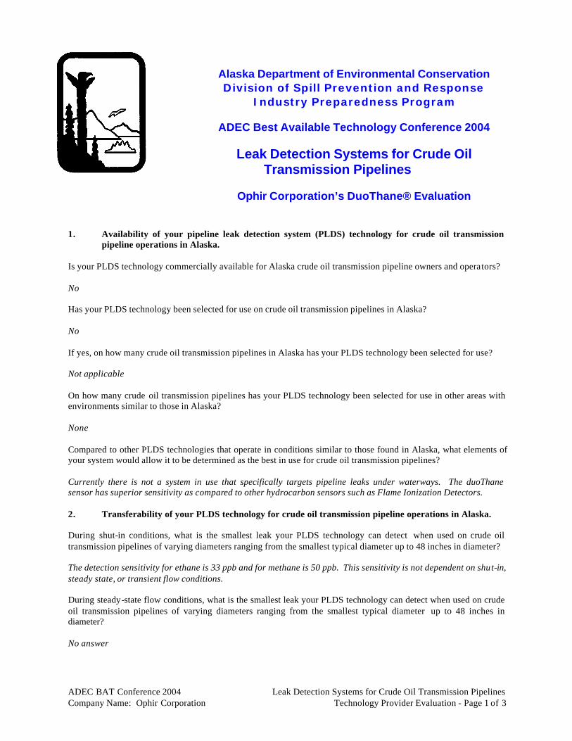
ADEC BAT Conference 2004 Leak Detection Systems for Crude Oil Transmission Pipelines Company Name: Ophir Corporation Technology Provider Evaluation - Page 1 of 3
Alaska Department of Environmental Conservation Division of Spill Prevention and Response
Industry Preparedness Program
ADEC Best Available Technology Conference 2004
Leak Detection Systems for Crude Oil Transmission Pipelines
Ophir Corporation’s DuoThane® Evaluation
1. Availability of your pipeline leak detection system (PLDS) technology for crude oil transmission
pipeline operations in Alaska. Is your PLDS technology commercially available for Alaska crude oil transmission pipeline owners and operators? No Has your PLDS technology been selected for use on crude oil transmission pipelines in Alaska? No If yes, on how many crude oil transmission pipelines in Alaska has your PLDS technology been selected for use? Not applicable On how many crude oil transmission pipelines has your PLDS technology been selected for use in other areas with environments similar to those in Alaska? None Compared to other PLDS technologies that operate in conditions similar to those found in Alaska, what elements of your system would allow it to be determined as the best in use for crude oil transmission pipelines? Currently there is not a system in use that specifically targets pipeline leaks under waterways. The duoThane sensor has superior sensitivity as compared to other hydrocarbon sensors such as Flame Ionization Detectors. 2. Transferability of your PLDS technology for crude oil transmission pipeline operations in Alaska. During shut-in conditions, what is the smallest leak your PLDS technology can detect when used on crude oil transmission pipelines of varying diameters ranging from the smallest typical diameter up to 48 inches in diameter? The detection sensitivity for ethane is 33 ppb and for methane is 50 ppb. This sensitivity is not dependent on shut-in, steady state, or transient flow conditions. During steady-state flow conditions, what is the smallest leak your PLDS technology can detect when used on crude oil transmission pipelines of varying diameters ranging from the smallest typical diameter up to 48 inches in diameter? No answer

ADEC BAT Conference 2004 Leak Detection Systems for Crude Oil Transmission Pipelines Company Name: Ophir Corporation Technology Provider Evaluation - Page 2 of 3
During transient flow conditions, what is the smallest leak your PLDS technology can detect when used on crude oil transmission pipelines of varying diameters ranging from the smallest typical diameter up to 48 inches in diameter? No Answer What is the coldest temperature at which your PLDS technology can operate effectively (including accurate product release alarming, accurate identification of leak location, and accurate identification of leak rate)? Approximately -60°F Is your PLDS technology suitable for use on both above and below-grade crude oil transmission pipelines? Yes 3. Effectiveness of your PLDS technology for crude oil transmission pipeline operations in Alaska. In what way will use of your PLDS technology provide increased spill prevention or other environmental benefits? Early leak detection; specifically of spills under waterways. What is the detection time for the smallest leak your PLDS technology can detect on crude oil transmission pipelines of varying diameters ranging from the smallest typical diameter up to 48 inches in diameter during shut-in conditions? The detection time for shut-in, steady-state and transient flow conditions is dependent on the product transport time from the pipe, through the water, and into the atmosphere. It may also be dependent on the wind direction, current speed and the surface condition of the water (i.e. broken ice). What is the detection time for the smallest leak your PLDS technology can detect on crude oil transmission pipelines of varying diameters ranging from the smallest typical diameter up to 48 inches in diameter during steady-state flow conditions? No Answer What is the detection time for the smallest leak your PLDS technology can detect on crude oil transmission pipelines of varying diameters ranging from the smallest typical diameter up to 48 inches in diameter during transient flow conditions? Describe the leak location accuracy available from your PLDS technology when the smallest leaks described above for shut-in, steady-state, and transient flow conditions are detected. The leak location can be defined down to the length of pipe running under the waterway. 4. Cost to implement your PLDS technology on Alaska crude oil transmission pi pelines. What is the range of costs in rough order magnitude (ROM) for the installation of your PLDS technology on crude oil transmission pipelines with varying complexities and of varying diameters ranging from the smallest typical diameter up to 48 inches in diameter? $10K/unit when in production What is the range of costs in ROM for the operation (including training), and maintenance of your PLDS technology on crude oil transmission pipelines with varying complexities and of varying diameters ranging from the smallest typical diameter up to 48 inches in diameter on an annual basis? $2K/unit/year operation

ADEC BAT Conference 2004 Leak Detection Systems for Crude Oil Transmission Pipelines Company Name: Ophir Corporation Technology Provider Evaluation - Page 3 of 3
5. Compatibility with existing operations and technologies in use on existing Alaska crude oil transmission pipelines.
Can your PLDS technology interface with Supervisory Control and Data Acquisition (SCADA) systems? Yes If not compatible with SCADA systems, what system does your PLDS technology use and how is it compatible with conventional systems? Not applicable 6. Practical feasibility, in terms of engineering and other operational aspects, to implement your PLDS
technology on Alaska crude oil transmission pipelines. How are false alarms detected and corrected by the algorithms used in your PLDS technology? Optical spectral correlation uniquely detects methane and ethane and all other hydrocarbons and flammable gases are rejected. How often do the software and meters used in your PLDS technology need to be calibrated or replaced? Not applicable - self calibrating How many variables and how user friendly is your PLDS technology display for operations to detect a leak? Very user friendly - programmable system set-up What are the training requirements and training period for operators to become efficient in leak pattern recognition on your PLDS technology display? Low Does your PLDS technology accommodate product measurement and inventory compensation for various corrections (i.e., temperature, pressure, and density)? Not applicable 7. Environmental impact of your PLDS technology must not offset environmental benefits. Will operation of your PLDS technology have any negative impacts on air quality, land, or water quality? No Does your PLDS have energy requirements that might cause a negative environmental impact? No

APPENDIX C
LEAKNET™ BY EFA TECHNOLOGY, INC.

Category 1 – Leak Detection Systems For Crude Oil Transmission Pipelines
Leak Net (Ed Farmer & Associates) Abstract Best Available Technologies Conference, May 27-28, 2004 Egan Convention Center, Anchorage, AK
LeakNet (EFA Technologies, Inc.)
Ed Farmer and Stacey Daniels LEAKNET is a unique approach to leak detection that integrates three complementary, fully independent methods of leak detection into a single package: dynamic line monitoring via Pressure Point Analysis (PPA)TM and MassPackTM and static line monitoring via Static PPA. All three can be used at the same time, with each playing a supporting role in monitoring the line, or with any one of them as the sole leak detection methodology. Pressure Point Analysis (PPA) TM is an “event” detection methodology that looks for characteristic changes in pressure and flow rate (internal energy and momentum) to identify a leak. Patterns containing the characteristic signature of a leak are extracted from the normal hydraulic background noise by patented, real-time statistical algorithms. Proprietary pattern recognition algorithms and intelligent alarm processing separate leaks from normal transient events. MassPackTM is EFA’s proprietary dynamic meter balance module. It is defined under API 1130 as a “modified volume balance” methodology. Highly user configurable, it is part of the standard LEAKNET product. While it may use the same meter and pressure inputs as PPA, it uses the data in a completely different way providing an independent secondary methodology. Using both PPA and MassPack together provides the highest level of reliability and leak detection capability available on the market. The key to a successful leak detection project is the corporate commitment to make it happen. The second most important ingredient is providing adequate resources -- especially the right people. The availability of these people plus the infrastructure and technical resources have made it possible to accomplish great things. But most importantly, the commitment of the operating companies to “do it right” is, without any doubt, the greatest factor in ensuring the success of pipeline monitoring. LEAKNET is a standard product available in sizes ranging from 5 inputs up to 1,000 inputs and typically uses the same pressure transmitters and flow meters already installed on the pipeline. Update rates can be between 6-10 seconds for leak detection. Leak location requires a consistent update rate of 0.25-second, but will, in some cases, operate acceptably with a 0.50-second update rate. Optimal detection and location performance is obtained when the analog to digital resolution of the field instruments is 16-bit.
LEAKNET™ can be used to continuously or intermittently monitor flowing or static pipelines.
3-inch refinery inter-unit piping
A few hundred feet of in-facility piping

ADEC BAT Conference 2004 Leak Detection Systems for Crude Oil Transmission Pipelines Company Name: EFA Technology Technology Provider Evaluation - Page 1 of 6
Alaska Department of Environmental Conservation Division of Spill Prevention and Response
Industry Preparedness Program
ADEC Best Available Technology Conference 2004
Leak Detection Systems for Crude Oil Transmission Pipelines
ADEC’s Evaluation Committee Appraisal of
EFA Corporation’s LeakNet Evaluation 1. Availability of your pipeline leak detection system (PLDS) technology for crude oil
transmission pipeline operations in Alaska. Is your PLDS technology commercially available for Alaska crude oil transmission pipeline owners and operators? Yes, LEAKNET is commercially available for Alaska crude oil transmission pipeline owners and operators. It has been successfully installed in Alaska and around the world for over 25 years. It currently holds two BAT certifications from the State of Alaska and has the largest number of installed leak detection systems on the North Slope. Has your PLDS technology been selected for use on crude oil transmission pipelines in Alaska? Yes, we monitor many crude oil transmission pipelines in Alaska. If yes, on how many crude oil transmission pipelines in Alaska has your PLDS technology been selected for use? We have currently been selected by over 12 sites to monitor over 20 transmission lines. A short user’s list is attached. On how many crude oil transmission pipelines has your PLDS technology been selected for use in other areas with environments similar to those in Alaska? LEAKNET is currently monitoring over 400 pipelines worldwide. The terrain ranges from arctic to swamp land, desert to subsea applications. Some are extremely environmentally sensitive areas incorporating both high heat and below freezing temperatures. The only limiting factor for LEAKNET is the field instrumentation and how it is installed. The LEAKNET computer is maintained in an area suitable for personnel. The calculations for leak detection are not impacted by different climate conditions. Compared to other PLDS technologies that operate in conditions similar to those found in Alaska, what elements of your system would allow it to be determined as the best in use for crude oil transmission pipelines? LEAKNET is designed to use conventional pipeline instruments. All performance expectations depend only on common instruments performing in their usual manner. Additionally, LEAKNET is “fault-tolerant.” When an instrument fails, the leak detection algorithms continue working as well as they can with the data that continues to be available. This usually results in a decrease in nuisance alarm immunity and perhaps some reduction in sensitivity, but operation continues to the greatest extent possible. Pressure Point

ADEC BAT Conference 2004 Leak Detection Systems for Crude Oil Transmission Pipelines Company Name: EFA Technology Technology Provider Evaluation - Page 2 of 6
Analysis (PPA) is extremely tolerant of instrument errors as long as the instruments are performing, the readings change when the underlying parameters change. This not only increases reliability and effectiveness, it also minimizes maintenance expense. Once an instrument is returned to service, the leak detection algorithms restore use of the additional data. 2. Transferability of your PLDS technology for crude oil transmission pipeline operations in
Alaska. During shut-in conditions, what is the smallest leak your PLDS technology can detect when used on crude oil transmission pipelines of varying diameters ranging from the smallest typical diameter up to 48 inches in diameter? See below. During steady-state flow conditions, what is the smallest leak your PLDS technology can detect when used on crude oil transmission pipelines of varying diameters ranging from the smallest typical diameter up to 48 inches in diameter? See below. During transient flow conditions, what is the smallest leak your PLDS technology can detect when used on crude oil transmission pipelines of varying diameters ranging from the smallest typical diameter up to 48 inches in diameter? The sensitivity under static (shut-in) conditions is somewhat dependent on the line volume. PPA can detect leaks on losses as small as 14 ml out of 7,000 gallons, 0.1 gallon out of 116,000 gallons and 4.5 PPM on larger lines. It can detect existing leaks and those that have just occurred. It can only locate the position of leaks that occur while the line is being monitored. Under dynamic conditions sensitivity depends in part on the amount of hydraulic noise at the measurement points and where the pump or compressor is operating on its curve. Every pipeline is different, so sensitivity will vary depending on the resident conditions. Just to provide a reference point, a well designed application with the equipment running at high efficiency and instruments in hydraulically quiet locations can have sensitivity down in the 0.3 percent of flow range or even less. Sensitivity degrades as the line conditions degrade. Sensitivity in the range of 0.5 to 1.0 percent of flow is pretty common. In some applications (e.g., BP Northstar) leaks smaller than 0.08% of flow can be detected. What is the coldest temperature at which your PLDS technology can operate effectively (including accurate product release alarming, accurate identification of leak location, and accurate identification of leak rate)? As long as product can flow and be effectively measured we can perform leak detection with MassPack modified volume balance. The effect on PPA is generally negligible because due to thermal mass issues, the temperature can't change very much over the time it takes to detect a leak. Is your PLDS technology suitable for use on both above and below-grade crude oil transmission pipelines? Yes, LEAKNET is suitable for both above and below grade pipelines. 3. Effectiveness of your PLDS technology for crude oil transmission pipeline operations in
Alaska. In what way will use of your PLDS technology provide increased spill prevention or other environmental benefits? LEAKNET provides three methods of leak detection in a single package. During flowing conditions it uses both PPA and MassPack . Response time to a leak, whether in a liquid application or vapor is only limited

ADEC BAT Conference 2004 Leak Detection Systems for Crude Oil Transmission Pipelines Company Name: EFA Technology Technology Provider Evaluation - Page 3 of 6
by the speed of sound in the fluid. SmartPoint intelligent alarm processing limits alarms to actual leak events. A fast response time coupled with 100% nuisance alarm free operation makes it possible for the operator to limit the duration, and therefore the spill volume of the leak. Locator provides tight leak location estimates, which facilitates a rapid mitigation of the damage. What is the detection time for the smallest leak your PLDS technology can detect on crude oil transmission pipelines of varying diameters ranging from the smallest typical diameter up to 48 inches in diameter during shut-in conditions? See below. What is the detection time for the smallest leak your PLDS technology can detect on crude oil transmission pipelines of varying diameters ranging from the smallest typical diameter up to 48 inches in diameter during steady-state flow conditions? See below. What is the detection time for the smallest leak your PLDS technology can detect on crude oil transmission pipelines of varying diameters ranging from the smallest typical diameter up to 48 inches in diameter during transient flow conditions? PPA is a real-time leak detection methodology that can go into alarm as soon as the expansion wave associated with a leak reaches the end point instruments. The length of the pipeline and the speed of sound in the product determine how long this will take. The speed of sound in crude oil typically ranges from 975 meters (3,200 feet) per second to 1160 meters (3,800 feet) per second. When the pressure/flow disturbance of the leak is very close to the moment-by-moment fluctuations that create normal line noise, PPA takes longer to detect the leak. On pipelines operated by the US Strategic Petroleum Reserve that use brine injection to lift oil out of underground salt domes PPA normally detects leaks on losses of about 0.7-percent of flow. (As an example, 0.7 barrel out of a 36-inch, 60 Km pipeline containing ~238,000 barrels in under 3 minutes.) MassPack responds to the leak only after the event has traveled to both ends of the line and the measurable difference exceeds the alarm threshold. Depending on the size of the leak this may take minutes to an hour. MassPack includes optional line pack correction that can be turned on by the customer if the line has packing/unpacking issues associated with it. This reduces the size of the alarm threshold required under these conditions. Describe the leak location accuracy available from your PLDS technology when the smallest leaks described above for shut-in, steady-state, and transient flow conditions are detected. LEAKNET’s leak location option, Locator, operates from the PPA module. Locator requires 0.25-second updates in liquids and can tolerate slower updates in gas because the rate of change is so much slower in gaseous conditions. Unlike PPA, Locator also requires the updates to be at consistent intervals, which may require the field data to be transmitted in buffered “data packets” to a data concentrator that would parse the updates out for LEAKNET and make them available in a PLC or some other suitable device capable of handling the needed processing speed. When a leak is detected the Locator program accesses the 0.25-second data PPA has stored in cache for the pressure inputs. It compares the data for the end point pressure instruments and identifies the readings that represent the first evidence of a leak at each instrument. Using an internally calculated speed of sound in the product Locator completes a time distance calculation that includes weighted interpolation of the results to generate a location with a guaranteed accuracy of no less than 600 meters.

ADEC BAT Conference 2004 Leak Detection Systems for Crude Oil Transmission Pipelines Company Name: EFA Technology Technology Provider Evaluation - Page 4 of 6
4. Cost to implement your PLDS technology on Alaska crude oil transmission pipelines. What is the range of costs in rough order magnitude (ROM) for the installation of your PLDS technology on crude oil transmission pipelines with varying complexities and of varying diameters ranging from the smallest typical diameter up to 48 inches in diameter? This is difficult to quantify, as different applications will have different initial costs. A short pipeline might only require monitoring four field instruments, which we refer to as points. A longer line might require forty points or even seventy-five points. Because of this variability in need, LEAKNET is available in standard sizes – 5 points, 10 points, 25 points, 50 points, 75 points, 100 points, up to 1,000 points. Larger size systems cost more than the smaller ones, but the per point cost decreases as the system size increases. In addition to the number of points being purchased, there are optional features available in LEAKNET that a pipeline owner may elect to include, which will add to the price. Beyond that, a system receiving data directly from SCADA will be less expensive than one collecting its own field data via modems and RTU boxes will add to the cost. Unlike many other leak detection systems all of the points purchased in a LEAKNET system are immediately available to the owner without any additional licensing fees as they are brought on line. The price initially paid for the system is the actual cost. What is the range of costs (ROM) for the operation (including training), and maintenance of your PLDS technology on crude oil transmission pipelines with varying complexities and of varying diameters ranging from the smallest typical diameter up to 48 inches in diameter on an annual basis? LEAKNET does not result in additional maintenance costs for the owner. The software does not require the maintenance normally associated with custom transient model systems. LEAKNET is also unique in the industry because EFA does not charge an annual fee for customer service. EFA provides a no cost 24-hour help line. We can do this because LEAKNET is a product using standard software, which does not require the maintenance and debugging normally associated with custom and transient model systems. The Dell computer only needs the routine care given to any PC. The field instruments used by PPA do not need to be recalibrated even as frequently as recommended by the API Standard Practices. If MassPack is being used, the meters require only the standard calibration and proving indicated by the API metering practices. Optional features can be added at any time. Upgrades are available at any time. The first year’s software update is provided at no cost to the owner, should an update occur. 5. Compatibility with existing operations and technologies in use on existing Alaska crude oil
transmission pipelines. Can your PLDS technology interface with Supervisory Control and Data Acquisition (SCADA) systems? Yes, LEAKNET is compatible with most SCADA systems. We have yet to encounter a situation in which we were unable to communicate effectively with SCADA. If not compatible with SCADA systems, what system does your PLDS technology use and how is it compatible with conventional systems? See above.

ADEC BAT Conference 2004 Leak Detection Systems for Crude Oil Transmission Pipelines Company Name: EFA Technology Technology Provider Evaluation - Page 5 of 6
6. Practical feasibility, in terms of engineering and other operational aspects, to implement your PLDS technology on Alaska crude oil transmission pipelines.
How are false alarms detected and corrected by the algorithms used in your PLDS technology? The individual points in the system provide only an alarm/no alarm status. The status conditions are combined into logical arguments that provide intelligent alarm processing through SmartPoint, a standard feature in LEAKNET. SmartPoint is LEAKNET’s intelligent alarm processor and is LEAKNET’s most powerful way of eliminating false alarms. Each SmartPoint operating within LEAKNET is created by defining a logical relationship among a collection of PPA and/or MassPack points. Any SmartPoint can use any PPA point, any MassPack accumulator and any other configured SmartPoint to create this logical relationship. Each SmartPoint monitors all of its component points to see if the alarm logic of the relationship is satisfied. When it is, a fully qualified alarm is provided for the operator. PPA points, MassPack accumulators and other SmartPoint’s may be used over and over to create as many SmartPoint’s as needed. Configuration of SmartPoint arguments is done in a point-and-click -editor window and takes only minutes to complete or edit. It should be noted that the flow instruments required for nuisance alarm free operation only need to be repeatable rather than highly accurate and can be provided by inexpensive, strap-on ultrasonic flow meters. How often do the software and meters used in your PLDS technology need to be calibrated or replaced? Regular and repeated calibration of the instruments is not necessary in order for LEAKNET to function correctly. The field instruments used by PPA do not need to be recalibrated even as frequently as recommended by the API Standard Practices. Repeatability is more important than accuracy. Instruments only need to respond to the change generated by the target size leak. If the instruments can “see” it, LEAKNET can detect it. The instruments required to produce acceptable performance only need to be modern, electronic equipment with good sensitivity and repeatability (Flow - +/-0.2% to +/-0.5%) (Pressure - +/-0.5% to +/-0.075% accuracy) ranges so readings are normally in the upper 2/3rds of the calibrated span. How many variables and how user friendly is your PLDS technology display for operations to detect a leak? LEAKNET is used in a wide variety of operating situations, some of which are in very remote locations that do not have SCADA engineers available. The operator interface and internal logic is designed to make LEAKNET easily understood and user friendly to the front line operator. SmartPoint, LEAKNET’s intelligent alarm processing feature incorporated in the PPA module does the leak/no leak analysis in real time. If the process is not upset and all instruments are operating, a SmartPoint alarm does not require re-evaluation by the Operator. As an option, the alarm conditions detected by LEAKNET may be passed to the SCADA system for display. What are the training requirements and training period for operators to become efficient in leak pattern recognition on your PLDS technology display? Our Standard Operator and System Administrator training class for LEAKNET is typically conducted using live inputs. The training class teaches personnel how to identify the changes in pressure and flow that can only be true in the presence of a leak for a given section of pipeline. Once the Operators correctly enter the logic into SmartPoint, all process changes are correctly and automatically filtered out. The Operator is given all the tools and training necessary to add new pipeline segments, set up the intelligent alarm processing, and tune the system all without continued assistance from EFA. All alarms and events are logged and available for review and corrective action by operators and administrators. There is no on-going software maintenance or costly customer support required. EFA does provide on-going support via telephone, email and fax at no cost to the Customer. Training for an operator typically takes 8 hours. Administrator training takes about two (2) days. Depending on the philosophy of the site, a facility trainer (CPM analyst) may be trained first and coached

ADEC BAT Conference 2004 Leak Detection Systems for Crude Oil Transmission Pipelines Company Name: EFA Technology Technology Provider Evaluation - Page 6 of 6
through the training of the operators and administrators. Training is provided for all options purchased by the Users. Does your PLDS technology accommodate product measurement and inventory compensation for various corrections (i.e., temperature, pressure, and density)? LEAKNET uses both pressure and/or mass as a key measurement for leak detection. Pressure Point Analysis, PPA, does not benefit by receiving either temperature or density measurement data. In some cases temperature and density measurement data may assist MassPack. 7. Environmental impact of your PLDS technology must not offset environmental benefits. Will operation of your PLDS technology have any negative impacts on air quality, land, or water quality? No, just the opposite, a fast response time coupled with 100% nuisance alarm free operation makes it possible for the operator to limit the duration, and therefore the spill volume, of the leak. Locator provides tight leak location estimates, which facilitates a rapid mitigation of the damage. Does your PLDS have energy requirements that might cause a negative environmental impact? No, LEAKNET’s power requirements are equivalent to an ordinary PC.

APPENDIX D
WAVEALERT® BY ACOUSTIC SYSTEMS INCORPORATED

Category 1 – Leak Detection Systems For Crude Oil Transmission Pipelines
Wave Alert (Acoustic Systems) Abstracts Best Available Technologies Conference, May 27-28, 2004 Egan Convention Center, Anchorage, AK
WaveAlert® (Acoustic Systems)
WaveAlert® Acoustic Leak Detection System
Dr. Bao-Wen and Marion Recane Rising oil prices, environmental awareness and focus on prevention of catastrophic accidents have brought to the forefront the need for a truly reliable, fast, accurate, and sensitive on-line real-time leak detection system (LDS). In evaluating on-line real-time leak detection systems for environmental concerns, four important criteria are applied, namely: detection time, sensitivity, leak location accuracy, and most importantly – reliability (or false alarm rate). In addition, factors such as the ease of system installation, operation and maintenance are taken into account. Based on these considerations, ASI’s WaveAlert® ALDS has shown to be the most effective and reliable leak detection system for single phase gas, liquid, as well as multiphase flow pipelines. At the instant of a breakdown of the pressure boundary (leak), the release of the elastic force couples with the system fluid to create a transient acoustic wave. This acoustic wave travels outward from the source at the speed of sound for that fluid, guided by the pipe wall, to be detected by sensitive acoustic sensors situated at the ends of the pipeline and some intermediate valve sites. From times of arrival of the acoustic waves at different sensor locations, the location of the leak is determined. With the use of GPS receivers, the leak detection and time stamping functions are performed at each local processor, the ALDS system will continue to detect leaks in case of communication fault or loss of communication. Based on the advanced proprietary and patented technology, the WaveAlert® ALDS has been proven not only good for single phase pipelines (both gas and liquid pipelines) but also performed very well in multiphase flow pipelines (see recent publications-- IPC04-0162, “well succeeded application of acoustic technology for pipelines [single phase and multi phases] leak detection...”) and recognized as the most effective LDS for multiphase (such as crude oil+gas+water) application for both offshore and onshore pipelines. ASI’s WaveAlert® ALDS has improved leak detection technology from many years of field proven applications providing the quickest leak detection (less than 1 minute, typically 15 to 30 seconds), high sensitivity (0.1% of total flowrate), precise leak location accuracy (+/- 35 m), and low false alarm rate (typically one alarm per year or less). The advanced data processing techniques as well as powerful proprietary structure established from over 20 years of experimental and field leak tests not only drastically reduce the false alarm rate, but also significantly improve the sensitivity and leak location accuracy. Due to its low false alarm rate and reliable performance in actually detecting and locating leaks under various operation conditions, ASI’s ALDS is the ONLY LDS successfully used for automatic valve shut-off upon detection of leak. For example, in November 2000 a WaveAlert® VII system installed in Australia detected and located a leak on an LPG pipeline and automatically shut-in the pipeline within one minute of leak occurrence preventing potential casualties and environmental disaster. The WaveAlert ALDS system was installed on several pipelines in South America in order to quickly detect and precisely locate theft from the pipeline. The WaveAlert® ALDS system has successfully assisted in capturing several groups of refined products thieves and proven to be a very effective pipeline theft detection and deterrent system. Since 2001, a series of extensive tests have been carried out on the WaveAlert® system for many multiphase flow on-shore and off-shore pipelines including leak tests submersed in a 20 meter water column to simulate leaks in subseas conditions. After successfully concluding these tests, several WaveAlert systems were installed to monitor over 40 off-shore and on-shore pipelines. Finally, we quote from two independent articles published by the users of the ASI ALDS, one from the International Pipeline Conference, IPC02-0283 “leak detection systems for multiphase flow – moving forward,” “Multiphase flow is one of the most difficult situations, for leak detection in pipelines…many technologies are quite ineffective for multiphase flow...the systems based on prediction approaches, will be unreliable, inaccurate and insensitive.” On the other hand, “the Acoustic Leak Detection System is an exception…After the tests were implemented, data showed the system had capability of detecting and locating holes ranging from 0.2 to 0.5 inches…average error on the leak location was of +/- 30m to 200m, which was considered within the range of expected and acceptable results, especially for the multiphase flow. The detecting and locating time is very short, sometimes smaller than 15 seconds. Since the first tests, the system was left in operation, so as to evaluate its stability to spurious alarms. Since then (2001), no false alarms were

Wave Alert (Acoustic Systems) Abstracts Best Available Technologies Conference, May 27-28, 2004 Egan Convention Center, Anchorage, AK
generated by this system.” “The system is very sensitive, even for multiphase flow. Not only multiphase flow pipelines are suitable for this technology…almost all lines may use this technique, especially gas pipelines.” Another independent paper also gave very strong endorsement (translated directly from German):- “Leak Detection in Sour Gas Pipelines by a Pressure Wave Recording System” Fischer, F., Oil, Gas, Coal. 110. year 1994, vol. 6, pp 261-264. “In Sudoldenburg, Sour Gas with a H2S content up to 35% by volume is transported over a pipeline system approximately 400 km long to a central treatment plant...ASI, together with BEB extended the leak detection system from liquid to gas pipelines...Considering this, an unobjectionable proof of successful leak detection function was demonstrated by this ASI leak detection system.”

ADEC BAT Conference 2004 Leak Detection Systems for Crude Oil Transmission Pipelines Company Name: Acoustic Systems Technology Provider Evaluation - Page 1 of 4
Alaska Department of Environmental Conservation Division of Spill Prevention and Response
Industry Preparedness Program
ADEC Best Available Technology Conference 2004
Leak Detection for Crude Oil Transmission Pipelines
Acoustic Systems’ Wave Alert Evaluation
1. Availability of your pipeline leak detection system (PLDS) technology for crude oil transmission
pipeline operations in Alaska. Is your PLDS technology commercially available for Alaska crude oil transmission pipeline owners and operators? Yes Has your PLDS technology been selected for use on crude oil transmission pipelines in Alaska? No If yes, on how many crude oil transmission pipelines in Alaska has your PLDS technology been selected for use? On how many crude oil transmission pipelines has your PLDS technology been selected for use in other areas with environments similar to those in Alaska? Over 30 Compared to other PLDS technologies that operate in conditions similar to those found in Alaska, what elements of your system would allow it to be determined as the best in use for crude oil transmission pipelines? The most reliable (fewest false alarm), quickest and most accurate leak detection and location system available. 2. Transferability of your PLDS technology for crude oil tr ansmission pipeline operations in Alaska. During shut-in conditions, what is the smallest leak your PLDS technology can detect when used on crude oil transmission pipelines of varying diameters ranging from the smallest typical diameter up to 48 inches in diameter? Depends on pipeline pressure and sensor spans, the detectable leak sizes ranging from 0.1 to 0.4 inch for pipelines ranging from the smallest typical diameter up to 48 inches in diameter. During steady-state flow conditions, what is the smallest leak your PLDS technology can detect when used on crude oil transmission pipelines of varying diameters ranging from the smallest typical diameter up to 48 inches in diameter? Depends on pipeline pressure and sensor spans, the detectable leak sizes ranging from 0.12 to 0.6 inch for pipelines ranging from the smallest typical diameter up to 48 inches in diameter. During transient flow conditions, what is the smallest leak your PLDS technology can detect when used on crude oil transmission pipelines of varying diameters ranging from the smallest typical diameter up to 48 inches in diameter?

ADEC BAT Conference 2004 Leak Detection Systems for Crude Oil Transmission Pipelines Company Name: Acoustic Systems Technology Provider Evaluation - Page 2 of 4
Depends on pipeline pressure and sensor spans, the detectable leak sizes ranging from 0.15 to 0.75 inch for pipelines ranging from the smallest typical diameter up to 48 inches in diameter. What is the coldest temperature at which your PLDS technology can operate effectively (including accurate product release alarming, accurate identification of leak location, and accurate identification of leak rate)? The WaveAlert ALDS has been tested down to -40°C and successfully used in Russia, Siberia. Is your PLDS technology suitable for use on both above and below-grade crude oil transmission pipelines? Yes 3. Effectiveness of your PLDS technology for crude oil transmission pipeline operations in Alaska. In what way will use of your PLDS technology provide increased spill prevention or other environmental benefits? ASI's ALDS is the quickest, most accurate, and most reliable leak detection and location system available. This is the only system so reliable (low false alarm rate) which allows and has been used for automatic valve shut-off upon detecting leaks. It is the only system with proven record of actually detected leak and automatically shut-off pipelines, prevented potential disasters, which supports the potential of automatic valve shut-off application to shut down the pipeline, stop leakage within one to two minutes of leak occurring. This provides the most practical way to limit environmental damage from a pipeline leak. What is the detection time for the smallest leak your PLDS technology can detect on crude oil transmission pipelines of varying diameters ranging from the smallest typical diameter up to 48 inches in diameter during shut-in conditions? Depends on distance between sensors, typically less than 60 seconds (the ASI's ALDS detection time is independent of leak size). What is the detection time for the smallest leak your PLDS technology can detect on crude oil transmission pipelines of varying diameters ranging from the smallest typical diameter up to 48 inches in diameter during steady-state flow conditions? Depends on distance between sensors, typically less than 60 seconds (the ASI's ALDS detection time is independent of leak size). What is the detection time for the smallest leak your PLDS technology can detect on crude oil transmission pipelines of varying diameters ranging from the smallest typical diameter up to 48 inches in diameter during transient flow conditions? Depends on distance between sensors, typically less than 60 seconds (the ASI's ALDS detection time is independent of leak size). Describe the leak location accuracy available from your PLDS technology when the smallest leaks described above for shut-in, steady-state, and transient flow conditions are detected. Depends on distance between sensors, typical leak location accuracy is +/- 30 meters for all conditions (shut-in, steady state, and transient). 4. Cost to implement your PLDS technology on Alaska crude oil transmission pipelines. What is the range of costs in rough order magnitude (ROM) for the installation of your PLDS technology on crude oil transmission pipelines with varying complexities and of varying diameters ranging from the smallest typical diameter up to 48 inches in diameter?

ADEC BAT Conference 2004 Leak Detection Systems for Crude Oil Transmission Pipelines Company Name: Acoustic Systems Technology Provider Evaluation - Page 3 of 4
Depends on the length of the pipeline and performance requirement, the typical cost ranges from $80,000 and up. What is the range of costs in ROM for the operation (including training), and maintenance of your PLDS technology on crude oil transmission pipelines with varying complexities and of varying diameters ranging from the smallest typical diameter up to 48 inches in diameter on an annual basis? Training is included in the above system cost, cost for operation and maintenance is very low since no calibration is required and the system comes with a one year warranty. 5. Compatibility with existing operations and technologies in use on existing Alaska crude oil
transmission pipelines. Can your PLDS technology interface with Supervisory Control and Data Acquisition (SCADA) systems? Yes If not compatible with SCADA systems, what system does your PLDS technology use and how is it compatible with conventional systems? 6. Practical feasibility, in terms of engineering and other operational aspects, to implement your PLDS
technology on Alaska crude oil transmission pipelines. How are false alarms detected and corrected by the algorithms used in your PLDS technology? During installation, filters and algorithms are fine-tuned to provide extreme low false alarm rate (typical less than one per year). This is achieved by ASI's many proprietary data processing algorithms as well as multilayer redundant and cross verification structure. One of the most effective is the patented signature recognition method based on finger-print signature data developed over 20 years of field experience and experimental studies. This system is so reliable (detect leaks under all conditions with low false alarm rate), it is the only PLDS actually used for automatic valve shut-off and has proven record of actually detecting and locating leaks, shutting down the pipelines and preventing potential disasters. How often do the software and meters used in your PLDS technology need to be calibrated or replaced? No calibration is required unless product or configuration is changed. How many variables and how user friendly is your PLDS technology display for operations to detect a leak? All variables and parameters are set during installation and commissioning. No adjustments are required after this. System is very easy to use, requires no interpretation of data. All leaks will be "definitely" reported and located without any guessing or interpretation of statistical probability (any alarm without a true leak is considered as a false alarm). Normally, after the commissioning, the system can operate free of attention. This is the reason that this system can be and has been successfully used for automatic valve shut-off upon detecting leaks. What are the training requirements and training period for operators to become efficient in leak pattern recognition on your PLDS technology display? Training typically requires 1/2 day. No operator pattern recognition. System provides LEAK/NO LEAK output (no statistical “guessing game” and NO NEED for expert operator to interpret the data). Does your PLDS technology accommodate product measurement and inventory compensation for various corrections (i.e., temperature, pressure, and density)? Since the ALDS system does NOT detect leak based on "conservation law," it does NOT require any correction or compensation based on temperature, pressure, or density in order to detect and accurately locate the leak.

ADEC BAT Conference 2004 Leak Detection Systems for Crude Oil Transmission Pipelines Company Name: Acoustic Systems Technology Provider Evaluation - Page 4 of 4
However, if customer prefers, a modeling based system can be (and has been applied) added to the ALDS as an integrated system, which will also provide product measurement and tracking as well as inventory compensation. 7. Environmental impact of your PLDS technology must not offset environmental benefits. Will operation of your PLDS technology have any negative impacts on air quality, land, or water quality? No Does your PLDS have energy requirements that might cause a negative environmental impact? No

APPENDIX E
SONOLICATE®/ULTRASONIC FLOWMETERS BY CONTROLOTRON

Category 1 – Leak Detection Systems For Crude Oil Transmission Pipelines
Ultrasonic Flowmeters (Controlotron) Abstract Best Available Technologies Conference, May 27-28, 2004 Egan Convention Center, Anchorage, AK
Ultrasonic Flowmeters (Controlotron)
Sid Douglas
Controlotron’s Ultrasonic Flowmeters technology operates by passing sound waves through the pipe wall and liquids being delivered through the pipeline. The time-difference between upstream and downstream transmissions are directly proportional to the velocity of the liquid or liquids flowing in the pipe. The system can be installed for purposes of leak detection with no penetration into the pipeline and operates on any pipeline from 4 to 120 inches in diameter. Instruments of this class have been in operation in the harsh environment of Alaska’s North Slope since 1983. The measurement instruments utilized are designed to replace intrusive PD meters, turbine meters, and Coriolis meters. Based upon the incorporation of ultrasonic meters, the systems can operate over a wide range of temperature and environmental conditions. The flow elements have been in use at BP production sites in outdoor environments since 1985. The technology is already in place on many of the crude oil, water, and product pipelines in Alaska. The ease of non-intrusive installation and software compatibility with all SCADA systems makes this approach most easily adapted to existing pipeline applications. Because of the extreme sensitivity of the system components, very small leaks (~1% of rate) can be found in less than 5 minutes. The operation of the system provides differentiation of leak alarms, pressure transients, and line backing events. The flow instruments are most compatible with crude oil and multi-product pipelines, since the outputs obtained include not only flow rate/flow total, but also viscosity, density/API, and are bi-directional in operation. The leak detection software is compatible either as a free-standing system or with existing SCADA systems. The system is completely non-intrusive in design, can be installed in days, and ready for operation of leak detection and location as soon as it is possible to receive the data via the customer provided communication network. Included at no additional cost with the system is the ability to provide batch tracking and pig tracking, and interface detection.
Controlotron’s System 1010 DV, a clamp-on, transit-time flowmeter that utilizes
Controlotron’s award-winning Wide-Beam™ transducer technology

ADEC BAT Conference 2004 Leak Detection Systems for Crude Oil Transmission Pipelines Company Name: Controlotron Technology Provider Evaluation - Page 1 of 4
Alaska Department of Environmental Conservation Division of Spill Prevention and Response
Industry Preparedness Program
ADEC Best Available Technology Conference 2004
Leak Detection System for Crude Oil Transmission Pipelines
Controlotron’s Ultrasonic Flowmeters Evaluation
1. Availability of your pipeline leak detection system (PLDS) technology for crude oil transmission
pipeline operations in Alaska. Is your PLDS technology commercially available for Alaska crude oil transmission pipeline owners and operators? Yes, systems are installed world wide on both crude and refined product lines. Has your PLDS technology been selected for use on crude oil transmission pipelines in Alaska? Not yet If yes, on how many crude oil transmission pipelines in Alaska has your PLDS technology been selected for use? The system has only been used as a secondary device on the Alyeska pipeline. System provides a contact enclosure to the Alyeska system if flow rate experiences pre-determined change. On how many crude oil transmission pipelines has your PLDS technology been selected for use in other areas with environments similar to those in Alaska? One large system in Russia and many others in less environmentally challenging locations. Compared to other PLDS technologies that operate in conditions similar to those found in Alaska, what elements of your system would allow it to be determined as the best in use for crude oil transmission pipelines? The system sensitivity allows for the system to be visually operated with no false alarms and detection in the range of 0.25% of pipeline segment through put. Other features include direct measurement, sale source and package price. The system works under static conditions and is not impacted by large pressure transients or transient flow conditions. 2. Transferability of your PLDS technology for crude oil transmission pipeline operations in Alaska. During shut-in conditions, what is the smallest leak your PLDS technology can detect when used on crude oil transmission pipelines of varying diameters ranging from the smallest typical diameter up to 48 inches in diameter? 0.20% During steady-state flow conditions, what is the smallest leak your PLDS technology can detect when used on crude oil transmission pipelines of varying diameters ranging from the smallest typical diameter up to 48 inches in diameter? 0.25%

ADEC BAT Conference 2004 Leak Detection Systems for Crude Oil Transmission Pipelines Company Name: Controlotron Technology Provider Evaluation - Page 2 of 4
During transient flow conditions, what is the smallest leak your PLDS technology can detect when used on crude oil transmission pipelines of varying diameters ranging from the smallest typical diameter up to 48 inches in diameter? Determined by amount of volume within segment. What is the coldest temperature at which your PLDS technology can operate effectively (including accurate product release alarming, accurate identification of leak location, and accurate identification of leak rate)? -22°F Is your PLDS technology suitable for use on both above and below-grade crude oil transmission pipelines? Yes 3. Effectiveness of your PLDS technology for crude oil transmission pipeline operations in Alaska. In what way will use of your PLDS technology provide increased spill prevention or other environmental benefits? The system can effectively detect small leaks within 2-5 minutes and catastrophic leaks in 1 minute. What is the detection time for the smallest leak your PLDS technology can detect on crude oil transmission pipelines of varying diameters ranging from the smallest typical diameter up to 48 inches in diameter during shut-in conditions? 2 to 5 minutes What is the detection time for the smallest leak your PLDS technology can detect on crude oil transmission pipelines of varying diameters ranging from the smallest typical diameter up to 48 inches in diameter during steady-state flow conditions? 60 minutes What is the detection time for the smallest leak your PLDS technology can detect on crude oil transmission pipelines of varying diameters ranging from the smallest typical diameter up to 48 inches in diameter during transient flow conditions? 2 to 5 minutes Describe the leak location accuracy available from your PLDS technology when the smallest leaks described above for shut-in, steady-state, and transient flow conditions are detected. Plus/minus 50 meters in all cases. 4. Cost to implement your PLDS technology on Alaska crude oil transmission pipelines. What is the range of costs in rough order magnitude (ROM) for the installation of your PLDS technology on crude oil transmission pipelines with varying complexities and of varying diameters ranging from the smallest typical diameter up to 48 inches in diameter? Depending upon the leak sensitivity required the software license cost would run approximately $15,000 USD. Topology file preparation and optimization costs are in the area of $4,500 USD per segment. Pipeline segments are recommended not to exceed 40km in length where leak detection is also required.

ADEC BAT Conference 2004 Leak Detection Systems for Crude Oil Transmission Pipelines Company Name: Controlotron Technology Provider Evaluation - Page 3 of 4
What is the range of costs in ROM for the operation (including training), and maintenance of your PLDS technology on crude oil transmission pipelines with varying complexities and of varying diameters ranging from the smallest typical diameter up to 48 inches in diameter on an annual basis? Depending upon the leak sensitivity required the software license cost would run approximately $15,000 USD. Topology file preparation and optimization costs are in the area of $4,500 USD per segment. Pipeline segments are recommended not to exceed 40km in length where leak detection is also required. 5. Compatibility with existing operations and technologies in use on existing Alaska crude oil
transmission pipelines. Can your PLDS technology interface with Supervisory Control and Data Acquisition (SCADA) systems? Yes If not compatible with SCADA systems, what system does your PLDS technology use and how is it compatible with conventional systems? Modbus availability. 6. Practical feasibility, in terms of engineering and other operational aspects, to implement your PLDS
technology on Alaska crude oil transmission pipelines. How are false alarms detected and corrected by the algorithms used in your PLDS technology? System has ability to review field diagnostics to determine the "health" of a field device. If the system determines the health is less than optimum the system will automatically adjust itself to compensate by lowering the confidence factor for a given segment. How often do the software and meters used in your PLDS technology need to be calibrated or replaced? Typically never, however, MTBF is approximately 10 years. How many variables and how user friendly is your PLDS technology display for operations to detect a leak? Very simple to use. The system is a mass balance with line pack consideration. A secondary temperature modeling routine is used to adjust the Application Confidence factor (AppCon) based on how well the temperature model fits the actual observed readings. Typically a 1-2 day training session is satisfactory for most operators to grasp the aspects and use the system. What are the training requirements and training period for operators to become efficient in leak pattern recognition on your PLDS technology display? Since the system is a mass balance system the operators start with an understanding of what to expect when a leak occurs. Typically training for the operators takes 1 day; however, a refresher course of 1/2-1 day is often useful after the operators have spent time working with the system. Does your PLDS technology accommodate product measurement and inventory compensation for various corrections (i.e., temperature, pressure, and density)? Yes; in terms of the pipeline the answer is yes.

ADEC BAT Conference 2004 Leak Detection Systems for Crude Oil Transmission Pipelines Company Name: Controlotron Technology Provider Evaluation - Page 4 of 4
7. Environmental impact of your PLDS technology must not offset environmental benefits. Will operation of your PLDS technology have any negative impacts on air quality, land, or water quality? No Does your PLDS have energy requirements that might cause a negative environmental impact? No

APPENDIX F
PETROGARD VI AND X BY MPC CONTAINMENT INTERNATIONAL, LTD.

Category 2 – Secondary Containment Liners for Oil Storage Tanks
PetroGard (MPC Containment) Abstract Best Available Technologies Conference, May 27-28, 2004 Egan Convention Center, Anchorage, AK
Petrogard (MPC Containment)
Petrogard VI, 30 Mil Liner - Reinforced; Petrogard X, 40 Mil Liner, heavily reinforced.
Dennis W. O'Brien
Petrogard liners are placed under and around aboveground storage tanks to prevent leaks from entering the ground. Petrogard liners have excellent physical property values, flexibility, low temperature and very low permeability. They are designed to replace earth and clay and have long-term stability and very low permeability and are already in use in both civilian and military fuel facilities in Alaska. Installed liner is normally covered and does not interfere with operations. This product provides increased spill prevention and other environmental benefits with its high strength, low permeability, long life, and low temperature capability. The liner contains all forms of leakage preventing petroleum and other chemicals from contaminating land and water. There are thousands of installations all over the world in all climates with no problems. MPC Products have been installed in Alaska, across Canada at the DEW line, and in northern Greenland at Thule AFB.
MPC Containment Dike Liners are made from our durable, patented materials. They are designed to give you peace of mind when it comes to secondary containment and storage.
`
An installation of a petrogard dike liner to act as a
secondary containment for industrial fluids
MPC Containment dike liner installation for secondary petroleum containment.

ADEC BAT Conference 2004 Secondary Containment Liners for Oil Storage Tanks Company Name: MPC Containment Technology Provider Evaluation - Page 1 of 5
Alaska Department of Environmental Conservation Division of Spill Prevention and Response
Industry Preparedness Program
ADEC Best Available Technology Conference 2004
Secondary Containment Liners for Oil Storage Tanks
MPC Containment’s Petrogard VI and X Evaluation
1. Availability of your SCL technology for oil storage tank operations in Alaska. On how many oil storage tank projects in Alaska has your SCL technology been selected for use? Exact quantity unknown, best guess is about 75. ADEC COMMENT: Used at Elmendorf and Eielson On how many oil storage tank projects has your SCL technology been selected for use? Exact quantity unknown, best guess would be in excess of 2,000. ADEC COMMENT: Also used in Canada for the DEW line sites and in Thule AFB in Greenland. Also
used in hot regions such as Diego Garcia and Azores. On how many non-oil storage tank projects has your SCL technology been selected for use? Exact quantity unknown, best guess would be well in excess of 2,000 non-oil locations. ADEC COMMENT: Used in military for pillow tanks made of Petrogard X liner. These tanks were filled
continuously with various petroleum based fuels for 10 years. Compared to other SCL technologies for conditions similar to those found in Alaska, what elements of your system would allow it to be determined as the best in use for oil storage tank operations in Alaska? High physical properties, flexibility, low rate of thermal expansion, UV stable. ADEC COMMENT: Good cold weather applications and ability to hold product for long periods of time. What procurement specifications, installation requirements, and quality control aspects of your system make it available and applicable in Alaska? No answer. ADEC COMMENT: Petrogard comes in rolls up to 400 feet long. Petrogard VI is 30 mil and Petrogard X
is 40 mil. Manufacturer meets MILSPEC (military specification) requirements. Petrogard VI gets stiff at about 20°F. This is a coated fabric which will withstand dead pull.

ADEC BAT Conference 2004 Secondary Containment Liners for Oil Storage Tanks Company Name: MPC Containment Technology Provider Evaluation - Page 2 of 5
2. Transferability of your SCL technology to oil storage tank operations in Alaska. What is the permeability of your SCL technology? MPC Liners presented Petrogard VI and Petrogard X as having permeability of JP-8 of 0.0142 oz/square foot/24 hour and 0.00247/oz/square foot/24 hours, respectively. ADEC COMMENT: Petrogard VI permeability is 9.03 x10⁻¹⁰ cm/sec for unleaded gasoline, which meets
18 AAC 75.990(124), even for new installations. Petrogard X’s permeability is less than Petrogard IV’s, and therefore meets 18 AAC 75.990(124) also. (Technically, geomembranes are impervious non-porous materials. See Golder Associates report for ADEC dated May 1998, 3.1.1 Permeability, and Appendix A 1.1.1.3)
For how many days can your SCL technology contain a North Slope crude oil product without showing signs of deterioration or more than 20% loss of tensile and seam strength? Indefinite ADEC COMMENT: Not a standardized test used for liner comparisons. ASTM E-96, D-543, D-751 are
examples of standardized laboratory tests. For how many days can your SCL technology contain diesel product without showing signs of deterioration or more than 20% loss of tensile and seam strength? Indefinite ADEC COMMENT: Not a standardized test used for liner comparisons. ASTM E-96, D-543, D-751 are
examples of standardized laboratory tests. For how many days can your SCL technology contain gasoline product without showing signs of deterioration or more than 20% loss of tensile and seam strength? Indefinite ADEC COMMENT: Not a standardized test used for liner comparisons. ASTM E-96, D-543, D-751 are
examples of standardized laboratory tests. 3. Effectiveness or reasonable expectation that your SCL technology will provide increased spill prevention
or other environmental benefits for oil storage tank operations in Alaska. At what temperature does your SCL technology become brittle? ASTM D-2136 is only a pass/fail test. It does not indicate the cold crack limit. ADEC COMMENT: Petrogard VI has been tested to -40°F; Petrogard X -50°F. Brittle fracture is not a
standardized test for liner comparisons. Refer to ASTM testing values D746, D1790, D2136. What is the lowest temperature for field welding your SCL technology? ADEC COMMENT: Wedge welder can weld at almost any temperature but generally Petrogard VI is 0°F
and Petrogard X is 15°F due to less flexibility. What method does your SCL technology utilize for protection from ultraviolet radiation? Carbon black is on Petrogard VI.
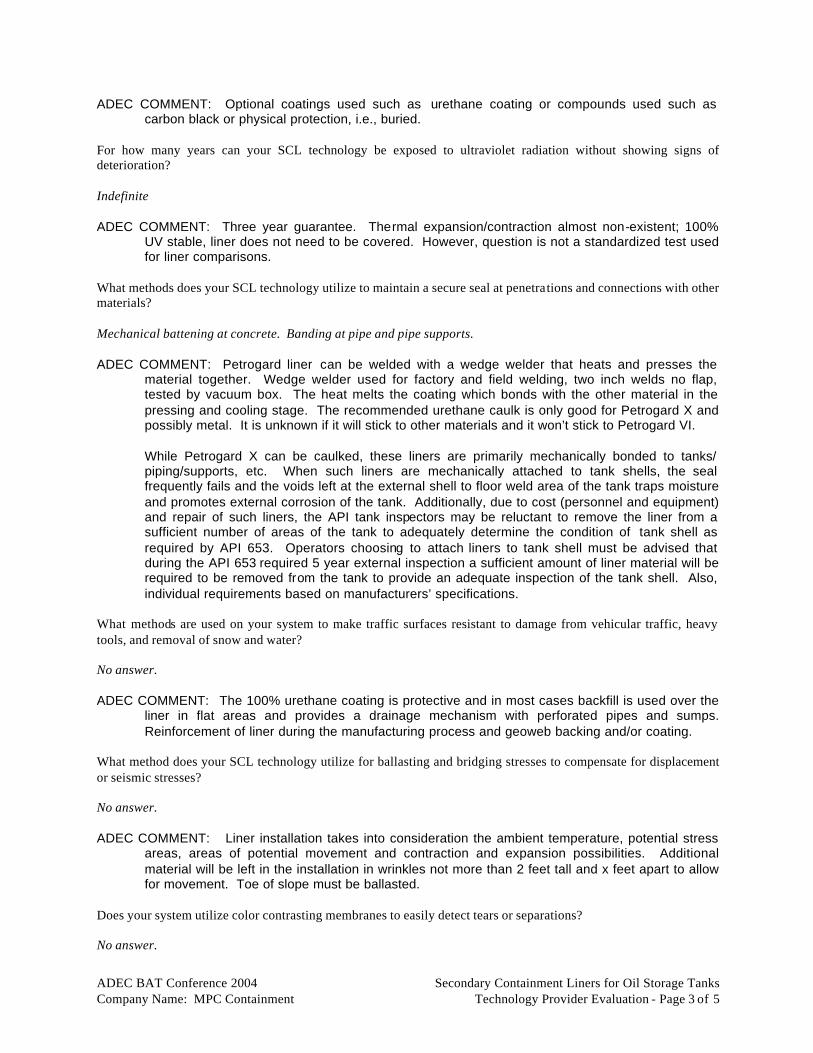
ADEC BAT Conference 2004 Secondary Containment Liners for Oil Storage Tanks Company Name: MPC Containment Technology Provider Evaluation - Page 3 of 5
ADEC COMMENT: Optional coatings used such as urethane coating or compounds used such as carbon black or physical protection, i.e., buried.
For how many years can your SCL technology be exposed to ultraviolet radiation without showing signs of deterioration? Indefinite ADEC COMMENT: Three year guarantee. Thermal expansion/contraction almost non-existent; 100%
UV stable, liner does not need to be covered. However, question is not a standardized test used for liner comparisons.
What methods does your SCL technology utilize to maintain a secure seal at penetrations and connections with other materials? Mechanical battening at concrete. Banding at pipe and pipe supports. ADEC COMMENT: Petrogard liner can be welded with a wedge welder that heats and presses the
material together. Wedge welder used for factory and field welding, two inch welds no flap, tested by vacuum box. The heat melts the coating which bonds with the other material in the pressing and cooling stage. The recommended urethane caulk is only good for Petrogard X and possibly metal. It is unknown if it will stick to other materials and it won’t stick to Petrogard VI.
While Petrogard X can be caulked, these liners are primarily mechanically bonded to tanks/
piping/supports, etc. When such liners are mechanically attached to tank shells, the seal frequently fails and the voids left at the external shell to floor weld area of the tank traps moisture and promotes external corrosion of the tank. Additionally, due to cost (personnel and equipment) and repair of such liners, the API tank inspectors may be reluctant to remove the liner from a sufficient number of areas of the tank to adequately determine the condition of tank shell as required by API 653. Operators choosing to attach liners to tank shell must be advised that during the API 653 required 5 year external inspection a sufficient amount of liner material will be required to be removed from the tank to provide an adequate inspection of the tank shell. Also, individual requirements based on manufacturers’ specifications.
What methods are used on your system to make traffic surfaces resistant to damage from vehicular traffic, heavy tools, and removal of snow and water? No answer. ADEC COMMENT: The 100% urethane coating is protective and in most cases backfill is used over the
liner in flat areas and provides a drainage mechanism with perforated pipes and sumps. Reinforcement of liner during the manufacturing process and geoweb backing and/or coating.
What method does your SCL technology utilize for ballasting and bridging stresses to compensate for displacement or seismic stresses? No answer. ADEC COMMENT: Liner installation takes into consideration the ambient temperature, potential stress
areas, areas of potential movement and contraction and expansion possibilities. Additional material will be left in the installation in wrinkles not more than 2 feet tall and x feet apart to allow for movement. Toe of slope must be ballasted.
Does your system utilize color contrasting membranes to easily detect tears or separations? No answer.

ADEC BAT Conference 2004 Secondary Containment Liners for Oil Storage Tanks Company Name: MPC Containment Technology Provider Evaluation - Page 4 of 5
ADEC COMMENT: No. What method does your SCL technology utilize for repair of seam separation and can the user make repairs? No answer. ADEC COMMENT: Liner can be repaired with a wedge welder, an automatic welder than clips to the
ends of the liner and welds along the seam. The owner can be trained to operate the welder by a certified Petrogard instructor. Then the operator can conduct repairs while still maintaining the warranty. The welder and training is reasonably priced as to make this an affordable option. Urethane caulking used to connect to penetrations if necessary but mechanical attachment is preferred method. Installation takes into consideration the ambient temperature, potential stress areas, areas of potential movement and contraction and expansion possibilities. Additional material will be left in the installation in wrinkles not more than 2 feet tall and x feet apart to allow for movement. Toe of slope must be ballasted.
4. Cost to implement your SCL technology on Alaska oil storage tanks. What is the per square foot cost (within a rough order magnitude) for the installation of your SCL technology? $1.25 for material. Installation $0.10-1.00/square foot depending on size and complexity. Petrogard VI is half the price of Petrogard X. Welds are made with 2 inches flap, minimizing the extra material needed for the flap. 5. Compatibility with existing operations and technologies in use on existing Alaska oil storage tanks. What are the temperature, tensile strength, permeability, thickness and chemical corrosive characteristics of your SCL technology that make it efficient and cost effective for use on existing Alaska oil storage tanks? Low temperature, high strengths, low permeability, flexibility, long term ease of repair. ADEC COMMENT: Both liners are compatible with crude oil, diesel fuel, fuel oil, gasoline and aviation
gas in 7 day immersion tests. Both liner installation temperature limits are 25-100°F. Both liners hydrostatic resistance are 600 psi. Petrogard VI tensile strength grab is 650/650 lbs and 1” strip lbs is 485/485 lbs. Petrogard X tensile strength grab is 1,100/1,100 lbs and 775/724 lbs. Petrogard VI low temperature is -40°F. Petrogard X low temperature is -50°F. Petrogard VI bursting strength is 950 lbs and for Petrogard X is 1.750 lbs. Petrogard VI puncture resistance is 950 lbs and Petrogard V is 1,750 lbs.
What other type of SCL technology do you recommended as back-up to your SCL technology for use on existing Alaska oil storage tanks? Site monitoring Can your SCL technology be integrity tested with electrical current leak detection systems for liners? Yes, but penetrations cause false positives. Can your SCL technology be integrity tested hydrostatically? Yes, plus electric leak location. The welder welds two seams with a pocket between that are vacuum box tested. 100% of factory and field seams are tested.

ADEC BAT Conference 2004 Secondary Containment Liners for Oil Storage Tanks Company Name: MPC Containment Technology Provider Evaluation - Page 5 of 5
6. Practical feasibility, in terms of engineering and other operational aspects, to implement your SCL technology on Alaska oil storage tanks.
What are the weak points in your SCL technology? No answer. ADEC COMMENT: Welds around penetrations. How can these weak points in your SCL technology be resolved? No answer. ADEC COMMENT: Use of proper welding and adhesion technologies. What foundations or subgrade does your SCL system require? No answer. ADEC COMMENT: Almost any type of subgrade. If any potential for puncture, the vendor recommends
the standard 12 oz/yard geotextile as a barrier between the puncture potential ground and the liner. Vendor provides a site assessment prior to installation. The warranty is based on this site assessment.
7. Environmental impact of your SCL technology must not offset environmental benefits. How will your SCL technology have a positive impact on air quality, land, water quality, and energy requirements? No answer. ADEC COMMENT: No negative environmental impacts to offset environmental benefits. If a generator is
used in the welding process, care must be taken to prevent or contain oil leaks.

APPENDIX G
GSE HIGH DENSITY POLYETHYLENE LINERS BY POLAR SUPPLY COMPANY, INC.

Category 2 – Secondary Containment Liners for Oil Storage Tanks
GSE HDPE Liners (Polar Supply Company) Abstract Best Available Technologies Conference, May 27-28, 2004 Egan Convention Center, Anchorage, AK
GSE HDPE (High Density Polyethylene) Liners (Polar Supply Company)
Steve Gordner
GSE geomembranes are HDPE-welded with carbon black and UV stabilizers. GSE HDPE is highly chemically-resistant and has excellent low temperature properties LAB <-90°C. GSE HDPE liners are used to replace clay or other synthetic liners and have better chemical resistance, better low temperature properties, and lower permeability than other lining systems. The geomembranes can be used in a wide range of applications. Low temperature brittleness is much lower than other widely-used synthetic membranes. Permeability data available demonstrate that permeability of HDPE is lower than other widely used synthetic membranes. Our geomembranes have been used world-wide. Maximum sustained operating temperatures for innocuous environments is 150 degrees Celsius. GSE geomembranes are welded together on site to form a protective barrier should there be a breach. Rolls are 22.5' wide; physical properties meet or exceed those specified in GRI GM15. GSE geomembranes have been installed inside steel and concrete tanks of all dimensions to preserve aging tanks and to protect the tank walls from corrosion. In potable water applications, the geomembrane assures that no ground-water-based contaminants or deteriorating structural containment sediment enters the reservoir. A floating cover or fixed-roof cover can likewise keep unwanted material out of the containment or help confine vapors emitted by the contained liquid.
GSE HDPE geomembranes can be attached to steel tank walls using bolted stainless steel batten strips. Geomembrane can also be attached to concrete foundations using bolted stainless steel batten strips or more economically using GSE PolyLock HDPE concrete embedment attachment strips. The PolyLock strips are attached to the concrete forms prior to pouring. Once the poured concrete has set, the geomembrane can be securely welded to the PolyLock strip to form a continuous attachment. Refer to the GSE Tank Lining application sheet for more specific and technical information. GSE HDPE geomembrane liners are typically utilized for leak detection systems inside the ringwall or retrofit. The liner contains and channels leaked liquids to a leak
detection sump. A GSE drainage geocomposite, placed directly on top of the geomembrane, is typically used to facilitate rapid drainage of any leaked liquid. From small tanks to entire tank farms, the secondary containment area is a critical component of tank lining protection. GSE geomembranes have been proven in hundreds of secondary containment applications. GSE’s trained installation technicians have extensive experience working with pre-existing and complicated piping systems.

ADEC BAT Conference 2004 Secondary Containment Liners for Oil Storage Tanks Company Name: Polar Supply Technology Provider Evaluation - Page 1 of 5
Alaska Department of Environmental Conservation Division of Spill Prevention and Response
Industry Preparedness Program
ADEC Best Available Technology Conference 2004
Secondary Containment Liners for Oil Storage Tanks
Polar Supply, Inc.’s GSE HDPE Evaluation
1. Availability of your SCL technology for oil storage tank operations in Alaska. On how many oil storage tank projects in Alaska has your SCL technology been selected for use? Twelve plus. ADEC COMMENT: Some at Prudhoe Bay. No data on actual containment of spilled petroleum products. On how many oil storage tank projects has your SCL technology been selected for use? Thousands On how many non-oil storage tank projects has your SCL technology been selected for use? Tens of thousands. Five plus in Alaska. ADEC COMMENT: Landfills at Anchorage and Kodiak. Compared to other SCL technologies for conditions similar to those found in Alaska, what elements of your system would allow it to be determined as the best in use for oil storage tank operations in Alaska? Chemical and UV resistant, and longevity, ADEC COMMENT: Liner flexibility (physical property) What procurement specifications, installation requirements, and quality control aspects of your system make it available and applicable in Alaska? No answer. ADEC COMMENT: If there is a spill the HDPE will swell, and if the substance is cleaned up prior to
breach of permeability, the fabric will resume original shape. Textured HDPE will allow adherence to shotcrete. Manufactured from resin.
2. Transferability of your SCL technology to oil storage tank operations in Alaska. What is the permeability of your SCL technology? 1 x 10⁻² cm/sec.

ADEC BAT Conference 2004 Secondary Containment Liners for Oil Storage Tanks Company Name: Polar Supply Technology Provider Evaluation - Page 2 of 5
ADEC COMMENT: Overall evaluations: breakthrough in 6 days or one hour (for gasoline) does not appear to meet the criteria of 18 AAC 75.075 (a)(2)(C) and 18 AAC 75.990(124). Technically, geomembranes are impervious non-porous materials. (Please see Golder Associates report to ADEC dated May 1998, 3.1.1 Permeability and Appendix A 1.1.1.3).
For how many days can your SCL technology contain a North Slope crude oil product without showing signs of deterioration or more than 20% loss of tensile and seam strength? 10 years plus. ADEC COMMENT: However, question posed difficult to answer as it is not a standardized test used for
liner comparisons. ASTM E-96, D-543, D-751 are examples of standardized laboratory tests. For how many days can your SCL technology contain diesel product without showing signs of deterioration or more than 20% loss of tensile and seam strength? 10 years plus, 71 hours. ADEC COMMENT: However, question posed difficult to answer as it is not a standardized test used for
liner comparisons. ASTM E-96, D-543, D-751 are examples of standardized laboratory tests. For how many days can your SCL technology contain gasoline product without showing signs of deterioration or more than 20% loss of tensile and seam strength? 72 hours measurable permeability, 10-16% short term loss of tensile. ADEC COMMENT: Question posed is difficult to answer as it is not a standardized test used for liner
comparisons. See above. 3. Effectiveness or reasonable expectation that your SCL technology will provide increased spill prevention
or other environmental benefits for oil storage tank operations in Alaska. At what temperature does your SCL technology become brittle? 90°F (-15°C) ADEC COMMENT: Difficult to evaluate as question posed is not a standardized test used for liner
comparisons. Refer to ASTM testing values, D-746, D-1790, D-2136. What is the lowest temperature for field welding your SCL technology? 0°F (15°C) What method does your SCL technology utilize for protection from ultraviolet radiation? Carbon Black. ADEC COMMENT: Optional coatings are available. Physical protection such as burying. For how many years can your SCL technology be exposed to ultraviolet radiation without showing signs of deterioration? 30-70 years, depending on latitude.

ADEC BAT Conference 2004 Secondary Containment Liners for Oil Storage Tanks Company Name: Polar Supply Technology Provider Evaluation - Page 3 of 5
What methods does your SCL technology utilize to maintain a secure seal at penetrations and connections with other materials? Mechanical. ADEC COMMENT: Specialized sealing technology. Must be done by a skilled welder. Transition to
another material is not common. For another material, including metal and concrete, installer would use mechanical method for sealing. Would use caulking for added seal. Individual requirements based on manufacturers’ specifications.
What methods are used on your system to make traffic surfaces resistant to damage from vehicular traffic, heavy tools, and removal of snow and water? No answer. ADEC COMMENT: Lay geotech fabric below and above liner. Backfill recommended on flat surfaces. What method does your SCL technology utilize for ballasting and bridging stresses to compensate for displacement or seismic stresses? No answer. ADEC COMMENT: Additional material left in the installation in areas determined to be possible
movement points. Does your system utilize color contrasting membranes to easily detect tears or separations? No answer. ADEC COMMENT: Yes, by request. What method does your SCL technology utilize for repair of seam separation and can the user make repairs? No answer. ADEC COMMENT: Installation and repair must be done with a specialized welder (1 generator and 1
welder). Need skilled welder. Equipment needed is more applicable to larger installations due to cost and size. Not repairable by owner. Would need to hire someone who has daily experience welding HDPE. Extruder and other equipment costs approximately $6,000. Use of heavy equipment to install and conduct repairs, and need for specialized skilled labor, makes this technology inadequate for limited access areas. HDPE requires procedures usually not able to be performed by owner/operator.
4. Cost to implement your SCL technology on Alaska oil storage tanks. What is the per square foot cost (within a rough order magnitude) for the installation of your SCL technology? Highly variable depending on location and project size. Oil tank would probably be $2.00/sf+. ADEC COMMENT: $1-$1.50/sq ft for the material. Installation is the expensive part. More penetrations
results in more cost, possibly as much as $45.00/sf. Welding equipment $2,000-$5,000. Transport adds to cost with each roll of liner (22.5 feet wide) may be up to 4,000 lbs and equipment transport costs. Cheap-product wise. High power requirements for extrusion welder. Takes very good welder and installer personnel. Increased penetrations = increased costs of installation. Best for large jobs (cost of liner will offset high cost of equipment needed for installation).

ADEC BAT Conference 2004 Secondary Containment Liners for Oil Storage Tanks Company Name: Polar Supply Technology Provider Evaluation - Page 4 of 5
5. Compatibility with existing operations and technologies in use on existing Alaska oil storage tanks. What are the temperatures, tensile strength, permeability, thic kness, and chemical corrosive characteristics of your SCL technology that make it efficient and cost-effective for use on existing Alaska oil storage tanks? HDPE has excellent physical properties that make it the most commonly used geomembrane in its type of
application. However, in Alaska project size and location determine cost effectiveness. ADEC COMMENT: Temperatures range is -130°C to 302°C. Liners range from 27-90 mil. Tensile
strength at break ranges from 122-405 lb/in-width. Chemical resistance is limited (liner material may reflect some attack) for benzene, gasoline, oils and grease, kerosene. Chemical resistance is unsatisfactory (liner material is not resistant) for toluene and xylenes. No times noted in chemical resistance. Vendor mentioned breakthrough/permeation with gasoline but crude oil had no effect on permeability. No note of timeframe. Puncture resistance ranges from 59-198 lb. Tear resistance is 21-70 lb, 12-14% elongation before failure.
What other type of SCL technology do you recommended as back-up to your SCL technology for use on existing Alaska oil storage tanks? XR5, Petrogard VI, Petrogard X, Cooley L1023. ADEC COMMENT: Additional liners and liquid/leachate control system. Can your SCL technology be integrity tested with electrical current leak detection systems for liners? Yes. ADEC COMMENT: Yes, by request, some liners can be made completely conductive. A spark plus
tester is used to find leak. The arc is the place of the leak. Can use spark tester only if have conductive sheet installed also.
Can your SCL technology be integrity tested hydrostatically? No answer. ADEC COMMENT: No. In-field testing would include filling welder seam pockets with air. No
requirement for this type of testing. 6. Practical feasibility, in terms of engineering and other operational aspects, to implement your SCL
technology on Alaska oil storage tanks. What are the weak points in your SCL technology? High thermal expansion and contraction, labor intensive, induced wrinkles, large projects 50,000 sf+. ADEC COMMENT: Permeability, chemical resistance, repair issues (skilled welders), size of the welder
and generator, wrinkle problems, high rate of thermal contraction and expansion. There are also concerns for liners that require mechanical connections to tanks/piping/supports/etc., and that require special equipment/personnel to install or repair. When such liners are attached to tank shells the seal frequently fails and the voids left at the external shell to flow weld area of the tank traps moisture and promotes external corrosion of the tank. Additionally, due to cost (personnel and equipment) and difficulty in repairing such liners the API tank inspectors may be reluctant to remove the liner from a sufficient number of areas of the tank to adequately determine the condition of the tank shell as required by API 653. Operators choosing to attach liner to tank

ADEC BAT Conference 2004 Secondary Containment Liners for Oil Storage Tanks Company Name: Polar Supply Technology Provider Evaluation - Page 5 of 5
shells must be advised that during the API 653 required 5 year external inspection, a sufficient amount of liner material must be removed to perform the inspection.
How can these weak points in your SCL technology be resolved? No answer. ADEC COMMENT: Wrinkle problems must be taken into account for installation and repair. It is
important to determine how much extra liner is needed due to thermal expansion and contraction. If there is not enough material, the liner could contract to the point of dislodging piping and valve connections and has been observed lifting up 1 foot of soil. Wrinkles placed on purpose should not fall over on themselves and should be evenly spaced.
What foundations or subgrade does your SCL system require? No answer. ADEC COMMENT: Geotech fabric below liner, or purse sand. Should always use Geotech fabric on
both sides of the liner to protect the liner from punctures. HDPE may require geoweb reinforcement. Best to have prepared grade underneath void of sharps.
7. Environmental impact of your SCL technology must not offset environmental benefits. How will your SCL technology have a positive impact on air quality, land, water quality, and energy requirements? HDPE utilizes a petroleum by-product, has a long viability, and does not break down into harmful chemicals into
the environment. ADEC COMMENT: Potential oil leaks from the generator during installation and repairs. Permeability
and chemical resistance may slow a release, but may still allow the release to enter the environment.

APPENDIX H
NOFI CURRENT BUSTER™ BY ALLMARITIM AS

Category 3 – Fast Water Booming
NOFI Current Buster™ (All Maritim) Abstract Best Available Technologies Conference, May 27-28, 2004 Egan Convention Center, Anchorage, AK
NOFI Current Buster™ (AllMaritim)
Jan Allers
The NOFI Current Buster™ is capable of containing and collecting oil in towing speeds (or currents) up to 3.5 to 4 knots.
The NOFI Current Buster™ (NCB) consists of a Front Sweep (std opening 20m) guiding or herding oil into the Tapered Channel and then into the Separator Tank (holding capacity 30m3) from where the oil is recovered by a simple pump or a conventional skimmer. The NOFI Current Buster is designed to provide the correct methods, techniques, apparatus and training required to assure the safety of personnel, equipment and the environment. Conventional booms will lose oil in towing speeds exceeding +/-1 knots. The NCB contains approximately 70% of the oil in waves at 3.5 knots Fast Water (or towing speed) and more than 90% in calm waters. This represents a dramatic efficiency increase over conventional booms. NCB is presently in use by SERVS and CISPRI; SERVS also operates the world's first NOFI Ocean Buster. This product provides increased opportunities for successful oil containment in areas with high currents (or Fast Waters) and overall efficiency in oil containment operations. Technology does not depend on vessels operating with variable pitch propellers and side thrusters at low long-term towing speeds. NOFI Current Buster is operated as a stand alone unit. SERVS in Alaska did connect some additional guide booms to the Front Sweep during the Windy Bay spill. The NOFI Current Buster can be used in harbors, fjords, high current tides and narrows and outside coastlines.
The NOFI Current Buster has undergone tank testing in oil/waves at Norway, testing at OHMSETT, NJ by the USCG in 1999, and real life usage in Windy Bay diesel spill in PWS in 2001 and the “Rocknes” incident outside Bergen, Norway in January 2004.
The NOFI Current Buster™ (patent pending) is a unique product for containing and recovering oil.
Test in Chena River, Interior Alaska
ADEC BAT Conference 2004 Fast Water Booming Company Name: AllMaritim AS Technology Provider Evaluation - Page 1 of 5
Alaska Department of Environmental Conservation Division of Spill Prevention and Response
Industry Preparedness Program
ADEC Best Available Technology Conference 2004
Fast Water Booming
All Maritim AS’s NOFI Current Buster Evaluation Comments to the manner in which we have responded to the FWB Evaluation sheet: Most likely due to language differences we had some difficulties in interpreting the more precise meaning of some of your questions. Therefore we have clarified our answers by going into details in our replies. While the term FWB relates directly to areas with high currents the benefits of having a system that also in slow waters may be operated in towing speed up to 4 knots are significant. As most oil slicks after a while is long and narrow the effectiveness of a more narrow but 4x speed system may outnumber a wide and slow conventional boom with speed limitation of less than one knot. This limitation reduces the overall efficiency in regard to total area coverage per time unit, operator endurance (it is very demanding to tow at such low speeds over time) and maneuverability (contained oil very often gets lost when a conventional boom is turning and turning at low speed is time consuming). The Current Buster technology improves the area coverage, improves operator efficiency and allows for fast and easy turning – in total the system improves the overall performance also in slow waters. It should also be mentioned that the system is designed, produced and tested at LAT 70 deg. North similar to Prudhoe Bay. 1. Availability of your fast water booming (FWB) technology for containment and recovery of oil in fast
water operations in Alaska. Is your FWB technology available to contingency plan holders in Alaska? Yes. Both the Current Buster (for coastal, inlets, harbours and rivers operations) and Ocean Buster (for high seas offshore, coast and sounds) are on the market and presently used in Alaska by plan holders such as SERVS (presently uses both the Current Buster and the Ocean Buster) and CISPRI (operates one Current Buster). The Harbour Buster (the smallest system) will be available in 2005 and should be especially suitable in rivers and streams as well as harbours and in between islands and skerries. On how many containment and recovery of oil in fast water operations in Alaska has your FWB technology been selected for use? Prince William Sound during the “Windy Bay” spill. This was not a Faster Water response in itself. But the Current Busters has successfully responded and periodically operated in towing speeds exceeding 1 knot. This is therefore an example of a response in slow waters where the system was operating efficiently in towing speeds above the conventional boom systems (as mentioned in Comments) Describe the environments (stream, river, coastal waters, etc.) in which your FWB technology was used in Alaska. The Current Buster has been exercised with in Cook Inlet by CISPRI (which is a fast water area) and it has been tested in a river, i.e., Chena River. In “slow” coastal waters SERVS has exercised since 1999 with a number of Current Busters at 3 to 4 knots towing speed.

ADEC BAT Conference 2004 Fast Water Booming Company Name: AllMaritim AS Technology Provider Evaluation - Page 2 of 5
Please answer the same questions for areas other than Alaska in which your FWB technology has been used. The Current Buster was successfully used in Fast Waters (Vatlestraumen, Norway) during the “Rocknes” heavy fuel oil incident in January 2004. Otherwise the Current Buster has been exercised with in the Amazonas River and tested with Fina Green oil in 5 knots towing speed by the Dutch Coast Guard in Holland. In this instance the system was used as a single ship, side sweep system, i.e., the Current Buster was towed behind an outrigger. 2. Transferability of your FWB technology to containment and recovery of oil in fast water operations
in Alaska. Can your FWB technology be implemented in a stream with a current of greater than or equal to 3 knots? Yes. To benefit from the whole gross storage capacity of approximately 30 tonns (net 10-15tonns) of the Current Buster’s Separator the depth at a given site in the stream should be 8 ft. (It may be assumed that such water depths are found in most streams in Alaska). Since there are no waves in a creek, the system will be effective up to a Current of +4 knots. The Harbour Buster will be very suitable also in streams because of its smaller overall dimensions. Can your FWB technology be implemented in the ocean with rip currents of greater than or equal to 3 knots? Yes, as long as the rip currents in the ocean do not mix the oil into the water column before approaching the system, the Current Buster technology functions well in +3 knots currents. Can your FWB technology be implemented in a river/stream with a current of greater than or equal to 3 knots in the presence of occasional ice floes/pans? In principle the answer is yes. However, it also depends on the “environmental conditions” i.e., how regular and in what sizes the ice floes appear. Reasonable amounts of ice floes of less than 1 sq. ft. will not affect the system. In greater amounts they may be removed “manually” while pumping out the oil. In case of large ice floes the collected oil in the separator storage tank will not be affected but heavy accumulation of ice in the front of the system may lead to a reduced collection efficiency. Mechanically the system is very strong and should handle the ice well. If possible a large mesh (1ft by 1ft) net would be located in front of the sweep. In a large river or sea the tow boats should steer away from larger ice floes. Can your FWB technology be implemented in an off shore environment with a current of greater than or equal to 3 knots? Yes. The Ocean Buster is designed and built for an offshore (high seas) environment. Even if we do not recommend speeds above 4 knots because it is difficult for the towboats to tow the Ocean Buster evenly, the Ocean Buster itself will work up close to 6 knots. Even the smaller Current Buster will be more efficient than most conventional “offshore” booms. 3. Effectiveness of your FWB technology for containment and recovery of oil in fast water operations in
Alaska. Up to what current speed can your FWB technology be implemented and still contain and recover 90% of oil released? Reference is made to tests undertaken with oil at the Ohmsett tank in 1999. The USCG R&D center Final Report dated July 17, 200, “Evaluation of four Oil Spill Recovery Systems in Fast Water Conditions at Ohmsett” lists in Sec. 5.3 a throughput efficiency of 91% at 3,5 knots both for Hydrocal (ca.250 cPs) and Sundex (ca.16000 cPs) oils.

ADEC BAT Conference 2004 Fast Water Booming Company Name: AllMaritim AS Technology Provider Evaluation - Page 3 of 5
Are there differences in effectiveness when your FWB technology is utilized on an Alaska North Slope crude oil as opposed to #2 diesel oil? The system has been tested with a wide range of oils: US Navy tested with Diesel (1.2-6 cPs) . USCG tested w/Suncex at 250 cPs and Sundex at 16,000 cPs, Norwegian Oil Pollution Control Authority, SFT tested with oils at 83, 240; 5,000; 11,300; and 180,000 cPs. The results showed no significant differences in effectiveness. Do you have specific examples or evidence of your FWB technology's performance/effectiveness? The “Windy Bay” diesel spill for which SERVS engaged several Current Bustes is an example from Alaska and which was presented as a success in a paper presented at IOSCE in Vancouver 2003. Even more relevant, however, is the performance of the Current Buster during the “Rocknes” heavy fuel incident which took place in Fast Waters with tidal currents running from 2 to 4 knots. During the regular oil clean-up and especially during the 10 n. miles towing of “Rocknes” from her temporary birth to the CCB base at towing speeds which continuously exceeded 2 knots the Current Buster proved both its capability to contain and control the oil and its high maneuverability. Between 600m and 900m of conventional booms trailed behind the tow and then a single Current Buster. It was a remarkable achievement by the one Current Buster to contain and provide recovery of approximately 20tonns of the heavy fuel oil, being approximately 2/3 of the oil recovered during the 4 to 5 hours towing leg. What is the environmental benefit that will be realized from using your FWB technology? By effectively containing and controlling the oil before reaching the shores or by stopping the oil from exposing the river systems downstream of the spill site the Current Buster will present a significant reduction of the negative consequences of an oil spill both on land, in streams and rivers, or in the seas. 4. Cost to implement your FWB technology for containment and recovery of oil in fast water operations
in Alaska. What is the approximate cost for the purchase of your FWB technology for containment and recovery of oil in Alaska? Without its operating equipment which may range from a tailor made wooden pallet to a 10’ container with a built in boom reel and power pack the cost of a Current Buster is approximately USD 110k. Correspondingly the cost of an Ocean Buster is approximately USD 240k. What level of specialized training is required to operate and maintain your FWB technology? The system is in operation worldwide and the need for specialized training is limited and comparable to the amount of training required for conventional oil booms. Training is normally part of the supply. Is on-site training, including operation and maintenance procedures, included in the cost of your FWB technology system? Yes Are operator manuals included in the cost of your FWB technology system? Yes, as well as a training video. If not, what is the cost of such training and manuals for your FWB technology system? Not applicable

ADEC BAT Conference 2004 Fast Water Booming Company Name: AllMaritim AS Technology Provider Evaluation - Page 4 of 5
5. Compatibility of your FWB technology with existing operations and technologies in use to contain and recover oil in fast waters in Alaska.
Does the use of your FWB technology require a strategic deployment strategy or Tactical Plan for each different geographic location it is to be deployed? A strategic and or tactical plan will benefit the performance of the system but a SOP (Standard Operations Procedure) covering different geographical scenarios and spill situations will also be very effective. How many boats are needed to deploy your FWB technology? To operate the system at sea normally requires two smaller boats while on a river the system just can be anchored. As mentioned previously, it is also possible to tow system behind an outrigger, making the operation a single ship, side sweep. How many people does it take to deploy your FWB technology? As a minimum two persons may deploy the Current Buster but additional hands will speed up the process and make it safer. Does your FWB technology system require continuous personnel support? The system is basically a contingency system not intended for permanent unattended use. However, at sea the system may be anchored overnight and when anchored in a river the system may operate unattended for longer periods. How many people are required to operate your FWB technology system in place after its initial deployment? When towboats are used the minimum required is the towboat crew. Anchored in a river with a smaller spill (than the storage capacity) it may work unattended. 6. Practical feasibility, in terms of engineering and other operational aspects, to implement your FWB
technology to contain and recover oil in fast waters in Alaska. Can your FWB technology be effectively utilized by responders based on the information supplied in operator manuals alone? Yes, but is a great advantage if they have trained with the system before an oil spill. From the time of notification of a spill, what is the minimum amount of time needed to deploy your FWB technology and what method will be utilized? Time: The response time will of course be largely dependant on the quality and scrambling time of the response team, equipment immediately available (trucks, helicopters or shallow draft boats etc) and if the system has been preloaded on the means of transport and to what degree this particular spill situation has been planned and trained. The time will vary between driving/flying time + 20 minutes deployment and installation time up to no immediate response at all (area inaccessible by air due to fog, no access by the river because of waterfalls and similar adverse conditions). Method: The procedure will be to install the equipment near the shore of the stream or directly into shallow part of the stream by either truck or helicopter, inflate it, connect short guidebooms and then pull it out by either a manual or powered winching arrangement or boat, anchor one guideboom to each side of the stream. Then the system is fully operational. Please answer the above using the following factors: The deployment site is a stream with width varying from 30 to 80 feet, is road accessible, and is located 10 miles from your FWB technology? The deployment site is a stream with width varying from 30 to 80 feet, is NOT road accessible, and is located 10 miles from your FWB technology?

ADEC BAT Conference 2004 Fast Water Booming Company Name: AllMaritim AS Technology Provider Evaluation - Page 5 of 5
7. Environmental impact of your FWB technology must not offset environmental benefits. Are there any applications of your technology where its use would offset the environmental benefits? None

APPENDIX I
BOOM VANE BY ORC-AB

Category 3 – Fast Water Booming
Boom Vane (ORC-AB) Abstract Best Available Technologies Conference, May 27-28, 2004 Egan Convention Center, Anchorage, AK
A versatile fast water booming tool, the Boom Vane is used for both recovery and deflection modes of
operation. It is completely self-trimming and requires no attendance once deployed.
Boom Vane (ORC-AB)
Alan Allen of Spiltec, Presenting for ORC-AB
The Boom Vane is a device for oil boom deployment in rivers and other waterways. This powerful yet light response tool allows for rapid boom deployment in fast waters, for spill control and recovery without the use of boats, anchors or fixed installations. The system can be operated in rivers with heavy traffic as the Boom Vane control rudder allows for fast and effortless retrieval from midstream. Overall dimensions & weight: No. 1-wing unit: 1785x310x1012mm = 0.56 m3, 46 kg; #2-float unit: 1400x205x800mm = 0.23 m3, 16 kg - Total: 0.79 m3, 62 kgw. The Boom Vane is constructed as a cascade of vertical wings mounted in a rectangular frame. Powered by the current flow the Boom Vane, held by a single mooring line only, swings out towards the opposite shore with the oil boom in tow. The Boom Vane rides very stable in water speeds ranging from 1 to 5 knots, insensitive to ‘chop’ and fluctuations of the current. Boom lengths for spill recovery range depending on boom specs and deployment site. The Boom Vane system has been used in waters faster than 5 knots, nothing breaks and there's no danger involved. It is designed to start "rising" out of the water in speeds of 5 to 6 knots and when load on system is decreased.
Oil spill response operations are notably difficult in fast water. Considering typical response time margins allowed for river spills in relation to the mobilization time and resources required for conventional boom systems, the BoomVane offers a timely response. It's light, compact, and assembles in minutes without tools. No boat or anchors needed and a complete river system can be transported by a common pick-up. It can be easily carried some distance to the water if no boat landing or direct road access. A boatless river system is comparatively low cost and can be stored near a number of pre-determined sites. After little training a two man team can deploy a 150 meter boom in less than 30 minutes.
The BoomVane is a device for oil boom deployment in rivers and other waterways. Glomma River/Port of Fredrikstad, Norway

ADEC BAT Conference 2004 Fast Water Booming Company Name: ORC-AB Technology Provider Evaluation - Page 1 of 3
Alaska Department of Environmental Conservation Division of Spill Prevention and Response
Industry Preparedness Program
ADEC Best Available Technology Conference 2004
Fast Water Booming Evaluation
ORC-AB’s Boom Vane Evaluation 1. Availability of your fast water booming (FWB) technology for containment and recovery of oil in fast
water operations in Alaska. Is your FWB technology available to contingency plan holders in Alaska? Yes On how many containment and recovery of oil in fast water operations in Alaska has your FWB technology been selected for use? Approximately 5 to date Describe the environments (stream, river, coastal waters, etc.) in which your FWB technology was used in Alaska. Shore-based operations: streams, rivers, estuaries, tidal areas. Vessel-based sweep operations: all navigable waters. Please answer the same questions for areas other than Alaska in which your FWB technology has been used. Total of 104 units sold. 2. Transferability of your FWB technology to containment and recovery of oil in fast water operations
in Alaska. Can your FWB technology be implemented in a stream with a current of greater than or equal to 3 knots? Yes Can your FWB technology be implemented in the ocean with rip currents of greater than or equal to 3 knots? Yes Can your FWB technology be implemented in a river/stream with a current of greater than or equal to 3 knots in the presence of occasional ice floes/pans? Yes Can your FWB technology be implemented in an off shore environment with a current of greater than or equal to 3 knots? As vessel sweep application yes.

ADEC BAT Conference 2004 Fast Water Booming Company Name: ORC-AB Technology Provider Evaluation - Page 2 of 3
3. Effectiveness of your FWB technology for containment and recovery of oil in fast water operations in Alaska.
Up to what current speed can your FWB technology be implemented and still contain and recover 90% of oil released? The BoomVane performs well in 0,5 to 5-6 knots. If the oil boom can 'take it', the BoomVane can. Are there differences in effectiveness when your FWB technology is utilized on an Alaska North Slope crude oil as opposed to #2 diesel oil? Not applicable Do you have specific examples or evidence of your FWB technology's performance/effectiveness? Many - the best being numerous 'official' demos where we launch a large river boom system in less than half an hour, by two men - no boats or anchors. What is the environmental benefit that will be realized from using your FWB technology? Timely spill responses. Improved booming. 4. Cost to implement your FWB technology for containment and recovery of oil in fast water operations
in Alaska. What is the approximate cost for the purchase of your FWB technology for containment and recovery of oil in Alaska? USD $11,000 What level of specialized training is required to operate and maintain your FWB technology? Two-day training session. Is on-site training, including operation and maintenance procedures, included in the cost of your FWB technology system? No - offered on request. Are operator manuals included in the cost of your FWB technology system? Yes If not, what is the cost of such training and manuals for your FWB technology system? USD $1,500 + travel & accommodation costs per training session. 5. Compatibility of your FWB technology with existing operations and technologies in use to contain
and recover oil in fast waters in Alaska. Does the use of your FWB technology require a strategic deployment strategy or Tactical Plan for each different geographic location it is to be deployed? No, but knowledge of response site shortens the deployment time even further.

ADEC BAT Conference 2004 Fast Water Booming Company Name: ORC-AB Technology Provider Evaluation - Page 3 of 3
How many boats are needed to deploy your FWB technology? None. How many people does it take to deploy your FWB technology? Minimum two, ideally three. Does your FWB technology system require continuous personnel support? None. How many people are required to operate your FWB technology system in place after its initial deployment? One 6. Practical feasibility, in terms of engineering and other operational aspects, to implement your FWB
technology to contain and recover oil in fast waters in Alaska. Can your FWB technology be effectively utilized by responders based on the information supplied in operator manuals alone? Yes, given they are handy men with an understanding of moving waters. From the time of notification of a spill, what is the minimum amount of time needed to deploy your FWB technology and what method will be utilized? Trained staff with knowledge of the deployment site can have it in place within half an hour. Please answer the above using the following factors: The deployment site is a stream with width varying from 30 to 80 feet, is road accessible, and is located 10 miles from your FWB technology? Less than an hour. The deployment site is a stream with width varying from 30 to 80 feet, is NOT road accessible, and is located 10 miles from your FWB technology? The equipment can be hand carried (booms dragged); time is a question of terrain and distance. 7. Environmental impact of your FWB technology must not offset environmental benefits. Are there any applications of your technology where its use would offset the environmental benefits? No

APPENDIX J
RIVER CIRCUS BY QUALI TECH ENVIRONMENTAL

Category 3 – Fast Water Booming
River Circus (Quali Tech Environmental) Abstract Best Available Technologies Conference, May 27-28, 2004 Egan Convention Center, Anchorage, AK
River Circus (Quali Tech Environmental)
Mark Ploen
The River Circus is in the simplest terms an artificial lagoon. It is constructed of aluminum and is L 80” x 52.5” x 27”. Water/oil is directed via boom into the circus then rotates around the Circus concentrating the oil on top and discharging the extra water out the bottom. The River Circus is designed for use in rivers with water current speeds of 0.2 – 3.0 Knots (at point of recovery). The Circus works with any type boom. The River Circus is an improvement on small skimmers used in river situations. The River Circus has some distinct advantages in that it allows a more efficient recovery of oil from moving water. The factors that allow the River Circus to operate more efficiently is the fact that you can slow down the surface flow of a river and you can concentrate the volume of oil in the Circus to be recovered. The River Circus can also be set up with many different types of pumps. The river water is directed into the Circus by the boom and the surface water/oil rotates around the circus and the lower water is discharged out the bottom of the Circus. The Circus will increase the efficiency of a river skimming operation, thus getting more oil out of the water faster. The only power required for the Circus is the flow of water. Alaska has many rivers that would be perfect locations for deploying the Circus. It can be used anyplace you are skimming in a river situation as well as in an advancing mode with a vessel. The River Circus is used in Europe and has been tested by the USCG. The River Circus can be used in any river skimming operation to increase the effectiveness of the operation. It also can be used in a vessel sweep mode and will work just as well with an advancing vessel.
River Circus – A fast water oil skimmer recovers floating oil
in rivers, waterways, and other fast water environments.

ADEC BAT Conference 2004 Fast Water Booming Company Name: QualiTech Environmental Technology Provider Evaluation - Page 1 of 3
Alaska Department of Environmental Conservation Division of Spill Prevention and Response
Industry Preparedness Program
ADEC Best Available Technology Conference 2004
Fast Water Booming
QualiTech Environmental’s River Circus Evaluation 1. Availability of your fast water booming (FWB) technology for containment and recovery of oil in fast
water operations in Alaska. Is your FWB technology available to contingency plan holders in Alaska? Yes On how many containment and recovery of oil in fast water operations in Alaska has your FWB technology been selected for use? None Describe the environments (stream, river, coastal waters, etc.) in which your FWB technology was used in Alaska. Not applicable Please answer the same questions for areas other than Alaska in which your FWB technology has been used. Stream and river 2. Transferability of your FWB technology to containment and recovery of oil in fast water operations
in Alaska. Can your FWB technology be implemented in a stream with a current of greater than or equal to 3 knots? Yes Can your FWB technology be implemented in the ocean with rip currents of greater than or equal to 3 knots? Yes Can your FWB technology be implemented in a river/stream with a current of greater than or equal to 3 knots in the presence of occasional ice floes/pans? Yes, when deployed with Boom Vane. Can your FWB technology be implemented in an off shore environment with a current of greater than or equal to 3 knots? Yes

ADEC BAT Conference 2004 Fast Water Booming Company Name: QualiTech Environmental Technology Provider Evaluation - Page 2 of 3
3. Effectiveness of your FWB technology for containment and recovery of oil in fast water operations in Alaska.
Up to what current speed can your FWB technology be implemented and still contain and recover 90% of oil released? 3 knots Are there differences in effectiveness when your FWB technology is utilized on an Alaska North Slope crude oil as opposed to #2 diesel oil? No Do you have specific examples or evidence of your FWB technology's performance/effectiveness? Yes What is the environmental benefit that will be realized from using your FWB technology? Minimize impact 4. Cost to implement your FWB technology for containment and recovery of oil in fast water operations
in Alaska. What is the approximate cost for the purchase of your FWB technology for containment and recovery of oil in Alaska? $12,000 per unit What level of specialized training is required to operate and maintain your FWB technology? None Is on-site training, including operation and maintenance procedures, included in the cost of your FWB technology system? No Are operator manuals included in the cost of your FWB technology system? Yes If not, what is the cost of such training and manuals for your FWB technology system? Not applicable 5. Compatibility of your FWB technology with existing operations and technologies in use to contain
and recover oil in fast waters in Alaska. Does the use of your FWB technology require a strategic deployment strategy or Tactical Plan for each different geographic location it is to be deployed? No

ADEC BAT Conference 2004 Fast Water Booming Company Name: QualiTech Environmental Technology Provider Evaluation - Page 3 of 3
How many boats are needed to deploy your FWB technology? None, when deployed with Boom Vane How many people does it take to deploy your FWB technology? Two Does your FWB technology system require continuous personnel support? No How many people are required to operate your FWB technology system in place after its initial deployment? One 6. Practical feasibility, in terms of engineering and other operational aspects, to implement your FWB
technology to contain and recover oil in fast waters in Alaska. Can your FWB technology be effectively utilized by responders based on the information supplied in operator manuals alone? Yes From the time of notification of a spill, what is the minimum amount of time needed to deploy your FWB technology and what method will be utilized? Immediately Please answer the above using the following factors: The deployment site is a stream with width varying from 30 to 80 feet, is road accessible, and is located 10 miles from your FWB technology? 30 minutes The deployment site is a stream with width varying from 30 to 80 feet, is NOT road accessible, and is located 10 miles from your FWB technology? 30 minutes 7. Environmental impact of your FWB technology must not offset environmental benefits. Are there any applications of your technology where its use would offset the environmental benefits? No

APPENDIX K
WATER STRUCTURES BY GEOCHEM, INC.

Category 3 – Fast Water Booming
Water Structure (GeoChem) Abstract Best Available Technologies Conference, May 27-28, 2004 Egan Convention Center, Anchorage, AK
A Water Structure can contain a localized area of impacted sediments along a shoreline or be utilized as a land boom to prevent oil from entering a water source. Remedial activity can then be scheduled for the impacted site and dewatering the work area can be achieved. Isolation options available are earthen containment dikes or the use of a water containment structure. Minimal disruptions to the ecosystem, protection, and objective management of water resources within the United States have become significant public issues. The Water Structure is a low-impact environmental alternative, which allows for the work area to return to a natural environment as quickly as possible.
A Water Structure will provide a quick cost-effective method for the isolation of a spill or remediation area, eliminating the require-ments for the construction and subsequent removal of earth dikes or dams. Since no backfill or earth will be used to create dikes, no silt or additional sediment will be introduced into the water. The impacted area remains contained
throughout heavy rains or tidal action (site considerations apply). A Water Structure is a viable option for the isolation of a contaminated zone during a spill or remedial activity. Basically, a Water Structure consists of two water-filled membrane “inner” bags with a high strength woven construction fabric as the master “outer” bag that, when filled, acts as a dam or dike that can be positioned wherever needed to contain the oil spill and/or divert the movement of water velocity around the spill. The Water Structure can be fabricated for 1- to 16-feet high and is available in standard lengths of 50, 100 and 200 feet. Custom lengths are available. Once the structure is installed and used to enclose the spill or remediation area, work can be initiated to remove the impacted material from the enclosed work cell. A Water Structure is an effective method for providing containment of and/or diversion around the work area. Specific criteria will require evaluation. Items considered are water velocity, maximum water depth, installation site conditions and climate/spring runoff. Site specifics determine the size and length of a Water Structure. Selection is determined by the height of water to be contained and diverted, streambed slope, water velocity and maximum projected changes in water levels after inflation. Summary A Water Structure is a proven effective system for isolating a contaminated site for remediation efforts and spill control measures. Installation is achieved in a short period of time without significant modifications to the terrain ensuring minimal effect on the ecosystem. A Water Structure is a cost-effective solution when compared to other types of isolation operations. With the quick installation and removal of a Water Structure, on-site time is reduced. Additionally, no additional backfill has to be transported in or out of the area.
Water Structure Cofferdam - Controlling Oil with Water
GeoCHEM, Incorporated
Water Structures (GeoChem)
Water Structure Spill Control and Remediation
Dave Neubauer

ADEC BAT Conference 2004 Fast Water Booming Company Name: GeoChem, Inc. Technology Provider Evaluation - Page 1 of 3
Alaska Department of Environmental Conservation Division of Spill Prevention and Response
Industry Preparedness Program
ADEC Best Available Technology Conference 2004
Fast Water Booming
GeoChem, Inc.’s Water Structures Evaluation 1. Availability of your fast water booming (FWB) technology for containment and recovery of oil in fast
water operations in Alaska. Is your FWB technology available to contingency plan holders in Alaska? Yes, ARCO Alaska has purchased for contingency plan. On how many containment and recovery of oil in fast water operations in Alaska has your FWB technology been selected for use? ARCO Alaska purchased $47,000 worth. Describe the environments (stream, river, coastal waters, etc.) in which your FWB technology was used in Alaska. Possibly in Alaska, but no record of ARCO's use. Please answer the same questions for areas other than Alaska in which your FWB technology has been used. Chevron, CA 2. Transferability of your FWB technology to containment and recovery of oil in fast water operations
in Alaska. Can your FWB technology be implemented in a stream with a current of greater than or equal to 3 knots? Yes Can your FWB technology be implemented in the ocean with rip currents of greater than or equal to 3 knots? Not suitable Can your FWB technology be implemented in a river/stream with a current of greater than or equal to 3 knots in the presence of occasional ice floes/pans? Yes Can your FWB technology be implemented in an off shore environment with a current of greater than or equal to 3 knots? As a platform for staging area.

ADEC BAT Conference 2004 Fast Water Booming Company Name: GeoChem, Inc. Technology Provider Evaluation - Page 2 of 3
3. Effectiveness of your FWB technology for containment and recovery of oil in fast water operations in Alaska.
Up to what current speed can your FWB technology be implemented and still contain and recover 90% of oil released? 100% containment of oil and any velocity of water deflected from impacted area. Are there differences in effectiveness when your FWB technology is utilized on an Alaska North Slope crude oil as opposed to #2 diesel oil? No Do you have specific examples or evidence of your FWB technology's performance/effectiveness? Yes What is the environmental benefit that will be realized from using your FWB technology? Low impact, utilization of onsite materials, i.e., water or oil. 4. Cost to implement your FWB technology for containment and recovery of oil in fast water operations
in Alaska. What is the approximate cost for the purchase of your FWB technology for containment and recovery of oil in Alaska? $6.25/lf - $295.00/lf dependent upon the height of the structure What level of specialized training is required to operate and maintain your FWB technology? On-site training Is on-site training, including operation and maintenance procedures, included in the cost of your FWB technology system? No Are operator manuals included in the cost of your FWB technology system? Yes If not, what is the cost of such training and manuals for your FWB technology system? On-site training - job specific 5. Compati bility of your FWB technology with existing operations and technologies in use to contain
and recover oil in fast waters in Alaska. Does the use of your FWB technology require a strategic deployment strategy or Tactical Plan for each different geographic location it is to be deployed? Yes

ADEC BAT Conference 2004 Fast Water Booming Company Name: GeoChem, Inc. Technology Provider Evaluation - Page 3 of 3
How many boats are needed to deploy your FWB technology? None How many people does it take to deploy your FWB technology? One (1) to five (5) Does your FWB technology system require continuous personnel support? No How many people are required to operate your FWB technology system in place after its initial deployment? One 6. Practical feasibility, in terms of engineering and other operational aspects, to implement your FWB
technology to contain and recover oil in fast waters in Alaska. Can your FWB technology be effectively utilized by responders based on the information supplied in operator manuals alone? No. Not all scenarios have been updated in the user's guide [manual] . From the time of notification of a spill, what is the minimum amount of time needed to deploy your FWB technology and what method will be utilized? Minutes to hours by helicopter. Local water or oil pumped into the structure for deployment and containment of a spill or remediation site or used as portable storage structures to pump the oil directly into the structure itself. Please answer the above using the following factors: The deployment site is a stream with width varying from 30 to 80 feet, is road accessible, and is located 10 miles from your FWB technology? As long as it takes to drive the road with the FWB technology, set it up [size dependent] and deploy the water structure in a matter of an hour or two [size dependent]. US Army Corp of Engineers study was 1.5 hours from setup to finish on a 3' x 100' water structure. The deployment site is a stream with width varying from 30 to 80 feet, is NOT road accessible, and is located 10 miles from your FWB technology? With helicopter from minutes to a hours. Variable size of structure will determine time of deployment. 7. Environmental impact of your FWB technology must not offset environmental benefits. Are there any applications of your technology where its use would offset the environmental benefits? No

APPENDIX L
FOILEX PUMPS BY QUALI TECH ENVIRONMENTAL

Category 4 – Viscous Oil Pumping Systems
Foilex Pumps (Quali Tech Environmental) Abstract Best Available Technologies Conference, May 27-28, 2004 Egan Convention Center, Anchorage, AK
Foilex Pumps (Quali Tech Environmental)
Mark Ploen
The advantages of the Foilex TDS design are many and significant. The casing of the Foilex are stainless steel and is thus more resistant to wear and corrosive environments than the carbon steel pumps. The twin disc design allows for a more efficient pump for viscous liquids due to the fact that our screw can turn at a slower rate for the same output capacity. This is a great advantage with viscous liquids as they have more time to flow into the pump. The TDS 150 OLP will fit into the opening of a standard Butterworth hatch.
The Foilex is very good with viscous liquids and low temperatures will increase the viscosity. The Foilex’s are hydraulically driven and require the following flow and pressure: Twin Disc Screw (TDS) 150 0-16 GPM 2600 PSI, TDS 200 0-26 GPM 2940 PSI, and TDS 250 0-33 GPM 2940 PSI. Foilex TDS pumps are the main component of the Foilex skimmers. They can be purchased as offloading pumps or as skimmers that have the pump as part of the skimmer. The Foilex pumps can be used as transfer pumps or as skimmers any place that transfer pumps and/or skimmers are currently being used. The Foilex pumps are very efficient in the pumping of very viscous liquids and the TDS 150 is one of the only Archimedean screw pumps that will fit through a standard Butterworth hatch. For reduction of pressure drop and pipe resistance, all Foilex TDS Pumps have as an option Annular Injection Flanges for steam, water, or other diluting liquids. Annular Injection Flanges can reduce pressure drop up to 90% under certain conditions. The revolutionary TDS Pump design, with improved capabilities for high viscous oil pumping, has up to 70% higher capacity than any other traditional Archimedean Screw Pump design when compared at
equivalent rpm and screw diameter. The "Twin Disc Screw" Pump has two circular Sealing Discs fitted to each side of the pump screw creating its positive displacement and required pressure when pumping. Each disc operates in an alternating fashion and allows the pump screw diameter to be fully utilized during 2 x 180° of each revolution, thereby facilitating the large and unique displacement of the TDS Pumps.
The "Twin Disc Screw" Pump has two circular Sealing Discs fitted to each side of the pump screw creating its
positive displacement and required pressure when pumping.

ADEC BAT Conference 2004 Viscous Oil Pumping Systems Company Name: QualiTech Environmental Technology Provider Evaluation - Page 1 of 6
Alaska Department of Environmental Conservation Division of Spill Prevention and Response
Industry Preparedness Program
ADEC Best Available Technology Conference 2004
Viscous Oil Pumping Systems
QualiTech Environmental’s Foilex Pump Evaluation 1. Is your VOPS technology the best in use in other similar situations and is it available for use by
Alaska Oil Discharge Prevention and Contingency Plan holders? What is the availability of your VOPS technology in Alaska? SERV's, Seapro and Chaddux have Foilex pumps that could be set up for VOPS. ADEC Comment: The system is available for shipment to Alaska. Is your VOPS technology currently used in Alaska? No ADEC Comment: Yes If yes, where is your VOPS technology being used? No answer ADEC Comment: Chadux, SEAPRO, and SERVS have Foilex pumps. No problems with the systems
were noted. Once on site, what is the minimum amount of time needed to set up your VOPS technology and begin pumping? 30 minutes ADEC Comment: Once on site the system takes about 30 minutes to put into operation. Components of
the systems included pump, power pack and hose. Has your VOPS technology been used in a real event in an Arctic or Sub-Arctic environment? Yes, Russia, Norway, Sweden ADEC Comment: The system has been used in Russia, Norway, and Sweden during spring and summer
conditions (30 to 40 °F). The limiting factor in the system is the hose and hose couplings. If yes, what were the successes and limitations of the operation using your VOPS technology? Did not use injection annular so limitation would have been hose distance.

ADEC BAT Conference 2004 Viscous Oil Pumping Systems Company Name: QualiTech Environmental Technology Provider Evaluation - Page 2 of 6
2. Is your VOPS technology transferable to operations in Alaska? Does the VOPS technology use a method to reduce friction in the discharge hose to improve the ability to pump cold viscous oil? Yes, on inlet or discharge end. ADEC Comment: The system uses injection ports to add water or steam to reduce the frictions and allow
more viscous oils to be pumped. The injection ports can be placed for water on the suction side of the pump. Steam or water for injection can be placed on the discharge side of the pump. Because the tolerance is so close in the pump, steam on the injection side can potentially cause the pump to bind up.
What does your VOPS technology use to lower the shear point during pumping? Lower RPM To what extent does your VOPS technology increase the emulsification of the oil? No answer ADEC Comment: Pump is a positive displacement Archimedes screw pump that operates a low RPM this
combination creates minimal increased emulsification. What can be done to maintain or repair your VOPS technology when it is operating in the field where supplies may be limited or difficult to obtain? Spare cutting knives and spare discs. ADEC Comment: There are few moving parts. Blades and discs are in stock and can be delivered to
most sites in Alaska within 24 hours. Other than structural damage to the pump housing or screw, repairs can usually be repaired in the field. Weak point may be the (polyurethane coated steel) discs, and having two discs increases number of parts that can break.
3. Is there a reasonable expectation that your VOPS technology will provide increased spill prevention
or other environmental benefits? Has your VOPS technology been tested by the Joint Viscous Oil Pumping System (JVOPS) committee for use in viscous oil pumping? No, manufacturer would not participate as they were concerned that the USCG had hired their competitor to run the tests. Have performed their own in Europe. ADEC Comment: No. But the pump was tested in March of 2003 at the viscous oil workshop at the
Center for Marine and then Environmental Safety in Horton, Norway. This is where ice chunks were placed in the bitumen oil to determine how the pump handled ice.
If yes, what were the results of testing of your VOPS technology? No answer What is the maximum viscosity of a liquid that your VOPS technology will pump? 1.3 million cSt +

ADEC BAT Conference 2004 Viscous Oil Pumping Systems Company Name: QualiTech Environmental Technology Provider Evaluation - Page 3 of 6
ADEC Comment: In test conditions the pump was able to move Bitumen at 2 million centistokes with steam injection. The steam, in addition to the water collar, warmed the oil, reducing the actual viscosity to 1.3 million centistokes. The ability to move the oil to the pump is the primary limiting factor on the ability of the pump to move material through it. The hose and couples are the primary discharge limiting factor due to the potential for over-pressurization. One advantage of this pump is the exposed screw which allows for 360° access for oil to enter the screw portion of the pump.
What is the maximum distance your VOPS technology will pump at the maximum viscosity? Not tested ADEC Comment: The system using a 4” hose can lift oil with a viscosity of 200,000 centistokes,
approximately 15 feet. Maximum lift for this system with a hose is 100 feet. Another way of increasing pumping distance is to put another pump in line. This was done during a response in Puerto Rico where the vessel was a half mile of the beach. But there must be good communication between the operators because all systems must be started and shut down at the same time or the results will be parted hose from over pressurizing the system.
What are the pump rates of your VOPS technology for a liquid with viscosity ranges from 25,000 to 200,000 centistokes? No answer ADEC Comment: No information provided during oral presentation. Submission form says that twin disc
design allows for a more efficient pump for viscous liquids since the screw can turn at a slower rate for the same output capacity, allowing more time for viscous liquids to flow to the pump.
What do you do if the base product is too thick to pump with your VOPS technology? Expose the screw portion of the pump. What are the temperature limitations on your VOPS technology for different viscosity oils? None ADEC Comment: This system works better at lower temperature ranges (above freezing). Increasing
temperatures can cause unequal expansion of the metal that will stop or break the pump. What is the maximum lift your VOPS technology can achieve? Not tested What hose specifications are necessary to prevent bursting while pumping with your VOPS technology? High pressure and high pressure fittings. ADEC Comment: No specifics given. However, the hose connection is one of the main weak links in the
system. Modifying the type of hose connector may improve reliability.

ADEC BAT Conference 2004 Viscous Oil Pumping Systems Company Name: QualiTech Environmental Technology Provider Evaluation - Page 4 of 6
What is the physical size of the pump used in your VOPS technology? Three standard versions; one fits through standard Butterworth opening. ADEC Comment: Power pack sizes vary. Pump diameters are TDS 150 >12”; TDS 200 >17”; and TDS
250< 22”. Can your VOPS technology pump fit through a Butterworth opening? Yes, one of three models. ADEC Comment: The smallest (TDS 150) of the three Foilex pumps will operate through Butterworth
opening. What is the capability of your VOPS technology to pump clean product from a tanker to a barge? Works but recommend more efficient clean product pumps. ADEC Comment: The limiting factor is getting the oil to the pump. The 360° exposure of the screw can
help the encounter rate with the oil. What is the capability of your VOPS technology to pump oil emulsion from a barge? Excellent What is the debris handling capability of your VOPS technology? Very good, cutter knives on intake and discharge end. ADEC Comment: Debris in the 2” range can be handled by the system. 4. What is the cost to implement your VOPS technology in Alaska? What is the approximate cost for the installation, maintenance, and repair of your VOPS technology? $20,000 ADEC Comment: Depending on the pump the base pump price ranges from $9,000 to $18,000 without
the float frame. 5. Is your VOPS technology compatible with existing operations and technologies in use in Alaska? Does the VOPS technology interface with existing viscous oil pumping systems currently used in Alaska? Yes, hoses and power packs. Is your VOPS technology compatible with other commonly used components, such as power packs and hose connections, currently used in Alaska? Yes ADEC Comment: This system will work with any PDAS pump in a daisy change configuration.

ADEC BAT Conference 2004 Viscous Oil Pumping Systems Company Name: QualiTech Environmental Technology Provider Evaluation - Page 5 of 6
Can your VOPS technology be repaired with common tools? Yes ADEC Comment: Yes, unless housing is cracked or the screw is broken. 6. Is your VOPS technology practically feasible to implement in Alaska in terms of engineering and
other operational aspects? What are the weak points in your VOPS technology? Not applicable ADEC Comment: The hose and camlocs seem to be the main weak point. The temperature of the oil
also is a factor than can cause problems. If the oil is too hot it can cause the mixed metal pump components to expand unequally, resulting in a shut down and/or damage to the pump. The cutting blade has also been a weak point.
How can these weak points in your VOPS technology be resolved? Not applicable ADEC Comment: Do not over pressurize the hose, consider modification to the hose connections
(vendor did not specify what kind of connection is best). Do not preheat the oil at the intake of the pump with steam injection. Replace cutting blades (field repair).
What power supply does your VOPS technology use? Hydraulic ADEC Comment: 20 to 45 KW hydraulic or diesel power packs Are there alternates to the power system for your VOPS technology? No answer ADEC Comment: System does not need Foilex power pack as long as the alternate power source can
supply the needed KW. Any suitable hydraulic power pack No answer Is steam used in your VOPS technology? Optional, steam or hot water. ADEC Comment: Steam as well as water or other diluted liquid can be injected through flanges on the
pump. Steam must be generated using a separate system. If so, what method is used to generate steam? Any suitable steam cleaner boiler, etc.

ADEC BAT Conference 2004 Viscous Oil Pumping Systems Company Name: QualiTech Environmental Technology Provider Evaluation - Page 6 of 6
7. Do other environmental impacts of your VOPS technology, such as air, land, water pollution, and energy requirements, offset any environmental benefits?
What are the environmental impacts on air, land, and water of your VOPS technology? No answer ADEC Comment: Minimal, proved ample containment exists under the pump to collect potential release
of hydraulic oil. The power packs used to run the pumps will create some air pollution but not significant compared to the overall benefit. The benefits to water and land include lower risk of contamination if a vessel can be successfully offloaded before sinking and would be significant.
What are the energy requirements of your VOPS technology? Varies dependent upon pump model and product viscosity. ADEC Comment: 20 to 45 KW hydraulic power packs.

APPENDIX M
GT-A PUMPS BY LAMOR CORPORATION, LLC

Category 4 – Viscous Oil Pumping Systems
GT-A Pumps (Lamor Corporation) Abstract Best Available Technologies Conference, May 27-28, 2004 Egan Convention Center, Anchorage, AK
Lamor GT-A Positive Displacement Archimedes Screw (PDAS) Pumps (Lamor Corporation)
Jim Mackey
Lamor GT-A 20, GT-A 50 and GT-A 115 Positive Displacement Archimedes Screw Pumps (PDAS) are the most modern and reliable oil spill and salvage pumps available. These portable, hydraulically powered, submersible pumps incorporate new technologies and lessons learned over the last 25 years working with existing technologies. The GT-A pumps are suitable for pumping all fluids including extremely high viscosity oils, emulsions and bitumen. Because of their tight sealing, positive displacement design, they can pump water or extremely high viscosity oil with the same efficiency. The pump capacity is directly proportional to RPM while the maximum discharge pressure can be reached even at very slow speed. The pumps are made in three sizes with capacities 88 GPM, 272 GPM, and 506 GPM and discharge pressure up to 180 psi. The GT-A Pumps are PDAS pumps with improved screw and sealing geometry and updated sealing materials to improve performance. The pumps are fitted with integral Annular Water Injection (AWI) technology on the inlet side of the pump, which allows hot water or steam to be used to increase inflow to the pump while providing water lubrication to reduce pressure in the oil delivery hose. The result is a much wider operating range and a remarkable reduction in discharge pressure. This is covered in depth in JVOPS papers and reports. The GT-A pumps take full advantage of this technology by incorporating it into the pump casing as standard, which reduces overall cost and simplifies the hose arrangements.
These GT-A pumps incorporate many new design features that make them ideal for Alaska conditions to replace older style pumps for salvage offloading, oil skimming systems, tank cleaning, and other transfer operations. The GT-A20, with a capacity of 88 GPM is small and light enough to be carried under one arm and fits into a Butterworth opening (12.5” diameter). This allows access into a wider range of vessel tanks and allows the pump and support equipment to be used in much more remote locations. The pump design is supplied with high torque hydraulic motor and delivers 20% higher discharge pressure than other pumps in its class. The pumps have stainless steel wear plates to protect the aluminum pump housing and plate wheel cover which is not available with other pumps. The GT-A pumps come standard with high temperature seals for use with steam injection and for pumping hot liquids. The Lamor GT-A pump technology allows successful pumping in very cold conditions when oil is at extremely high viscosity or below its pour point. An Alaska example is a vessel grounding like “Kuroshima,” which involved cold fuel oil and where the built-in steam injection technology and high pressure capability would have improved the overall response.
GT-A Pump at JVOPS Test

ADEC BAT Conference 2004 Viscous Oil Pumping Systems Company Name: Lamor Corporation, LLC Technology Provider Evaluation - Page 1 of 5
Alaska Department of Environmental Conservation Division of Spill Prevention and Response
Industry Preparedness Program
ADEC Best Available Technology Conference 2004
Viscous Oil Pumping Systems
Lamor LLC’s GT-A Pump Evaluation 1. Is your VOPS technology the best in use in other similar situations and is it available for use by
Alaska Oil Discharge Prevention and Contingency Plan holders? What is the availability of your VOPS technology in Alaska? 1-2 day, several pumps and support equipment in stock in Cleveland, OH ADEC Comment: The system is available to Alaska oil discharge prevention and contingency plan
holders. Is your VOPS technology currently used in Alaska? (2 ea) GT-A 50 ADEC Comment: Yes, used by the Alyeska Pipeline Company’s Ship Escort and Response Vessel
System. No problems noted. If yes, where is your VOPS technology being used? Alyeska Pipeline Co, Fairbanks Once on site, what is the minimum amount of time needed to set up your VOPS technology and begin pumping? 20 minutes ADEC Comment: Twenty minutes to put into operation once the system is on site. The main
components of the system is the pump, power pack and hoses. Has your VOPS technology been used in a real event in an Arctic or Sub-Arctic environment? Not yet; pumps have been delivered to users in northern regions of US, Finland, and Russia. ADEC Comment: No, this system has not been used in a real event in an Arctic or Sub-Arctic
environment. If yes, what were the successes and limitations of the operation using your VOPS technology? This is a practical and 100% operational system. We expect systems to perform as demonstrated in VOPS workshops.

ADEC BAT Conference 2004 Viscous Oil Pumping Systems Company Name: Lamor Corporation, LLC Technology Provider Evaluation - Page 2 of 5
2. Is your VOPS technology transferable to operations in Alaska? Does the VOPS technology use a method to reduce friction in the discharge hose to improve the ability to pump cold viscous oil? Yes. ADEC Comment: Steam injection at the intake or water injection at the intake and outflow of the pump
can be used to reduce friction. What does your VOPS technology use to lower the shear point during pumping? Hot water inlet injection. To what extent does your VOPS technology increase the emulsification of the oil? Very little. PDAS Pumps impart very little mixing energy to the fluid being pumped and the injection process also does very little mixing. ADEC Comment: Minimal due to type of pump (PDAS) that has a low rpm. What can be done to maintain or repair your VOPS technology when it is operating in the field where supplies may be limited or difficult to obtain? Field repairs are straight forward. Pump rebuild kits are normally supplied with the pumps, which can be serviced with hand tools, basic mechanic skills. ADEC Comment: Most needed repairs are straight forward and do not require specialized tools. Rebuild
kits are included with the system. 3. Is there a reasonable expectation that your VOPS technology will provide increased spill prevention
or other environmental benefits? Has your VOPS technology been tested by the Joint Viscous Oil Pumping System (JVOPS) committee for use in viscous oil pumping? Yes ADEC Comment: Lamor says yes, but we haven’t seen any reports with these particular pumps noted.
In another test the GT-A-50 with annular water injection was visually tested under direction of FlemingCo on bitumen (3 million cSt) with good visual results.
If yes, what were the results of testing of your VOPS technology? Results were presented at BAT; greater than 200 Performance Improvement Factor. What is the maximum viscosity of a liquid that your VOPS technology will pump? >3 million cst ADEC Comment: System has pumped liquids up to 3 million centistokes with water injection, 2 million
centistokes without water injection in tests. What is the maximum distance your VOPS technology will pump at the maximum viscosity? 200 - 300 m depending on oil characteristics; 200,000 cst oil can be pumped approx. 800 meters using 6" hose.

ADEC BAT Conference 2004 Viscous Oil Pumping Systems Company Name: Lamor Corporation, LLC Technology Provider Evaluation - Page 3 of 5
ADEC Comment: Approximately 800 meters using a 6” hose. Additional pumps in a series can also be set up for additional distances. Maximum lift wasn’t provided (or included if it was provided).
What are the pump rates of your VOPS technology for a liquid with viscosity ranges from 25,000 to 200,000 centistokes? 62 m3/hr for GTA 50; 20 m3/hr with GT-A 20; and 115 m3/hr with GT-A 115. ADEC Comment: Depends on pump size: GT-A 20 = 88 gpm with 3” line; GT-A 50 = 88 gpm with 4” line;
GT-A 115 = 506 gpm with a 6” line. Discharge pressure up to 180 psi. The viscosity of the product was not provided with the above information.
What do you do if the base product is too thick to pump with your VOPS technology? Add more local bulk heat What are the temperature limitations on your VOPS technology for different viscosity oils? Approximately 220°F ADEC Comment: The system does not seem to be effected by temperature. The pump has an aluminum
casing with stainless steel inserts and internal parts. What is the maximum lift your VOPS technology can achieve? 20 feet. Pumps are intended to be submerged in product. However, fluid can be lifted nearly 20 feet after priming the pump with water for sealing and cooling. What hose specifications are necessary to prevent bursting while pumping with your VOPS technology? Hose and fittings must be rated for the operating pressure. We supply a 6-inch hose with a working pressure of 150 psi and Hydrasearch split clamp type couplers. The 6" split clamp couplers are rated for 225 psi. ADEC Comment: System comes with 6” hose with a working pressure of 150 psi. Hose connectors are
Hydrasearch split clamp type couplers with 225 psi working pressure. What is the physical size of the pump used in your VOPS technology? No answer ADEC Comment: GT-A 20 = 12” x 8”; GT-A 50 = 16” x 10”; GT-A 115 = 20” x 12”. The power packs vary
in size. Can your VOPS technology pump fit through a Butterworth opening? The GT-A 20 can. ADEC Comment: The smallest pump, GT-A 20, can operate through a Butterworth opening. What is the capability of your VOPS technology to pump clean product from a tanker to a barge? Excellent ADEC Comment: Getting the oil to the pump is the limiting factor, which can be enhanced by using
steam or hot water.

ADEC BAT Conference 2004 Viscous Oil Pumping Systems Company Name: Lamor Corporation, LLC Technology Provider Evaluation - Page 4 of 5
What is the capability of your VOPS technology to pump oil emulsion from a barge? Excellent What is the debris handling capability of your VOPS technology? Excellent ADEC Comment: System has one cutting blade and can handle small (less that 1.95” diameter) debris.
Another advantage to this pump is that it has a check valve. The check valve keeps the oil in the hose from draining back into the source of the oil.
4. What is the cost to implement your VOPS technology in Alaska? What is the approximate cost for the installation, maintenance, and repair of your VOPS technology? Depends on what is available to start. Price for GTA pumps are from $9,000 to $16,000. Need Power Packs, hoses, water pumps and heating systems. Consult with Lamor LLC. ADEC Comment: Costs vary from $9,000 for the small pump to $17,000 for the largest pump. This does
not include hoses, power pack, water pump (for injection) or steam system. 5. Is your VOPS technology compatible with existing operations and technologies in use in Alaska? Does the VOPS technology interface with existing viscous oil pumping systems currently used in Alaska? Yes, existing Power Packs, hoses, etc., can be used. ADEC Comment: Uses standard fittings, therefore can be used with other VOPs. Is your VOPS technology compatible with other commonly used components, such as power packs and hose connections, currently used in Alaska? Yes ADEC Comment: Yes, can use non-Lamor hydraulic power packs. Power needs are 28 to 64 KW. The
pump has a 45° discharge flange for flexibility. Can be used for lightering or with a skimmer. The pump has tight seals to handle water and oil.
Can your VOPS technology be repaired with common tools? Yes ADEC Comment: Yes, for most repairs. Notes: comes with a rebuild kit. 6. Is your VOPS technology practically feasible to implement in Alaska in terms of engineering and
other operational aspects? What are the weak points in your VOPS technology? None ADEC Comment: Hoses may become over pressurized and burst. The weight of the large pump may
also be a limitation. The GT-A 115 weighs 161 lbs.

ADEC BAT Conference 2004 Viscous Oil Pumping Systems Company Name: Lamor Corporation, LLC Technology Provider Evaluation - Page 5 of 5
How can these weak points in your VOPS technology be resolved? Not applicable ADEC Comment: Good communication between operators to keep from over pressurizing the hose. What power supply does your VOPS technology use? Diesel Hydraulic ADEC Comment: 28 to 64 KW hydraulic power packs. Are there alternates to the power system for your VOPS technology? Electro Hydraulic ADEC Comment: Other than Lamor power packs can be used if they can meet the power demands. Is steam used in your VOPS technology? Can be; we suggest the use of very hot water (180 to 210 deg). Steam should condense when in contact with the cold oil. Steam (gas) provides heating but does not provide the lubrication needed in the hoses and is difficult to meter in at a fixed liquid volume rate. ADEC Comment: Steam can be injected at the intake and outflow. The steam generation system is
separate from the VOPs. If so, what method is used to generate steam? Steam Cleaner or Boiler, could use any commercially available source of hot water or steam. 7. Do other environmental impacts of your VOPS technology, such as air, land, water pollution, and
energy requirements, offset any environmental benefits? What are the environmental impacts on air, land, and water of your VOPS technology? None ADEC Comment: Minimal, provided ample containment exists under the pump to collect potential release
of hydraulic oil. The power packs to run pumps will create some air pollution but not significant compared to the overall benefit. The benefits to water and land include lower risk of contamination if a vessel can be successfully offloaded before sinking and would be significant.
What are the energy requirements of your VOPS technology? Diesel fuel for pump operation and heating. ADEC Comment: Depends on chosen system. A 300 psi pump is preferred.

APPENDIX N
ANNULAR WATER INJECTION BY HYDE MARINE, INC.

Category 4 – Viscous Oil Pumping Systems
Annular Water Injection (Hyde Marine) Abstract Best Available Technologies Conference, May 27-28, 2004 Egan Convention Center, Anchorage, AK
Annular Water Injection (Hyde Marine)
Jim Mackey
Annular Water Injection is used to improve inflow to Positive Displacement Archimedes Screw (PDAS) pumps and to create a lubricating sleeve of water between viscous oil and the hose wall. The result is a remarkable reduction in discharge pressure. The flemingCo AWI technology is available for use in cold conditions when oil is below pour point. The AWI technology and operational techniques will allow any PDAS pump to transfer higher viscosity oils than ever before. The performance is well-documented in VOPS tests and workshops during the last five years. These AWI technologies are enhancements to make existing pumps perform up to the level of Best Available Technology, and would be directly transferable to operations in Alaska. Hyde Marine has provided hundreds of Desmi PDAS pumps to responders in Alaska. These pumps are excellent heavy oil pumps but like any mechanical equipment, they have limitations. The AWI technology and techniques allow us to push the operational limits, which is critical in Alaska, where extreme cold, harsh environment and remote locations complicate the response. This technology allows successful pumping in conditions where there would quite likely be failure. A perfect example is the Kuroshima, where this technology would have been very helpful. Hydraulic power packs, hydraulic hose, high pressure discharge hose, steam/water pumps and delivery hose are also required but are normally found in a response inventory. These are available as a complete system if needed. The technology is fully compatible with existing inventory of power packs and hoses. Operating the lubricating water pump system during oil transfer operation adds some complexity to the overall operation but the benefits far outweigh the costs. This technology allows oil to be pumped that would otherwise not be pumpable. The power packs to run pumps will create some air pollution but not significant compared to the overall benefit. Obvious benefits to water and land will be lower risk of contamination if a vessel can be successfully offloaded before sinking.
Internal view of annular water injection flange in operation
Testing in progress, MMS OHMSETT employee (foreground) records system pressure as ESSM and USCG Personnel (background) operate and record
system flow rate and hydraulic controls while pumping oil with ESSM pump systems. Ohmsett, NJ, March 2000.

ADEC BAT Conference 2004 Viscous Oil Pumping Systems Company Name: Hyde Marine, Inc. Technology Provider Evaluation - Page 1 of 5
Alaska Department of Environmental Conservation Division of Spill Prevention and Response
Industry Preparedness Program
ADEC Best Available Technology Conference 2004
Viscous Oil Pumping Systems
Hyde Marine’s Annular Water Injection (AWI) Evaluation 1. Is your VOPS technology the best in use in other similar situations and is it available for use by
Alaska Oil Discharge Prevention and Contingency Plan holders? What is the availability of your VOPS technology in Alaska? The system is available in Alaska. Is your VOPS technology currently used in Alaska? Yes. If yes, where is your VOPS technology being used? SERVS, Seapro, Chadux, Alyeska, and CISPRI have used AWI technology Once on site, what is the minimum amount of time needed to set up your VO PS technology and begin pumping? No answer Has your VOPS technology been used in a real event in an Arctic or Sub-Arctic environment? Yes, HydeMarine has provided hundreds of Desmi PDAS pumps to responders in Alaska. If yes, what were the successes and limitations of the operation using your VOPS technology? These pumps are excellent heavy oil pumps but like any mechanical equipment, they have limitations. The AWI technology and techniques allow us to push the operational limits, which is critical in Alaska, where extreme cold, harsh environments and remote locations complicate the responses. 2. Is your VOPS technology transferable to operations in Alaska? Yes Does the VOPS technology use a method to reduce friction in the discharge hose to improve the ability to pump cold viscous oil? Yes, inlet side annulus ring steam/hot water injection is an option to bulk heating, which does not require that other than the pump itself is being used, fitted with an injection flange on its intake. This is a more portable and compact solution, which besides the hydraulic power lines, only require hook-up to a steam source like a standard mobile steam cleaner. The injected steam heats up the pump intake and gradually the entire pump, thus heating up the oil near the pump and creating almost similar conditions as for local bulk heating. The used steam condenses to hot water via a circular slot injected to the inside of the pump where it has two functions:

ADEC BAT Conference 2004 Viscous Oil Pumping Systems Company Name: Hyde Marine, Inc. Technology Provider Evaluation - Page 2 of 5
1. It heats up the inner surfaces, including moving parts, so that oil touching the surfaces, locally, in a very thin layer, gets heated up. This reduces the viscosity of the thin oil layer, significantly reducing friction inside the pump.
2. Friction is further reduced by the lubricating effect of the injected hot water, which in turn also lubricates the discharge line and facilities the overall transfer of the oil.
What does your VOPS technology use to lower the shear point during pumping? No answer To what extent does your VOPS technology increase the emulsification of the oil? Water injection techniques enable the PDAS pumps to transfer even the most extreme viscosity oils and emulsions at operational pumping rates over operational distances. The PDAS pumps will, in principle for each revolution, cut a segment of “thread” out of the pumped product and push it through the pump. There would still be stripes after pump, no mixing, no emulsification. What can be done to maintain or repair your VOPS technology when it is operating in the field where supplies may be limited or difficult to obtain? No answer 3. Is there a reasonable expectation that your VOPS technology will provide increased spill prevention
or other environmental benefits? Yes. The AWI technology is available for use in cold conditions when oil is below pour point and will allow any PDAS pump to transfer higher viscosity oils than ever before possible. Has your VOPS technology been tested by the Joint Viscous Oil Pumping System (JVOPS) committee for use in viscous oil pumping? Yes, JVOPs test results documented the performance of flemingCo inlet flange on a DOP-250 pump, both of which were provided by HydeMarine. If yes, what were the results of testing of your VOPS technology? The performance of the AWI technology is well-documented in VOPs tests and workshops during the past 5 years. What is the maximum viscosity of a liquid that your VOPS technology will pump? Good performance on heavy oil is what the pumps are famous for. A relatively small portion of the pump power is used for sliding, squeezing, and attempting to compress the oil, which is very power-demanding on higher viscosity oil. This leaves more for the task to move the product forward, or, in other terms, the pumps have an overall high efficiency on high viscosity oil. What is the maximum distance your VOPS technology will pump at the maximum viscosity? Despite the good performance on heavy oil, the PDAS pump will be severely challenged on extreme viscosity oil, i.e., bitumen or very cold heavy oil (consider that the viscosity may be in the 500,000 to more than 3 million cSt range). The oil will not freely flow into the pump and even if it does get into the pump, the friction inside the pump and in the discharge line may be more than the pump can handle without causing damage to itself, its hydraulic motor, or the discharge hose. Therefore, in such situations, it is necessary to use a flow-enhancing technique to pump the product over an operation distances at an operational rate.

ADEC BAT Conference 2004 Viscous Oil Pumping Systems Company Name: Hyde Marine, Inc. Technology Provider Evaluation - Page 3 of 5
The most important USCG discharge side water lubrication test result have been a impressive factor 10 to 12 reduction in pressure drop, while pumping oils over long distances at viscosities not exceeding 50,000 cSt with a DOP-250 PDAS pump. What are the pump rates of your VOPS technology for a liquid with viscosity ranges from 25,000 to 200,000 centistokes? At a test at DESMI’s test facility in Aalborg, Denmark, cold bitumen, with a bulk temperature of 14-15°C (>3 million cSt) was transferred using a DOP-250 Pump equipped with a flemingCo inlet side steam/hot water injection system, pumped through 6 feet of hose at a rate of 198 gpm. What do you do if the base product is too thick to pump with your VOPS technology? Use a flow-enhancing technique as described above. What are the temperature limitations on your VOPS technology for different viscosity oils? The PDAS pumps are excellent heavy oil pumps, and the AWI technology and techniques allow us to push the operational limits. What is the maximum lift your VOPS technology can achieve? DOP/DS-250* 165 pounds, Max. Pressure 10 bar/147 psi, Maximum standard capacity 100 m3h/440 USGPM @
800 RPM, optional capacity would be 125 m3h @ 1,000 RPM (with lower torque motor) DOP-250 Dual* 176 pounds, Max. Pressure 10 bar/147 psi, Maximum standard capacity 100 m3h/440 USGPM @
800 RPM, optional capacity would be 125 m3h @ 1,000 RPM (with lower torque motor) DOP-160 68 pounds, Max. Pressure 10 bar/147 psi, Maximum standard capacity 30 m3h/132 USGPM @
1,000 RPM * These pumps will require higher torque/lower RPM motor on very high or extreme viscosity oil. What hose specifications are necessary to prevent bursting while pumping with your VOPS technology? No answer What is the physical size of the pump used in your VOPS technology? See above. All PDAS pumps are made for mobile use and especially the smaller pumps offer the important combination of portability and heavy oil performance. Can your VOPS technology pump fit through a Butterworth opening? No answer What is the capability of your VOPS technology to pump clean product from a tanker to a barge? No answer What is the capability of your VOPS technology to pump oil emulsion from a barge? No answer What is the debris handling capability of your VOPS technology? No answer

ADEC BAT Conference 2004 Viscous Oil Pumping Systems Company Name: Hyde Marine, Inc. Technology Provider Evaluation - Page 4 of 5
All four pumps have cutting knife systems, which chop lots of the debris that could seize the operation for many other pump types. The open structure plays an important role when the chopped debris must be brought forward through the pump. 4. What is the cost to implement your VOPS technology in Alaska? What is the approximate cost for the installation, maintenance, and repair of your VOPS technology? Budget pricing for the inlet-side flemingCo AWI flange is $2,500, discharge side flange for 6” pump is a bit less. 5. Is your VOPS technology compatible with existing operations and technologies in use in Alaska? Does the VOPS technology interface with existing viscous oil pumping systems currently used in Alaska? Yes. Is your VOPS technology compatible with other commonly used components, such as power packs and hose connections, currently used in Alaska? Fully compatible with existing inventory of power packs and hoses. Operating the lubricating water pump system during oil transfer operation adds some complexity to the overall operation but the benefits far outweigh the costs. Can your VOPS technology be repaired with common tools? No answer 6. Is your VOPS technology practically feasible to implement in Alaska in terms of engineering and
other operational aspects? Yes, it is currently being used in Alaska. What are the weak points in your VOPS technology? Severely challenged on extreme viscosity oil, like bitumen or very cold heavy oil. How can these weak points in your VOPS technology be resolved? It is resolved using a flow-enhancing technique as described above. What power supply does your VOPS technology use? No answer Are there alternates to the power system for your VOPS technology? No answer Is steam used in your VOPS technology? No answer If so, what method is used to generate steam? No answer

ADEC BAT Conference 2004 Viscous Oil Pumping Systems Company Name: Hyde Marine, Inc. Technology Provider Evaluation - Page 5 of 5
7. Do other environmental impacts of your VOPS technology, such as air, land, water pollution, and energy requirements, offset any environmental benefits?
What are the environmental impacts on air, land, and water of your VOPS technology? The power packs to run pumps will create some air pollution but not significant compared to the overall benefit. Obvious benefits to water and land will be lower risk of contamination i f a vessel can be successfully offloaded before sinking. What are the energy requirements of your VOPS technology? No answer

APPENDIX O
ABRASIVE JET CUTTER BY BOOTS & COOTS

Category 6 – Source Control Technology
Abrasive Jet Cutter (Boots & Coots) Abstract Best Available Technologies Conference, May 27-28, 2004 Egan Convention Center, Anchorage, AK
Abrasive Jet Cutter (Boots & Coots)
Halliburton External Abrasive Jet Cutter, Presenting for Boots & Coots
Terry Edwards
The Halliburton external Abrasive Jet Cutter is technology that was developed in 1991 for the well fires in Kuwait following Operation Desert Storm. The task put forth for the development of the jet cutter was that it had to be an external, easy to rig up, self-contained mobile power unit and had to be able to cut a well head off while the well was burning. The external Abrasive Jet Cutter was born and has been credited with greatly reducing the amount of time spent capping the burning oil fields of Kuwait. An advantage of this new technology is that it allows a firefighting capping team to cap a well on fire, thus greatly reducing the amount of time required to be in close proximity to the burning well. What does this translate to? Decreased environmental damage to the surrounding area, less hydrocarbons lost to the atmosphere, and monetary savings to the customer. How does this technology work? The external abrasive jet cutter is positioned into a burning well utilizing an Athey Wagon and a bull dozer. The cutter is basically two units when assembled: the cutter and hydraulic power pack. The cutter consists of two opposing nozzles each tracked in a rectilinear direction; each of the nozzles is responsible for cutting half the well head assembly or casing strings. Abrasive slurry is pumped through the tungsten carbide nozzles at a rate of 168 gallons per minute and at a pressure of 10,000 pounds per square inch. Once good slurry is traveling through the nozzles, the remotely located hydraulic power pack is activated to start the process of cutting the well head. The external abrasive jet cutter is designed to cut the well on fire. To accomplish this task, all hydraulic hoses are encased in a water protective jacket that can withstand temperatures in excess of 2500 degrees Fahrenheit. After the wellhead has been cut off, the fire will be vertical allowing the firefighting capping crew to do their part in containing the blowout.
Cutter Clear View
ADEC BAT Conference 2004 Well Capping Company Name: Boots & Coots Technology Provider Evaluation - Page 1 of 4
Alaska Department of Environmental Conservation Division of Spill Prevention and Response
Industry Preparedness Program
ADEC Best Available Technology Conference 2004
Well Capping Evaluation Sheet
Boots & Coots’ External Abrasive Jet Cutter Evaluation 1. Availability of your well capping (WC) technology in Alaska. Upon notice to proceed, assuming that an Athey wagon and a D-8 dozer are at the well site, how much time will you need to initiate your WC technology at the wellhead? Two days ADEC Comment: Within about 24 hours. Jet cutter is generally not required until Day 2 or 3 of the event; Fire Department orders the equipment. Some equipment is already in Alaska (on North Slope). 2. Transferability of your WC technology to well capping operations in Alaska. What is the coldest temperature that your WC technology can be implemented on well capping operations? Arctic conditions ADEC Comment: Temperature is not a limitation; can be used in Arctic conditions. How much water is required to imple ment your WC technology? 500 BBL or 21,000 gallons ADEC Comment: 160 gallons/minute. About 500 barrels total is required (equivalent to the capacity of one Frac tank). Water must be about 50 to 60°F. Where would the water to implement your WC technology come from? Heated Frac Tank ADEC Comment: Fresh or salt water can be used. Can your WC technology be implemented at blowouts at an offshore platform or on a Mobile Offshore Drilling Unit? Yes Can your WC technology be implemented at blowouts onshore? Yes

ADEC BAT Conference 2004 Well Capping Company Name: Boots & Coots Technology Provider Evaluation - Page 2 of 4
Can your WC technology be implemented at blowouts on ice islands? Yes What are the specific conditions under which your WC technology can be successfully implemented on well capping operations for an ignited well? Designed to cut on fire ADEC Comment: Jet cutter can be used on either gas or oil well; any size well at any pressure. The 900 flange works with any Athey wagon. Sufficient space is required around the well. What are the support and logistic requirements necessary to get your WC technology on site for implementation on well capping operations? Air freight to Alaska ADEC Comment: The jet cutter is shipped in a self-contained package with spare parts. Packaged unit weights 8,000 pounds. Can be transported by helicopter (heavy lift required), barge, air freight, rolligon. Packaged jet cutter measures 6x4x4. The Boots & Coots container on the North Slope has everything that might be required for the jet cutter to be effective. 3. Effectiveness of your WC technology for well capping operations in Alaska. How will your WC technology provide increased spill prevention or other environmental benefits? Allows you to cut well on fire ADEC Comment: Cuts well off in one hour rather than multiple days. Reduces the discharge volume 4. Cost to implement your WC technology for well capping operations in Alaska. What are the ranges of costs you have charged to use your WC technology to remove a damaged wellhead and install a well capping stack? $30,000+/Daily for jet cutter, this is excluding horsepower. ADEC Comment: $90,000 per well cut. Blowout costs greater than $500,000/day, not including the cost of environmental damage and cleanup. 5. Compatibility of your WC technology with existing exploration and/or production operations and
technologies in use to cap wells in Alaska located both on-shore and off-shore, and in remote locations (cannot be accessed by vehicle).
Is the power supply required for your WC technology available on site? Self contained power pack hydraulic unit ADEC Comment: Power supply in self-contained package. If not, is it transported with your WC technology? N/A ADEC Comment: Power supply in self-contained package.

ADEC BAT Conference 2004 Well Capping Company Name: Boots & Coots Technology Provider Evaluation - Page 3 of 4
How will you reconcile your safety policy for using your WC technology with those of the facility operator? Already in place with the North Slope Well Control Alliance ADEC Comment: Jet cutter does not require workers to be close to the well. What additional resources does your WC technology use for removal of the damaged wellhead and installation of the well capping stack? 20/40 Frac sand, Athey Wagon and D-8 Bull dozer ADEC Comment: Athey wagon, frac tank. What are the logistical requirements for your additional resources to use your WC technology? Sand is available in Alaska at Halliburton ADEC Comment: Space constraints. Are these additional resources to use your WC technology readily available in Alaska? Yes ADEC Comment: Yes, except for heavy lift helicopters. What modifications to existing operations/equipment would be required in order to implement your WC technology? None ADEC Comment: No noteworthy modifications are required. Frac tanks must be insulated. What resources would be required of the facility operator in order to implement your WC technology? Request of equipment and transportation ADEC Comment: Sufficient space around the wellhead; high pressure pumping equipment, logistical support. How would you provide heat-shielding/protection for equipment and personnel using your WC technology? Firesleeve or siltemp thermal sheeting material. ADEC Comment: Fire sleeve protection on the Athey wagon arm. 6. Practical feasibility of your WC technology, in terms of engineering and other operational aspects,
for implementation on well capping operations. On how many well capping operations has your WC technology been selected for use? 250+ ADEC Comment: More than 250 in Kuwait alone.

ADEC BAT Conference 2004 Well Capping Company Name: Boots & Coots Technology Provider Evaluation - Page 4 of 4
On how many drilling operations has your WC technology be selected for use (pre-planning)? Alaska, plus Boots & Coots Well Sure Program, 400 yearly. ADEC Comment: 400 annually. What are the limitations of your WC technology? Not designed to cut under water ADEC Comment: Any size well, any pressure. However, cannot be used underwater or if wellhead is “cratered.” What specialized training is required to implement your WC technology? On-going training, each job/wellsite is different. How long does it take to train personnel to use your WC technology? On-going Do you provide the trained personnel to use your WC technology? Yes ADEC Comment: Yes, Boots & Coots personnel operate the jet cutter. 7. The environmental impact of your WC technology must not offset environmental benefits. Is there a negative impact on air quality, land, water quality, and energy requirements when using your WC technology? No ADEC Comment: No negative impact.

APPENDIX P
VOLUNTARY WELL IGNITION AND CAPPING WHILE BURNING BY BOOTS & COOTS

Category 6 – Source Control Technology
Voluntary Well Ignition and Capping While Burning (Boots & Coots) Abstract Best Available Technologies Conference, May 27-28, 2004 Egan Convention Center, Anchorage, AK
Voluntary Well Ignition and Capping While Burning (Boots & Coots)
Larry Flak Often when you can’t control a well blowout and are unable to contain the spill, voluntary
ignition is your only option. Once a blowout occurs in the well and the fire is under control, smoke isn’t the issue. Part of the strategy of voluntary ignition is how you approach the well and how you physically ignite it. Recently, a blowout occurred in Roland Hills, Mississippi, where a well collapsed while running a completion string and the BOPs failed to seal because of an obstruction. Once the crew realized they couldn’t control the flow, they ignited the well. With the Roland Hills incident an ICS system was implemented, similar to those in the North Slope. Several federal agencies were present; including the EPA, MMS, and the U.S. Coast Guard to monitor the well kill. Mobilization equipment removed the rig and fabrication of heat shelters provided refuge. A lined water pit was used in this location and removal of the rig began. The BOPs were destroyed by the heat and therefore removed. Clearing a path of refuse so that the jet cutter had access took approximately 3 days. Establishing a water supply was essential and on this location a water treatment plant was built so that the water didn’t become an added hazard. In Arctic locations, where water may not be readily available to cool the operation, Boots & Coots rely on galvanized roofing tin, shiny side out, because it is an extremely effective heat reflector and is readily available. Annual drills are conducted on the North Slope to ensure supply availability. It is critical to do as much work dry as you can so that mudholes aren’t created, especially in frozen tundra. The Athey Wagon is used to back the jet cutter up to the well to cut the wellhead and bulldozers are used to knock over the BOPs. A Venturi tube is used over the fires to make it flow vertically, creating a vacuum at the end of the tube to push the fire higher. The crew is able to get closer after the Venturi tubes are installed and make the final cuts. The well capping stack is backed into the fire by a bulldozer and cables are run between the flange on the blowout and the mating flange on the capping stack; this procedure is referred to as “snubbing the flanges.” The crew wears multiple layers of wet cotton. In the Arctic, bunker gear is required and work is conducted under heat shielding.
Access to remote locations is not a problem; airfreight, ice bridges, or barges can be used depending on the time of year. Often equipment already on-hand is used in the well kill operations. Boots & Coots have not experienced a well capping problem they were not able to solve.
Boots & Coots International Well Control, Inc. offers the industry the world’s most experienced well capping company. Most of Boots & Coots personnel trained and worked under well control pioneers, Red Adair, Boots Hansen and Coots Mathews. Boots & Coots has carried on the tradition.

ADEC BAT Conference 2004 Well Capping Company Name: Boots & Coots Technology Provider Evaluation - Page 1 of 4
Alaska Department of Environmental Conservation Division of Spill Prevention and Response
Industry Preparedness Program
ADEC Best Available Technology Conference 2004
Well Capping Evaluation
Boots & Coots’ Voluntary Well Ignition and Capping While Burning Evaluation
1. Availability of your well capping (WC) technology in Alaska. Upon notice to proceed, assuming that an Athey wagon and a D-8 dozer are at the well site, how much time will you need to initiate your WC technology at the wellhead? After debris is cleared, one or two days is "normal." ADEC Comment: One to two days is normal, after debris or facilities are cleared. 2. Transferability of your WC technology to well capping operations in Alaska. What is the coldest temperature that your WC technology can be implemented on well capping operations? There is really no ambient low temp limit, as long as it is safe for personnel to work outside. ADEC Comment: Fire pumps are of little use at -40°F, limited by safety of workers in cold temperatures. How much water is required to implement your WC technology? If the well is on fire, we would use several thousand barrels of water (to keep our personnel cool), if in arctic conditions we would use heat shielding tin. ADEC Comment: Several thousand barrels of water is required. Try to do this as dry as possible. Where would the water to implement your WC technology come from? Normal water sources now available on the slope, land, or ocean water if offshore. ADEC Comment: Salt or fresh water. Can your WC technology be implemented at blowouts at an offshore platform or on a Mobile Offshore Drilling Unit? Yes, with use of support marine vessels such as work boats or barges ADEC Comment: A barge, support vessel, heavy lift transport helicopter, and/or pre-staging selected equipment at an offshore platform or on a Mobile Offshore Drilling Unit are required in offshore environments. Can your WC technology be implemented at blowouts onshore? Yes, and has been used many times successfully, dating as far back of the inception of the well control business (1950's).

ADEC BAT Conference 2004 Well Capping Company Name: Boots & Coots Technology Provider Evaluation - Page 2 of 4
Can your WC technology be implemented at blowouts on ice islands? Yes, same as we would use onshore. ADEC Comment: Same as on shore. What are the specific conditions under which your WC technology can be successfully implemented on well capping operations for an ignited well? This was the function the jet cutter was designed for, and is our preferred and safest capping method to date. ADEC Comment: Site prep work will take 2 to 3 days. What are the support and logistic requirements necessary to get your WC technology on site for implementation on well capping operations? A capping stack normally brought in from Houston (if not locally available) by commercial or charter aircraft or by truck or commercial barge if time allows. ADEC Comment: Varies. This is the most difficult part of the job. 3. Effectiveness of your WC technology for well capping operations in Alaska. How will your WC technology provide increased spill prevention or other environmental benefits? By capping on fire (our preferred method), the volume of unignited hydrocarbons spilled is significantly reduced and thus environmental impact is reduced significantly. ADEC Comment: Limits the volume of oil spilled on land or water. 4. Cost to implement your WC technology for well capping operations in Alaska. What are the ranges of costs you have charged to use your WC technology to remove a damaged wellhead and install a well capping stack? Cost of the capping stack rental, chokes, flow lines, and personnel. This differs greatly from job to job, influenced by many variables, but is a small compared to total blowout costs. ADEC Comment: Variable, depending on location and event. 5. Compatibility of your WC technology with existing exploration and/or production operations and
technologies in use to cap wells in Alaska located both on-shore and off-shore, and in remote locations (cannot be accessed by vehicle).
Is the power supply required for your WC technology available on site? Normally, an Athey Wagon, and D-8 Cat with winch which is available in all Alaska operations. ADEC Comment: Not applicable. If not, is it transported with your WC technology? See above. ADEC Comment: Not applicable.

ADEC BAT Conference 2004 Well Capping Company Name: Boots & Coots Technology Provider Evaluation - Page 3 of 4
How will you reconcile your safety policy for using your WC technology with those of the facility operator? Due to the dangerous nature of our work (in the hot zone) a unique safety policy is published by B & C and furnished and discussed with the operator. ADEC Comment: Only Boots & Coots personnel implement voluntary ignition; they operate under a
unique safety policy. What additional resources does your WC technology use for removal of the damaged wellhead and installation of the well capping stack? Athey Wagon, D-8 Cat with winch, and normal fire pumps (if not in winter arctic conditions), heat shielding material, trained personnel. ADEC Comment: Not applicable. What are the logistical requirements for your additional resources to use your WC technology? Landing strip for commercial or charter, and trucking or helicopter to location. ADEC Comment: Barge or other marine equipment required to support oil field work. Need small
bulldozer and sufficient space to carry out operation. Are these additional resources to use your WC technology readily available in Alaska? Yes ADEC Comment: At present, yes. What modifications to existing operations/equipment would be required in order to implement your WC technology? None ADEC Comment: Debris/facility removal possible. What resources would be required of the facility operator in order to implement your WC technology? We might have to remove some components of existing drilling or production facilities in order to get to the wellhead, but this is normally a part of our job. ADEC Comment: Logistics, tanks, pumps. How would you provide heat-shielding/protection for equipment and personnel using your WC technology? Normally, we use corrugated tin, fabricated on location. ADEC Comment: Heat shelters, galvanized tin roofs, water.

ADEC BAT Conference 2004 Well Capping Company Name: Boots & Coots Technology Provider Evaluation - Page 4 of 4
6. Practical feasibility of your WC technology, in terms of engineering and other operational aspects, for implementation on well capping operations.
On how many well capping operations has your WC technology been selected for use? This technology has been used successfully since the inception of the well control business in the 1950's. ADEC Comment: Many. Technology has been implemented since the 1950’s. On how many drilling operations has your WC technology be selected for use (pre-planning)? Historically most (90%) of the blowouts involve drilling operations. ADEC Comment: Unknown, voluntary well ignition has been proposed in preliminary discussions of the
Point Thomson development in Alaska. What are the limitations of your WC technology? We have to be able to access the wellhead, which is difficult in subsea and especially normal deep water applications. ADEC Comment: Have to be able to access the wellhead. Difficult to implement in deep water
operations. What specialized training is required to implement your WC technology? It takes years of experience. B & C Senior Well Control Specialists have over 200 years of combined experience. ADEC Comment: Not applicable. How long does it take to train personnel to use your WC technology? 5 -10 years depending on the individual. ADEC Comment: Not applicable. Do you provide the trained personnel to use your WC technology? Absolutely. ADEC Comment: Only Boots & Coots personnel implement. 7. The environmental impact of your WC technology must not offset environmental benefits. Is there a negative impact on air quality, land, water quality, and energy requirements when using your WC technology? No, not anywhere near the impact of NOT utilizing these techniques to successfully to cap a well involved in a sustained blowout. ADEC Comment: Impact on air quality depends on the products in the well; impact is minimal compared
to the impact of oil spilled to land or water.

APPENDIX Q
PIPELINE CLAMPS BY PLIDCO

Category 6 – Source Control Technology
Pipeline Clamps (PLIDCO) Abstract Best Available Technologies Conference, May 27-28, 2004 Egan Convention Center, Anchorage, AK
Pipeline Clamps (PLIDCO)
Pipeline Maintenance and Repair Fittings
Pete Haburt
PLIDCO Pipeline Clamps can be designed to special specifications or requirements. All PLIDCO Pipeline Clamps are designed to quickly and safely
repair pipelines, most without shutdown; all to keep downtime to a minimum. PLIDCO Pipeline Clamps have been used worldwide for pipeline repair and maintenance, in a wide variety of applications, both onshore and offshore. Applications include oil, gas, water, chemical, steam, slurry and other piping systems. PLIDCO Pipeline Clamps are designed and manufactured following the applicable codes, and a strict Quality Control program. PLIDCO Pipeline Clamps can be back welded with the line in operation, or bolted-only for weld-hazardous or weld-difficult areas. Factory trained technicians are available to assist you with difficult installations or with measurements for special designs. Since your piping problems cannot wait, PLIDCO factory technicians are on call 24 hours a day, seven days a week to provide you with solutions and technical assistance. PLIDCO Pipeline Clamps have been designed for pressure up to 10,000 psi and temperatures from -250° F to 1100° F.
PLIDCO Spilt + Sleeve
PLIDCO Clamp + Sleeve
PLIDCO Over + Sleeve

ADEC BAT Conference 2004 Pipeline Leak Source Control Technology Company Name: PLIDCO Technology Provider Evaluation - Page 1 of 5
Alaska Department of Environmental Conservation Division of Spill Prevention and Response
Industry Preparedness Program
ADEC Best Available Technology Conference 2004
Pipeline Leak Source Control Technology
PLIDCO’s Pipeline Clamps Evaluation 1. Availability of your pipeline leak SCT to pipeline leaks in Alaska. Following repair of a pipeline using one of your pipeline leak SCT device, how much time will be required to produce an identical device and have it ready for shipment to Alaska as a replacement? In stock to 8 weeks ADEC Comment: 7-10 days for PI materials, longer for larger fittings Where is your SCT currently used? Worldwide ADEC Comment: Worldwide Is your SCT commercially available to Alaska plan holders? Yes ADEC Comment: Yes How many plan holders in Alaska have selected your SCT for use on their regulated pipelines? BP, Phillips, Alyeska, Arco ADEC Comment: Not discussed in depth, common throughout oil patch, included in Alyeska pipeline C
plan. Has your SCT been used on any pipelines in Alaska or in a similar environment? Yes ADEC Comment: Yes, the Plidco Smith+Sleeve clamp has been used on Alyeska TAPs 48” pipeline.
Understood to have been used on smaller diameter pipelines in Alaska as well. If so, please describe its performance. Used on bullet hole 2002 ADEC Comment: The Plidco Smith + Sleeve clamp was not used on Alyeska MP 400 release because of
the high pressure and associated safety issues with its installation. Was used successfully on a lower pressure rupture due to sabotage.

ADEC BAT Conference 2004 Pipeline Leak Source Control Technology Company Name: PLIDCO Technology Provider Evaluation - Page 2 of 5
2. Transferability of your SCT to pipeline leaks in Alaska. What is the range of pipeline diameters your SCT devices are designed to accommodate? 1/2' to 48" ADEC Comment: up to 60” diameter What is the range of pressure ratings your SCT devices are designed to accommodate? 1,000 psi-10K ADEC Comment: up to 10,000 psi What is the maximum size (diameter) puncture in a pipeline that can be sealed using your SCT? 1x pipe diameter Is your SCT designed to control guillotine pipeline breaks? No ADEC Comment: No, although Plidco’s Shear+Plug Clamp can be used to shear and plug a section of
pipe for repair work. What is the maximum pressure a pipeline can be under and can still be sealed using your SCT? 500 psi-2,000 psi; depends on size/length ADEC Comment: Up to 10,000 psi What is the coldest temperature at which your SCT can be implemented on a pipeline? -55°F, requires special materials ADEC Comment: Depending on coatings, gaskets and sealing factors, 3. Effectiveness of your SCT for pipeline leaks in Alaska. Given the size and pressure ranges of your SCT, what is the approximate time for implementation once it arrives on-scene? ½ hr to 6 hrs; depends on size/location. ADEC Comment: Highly variable depending on the size of the pipeline, operating conditions, etc. Is your SCT device appropriate for use as a permanent repair technology on above ground pipe? Yes, must be welded per DOT. ADEC Comment: Yes, some Plidco clamps can be welded into place and serve as permanent repairs.
There is a wide range of clamps offered that can serve difference purposes as needed. Is your SCT device appropriate for use as a permanent repair technology on below-ground pipe? Yes

ADEC BAT Conference 2004 Pipeline Leak Source Control Technology Company Name: PLIDCO Technology Provider Evaluation - Page 3 of 5
ADEC Comment: Yes, same as described above. Will your SCT provide increased spill prevention or other environmental benefits? Can reduce lost product and downtime. ADEC Comment: Not a prevention technology as much as a response tool. However, Plidco sleeves
can be installed to reinforce weakened sections of pipeline, thereby acting as a spill prevention technology. Seal shelf life can range from 2 to 20 years if properly stored and installed.
4. Cost to implement your SCT for pipeline leaks in Alaska. What are the ranges of costs (rough order of magnitude) for the various diameters and pressure ratings of your pipeline leak SCT device? $95 to $150K, depends on size/length/pressure/type. ADEC Comment: Highly variable. Operator must check with Plidco for specific clamp needs. 5. Compati bility of your SCT with existing operations and technologies in use to control pipeline leaks
in Alaska. Does your pipeline leak SCT device require specialized unique equipment to install? Not normally ADEC Comment: No Please identify the equipment your SCT device requires. Pipe surface cleaning equipment, torquing equipment, possibly a crane. ADEC Comment: Heavy equipment commonly available in the oil patch is required. What modifications to existing operations/equipment would be required in order to install your SCT device on a pipeline in Alaska? Remove coatings where seal contacts pipe surface. ADEC Comment: None Is your SCT device transportable by road? Yes ADEC Comment: Yes Is your SCT device transportable by air? Yes ADEC Comment: Yes, subject to availability of suitable aircraft.

ADEC BAT Conference 2004 Pipeline Leak Source Control Technology Company Name: PLIDCO Technology Provider Evaluation - Page 4 of 5
Is your SCT device transportable by boat? Yes ADEC Comment: Yes, subject to availability of suitable watercraft, navigable waters, etc. Identify any logistical limitations for implementation of your SCT devices. Not normally, very large, long, high pressure fittings can be extremely heavy. ADEC Comment: Remote pipeline locations could impact time to transport clamp to repair site and time
to transport required installation equipment. Does use of your SCT device introduce additional safety risks that must be considered prior to application by the plan holder? Hazards of handling and rigging of heavy fittings possible. ADEC Comment: The pipeline and nature of the leak define the risk involved. Plidco clamps do not
introduce additional risks. 6. Practical feasibility of your SCT, in terms of engineering and other operational aspects, for
implementation on pipeline leaks. On how many pipelines has your SCT been selected for use? Thousands over the last 55 years. ADEC Comment: Plidco clamps have been selected for use on pipelines throughout the world for over 50
years. For what range of pipeline diameters has your pipeline leak SCT been selected for use? 1/2" thru 72" ADEC Comment: Up to 60” diameter Has your pipeline leak SCT been involved in any research on methods to seal a hole, puncture or crack in a container or pipe under pressure from the inside out instead of the outside in and what results were observed, if any? No ADEC Comment: Didn’t discuss What specialized training is needed for a responder to use your SCT device to control the pipeline leak? None, DOT OQ for repair fittings. ADEC Comment: Specialized training not required. Plidco has factory representatives available for
consultation, but does not do installation of their clamps. How many trained response personnel are required to effectively install your SCT device? 1 to 4, depends on size etc. ADEC Comment: Highly variable depending on pipeline size, nature of rupture, etc.

ADEC BAT Conference 2004 Pipeline Leak Source Control Technology Company Name: PLIDCO Technology Provider Evaluation - Page 5 of 5
7. The environmental impact of your pipeline leak SCT must not offset environmental benefits. What, if any, negative impacts on air quality, land, water quality or energy requirements might be associated with the use of your SCT? None we are aware of. ADEC Comment: Potential for damage to sensitive land areas (tundra) if heavy equipment needed for
installation must transit off right-of-way pad.

APPENDIX R
WELL BLOWOUT CONTROL BY JOHN WRIGHT COMPANY

Category 6 – Source Control Technology
Well Blowout Control (John Wright) Abstract Best Available Technologies Conference, May 27-28, 2004 Egan Convention Center, Anchorage, AK
Well Blowout and Control (John Wright Company)
Software to assist management of well control hazards; OLGA2000 Well Blowout & Kill Module; and Tools and Procedures for Intersecting Oil Wells
John Wright
Well Control Management - A new software package is being designed to assist operators to manage their well control hazards. The process objectives are divided into four major steps as follows:
• Step 1: Systematic identification of reasonable hazardous incidents. • Step 2: Assessment of the significance of each hazard: What is the impact (considering the incident and recovery) if it occurs, on human safety, the environment, assets,
recovery cost, business disruptions, company reputation. Define current controls to prevent incident occurrence and mitigate escalation based on impact. Define current ability to respond to and recover from the incident. Estimate the probability of the incident occurring and escalating. Define incident risk picture. • Step 3: Implement suitable incident controls to reduce the risk to ALARP: Technology to minimize incident occurrence. Technology to mitigate, respond and recover. Personnel training, drills and certification. Management of information and processes. • Step 4: Process map and software tools to respond to and recover from an incident.
The software is being written in Microsoft.NET. All processes, input/output data and reference documents are stored in a database or hyper-linkable files. Technical toolkits are designed to share common input/output data. Third party software is linkable. All steps include automated report creation in Microsoft Word or Adobe Acrobat minimizing time to complete finished documents. Response process steps include ICS team formations and individual team member responsibilities. OLGA2000 Well Kill Hydraulic Simulation Software – OLGA2000 is the world’s leading multiphase transient software package for simulating oil/gas/water flow in pipelines and wells. Well Flow Dynamics has developed BAT well blowout and well kill modules and associated tool kits designed specifically for modeling well blowouts and kill operations. Accurate blowout simulation is essential in well risk and oil spill modeling and it is paramount in designing kill operations.
This picture illustrates how an underground blowout may occur in a drilling well. Underground blowouts between subsurface intervals are common and can
result in a significant escalation threat if not recognized quickly and controlled correctly.

Category 6 – Source Control Technology
Well Blowout Control (John Wright) Abstract Best Available Technologies Conference, May 27-28, 2004 Egan Convention Center, Anchorage, AK
The hydraulic kill design drives the entire blowout control process from the diagnostics to help determine what is happening; what are the capping loads; should the well be bullheaded or snubbing unit used; how deep do you snub; can you kill off bottom; what tubulars are required; what kill fluid density is needed; what volume; what hydraulic horsepower; what are the trade-offs and sensitivities; what relief well casing design is required; and what kill depth should be targeted. Wrong answers can have catastrophic results, particularly in remote areas where recovery is time consuming and costly. Relief Wells – Tools and procedures have been developed to intersect blowout by drilling a relief well. Other examples include: extending long reach wells offshore to avoid potentially hazardous seabed pipelines or gravel islands; connecting pipelines between platforms or gathering stations to avoid subsea pipelines, running pipelines under canyons; wide river crossing sections with extensive gravel beds on one side; and so forth. Vector Magnetics has developed a unique method BAT for homing-in to intersect wells using a rotating magnet in the bit of the drilling well and a sensor run on wireline in the pre-drilled target well. Procedures have been developed for making the physical connection using expandable casing technology, multilateral connections and pulling a welded or screwed pipeline through depending on the circumstances.

R.1 - Well Control Management by John Wright Company

ADEC BAT Conference 2004 Well Blowout Source Control Technology Company Name: John Wright Company Technology Provider Evaluation - Page 1 of 4 (Well Control Management)
Alaska Department of Environmental Conservation Division of Spill Prevention and Response
Industry Preparedness Program
ADEC Best Available Technology Conference 2004
Well Blowout Source Control Technology
John Wright Company’s Well Control Management Evaluation
1. Availability of your source control technology (SCT) to well blowouts in Alaska. Where and how often has your well blowout SCT been used successfully? We started developing the system 10 years ago. We have used it for operators all over the world to develop risk management, contingency and response plans. Is your well blowout SCT commercially available for plan holders in Alaska? Yes, it is commercially available for plan holders in Alaska. Can your well blowout SCT be staged in Alaska and used by in-state trained responders? Yes it can be staged in Alaska but it will take some effort. We need to find the qualified person(s) to train or transfer or rotate personnel to Alaska to perform the work. It is not a part-time job. If your well blowout SCT is not commercially available and staged in Alaska, what length of time is needed to deploy the equipment and trained responders to Alaska? It would probably take 6 months to 1 year to train a new person who has a petroleum engineering background and 10 years experience. 2. Transferability of your SCT to well blowouts in Alaska. What is the coldest temperature that your well blowout SCT can be implemented? Not applicable How much water is required to implement your well blowout SCT? Not applicable Does your SCT include self-contained water supply units? Not applicable

ADEC BAT Conference 2004 Well Blowout Source Control Technology Company Name: John Wright Company Technology Provider Evaluation - Page 2 of 4 (Well Control Management)
What methods can be successfully implemented with your well blowout SCT to control a surface blowout? Manages response actions. Documents and databases initial actions both at the location and at the office. Develops team organization for tactical and strategic planning. Lists equipment and resource requirements. Provides processes and tools for each team member to accomplish their jobs in the most efficient manner. Tracks and documents progress. Provides meeting schedules and agendas. Provides flowcharts, decision trees, and milestones. What methods can be successfully implemented with your well blowout SCT to control an underground blowout? See above What methods can be successfully implemented with your well blowout SCT to control an offshore blowout? See above What are the specific conditions under which your well blowout SCT can be successfully implemented for an ignited well? System provides procedures to help responders decide when and how to safely ignite a well depending upon its location (onshore, offshore), the flowrates, etc. What are the support and logistic requirements necessary to get your well blowout SCT technology on-site for implementation? Is your well blowout SCT technology equipment transportable by air? Not applicable Is your well blowout SCT technology equipment transportable by road? Not applicable Is your well blowout SCT technology equipment transportable by boat? Not applicable 3. Effectiveness of your SCT for well blowouts in Alaska. How will your well blowout SCT provide increased spill prevention or other environmental benefits? Alaska needs a hazard management system for blowout control. Tens of millions of dollars are being spent yearly to manage oil spill hazards from pipelines and tankers with far less than 1% of that amount dedicated to managing the risk from oil well blowouts. A systematic process to help identify hazards, assess their consequences, identify what controls are in place to prevent and mitigate blowouts, assess the risk picture, determine if the risk should be mitigated further or the well plugged or project cancelled before it is drilled, determine what controls will best mitigate the risk (better training or better design), define response actions for personnel on site and responsible personnel offsite for three incident levels, provide guidelines for initial planning and strategic planning cycles. This system if implemented properly can focus funding on areas that need funding and not every operator buying the same contingency plan over and over. A software system is required to manage and database all these activities. It provides knowledge management in the form of process and resource data bases so responders, managers and public can find specific information that might otherwise be difficult to obtain. Separate databases can be kept, for example 1) Public information; 2) Operator’s Shared Information; 3) Operator’s inhouse information. If properly implemented it should greatly reduce the blowout risk in Alaska.

ADEC BAT Conference 2004 Well Blowout Source Control Technology Company Name: John Wright Company Technology Provider Evaluation - Page 3 of 4 (Well Control Management)
4. Cost to implement your SCT for well blowouts in Alaska. What is range of costs (within a rough order magnitude) for using your SCT to control a blowout? $5,000/day/man for blowout response engineers during a blowout. What is the annual cost to stage your well blowout SCT in Alaska? Will depend on personnel requirements, but 2 persons on a rotation (one in Alaska at a time) from lower 48 would probably cost +/- $500K/year. These persons would not be on standby but developing the Well Control Management System specific to Alaska That is, doing documenting processes, defining resources, making risk assessments, training, writing response plans, defining controls, etc. Does the cost of your well blowout technology include specialized training for responders? Yes Does the cost of your well blowout technology include a trained response crew supplied by your company? 5. Compatibility of your SCT with existing exploration and/or production operations and technologies
in use to control well blowouts in Alaska. What are the power supply requirements for your well blowout SCT? Not applicable Are self-contained power-supply units part of your well blowout SCT? Not applicable Are there safety risks associated with the implementation of your well blowout SCT that must be incorporated into the safety policies of the facility operator? All processes and procedures for well blowout management will need incorporation into the safety policies of the operator. What are the logistical requirements for any additional resources needed to support the use of your well blowout SCT? Typical office space, access to operators who are willing to work to make the system a success. Are the additional resources needed to support the use of your well blowout SCT readily available in Alaska? Yes If additional resources needed to support the use of your well blowout SCT are NOT readily available in Alaska, what is the estimated arrival time in Alaska for any supplementary resources? Additional personnel could be mobilized from other offices as required usually within 24 hours. What modifications to existing operations/equipment would be required in order to implement your well blowout SCT? None

ADEC BAT Conference 2004 Well Blowout Source Control Technology Company Name: John Wright Company Technology Provider Evaluation - Page 4 of 4 (Well Control Management)
What resources would be required of the facility operator in order to implement your well blowout SCT? Time and willingness to share information Does your well blowout SCT have built-in equipment or operational guidelines designed to protect facility equipment and personnel? Yes 6. Practically feasibility of your SCT, in terms of engineering and other operational aspects, for
implementation on well blowout control. On how many well blowout control operations has your SCT been selected for use? We have written more than 300 blowout and related contingency plans and supervised 32 relief well worldwide, including numerous underground blowouts and engineering support for surface capping operations. What new slurries (recipes) have been used since 1995 to cut the time and effort down for well blowout control operations using your SCT? It helps reduce time because response plans have been focused, providing a systematic process for planning all aspects of the control operations. For example; tools and procedures for performing blowout diagnostics, determining blowout flowrates and kill rates; procedures for planning and implementing a relief well offshore in arctic conditions; procedures for implementing a capping operation under arctic conditions; logistic constraints for breakup and freeze up seasons. What prior training is required to use your SCT to control a well blowout on the North Slope or in Cook Inlet? Once procedures are defined training sessions should be held with all key responders both in the office and at the rig site, usually one day. Key personnel such as source control leaders will need more training, perhaps 1 to 2 weeks. Identify any additional limitations of your SCT? Will require significant effort and cooperation to implement for all operators in Alaska. Software is still being developed. 7. The environmental impact of your SCT must not offset environmental benefits. Will your SCT have any negative impacts on air quality, land, or water quality? Not applicable Will your SCT have negative environmental impacts associated with energy requirements for its operation? Not applicable

R.2 – OLGA2000 Well Kill Hydraulic Simulation Software by John Wright Company

ADEC BAT Conference 2004 Well Blowout Source Control Technology Company Name: John Wright Company Technology Provider Evaluation - Page 1 of 4 (OLGA 2000 Well Kill Hydraulic Simulation Software)
Alaska Department of Environmental Conservation Division of Spill Prevention and Response
Industry Preparedness Program
ADEC Best Available Technology Conference 2004
Well Blowout Source Control Technology
John Wright Company’s OLGA 2000 Well Kill Hydraulic Simulation Software Evaluation
1. Availability of your source control technology (SCT) to well blowouts in Alaska. Where and how often has your well blowout SCT been used successfully? It has been used in hundreds of blowout contingency plans and in actual blowouts all over the world since 1989. Is your well blowout SCT commercially available for plan holders in Alaska? Yes ADEC Comment: Yes, the OLGA Well Kill software is commercially available as a service from John
Wright Company. The soft ware is not for sale to operators. The service includes the software and personnel required to perform well blowout simulations either as a planning and preparedness tool or during actual well blowout conditions.
Can your well blowout SCT be staged in Alaska and used by in-state trained responders? It can, but may not be practical depending on demand. If your well blowout SCT is not commercially available and staged in Alaska, what length of time is needed to deploy the equipment and trained responders to Alaska? Many blowout simulations are performed via email and internet. Mobilization can be made generally within 24-48 hours. ADEC Comment: Yes, although it appears the service can be provided largely over the internet and
would be expensive to provide personnel ($4,000 - $10,000 per day). 2. Transferability of your SCT to well blowouts in Alaska. What is the coldest temperature that your well blowout SCT can be implemented? Not applicable How much water is required to implement your well blowout SCT? Not applicable Does your SCT include self-contained water supply units? Not applicable

ADEC BAT Conference 2004 Well Blowout Source Control Technology Company Name: John Wright Company Technology Provider Evaluation - Page 2 of 4 (OLGA 2000 Well Kill Hydraulic Simulation Software)
What methods can be successfully implemented with your well blowout SCT to control a surface blowout? Perform diagnostics, determine blowout rates (oil/gas/water ratios) tune model to product data, evaluate shut-in pressures, should well be capped and bullheaded or diverted for snub kill pressures during snubbing off bottom kills, where to perforate pipe, what mud weight to use, how much volume, what HHP, what rate, for how long. ADEC Comment: Adaptable to manage any blowout scenario. What methods can be successfully implemented with your well blowout SCT to control an underground blowout? See above What methods can be successfully implemented with your well blowout SCT to control an offshore blowout? Perform diagnostics, determine blowout rates, tune model to production data, evaluate shut in pressures, should well be capped and bullheaded or diverted for snub kill pressures during snubbing off bottom kills, where to perforate pipe, what mud weight to use, how much volume, what HHP, what rate, for how long. For relief wells determine pipe sizes, pressure requirements, temperature effects, intersection depth, kill plant requirements, hookups to rig, what type of rig is required, what type of barges are required for holding mud volumes, pumps, etc. What are the specific conditions under which your well blowout SCT can be successfully implemented for an ignited well? Help determine combustion efficiency, evaluate flow rates based on flame height and fluid composition, head radiation. What are the support and logistic requirements necessary to get your well blowout SCT technology on-site for implementation? Need office to work in and access to required input data. Is your well blowout SCT technology equipment transportable by air? Yes Is your well blowout SCT technology equipment transportable by road? Yes Is your well blowout SCT technology equipment transportable by boat? Yes 3. Effectiveness of your SCT for well blowouts in Alaska. How will your well blowout SCT provide increased spill prevention or other environmental benefits? Olga Well Kill is truly BAT for modeling oil/gas and water blowouts. We have 15 years experience in using the software and in modeling blowouts. We are the only company who specialize exclusively in blowout and kill simulations using state of the art technology. ADEC Comment: Increased characterization of risks, ability to provide simulation allows for operators to
develop a better plan to control a well blowout.

ADEC BAT Conference 2004 Well Blowout Source Control Technology Company Name: John Wright Company Technology Provider Evaluation - Page 3 of 4 (OLGA 2000 Well Kill Hydraulic Simulation Software)
4. Cost to implement your SCT for well blowouts in Alaska. What is range of costs (within a rough order magnitude) for using your SCT to control a blowout? $2,000/day/man for non-emergency simulations; $5,000/day/man for blowout emergencies ADEC Comment: Highly variable depending on the size of the field. Literature suggests costs ranging
into millions for actual relief well management and several thousand dollars/day for software simulation work.
What is the annual cost to stage your well blowout SCT in Alaska? Not practical unless demand was high enough to justify full time person in Alaska. If so, the cost of personnel and $2,000/day for simulations (+/- $500k/yr) Does the cost of your well blowout technology include specialized training for responders? Yes Does the cost of your well blowout technology include a trained response crew supplied by your company? Yes ADEC Comment: Cost includes operators for the software, but not actual operations response personnel. 5. Compatibility of your SCT with existing exploration and/or production operations and technologies
in use to control well blowouts in Alaska. What are the power supply requirements for your well blowout SCT? Power to run a laptop Are self-contained power-supply units part of your well blowout SCT? No Are there safety risks associated with the implementation of your well blowout SCT that must be incorporated into the safety policies of the facility operator? No What are the logistical requirements for any additional resources needed to support the use of your well blowout SCT? Office to work out of Are the additional resources needed to support the use of your well blowout SCT readily available in Alaska? Yes If additional resources needed to support the use of your well blowout SCT are NOT readily available in Alaska, what is the estimated arrival time in Alaska for any supplementary resources? 24-48 hrs

ADEC BAT Conference 2004 Well Blowout Source Control Technology Company Name: John Wright Company Technology Provider Evaluation - Page 4 of 4 (OLGA 2000 Well Kill Hydraulic Simulation Software)
What modifications to existing operations/equipment would be required in order to implement your well blowout SCT? None What resources would be required of the facility operator in order to implement your well blowout SCT? Access to petroleum engineer from operator to estimate input data for the simulations. ADEC Comment: Time, software, databases; variable depending on pre-identified resources.
Technology would identify appropriate equipment for the field and anticipated operational requirements to provide source control for the unique well conditions.
Does your well blowout SCT have built-in equipment or operational guidelines designed to protect facility equipment and personnel? No 6. Practically feasibility of your SCT, in terms of engineering and other operational aspects, for
implementation on well blowout control. On how many well blowout control operations has your SCT been selected for use? 50+ ADEC Comment: According to the literature 32 relief well interventions planned and executed including
Steelhead blowout. What new slurries (recipes) have been used since 1995 to cut the time and effort down for well blowout control operations using your SCT? Hydraulic modeling drives every aspect of blowout control operations, from capping to relief wells to underground blowouts. How much mud, what density, how much horsepower, what rate, what size pipe, what depth, what pressures, etc. Without the BAT, operations could be delayed for literally weeks or months due to bad decisions. ADEC Comment: Not discussed What prior training is required to use your SCT to control a well blowout on the North Slope or in Cook Inlet? None, performed by specialists. ADEC Comment: Specialists, not operational responders, perform the simulation functions. Identify any additional limitations of your SCT? It is not for sale, offered only as a service. 7. The environmental impact of your SCT must not offset environmental benefits. Will your SCT have any negative impacts on air quality, land, or water quality? None Will your SCT have negative environmental impacts associated with energy requirements for its operation? None

R.3 - Relief Wells by John Wright Company

ADEC BAT Conference 2004 Well Blowout Source Control Technology Company Name: John Wright Company Technology Provider Evaluation - Page 1 of 4 Relief Wells
Alaska Department of Environmental Conservation Division of Spill Prevention and Response
Industry Preparedness Program
ADEC Best Available Technology Conference 2004
Well Blowout Source Control Technology
John Wright Company’s Relief Wells Evaluation 1. Availability of your source control technology (SCT) to well blowouts in Alaska. Where and how often has your well blowout SCT been used successfully? We are the world leaders in Relief Well interventions. We have planned and executed 32 relief well projects since 1986, including the Steelhead blowout in 1988. ADEC Comment: Provided two examples of use in Alaska. Is your well blowout SCT commercially available for plan holders in Alaska? Yes Can your well blowout SCT be staged in Alaska and used by in-state trained responders? It can, but i t would not be practical. If your well blowout SCT is not commercially available and staged in Alaska, what length of time is needed to deploy the equipment and trained responders to Alaska? 24 hours for personnel and 72 hours for equipment. 2. Transferability of your SCT to well blowouts in Alaska. What is the coldest temperature that your well blowout SCT can be implemented? -60° F How much water is required to implement your well blowout SCT? Not applicable Does your SCT include self-contained water supply units? Not applicable What methods can be successfully implemented with your well blowout SCT to control a surface blowout? Not applicable What methods can be successfully implemented with your well blowout SCT to control an underground blowout?

ADEC BAT Conference 2004 Well Blowout Source Control Technology Company Name: John Wright Company Technology Provider Evaluation - Page 2 of 4 Relief Wells
Drill to intersection depth and kill well via relief well if drill pipe kill is not possible. What methods can be successfully implemented with your well blowout SCT to control an offshore blowout? Many times a relief well is the only practical way to control a well offshore particularly for close wellhead bays on the platforms in Cook Inlet and for subsea wells. What are the specific conditions under which your well blowout SCT can be successfully implemented for an ignited well? If well cannot be safely capped on fire, a relief well can be drilled to control the well while it is left to burn. What are the support and logistic requirements necessary to get your well blowout SCT technology on-site for implementation? Need accommodation for 6 engineers, 7 conductor wireline for ranging, continuous gyro survey tools, directional drilling tools, MWD, other resources required to drill a directional well in Alaska. Is your well blowout SCT technology equipment transportable by air? Yes Is your well blowout SCT technology equipment transportable by road? Yes Is your well blowout SCT technology equipment transportable by boat? Yes 3. Effectiveness of your SCT for well blowouts in Alaska. How will your well blowout SCT provide increased spill prevention or other environmental benefits? In some cases (for example casing failure and broaches) a relief well will be the only option for regaining control of the blowout. 4. Cost to implement your SCT for well blowouts in Alaska. What is range of costs (within a rough order magnitude) for using your SCT to control a blowout? $1MM to $5MM. What is the annual cost to stage your well blowout SCT in Alaska? Not practical Does the cost of your well blowout technology include specialized training for responders? Yes ADEC Comment: Cost includes operators for the software, but not actual operations response personnel. Does the cost of your well blowout technology include a trained response crew supplied by your company? Yes

ADEC BAT Conference 2004 Well Blowout Source Control Technology Company Name: John Wright Company Technology Provider Evaluation - Page 3 of 4 Relief Wells
5. Compatibility of your SCT with existing exploration and/or production operations and technologies in use to control well blowouts in Alaska.
What are the power supply requirements for your well blowout SCT? Power to run logging tools and current injection up to 5 amps. Are self-contained power-supply units part of your well blowout SCT? No Are there safety risks associated with the implementation of your well blowout SCT that must be incorporated into the safety policies of the facility operator? Yes What are the logistical requirements for any additional resources needed to support the use of your well blowout SCT? Office to work out of, wireline truck . Are the additional resources needed to support the use of your well blowout SCT readily available in Alaska? Yes If additional resources needed to support the use of your well blowout SCT are NOT readily available in Alaska, what is the estimated arrival time in Alaska for any supplementary resources? 24-48 hrs What modifications to existing operations/equipment would be required in order to implement your well blowout SCT? None What resources would be required of the facility operator in order to implement your well blowout SCT? Drilling rig and associated kit, plus pumping plant for kill and large volume mud storage for arctic conditions. Does your well blowout SCT have built-in equipment or operational guidelines designed to protect facility equipment and personnel? No 6. Practically feasibility of your SCT, in terms of engineering and other operational aspects, for
implementation on well blowout control. On how many well blowout control operations has your SCT been selected for use? 32+ What new slurries (recipes) have been used since 1995 to cut the time and effort down for well blowout control operations using your SCT?

ADEC BAT Conference 2004 Well Blowout Source Control Technology Company Name: John Wright Company Technology Provider Evaluation - Page 4 of 4 Relief Wells
Hydraulic modeling drives every aspect of blowout control operations, from capping to relief wells to underground blowouts. How much mud, what density, how much horsepower, what rate, what size pipe, what depth, what pressures, etc. Without the BAT, operations could be delayed for literally weeks or months due to bad decisions. What prior training is required to use your SCT to control a well blowout on the North Slope or in Cook Inlet? None, performed by specialists. Identify any additional limitations of your SCT? Offered only as a service. 7. The environmental impact of your SCT must not offset environmental benefits. Will your SCT have any negative impacts on air quality, land, or water quality? None Will your SCT have negative environmental impacts associated with energy requirements for its operation? None

APPENDIX S
PUBLIC REVIEW PERIOD COMMENTS


