best maintenance practices - maine. · pdf filebest maintenance practices maine motorized...
TRANSCRIPT

KEEP MAINE GREEN
PREVENT FOREST FIRES
Partially funded by: Maine Outdoor Heritage Fund
Grant # 111-02-19
Printed: Off-Road Vehicle Division
014 - 04A - 83 014 - 04A - 81
May 2011
Best Maintenance
Practices
Maine Motorized Trail Construction and
Maintenance Manual
Keeping trails out of the water and water out of the Trails
Bureau of Parks & Lands Off-Road Vehicle Division

Table of Contents Acknowledgements…………….. Page 2 What do BMPs Do………………. Page 3 Trail Impacts……………………...Page 4
Understanding Soil Erosion…...Page 7
DEP / LURC Regulations………. Page 11
Trail Specs……………………….. Page 13
Flagging the Trail……………….. Page 16
Handling Slopes………………… Page 20
Ditches and Filter Strips………. Page 22
Climbing Turns & Switchback... Page 28
Water bar Installation…………...Page 32
Trail Hardening………………….. Page 35
Trails in Wet areas……………… Page 39
Water Crossings………………… Page 48
Culvert Sizing……………………. Page 52
Bridges…………………………… Page 56
Bridge Specs……………………. Page 60
Trail maintenance………………. Page 69
Definitions……………………….. Page 74 Quick Reference Charts………. Page 79
1
ACKNOWLEDGEMENTS
This document was prepared by the
Maine Department of Conservation Bureau of Parks and Lands Off-Road Vehicle Division with additional information provided from the following Agencies and Organizations:
Maine Forest Service Maine Department of Environmental Protection Maine Land Use Regulation Commission Maine Soil & Water Conservation Districts The Nature Conservancy of Maine National Park Service National Forest Service American Motorcycle Association
2

What do BMP’s Do? Best Management Practices are designed to imitate and protect the natural functions of forests. BMPs minimize the risk of sediment and other pollutants getting into waterbodies, maintain the natural flow of water in streams and wetlands, protect shoreland vegetation and provide a safe stable trail system.
BMPs typically minimize impacts to water quality by
dispersing concentrated water flow. Circles indicate
where BMPs disperse flow to the undisturbed forest
floor.
3
Trail Impacts
Here in the Northeast, we have inherited a legacy of poor trail layout. Many of our trails went from point A to point B with no consideration for steepness or terrain. Many ATV or snowmobile trails have evolved over time on old woods roads or skid trails that were never designed for the type of use they get today. The result is inappropriate water management and erosion which is a trails arch enemy.
Erosion destroys trails and results in sedimentation of our lakes, wetlands, streams, and rivers where it has a detrimental effect on water quality, fish and smaller organisms. It can also contribute to algae blooms.
In addition to causing sedimentation problems, erosion also create ruts, bumps, potholes, and washouts that can make trails impassable. Each year, clubs and towns have to spend precious dollars to 'repair' these problems. Your trail design, construction, and maintenance determine how the natural environment around your trail will be impacted. A well-built trail will provide access, while conserving our natural resources. This handbook will show you examples of how to construct and maintain trails that minimize erosion and environmental impacts while providing safe accessible trails. The key is to
keep the trail out of the water and the water out of the trail!
4

Landowner Concerns
The majority of trails in Maine cross private land, which means trail users need landowner permission. Much of that land is managed for purposes other than recreation. Keep in mind that a successful partnership with a landowner, may depend on your ability to recognize their priorities and to work with them. A trail that winds through forestlands may need to be crossed by a skid road or temporarily closed, or relocated. If a trail passes through agricultural lands and utility corridors it will be extremely important that trail users stay on the trail to retain the landowner’s permission. Do everything you can to educate trail users about the landowners wishes. Keep in mind the daily challenges they face, and work hard to protect their interests. One more thing to keep in mind: Though you may invest precious time, energy, and money in a trail, if you don’t own the land, then you don’t own the trail. Always be aware and considerate of the landowner’s desires and be careful to avoid making the mistake of assuming your club owns the trail. With most of our trails on private land it is
critical that we remember the landowner always has the final word and to respect the landowner’s wishes!
5
Soil, Water, and Gravity
Soil, water, and gravity are what trail work is all about. Soil is your trail's support. The whole point of trail construction is to manage soil by keeping it where you want it. Water is the most powerful influence in the trail world and its mission is to remove your soil. The goal of good trail construction should be to keep your trail out of the water's grip. Groundwater Impact Groundwater in the trail base will make it soft, muddy and susceptible to rutting. Ideally, subsurface water should be drained from the trail base or the base should be elevated to allow it to dry out. Surface Water Impact
The goal is to get water off the tread surface as quickly as possible and to direct it to a natural or constructed drainage area that is capable of handling the flow without eroding. When surface water is not drained off the surface of the trail, it leads to potholes, washouts, slush and even open water in winter. Examples of good drainage include: Culverts and cross drains; Ditches to drain water from the trail; and A well-constructed trail foundation of coarse
soil material (i.e., sand, gravel, or rock) and Reduced water concentration and velocity.
6

Understanding Soil Erosion
Soil erosion is the trail builder’s worst enemy. Soil erosion is also the single largest pollutant (by volume) of our lakes and rivers.
It’s important to understand how water and gravity combine to move dirt before you install water control devices. If you travel enough trails, you will see examples of trail structures built with little understanding of Natures forces. You will save time, money, and your sanity if you get grounded in the basic physics first. Water has "carrying capacity." Water erodes soil surfaces by picking up soil particles and carrying them off. Damage depends on the amount of water involved and how fast it is moving. The higher the volume of water and the faster it travels the more dirt it will carry. Water also has "deposit" ability. It can build soil surfaces by getting tired and dropping soil particles. If you slow water down, it loses its ability to carry soil and deposits it. You need to slow water down and get it off the trail but the location will determine what sort of water control or drainage structure you use. Water also affects soil strength. Generally dry soils are stronger than saturated soils, but fine dry soils are also susceptible to wind erosion or use patterns. Trail builders and maintainers need to be able to identify basic soils and know their properties. Learning to identify trees and plants that are indicators of soil types will help you determine what exists for underlying soils and drainage.
7
Erosion starts with raindrop erosion, and then progresses into sheet flow erosion, rill or gully erosion, and then channel erosion. As erosion increases, so do the problems; therefore it is very important to try to control erosion. It is easier to prevent rather than to repair erosion.
Raindrop erosion occurs when falling raindrops dislodge exposed soil particles. The dislodged soil particles are suspended in the storm water runoff and can easily be transported great distances.
Sheet erosion occurs when surface storm water runoff travels across an entire layer of exposed soil.
Rill and gully erosion occurs when surface water runoff concentrates into small grooves cutting into the soil’s surface.
Channel erosion results when the above described types of erosion are uncontrolled, resulting in deep ruts and washouts.
8

Factors Linked to Erosion The extent to which erosion occurs depends on soil types, slope, climate, vegetation and volume of trail use. Soil type: Gravel erodes less because it has bigger and heavier particles which are harder to move. Course sand and gravel also absorb water faster, resulting in less runoff. Loam and fine sands are more likely to erode because their smaller and lighter sized particles are more easily carried away. Clay generally erodes less than loam because it sticks together however it doesn’t absorb water well. Topography: Longer slopes are more likely to erode than short slopes, because they collect larger volumes of storm water runoff. Likewise, steep slopes are more likely to erode than gentle ones, because water travels faster. Climate: Maine soils are particularly prone to erosion due to the amount of annual precipitation. Soil erosion is often worst in the spring due to the compounding effects of frost, saturated soils, snow melt, and spring rains. Vegetative cover: Vegetation shields the soil from the impacts of rain and helps reduce the speed and volume of surface water runoff. Grass will also help hold the soil together and prevent erosion. Plants also aid in aerating and removing water from the soil, thus maintaining the soil’s capacity to absorb water. The key to controlling erosion is to reduce both the volume and speed of water runoff.
9
Erosion Control Principles It is difficult to control erosion once it has started, which is why emphasis should be placed on prevention. Effective erosion control can be best accomplished by observing the following guiding principles: Proper design and construction. Regular trail inspection and maintenance. Remove water from trail surfaces. Mulch and seed or riprap. Avoid concentrating runoff. Avoid discharging runoff directly into natural
surface waters (streams, brooks, rivers, ponds, lakes or vernal pools).
Make sure you maintain the existing hydrology of the wetland (see below).
How to Maintain the Hydrology of Wetlands Wetlands are the ultimate example of saturated soils. They can be easily and permanently damaged by off-road vehicles, therefore it’s important we try to avoid them whenever possible. Occasionally, there will be no reasonable alternative other than to build a trail over or near a wetland. When a trail must cross a wetland, construct it to allow cross drainage of not only standing water but the top 12 inches of ground water; this ensures that wetland water levels are not changed and drainage patterns remain intact. Use culverts, rock sandwiches or bridges to allow water to pass under the trail. The best technique for trail construction will vary, depending upon the type and depth of wetland.
10

DEP and LURC Regulations
The following laws will in some cases apply to your trail construction or maintenance: Erosion and Sedimentation Control Law, the Natural Resource Protection Act, and the Mandatory Shoreland Zoning Act. The Erosion and Sedimentation Control Law requires erosion control devices be installed and maintained until the site is permanently stabilized. The law also requires that existing erosion be stabilized. The most common techniques for protecting water during construction include hay mulching exposed soils as soon as the earthwork is completed, maintaining vegetative filter strips and properly installing hay bales or erosion control fabrics between the work and waterbodies. The Natural Resources Protection Act (NRPA) regulates activities in, on, over, or within 100 feet of lakes, ponds, rivers, streams, brooks, and wetlands. Regulated activities include filling, disturbing the soil, building permanent structures, removing, or displacing vegetation, dredging, or draining. The Mandatory Shoreland Zoning Act (and associated municipal ordinances) regulates development within 250 feet of lakes, rivers, tidal areas, and 75 feet of streams.
11
When Do I Need a Permit?
A Permit by Rule or Notification Permit may be required for any of the following activities. Crossing a brook, stream, river or wetland. Disturbing soil or clearing vegetation within
250 feet of a Waterbody, Wetland, or Vernal Pool.
Generally, maintenance activity does not require a permit. However, if you plan to widen the trail, change culvert sizes or build a bridge a permit will be required. No permit is needed to replace up to 50 % of an existing bridge provided the finished dimensions and location are the same. In organized/Incorporated towns two types of permits may be required: a permit from the town and either a Permit-by-Rule, or full permit from DEP. Most trail-related activities can be done under the Permit-by-Rule program. You should always check with the local code enforcement officer to help guide you to acquiring all the permits you may need. The Land Use Regulation Commission has jurisdiction in unorganized towns. Normally a landowner or their agent only need to complete a general notification for bridge construction or maintenance but for certain projects a full permit may be required. You should contact the regional LURC office to verify what is required.
12

Trail Specifications
All trails are not created equal. Each should be designed and constructed for the expected use. The trail tread is the actual travel surface of the trail. The tread needs to be constructed and maintained to support the intended use. Most trail construction revolves around making sure a solid, obstacle-free tread is established. If we don't do a good job of locating, constructing, and maintaining an adequate tread surface, the users will find their own alternative.
Steepness or grade helps determine how difficult a trail is to use. The grade also has a direct bearing on how much design, construction, and maintenance work will be needed to establish a solid tread and keep it that way. Grades can range from 1 to 50 percent but most trails should be constructed in areas with less than 15 percent grade. Trails of greater challenge in more durable soils can be built at grades approaching 25 percent but trails exceeding that become very difficult to maintain, without hardening the tread.
13
Planning the Route Use topographic maps and aerial photos to map the potential route. Identify control points locations where the trail has to go or avoid because of landowner restrictions, wetland crossings, steep slopes, etc. or desirable features such as scenic vistas and waterfalls. You can connect the control points and determine the trails feasibility and if special structures like switchbacks, bridges or boardwalks will be needed.
Existing versus New
In some cases there may be an existing road or trail you can use. However, just because it already exists doesn’t mean it’s in a good location. Some trails and old roads were never designed for the use they are receiving. Many ATV problems and landowner conflicts are the result of use on snowmobile trails that weren’t designed for ATVs and have very wet soils.
Many old roads are very close to waterbodies and the ground water is close to the surface causing the trail to be soft and easily damaged. Don’t assume that an existing road/trail is the best location for your trail. In many cases it may be less expensive to build a new trail.
Trail Layout There is an art to trail layout. Sometimes people assume that a trail is laid out like a road. This is often not true.
14

A road is generally wider and straighter so we look at the terrain through the eyes of a large bulldozer or excavator whereas the trail is narrower and may be built with smaller equipment or even with hand tools. Try to be more creative and go around large trees or rocks if possible.
This does not mean the land isn't disturbed during trail construction. The terrain will sometimes require substantial construction but the final results should be blended in to fit the topography. Well-designed trails take advantage of natural drainage features, and are low-maintenance. The trail might pitch around trees and rocks, following natural benches, and otherwise taking advantage of existing natural land features.
The best trails show little evidence of the work that goes into them. It often looks like it just "happened." A little extra effort spent scattering cut vegetation, blending back slopes, burying
stumps, removing downed trees, and restoring borrow pit sites pays off in a more natural looking trail. Avoid the Bulldozer Bob Look
15
Flagging the Trail
This is best done with at least two people. Bring your detailed topographical map, aerial photo and a compass (plus the skills to use them). A GPS unit and the knowledge to use it can greatly reduce the time involved. Get a few rolls of highly visible flagging tape. It’s cheap, and you don’t want to run out while you are in the woods. Be careful not to use the same colors as the landowner’s forester or surveyor may be using and remember to remove it when your project is complete.
A clinometer to measure the slope can be handy if you are laying out trails in steep terrain. Another way to determine the slope is measured in rise (vertical distance) and run (horizontal distance). A slope described in rise and run can be converted to percent by dividing the rise by the run. For example, a section of trail that rises three feet over a run of 60 feet (divide 3 by 60) can also be expressed as having a slope of 5%.
Resources such as soils and wetlands maps are also a great resource and are available through local Soil & Water Conservation Districts. Knowing what types of soils exists and where the wetlands are located before you get started will save you time, energy and aggravation.
The landowner will also be very familiar with the property and walking through the area with them before you get started will also be a significant help.
16

Here are some general hints:
Scout during wet conditions while the leaves are off to identify drainage issues
Install flags every 15 to 25 ft, making sure they are visible in both directions.
Utilize the general contours of the land.
Stay on high ground avoiding low spots.
Avoid having long steep grades that run directly up or down the fall line (where a ball would go if you released it).
Avoid slopes greater than 20% to minimize erosion problems.
Follow the contour using switchbacks or climbing turns to gently gain elevation.
Take advantage of natural drainages.
Avoid flat terraces and standing water
Stay out of wet areas and away from the edges of stream or river banks.
If you have no choice but to cross an area that should be avoided be certain the trail can be constructed correctly.
Leave a large vegetative buffer strip between the trail and bodies of water.
Keep water crossings to a minimum.
Once the route is flagged, walk back along it making needed adjustments. The old saying “measure twice and cut once” applies to trail building as well.
17
Cutting the Trail
Once landowner permissions and regulatory permits have been obtained, and the trail is flagged, construction can begin.
Work in small crews to ensure safety. Cut brush and remove trees to form the trail route. This task requires cutting tools such as chainsaws, brush saws, bow saws, loppers or possible tree harvesting equipment for larger multi-use trails. A pole saw is handy for overhanging limbs. The clearing limit should be about 2 feet wider than the desired tread width and approximately 12 feet high depending upon intended use. In instances where the trail is multi-use and will include horses or snowmobile groomers the cleared area may need to be substantially larger.
Removing standing trees especially dead ones is statistically one of the most dangerous activities you can engage in. Don’t even consider felling trees unless you have been formally trained and are wearing appropriate safety gear. Safety First!
If the leaner is within the trail clearing zone, it should be removed but be sure to consider your safety when making the decision. The soundness of the tree, what equipment is available, your experience, and the potential hazard all need to be considered.
If possible adjust the trail alignment to avoid cutting large trees, especially trees important to land management and wildlife, like beech, oak and apple. Also be aware that many large dead trees with cavities are wildlife den trees.
18

Cut trees off at ground level unless stumps are to be removed. If you plan to excavate the stumps leave them a couple of feet high for easier removal with an excavator or backhoe. Cut up downed trees and stumps and work with natural vegetation to meander the edges of your clearing so they don't have a severe appearance. Cut intruding brush back at the base rather than in midair at the clearing limit. Brush should be chipped or dragged butt first off the trail and dispersed so the cut end lies away from the trail out of sight. Don't stack the brush together unless you plan to chip or remove it. Never dump brush or slash in a ditch or stream.
19
Slopes
Gentle slopes may allow you to travel straight up and down but generally you need to consider one of several side hill techniques to insure a stable trail.
Steeper slopes may require a bench construction technique. Balanced bench construction uses some of the excavated soil for the trail. Be sure to remove all organic matter before you begin to compact your fill or the tread will settle and slump. While less stable than a full bench, a balanced bench takes less time to construct.
20

Steep slopes will require full bench construction, and the removal of a lot of soil. With full bench construction, excavated soil may be hauled away or reshaped over the outside shoulder for re-vegetation. Your tread will literally be cut into the side of the hill which requires the removal of not just material on the trail surface, but on the back-slope as well.
An out-sloped trail is one that is lower on the downhill (outside) of the trail than it is on the uphill (inside). Out-sloping allows water to cross a trail perpendicularly and sheet flow off the trail, thus minimizing erosion. Be sure to shape the tread surface to get the right out-slope. A 3% out-slope is ideal and will allow good drainage while being safe for all users. Make sure grade dips and other drainage structures are flagged and constructed in the trail as you go. The filled area on the downhill side of the trail is called the fill-slope. The inside uphill cut bank is called the back-slope which should never exceed a 45% angle; lesser angles will re-vegetate faster and is less likely to erode and fall into the trail.
21
Ditches and Turnouts Ditches collect runoff from the trail. Ideally, runoff would be discharged uniformly off the trail surface and into grassed or wooded areas (filter strip) where it will gradually slow movement and percolate into the ground. In reality, this is generally not the case. Instead, runoff accumulates in a ditch before it is discharged.
Flow is dispersed at the outlet with rock and/or slash
Turnouts are used to direct ditch water away from the trail. The turnout should have a flared level end that is lined with rock to spread out the flow. The main purpose of the turnout is to reduce the quantity and velocity of water reaching the bottom of the hill. Turnouts should be located so they take advantage of the natural contour of the land and should be installed frequently enough to prevent large volumes of water from accumulating in the ditches. Steeper slopes will require more turnouts to counteract the fast-moving water. In no case should ditches discharge water directly into a waterbody.
22

Filter Strips
Turnouts dump ditch water into a vegetated buffer area called a Filter Strip. A filter strip is an undisturbed area of ground, consisting of natural vegetation, located between the trail, or associated ditches and a water body. Filter strips prevent sediment from washing directly into water bodies. It is important to note that filter strips are only effective when runoff is flowing through them as sheet flow. Concentrating too much water into a filter strip will create a channel defeating the purpose. Fortunately, many of our trails still have plenty of vegetated buffers along the edges. Forested areas make the best buffers, because the uneven ground, leaves, needles, and twigs trap and absorb water. Tree and shrub roots also absorb the nutrients in the runoff, preventing them from getting into lakes and rivers. Use table below for filter strip width guide:
FILTER STRIPS
Slope of Land Between Trail and
Water Body
Width of Filter Strip Between Trail and
Water Body
0%-9% 25' 10%-19% 45' 20%-29% 65' 30%-39% 85' 40%+* 100'
* Add 20 ft. of width for each additional 10% of slope
23
Seeding and Mulching Seeding and mulching is an effective and affordable way to prevent erosion of exposed soils. Whenever you disturb the soil (such as digging or maintaining ditches) or wherever exposed soil exist, seed and mulch to prevent erosion. Spread hay or straw mulch over the seeded area to prevent the erosion that can occur before the permanent vegetation takes hold. Mulch also helps maintain soil moisture thereby promoting seed germination. It is especially important to immediately seed and mulch "sensitive areas" that have high erosion potential, such as excavated areas on steep slopes or approaches to water crossings. Erosion in these areas can cause sediment buildup in streams. Seed and mulch the area as soon as possible after the trail construction work is done. All exposed soil must be mulched
prior to any rainfall.
Special Structures for Steep Slopes
This section covers some of the more complex trail structures. Climbing Turns, Switchbacks, Crib Walls, Rolling Dips, Waterbars and Trail Armoring are all used in trail construction. They can be expensive and difficult to design and construct correctly. However, a well-designed, well-built trail structure lasts a very long time. Due to the prohibitive cost of building trail in more difficult terrain look for alternatives first and build only as many structures as you absolutely must, to reach your goal.
24

Temporary Sediment Barriers
Temporary sediment barriers such as hay bales and filter fences are used to trap sediment during the construction of roads, ditches and BMPs until other measures, especially permanent vegetation, can be installed. Hay bales and silt fences are not intended as permanent structures and should be removed during closeout or after site has stabilized Hay Bale Installation:
Excavate a trench 4 inches deep and the width of the bale;
Position hay bales in a single row or stagger them, ensure there are no gaps between bales where water could flow through;
Place the bales in the trench and stake with at least two stakes per bale; and
Backfill with soil on the uphill side to keep water from flowing underneath the bale.
Use of hay bales as temporary sediment barrier
25
Filter Fence Installation:
Install a synthetic filter fence by first setting stakes at least every 3-10 feet. Three feet is needed for light fabric, while 10 feet is adequate when using extra strength fabric and/or wire mesh support fence.
Follow the manufacturer’s recommendations and choose a filter fabric capable of handling the expected water flow. The fabric may be 15-36 inches high.
Excavate a 4-inch deep trench upslope along the line of the stakes.
Place an 8-inch skirt of fabric in the trench; staple the other side of the fabric to the stakes; then backfill and compact the soil.
Use of filter fence as temporary sediment barrier
26

Climbing Turns and Switchbacks
Switchbacks and climbing turns are used to reverse the direction of travel on hillsides steeper than 15 to 20 percent to gain elevation in a limited distance. What is the difference between the two? A climbing turn is a reversal in direction that maintains the existing grade going through the turn. A switchback is also a reversal in direction, but involves a sharper turn and has a relatively level constructed landing. Switchbacks usually involve special treatment of the approaches and drainage installation. Choosing which one to use is not always easy but generally climbing turns are easier and less expensive to build and are more practical for snowmobile and cross country skiing trails.
27
Climbing Turns
The advantages of a climbing turn in appropriate terrain is that the larger radius turn (15 to 20 ft) is relatively easy to construct. Climbing turns are usually less expensive than switchbacks because much less excavation is required and fill is not used. They are also less likely to require tread hardening and/or crib walls and facilitate easier winter trail grooming.
Climbing turns are often constructed inappropriately. The usual problem is that a climbing turn is built (or attempted) on too steep of terrain where a switchback is needed. A climbing turn is built on the slope surface so it climbs at the same rate as the slope itself. It is almost impossible to keep a climbing turn from eroding if slopes exceed 20 percent unless you harden the tread.
Switchbacks
28

A switchback consists of upper and lower approaches, and a landing or turn platform. When scouting for switchback locations look for "natural" platforms. This will save you time later by reducing the amount of excavation and fill needed. The key to successful switchback construction involves adequate excavation and appropriate structures to hold the fill. The upper approach and upper half of the turn are excavated from the slope. Construct the lower side from the fill removed from the upper side. The trail tread on the lower portion of the turn should be compacted and out-sloped. As the upper approach nears the turn, a rolling grade dip or waterbar should be installed. The turn platform should be nearly flat. Switchbacks on steep side-slopes can require very large excavations to obtain a stable back-slope and provide adequate turning clearance. Wider turns require more excavation and crib walls may be needed to provide stabilization.
Gabion baskets
29
Crib Walls
Retaining walls are useful for keeping back-slopes from slumping into the trail. The most common structure is the crib wall.
Construct a wood crib by interlocking logs or beams and pinning them at the joints. Be sure to select Pressure treated or pealed rot-resistant logs. Lay sill logs at right angles to the direction of travel and alternate tiers of face logs and header logs. Add rocks to plug the space between the logs.
Rock/block retaining walls are another option when a sturdy wall is needed. To build a rock wall, excavate a footing sloped in and deep enough to support the foundation tier of rocks. Ideally, foundation rocks should weigh 50Ib or more. Rock retaining walls should be built out of flat rock. If all you have is round rock then Gabion baskets must be used. Rocks are stacked on one another with each layer being moved slightly into the hillside so the finished product tilts slightly into the hill.
30

Rolling (Grade) Dips
When you design and layout the trail, look for natural features to enhance the drainage. A rolling dip sometimes called terrain or grade dips are a great way to do this. A rolling dip is simply a grade reversal to take advantage of a low spot to drain water off the trail. The trail grade is reversed for (10 to 15 feet) before resuming the descent. A trail that lies lightly on the land will take advantage of natural drainages to remove water from the trail. The beauty of a rolling dip is that water collected from the hillside is not intercepted and carried by the trail. These rolling dips are the most unobtrusive of all drainage structures and require very little maintenance.
31
Rolling dips are superior to waterbars because they fit naturally on the trail and there is nothing to rot or be dislodged. A perfectly designed trail (in a perfect world) would use only grade dips and out-sloping for drainage. As with any water control device, rolling dips should be placed frequently enough to prevent water from building enough volume and velocity to erode the trail. Usually mid-slope is the best location. Grade dips also should not introduce sediment-laden water into brooks or streams. Always be sure there is a filter strip between the outlet of the water control device and the waterbody.
Waterbars
The waterbar is one of the most common drainage structures. Water moving down the trail is turned by contact with the waterbar and, in theory, is directed off the lower edge of the trail. On grades less than 5 percent, waterbars are less susceptible to clogging. On steeper slopes, waterbars are very prone to clogging and may require additional maintenance if the bar is installed at less than a 45° angle. Many waterbars are too short and not installed at the correct angle causing it to clog and become ineffective. The waterbar needs to be anchored into the back-slope and still extend (12 in.) down-slope. If your trail is (60 in) wide, the bar must be (12 ft) long to be correctly installed at a 45° angle. Wider trails require even longer waterbars.
32

Rubber Waterbars
Rubber waterbars are made of rubber belting sandwiched between two pieces of 2” x 6” pressure treated lumber and protruding 2 to 3 inches on the top. The timbers are then buried flush with the trail surface so only the belting protrudes into the trail. The belting will bend for ATV tires, but will effectively drain the water. Rubber water bars do not work well for snowmobile or multi-use trails due to possible damage from grooming. Rubber waterbars can become less effective over time if sediment builds up causing the belt to fold over. Regular cleaning is important!
Waterbar Installation Guidelines
Trail Grade Distance between (percent) Waterbars (feet)
1-2 250
3-5 200-135
6-10 100-80
11-15 80-60
16-20 60-45
21+ 40
33
Bridged Waterbars
Another effective set up is to make large 2 foot deep ditch waterbars like the ones used to put a road to bed. Then you can install short bridges over them so they aren’t destroyed by ATVs driving through them. The bridge decking should have gaps so any water running down the trail will run into the waterbar and drain off. These large ditch waterbars will last indefinitely when installed and bridged correctly.
Waterbar Maintenance
In a perfect world water control structures would be "self cleaning" but in the real world most collect debris and sediment. Most problems occur when water is slowed by hitting the waterbar causing debris and sediment to build up. This usually happens because the waterbar angle is wrong or there is too much distance between the waterbars. If you have to reset the waterbar at a steeper angle you will usually need a longer waterbar. You also may need to install additional waterbars if erosion is evident.
34

Borrow Pits
Often filling of areas on the trail will be needed.
If you can find adequate gravel on site it will
save both time and money. The hole you dig is
called a borrow pit. It should be as close to the
work site as possible, but screened from view.
The material in the pit also needs to be suitable
for the desired use. Gravel is ideal, but soil with
a balanced mixture of different size particles is
also a good choice. Saturated soils from wet
areas are not normally suitable for fill. Save vegetation removed from the top of the borrow pit. You can use it to help with the rehabilitation and restoration of the site. To rehabilitate, grade the pit out to natural contours with topsoil. Camouflage the area with boulders and dead wood. Borrow pits are a great place to bury stumps or rocks that are removed from the trail tread.
Trail Hardening Trail hardening is simply the act of making a trail tread more durable. It could involve armoring a trail up a slope or across a wet area. Tread hardening is used to allow the trail to be used without causing ruts, soil loss, erosion and damage. Trail relocation should be considered before resorting to trail hardening.
35
Armored Trails
Armoring may be required on switchbacks and sections of trail where grades exceed 20%. However, it is also very effective in places like gate openings and ford approaches. Regular half high blocks, tri-loc blocks, and turf pavers are all examples of concrete blocks that have been used effectively to armor a trail. Crushed rock and flat rock are also used effectively in soft soils and look more natural.
Before deciding to install concrete blocks, take time to make a thorough evaluation of the site. If a trail or switchback is improperly located or designed then that problem should be corrected first.
To install the blocks dig the tread out a little deeper than the height of the blocks being installed for the entire distance of the installation.
36

Place the excavated soils in a handy location to be used for fill around the blocks after they are installed. Make sure the bottom is as smooth as possible to allow for level installation and to prevent breaking.
Place blocks open side up. When using regular half high concrete blocks it is a good idea to install a row of regular full size blocks at the base to help hold the blocks and prevent the approach from breaking down.
The most difficult part of the job may be getting the blocks to the site. It can be done many ways but the easiest way is to shrink wrap blocks on a pallet and use a tractor or tracked skid steer with forks to carry them in. Be sure to have them packaged in weights your equipment can safely handle.
After the blocks are in place cover them completely with fill to a depth of about 2 inches.
37
The ideal fill is a loamy/gravel soil with no rocks larger than 2 inches in diameter. If you don’t have this on site you may need to haul the material in or get it from a borrow pit.
It is best not to backfill with a dozer or other steel tracked vehicle so you don’t break the blocks. Using a tractor or some rubber tired vehicle is best. Be sure to fill ahead of you as you go to prevent damage to the blocks. Normal ATV traffic will sift the material down into all the voids and compact it well. In some cases voids may occur due to water running down the trail, if this happens you need to add some additional fill. It is important that you keep water off the trail by installing waterbars or drainage ditches at the top.
While a winter trail may be 12’ in width, the hardened surface may only be 5-6 feet wide.
NOTE: Heaving of blocks by frost can be a problem on trails that also receive winter use.
38

Trails in Wet Areas Remember that ATV use in wetlands is prohibited unless on an authorized trail. Permits may be required. (See Page 12)
Because nearly every technique for repairing trails in boggy areas is expensive, relocating should be considered first. Reviewing soil maps and scouting for suitable places to relocate trails is time well spent. The alternative route should be on a slope for better drainage, and have mineral rather than organic soil for its tread. Never reroute a problem sec-tion of trail to another wet piece of ground.
Sometimes, improving drainage will cure the problem. Although an area may appear flat, often it will have a slight gradient and flow of water. In those conditions drainage ditches and culverts can help ensure that water drains off and under the trail.
Multi-use boardwalk
39
Two types of structures - Turnpike and Puncheon - are commonly used to construct dry trails across wet boggy areas.
Turnpike
Turnpike is used to elevate the trail above wet ground. Turnpike should be used primarily in flat areas where there is wet or boggy ground. The most important consideration is to lower the water level below the trail base and carry the water under and away from the trail at frequent intervals. Turnpike requires some degree of drainage. Where the ground is saturated and drainage is not possible use puncheon surfacing instead. However turnpike is easier and cheaper to build and may last longer than puncheon. The technique uses fill material from parallel side ditches and from offsite to build the trail base higher than the surrounding water table. Turnpikes work only on trail grades up to 10 percent. This technique works well on multi-use trails.
40

Begin your turnpike by clearing the site wide enough for the trail tread plus a ditch and retainer log or rocks on either side of the trail tread. Rocks, stumps, and stubs that would protrude above the turnpike tread or cause rips in geotextile fabric should be removed or at least cut flush below the final base grade. Ditch both sides to lower the water table and install geofabric on the bottom of the trail. Using fabric will result in a better trail requiring less fill. Rocks or logs can be used for retainers if needed. If you use logs, they should be at least (6 in) in diameter and peeled.
Firm coarse-grained soils or granular material are needed for fill. Sometimes the ditching material can be used if you can leave the trail unused for a few weeks to allow the soils to dry out. Often it is necessary to haul in gravel or other well-drained material to surface the trail tread. Fill the trail until the crown of the trail tread is above the retainers. It doesn't hurt to overfill to begin with, as the fill will settle. Initial maintenance will be required the year after construction; since most settling occurs then.
41
Puncheon (boardwalk)
Puncheon is a wooden walkway (boardwalk) used to cross bogs or small streams. It consists of decking placed on stringers to elevate the trail across wet areas. It can be used and is preferred where rocky uneven terrain, muddy surfaces, or lack of mineral soils makes turnpike construction impractical. This is not generally suited for snowmobiles in areas that use wide and heavy trail groomers. When building a puncheon the entire structure must extend to solid soil so soft spots do not develop at either end. Approaches should be straight for at least (10 ft) on each end. If the puncheon is very long you may need to include turnouts for riders to pass. To begin construction, install mud sills. These support the stringers. Mud sills can be made of native logs, treated posts, large flat rocks or precast concrete.
42

The mud sills are laid in trenches at both ends of the area to be bridged and at intervals of 6 to 12 ft. If firm footing is not available, increase the length of the sill log to give it better flotation, or use more sills.
Stringers made from peeled logs or treated timbers are set on top of the mud sills. Stringers need to be level with each other so the surface will be level when the decking is added. Two stringers are usually sufficient for ATVs and snowmobiles, but for horses, three or four are recommended. The decking is much like that on a bridge. The thickness needs to be strong enough to support the intended loads. The decking should be at least 5 feet wide and 4 inches thick. Decking should be placed with tree growth rings curving down. This encourages water to run off rather than soak in.
Curb logs or bumpers should be placed on each side of the structure to keep traffic in the center. To provide for drainage, nail spacers between the curb logs and the decking.
Avoid using puncheon on grades steeper than 5 percent as they are slippery.
43
Corduroy
Corduroy roads were basically a primitive version of subsurface puncheon. It consists of laying native logs on the ground side by side and bound together. Corduroy should always be buried, with only the top exposed. Corduroy is notorious for consuming large amounts of material and not lasting very long. Other alternatives are usually a better choice. Geosynthetics can increase the effectiveness of construction methods and offer some additional alternatives to traditional trail construction practices. Geosynthetics perform three functions: separation, reinforcement, and drainage. Geosynthetic materials include geotextiles (construction fabrics), geocells, and geogrids. All these materials become a permanent part of the trail, but should be covered with soil or rock to prevent deteriora-tion from sun light.
44
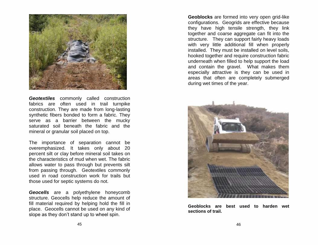
Geotextiles commonly called construction fabrics are often used in trail turnpike construction. They are made from long-lasting synthetic fibers bonded to form a fabric. They serve as a barrier between the mucky saturated soil beneath the fabric and the mineral or granular soil placed on top. The importance of separation cannot be overemphasized. It takes only about 20 percent silt or clay before mineral soil takes on the characteristics of mud when wet. The fabric allows water to pass through but prevents silt from passing through. Geotextiles commonly used in road construction work for trails but those used for septic systems do not. Geocells are a polyethylene honeycomb structure. Geocells help reduce the amount of fill material required by helping hold the fill in place. Geocells cannot be used on any kind of slope as they don’t stand up to wheel spin.
45
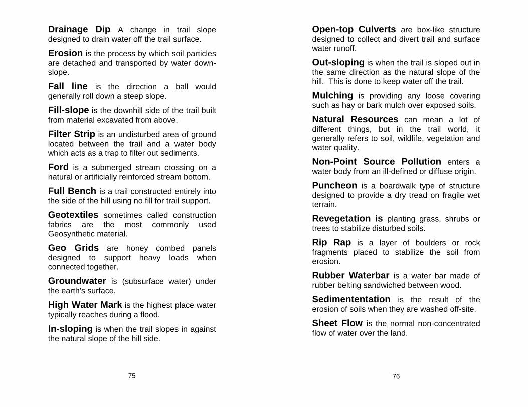
Geoblocks are formed into very open grid-like configurations. Geogrids are effective because they have high tensile strength, they link together and coarse aggregate can fit into the structure. They can support fairly heavy loads with very little additional fill when properly installed. They must be installed on level soils, hooked together and require construction fabric underneath when filled to help support the load and contain the gravel. What makes them especially attractive is they can be used in areas that often are completely submerged during wet times of the year.
Geoblocks are best used to harden wet sections of trail.
46

Some locations may allow for a variety of treatment options depending on anticipated user group, soil types and availability of materials.
Be sure to talk with experienced trail builders in the area before beginning construction because there may be a simple workable solution that is less expensive or easier to install
47
Crossing Streams and Rivers Stream and River crossings present a challenge to trail managers grappling with a mix of safety, convenience, cost, anticipated use, and environmental impact. A shallow stream ford may be appropriate if it is environmentally sound. Each kind of water crossing has consequences for the recreation experience and the lands being accessed. Carefully consider all your options before committing present and future resources to any given crossing.
Shallow Stream Fords
The idea behind a shallow stream ford is to provide solid footing, from the top of one bank to the other. Most fords are not designed to be used during high runoff, but are intended to be used when flows are moderate to low. A ford should never be more than a foot deep. Fords should be located where the stream or river flow is wide and straight with little current. Approaches should be on a gentle slope from a slight upstream angle; cross the stream at a perpendicular angle; and climb gently out and head slightly upstream. The idea is to have an even flow through the ford so the material isn't washed away. Fords should never approach or depart from downstream; doing this could provide a new channel for the stream during a high-water event.
48

If a ledge or rock gravel bottom doesn’t exist you will need to harden it and armor the approaches to prevent erosion. Concrete planks or cable concrete blocks can strengthen the trail tread for a solid crossing.
Fords can cause problems for spawning fish especially salmon so they need to be correctly designed and only used in appropriate locations. For those reasons they usually require a full permit from DEP or LURC. Always consider an alternative to a ford before planning to build one. If it is going to be built the work must be done during the driest part of the year, usually July/August.
Maintenance consists of retaining an even shallow flow with solid footing. Watch for deep spots developing in the crossing. Floods or seasonal runoff can wash away the approaches or deposit debris and alter flow
characteristics. It is important to maintain solid approaches in order to prevent sedimentation.
49
Culverts
Culverts are used to allow water to pass beneath the trail from one side to the other.
Culverts should be installed when: ● the trail needs to cross a small brook, or
seasonal runoff which isn’t big enough to require a bridge.
● the water volume in a ditch requires it to be
drained to the opposite side of the trail.
Culvert Strengths: Provide for a smooth uninterrupted trail.
Culvert Weaknesses: Require regular inspections and cleaning;
Failure caused by lack of maintenance or a heavy rain event can be expensive to repair;
Are more easily plugged by beavers than bridges.
50

Box culvert: no gravel cover
Culvert Installation Tips
Install the culvert so that:
culvert is at a 2% grade (¼-inch of drop per foot of length).
round plastic culverts must have at least one foot of gravel covering it.
earth or gravel is compacted around the culvert for its full length.
rock riprap is installed on both ends of the culvert at a 2 to 1 slope with end of culvert extending beyond the fill to prevent erosion.
Culverts installed in natural streams should be embedded into the streambed to allow fish to travel freely through the culvert. A better option is a bottomless (box) culvert or a bridge.
51
Culvert Sizing
It is very important to have the proper culvert length. All too often, people install culverts that are too short, causing the shoulder around the culvert to collapse and plug the openings. Both ends should extend at least a foot beyond the edge of the fill over the culvert.
Stream Width
(inches at normal high water mark)
Stream Depth
(inches at normal high water mark)
Culvert Size
(inches diameter)
6 6 15
9 6 15
9 9 18
12 6 18
12 9 22
12 12 24
18 9 30
Culvert diameter is the most important aspect of culvert selection. Proper sizing can eliminate washouts and plugging. Money spent for a larger culvert often results in a net savings because of reduced maintenance and repair. A minimum diameter of 15 inches for round culverts is recommended. Smaller culverts plug too easily and are hard to clean. Culverts must be large enough to handle expected flows with openings designed to accommodate at least a 25-year storm flow; this means the opening must be at least 3½ times the cross-sectional area of the stream: (Average depth x average width) x 3.5
52

Determine the opening size needed to accommodate the expected flood event.
To accommodate normal high water (1-3 year flood); multiply width x average depth at high water mark.
Width of normal high water
0.5’ 1.5’ 1.0’
When installing culverts:
Set the culverts with the bottoms slightly below the stream crossing, extend the inlet and outlet 1’ or more beyond the fill or trail-bed, cover with compacted backfill to a depth equal to half the culvert diameter or at least 1’ deep, stabilize the inlet and outlet of culverts and bridges using cobbles, timber abutments or other armoring.
Inlet and outlet at or below stream bed
53
Culvert Types
There are four basic types of culverts used in trail construction: corrugated metal, plastic, concrete and wood box culverts. Each has advantages and disadvantages, as shown in the following table.
Culvert Type
Advantage Disadvantage
metal inexpensive for sizes < 24”
easy to install 25-year life
expensive for sizes > 24”
heavier to handle
plastic inexpensive for sizes < 18”
>25-year life easily cut with
power saw lightweight
easily broken if not handled carefully
more difficult to install
easily crushed
concrete 50-year life handles heavier
weights
expensive very heavy
hard to handle
wood strong (when built with 4x6 or larger material)
>25 year life (when built from P.T. lumber)
no impact to stream bottom
No fill required easy to transport does not require
heavy equipment
usually have to be built on site.
pre built box culverts are heavy and hard to move
expensive
54

Open-Top Cross Drain
Open-Top cross drains can be very effective when used on trails for ATVs and snowmobiles but can create a challenge for dirt bikes, horses, and bicycles. If used on multi-use trails a protective top grate must be used. These box-like structures collect and divert both trail and surface water runoff away from the trail combining the jobs of a waterbar and culvert into one. Open-top culverts can be constructed of logs or from sawn lumber. If constructed of pressure treated lumber, they will last for many years. Open-top culverts should drain into stable vegetated filter strips. They will need to be cleaned regularly to remove debris and sediment.
55
Bridges
Use bridges at median to large stream or river crossings and when site conditions make a bridge more practical than a culvert or ford. Small bridges are fairly easy to construct but once spans exceed 30-40 feet, bridges become a greater challenge often requiring engineered plans and significant funding. The span length, remoteness of location, weight capacity, and design all affect cost. Before you build a bridge, weigh your site options carefully to make the best choice. When building a bridge, it is important to avoid or minimize bank disturbance. Abutments may be needed to reduce the span length and/or support the bridge weight. Piers or islands can be used to break the entire distance into shorter spans. However, DEP/LURC and the Army Corps of Engineers will be concerned about structures in the water channel, so always scout for a location carefully to avoid piers if possible. Bridge Strengths:
No impact to stream channel
Very little fill needed
Won’t plug up Bridge Weaknesses:
May require engineering
More time consuming
Railings or bumpers required
Long-term maintenance required
As with culverts bridges should be designed to accommodate at least a minimum 25-year storm flow.
56

Considerations for Bridge Installation
Safe, strait, nearly level approaches are best. If possible avoid ramps.
The availability of materials and ease to get them on site.
Required clearance for watercraft etc.
Required capacity? Normal operation may only require it to hold several ATVs, but other uses and may require load capacities of 5+ tons (tractor/groomer).
Who else will use it? Horses or snowmobile grooming equipment may require stronger decking and stringers.
Basic Bridge Structural Components
Abutments & Supports
Stringers
Decking
Railings
57
Abutments & Supports
Bridge abutments and supports provide the “seats” on which the bridge structure rests. They can be log sleepers, large flat rock slabs, stone filled log cribs, wood or steel pilings, precast or poured concrete. The purpose is to provide a solid foundation and keep the stringers high and dry to prevent rot.
With the exception of sleepers and pilings, most abutment and support options require some degree of stream bank excavation for installation. It is this aspect of bridge construction that requires the greatest attention to environmental impacts and protection against erosion and sedimentation. Installation of abutments behind the natural stream back is preferred.
Stringers
The stringer is the primary support device for the bridge deck. These are beams that extend between abutments and/or in-stream supports. Stringers can be logs, utility poles, timbers (solid or laminated), steel beams, or fabricated trusses of either wood or steel. The correct choice depends on length of span, weight capacities, availability, and construction cost. Laminating beams (nailed and glued at staggered lengths) can greatly increase the strength of wood stringers. Knee braces between stringers and abutments can also significantly increase load capacities. If you are unsure of capacity it is best to err on the side of strength. The cost of an extra stringer, or larger size, is a small price to pay and peace of mind.
58

For wood construction, pressure-treated is hard to beat with a number of northeastern firms producing affordable, treated, woods with life expectancies of 40 years. Naturally rot-resistant species should be used if pressure treated wood is not an option. Hemlock or tamarack are both good choices but Cedar is generally too weak for structural components. All log stringers will last more than twice as long if the bark is peeled, and the ends are kept free of soil contact (i.e., set on rocks or sleepers). If a span exceeds 40 feet, stringer options should be evaluated by a professional. Metal beams or trusses are an excellent choice especially if they are readily available. If a span exceeds 100 feet, suspension bridges may be the best and most affordable choice.
59
60

Decking
Most trail bridge decks are built from planking 2 to 4 inches thick and 6 to 10 inches wide. (Equestrian use requires thicker decking and snowmobile use requires wear strips.) Pressure-treated wood, hemlock or tamarack are all good choices. Decking should be placed with tree growth rings curving down. This encourages water to run off rather than soak in and helps to prevent cupping. Costs of decking can sometimes be reduced by using running boards on top, and perpendicular to, the base layer of deck planking. Running boards help distribute the impact of heavy loads thereby reducing the need to depend on deck planking alone for weight-bearing support.
Railings
Railings should be strong and high enough to protect users. Inadequate railings become an attractive nuisance and are a safety hazard. Wood railing should be made out of at least 2x6’s or larger material. They should be bolted or screwed together rather than nailed. If possible braces should also be installed.
The railings on a high bridge in urban areas may need to be designed to prevent small children from falling through openings. Smaller more remote bridges may just need bumpers. Railings should always be at least 30 inches high and designed so they don’t attract people to sit or walk on them.
61
Bridge Maintenance Tips (annually)
Thoroughly inspect stringers, ramps, decking, railings and abutments.
Check for rot, splits, and insect damage.
Replace loose screws, nails, and bolts.
Maintain approaches so water and sedimentation don’t drain onto the bridge or into the stream.
Look for erosion, as well as displaced logs or rocks that could cause problems.
Any of the following problems require immediate attention to determine whether the bridge should remain open to traffic:
Rotten, missing or broken materials.
Large areas of damage from storms, accidents, rust, or insects.
Broken, eroded, or rusted supports.
62

63
64

Ten Foot Wide, Four Beam Bridge Max 15,000 Pounds
Beam Dimensions and Unbraced Length
Span (Ft)
Depth (In.)
Flange Width (In.)
Flange Thicknes
s (In.)
Max unbraced Length (feet)
W10
30 W10x77 10 5/8 10 1/4 7/8 5’ - 1”
W12
30 W12x58 12 1/4 10 5/8 10’-7”
W14
30 W14x48 13 3/4 8 5/8 8’-6”
40 W14x90 14 14 1/2 11/16 15’-3”
W16
30 W16x40 16 7 1/2 7’-4”
40 W16x77 16 1/2 10 1/4 3/4 10’-10”
W18
30 W18x35 17 3/4 6 7/16 6’-3”
40 W18x65 18 3/8 7 5/8 3/4 8’-0”
50 W18x106 18 3/4 11 1/4 15/16 11’-9”
W21
30 W21x44 20 5/8 6 1/2 7/16 6’-7”
40 W21x57 21 6 1/2 5/8 6’-10”
50 W21x83 21 3/8 8 3/8 13/16 8’-8”
W24
30 W24x55 23 5/8 7 1/2 7’-0”
40 W24x55 23 5/8 7 1/2 7’-0”
50 W24x68 23 3/4 9 9/16 9’-6”
65
Ten Foot Wide, Three Beam Bridge Max 15,000 Pounds
Beam Dimensions and Unbraced Length
Span (ft)
Depth (In.)
Flange Width (In.)
Flange Thicknes
s (In.)
Max unbraced Length (feet)
W12
30 W12x96 12 3/4 12 1/8 7/8 12’-10”
W14
30 W14x82 14 1/4 10 1/8 7/8 10’-8”
W16
30 W16x67 16 3/8 10.25 11/16 10’-9”
W18
30 W18x55 18 1/8 7 1/2 5/8 10’-10”
40 W18x97 18 5/8 11 1/8 7/8 11’-9”
W21
30 W21x44 20 5/8 6 1/2 7/16 6’-7”
40 W21x83 21 3/8 8.375 13/16 8’-9”
W24
30 W24x55 23 5/8 7 1/2 7’-0”
40 W24x68 23 3/4 9 9/16 9’-6”
50 W24x103 24 1/2 9 1 9’-6”
66

Ten Foot Wide, Two Beam Bridge Max 15,000 Pounds
Beam Dimensions and Unbraced Length
Span (Ft)
Depth (In.)
Flange Width (In.)
Flange Thickness
(In.)
Max unbraced Length (feet)
W12
30 W12x87 12 1/2 12 1/8 13/16 12’-9”
W14
30 W14x74 14 1/8 10 1/8 13/16 10’-7”
W16
30 W16x57 16 3/8 7 1/8 11/16 7’-6”
40 W16x100 17 10 3/8 1 11’-0”
W18
30 W18x50 18 7 1/2 9/16 7’-10”
40 W18x86 18 3/8 11 1/8 3/4 11’-8”
W21
30 W21x44 20 5/8 6 1/2 7/16 6’-6”
40 W21x73 21 1/4 8 1/4 3/4 8’-9”
W24
30 W24x55 23 5/8 7 1/2 7’-0”
40 W24x62 23 1/4 7 9/16 7’-4”
50 W24x94 24 1/4 9 1/8 7/8 9’-7”
W30
30 W30x90 29 1/2 10 3/8 9/16 10’-0”
40 W30x90 29 1/2 10 3/8 9/16 10’-0”
50 W30x90 29 1/2 10 3/8 9/16 10’-0”
67
Five Foot Wide, Two Beam Bridge Max 5000 Pounds
Beam Dimensions and Unbraced Length
Span (Ft)
Depth (In.)
Flange Width (In.)
Flange Thickness
(In.)
Max unbraced Length
(ft)
W8
30 W8X58 8 3/4 8 1/4 15/16 8’-8”
W10
30 W10X45 10 1/8 8 5/8 8’-6”
40 W10X100 11 1/8 10 3/8 1 1/8 10’-10”
W12
30 W12X30 12 3/8 6 1/2 7/16 6’-10”
40 W12X79 12 3/8 12 1/8 3/4 12’-9”
W14
30 W14X26 13 7/8 5 7/16 5’-3”
40 W14X61 13 7/8 10 5/8 10’-7”
W16
30 W16X26 15 3/4 5 1/2 3/8 5’-7”
40 W16X50 16 3/4 7 1/8 5/8 7’-6”
50 W16X89 16 3/4 10 3/8 7/8 10’-10”
W18
30 W18X35 17 3/4 6 7/16 6’-4”
40 W18X46 18 6 5/8 6’-4”
50 W18X76 18 1/4 11 11/16 11’-7”
W21
30 W21X44 20 5/8 6 1/2 7/16 6’-7”
40 W21X44 20 5/8 6 1/2 7/16 6’-7”
50 W21X62 21 8 1/4 5/8 8-‘8”
W24
30 W24X55 23 5/8 7 1/2 7’-0”
40 W24X55 23 5/8 7 1/2 7’-0”
50 W24X55 23 5/8 7 1/2 7’-0”
W30
30 W30X90 29 1/2 10 3/8 9/16 10’-0”
40 W30X90 29 1/2 10 3/8 9/16 10’-0”
50 W30X90 29 1/2 10 3/8 9/16 10’-0”
68

Trail Maintenance
Maintaining the trail involves the removal of brush blow downs and other encroaching plants such as thistles or berry bushes which may block the trail. It also involves filling ruts, holes, and low spots and removing or covering obstacles such as protruding roots and rocks. You may also need to repair sections that have been damaged due to significant use, landslides or washouts. Proper tread maintenance aims for a solid, out-sloped or crowned surface. Remove all debris that has fallen on the trail. Pull the lower edge berm back onto the tread surface and use it to restore the crown or out-slope of the trail. Diverting surface water off the trail should be at the top of your list of priorities. An insufficient crown will allow water to puddle on the surface; this will create potholes or erode the trail. Potholes will continue to grow each time a vehicle splashes through them. Standing water will also seep into the trail weakening it and making it susceptible to rutting. A general rule for gently sloping gravel trails is ¼-inch of crown per foot of total width. A crown of ½ inch per foot of trail width may be necessary for steeper sections to counteract the tendency of water to collect and travel downhill. Out-sloped trails should also be between ¼ and ½ inch per foot of width. Annual maintenance is normally required to maintain the correct amount of out-slope or crown.
69
Grading
Grading is the process of smoothing and crowning a trail. This involves using a tractor, grader, or bulldozer with a steel cutting blade to redistribute soil material. Generally large graders are only used on large gravel trails like rail beds or forest management roads. Regular grading or raking is an effective means of redistributing material that has either been washed or pushed to the edge by vehicle traffic. Over time, as the soil compacts, a berm will often form at the downhill edge of the trail. These little ridges will defeat the purpose of crowning by catching water before it can drain off. Always make sure that water can get off the trail by smoothing the edge with the grading blade or rock rake. Usually, trails are graded by scraping pulling the material from the outer edge back into the center. Proper grading is also the most effective means of removing potholes. The grader should cut to the full depth of the potholes. Otherwise, they will tend to reform very quickly. The best time to grade is when the ground is moist (in the spring after the frost has gone, or after a rain). Water helps to loosen the gravel and makes the road easier to reshape.
A word of caution – job performance is as good as the equipment operator! A trained and experienced contractor may be more expensive, but the job he does may be better, and last longer. Check references, and make sure they understand the work you need done.
70

A Steel tine rake, commonly called a York rake is another affordable and effective
piece of maintenance equipment. This device consists of a row of strong metal tines that work in much the same manner as a grader blade. They can be towed behind or mounted on the front of an ATV, tractor, or truck.
Steel tine rakes can be used to: remove small potholes and wash-
boarding; establish and maintain proper crown; remove ridges of material from the
shoulder to allow for better drainage.
Advantages of this type of device include: Less expensive than graders. Ease of use, less time to grade.
Disadvantages include: Won’t cut like a grader blade. Takes more passes for some tasks.
71
Mud Holes
Mud puddles may produce tread damage but mud holes can have a more significant impact on the environment. Every attempt should be made to keep all trails high and dry. Standing water usually weakens the tread and can cause a muddy/boggy area to develop. Usually these areas get wider and deeper as the existing trail gets harder to negotiate. Eventually a small muddy section will turn into a wide nearly impassable trail if the problem isn’t quickly and effectively addressed. It is important that natural wetlands and sensitive areas such as vernal pools not be damaged by ATV use. Many muddy sections of trail are in problem areas. In most cases the best option is to relocate trails to more appropriate and easier maintained locations or use trail hardening and stabilization techniques. Mud runs and challenge areas should only be located in approved environmentally sound locations where you have permission from both the landowner and the appropriate environmental agency. Challenge areas and mud runs should always have a good alternative trail around them for those who don’t have a 4-wheel drive machine capable of negotiating the trail or for those who prefer to stay on easy more stable trails.
72

Closing Trails
Discontinued trails should be blocked and/or gated to prevent unauthorized use and damage. When the trail is closed, measures should be taken to discontinue use by removing signs and structures, pulling culverts/bridges, installing water bars, or other effective stabilizing measures.
Past practices of trail abandonment have left safety issues and permanent scars on the land. You probably know of abandoned trails that had a few logs and rocks dragged into the tread and trenches. Years later they are still visible, ugly and in many cases still eroding.
There are no cookbook answers for returning abandoned trails to their natural condition. Each site should be evaluated for its potential to regenerate and heal.
Revegetation can be accomplished passively or actively. Passive revegetation allows surrounding vegetation to naturally overtake the abandoned trail. Active revegetation ranges from spreading appropriate mulch, seed or transplanting onsite vegetation.
Simple restoration may consist of blocking new shortcuts and allowing the vegetation to recover. Complex restoration projects include reshaping the trail and replanting genetically appropriate species. Careful monitoring and follow up may be necessary to ensure that almost all evidence of the trail is gone. Thus, restoration can range from simple and inexpensive to complex and costly.
73
Definitions
Abutments The structures designed to support bridges or boardwalks.
Back-slope is the excavated, exposed area
on the hillside above the trail.
Best Management Practices (BMP’s) the most effective, practical, and economically feasible means of preventing water pollution.
Borrow Pit the area from which soil is
excavated.
Boardwalk a planked bridge like structure
erected across wetlands.
Clearing limit the area from which
vegetation and other obstacles are removed to allow safe passage.
Clinometer a tool used to measure grade or
slope.
Climbing Turn less than 180 degree turn
used to go up hill while maintaining the existing trail grade.
Corduroy a primitive type of puncheon made
by laying logs on the ground side by side.
Cribwall is a retaining structure made of
wood and rocks designed to keep dirt in place.
Culvert is a wood, metal, plastic, or concrete
structure under the trail to allow water to cross.
Down-slope is the down hill side of the trail.
74
Drainage Dip A change in trail slope
designed to drain water off the trail surface.
Erosion is the process by which soil particles
are detached and transported by water down-slope.
Fall line is the direction a ball would
generally roll down a steep slope.
Fill-slope is the downhill side of the trail built
from material excavated from above.
Filter Strip is an undisturbed area of ground
located between the trail and a water body which acts as a trap to filter out sediments.
Ford is a submerged stream crossing on a
natural or artificially reinforced stream bottom.
Full Bench is a trail constructed entirely into
the side of the hill using no fill for trail support.
Geotextiles sometimes called construction
fabrics are the most commonly used Geosynthetic material.
Geo Grids are honey combed panels
designed to support heavy loads when connected together.
Groundwater is (subsurface water) under
the earth's surface.
High Water Mark is the highest place water
typically reaches during a flood.
In-sloping is when the trail slopes in against
the natural slope of the hill side.
75
Open-top Culverts are box-like structure
designed to collect and divert trail and surface water runoff.
Out-sloping is when the trail is sloped out in
the same direction as the natural slope of the hill. This is done to keep water off the trail.
Mulching is providing any loose covering
such as hay or bark mulch over exposed soils.
Natural Resources can mean a lot of
different things, but in the trail world, it generally refers to soil, wildlife, vegetation and water quality.
Non-Point Source Pollution enters a
water body from an ill-defined or diffuse origin.
Puncheon is a boardwalk type of structure
designed to provide a dry tread on fragile wet terrain.
Revegetation is planting grass, shrubs or
trees to stabilize disturbed soils.
Rip Rap is a layer of boulders or rock
fragments placed to stabilize the soil from erosion.
Rubber Waterbar is a water bar made of
rubber belting sandwiched between wood.
Sedimententation is the result of the
erosion of soils when they are washed off-site.
Sheet Flow is the normal non-concentrated
flow of water over the land.
76

Silt Fence is a geotextile product designed
and installed to prevent off-site movement of soils.
Streams are natural water channels that may
flow year round or only part of the year.
Stringers are the primary support devices for
a bridge decking.
Surface Water is water that is flowing or
standing on the top of the ground.
Switchback is a sharp 180 degree hillside
turn to reduce the trail grade on steep slopes.
Trail Grooming is generally known as
moving snow, cutting snow moguls and packing a smooth snow surface.
Trail Tread is where the rubber meets the
ground.
Trail Corridor is the zone including the trail
tread and the area to the sides of it.
Turnpike is a raised section of trail consisting
of ditches on both sides to improve drainage.
Turnouts used in conjunction with ditching to
direct water away from the trail into a filter strip.
Waterbar is a water deflector installed at a
45 degree angle across the trail.
Watershed is the surrounding land area that
drains into a particular lake or river system.
Wetland is an area where soils are flooded or
saturated a significant part of the year.
77
Wire gabion is a wire basket filled with rocks
and stacked as a retaining wall.
Vernal Pools are a special type of forested
wetland deserving special consideration.
Notes
78

Determine the opening size needed to accommodate the expected flood event.
To accommodate normal high water, multiply width x average depth at high water mark.
Width of normal high water
0.5’ 1.5’ 1.0’
Opening must be the Average depth x average width) x 3.5 ½ times the cross-sectional area of the stream.
25-Year Flood Crossing Opening Size (sq. ft)
*Average Stream Depth in Feet
*Width in Feet
0.5 1 1.5 2
1 1.75 3.5 5.25 7.0
2 3.5 7.0 10.5 14
3 5.25 10.5 15.8 21
4 7.0 14 21 28
5 8.75 17.5 26.3 35
6 10.5 21 31.5 42
* At normal high water mark Bold: Bridge, arch, or multiple pipes may be preferred on these larger streams
79
Culvert Diameter and Opening Size
Opening Size (Sq. ft.)
Diameter (inches)
0.20 6
0.80 12
1.25 15
1.75 18
2.40 21
3.15 24
4.90 30
7.05 36
9.60 42
12.55 48
15.90 54
19.65 60
23.75 66
28.26 72
Notes
80