best practice guide flow products - … · as a part of abb, a world leader in ... 4 programming a...
TRANSCRIPT

Best Practice GuideIM/FLWBPG Issue 1
Flow ProductsAquaProbe

ABBEN ISO 9001:2000
Cert. No. Q 05907
EN 29001 (ISO 9001)
Lenno, Italy – Cert. No. 9/90A
Stonehouse, U.K.
The Company
We are an established world force in the design and manufacture of instrumentation forindustrial process control, flow measurement, gas and liquid analysis and environmentalapplications.
As a part of ABB, a world leader in process automation technology, we offer customersapplication expertise, service and support worldwide.
We are committed to teamwork, high quality manufacturing, advanced technology andunrivalled service and support.
The quality, accuracy and performance of the Company’s products result from over 100 yearsexperience, combined with a continuous program of innovative design and development toincorporate the latest technology.
The UKAS Calibration Laboratory No. 0255 is just one of the ten flow calibration plantsoperated by the Company and is indicative of our dedication to quality and accuracy.
Information in this manual is intended only to assist our customers in the efficient operation of our equipment. Use of thismanual for any other purpose is specifically prohibited and its contents are not to be reproduced in full or part without priorapproval of the Technical Publications Department.
Health and Safety
To ensure that our products are safe and without risk to health, the following points must be noted:
1. The relevant sections of these instructions must be read carefully before proceeding.2. Warning labels on containers and packages must be observed.3. Installation, operation, maintenance and servicing must only be carried out by suitably trained personnel and in accordance with
the information given.4. Normal safety precautions must be taken to avoid the possibility of an accident occurring when operating in conditions of high
pressure and/or temperature.5. Chemicals must be stored away from heat, protected from temperature extremes and powders kept dry. Normal safe handling
procedures must be used.6. When disposing of chemicals ensure that no two chemicals are mixed.
Safety advice concerning the use of the equipment described in this manual or any relevant hazard data sheets (where applicable) may be obtained from the Company address on the back cover, together with servicing and spares information.

Flow ProductsAquaProbe Contents
IM/FLWBPG Issue 1 1
Contents
1 Introduction ...................................................................................................................................... 41.1 Comprehensive User Features and Benefits ............................................................................ 51.2 Use .......................................................................................................................................... 5
2 Sales Benefits and Highlights ......................................................................................................... 62.1 AquaProbe™ – The Total Quality Insertion Meter ..................................................................... 62.2 Designed for the Water Industry ............................................................................................... 7
3 AquaProbe Insertion Meter ............................................................................................................. 83.1 Vortex Shedding Effect .......................................................................................................... 11
3.1.1 Maximum Permissible Length ...................................................................................... 123.2 Measuring the Internal Diameter ............................................................................................ 133.3 Installation ............................................................................................................................. 14
3.3.1 Method 1 – Fig. 3.7 ..................................................................................................... 143.3.2 Method 2 – Fig. 3.8 ..................................................................................................... 163.3.3 Mean Velocity Method – Fig 3.9 ................................................................................... 18
4 Programming a MagMaster Transmitter ..................................................................................... 204.1 Internal Diameter ................................................................................................................... 204.2 Profile Factor ......................................................................................................................... 204.3 Insertion Factor ..................................................................................................................... 20
5 Programming an AquaMaster Transmitter .................................................................................. 215.1 AquaMaster Passwords / Level Entry ..................................................................................... 215.2 Menu 9 – Flow Cal ................................................................................................................. 22
6 AquaMaster Programming ........................................................................................................... 236.1 Hyper-terminal Connection Procedure ................................................................................... 246.2 Setting up the Modem (Initializing) .......................................................................................... 25
6.2.1 General Connection Strings for AquaMaster ................................................................ 256.3 Menu Structure ..................................................................................................................... 26
6.3.1 Navigation Mode ......................................................................................................... 266.3.2 Command Mode ........................................................................................................ 26
6.4 AquaMaster Passwords/Level Entry ....................................................................................... 266.5 Information ............................................................................................................................ 27
6.5.1 Useful Command Mode Variable Locations ................................................................. 286.6 Measurements ....................................................................................................................... 29
6.6.1 Useful Command Mode Variable Locations ................................................................. 306.7 Display Options ..................................................................................................................... 31
6.7.1 Useful Command Mode Variable Locations ................................................................. 316.8 Access .................................................................................................................................. 32
6.8.1 Write Access Levels .................................................................................................... 326.8.2 In-built Tamper-proof Switch ....................................................................................... 326.8.3 Useful Command Mode Variable Locations ................................................................. 32
6.9 Flow Settings ......................................................................................................................... 336.9.1 Engineering Units ........................................................................................................ 346.9.2 Useful Command Mode Variable Locations ................................................................. 34
Flow ProductsAquaProbe Contents
2 IM/FLWBPG Issue 1
6.10 Pressure Settings (AquaMaster S only) ...................................................................................356.10.1 Engineering Units .......................................................................................................356.10.2 Useful Command Mode Variable Locations ................................................................35
6.11 Transducer Pressure Setup (AquaMaster S only) ....................................................................366.11.1 Changing Pressure Transducer Data ..........................................................................366.11.2 User Span and Zero Adjustment ................................................................................36
6.12 Outputs ..................................................................................................................................376.12.1 Input/Output Connections ..........................................................................................376.12.2 Default Settings ..........................................................................................................386.12.3 Useful Command Mode Variable Locations ................................................................38
6.13 Flow Calibration .....................................................................................................................396.13.1 Profiling ......................................................................................................................396.13.2 Default Flow Measurement Mode (Maximum Battery Life) ...........................................39
6.14 Tariff Control ..........................................................................................................................406.14.1 LCD Display ...............................................................................................................406.14.2 Serial Communications Interface RS232 .....................................................................406.14.3 LogMaster ..................................................................................................................406.14.4 Tariff Control ..............................................................................................................40
6.15 Logger ..................................................................................................................................456.16 GSM Communications Settings (v2.4x Software) ..................................................................46
6.16.1 Commissioning – Signal Strength Test .......................................................................466.16.2 SIM Numbers .............................................................................................................466.16.3 GSM WakeUp Control ................................................................................................476.16.4 Access via SMS Text Message ..................................................................................476.16.5 SMS Request Message .............................................................................................48
6.17 SMS Services ........................................................................................................................496.17.1 Non-persistent Variables ............................................................................................516.17.2 Persistent Variables Stored in AquaMaster Transmitter ...............................................526.17.3 Persistent Variables Stored in AquaMaster Sensor .....................................................53
7 SMS Logger Server Software .......................................................................................................547.1 Installing SMS Logger Server Software .................................................................................557.2 AquaMaster Setup for Logger Messages via SMS ..................................................................57
8 MagMaster Programming and Menu Structure ...........................................................................59
9 MagMaster On-site Servicing .......................................................................................................689.1 Sensor ...................................................................................................................................689.2 The Electrodes .......................................................................................................................689.3 MagMaster Transmitter ..........................................................................................................70
9.3.1 Problem Solving Tests For MagMaster .........................................................................719.3.2 Electrode Measurements ............................................................................................719.3.3 MagMaster Connections ..............................................................................................729.3.4 Transmitter Connected to Sensor ................................................................................729.3.5 Transmitter Disconnected From Sensor .......................................................................72

Flow ProductsAquaProbe Contents
IM/FLWBPG Issue 1 3
10 AquaMaster On-site Service ........................................................................................................ 7310.1 MIL Spec 19-Pin Connector ................................................................................................. 7510.2 Battery Alarm / Replacement Sequence ............................................................................... 76
10.2.1 Spares – Battery Assembly Kits ................................................................................. 7710.2.2 Battery Changing Procedures ................................................................................... 77
10.3 AquaMaster Field Service Report .......................................................................................... 78
11 Fault Finding Flow Charts ............................................................................................................. 79
Notes ................................................................................................................................. 89

Flow ProductsAquaProbe 1 Introduction
4 IM/FLWBPG Issue 1
1 IntroductionThe AquaProbe is an electromagnetic insertion flowmeter. It operates on exactly the same principle as anyfull-bore electromagnetic flowmeter, with coils, electrodes and a magnetic core. However, for AquaProbe,the layout is reversed; instead of the water flowing through the flowmeter it flows around it. It is, in effect, aninside-out electromagnetic flowmeter.
The idea of an insertion meter is not new; there are several different types on the market from Pitot typessuch as Annubar that are differential pressure devices, to Turbine devices such as Quadrina and, indeed,some other electromagnetic devices.
The Pitot device is a tube that is inserted into the flow and measures the drop in pressure due to velocity ofthe medium. This drop in pressure can then be converted into flow units. The turbine device is just a smallpropeller on the end of a probe that, when inserted into the flow, is rotated by the liquid passing by andagain gives an output proportional to velocity. As the turbine is a mechanical device it requires routine andregular maintenance to ensure that the bearings are in good condition. If no filters are installed in the line,the turbine can easily be damaged by particles in the flow. Finally, a Turbine flowmeter is incapable ofmeasuring low velocities because friction in the bearings causes the turbine to slow down significantly andfinally stall or stop. This is a widely used device at present, although its use is beginning to decline in favourof the more useful electromagnetic probes.
The AquaProbe is available for use with two different transmitters: AquaMaster and MagMaster.
MagMaster Transmitter
32-character display option
Surface mount
Choice of language
Multiple self-monitoring and diagnostic functions
Switch mode power supply AC or DC
Fully programmable
Forward/Reverse/Nett flow
AquaMaster Transmitter
32-character display
Surface mount
Choice of language
Multiple self-monitoring and diagnostic functions
Mains/battery operation
Internal flow and pressure loggers
Submersible
Dual pulse output – forward and reverse
Alarm output
RS232 remote communications, GSM (optional)
RS232 (local communications)
Plug and socket connections
Compatible with virtually all data loggers

Flow ProductsAquaProbe 1 Introduction
IM/FLWBPG Issue 1 5
1.1 Comprehensive User Features and BenefitsMagMaster Transmitter
Analog output (fully programmable)
Dual analog output (optional)
Dual pulse output – forward and reverse – 0 to 800Hz
Dual alarm outputs – for example, flow rate, empty pipe, fault conditions etc.
RS422/423 (optional)
RS232
Totalizer reset
AquaMaster Transmitter
Mains with battery backup:
Battery only
Dual pulse output – forward and reverse – 0 to 50Hz
Remote RS232 (optional)
Local RS232
GSM/SMS compatible (optional)
2 internal flow/pressure loggers fully configurable (optional)
Pressure measurement display (optional)
1.2 UseAn insertion probe can be inserted into a flow-line through a small tapping and a valve fitted to the line. Thetapping can be as small as one inch BSP or larger. Such a tapping is common on pipelines and, if one doesnot exist where it is required to make the installation, it is very inexpensive to fit one, online and underpressure, and there are many specialist companies that do this type of work.
It is important to note that putting any type of device into a pressurized vessel (the pipe) can be dangerous.If the pressure in the line is high (typically 5 bars or more), care must be used in both installing and removingthe probe. If the pressure is greater than 10 bars, installation (or removal) of a probe is not recommended.Instead the pressure should be removed from the line for the short period of time it takes to install orremove the probe, when the pressure can then be re-applied. In many instances, the removal of a probefrom a line is more dangerous than the installation. For this reason, AquaProbe is supplied complete with asafety device that when used prevents rapid outward movement and potential injury to operators. It mustbe stressed that this is a problem with all probe devices, not just AquaProbe; in fact AquaProbe is the onlyone available with a safety device fitted.

Flow ProductsAquaProbe 2 Sales Benefits and Highlights
6 IM/FLWBPG Issue 1
2 Sales Benefits and Highlights
2.1 AquaProbe™ – The Total Quality Insertion Meter
Total Quality Performance:
In-built quality
Flowline 'Just in Time' production
Built to your specification
Fast delivery
In-built reliability
Setting the Standard in Insertion Flow Technology:
Excellent accuracy over a wide flow range
Price virtually independent of pipe diameter
Proven by calibration
Designed for the water industry
'Hot-tap' installation capability
For safe, In-service operation
Suitable for permanent or temporary Installation
Choice of transmitter – AquaProbe™ or MagMaster™
Insertion Probe Installation:
Upstream pipe conditions need at least 25 to 50 diameters (ISO 7145)
Poor conditions can be tolerated by use of profiling
Measurement of pipe diameter is essential
Location of AquaProbe is important
Alignment of AquaProbe is important
Programming of transmitter is essential
True for any Insertion Probe

Flow ProductsAquaProbe 2 Sales Benefits and Highlights
IM/FLWBPG Issue 1 7
2.2 Designed for the Water IndustryInnovative design
Rugged, robust construction
Fully submersible sensor
No moving components – hence no problems with bearing wear, stalling, blockage or calibrationshift
Repairable and serviceable
Reliable maintenance free operation in arduous environments
'Hot-tap' Insertion capability
Permanent installations:
Network management
Leakage monitoring
District metering
Temporary installations:
Surveys
Profiling
Distribution investigation
Checking in-situ flowmeters
Excellent accuracy over wide flow range:
Local velocity ±2 % of reading or ±2 mm/s (±0.08 in/s).
Volume flow – refer to ISO 7145-1982.
Forward and reverse flow measurement.
Accuracy is a Partnership.
Fig. 2.1 AquaProbe™ Accurate measurement of peak day flow and minimal night flows

Flow ProductsAquaProbe 3 AquaProbe Insertion Meter
8 IM/FLWBPG Issue 1
3 AquaProbe Insertion MeterThe AquaProbe can be used in pipes from 200 to >2000 mm (0.66 to 6.60 ft). One essential measurementthat is required is the actual internal diameter. When the probe is inserted into the flow-line it measures thevelocity at a single point, the tip of the probe. Generally, users require the device to measure the volumeflowing, not just the velocity, so the volume needs to be calculated from this point velocity. For this reason,in common with all magnetic flowmeters, the pipe needs to be full during measurement. When the averagemean velocity in the tube is known the volume flow can be calculated easily.
What is the mean velocity in the pipe, and how do we arrive at it?
First, flow conditions within the pipe must be considered. Referring to British Standard BS 1042 (ISO 7145– see Table 3.1), the length of straight pipe required between any upstream flow disturbances and the pointof measurement is between 25 and 50 diameters (unlike full-bore electromagnetic flowmeters that usuallyrequire between 5 and 10 diameters). The reason for this is that a full-bore flowmeter measures the meanvelocity and AquaProbe measures just a point velocity.
Fig. 3.1 on page 9 is a vector diagram showing a fully developed turbulent profile of the flow within a pipe.Such diagrams illustrate the distribution of flow within the pipe. Known as the Flow Profile, it is highest in thecentre falling to zero at either side on the pipe wall. If there is sufficient upstream straight pipe, it can beassumed that there is a profile of this form. In this case if, for example, the pipe is 600 mm in diameter, thevelocity at the centre line is 2 m/s and the flow is 487 l/s
Min Upstream Straight Length
Expressed as Multiples of Diameter
Mean Point Centre Line
90 Degree Elbow or 'T' 50 25
Several 90 Degree Bends (Coplanar) 50 25
Several 90 Degree Bends (Not Coplanar)
80 50
Cone 18 – 36 Degrees 30 10
Diffuser 14 – 28 Degrees 55 25
Fully Open Butterfly 45 25
Fully Open Plug Valve 30 15
Table 3.1 Extract from ISO 7145

Flow ProductsAquaProbe 3 AquaProbe Insertion Meter
IM/FLWBPG Issue 1 9
As the volume flow is known, the mean velocity in the pipe can be calculated – note that it is actually1.722 m/sec lower than the velocity measured on the centre line. Careful Investigation of this profile orvector diagram reveals that the mean velocity of 1.722 m/sec occurs at a point 72.5 mm or 1/8 th of thepipe's diameter in from the edge of the pipe. This point is referred to as the Point of Mean Velocity (for a fullydeveloped turbulent flow profile only). This is true (provided the profile is turbulent and fully developed) forall pipes of all sizes and at all flow rates, and is recognized in the British Standard referred to previously.Therefore, the best position to measure velocity is at the Point of Mean Velocity, i.e. 1/8 th of the diameter infrom the edge of the pipe. By placing the probe at this point a straightforward calculation of volume flowcan be performed – but there is more to be considered …
The Point of Mean Velocity is on the knee of the curve (the velocity at this point is changing rapidly withdistance) so it is necessary to position the probe extremely accurately in order to measure the correctvelocity. If the probe is inserted accurately to 72.5 mm, it is therefore measuring the mean velocity of1.722 m/s which, when multiplied by the area, gives a volume flow of 487 l/s. If the probe is inserted to74 mm instead of 72.5, the velocity measurement is 1.85 m/s instead of the expected 1.722. Multiplyingthis figure by the area results in a volume flow of 523 l/sec – an error of 7.4 %.
On-site it can be very difficult to locate a probe exactly, so this sort of error is quite common. With devicesother than AquaProbe, working under any degree of pressure in the line, inserting a probe to within 10 mmof its intended location is often accepted. Using the calculation above, this produces an error ofapproximately 15 %.
Fig. 3.1 Turbulent Flow Profile
Mean Velocity Factor
Max. Velocity Factor
Rapidly Changing Velocities
Flat Part of Curve
1.722 m/s
2.00 m/s

Flow ProductsAquaProbe 3 AquaProbe Insertion Meter
10 IM/FLWBPG Issue 1
Is there any way this problem can be overcome?
Yes! Referring to Fig. 3.1, in the middle of the pipe, near the centre line, the profile is relatively flat, i.e. theflow velocity does not change very much with distance into the pipe. Therefore, if the velocity is measuredon the centre line, measurement errors due to positional errors (i.e. not locating the probe where required)are very small; hence most users will try to use the centre line measuring position. However, as explainedpreviously, this process gives us the wrong answer, Fortunately there is a mathematical relationshipbetween the velocity at the centre line and the mean velocity within the pipe – the Profile Factor (Fp). Thevalue of Fp can be calculated by an equation (below) or obtained from a graph – see Fig. 3.2.
Fp is calculated as follows:
When the probe insertion position is determined, the effect of putting the probe into the pipe (seeSection 3.1 below) must be calculated. The blockage or insertion effect is termed the Insertion Factor (Fi).
This is a mathematical relationship and can be calculated from the formula
Both calculations are included in the AquaProbe User Guide – see IM/AP.
= Pipe Diameter
= Fluid Density
= Average Fluid Velocity
= Fluid Viscosity
Where:
And:
And:
Fig. 3.2 Profile Factor v Flow Velocity for Pipe Sizes 200 to 2000mm (8 to 78 in.)
Fρ 1r Yb–( )
r--------------------
1n---
–=
D
ρ
v
µ
Yb r 2n2
n 1+( ) 2n 1+( )---------------------------------------
n=
n 1.66 Re( )log=
ReDρν
µ-----------=
Fi 11 38 πD( )⁄( )–---------------------------------=

Flow ProductsAquaProbe 3 AquaProbe Insertion Meter
IM/FLWBPG Issue 1 11
3.1 Vortex Shedding EffectWhen a probe of any sort is inserted into a pipe line, it acts as a bluff body and passing fluids shed vorticesbehind it (as in pictures of cars in wind tunnels). In the case of an unstreamlined probe, these vortices aresignificantly stronger than would be seen on a car and form the basis of a vortex shedding flowmeter thatsome companies manufacture.
The effect of vortex shedding is to cause the probe to vibrate. Vibration will increase as flow velocityincreases and can become sufficiently violent to cause physical damage to the probe. Vortex sheddinginduced vibration affects all probes but, as AquaProbe contains no moving parts, it is affected far less thanany mechanical or turbine type; however, vortex shedding must still be considered. Fig. 3.3 (below)indicates the maximum velocity versus insertion lengths that can be achieved for the centre line and 1/8 thinsertion positions. When using AquaProbe for flow profiling (traversing), the velocity versus insertion lengthis less in comparison to the centre line position, for example, at 1000 mm maximum velocity is 0.98 m/s –see Fig. 3.4 on page 12. Refer to the User Guide for additional information.
Fig. 3.3 Maximum Permissible Velocity for Different Pipe Sizes
!
"#
!
"#
"# "$%
!
"#
!
"#
&' "$

Flow ProductsAquaProbe 3 AquaProbe Insertion Meter
12 IM/FLWBPG Issue 1
3.1.1 Maximum Permissible LengthThe insertion length referred to in the graphs in Figs 3.3 and 3.4 is not the insertion length in the pipe, butthe total effective probe length – see Fig. 3.5.
It is important to add the external length from the fixing point to the insertion length. Failure to do this cangive incorrect information from the graphs, resulting in vortex shedding affecting AquaProbe.
Examples:
A 600 mm pipe with the probe mounted on the centre line has an insertion length of 300 mm.
Maximum velocity at 300 mm is 5 m/s. A typical valve is approximately 250 mm high and thedistance to the support point inside the probe is approximately 100 mm therefore, in this example,the total effective length is 650 mm.
Max velocity at 650 mm is 3.6 m/s.
Fig. 3.4 Maximum Permissible Velocity for Different Insertion Lengths
Fig. 3.5 Effective Probe Length
!
"#
!
"#
() *

Flow ProductsAquaProbe 3 AquaProbe Insertion Meter
IM/FLWBPG Issue 1 13
3.2 Measuring the Internal DiameterWhen a standard full-bore electromagnetic flowmeter is manufactured, it is usually supplied in a nominalbore size of a round figure anywhere between 15 and 2000 mm (for example 600 mm, 700 mm). Rarely areflowmeters precisely this nominal size, but it is not important as the wet flow calibration (performed onABB's UKAS-approved and traceable flow rigs in the UK) compensates for small deviations in size. In thecase of a probe, clearly it can't be tested in the pipe in which it is to be finally installed. It is therefore notpossible to take account of the difference between the nominal or expected internal diameter of the pipeand its actual value.
Since the relationship between the point velocity measurement and the flow depends on the area of thecross section of the pipe (π x the radius squared), an error in the value of the internal diameter of the pipecauses a much greater error in the volume flow measurement due to the 'square effect'. Therefore it isessential, whenever possible, to measure the internal diameter accurately to eliminate this extra source oferrors. ABB supply an internal pipe-measuring probe (Pipe-bore Gauging Tool) for this purpose. The tool isused as follows:
1. Fit the tool into the back of the valve, so that the red line on top of the fitting and the handle of thetool is in line longitudinally with the centre line of the pipe.
2. Open the valve and push the tool in gently until it touches the other side of the pipe.
3. Back off the tool a small amount and rotate the handle through 180° so it is again in line with thelongitudinal axis of the pipe.
4. Push the tool down again carefully until it touches the wall of the pipe. Now, slide the small collar onthe tool down to touch the top of the fitting.
5. Pull the tool back carefully until it touches the top of the pipe. During this withdrawal, take care not totouch the sliding collar. This distance between the top knife-edge of the sliding collar and the top ofthe fitting is the internal diameter of the pipe. Measure this distance using a good quality tape rule.
6. Once the diameter has been measured and recorded, push the measuring tool back into the pipe alittle then turn it through 180° so that the handle is once more in line with the longitudinal axis of thepipe and in the same direction as the red line on the top fitting.
7. Retract the probe fully into its fitting and close the valve fully.
Fig. 3.6 Pipe-bore Gauging Rod

Flow ProductsAquaProbe 3 AquaProbe Insertion Meter
14 IM/FLWBPG Issue 1
3.3 InstallationThe decision on where to locate the probe is determined by three factors:
the requirement to put the probe on the centre line
the probe's length
the maximum flow velocity
The probe can be located anywhere in the cross section, but the traditional 2 points are the centre line(maximum velocity point) or the 1/8 th diameter (mean velocity point). For reasons outlined previously, thecentre line is preferable because it is less susceptible to positional errors but the mean velocity point is asgood if care is taken. However, it is usual to install the probe on the centre line and there are 2 methods ofdoing this, depending on the length of the probe.
3.3.1 Method 1 – Fig. 3.7If the probe is long enough to reach the other side of the pipe, this is the preferred method of installation onthe centre line. This procedure involves installing the probe into the valve, opening the valve, inserting theprobe until it gently touches the other side of the pipe, sliding the positioning collar down the shaft to meetthe locking nut and locking the collar in place. Next, the probe is withdrawn fully, although not removedfrom the pipe. The collar is then slipped down the probe a distance of half of the pipe's diameter, less30 mm. The reason for this is that although the probe is moved half a diameter to get the tip onto the centreline, Aquaprobe measures 30 mm away from the tip therefore 30 mm must be taken off the dimension. Thecollar is locked in place at the new location and the probe is then inserted until the newly positioned collartouches the locking nut.
The locking nut is then tightened with the probe in the correct location. In order to ensure that the probe isaligned correctly with the pipe, there are two bars on either side of the terminal box that must be alignedwith the centre line of the pipe. If the bars are aligned to within two degrees (this is relatively easy by eye),the errors due to alignment are less than 0.15 %.
Warning. When inserting or removing the AquaProbe suitable restraining equipment must be use toprevent the probe being forced out under pressure. Ensure that the valve is fully open.
Note. The safety restraint has been omitted on Figs. 3.7, 3.8 and 3.9 for clarity.

Flow ProductsAquaProbe 3 AquaProbe Insertion Meter
IM/FLWBPG Issue 1 15
Fig. 3.7 Setting the insertion Depth – Centre Line Method for Pipe Diameters ≤1 m (40 in.)
See Note on page 14
Referring to Fig. 3.7:
1 Determine the internal diameter (D) – see Section 3.2, page 13.
2 Open the valve fully.
3 Slacken the nut.
4 Insert the probe into the valve.
5 Slide the positioning collar down to the nut and lock it in place.
6 Retract the probe fully.
7 Unlock the positioning collar, slide it down and lock it at
distance:
8 Insert the probe to position collar depth.
9 Tighten to 40 Nm (30 ft lbf).
D2--- 30 mm (1.181 in)+

Flow ProductsAquaProbe 3 AquaProbe Insertion Meter
16 IM/FLWBPG Issue 1
3.3.2 Method 2 – Fig. 3.8If the probe is not long enough to reach the other side of the pipe, a different procedure must be used.Measure the internal diameter of the pipe to obtain dimension D – see Section 3.2, page 13. Fit the probeto the back of the valve (do not open the valve) and lower the probe carefully until the tip touches the valve.Slide the positioning collar down to the locking nut and tighten it. Withdraw the probe completely. Next,carefully measure the distance from the top of the valve plate or ball to the top of the pipe – this distance isVP. Now move the positioning collar up the shaft by a distance of D/2 + VP + 30 mm in order to get themeasuring point onto the centre line of the probe. Lock the collar in the new position, open the valve andlower the flowmeter until the positioning collar touches the locking nut. Align the probe as described inMethod 1, then tighten the nut to lock the probe in the correct location.

Flow ProductsAquaProbe 3 AquaProbe Insertion Meter
IM/FLWBPG Issue 1 17
Fig. 3.8 Setting the Insertion Depth – Centre Line Method for Pipe Diameters >1 m 2 m (>40 in. 80 in.)
See Noteon page 14
Referring to Fig. 3.8:
1 Determine the internal diameter of the pipe (D) – see Section 3.2, page 13.
2 Measure to the top of the valve plate (VP).
3 Slacken the nut.
4 Lower the probe to touch the valve plate.
5 Slide the positioning collar down to the nut and lock in place.
6 Retract the probe fully.
7 Unlock the positioning collar, slide it up and lock it at the distance:
8 Open the valve fully.
9 Insert probe to position the collar depth.
0 Tighten to 40 Nm (30 ft lbf).
D2--- VP 30 mm (1.181 in) pipe thickness+ + +

Flow ProductsAquaProbe 3 AquaProbe Insertion Meter
18 IM/FLWBPG Issue 1
3.3.3 Mean Velocity Method – Fig 3.9If the probe is to be inserted to the mean velocity or 1/8 th diameter point then, generally, it is not possible toreach the other side of the pipe and therefore the method employed is basically the same as Method 2 –see Section 3.3.2, page 16. With the valve closed, the probe is attached to the back of the valve thencarefully lowered until it touches the valve. The positioning collar is slid down the probe until it touches thelocking nut. It is then locked into position and the probe withdrawn completely.
The distance from the top of the valve plate or ball to the top of the pipe is then measured (VP) but this time,the thickness of the pipe wall must be determined. This is achieved by subtracting the inside diameter ofthe pipe from it's outside diameter and dividing by 2. Measure the internal diameter using a suitablemeasuring device (see Section 3.2, page 13); determine the outside diameter by putting a tape round thepipe to measure its circumference and use the formula: Diameter = Circumference/π
Now slide the positioning collar on the probe upwards by a distance equal to 1/8 th of the diameter + VP(the distance from the valve plate to the top of the pipe) + the thickness of the wall of the pipe + 30mm andlock it into position. The valve is now opened, the probe inserted until the positioning collar touches thelocking nut, the probe aligned as described in Method 1 and the nut tightened. Installation is now complete.With the probe installed, it is now only necessary to program the transmitter in order for it to operatecorrectly – see Section 4 (MagMaster) or 5 (AquaMaster).

Flow ProductsAquaProbe 3 AquaProbe Insertion Meter
IM/FLWBPG Issue 1 19
Fig. 3.9 Setting the Insertion Depth – Mean Axial Velocity Method
See Noteon page 12
Referring to Fig. 3.9:
1 Determine the internal diameter (D) – see Section 3.2, page 13.
2 Measure to the top of the valve plate (VP).
3 Slacken the nut.
4 Lower the probe to touch the valve plate.
5 Slide the positioning collar down to the nut and lock in place.
6 Retract the probe fully.
7 Unlock the positioning collar, slide it down and lock it at the distance:
8 Open the valve fully.
9 Insert probe to position the collar depth.
0 Tighten to 40 Nm (30 ft lbf).
D8--- VP 30 mm (1.81 in) pipe thickness+ + +

Flow ProductsAquaProbe 4 Programming a MagMaster Transmitter
20 IM/FLWBPG Issue 1
4 Programming a MagMaster Transmitter Three essential pieces of information must be programmed into the MagMaster transmitter:
the internal diameter of the pipe
The insertion factor.
the profile factor.
In addition, the normal maximum flow rates, pulse values etc. must also be considered.
4.1 Internal DiameterMeasure the internal diameter using a suitable measuring device (see Section 3.2, page 13) and enter thisvalue into position B3 in the menu.
4.2 Profile FactorThe profile factor is obtained either from the graph in the User Guide or from the software provided for thePsion organizer or PC. It is entered in location 462 in the menu.
4.3 Insertion Factor The insertion factor is calculated either from the formula in the User Guide or determined from the softwareprovided. This factor must be installed into memory location 461 in the MagMaster. Assuming that all theother parameters required have been set, this is all that is required for the Aquaprobe. The probe is a pointmeasuring device and the volume flow can be measured accurately only if care is taken in locating theprobe and setting the transmitter. With care, a volume flow reading accurate to within ±1 % is achievable.
Note.
Second level access is required to enter the internal diameter value, i.e. the password engineer isnecessary.
It is important to be as precise as possible with this measurement as a small error causes a muchlarger error in the volume flowrate indication and subsequent calculations.
The internal diameter value must be entered in mm, even if the device is programmed in imperialunits of inches and gallons.

Flow ProductsAquaProbe 5 Programming an AquaMaster Transmitter
IM/FLWBPG Issue 1 21
5 Programming an AquaMaster Transmitter The AquaMaster transmitter software is different to the MagMaster transmitter's. The same information isrequired, but it is entered differently. All AquaProbe information must be entered into menu 9 [Flow Cal].AquaMaster has two modes of operation:
Navigation Mode
This provides navigation using:
Command Mode
This provides direct access to menu variables
>59 0
>59=1(display flow YES)
5.1 AquaMaster Passwords / Level EntryConnect the two devices together and initiate communication by pressing the TAB key; the following screenis displayed:
Press the TAB key again to loop around the available menus (1 – 4)
1.0 Information
2.0 Measurements
3.0 Display Options
4.0 Access
Access Login Password for level 4 = >248=am2k
Next Menu = TAB key
Next Item = ENTER key
Edit = SPACE bar
AquaMasterABB InstrumentationStonehouseEngland, UK, GL10 3TATel +44 (0) 1453 [email protected] Mode: TAB,Disp Mode: Ctrl+W

Flow ProductsAquaProbe 5 Programming an AquaMaster Transmitter
22 IM/FLWBPG Issue 1
5.2 Menu 9 – Flow CalThis section describes programming the AquaProbe 2 insertion meter with the AquaMaster transmitter.
Profiling and insertion factors can be calculated using ABB Utilities software or by using the calculations asdetailed in Section 3.3, page 14.
Fi is entered into parameter 31
Fp is entered into parameter 30
Variation Location Description Settings for Centre Line
30 Profile Factor (Fp) 0.85 (1) *
31 Insertion Factor (Fi) 1.061 (1) *
32 Internal Bore Pipe Size (mm) 212
25 Flow Span Trim 1 (0.99618) *
Note. Parameter 32 contains the internal diameter of the pipe; it must be entered here and it must bemeasured accurately. Parameter 9, (Bore Size) is used only in the case of full-bore meters, not insertionprobes.

Flow ProductsAquaProbe 6 AquaMaster Programming
IM/FLWBPG Issue 1 23
6 AquaMaster Programming Connect the serial communication port of the communication device to the local RS232 MIL connectionserial port of the AquaMaster unit (or hard wire into the RS424 terminals provided within the terminalenclosure).
If using a PC or laptop, any standard communications package such as Windows Hyper Terminal, PCToolsor Procom (or any similar package that transmits as a dumb terminal) can be used. ABB connection cableWEBC2000 is required for linking between the MIL plug and 'D' connector of the PC.
Fig. 6.1 Connection Diagram
!"
"#$%&'#( & ")
*(*+
$,-# &.
Flow ProductsAquaProbe 6 AquaMaster Programming
24 IM/FLWBPG Issue 1
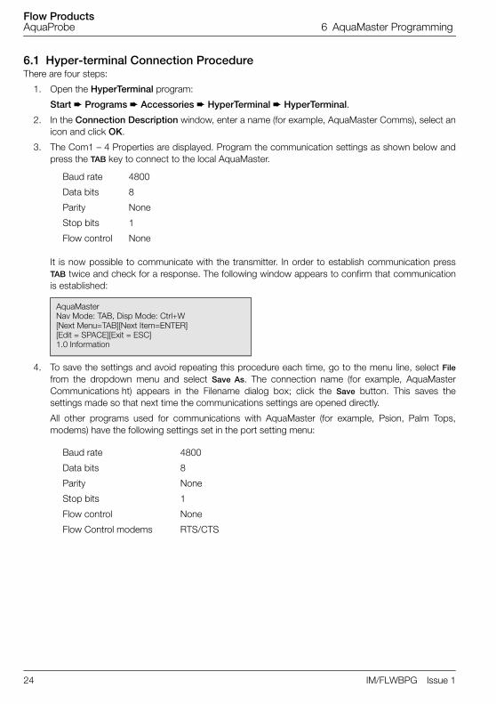
6.1 Hyper-terminal Connection ProcedureThere are four steps:
1. Open the HyperTerminal program:
Start Programs Accessories HyperTerminal HyperTerminal.
2. In the Connection Description window, enter a name (for example, AquaMaster Comms), select anicon and click OK.
3. The Com1 – 4 Properties are displayed. Program the communication settings as shown below andpress the TAB key to connect to the local AquaMaster.
It is now possible to communicate with the transmitter. In order to establish communication pressTAB twice and check for a response. The following window appears to confirm that communicationis established:
4. To save the settings and avoid repeating this procedure each time, go to the menu line, select Filefrom the dropdown menu and select Save As. The connection name (for example, AquaMasterCommunications ht) appears in the Filename dialog box; click the Save button. This saves thesettings made so that next time the communications settings are opened directly.
All other programs used for communications with AquaMaster (for example, Psion, Palm Tops,modems) have the following settings set in the port setting menu:
Baud rate 4800
Data bits 8
Parity None
Stop bits 1
Flow control None
AquaMasterNav Mode: TAB, Disp Mode: Ctrl+W[Next Menu=TAB][Next Item=ENTER][Edit = SPACE][Exit = ESC]1.0 Information
Baud rate 4800
Data bits 8
Parity None
Stop bits 1
Flow control None
Flow Control modems RTS/CTS

Flow ProductsAquaProbe 6 AquaMaster Programming
IM/FLWBPG Issue 1 25
All analog modems ≥V.32 are compatible with AquaMaster local or remote RS232 communication ports(irrespective of the compression/modulation rate) providing the modem can be restricted to the followingport settings: 4800 bps, 8 databits, parity None, 1 stop bit, hardware flow control CTS/RTS.
6.2 Setting up the Modem (Initializing)Before the modem software dials a phone number. it initializes the modem by sending it a series (string) ofcommands, typically Hayes commands. These commands configure the modem's options such as baudrate (bits per second), data compression, flow control and many other parameters. The modem manuallists the Hayes commands that the modem recognizes and the effect each command has.
6.2.1 General Connection Strings for AquaMasterV.32 – V.32bis Data Compression = ATF6;ATSØ=1;AT\Q3; AT&WØ
≥V.34 Data Compression = ATF6;ATN1;AT&K6; AT&WØ
AquaMaster (DTE)
Modem (DCE) Plug Terminal/PC (DTE) Socket
Name DB9 DB25 Name DB9 DB25
RXD RXD 2 3 TXD 3 2
TXD TXD 3 2 RXD 2 3
RTS RTS 7 4 CTS 8 5
CTS CTS 8 5 RTS 7 4
RI RI 9 22 – NC NC
GND GND 5 7 GND 5 7
Table 6.1 Port Settings
Command line for V.32 Data
Compression
Command line for ≥V.34 Data
CompressionDescription
ATF6 ATF6 Forces modem to operate in 4800 baud
ATSØ =1 ATN11 sets auto answer to one ring
(do not set to zero as this disables the auto answer facility)
AT\Q3 AT&K3 Modem uses RTS/CTS flow control
AT&WØ AT&WØStores configuration into profile 0 (zero).
Sets the power-on defaults and the ATZ recall command
ATDTn ATDTn After issuing this command, the modem attempts to establish a connection and dial the number n. Using ',' pauses for 2 seconds
+++ +++ Disconnecting. Type '+++', wait for the return prompt then type 'ATH'
Table 6.2 General Connection Strings for AquaMaster
Note. Check the user manuals for additional AT command codes. The above may vary depending onmanufacturer.

Flow ProductsAquaProbe 6 AquaMaster Programming
26 IM/FLWBPG Issue 1
6.3 Menu Structure
6.3.1 Navigation ModeEnables navigation using:
6.3.2 Command Mode Enables direct entry to menu variables
6.4 AquaMaster Passwords/Level EntryConnect the two devices together and initiate communication by pressing the TAB key several times; thefollowing screen is displayed:
Press the TAB key again to loop around the available menus (1 – 4)
1.0 Information
2.0 Measurements
3.0 Display Options
4.0 Access
Logging on to AquaMaster at either security level 2 or 4 enables write access to any variable within therelevant menu using the command mode (>) where applicable. The following menus are available:
For example, to read the flowrate via a dumb terminal connection, either enter >217 (to return>217<0>217=0.0804584) or follow the online instructions ([Next Menu = TAB] [Next Item = ] [Edit =SPACE] [Exit = ]) in menu 2 then enter into the menu and navigate down (or press to list thecontents of the menu.
Next Menu = TAB key
Next Item = ENTER key
Edit = SPACE bar
>59 0
>59 =1 (display flow YES)
AquaMasterNav Mode: TAB, Disp Mode: Ctrl+W[Next Menu=TAB][Next Item=ENTER][Edit = SPACE][Exit = ESC]1.0 Information
Free Access Level 2 (setup) Access Level 4 (am2K) Access
Menu 1 General Information
Menu 5 Flow Settings Menu 7 Outputs
Menu 2 Measurements Menu 6 Pressure Settings Menu 8 Pressure Setup (version 2 only)
Menu 3 Display Options Menu 9 Flow Calibration
Menu 4 System Access Menu 10 Tariff Settings
Menu 11 Logger Settings (version 2 only)
Menu 12 GSM Communications Settings (version 2.4x only)
Menu 13 SMS Services (version 2.4x only)
Table 6.3 Available Elements
+ "

Flow ProductsAquaProbe 6 AquaMaster Programming
IM/FLWBPG Issue 1 27
6.5 InformationThe information menu contains serial, contract and ID numbers for the flow sensor, transmitter andpressure transmitter (if supplied). It also contains calibration certificate numbers and dates. If lost passwordretrieval is required, it is necessary to supply the transmitter ID and PIN numbers.
All data is accessed via Navigation or Command mode
1.0 Information
AquaMaster
ABB Instrumentation
Stonehouse
England,UK,GL10 3TA
Tel +44 (0)1453 826661
Owner
Location
Message
: Water Company
: Larkay Road
: Secondary Sludge Outlet
Flow Sensor
I.D.
Contract
Meter Type
Cal. Date
Cert. No.
Flow Tag/Site ID
Bore (mm)
Lining
Electrodes
Flanges
Body
: 12402
: 12345/1/1
: Full-bore
: 30-10-01
: 01/007
: Waste Water
: 100
: Rubber(WRC)
: StSt
: CSt
: N/A
Pressure Sensor
I.D.
Cal. Date
Cert N°
Contract
Wetted Parts
Seals
: 12
: 30-10-01
: 007
: V/12345/2/1
: StSt
: N/A
Transmitter
I.D.
P.I.N.
Contract
Transmitter Tag
Exit
: 1014191
: 3
: V/12345/3/1
: FET/ 1234
: No

Flow ProductsAquaProbe 6 AquaMaster Programming
28 IM/FLWBPG Issue 1
6.5.1 Useful Command Mode Variable Locations
Variable Location Description
1 Sensor ID Number
17 Contract Number
28 Sensor Calibration Certificate Number
33 Site ID Number
162 Meter Owner
163 Meter Location
197 Pressure Sensor Calibration Certificate Number
207 Transmitter ID Number (required when requesting a lost password)
208 Transmitter PIN Number (required when requesting a lost password)
237 Programmed Bore/Pipe Size (mm)

Flow ProductsAquaProbe 6 AquaMaster Programming
IM/FLWBPG Issue 1 29
6.6 MeasurementsThe Measurements menu enables display of real-time flow measurement values, battery days used andelectrode signal resistances.
In this menu a test mode can be initiated that generates 1 m/s output for testing the pulse outputs.
All data is accessed via Navigation or Command mode
2.0 Measurements
Time
Date
Test Mode
Alarms
Flow
Flow %
Velocity
Pulse Output
Fwd
Rev
Net
Tariff A
Tariff B
Left Batt. (Days)
Right Batt/Mains (Days)
Prev. Left Batt. (Days)
Prev. Right Batt. (Days)
Sig A (kOhm)
Sig B (kOhm)
Exit
: 15:38:30
: 22-10-01
: Off
: Pass
: 10.2733 m^3/h
: 24.4602
: 0.161486 m/s
: 0.285369 Hz
: 578 m^3
: 0 m^3
: 578 m^3
: 378 m^3
: 200 m^3
: 0
: 266
: 0
: 0
: 3.84594
: 4.05438
: No

Flow ProductsAquaProbe 6 AquaMaster Programming
30 IM/FLWBPG Issue 1
6.6.1 Useful Command Mode Variable Locations
Variable Location Description
217 Instantaneous flowrate
219 Velocity Reading
224 Forward Totalizer
225 Reverse Totalizer
226 Net. Totalizer
231 Left Battery (Days)
232 Right Battery (Days)
233 Test Mode (1 m/s)
234 Sig A (kOhms)
235 Sig B (kOhms)
328 Sig A (Volts)
329 Sig B (Volts)

Flow ProductsAquaProbe 6 AquaMaster Programming
IM/FLWBPG Issue 1 31
6.7 Display OptionsThis menu switches on/off the functions that are viewable on the transmitter's display and/or loggeddigitally via the local communications terminal. Selecting more than one of the above options enables thedisplay to show each of the items in turn.
Selecting 1=on, 0= off
6.7.1 Useful Command Mode Variable LocationsUsing the CTRL W (Display Mode) function in a dumb terminal program such as Window's Hyper Terminalenables this data to be captured:
3.0 Display Options
Fwd
Rev
Net
Tariff A
Tariff B
Flow
Velocity
Pressure
Date/Time
Date Format
Exit
: Yes
: No
: Yes
: Yes
: Yes
: Yes
: No
: No
: Yes
: DDMMYY
: No
Variable Location Description
52 Forward Totalized Value
53 Reverse Totalized Value
55 Tariff A
56 Tariff B
59 Net Totalized Value
60 Flow Velocity
62 Date / Time

Flow ProductsAquaProbe 6 AquaMaster Programming
32 IM/FLWBPG Issue 1
6.8 AccessThe Access menu enables logon at different security levels permitting reduced access. Language change isenabled in AquaMaster S and factory download is enabled in AquaMaster.
6.8.1 Write Access Levels
Example >248=am2k returns >248=am2k<0>4 Level Logged In
6.8.2 In-built Tamper-proof SwitchThe AquaMaster is fitted with a tamper-proof switch that disables all write access to the system from theMenu Handling System. Once the tamper-proof switch is closed, it is impossible to change any of the setupparameters.
Scan reader capability (BU Metering or latest Fusion reader compatible)
6.8.3 Useful Command Mode Variable Locations
4.0 Access
Language
Login (Password)
Change Password
Current Password
New Password
Confirm New Password
No
: English
: 4 Level Logged In
: None
: **********
: ********
: ********
: Exit
Free = Menus 1 – 4 Password (none)
Level 2 = Menus 1 – 7 Password (setup)
Level 3 = Menus 1 – 7 Password (engineer)
Level 4 = Menus All Password (am2k)
Note. Using Command mode enables reading of any variable. Depending on write access level entered,writing to the variable may be restricted.
Variable Location Description
248 Login

Flow ProductsAquaProbe 6 AquaMaster Programming
IM/FLWBPG Issue 1 33
6.9 Flow SettingsWithin this menu the engineering units for URV (Upper Range Value) for flowrate, totalizer and pulsed outputconfiguration can be set.
Change the parameter by selecting it from the menu and pressing the space bar to scroll through theavailable options.
5.0 Flow Settings
Flow
FSD (100% or URV)
Zero (0% or LRV)
Cutoff (%)
Totalizer Units
Pulse Units
Pulses/Unit
Pulse Max Freq
Special Units (per m^3/s)
Special Flow Name
Special Units (per m^3)
Special Totalizer Name
Exit
: m^3/h
: 100 m^3/h
: 0
: 0
: m^3
: m^3
: 10
: 50
: 1
: m^3/s
: 1
: m^3
: No

Flow ProductsAquaProbe 6 AquaMaster Programming
34 IM/FLWBPG Issue 1
6.9.1 Engineering Units
6.9.2 Useful Command Mode Variable Locations
Default Units Totalizer Units or Pulse O/P Units
0 Special Special
1 l/s I
2 l/m M^3
3 l/h Gal
4 MLD ft^3
5 M^3/s UGal
6 M^3/m
7 M^3/h
8 M^3/d
9 Gal/s
10 Gal/m
11 Gal/h
12 MGD
13 ft^3/s
14 ft^3/m
15 ft^3/h
16 Ugal/s
17 Ugal/m
18 Ugal/h
19 MUGD
Variable Location Description
37 Totalizer units
67 Pulse Units
68 Pulses / Unit
112 Flow Units
115 URV
116 LRV

Flow ProductsAquaProbe 6 AquaMaster Programming
IM/FLWBPG Issue 1 35
6.10 Pressure Settings (AquaMaster S only)AquaMaster is fully programmable in its ability to accept different ranges and types of bridge-typetransducers (both absolute and gauge) with readout in either gauge or absolute, independent of transducertype.
When AquaMaster S is supplied with a pressure transducer, the transducer is pre-calibrated at manufactureand its calibration span and zero factors are entered into the transmitter at the factory. If for any reason thetransducer is changed, the factors for the new transducer must be entered into the transmitter using the'Pressure' setup menu 8.0.
6.10.1 Engineering Units
6.10.2 Useful Command Mode Variable Locations
6.0 Pressure Settings (AquaMaster S only)
Mode
Pressure Units
FSD (100% or URV)
Zero (0% or LRV)
Special Units (per Bar)
Special Pressure Name
Exit
: Abs
: Bar
: 16
: 0
: 1
: Bar
: No
Default Units
0 Special
1 Bar
2 mbar
3 kPa
4 mm Hg
5 mm H2O
6 Psi
7 ft H2o
Variable Location Description
66 Mode of Operation
119 Pressure Units
122 URV / 100%
123 URV / 0%

Flow ProductsAquaProbe 6 AquaMaster Programming
36 IM/FLWBPG Issue 1
6.11 Transducer Pressure Setup (AquaMaster S only)AquaMaster's flexibility of transducer types and readouts can lead to possible confusion during calibration.For this reason it is recommended that the readout is set to absolute during calibration and reset back togauge (if required) after completion, otherwise constant corrections are needed to allow for atmosphericpressure.
Set-up
1. Log in at level 4 using 'am2k'.
2. In 'Pressure Settings' menu set 'Mode' to 'Absolute' using the space bar to alternate the selection.
3. Increase damping on the pressure readout by adjusting 'Pres. Response Time' to read 10 (seconds).
To facilitate pressure readout, set all parameters in the 'Display Options' menu so that only 'Pressure'is active (set 'Pressure' to 'Yes', set all others to 'No') – see Section 6.7, page 31.
6.11.1 Changing Pressure Transducer DataThe calibration data for the transducer is recorded on a tag near the connector plug in the format –0.23/9.97, i.e. zero followed by span factor. To enter these into AquaMaster, log in at Level 4 using 'am2k' andset parameters 179 (Span factor – typical value 10) and 180 (Zero factor – typical value 0) to the correctvalues.
6.11.2 User Span and Zero Adjustment
8.0 Pressure Settings (AquaMaster S only)
Pressure FSD Bar
Mode
Offset (mm)
Pres. Response Time
Span Trim
Zero Trim
Cal. Date
Cert. No.
Factory FSD (mV/V)
Factory Zero (mV@3V)
First Fact. Cal
Last Fact. Cal.
Cert No.
Exit
: 10
: Absolute
: 0
: 3
: 1
: 0
: 30-10-01
: 007
: 10
: 0
: 12-07-01
: 12-07-01
: 01/12345
: No
Span Trim = any deviation from the calibration pressure reading. (Applied Span Pressure [in absolute] / Average Reading.)
Zero Trim = any deviation from the atmospheric pressure reading. (For example, if the readout is 1.05 bar, enter –50 into 'Zero Trim', assuming an atmospheric pressure of 1 bar.)

Flow ProductsAquaProbe 6 AquaMaster Programming
IM/FLWBPG Issue 1 37
6.12 Outputs
6.12.1 Input/Output Connections
7.0 Outputs
Output 1
Output 2
Exit
: Pulse Fwd
: Pulse Rev
: No
Caution.
Suppress or clamp inductive loads to limit voltage swings.
External isolators are not normally required as the pulse and alarm circuits are electricallyseparated from all other AquaMaster connections.
These connections are open collector, bi-polar FETs (field effect transistors).
Capacitive loads must be inrush current limited.
Fig. 6.2 Connection Diagram
MIL Spec OptionCable Part No. MVBX99147
To Datalogger,PLC etc.
5–30VDC

Flow ProductsAquaProbe 6 AquaMaster Programming
38 IM/FLWBPG Issue 1
Fully floating pulse outputs may be subject to static damage (for example, when connecting to a floatingdata logger) unless 'COM' is operated within its galvanic isolation range (±35 V) from earth. Recommendedprotection for floating output systems is to connect 'COM' to '0V'.
Maximum frequency output is 50 Hz, 10 mA @ 30 V DC.
Alarm functions on Output 3 – the following is a list of possible conditions that can result in the Outputgoing to the active state:
Battery failed (either left or right) – detected during battery check
Battery not present – detected during battery check
Sensor not connected – detected regularly during acquisition.
Coil not connected – detected regularly during acquisition
Empty Pipe Error – performed regularly by the acquisition task.
Mains Failure – detected during battery check
Sensor fault from electrode – over-voltage
The common connection for all three outputs is designated 'COM'.
6.12.2 Default Settings
6.12.3 Useful Command Mode Variable Locations
Default Output 1 Output 2 Output 3
1 On On On
2 Pulse fwd Pulse R AL–NO (normally open)
3 Pulse F + R Fwd AL–NC (normally closed)
4 Rev
Variable Location Description
70 Output 1
71 Output 2
72 Output 3

Flow ProductsAquaProbe 6 AquaMaster Programming
IM/FLWBPG Issue 1 39
6.13 Flow CalibrationThis section is for programming when using the AquaProbe 2 insertion meter with the AquaMastertransmitter. Use ABB Utilities software (or the calculations in Section 3.3 on page 14) to obtain the profilingand insertion factors.
When using AquaProbe in profiling applications the following settings are recommended to give optimumresults.
6.13.1 ProfilingAt start of profiling set:
On completion of profiling, set:
6.13.2 Default Flow Measurement Mode (Maximum Battery Life)To maximize battery life to approximately 2 years per cell, set:
9.0 Flow Calibration
Profile Factor
Insertion Factor
Probe Pipe Bore (mm)
Mode
Flow Response Time
Flow Span Trim
Flow Zero Trim (0.01mm/sec)
Cal. Date
Cert. No.
Exit
: 1
: 1
: 100
: Normal
: 3
: 1
: 0
: 30-10-01
: 01/007
: No
Empty Sensor Trip (>140) = 500
Intermittent Interval (>158=0) = 0 s
Disable Diagnostics (>321=0) = No
Time Constant (>256) = 8 s
Note. In this mode, power consumption is very high resulting in a battery life of approximately 1 monthper cell.
Intermittent Interval (>158) = 15 s (see Note below)
Disable Diagnostics (>321=1) = Yes (factory default setting)
Time Constant (>256) = 200 s
Note. Failure to set Intermittent Interval to 15 s shortens battery life to approximately 1 month per cell.
Empty Sensor Trip (>140) = 500
Intermittent Interval (>158=15) = 15 s (factory default setting)
Disable Diagnostics (>321=1) = Yes (factory default setting)
Time Constant (>256) = 8 s (factory default setting)

Flow ProductsAquaProbe 6 AquaMaster Programming
40 IM/FLWBPG Issue 1
6.14 Tariff ControlTariff information calculated by AquaMaster can de displayed in three ways; LCD display, serialcommunications interface and LogMaster.
6.14.1 LCD DisplayAquaMaster displays tariff values on an 8-digit LCD display. It is fully programmable via AquaMaster's serialinterface Display Options menu, with the facility to turn on and off the display of each tariff reading. Thedisplay is programmable such that tariffs A and B can be shown on the top line, with associated tariffannunciation A and B displayed on the lower line together with their current values.
6.14.2 Serial Communications Interface RS232Serial communication interface RS232 connection enables reading of individual totalizers and tariffs, eitherthrough the local or remote communications ports. All tariffs are displayed in the Measurement menu.
6.14.3 LogMasterTo facilitate readout of the tariff logger, known as Logger No 3, ABB's LogMaster application provides afacility to read, display and save its contents.
6.14.4 Tariff ControlControl of tariffs A and B is based on AquaMaster's real-time clock. Flexibility is offered by enabling the userto define the time of day, day of week or date during year, of switching from one tariff to another.
For example:
The Daily cycle has two time periods – Period 1(day) and Period 2 (night) – see Fig. 6.3.The Weekly cycle also has two time periods – Period 3 (weekend) and Period 4 (week) – see Fig. 6.3.The Yearly cycle also has two time periods – Period 3 (summer) and Period 4 (winter) – see Fig. 6.4.
10.0 Tariff Control
Daily Cycle Start Time
Daily Cycle End Time
Weekly Cycle Start Day
Wednesday
Yearly Cycle Start Date
Yearly Cycle End Date
Mode
Exit
: 08:00:00
: 12:00:00
: Weekly Cycle End Day
: Friday
: 01-01-01
: 01-12-01
: 2
: No
Fig. 6.3 Daily Cycle

Flow ProductsAquaProbe 6 AquaMaster Programming
IM/FLWBPG Issue 1 41
From Figs 6.3 and 6.4 there are four possible states:
Period 1 and Period 3 – Daytime during the Weekend
Period 1 and Period 4 – Daytime during the Week
Period 2 and Period 3 – Night-time during the Weekend
Period 2 and Period 4 – Night-time during the Week
By directing accumulated flow to either Tariff A or Tariff B during one or a combination of these time periods,flows can be recorded during user-defined Peak and Off-Peak times.
Fig. 6.4 Weekly Cycle
Fig. 6.5 Yearly Cycle

Flow ProductsAquaProbe 6 AquaMaster Programming
42 IM/FLWBPG Issue 1
Typically, Peak time is Daytime during the Week. From the tables above, Tariff A, Mode 2 provides flowaccumulated during the Daytime during the Week (Peak), and Tariff B, Mode 2 provides flow accumulatedduring Night-time during the Week and Daytime and Night-time during the Weekend (Off Peak).
Alternatively, a Daily-only Peak/Off-Peak cycle is achieved by selecting Mode 3. Tariff A then provides flowaccumulated during the Daytime (Peak) and Tariff B provides flow accumulated during the Night-time (Off-Peak).
A Weekly-only Peak/Off-Peak cycle is achieved by selecting Mode 5. Tariff A now provides flowaccumulated during the Weekend (Off-Peak) and Tariff B provides flow accumulated during theWeek (Peak).
As the start and end times during the daily cycle, together with the start day and end day in the Weeklycycle are user-selectable, time periods other than Day/Night and Week/Weekend can be achieved.
Tariff A Time Period
Daily Cycle 2 2 1 1
Weekly Cycle 4 3 4 3
Mode Description
OFF OFF OFF ON 1 Daytime during Weekend
OFF OFF ON OFF 2 Daytime during Week
OFF OFF ON ON 3 All Daytimes
OFF ON OFF OFF 4 Night-time during Weekend
OFF ON OFF ON 5 Daytime and Night-time during Weekends
OFF ON ON OFF 6 Daytime during Week and Night-time during Weekend
OFF ON ON ON 7 All Daytime and Weekend Night-times
Tariff B Time Period
Daily Cycle 2 2 1 1
Weekly Cycle 4 3 4 3
Mode Description
ON ON ON OFF 1 Night-time during Weekend and Daytime and Night-time during Week
ON ON OFF ON 2 Night-time during Week and Daytime and Night-time during Weekend
ON ON OFF OFF 3 All Night-times
ON OFF ON ON 4 Daytime during Weekends and Daytime and Night-time during Week
ON OFF ON OFF 5 Daytime and Night-time during Week
ON OFF OFF ON 6 Night-time during Week and Daytime during Weekend
OFF ON ON ON 7 All Daytime and Weekend Night-times
Note. ON indicates that accumulated flow is directed to the indicated tariff.

Flow ProductsAquaProbe 6 AquaMaster Programming
IM/FLWBPG Issue 1 43
Alternatively, a Yearly cycle can be combined with the Daily cycle. For the Yearly cycle there are fourpossible states:
Period 1 and Period 3 – Daytime during the Summer
Period 1 and Period 4 – Daytime during the Winter
Period 2 and Period 3 – Night-time during the Summer
Period 2 and Period 4 – Night-time during the Winter
By directing accumulated flow to either Tariff A or Tariff B during one or a combination of these time periods,flows can be recorded during user-defined Peak and Off-Peak times.
In this mode Peak time is typically Daytime during the Summer.
From the tables above, Tariff A Mode 1 provides flow accumulated during the Daytime during the Summer(Peak) and Tariff B Mode 1 provides flow accumulated during Night-time during Summer and Daytime andNight-time during the Winter (Off-Peak).
Tariff A Time Period
Daily Cycle 2 2 1 1
Yearly Cycle 4 3 4 3
Mode Description
OFF OFF OFF ON 1 Daytime during Summer
OFF OFF ON OFF 2 Daytime during Winter
OFF OFF ON ON 3 All Daytimes
OFF ON OFF OFF 4 Night-time during Summer
OFF ON OFF ON 5 Daytime and Night-time during Summer
OFF ON ON OFF 6 Daytime during Winter and Night-time during Summer
OFF ON ON ON 7 All Daytime and Summer Night-times
Tariff B Time Period
Daily Cycle 2 2 1 1
Yearly Cycle 4 3 4 3
Mode Description
ON ON ON OFF 1 Night-time during Summer and Daytime and Night-time during Winter
ON ON OFF ON 2 Night-time during Winter and Daytime and Night-time during Summer
ON ON OFF OFF 3 All Night-times
ON OFF ON ON 4 Daytime during Summer and Daytime and Night-time during Winter
ON OFF ON OFF 5 Daytime and Night-time during Winter
ON OFF OFF ON 6 Night-time during Winter and Daytime during Summer
ON OFF OFF OFF 7 Night-times during Winter

Flow ProductsAquaProbe 6 AquaMaster Programming
44 IM/FLWBPG Issue 1
Alternatively, a daily only Peak/Off-Peak cycle is achieved by selecting Mode 3. Tariff A then provides flowaccumulated during the Daytime (Peak) and Tariff B provides flow accumulated during the Night (Off-Peak).
A Yearly-only Peak/Off Peak cycle is achieved by selecting Mode 5. Tariff A now provides flow accumulatedduring the Summer (Peak) and Tariff B provides flow accumulated during the Winter (Off-Peak).
As the start and end times during the Daily cycle, together with the start date and end date in the Yearlycycle are user-selectable, time periods other than Day/Night and Winter/Summer can be achieved.
Tariff control is set-up using Tariff menu 10.0 in AquaMaster's menu structure.
Note.
Either the Weekly cycle or the Yearly cycle can be selected, but not both together. If, for example,both Yearly cycle start and end date and Weekly cycle start and end day are selected, the Weeklycycle takes priority. To enable the Yearly cycle, set the Weekly cycle start and end day to 'None'.
Switching based on day and date is fixed and is performed at midnight.
Daily cycle start and end times relate to Time Period 1
Weekly and Yearly cycle start and end times relate to Time Period 3
Yearly cycle start and end dates are entered in the format as defined in the Display Options menuitem 'Date Format' and can be DDMMYY, YYMMDD or MMDDYY.
When entering Yearly cycle start and end dates, the year is used to check for a valid entered date.Once entered, switching is based only on day and month. If, for example, 29th Feb 2000 isentered (which is a valid leap year date) then, in a subsequent non leap year, switching takesplace at midnight on 28th February.

Flow ProductsAquaProbe 6 AquaMaster Programming
IM/FLWBPG Issue 1 45
6.15 Logger AquaMaster is equipped with three loggers.
Loggers 1 and 2 are flow and pressure loggers, Logger 3 is able to hold 366 records and records theFORWARD, REVERSE, NET totalizer values for Tariffs A and B at midnight (not adjustable), together with adate and time stamp. ABB LogMaster software is required to convert Logger 3 data.
Logger 1 is usually set to record flow and pressure every 900 s (15 m), holding a maximum of 8,831 records(3 months capacity).
Logger 2 is usually set to record flow and pressure every 60 s, holding a maximum of 11,361 records(capacity at this time interval is just over 7 days).
The time intervals of the loggers are set using:
Parameter 166 for logger 1
Parameter 168 for logger 2
Parameters 166 and 168 are user-configurable (note that both the time intervals must be set in seconds tobetween 15 – 65500)
Parameter 151 enables coded options to be selected for different commercial software:
1 = ABB (LogMaster)
2 = BVS (OSI PI Database / BVS_Wadis System)
3 = Technolog (PMAC)
4 = Primayer (Primeware)
7 = For SMS logger function
Hardware, Software requirement:
PC with Windows 98, NT
WEBC 2000 communication lead
LogMaster software for local data retrieval
Commercial software for remote data retrieval
11.0 Logger
Logger 1 Interval (s)
Logger 2 Interval (s)
Exit
: 900
: 60
: No
Variable Location Description
166 Logger 1
168 Logger 2
Note. Menus 12 and 13 are applicable only to GSM/SMS transmitter units.

Flow ProductsAquaProbe 6 AquaMaster Programming
46 IM/FLWBPG Issue 1
6.16 GSM Communications Settings (v2.4x Software)
6.16.1 Commissioning – Signal Strength TestThis performs a radio signal test for selecting the optimum location for the antenna. The system can betested in its final commissioned location and state (for example, manhole cover closed and any localcommunications equipment disconnected from the meter). Menu 12 controls the GSM features. Navigateto Menu 12 and select the Signal Test Wait Time [>354]. Enter the time (in seconds) that the system waitsbefore starting the signal test. A count-down starts from the selected Wait Time to zero and is shown onthe LCD display. At this point, close up the installation into its commissioned state. When the count reacheszero, a radio signal strength measurement is taken and the result is shown on the display for 30 seconds(long enough to open the door or meter cover to inspect the result). The strongest signal strength isrepresented by a value of 31; the weakest is a value below 5.
6.16.2 SIM NumbersData-enabled SIMs sometimes have both a Voice telephone number and a Data telephone number. In suchcases, use the Voice number for remote access via SMS text; use the Data number for remote dial-upoperation, for example, using LogMaster.
12.0 GSM Communications Settings
GSM Module Status
SIM Access Lock
SIM ID Number
SIM Password
Network
Signal Log (new –> old)
Total Connect Time
Signal Test Wait Time(s)
Manual GSM Session
: Connected
: Lock Disabled
: 8997401002011884582
: 7783
: ANY COUNTRY MOBILE
: 22 15 22 22 9
: 0:02:00
: 0
: Trigger
Periodic Wakeup Settings
WakeUp Base Time
WakeUp Base Day
WakeUp Schedule
WakeUp Duration
: 14:00
: Wednesday
: 1 day
: 15
Flow ProductsAquaProbe 6 AquaMaster Programming
IM/FLWBPG Issue 1 47
6.16.3 GSM WakeUp ControlBattery-Powered Meters
To conserve battery power, the GSM radio module is normally powered down. To operate remotecommunications (SMS Requests, Auto Report or Remote Dial Up), the GSM radio module can be wokeneither by selecting Menu 12 and requesting a Manual Wakeup [>358=1] – which forces the module to wakeup for the WakeUp Duration [>352] – or by setting a programmable WakeUp schedule. The WakeUpSchedule [>353] can be programmed for wakeups every 12 hours, 1 day or Always Off. The Base Time[>351] sets the time of day for the WakeUp Duration.
The power supply to the transmitter can be ordered as one of the following types:
Mains with battery-powered backup
Battery only (dual internal cells)
External battery pack with backup
For mains-powered units with battery-powered backup, the WakeUp Duration does not apply as the GSMmodule is either powered continuously (whilst there is mains power present) or not powered (whilst onbackup battery). For battery-only meters powered either by 2 internal cells or by an external battery pack,the WakeUp Duration (>352) has a range of 3 to 23 minutes
GSM Module Status
GSM Module Status [>368] shows the current GSM radio module status as one of the following:
Signal Strength (current value)
The Signal Strength parameter [>348] is used to obtain the radio signal strength on demand – for example,>348<0>=16.
6.16.4 Access via SMS Text MessageA transmitter with the GSM option also provides a means of accessing AquaMaster data via SMS textmessaging. An SMS Request Text can be sent from a mobile phone to AquaMaster and an SMS Reply Textwith the requested information is sent to the originating phone or SMS gateway. If the AquaMaster isbattery-powered, the SMS Request is not performed until the next programmed WakeUp time as defined inMenu 13.
0 = Not Configured
1 = Off
2 = Off (SIM not fitted)
3 = Ready
4 = Waiting PIN
5 = Waiting PUK
6 = Waiting Antitheft PIN
7 = Waiting Antitheft PUK
8 = Waiting PIN2
9 = Waiting PUK2
10 = SMS Mode
11 = Command Handling
12 = Connecting
13 = Connected

Flow ProductsAquaProbe 6 AquaMaster Programming
48 IM/FLWBPG Issue 1
6.16.5 SMS Request Message SMS Request messages must have the following format: +password;command;command;...;command;Where: +password is the character '+' followed by the AquaMaster login password [>248] and thecommand may be:
Any of the AquaMaster Parameter Access commands:
– FLW (Rate Of Flow), VEL (Rate Of Velocity), PRS (Pressure), ALM (Alarm), TOF (Total VolumeForward), TOR (Total Volume Reverse), TON (Total Volume Net), TFA (Tariff A), TFB (Tariff B),(TIM) Time and Date – or any regular Command Line Interface requests
Or any regular Command Line Interface requests
For example: >365 to show the last 7 signal strength readings.
Sending:
+user;FLW;PRS;TOF;TFA;TIM;>365;
results in a reply similar to:
-AquaMaster;ABB01M; Flow=-157.93 Vs;Pressure=-0.619765 Bar; TOT Fwd=16853 m3;TRF A=1966 m3; TIME=00:00:01 08-07 -03;<0>365=14 14 14 13 12 14 14;
Variable Location Description
354 Signal Test Time Wait
358 Manual GSM Session

Flow ProductsAquaProbe 6 AquaMaster Programming
IM/FLWBPG Issue 1 49
6.17 SMS Services
13.0 SMS Services
Auto Report Phone No. 1
Auto Report Phone No. 2
Auto Report Phone No. 3
: +447999172112 (Server)
: 9245551116 (Owners Mobile)
: 447711141667 (ABB service or Owners Mobile)
Text Auto-Reports
Destination
Text Report Schedule
Command String
: Phone No. 1
: Weekly [set 5]
: FLW;TOF;ALM
Flow / Pressure Log Auto-Reports
Destination
Flow Report Schedule
Flow Report Units
Pressure Report Schedule
Pressure Report Units
: Phone No. 2
: Daily [4]
: m^3/h
: 0]Off
: Bar
Totalizer Auto-Reports
Destination
Totalizer Report Schedule
: Phone No. 1
: Daily
Alarm Auto-Reports
Destination
Alarm Reports Enabled
Exit
: Phone No. 3
: Yes
: No

Flow ProductsAquaProbe 6 AquaMaster Programming
50 IM/FLWBPG Issue 1
The following lists of variables are important for setup and operation of an AquaMaster with the SMSLogger Server. Some of these are preset at the factory; the remainder require setting only if the specificfunction is required.
Most of the variables associated with GSM/SMS are in the Menu Handling System (MHS) on menus 12 and13, or can be accessed via their variable number.
Factory settings require access levels 5 or above, so cannot be changed by the user at normal login accesslevels. Contact your local ABB distributor for a one-time access code if a factory setting is incorrect andneeds changing.The variables in the right-hand column in the above table are the key variable valuesrequired when using AquaMaster SMS server software.
Variable Location Description
33 User-defined string for Site ID. This must be unique when using with SMS Logger Server.
151 7
164 1
165 1
253 Time
254 Date
290 0
334 0
335 0
371 1
401 1
405 0
406 1
Table 6.4 List of Variables
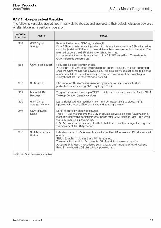
Flow ProductsAquaProbe 6 AquaMaster Programming
IM/FLWBPG Issue 1 51
6.17.1 Non-persistent VariablesThe following variables are not held in non-volatile storage and are reset to their default values on power-upor after triggering a particular operation.
VariableLocation Name Notes
348 GSM Signal Strength
Returns the last read GSM signal strength. If the GSM engine is on, writing value 1 to this location causes the GSM information variables (variables 348, etc.) to be updated (which takes a couple of seconds). The returned value is the GSM signal strength at this time.It is updated automatically one minute after GSM Wakeup Base Time when the GSM module is powered-up.
354 GSM Test Request Requests a signal strength check. Value (from 0 to 255) is the time in seconds before the signal check is performed once the GSM module has powered-up. This time allows cabinet doors to be shut or chamber lids to be replaced to give a better impression of the actual signal strength that the unit receives once installed.
357 SIM Card ID ID number of SIM (sometimes needed by service providers for verification, particularly for unblocking SIMs requiring a PUK).
358 Manual GSM Request
Triggers immediate power-up of GSM module and maintains power on for the GSM Wakeup Duration (sensor variable).
365 GSM Signal Strength History
Last 7 signal strength readings shown in order newest (left) to oldest (right).Updated whenever a GSM signal strength reading is made.
366 GSM Network Name
Name of currently-acquired network. This is '–' until the first time the GSM module is powered-up after AquaMaster is reset. It is updated automatically one minute after GSM Wakeup Base Time when the GSM module is powered-up.If 'No Network Name' is shown it is likely that there is insufficient signal strength for the network of the SIM provider.
367 SIM Access Lock Status
Indicates status of SIM Access Lock (whether the SIM requires a PIN to be entered or not). Status 'Enabled' indicates that a PIN is required.The status is '–' until the first time the GSM module is powered-up after AquaMaster is reset. It is updated automatically one minute after GSM Wakeup Base Time when the GSM module is powered-up.
Table 6.5 Non-persistent Variables

Flow ProductsAquaProbe 6 AquaMaster Programming
52 IM/FLWBPG Issue 1
6.17.2 Persistent Variables Stored in AquaMaster Transmitter
VariableLocation Name Notes
151 Logger Supplier Code Factory setting. Must have value 7 for use with SMS Logger Server.
253 Time AquaMaster current time.
254 Date AquaMaster current date.
319 Transmitter Power Type
Factory setting. Describes power supply type that AquaMaster transmitter expects:0 = dual D-cell battery supply (standard units)1 = mains power with D-cell backup battery (standard units)2 = external battery pack with backup battery (Explorer units)3 = solar power with backup battery (Explorer units)AquaMaster resets automatically if this variable is changed.
355 SIM Password Password (PIN) for SIM. Applied if AquaMaster detects that GSM module's SIM access lock is enabled. If the SIM does not require a PIN for access then this may be set to '–'.
371 Remote Communications Function
Defines the type of remote communications that AquaMaster is configured to use.
This is set at the factory before shipment.
Must be set to 'GSM modem' (value 1) for GSM / SMS communications to work.
Login to user access level 4 to change this variable.AquaMaster automatically resets if this variable is changed.
406 SMS Log Reports Enabled Factory setting. Must be set to 'Enabled' (value 1) for SMS log reports to be sent.
Table 6.6 Persistent Variables Stored in AquaMaster Transmitter

Flow ProductsAquaProbe 6 AquaMaster Programming
IM/FLWBPG Issue 1 53
6.17.3 Persistent Variables Stored in AquaMaster SensorAll of the sensor variables in Table 6.7 are accessible at login level 4. Note that sensor variables can bechanged only when the AquaMaster transmitter is connected to the sensor.
VariableLocation Name Notes
33 Meter ID User-defined string for meter (sensor) ID. This must be unique when using with SMS Logger Server.
347 Wakeup Base Day Day of week that weekly reports are sent on.
351 Wakeup Base Time Time of day for GSM wakeups. Also time that reports are sent at.
352 Wakeup Duration Duration that GSM module is kept on for at each wakeup time.
353 Wakeup Interval Period between GSM module wakeups (off,12 hr, 24 hrs).
361 MPAP Text Report Schedule Specifies schedule for text reports in MPAP format.
362 Phone Number 1 Phone number to send reports to.
363 MPAP Text Report Commands
A string of MPAP command mnemonics that are the basis for MPAP format text reports.
382 Phone Number 2 Phone number to send reports to.
385 Flow Report Units Specifies the units that flow logger data reports are in.
386 Pressure Report Units Specifies the units that pressure logger data reports are in.
388 Flow Report Schedule Specifies schedule for flow reports. Either off (0) or daily (1).
389 Pressure Report Schedule Specifies schedule for pressure reports. Either off (0) or daily (1).
391 Phone Number 3 Phone number to send reports to.
394 MPAP Text Auto-Report Phone Selection
Specifies to which phone number MPAP text auto-reports are sent (value 0 = phone number 1, 1 = phone number 2, 2 = phone number 3).
395 Flow / Pressure Auto-Report Phone Selection
Specifies to which phone number flow and pressure auto-reports are sent.
399 Totalizer Report Schedule
Specifies schedule for totalizer reports. Either off, Daily, Weekly (on WakeUp Base Day) or Monthly (on first day of month).
400 Totalizer Auto-Report Phone Selection
Specifies to which phone number totalizer auto-reports are sent.
401 Alarm Auto-Report Phone Selection Specifies to which phone number alarm reports are sent.
402 Alarm Reports Enabled
Specifies whether automatic alarm reports are enabled or not. Alarm reports are sent on detection of sensor or power supply problems.
Table 6.7 Persistent Variables Stored in AquaMaster Sensor

Flow ProductsAquaProbe 7 SMS Logger Server Software
54 IM/FLWBPG Issue 1
7 SMS Logger Server Software The server application runs in conjunction with a gateway application that manages the actualcommunications between PC and GSM module. Details of the setup for the SMS Gateway are in its UserManual.
The SMS Gateway is an application that manages the actual communications between the PC and theGSM module. The AquaMaster SMS Logger Server application is used with one of two gateways:
GPA SMS Gateway
AMI SMS Gateway (by AMI India)
Currently, only the GPA SMS Gateway is available for use, so the following notes do not cover the AMI SMSGateway. Consequently, the help notes in the SMS Logger Server documentation refer to setup of the GPASMS Gateway only, but will be extended to include details for the AMI SMS Gateway when this optionbecomes available.
Ensure that the following Windows components are installed on the PC before the SMS Logger Serversoftware is installed:
Internet Information Services (IIS) version 5.0 – on Windows installation CD
Microsoft Message Queueing (MSMQ) – on Windows installation CD
Microsoft.NET framework version 1.1 – included in email of SMS Logger Server files (or can bedownloaded [23 Mb] from MS website)
Fig. 7.1 SMS Gateway – Overview
%/%012
%/%%)
"#
"&3'

Flow ProductsAquaProbe 7 SMS Logger Server Software
IM/FLWBPG Issue 1 55
7.1 Installing SMS Logger Server Software This section describes how to set up an AquaMaster to power its internal GSM module periodically, readyto accept dial-up connections or respond to text messages in MPAP format.
1. Check that the AquaMaster transmitter power type is set correctly (transmitter variable 319). This isset at the factory, but is important as it determines how the AquaMaster's GSM module is powered.This is a factory setting that requires a level 5 access code to change it if not set correctly. When it ischanged the AquaMaster immediately reboots automatically.
2. Check that the Remote Communications Function is set for 'GSM Modem' (transmitter variable 371).This is set at the factory but, if it is incorrect, the GSM module cannot be used. This is accessed ataccess level 4 and the AquaMaster immediately reboots automatically if it is changed.
3. Set AquaMaster time and date (transmitter variables 253 and 254) to correct time. Note that in timezones where there is a standard (Winter) and daylight (Summer) time the AquaMaster is set forstandard time throughout the year.
4. Set up SIM Password (transmitter variable 355) if SIM access lock is enabled. The password is thePIN number that AquaMaster must use to access the SIM each time its GSM module is powered-upand only if the access lock is enabled. The PIN number and the access lock setting are properties ofthe SIM itself, so the AquaMaster SIM Password must be reviewed whenever a new SIM is inserted.
5. Set up to three report destination phone numbers (sensor variables 362, 382 and 391). These phonenumber slots enable reports to be sent to various destinations, for example, MPAP reports to phonenumber 1; flow, pressure and totalizer reports to phone number 2; alarm reports to phone number 3.
6. For text-based MPAP reports, set the appropriate destination phone number slot (sensor variable394).
7. Set the MPAP report schedule as appropriate (sensor variable 361). If no MPAP reports are required,set schedule to 'Off' (value 0). Note that schedules for 30 minutes, 1 hour and 2 hours work only withmains-powered units. The setting is treated as 'Off' for battery-powered units.
8. A signal test can be performed that enables the GSM module to be triggered (variable 354) and thenread the GSM network carrier signal quality after a settable time period (to allow time for covers ordoors to be closed in AquaMaster mounting chamber or cabinet).
9. Test power-up settings by setting WakeUp Base Time (sensor variable 351) to the near future (e.g.current time plus 2 minutes) and wait for the GSM module to power-up. If MPAP reports arescheduled for 'Daily', a report is also sent at this time to the selected phone number. Can also dial-up while the GSM module is powered-up to check connection (provided SIM is data-enabled).
10. Set WakeUp Base Time (sensor variable 351) to actual required report time.
Continued...

Flow ProductsAquaProbe 7 SMS Logger Server Software
56 IM/FLWBPG Issue 1
11. Set WakeUp Duration (sensor variable 352) to required GSM power-on duration.
12. Set the WakeUp Base Day (sensor variable 347) to the day on which the weekly reports are required.If report schedules do not have a weekly report this setting is not required.
Note. The length of this time affects battery life. For systems used primarily for sending SMS messages, the duration can be short (for example 3 minutes), but to allow reliable synchronization for dial-up connections a longer WakeUp Duration may be needed (for example, 5 to 10 minutes)
Fig. 7.2 WakeUp Base Day Duration
, "- , "-, "-
%/%4'%
/5
(5'6-7.
(5&5/5'-7.
6
0%/ 15
0%/ 1&1
)3,5#5#'8'%/%95'')25'

Flow ProductsAquaProbe 7 SMS Logger Server Software
IM/FLWBPG Issue 1 57
7.2 AquaMaster Setup for Logger Messages via SMSThis requires that the setup for GSM has been performed previously.
1. Check that the Logger Supplier Code (transmitter variable) is set to value 7, or else the SMS LoggerServer does not decode logger reports from this AquaMaster. This is a factory setting that requires alevel 7 access code to change it if not set to value 7, and this may require the purchase of a newlicense if the meter was not ordered for use with the ABB SMS Logger Server.
2. Check that SMS Logger Reports are enabled (transmitter variable). This is a factory setting that has avalue of 1 (enabled) and needs a level 5 access code if it is not set correctly. Only text-based MPAPreports can be sent via SMS if this parameter is set to 0 (disabled).
3. Ensure that the meter ID (sensor variable) is unique compared to all other meters configured to reportto the SMS Logger Server and change accordingly if not.
4. Set the phone number selection for each report type (sensor variables, and for MPAP, flow/pressure,totalizer and alarm report destinations). The same phone number selection can be used for differentreports. However, the receiving end may not be able to understand the message, e.g., an SMSLogger Server can understand flow record, pressure record, totalizer, alarm reports plus some MPAPreports such as DIB reports; flow record, pressure record and totalizer reports are in a binary form socannot be displayed in a meaningful way on anything other than the SMS Logger Server.
5. Set the schedules for the logger reports as needed (sensor variables, etc.) and turn MPAP reports offif no longer required by setting MPAP report schedule (sensor variable) to 'Off' (value 1).
6. Flow and pressure logger reports have their record data expressed in terms of settable units (sensorvariables etc.).

Flow ProductsAquaProbe 7 SMS Logger Server Software
58 IM/FLWBPG Issue 1
Menu display Var ID Explanation of settings shown
13.0 SMS Services
Auto Report Phone No. 1 : 09977123456Auto Report Phone No. 2 : 09977678912Auto Report Phone No. 3 : –
362382391
Two phone numbers defined for SMS report destinations. Third number left undefined.
Text Auto-Reports
Destination : Phone No. 1Text Report Schedule : OffCommand String : FLW;PRS;TOF;ALM;
394361363
Any text reports are sent to phone number 1, that is, 09977123456.Schedule is for no text reports.
Flow / Pressure Log Auto-Reports
Destination : Phone No. 2Flow Report Schedule : DailyFlow Report Units : l/sPressure Report Schedule : DailyPressure Report Units : Bar
395388385389386
Any flow or pressure reports are sent to phone number 2, Schedule is for daily flow reports in l/s and daily pressure reports in bar.
Totalizer Auto-Reports
Destination : Phone No. 2Totalizer Report Schedule : Weekly
400399
Any totalizer reports are sent to phone number 2, Schedule is for weekly totalizer reports, which are on day specified by Wakeup Base Day, var 347.
Alarm Auto-Reports
Destination : Phone No. 1Alarm Reports Enabled : Yes
401402
Automatic alarm reports, for sensor or power supply problems, are enabled and are sent to phone number 1
Table 7.1 AquaMaster Setup for Logger Messages via SMS

Flow ProductsAquaProbe 8 MagMaster Programming and Menu Structure
IM/FLWBPG Issue 1 59
8 MagMaster Programming and Menu Structure Initially, connect the serial communication port of the device you are using to the serial port of theMagMaster either through the nine-pin D plug on the unit or hard wire into the terminals provided within theterminal enclosure.
The communications port must be set to:
The method of doing this varies depending on the device being used.
These settings are covered in the Manual [Book 4 Operation]
If using a PC or laptop then any standard communications package can be used, such as WindowsTerminal, PCTools, Procom or any similar package.
Most options available are covered in the manual as a means of setting-up. If problems are experiencedwith any other device, assistance can be requested from the Company. Please note that there is no specialsoftware requirement in any device other than the standard communications package as all necessarydedicated software is contained within the MagMaster itself.
Having connected the two devices together and initiated communication, a message appears on thescreen (MagMaster) with a version number of the software the system is running. Pressing brings thefirst line of the menu on the screen in the form:
Read 1 >
All menu items on the MagMaster system appear on the screen as a word, a number and >. To move to asub-menu level from here, or to change the value (if appropriate) within the menu item the number to the leftof the cursor needs to be entered such that the sub-menu is displayed (or the variable to be changed).
The entry is repeated, this time with a question mark. When the question mark is on screen the value maybe changed. The menu system is explained below.
The first item on the main menu is:
Baud rate 4800
Data bits 8
Parity None
Stop bits 1
Flow control None
Flow control modem X0n/XOff (hand 0 / protocol 0)
Menu Item Description
Read 1> The submenu items are listed in the manual showing the items that can be read.
To enter this menu, press the number to the left of the cursor (1) and then press .
Read Flow 1> 9999 This is the instantaneous live flow rate, in the engineering units selected.
Press to scroll through the menu.
Read %2> 85 This is the percentage that the instantaneous flow is of the full scale flow selected.
Press .
Read Forward 3> 123456 This is the forward total flow since the system was reset or powered-up initially.
Press .
Read Rev 4 > 222222 This is the reverse total flow.
Press .
Read net 5 > 98766 This is the net total (or the difference between the forward and reverse flows).
Press .

Flow ProductsAquaProbe 8 MagMaster Programming and Menu Structure
60 IM/FLWBPG Issue 1
Read alarm 6 > This is the alarm status. It may show 'clr' (clear) or it may give the alarm condition, scrolling through the differing alarm conditions if more than one is current.
Press .
Read Vel 7> This is the velocity in metres per second or feet per second (for USA).
Press .
Read quit Q> This is the end of the menu.
Press then to return to the main menu, or press to return to the first item on this menu.
Read flow 1 > This menu is a remote reproduction of the information available on the front display of the unit (if one is fitted) and is a 'reading' menu not a 'changing' menu.
No password is required to access the information.
Press then to return to the main menu or press to move to the second item on the menu.
Disp 2>. Display 2 is the second item on the menu.
To access this sub-menu to control the display, press then .
Disp mode 1 > and a number.
This number can be 0, 1 or 2 and controls the mode of the display of the communicating equipment (PC, Psion organizer etc.). With mode 0 the '0' is displayed on the same line.
Disp Mode 1>0 In display mode 1 the value is displayed on the second line, subsequent to the menu item.
Disp Mode 1>1 In display mode 2 the value is displayed on the line subsequent to the menu item and then, every time it is updated (every second) it is put upon a new line.
This is particularly useful for direct printing of values or, more importantly, for data logging.
To change the mode, enter the number to the left of the cursor arrow 1 and press .
The menu item appears again, as before, but this time with a question mark.
Disp Mode 1> 0? Because the question mark is now on screen, the mode can now be changed.
Enter 0, 1 or 2, as required.
Press .
Disp Res 2>2 This is the display resolution.
The number of decimal places may be selected using the hand-held terminal and shown on the local display, if fitted, or transmitted to any remote device connected by serial linkage.
Here there are 2 decimal places selected.
To change this, enter the number to the left of the cursor (2) and press .
The line is repeated again with a question mark …
Disp Res 2>2? … now a different number of decimal places on the display can be entered.
Press .
Menu Item Description
.
.

Flow ProductsAquaProbe 8 MagMaster Programming and Menu Structure
IM/FLWBPG Issue 1 61
Disp quit Q> This is the end of the menu.
Press then to return to the main menu, or press to return to the first item on this menu.
So far there have been two menus that permit viewing of the information and changing of the way in which the information is displayed. It is reasonable to have both menus available to all with authority to view the meter and therefore there is no password protection at this level. However, to proceed further into the menus a password is required.
There are two levels of protection and two passwords to gain access to these levels; one intended for the operator, or user, and one intended for the instrument engineer. These two passwords are set in the factory as 'user' and 'engineer' both in lower case and can be changed as required. If a password is changed, it is important to remember it as there is no simple way to reinstate the originals. The passwords are the only way to get into the system.
To sign-on as a user, press – Login 3 > is displayed.
Select the login sub-menu by pressing then .
The first response is:
Login en 1> 0 Zero (0) – access denied (no password entered).
To enter a password, in the same way as changing a value, select the number to the left of the cursor 1 and press .
The message is repeated with a question mark.
Login en 1> 0? the MagMaster is now in a position to accept a password.
Type 'user0' (in lower case letters).
The response is:
Login en 1> 1 The User is now logged-in at level 1. For the purposes of this training, login again as an engineer, to give us access to all levels. Those items that are not available to the User are identified later. To login again we enter the number to the left of the arrow (1).
Login en 1> 1? The question mark is displayed.
Enter the password 'engineer' (all in lower case).
Login en 1>2. Access level 2 of the programming is now permitted.
Press .
Login key 2> Press again.
Login key 3>. These two items are the menu entries for changing the passwords from 'user' and 'engineer' to whatever is required.
This is explained in the manuals in detail.
Press .
Login quit Q > Press then to return to the main menu.
The next item on the main menu is:
Flow 4> Setting the full scale flow range of the flowmeter and the units in which it measures.
Press then to access flow sub-menu – the first item is Flow range 1 > and then a number.
The number is the maximum flow in the units that are selected. It can be changed here to a new value.
Enter 1 (the number to the left of the arrow).
Flow range 1 > 999? When the question mark is displayed, enter the number required.
Press .
Flow unit 2>. Press then to access the flow unit menu.
Press to scroll through the available units.
Menu Item Description
.
.
/

Flow ProductsAquaProbe 8 MagMaster Programming and Menu Structure
62 IM/FLWBPG Issue 1
Flow Unit Ltr 1> (litres)
Flow Unit m^3 2> (m3)
Flow Unit gal 3> (Gallons)
Flow Unit Ugal 4> (US gallons)
Flow Unit ft^3 5> (ft3)
Flow Unit Quit Q>
Any of these units can be selected by putting a 1 against the unit required.
For example, if litres are required, press to select it.
Flow unit litre 1> 0 Press , (the number to the left of the cursor) and then .
'Flow unit litre 1> 0?' Is displayed.
Press then . Flow units are now in litres.
Press until 'Flow Unit Quit Q>' is displayed.
Press then to return to the flow sub-menu.
The next item on that menu is 'Flow mult 3>'.
Press , then to access the flow multiplier sub-menu to select a multiplier as part of the flow range. Litres is selected above.
The setting for 100's of litres per second or millilitres per second (for example) is made at this parameter.
The first item is:
Flow Mult m 1 >(milli 1/thousandth)
Flow Mult c 2 >(centi 1/hundreth)
Flow Mult 3 >(unity * 1 default Setting)
Flow Mult h 4 >(Hecta * 100)
Flow Mult k 5 >(Kilo * 1000)
Flow Mult M 6 >(Mega * 1,000,000)
To select a multiplier of 1, press then (the number to the left of the cursor) for flow multiplier 1.
Flow multiplier 3>0? Press then to select the multiplier of 1.
Press then to access the sub-menu.
Enter the time units (seconds, minutes, hours, days or weeks).
For litres per minute (for example) press then .
The display now shows:
Flow time 4> Press then to return to the flow sub-menu.
Item 4 on the menu is …
Flow time min 2> 0?
Flow mult quit Q> Press then to select it.
Press then to return to the sub-menu.
The measurement and the full scale flow range have now been entered.
The next item on the flow sub-menu is:
Menu Item Description
%
%
.
0
0
%
/
.
%
.

Flow ProductsAquaProbe 8 MagMaster Programming and Menu Structure
IM/FLWBPG Issue 1 63
Flow response 5> Set the response time of the meter.
The default value is a 3.
Press to access the next item on the menu.
Flow probe 6> This section of the menu is for use when using an insertion probe.
There are two factors required by insertion probes – the insertion factor and the profile factor.
Press then to access the flow probe part of the menu to enter the factors for the flow profile and the flow insertion. In case of a full-bore meter, which is the most common case, set both of these factors to 1.
Press then to return to the flow menu.
The next item on this menu is:
Flow%7 > 56 This is the current measured flow rate as a percentage of full scale.
This is on the menu as a means of checking that an error has not been made when setting up a flow meter.
The next item is:
Flow Cut Off 8> This the flow cut off. This is the flow velocity (in millimetres per second) below which all outputs are set to zero. For mechanical meters there is a point below which mechanical meters will not operate; due mainly to friction. When electronic meters were introduced, it was required that they imitate the mechanical meters in this failing and this is the part of the menu that enables this setting, i.e. enables the meter to stop reading (artificially) below a certain velocity.
This is the first item on the menu that requires level 2 access.
For level 1 access this item is not displayed.
Press then for access to this cut-off.
The display repeats to:
Flow Cut Off 8>2? Enter the number of millimetres per second below which the flow is cut off.
Press then to return to the main menu.
The next item on the menu is:
Anlg 5> This is the analog sub-menu.
Set the full scale value of current output, the zero value and the flow direction it responds to.
To enter this menu press (the number to the left of the arrow) then .
The first item is:
Anlg Fsd 1> 20 Usually this is set to 20, as most analog outputs are 4 to 20 mA.
Enter the high number, then press .
Anlg Zero 2> 4 Enter the low number (the default is 4).
To make this zero, press then .
Anlg Zero 2> 4? With the question mark present, press then .
4 to 20 is now changed to 0 to 20 (or any other number required).
Next item on the menu is:
Anlg Dir 3> Press then to access the sub-menu.
The first item is:
Anlg Dir Fwd 1 >
Anlg Dir Rev 2 >
If 1 is set ….
Menu Item Description
1
.
.
2
0

Flow ProductsAquaProbe 8 MagMaster Programming and Menu Structure
64 IM/FLWBPG Issue 1
Anlg Dir Fwd 1 > the meter responds, and gives an output, for flows in the forward direction.
If the second item (Anlg Dir Rev 2 >) is set to 1, the meter responds to reverse flows.
If 1 is entered against both items, the meter provides an output proportional to flows in both directions.
If zero is entered against both items, there is no current output. Be careful with this item.
Press then to return to the analog sub-menu.
The next item on the menu is the actual analog mA output (in real time). Once again this provides a check and displays the current output that the device is supplying (or trying to supply) at the moment.
If the current output circuit has not been completed the reading still provides the correct value.
Press then to return to the main menu.
Item 6 on the main menu is 'Puls 6 >'.
Press then to access the pulse menu – there are 6 items.
The first one is:
Puls Factor 1>. Enter the number that represents the required number of pulses per volume unit selected previously. For example, if litres have been selected in the flow setting-up procedure and one pulse per litre is required, set '1'. If litres have been selected, then one pulse per cubic meter or 1000 litres is required, set here one divided by 1000 which is 0.001 If 100 pulses per litre are required, set 100. This setting is just a multiplier of the units of volume.
To change the number press then . Once the question mark is displayed, enter the factor required. Item 2 is the pulse cut-off, as a % of the full scale flow.
Below this figure the pulse outputs and the totalizer, built into the display (if there is one), cease to function for reasons outlined above. If operation down to 0 flow is required, enter zero here. Item 3 on the menu is pulse maximum.
This sets the maximum frequency that the MagMaster outputs. It is normally set at 800, the maximum MagMaster can output, but if the device connected to it has a maximum input of 50 (for example), enter 50. If unsure, leave at 800.
Item 4 on the menu shows the output, this time in Hz, of the measured flow (in real time). Again, this is in the menu as a check that the other items are entered correctly. Item 5 is the pulse idle state. This sets the pulse output level in the idle state (or off state) to be set to either 0 or 1.
Enter a zero if, in the pulse idle state, the connections are open circuit; enter 1 if they are short circuit. This item requires level 2 access, as does the next one (pulse size) where the pulse width in milliseconds required to output is entered.
Enter 0 for a square wave output. Care must be exercised here not to set too wide a pulse, taking into account the number of pulses requested, as too wide a pulse at too high a frequency causes the pulses to join and no pulse output is the result.
Press then to return to the main menu.
The next item on the main menu is:
TOT 7 > This is the totalizer.
Press then to access the totalizer menu.
The first item is the totalizer units.
Press then to access the submenu for totalizer units.
In this sub-menu' totalizer units are selected as litres, cubic meters, gallons, US gallons, cubic feet – similar to the flow units selected previously. Navigate to the item required, enter the number to the left of the arrow so the question mark is displayed and then input a 1 against the value required.
For example, to totalize in US gallons, navigate to 4, press then .
The display shows:
Menu Item Description
.
.
1
%
.
3
%
/

Flow ProductsAquaProbe 8 MagMaster Programming and Menu Structure
IM/FLWBPG Issue 1 65
Tot Ugal 4 >O? Press then to select the totalizer units required (not the pulse output – just the totalizer on the display) to be US gallons.
Press to return to the totalizer sub-menu.
The next item is:
TOT MULT 2> Totalizer multiplier. As in the flow setup the totalizer unit can be multiplied by any number, 1000 ths, 100 ths, 1, 100 s thousands or millions – so there can be any combination of units or multipliers. The third item is:
TOTCLR EN 3 > This is Totalizer, Clear, Enable. Set 1 to reset the totalizer, either by means of the magnet on the front of the panel or remotely through the input terminal (if selected). This is normally set at 0 so that the totalizer cannot be reset.
The last item (Quit) returns to the main menu.
The next item on the main menu is:
Alarm 8 >. There are two alarms available on the MagMaster. Alarm no 1 and Alarm no 2.
Press then to access the alarm sub-menu.
The first item is alarm no. 1. Accessing alarm 1, the first item is 'alarm no1 idle state'. Set the idle status of the alarm, i.e. the contacts to be either open circuit or closed circuit in the idle state so that the action of the alarm can be predicted when the alarm situation occurs.
Alarm no.1 enable is the second item and advises if this alarm is used.
To use the alarm, enable it by entering a 1.
So to enable this alarm press then and next press then – the alarm is now enabled.
Alarm 1 en 2>O? Press to scroll round the events this alarm can activate.
They are:
FAULT – when there is measurement fault
FORWARD – when there is forward flow
REVERSE – when there is reverse flow
CUTOFF – when pulse output cut-off is activated (i.e. whatever pulse output cut-off setting, if the flow goes below the point when the system stops outputting pulses an alarm may be required to indicate that condition)
MtSnsr – empty sensor (an important alarm in some processes)
Highflo – (alarm) can be set for a predetermined level, any given % of the full scale flow (for example 95 % or 90 %). If the flow goes above that point then this alarm is activated
Low flow – (alarm) similarly this can be set as for the 'Highflo' alarm
Analog.– occurs when the flowmeter is measuring a flow that is too high for the 4 to 20 mA (or whatever the analog output is) to transmit
Pulse – similar to above but for a pulse output that is too high
Quit
Any combination of these 9 items can be selected. The difficulty in having several occurrences causing an alarm is that, until the system is interrogated, only the alarm status is known, not what the alarm is.
To select an alarm enter the number to the left of the cursor arrow and, when the question
mark is displayed, press then .
Press to return to the alarm sub-menu.
The next item is alarm No 2 and is identical to alarm No 1. The same options are available.
Menu Item Description
%
.
%
%
.

Flow ProductsAquaProbe 8 MagMaster Programming and Menu Structure
66 IM/FLWBPG Issue 1
Alarm trip 3> This is the third item on the menu.
Enter the high flow % and the low flow % and hysteresis on both of these figures.
Returns to the alarm sub-menu and again returns to the main menu.
The next item on the main menu is:
Input 9 > . The input is the part of the menu that controls the input contact logic input marked EXT I/P+ and EXT I/P- terminals on the terminal block.
Press then to access the sub-menu for input.
Input off 1 > 1 Select 1 to disable the contact input or 0 to enable contact input.
Item 2 is:
Input clear 2 > Select a 1 so that, when an external input is applied the totalizer resets (providing the totalizer clear enabler has been selected previously in the menu).
The next item is:
Input hold 3 > Select 1 so that when an input signal to the flowmeter is received, output values and display are frozen until the external input has been removed.
The next item is:
Input idle 4 > Similar to the pulse idle and the alarm idle, in that it allows the idle status of the input contact to be changed.
Select 1 for normal to be high and 0 for a normal to be low.
This requires level 2 access. Returns to the main menu.
The next item on the main menu is:
Mtsnsr A> This is the empty sensor section of the software.
Press then to access this menu.
There are three items on this menu:
MtSnsr Trip 1 >
MtSnsr mv 2 >
MtSnsr Quit Q>
Empty sensor trip is where the empty pipe detector threshold is set.
This value at which the system declares that there is an empty pipe and is set in tenths of micro-siemens. The normal setting is 50 (5 micro-siemens).
Item no 2 on this menu is the empty sensor measured value; the value the system is currently measuring for conductivity of the meter (in tens of micro-siemens). Note that, at high levels of conductivity, the system is not very accurate. It is only necessary to be accurate at the low end in an area where a cut-off measurement may be required.
Under general flow conditions, the displayed measured value is not a true reading. Under static flow conditions, the measured value has a default of 57000 that indicates full pipe conditions. This empty sensor item and all subsequent items require level 2 access.
Press to return to the sensor sub-menu.
The next item on the main menu is:
Snsr B > Enter then to access the calibration details.
Snsr No 1> The serial number of sensor.
SnSr Tag 2> The tag number (if provided at time of ordering). If not supplied, enter the sensor tag number required.
Snsr Size 3>i The calibrated bore (in mm) of the sensor connected.
Snsr Vel 4> The current velocity measured in the sensor.
Snsr Fact 5>I Press then .
There are 4 sensor factors.:
Menu Item Description
. .
4
.
.
2

Flow ProductsAquaProbe 8 MagMaster Programming and Menu Structure
IM/FLWBPG Issue 1 67
Snsr fact 1>
Snsr Fact 2>
Snsr Fact 3>
Snsr Fact 4>
Snsr Quit Q>
These are the factors determined when calibrating the sensor and must not be altered.
These are on the menu to enable values to be entered; changing the sensor or the electronics (i.e. no longer matched pairs).
In the manufacture of MagMaster, the sensor and flow transmitter are calibrated as matched pairs, so these factors do not have to be entered. If however a different transmitter is fitted to a given sensor, these factors have to be entered manually. They are included on the sensor data label as a series of numbers separated by '/', i.e. 1.2/0/9/1. These are sensor factors 1, 2, 3 and 4 (in that order).
Incorrect entry of any of these factors causes measurement errors (such as changing them unnecessarily).
Press to return to the sensor factor sub-menu.
Press again to return to the main menu.
All procedures in the main menu are now complete.
There is only 1 further item remaining – the test menu.
TEST C >, SYSTEM TEST. Press then to access the test mode.
The first item is: 'Test Mode 1>O' indicates that the system is not in test mode.
To enter test mode, press then .
Test Mode 1>O? Press again to advance to the next item on the test menu.
Test Flow 2 > This is the actual measured flow rate.
If this value is changed manually, the system responds to the value entered. This is especially useful when commissioning a system where there is no flow, for example. A low flow can be entered here, if required.
Check all the outputs and control systems.
Make adjustments here, as with a simulator, to vary all the outputs and the displays and ensure the whole system responds to the values entered.
Press .
Test % 3> The flow rate as a % of the full scale.
Test Hz 4 > The output frequency.
Test mA 5 > The current output (in milliamps).
Test Vel 6 > The flow velocity and the sensor and ...
Test Alm 7 > Active alarms are displayed (shown sequentially).
CLR indicates that there are no alarms active.
All of the values in these 5 MENU items are calculated from flow rate entered above.
Test Txv 8 > The totally uncorrected flow velocity. In other words unaffected by the calibration factors we have mentioned earlier. We will return to this when we speak about testing simulators.
Quits from the main menu.
Pressing return enables scrolling through this menu.
When testing is finished, return to TEST MODE 1> on this sub-menu and reset it to 0 to switch off the test mode.
However, if left, it will self-cancel after 30 mins., e.g. if an engineer in the field forgets to reset it, it will reset itself.
Menu Item Description
.
.
&
%
.

Flow ProductsAquaProbe 9 MagMaster On-site Servicing
68 IM/FLWBPG Issue 1
9 MagMaster On-site Servicing The electromagnetic flowmeter, whatever type it is, consists of three main parts – the flow sensor (the piecein the pipe in contact with the fluid) the flow transmitter (or converter) which is the electronics unit and theinterconnecting cable. For the purposes of servicing on-site, consider each of these three parts as aseparate item.
9.1 SensorWhatever the style of sensor, full-bore pipe meter or an insertion probe (MagMaster, AquaMag, AquaProbeor any other manufacturer's sensor), fundamentally it comprises a pair of field coils and a pair of electrodes.These can be checked easily to establish their status and thus the status of the sensor.
The coils of the flowmeter are of a relatively low resistance, depending on their type (anything from 5 Ω to100 Ω approx.). Their resistance is easy to check. This is not precision measurement (no high specificationinstruments required) – more a test to establish if the coil circuit is ok – either open circuit (infinite Ω) or shortcircuit (0 Ω).Therefore, if the resistance measured is 0 Ω or significantly greater than 100 Ω (by a number ofkΩ or more) then the sensor fails the test.
Next the insulation of the coils must be tested by using an insulation tester (such as a Megger or similar),with a test voltage of around 500 V. Since the coils are not connected to ground in any way the insulation isinfinite (i.e. >200 MΩ) but the system operates satisfactorily with insulation values as low as 10 MΩ. If theinsulation value is below 10 MΩ the sensor fails the test.
9.2 The ElectrodesThe electrodes are two small round 'drawing pin' type connections into the fluid. They are insulatedcompletely from ground within the flow sensor, but connected to ground via the fluid. Therefore, if theresistance between any electrode and ground is measured, this is the resistance of the fluid. This is anumber of kΩ, the value of this depending on the diameter of the flow sensor and the conductivity of thefluid concerned. In the case of water, this is a measure of water quality.
It is impossible to give an accurate value for this resistance but, as a guide, it is a small number of kΩ – forexample, in a pipe of 600 mm with normal water reading should be between 1 kΩ and 5 kΩ (approx.), areading up to about 20 kΩ is acceptable. If the reading is significantly higher than this then the sensor failsthe test.
Most sensors are submersible or IP68 so the cable is usually supplied ready-fitted to the sensor and withthe terminal box already encapsulated to protect it against moisture – it also protects it against checkingthese measurements. However, if the measurements are made at the transmitter end of the sensor cable,ensuring that the cable is disconnected from the transmitter, then two checks are performed at once – thesensor and the cable itself. However, if there is a failure on any of these tests, it needs to be established ifthe failure is due to the cable or the sensor.

Flow ProductsAquaProbe 9 MagMaster On-site Servicing
IM/FLWBPG Issue 1 69
Each of these of the situations above must be outlined in turn, to explore the implications and the actionneeded.
Coil Resistance Check
If the coil resistance shows open circuit then it is highly possible that there is a broken connectionand, if testing down the cable (which is usual) it is highly likely that the cable itself is damaged orbroken. It is not always possible to see the damage on the outside of the cable, as poor handlingduring installation sometimes breaks the cable connectors internally, whilst leaving the outsiderelatively undamaged. This is less likely for steel wire armored cables but can still occur.
Coil Insulation Checks
As for coil resistance check, the same failure can apply to the coil insulation tests. If the cable isbroken internally it is quite possible that the connectors are short-circuited to one of the earthscreens.
Electrode Insulation Tests
In the case of the electrode tests, open circuit electrodes are nearly always an indication of cabledamage but high resistance electrodes (30 to 100 kΩ) is more likely to be a symptom ofcontaminated electrodes. Electrode cleaning is generally not necessary – however, there are rareoccasions (as in new installations) when start-up can cause electrode contamination. For example, innew plant with many valves packed with grease coming off the lines slowly, unnaturally largedeposits of grease can occur in the pipelines and in the flowmeter; sufficient to contaminate theelectrode surface and destroy its connection to the fluid. This is extremely unlikely to occur duringnormal running, but can happen during start-up. If it is suspected that the electrodes arecontaminated they must be cleaned.
If the sensor and cable assembly fails in any of the above tests then it is necessary to establishprecisely which of the two items have failed.
The simplest method is to either un-pot or dig-out the encapsulation from the terminal box on thesensor, disconnect the cable, and repeat the test. If the sensor passes the test then problem is in thecable. If the sensor fails the test the problem is in the sensor. Some encapsulations used are noteasy to dig-out and it may be easier to cut the cable near to the sensor, at a convenient point, andperform the tests again.
If the latter method is used, cut the cable as close as possible to the sensor to be confident that the faultypart of the cable is no longer connected. It has been known for the cable to fail in the last few inches to thesensor. This is not unusual, as the cable is often used to manhandle the transmitter during installation. If thecable has failed, it can be replaced. However, if the sensor itself has failed, which is unusual, it must beremoved and returned to the factory for repair and refurbishment.
Note. AquaProbe sensors are connected to the converter by a plug-and-socket arrangement, making it difficult to carry out the above tests.

Flow ProductsAquaProbe 9 MagMaster On-site Servicing
70 IM/FLWBPG Issue 1
9.3 MagMaster TransmitterThe MagMaster transmitter is a state-of-the-art, surface-mount technology, single-board fullymicroprocessor-controlled flow transmitter that is unlikely to fail. If it does fail, it attempts to provide all theinformation on the cause of the failure, and therefore helps the decision for the action required. Due to thehigh-technology construction, it is not possible to carry out any field component repairs – these can only beundertaken at the factory. If this situation occurs then the only solution is to remove the flowmeter andreturn it for repair.
The technology of the transmitter enables self-diagnostic checking. For example, the transmitter performsmany of the sensor tests outlined above and, if a failure occurs (either open circuit or short circuit) in the coilsystem, the error (Coil) is shown on the display, indicator or remote communication device connected to it.
Similarly, the transmitter performs checks on the electrode circuits. If there is an open-circuit electrode,'MtSnsr' is displayed (this is an abbreviated form of empty sensor). The transmitter gives this alarm if thesensor is empty, the electrode is disconnected (or badly contaminated) or the cable is broken.
Thus on arrival on site it may be unnecessary to perform any sensor checks if the transmitter is working andgiving the correct information.
In addition to these alpha type messages, there are a few numeric error codes. If any of these aredisplayed, it is advisable to contact the factory for advice on the steps to take.
One error code (19) is just a checksum error in the E2 Prom within the device, and it is worthwhile trying toreset this as follows:
1. Select on the menu read alarm using the short cut as previously described in 16. In this casewe see:
Read Alm 6 > 19.
2. Press then and the display repeats:
Read Alm 6 > 19?
3. Press then . The error message is reset and the system displays:
Read Alm 6 > Clr
If, after resolving all errors shown on the display, there is still doubt regarding the system, a test routine builtinto the transmitter enables further checks to be performed.
Use of the test section in the microprocessor enables a flow rate to be simulated, irrespective of what ishappening with-in the pipe. This is useful when commissioning a system and there is no flow (or no liquid) inthe pipe. An appropriate flow rate can be entered to ensure that the output responds, the controlequipment connected to the system responds and everything is operating correctly.
This is not a full testing routine, it only injects a signal into the microprocessor after the initial preamps, but itdoes ensure that the microprocessor and all of the output circuits and control function are operatingcorrectly.
The part of the circuit that it does not check, the input preamps, is monitored by the empty sensor circuitry.Any fault in this part of the system results in a spurious empty sensor alarm being diagnosed, establishingthat there is connection between the electrodes – see Section 9.1, page 68.
To be certain that the empty sensor alarm is the result of an input amplifier fault rather than a true cabling orconnection fault, disconnect the 'Signal 1', 'Signal 2', 'DS1', 'DS2' and 'Signal Ground' connections fromthe transmitter. Connect a short-circuit link between 'Sig 1', 'Sig 2' and 'Signal Ground'. If there is a fault inthe pre-amp, the empty sensor alarm remains constant. If the fault is external to the device (for example inthe electrode circuit cabling), the empty sensor alarm is cancelled and the alarm status is clear.
+
1

Flow ProductsAquaProbe 9 MagMaster On-site Servicing
IM/FLWBPG Issue 1 71
Take care when using the test routine. The outputs are not the result of the flow patterns within the pipe butmerely stable at the level set manually. Switch off the test routine when no longer required. In any case,normal measuring mode is resumed 30 minutes after the last input was made to the system.
9.3.1 Problem Solving Tests For MagMasterThe following tests are used:
1. On MagMaster only, disconnect all external circuitry from terminals 'IC +' and 'IC –' and measure thecurrent output from these terminals with the DVM connected only.
2. Remove the semi-conductive layer from the cable – see Figure 9.1, below:
3. Short-circuit connections 'Sig1' to 'Sig2' to 'Sig Gnd'.
If nothing else is connected to the output (see 1 above) then this causes the output current to drop tozero (4 mA) irrespective of the flowrate in the pipe. If this does not occur, the problem is within theelectronics and they will need to be replaced.
4. If the output does drop to zero (4 mA), the problem must be either in the sensor wiring or in thesensor itself.
9.3.2 Electrode Measurements Do Not measure between the centre core and its coaxial screen as the coaxial screen is not connected toground. The resistance to ground of each electrode is similar to each other and between 1 kΩ and 20 kΩ.The actual value depends on the size of the meter and the conductivity of the liquid.
A value below 500 Ω or above 40 kΩ is not acceptable. Below 40 Ω there is a short-circuit in the electrodecircuit. If the resistance is too high, the electrodes are probably contaminated. If so, remove the sensor andclean them with a small piece of fine abrasive paper.
Fig. 9.1 Removing the Semi-conductive Cable Layer
Note. If the pipe is empty, the resistance to ground is infinite.
":%#
;'5
""5#
#("5#)24)
<14
" '=5%#

Flow ProductsAquaProbe 9 MagMaster On-site Servicing
72 IM/FLWBPG Issue 1
9.3.3 MagMaster ConnectionsPerform these checks upon the sensor:
9.3.4 Transmitter Connected to Sensor
9.3.5 Transmitter Disconnected From Sensor
Equipment Information
Sensor Size
Sensor Build Code
Instrument Serial Number
Table 9.1 Sensor Checks
Table of Measurement Meter used Actual Values Expected Value
Electrode 1 [DS1 / Sig Grn] DC Voltage D.VM. (Fluke) < = ± 0.5 V
Electrode 2 [DS2 / Sig Grn] DC Voltage D.V.M. (Fluke) < = ± 0.5 V
Black Conductive Layer Removed Yes / No
Read Alarm Status Clear
Table 9.2 Expected Values – Transmitter Connected to Sensor
Table of Measurement Meter used Actual Values Expected Value
Electrode 1 [Sig 1 / Sig Grn] Moving Coil 2 kΩ to 20 kΩ
Electrode 2 [Sig 2 / Sig Grn] Moving Coil 2 kΩ to 20 kΩ
Electrode 1 / 2 [Sig1 / Sig 2] Moving Coil 4 kΩ to 40 kΩ
Screen 1 [Sig1 / DS1] Moving Coil Infinite
Screen 2 [Sig2 / DS2] Moving Coil Infinite
Coil Resistance [CD1 / CD2] D.V.M. Fluke 5 Ω to 100 Ω
Coil Insulation [CD1 / Drain] 500v Megger 50 MΩ to 200 MΩ
Coil Insulation [CD2 / Drain] 500v Megger 50 MΩ to 200 MΩ
Screen 1 Insulation [DS1 / Sig Grn] 500v Megger > 200 MΩ
Screen 2 Insulation [DS2 / Sig Grn] 500v Megger > 200 MΩ
Screen Insulation [DS1 / DS2] 500v Megger > 200 MΩ
Table 9.3 Expected Values – Transmitter Disconnected From Sensor

Flow ProductsAquaProbe 10 AquaMaster On-site Service
IM/FLWBPG Issue 1 73
10 AquaMaster On-site Service The display incorporates alarm warning icons indicating areas of failure that affect the operation of the unit.A tamper switch plus alarm output (3) is also available on product software versions 1.1 (Release 1) and 2.1(Release 2).
An in-built self-test (diagnostic) routine is run during power-up (PASS is displayed for normal operation). Ifany unit does not pass the self-test, contact the Factory for advice.
These are the most common alarm codes:
Err 1 = Cable/connection comms problems
Err 2 = Unprogrammed sensor eprom
Err 3 = Variables Not Initialized / Corrupted
Err 4 = Sensor read/write timeout
For other alarm codes, refer to Table 10.1, page 73.
A further feature in AquaMaster (software versions v1.25 and v2.20# onwards), is the Alarm ReportingVariable. MHS Variable 290 provides an indication of system alarms that have occurred or are present in theAquaMaster.
Each error is allocated a bit (in a 32-bit word) that can be 0 (clear) or 1(set). The combined, resultant value ispresented as a decimal number. The allocated bits are:
Fig. 10.1 AquaMaster Display
Bit N° Decimal Value (when set)
Name Meaning Automatic
Resets ?
0 1 Resource Timeout A timeout occurred while waiting to obtain an internal resource
N
1 2 String Fault Internal string conversion fault N
2 4 Acquisition A to D Warning
Unusual low or high pulse count obtained by the flow acquisition system A to D converter
Y
3 8 High Front-End DC Voltage
Flow signal voltages have exceeded acceptable limit either because of an empty pipe or op-amp saturation.
Y
Table 10.1 Alarm Codes
Icons Left Battery Warning DateForward Flow TotalReverse Flow TotalNet Flow Total
Upper Display
TimeFlow Velocity Pressure
Lower Display
Sensor Fault
Empty Pipe condition
Mains Failure
Right Battery Warning

Flow ProductsAquaProbe 10 AquaMaster On-site Service
74 IM/FLWBPG Issue 1
For example, 'Mains Fail' and 'Sensor not Connected' faults are reported as 16384 + 2048 = 18432.
4 16 A to D Channel Error
Internal A to D channel number out of range N
5 32 Front-End DC Over Volts (Battery)
Electrode voltage above 'Electrode Volts Trip' in battery mode
Y
6 64 Tamper Switch Tamper switch is closed Y
7 128 Battery Warning One of the batteries is unable to support coil drive.
Y
8 256 Pressure Measurement Fault
Reserved for future use -
9 512 Sensor Comms. Fault
Failed to send message to sensor N
10 1024 Battery Fault One or more battery faults has occurred Y
11 2048 Sensor not Connected
No sensor detected (via communications) Y
12 4096 Coil not Connected No coil detected Y
13 8192 Empty Pipe Electrode resistance readings have exceeded trip level
Y
14 16384 Mains Fail Mains has failed on a mains powered unit. Y
15 32768 Sensor Fault from Electrode Over Volts
Electrode voltage above 'Electrode Volts Trip' in intermittent battery mode.
Y
16 – 30 – Not used – –
Note. Windows calculator in Scientific View may be used to convert 18432 (dec) to binary (100100000000000) to identify which bits are set.
Bit N° Decimal Value (when set)
Name Meaning Automatic
Resets ?
Table 10.1 Alarm Codes

Flow ProductsAquaProbe 10 AquaMaster On-site Service
IM/FLWBPG Issue 1 75
10.1 MIL Spec 19-Pin Connector ABB part No. MVBX99147
*For protection of floating output systems, link G to J
**When Remote Comms Option is fitted (Version 2.x.x)
***Not fitted on older cables
Pin Name Function Color (output cable)
A - Reserved
B - Reserved
C - Reserved
D Output 1 Forward Pulses or Forward & Reverse Pulses Orange
E - Reserved
F Output 2 Reverse Pulses or Direction Indicator Blue
G Output Common* Common Drain Wire / Screen
H - Reserved
J I/P Gnd Input Common White
K I/P + Contact Input Violet
L RXD Received data (serial input connection)** Turquoise
M TXD Transmit data (serial output connection)** Brown
N RTS Request to Send** Red/Black***
P CTS Clear to Send# Yellow / Red***
R - Reserved
S - Reserved
T RI Ring Indicator** Yellow
U - Reserved
Serial GRD Comms Ground** Green
Table 10.2 MIL Spec 19-Pin Connector

Flow ProductsAquaProbe 10 AquaMaster On-site Service
76 IM/FLWBPG Issue 1
10.2 Battery Alarm / Replacement Sequence Normal Operation
If both batteries are good, there is no battery alarm.
Battery Warning
A single flashing icon indicates that the battery needs replacing in the next 1 to 3 months. Do not replacethe battery while the icon is flashing; change the battery only when the icon is steady.
Replace Battery
When a battery alarm is shown, replace the cell on the side indicated – in this example, the right battery.Wait approximately three seconds after disconnecting the battery before connecting the new battery.
Replace Both Batteries
Important. If both batteries require replacement, first change the cell indicated by the steady icon – in thisexample, the left battery. The flashing icon indicates the battery currently in use.

Flow ProductsAquaProbe 10 AquaMaster On-site Service
IM/FLWBPG Issue 1 77
10.2.1 Spares – Battery Assembly Kits
10.2.2 Battery Changing Procedures When replacing batteries, follow the procedure in Section 5.4 of the AquaMaster Manual (IM/AM).
Metal Transmitter
Current Model (flat cover version)
Battery Kit (comprises 1 battery and 1 seal) MEFA 9947
Lid Assembly MEFA 9948
Previous Model (domed cover version)
Battery Kit (comprises 1 battery and 1 seal) MEFA 9949
Lid Assembly MEFA 9950
Plastic Transmitter
Replacement Battery WABC 2001
Table 10.3 Spares for Battery Assembly Kits

Flow ProductsAquaProbe 10 AquaMaster On-site Service
78 IM/FLWBPG Issue 1
10.3 AquaMaster Field Service Report
Site Name
Account Number/Site Reference(if any)
Engineer (print name)
Visit Date
Apparent Fault
Description
Tick all checks performed and any problem areas – comment where applicable
Indicated alarms (if any) circle those viewed
O.K. Problem Comments
Flow Reading?
Totalizing?
Pulse Output Working?
Pulse Verified by Counter?
Local Communications
Parameter Name Item Value Comments
Software Version >0 For example, 1.03, 2.00,
Sensor ID No. >1 Sequential Number
Sensor Serial No >17 Format V/12345/6/7
Sensor Size (mm): >9 e.g. 100
Reverse >7 0 or 1
E/P Trip >140 50 (Typical)
Transmitter ID >207 Sequential Number
Transmitter PIN >208 Sequential Number
Transmitter Serial No. >209 Format V/12345/6/7
Sig A resistance >234 1 – 10 (Typical)
Sig B resistance >235 1 – 10 (Typical)
Coil >243 0.05 – 0.18 A
Sig A Voltage >328 <0.5 (Typical)
Sig B Voltage >329 <0.5 (Typical)
Alarms >246 PASS
System Alarm Reporting >290 0
Calibrated Velocity >219
User Span >25 1 (Typical)
User Zero >26 0 (Typical)
Calibration Factor >10 Range 0.4 to 2
Calibration Factor >13 Range –3 to +20
Table 10.4 AquaMaster Field Service Report

Flow ProductsAquaProbe 11 Fault Finding Flow Charts
IM/FLWBPG Issue 1 79
11 Fault Finding Flow Charts
Yes
No
>50k
YesYesYes
= 9999
Yes
No
Yes
Yes
No
Steady
Yes`
No
FlashingFlashing
Steady
No
Yes
No Wake-upTx
AQUAMASTER DISPLAY ICONS
State StateReplace L.H. Battery
Icon OFF
End End
Replace R.H. Battery
Icon OFF
If R.H. Icon OnReplace that Battery
First
Check condition of Battery Lead
Check condition of Battery Lead
StateFlashing
Read Alarms in Measurements Menu
[>246]
Connect Terminal to Local Comms
Log-in @ am2k & set listed alarm variables
(If security 'Access Denied' contact ABB)
Perform 'Soft' reset [>315=1]
Icon OFF
End
Examine SensorCable
Connections
Future Use
Mains Power OFF
a.c. at Terminals
?
Locate fault in supply
Check R.H. Power connector
fitted
No
No Reconnect
Connect Terminal to Local Comms. Go to Measurements Menu
Read SIGA & B Ohms
[>234 & 235]
IsSensorEmpty
Check Sensor for Dirty Electrodes/Full of Water
If water conductivity low adjust Trip Point [>140]
Read [>328 & 329](V1.1 & V2.0n only)
> +/-2V5
Check Sensor Earthing
Fill MeterSection
Connect Local
Comms
Comms?
Replace one Batteryor check Mains supply
Check Alarm Status and operational state of the Tx
Battery only Tx
Steady
Meter under investigation
Fault in AquaMaster
If L.H. Icon OnReplace that Battery
First
ContactABB

Flow ProductsAquaProbe 11 Fault Finding Flow Charts
80 IM/FLWBPG Issue 1
Battery Mains
No
Yes
YesYes
NoNo
MainsPower Mode
Battery
SwitchOff
AquaMaster
Pulsingto >3V3
Tx OKSuspect Sensor wires
Measure Orange w .r.t. Green &
Yellow w.r.t Green
>3V2
Tx OKSuspect Sensor wires
Is Orange /Yellow
Short Cct to Green
Locate Cable Fault
Open Cct wires to Sensor or Faulty Tx
Sensor health can be tested using ABB's AquaMaster Sensor
Verification Test box (Type: V V G)
Sensor Alarm Present Check Sensor Wiring
ContactABB

Flow ProductsAquaProbe 11 Fault Finding Flow Charts
IM/FLWBPG Issue 1 81
Power-up Error Codes
Any more Alarms
?
NoFault
Watch Display from Cold start-up
EEPASS EEFAIL1EEFAIL2 EEFAIL3
PASS Err 1 Err 2 Err 3 Err 4
NoFault
Go to Sensor wiring
checksConnect Local Comms Lead & go to 'Measurements ' Menu -
Alarms (or read [>246])
Read Variable number (s)s after
' : '
Log-in [>248=am2k]
Set variables listed and then
reset Tx [>315=1]
Yes
End
No
Unprogrammed Sensor eeprom
Log-in [>248=am2k]
Reset Tx [>315=1] &
Watch display
Does Err 4Persist
Yes
End
No
ContactABB
ContactABB
Tx VersionV1.02, V1.03V1.04, V1.06
Tx VersionV1.1, V1.2
V2.0n V2.1n
Behavior of Icons has changed with later
versions.See 'Icon Operation ' Specification sheet

Flow ProductsAquaProbe 11 Fault Finding Flow Charts
82 IM/FLWBPG Issue 1
Yes
No
No
No
Yes
Yes
Is reading now
correct
Connect another Pressure Gauge to Tx
No
Check AquaMaster variables in Menus:
6.0 Pressure Settings,8.0 Pressure Setup &8.1 Pressure Transducer Calibration
Pressure Measurement not working correctly
Ismeasurement at
atmosphericpressure
Check Isolating valve at pressure tapping point
Yes
End
ContactABB
Was the valve open and
water pressure present
Investigate pressure tapping
Any Variables required
correction
Suspect AquaMaster Transmitter
Yes

Flow ProductsAquaProbe 11 Fault Finding Flow Charts
IM/FLWBPG Issue 1 83
Yes
Yes
Yes
Is O/P Hzrunning & in correct
direction
Is Frequency in range
0.01 - 1Hz
Adjust pulse factor until it is - or set 'Test'
mode 'On' [>233]
Connect Local Terminal
Go to 'Measurements Menu & check Pulse
O/P Frequency [>258 ]
Also check settings of
Output variables [70 & 71]
No
Check Tx mode[>102]
Connect DMM set to 'Ohms'to PA1(2) &
PACOM
Is OutputSwitching
(>100K/<10ohms)
Faulty AquaMaster Pulse Output
No
Investigate remotedevice
Pulse OutputNot working
ContactABB

Flow ProductsAquaProbe 11 Fault Finding Flow Charts
84 IM/FLWBPG Issue 1
Battery Mains
Measure RXD, TXD, RTS, CTSw.r.t. Serial GND
Remote Communications
not working
Yes
Is Remote device
'ON'
Switch'ON'
Device
No
IsRXD >-5V
?
IsTXD >-5V
?
IsCTS >+5V
?
IsRTS >+5V
?
Yes
Yes
Yes
Check Comms setting on
Remote Device(Baud rate
4800 & flow control 'ON')
If Comms states not
correct data may not flow
IsRXD =0V
?
IsTXD =0V
?
IsCTS =0V
?
IsRTS =0V
?
No
No
No
No
Faulty remote device
Faulty remote device
Yes
Yes
Yes
Yes
No
No
No
Yes
Check wiring is correct
No
Check AquaMaster Mains supply or apply Pulse to 'RI'
Check AquaMaster Mains supply or apply Pulse to 'RI'
Wake-up comms by
pulsing 'RI' to +5V
Note: Battery powered equipment
will time-out after 40 s if there is no
comms traffic
ContactABB

Flow ProductsAquaProbe 11 Fault Finding Flow Charts
IM/FLWBPG Issue 1 85
Has the flow value come from the
customer based on a logger or the AquaMaster ?
Is the flow indication correct ?
Do the Electrode Resistance
Measurements look o.k. ?
Sanity Check
Are there any Alarms ?
Check Coil Current [243]
58-80 mA Battery170 -190 mA Mains
Look for flow noise on display
Check:[4] = 3 (ish)[9] = Sensor Bore[10] = Sensible Cal Fact[11] & [195 ] = <200[12] & [29] = 180 - 400 +[25] = 1[26] = 0294 = 58 (ish)296 = 58 (ish) Read [219] & [220]
These are the uncorrected &
corrected velocities .Should be within a
factor of 5
If you are happy that everything looks o.k. -
Report -'The Product is good '

Flow ProductsAquaProbe 11 Fault Finding Flow Charts
86 IM/FLWBPG Issue 1
Q
Vin
Vout
-Q
Vin
Vout
Q>0
Vin
Vout
-Q>0
Vin
Vout
Flow Meter Mode [102]
Q 'Normal' operation. Vout = Vin (all velocities).Q>0 'Forward Flow Only'. Vout = Vin (Vin >0); Vout = 0 (Vin<0)
-Q 'Reversed' operation. Vout = -Vin (all velocities).-Q>0 'Reverse Flow Only'. Vout = -Vin (Vin< 0); Vout = 0 (Vin>= 0).
Output 1 Function (70)
Output 2 Function (71)
OP1
OP2
OFF0ON1Pulse FWD2Pulse F+R3
OFF
+v-v
o/p state
ON
+v-v
o/p state
Pulse FWD
+v-v
o/p freq . (Hz)
Pulse F+R
+v-v
o/p freq. (Hz)
Pulse R
+v-v
o/p freq . (Hz)
FWD
+v-v
o/p state
REV
+v-v
o/p state
OFF0ON1Pulse R2Fwd3
3 Rev
Output vs. Velocity (v)
Meter Flow Direction Control
Pulse Output Direction Control
Pulse Output Units (67)
Pulses Per Unit (68)
Maximum Pulse Freq. (69)
If the flow direction behavior of the
AquaMaster needs modifying , there is a
comprehensive range of settings available.
~NEVER reverse the Coil
wires.

Flow ProductsAquaProbe 11 Fault Finding Flow Charts
IM/FLWBPG Issue 1 87
5 $
6>7>5#'>>952?,#' 3')235###5##'2
6>'>'#32'2''1#>'#'5#26>'2'''3,232#>'?,''#>#(##?5?5'
77',1>')##,5'
=55''#:#'',1#5'5
,5 65:''>#
##2 >2'#1##''>###2
&67
8&
@95#5#1>>'5$,'1>#' >+(
#>'(#,952-,,#'')>#).A 8)>3'
31>?#5>*&2'B'*#5'A 8'>'
332>'#'#>A
!'5CDE!'5CDEF
;'G)2>-HI".A
)2#-FI".A

Flow ProductsAquaProbe 11 Fault Finding Flow Charts
88 IM/FLWBPG Issue 1
$ $
2#)>11#5',#32$1'2'>'1'2'
6>,95#2,>,)'(2,5#5>,>1>#>1,5#>,11)2
6>))1,5#51>)'>'52
/##5'*'%#1)',1 !'5>
-5.''#'1>>>>1' ;,>
-5.'#'HJK?>'2''##2>-5.
/
'#
&'#!>-05.%2'
L7

Flow ProductsAquaProbe Notes
IM/FLWBPG Issue 1 89
Notes

Flow ProductsAquaProbe Notes
90 IM/FLWBPG Issue 1

Flow ProductsAquaProbe Notes
IM/FLWBPG Issue 1 91

Flow ProductsAquaProbe Notes
92 IM/FLWBPG Issue 1

PRODUCTS & CUSTOMER SUPPORTProducts
Automation Systems• for the following industries:
– Chemical & Pharmaceutical– Food & Beverage– Manufacturing– Metals and Minerals– Oil, Gas & Petrochemical– Pulp and Paper
Drives and Motors• AC and DC Drives, AC and DC Machines, AC
Motors to 1kV• Drive Systems• Force Measurement• Servo Drives
Controllers & Recorders• Single and Multi-loop Controllers• Circular Chart and Strip Chart Recorders• Paperless Recorders• Process Indicators
Flexible Automation• Industrial Robots and Robot Systems
Flow Measurement• Electromagnetic Flowmeters• Mass Flowmeters• Turbine Flowmeters• Wedge Flow Elements
Marine Systems & Turbochargers• Electrical Systems• Marine Equipment• Offshore Retrofit and Refurbishment
Process Analytics• Process Gas Analysis• Systems Integration
Transmitters• Pressure• Temperature• Level• Interface Modules
Valves, Actuators and Positioners• Control Valves• Actuators• Positioners
Water, Gas & Industrial Analytics Instrumentation
• pH, Conductivity and Dissolved Oxygen Transmitters and Sensors
• Ammonia, Nitrate, Phosphate, Silica, Sodium, Chloride, Fluoride, Dissolved Oxygen and Hydrazine Analyzers
• Zirconia Oxygen Analyzers, Katharometers, Hydrogen Purity and Purge-gas Monitors, Thermal Conductivity
Customer Support
We provide a comprehensive after sales service via aWorldwide Service Organization. Contact one of thefollowing offices for details on your nearest Service andRepair Centre.
United KingdomABB LimitedTel: +44 (0)1453 826661Fax: +44 (0)1453 829671
United States of AmericaABB Inc.Tel: +1 215 674 6000Fax: +1 215 674 7183
Client WarrantyPrior to installation, the equipment referred to in thismanual must be stored in a clean, dry environment, inaccordance with the Company's publishedspecification.
Periodic checks must be made on the equipment'scondition. In the event of a failure under warranty, thefollowing documentation must be provided assubstantiation:
1. A listing evidencing process operation and alarm logs at time of failure.
2. Copies of all storage, installation, operating and maintenance records relating to the alleged faulty unit.

IM/F
LWB
PG
Issu
e 1
ABB has Sales & Customer Support expertisein over 100 countries worldwide
www.abb.com
The Company’s policy is one of continuous product improvement and the right is reserved to modify the
information contained herein without notice.
Printed in UK (10.07)
© ABB 2007
ABB LimitedOldends Lane, StonehouseGloucestershireGL10 3TAUKTel: +44 (0)1453 826661Fax: +44 (0)1453 829671
ABB Inc.125 E. County Line RoadWarminsterPA 18974USATel: +1 215 674 6000Fax: +1 215 674 7183