best practices and benchmark activities for orr ... · best practices and benchmark activities for...
TRANSCRIPT
2014 DOE Hydrogen and Fuel Cells Program Review
Shyam S. Kocha P.I. June 18th, 2014
Best Practices and Benchmark Activities for ORR Measurements by the Rotating Disk Electrode Technique
FC111
This presentation does not contain any proprietary, confidential, or otherwise restricted information.
NREL is a national laboratory of the U.S. Department of Energy, Office of Energy Efficiency and Renewable Energy, operated by the Alliance for Sustainable Energy, LLC.
2
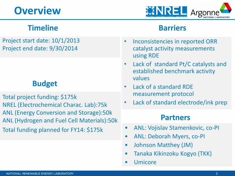
Overview
Project start date: 10/1/2013 Project end date: 9/30/2014
• Inconsistencies in reported ORR catalyst activity measurements using RDE
• Lack of standard Pt/C catalysts and established benchmark activity values
• Lack of a standard RDE measurement protocol
• Lack of standard electrode/ink prep Total project funding: $175k NREL (Electrochemical Charac. Lab):75k ANL (Energy Conversion and Storage):50k ANL (Hydrogen and Fuel Cell Materials):50k Total funding planned for FY14: $175k
Timeline
Budget
Barriers
• ANL: Vojislav Stamenkovic, co-PI • ANL: Deborah Myers, co-PI • Johnson Matthey (JM) • Tanaka Kikinzoku Kogyo (TKK) • Umicore
Partners

Relevance
4
Objectives
o To aid DOE in meeting goals for catalyst performance and durability by:- o Establishing protocols and best practices for ink dispersion/film
deposition/drying for rotating disk electrode (RDE) measurements to allow for more precise and reproducible data and reliable comparisons to be made by electrocatalyst development groups when evaluating novel synthesized catalysts in small quantities.

5
Background Several groups over the last few years reported discrepancies in activity values reported between research groups and also improvements in technique that allowed higher and more reproducible activity. CWG and DWG Meetings, Co-Chairs: Piotr Zelenay, Nancy Garland and Deborah Myers, Rod Borup, Honolulu, Hawaii, 2012; ECS, HNL meeting S. Kocha et al. 2012, ECS SF meeting, 2013; Garsany et al. & ECS SF meeting, 2013; Shinozaki et al. 2013.
DOE organized a webinar on RDE. Shyam S. Kocha, Yannick Garsany, Deborah Myers, Chair: Dimitrios Papageorgopoulos, 'Testing Oxygen Reduction Reaction Activity with the Rotating Disc Electrode Technique', March 12, 2013. http://www1.eere.energy.gov/hydrogenandfuelcells/pdfs/webinarslides_rde_technique_031213.pdf
DOE worked with NREL and ANL to issue a Request for Information (RFI) on best practices for RDE measurements for ORR activity
DOE funded AOPs for NREL and ANL to work on this project
DOE organized the Catalysis Working Group (CWG) meeting and Durability Working Group (DWG) meeting at NREL/DOE Field Office, December 2013, with one of the objectives being the discussion of responses to the RDE RFI.
6
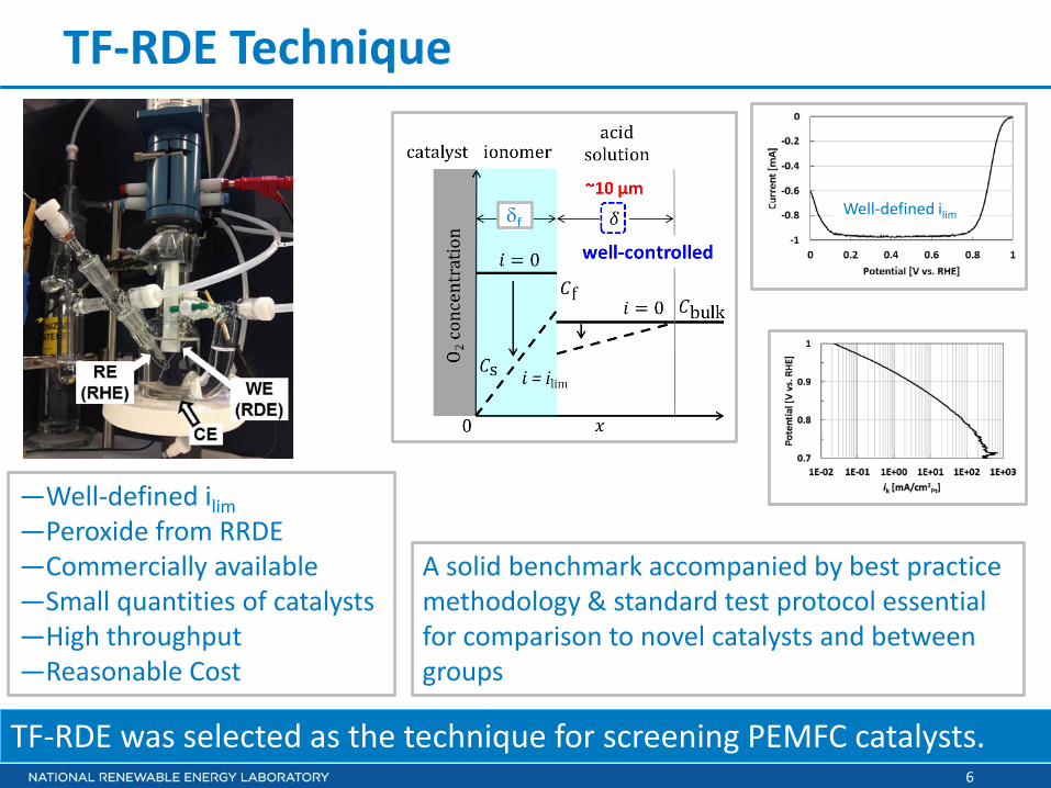
TF-RDE Technique
TF-RDE was selected as the technique for screening PEMFC catalysts.
—Well-defined ilim —Peroxide from RRDE —Commercially available —Small quantities of catalysts —High throughput —Reasonable Cost
A solid benchmark accompanied by best practice methodology & standard test protocol essential for comparison to novel catalysts and between groups
Well-defined ilim δf
7
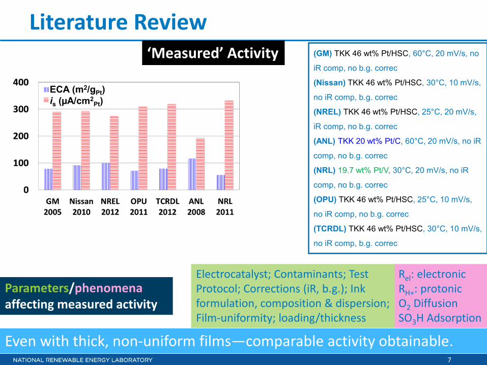
Literature Review
Even with thick, non-uniform films—comparable activity obtainable.
‘Measured’ Activity (GM) TKK 46 wt% Pt/HSC, 60°C, 20 mV/s, no
iR comp, no b.g. correc
(Nissan) TKK 46 wt% Pt/HSC, 30°C, 10 mV/s,
no iR comp, b.g. correc
(NREL) TKK 46 wt% Pt/HSC, 25°C, 20 mV/s,
iR comp, no b.g. correc
(ANL) TKK 20 wt% Pt/C, 60°C, 20 mV/s, no iR
comp, no b.g. correc
(NRL) 19.7 wt% Pt/V, 30°C, 20 mV/s, no iR
comp, no b.g. correc
(OPU) TKK 46 wt% Pt/HSC, 25°C, 10 mV/s,
no iR comp, no b.g. correc
(TCRDL) TKK 46 wt% Pt/HSC, 30°C, 10 mV/s,
no iR comp, b.g. correc
is (µA/cm2Pt)
ECA (m2/gPt)
Rel: electronic RH+: protonic O2 Diffusion SO3H Adsorption
Electrocatalyst; Contaminants; Test Protocol; Corrections (iR, b.g.); Ink formulation, composition & dispersion; Film-uniformity; loading/thickness
Parameters/phenomena affecting measured activity
8
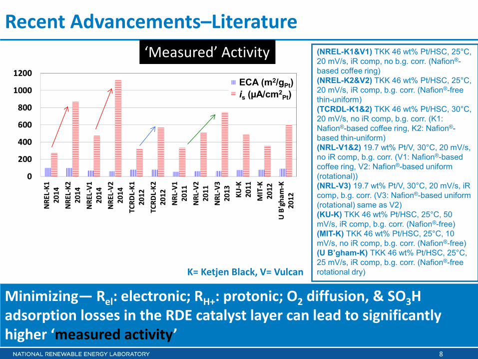
Recent Advancements–Literature
Minimizing— Rel: electronic; RH+: protonic; O2 diffusion, & SO3H adsorption losses in the RDE catalyst layer can lead to significantly higher ‘measured activity’
‘Measured’ Activity
is (µA/cm2Pt)
ECA (m2/gPt)
(NREL-K1&V1) TKK 46 wt% Pt/HSC, 25°C, 20 mV/s, iR comp, no b.g. corr. (Nafion®-based coffee ring) (NREL-K2&V2) TKK 46 wt% Pt/HSC, 25°C, 20 mV/s, iR comp, b.g. corr. (Nafion®-free thin-uniform) (TCRDL-K1&2) TKK 46 wt% Pt/HSC, 30°C, 20 mV/s, no iR comp, b.g. corr. (K1: Nafion®-based coffee ring, K2: Nafion®-based thin-uniform) (NRL-V1&2) 19.7 wt% Pt/V, 30°C, 20 mV/s, no iR comp, b.g. corr. (V1: Nafion®-based coffee ring, V2: Nafion®-based uniform (rotational)) (NRL-V3) 19.7 wt% Pt/V, 30°C, 20 mV/s, iR comp, b.g. corr. (V3: Nafion®-based uniform (rotational) same as V2) (KU-K) TKK 46 wt% Pt/HSC, 25°C, 50 mV/s, iR comp, b.g. corr. (Nafion®-free) (MIT-K) TKK 46 wt% Pt/HSC, 25°C, 10 mV/s, no iR comp, b.g. corr. (Nafion®-free) (U B’gham-K) TKK 46 wt% Pt/HSC, 25°C, 25 mV/s, iR comp, b.g. corr. (Nafion®-free rotational dry) K= Ketjen Black, V= Vulcan
Approach
10
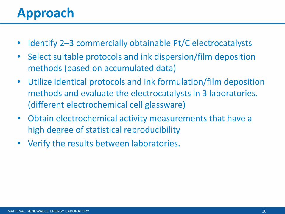
Approach
• Identify 2–3 commercially obtainable Pt/C electrocatalysts • Select suitable protocols and ink dispersion/film deposition
methods (based on accumulated data) • Utilize identical protocols and ink formulation/film deposition
methods and evaluate the electrocatalysts in 3 laboratories. (different electrochemical cell glassware)
• Obtain electrochemical activity measurements that have a high degree of statistical reproducibility
• Verify the results between laboratories.
11
CE
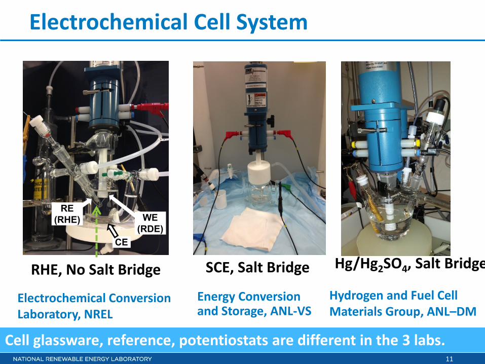
Electrochemical Cell System
RHE, No Salt Bridge
Electrochemical Conversion Laboratory, NREL
Energy Conversion and Storage, ANL-VS
SCE, Salt Bridge
Cell glassware, reference, potentiostats are different in the 3 labs.
Hydrogen and Fuel Cell Materials Group, ANL–DM
Hg/Hg2SO4, Salt Bridge
RE (RHE) WE
(RDE)
12
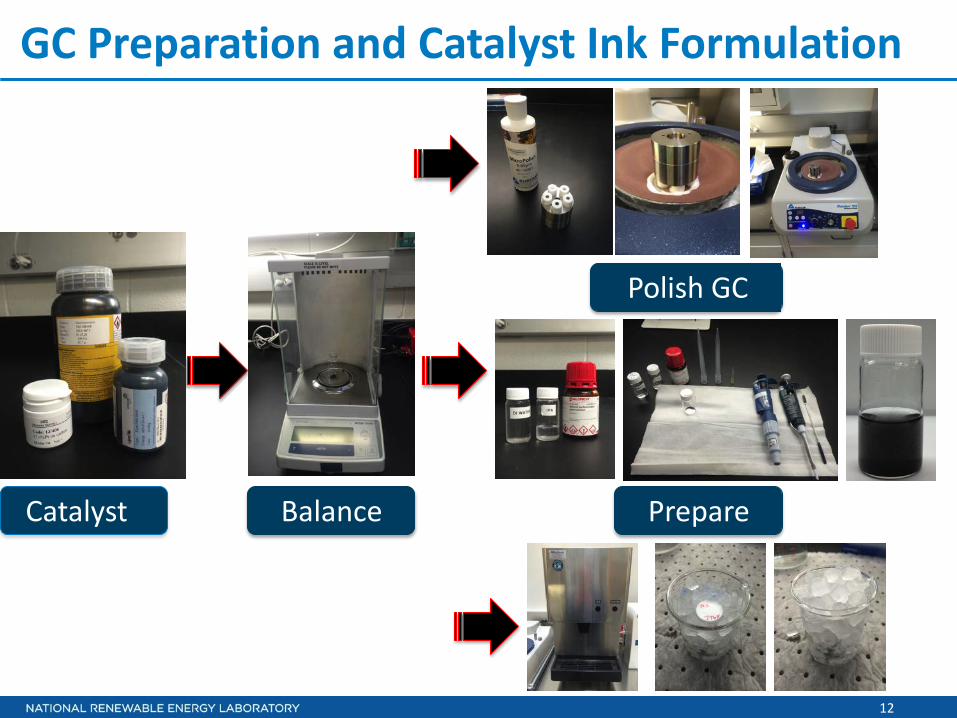
GC Preparation and Catalyst Ink Formulation
Catalyst Prepare Balance
Polish GC
13
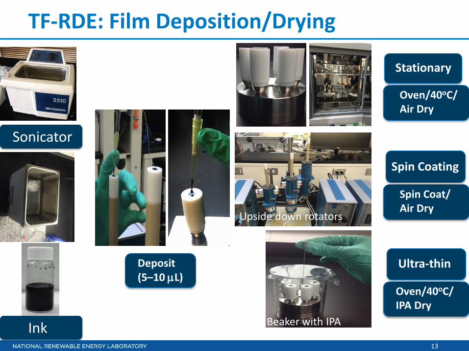
TF-RDE: Film Deposition/Drying
Beaker with IPA
Oven/40oC/ Air Dry
Deposit (5–10 µL)
Spin Coat/ Air Dry
Oven/40oC/ IPA Dry
Sonicator
Ink
Upside down rotators
Ultra-thin
Spin Coating
Stationary
14
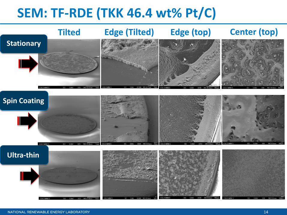
SEM: TF-RDE (TKK 46.4 wt% Pt/C)
Stationary
Spin Coating
Ultra-thin
Tilted Center (top) Edge (top) Edge (Tilted)

15
Impact of Method (TKK 46.4 wt% Pt/C)
15
Specific Activity (µA cm-2Pt)
ECA (m2g-1Pt)
Mass Activity (mA mg-1Pt)
Nafion-based uniform
Nafion-free thin-uniform
Nafion-based coffee-ring
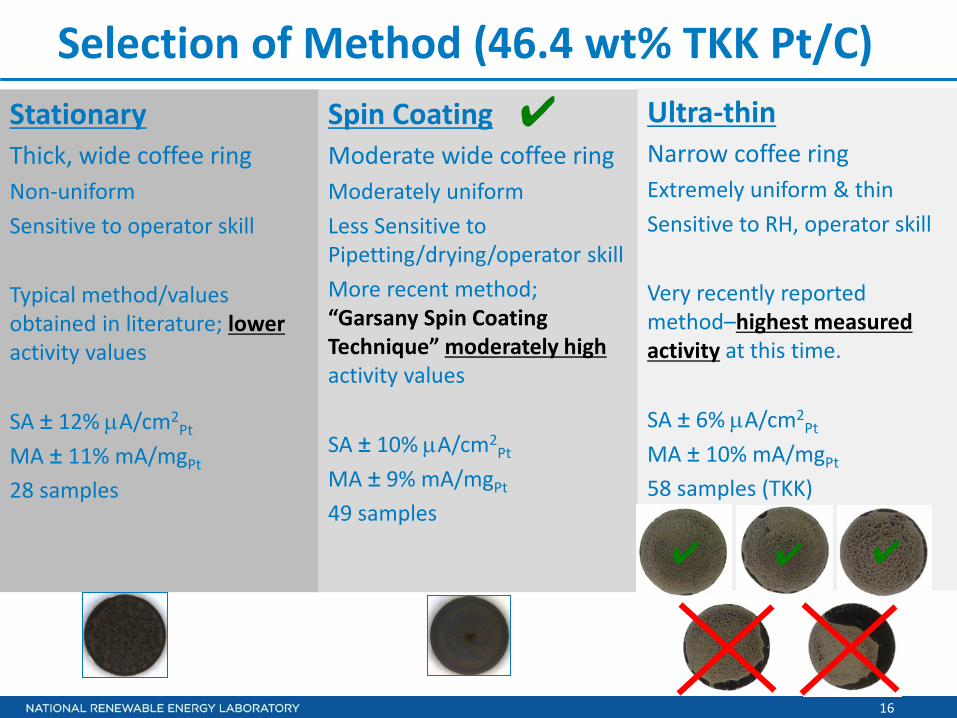
Spin coating selected since it is robust & not sensitive to operator skill.
✔
Stationary Spin Coating Ultra-thin
16
Selection of Method (46.4 wt% TKK Pt/C) Stationary Thick, wide coffee ring Non-uniform Sensitive to operator skill Typical method/values obtained in literature; lower activity values SA ± 12% µA/cm2
Pt MA ± 11% mA/mgPt 28 samples
Spin Coating Moderate wide coffee ring Moderately uniform Less Sensitive to Pipetting/drying/operator skill More recent method; “Garsany Spin Coating Technique” moderately high activity values SA ± 10% µA/cm2
Pt MA ± 9% mA/mgPt
49 samples
Ultra-thin Narrow coffee ring Extremely uniform & thin Sensitive to RH, operator skill Very recently reported method–highest measured activity at this time. SA ± 6% µA/cm2
Pt MA ± 10% mA/mgPt 58 samples (TKK)
✔ ✔ ✔
✔

Accomplishments & Progress
18
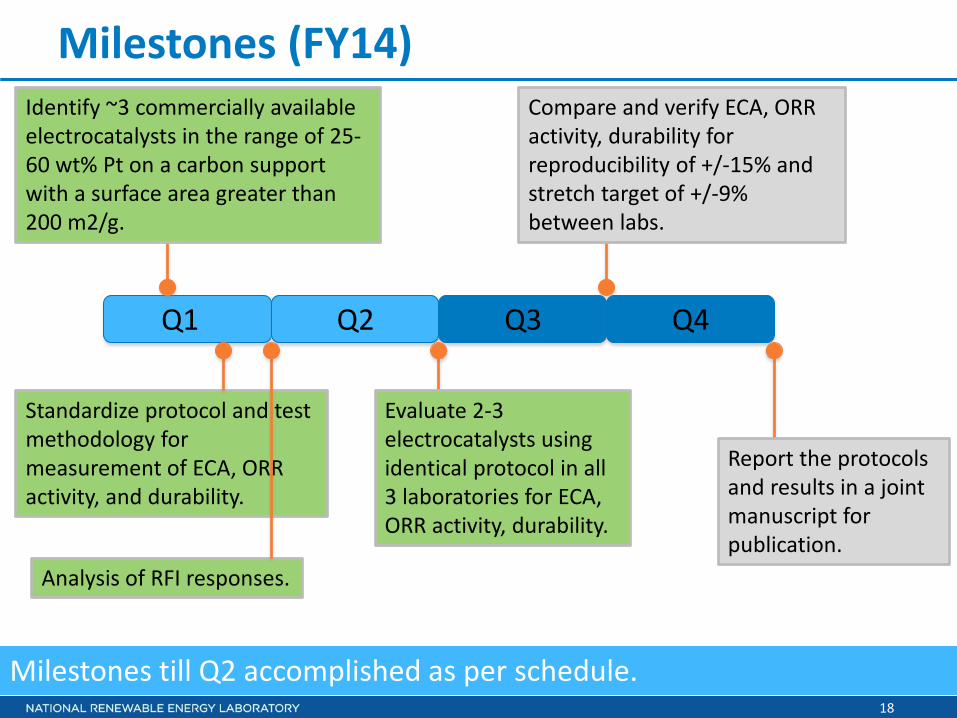
Milestones (FY14)
Milestones till Q2 accomplished as per schedule.
Identify ~3 commercially available electrocatalysts in the range of 25-60 wt% Pt on a carbon support with a surface area greater than 200 m2/g.
Analysis of RFI responses.
Standardize protocol and test methodology for measurement of ECA, ORR activity, and durability.
Q1 Q2 Q3 Q4
Evaluate 2-3 electrocatalysts using identical protocol in all 3 laboratories for ECA, ORR activity, durability.
Compare and verify ECA, ORR activity, durability for reproducibility of +/-15% and stretch target of +/-9% between labs.
Report the protocols and results in a joint manuscript for publication.

19
Summary RDE Test Protocol/Expt. Conditions
Corrections
1. iR compensation
2. Background Correction
3. Limiting current corrected to 100 kPa;
4. Kinetic currents corrected to 100 kPa using total reaction order for ORR of 0.85.
Measurement Protocols
1. Break-in: 0.025 – 1.2 V, 0.5 V/s, 100 cycles, N2
2. CV: 0.025 – 1.0 V, 0.02 V/s, 3 cycles, N2
3. IV: –0.01 → 1.0 V, 0.02 V/s, 1600 rpm, O2
Example Ink Formulation
(for 46.5 wt% Pt/C)
Pt/C : 7.6 mg
D.I. Water:7.6 ml
IPA: 2.4 ml
Sonication: Bath, ice, 20 min
Spin Coating: 700 rpm, ~ 15 min
Electrolyte: 0.1 M HClO4
Cell Temperature: Room Temperature

20
Choice of Protocol : Example–Scan Rate
Protocol selected after considerable data acquisition and analysis.
poly-Pt
0.1 M HClO4 r.t.
poly-Pt 0.1 M HClO4 r.t.
• Time required per experiment • Magnitude of b.g correction • Reproducibility
Impact of voltage range and scan direction also studied.
15 min/point
21
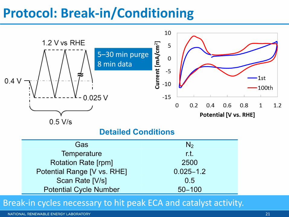
Protocol: Break-in/Conditioning
Break-in cycles necessary to hit peak ECA and catalyst activity.
Gas N2 Temperature r.t.
Rotation Rate [rpm] 2500 Potential Range [V vs. RHE] 0.025‒1.2
Scan Rate [V/s] 0.5 Potential Cycle Number 50‒100
Detailed Conditions
5–30 min purge 8 min data

22
Protocol: CV under N2
HUPD area from cyclic voltammogram used to determine ECA.
Detailed Conditions Gas N2
Temperature r.t. Rotation Rate [rpm] 0
Potential Range [V vs. RHE] 0.025‒1.0 Scan Rate [V/s] 0.02
Potential Cycle Number 3 Scan type Linear (Analog)
ECA Estimation Method Hads charge
ECA estimation
Pt + H+ +e− → Pt−H
~5 min data
23
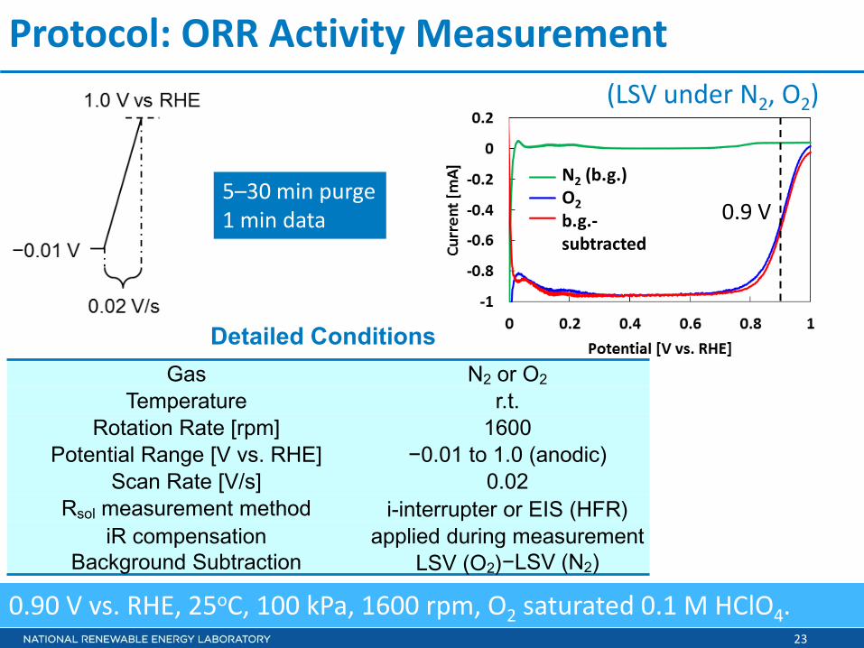
Protocol: ORR Activity Measurement
0.90 V vs. RHE, 25oC, 100 kPa, 1600 rpm, O2 saturated 0.1 M HClO4.
Detailed Conditions Gas N2 or O2
Temperature r.t. Rotation Rate [rpm] 1600
Potential Range [V vs. RHE] −0.01 to 1.0 (anodic) Scan Rate [V/s] 0.02
Rsol measurement method i-interrupter or EIS (HFR) iR compensation applied during measurement
Background Subtraction LSV (O2)−LSV (N2)
(LSV under N2, O2)
0.9 V
N2 (b.g.) O2 b.g.- subtracted
5–30 min purge 1 min data
24
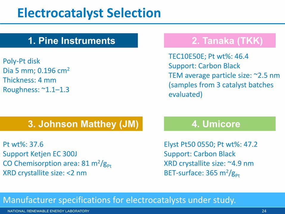
Electrocatalyst Selection
2. Tanaka (TKK)
3. Johnson Matthey (JM) 4. Umicore
Manufacturer specifications for electrocatalysts under study.
Pt wt%: 37.6 Support Ketjen EC 300J CO Chemisorption area: 81 m2/gPt XRD crystallite size: <2 nm
1. Pine Instruments TEC10E50E; Pt wt%: 46.4 Support: Carbon Black TEM average particle size: ~2.5 nm (samples from 3 catalyst batches evaluated)
Elyst Pt50 0550; Pt wt%: 47.2 Support: Carbon Black XRD crystallite size: ~4.9 nm BET-surface: 365 m2/gPt
Poly-Pt disk Dia 5 mm; 0.196 cm2
Thickness: 4 mm Roughness: ~1.1–1.3

25
Cell Cleanliness & Perchloric Acid Source
Concentrated Acid Soak Boiling in DI water/change water x6
Sources of Perchloric Acid Rigorous cleaning of glassware and choice of perchloric acid is critical.
Veritas® Doubly Distilled (GFS chemicals)Omni Trace Ultra (EMD Millipore)J.T. Baker® ULTREX II Ultrapure (AVANTOR)TraceSELECT® (Sigma-Aldrich)Suprapur® (Merck)Superior ACS (GFS chemicals)trace metal basis (Sigma-Aldrich)ACS (Sigma-Aldrich) ✗
✔
✔ ✔
26
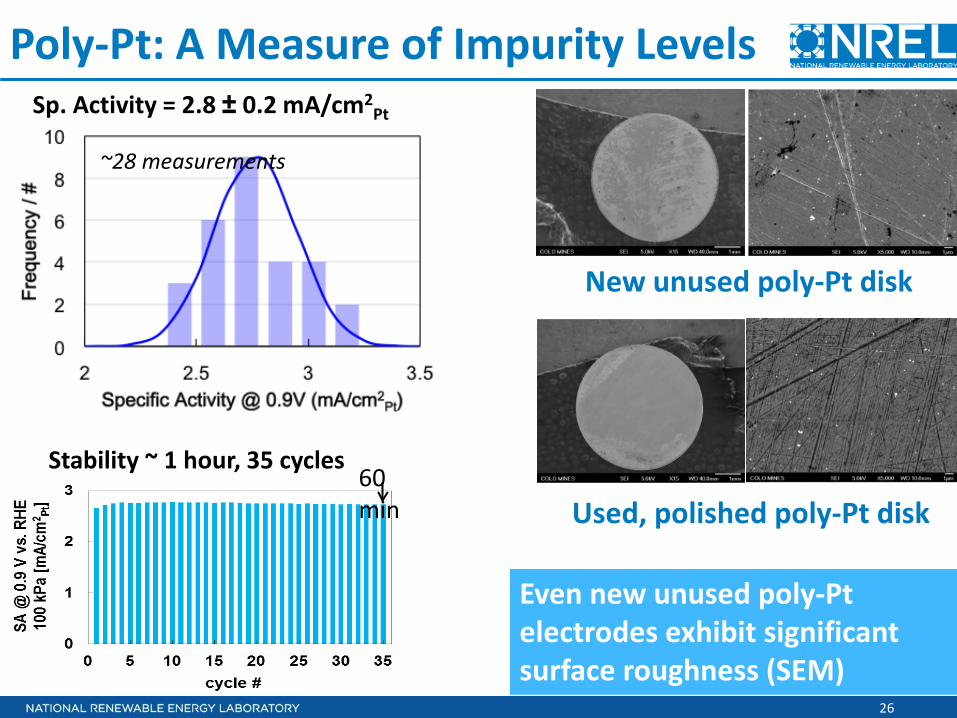
Poly-Pt: A Measure of Impurity Levels Sp. Activity = 2.8 ± 0.2 mA/cm2
Pt
Stability ~ 1 hour, 35 cycles
~28 measurements
60 min
New unused poly-Pt disk
Used, polished poly-Pt disk
Even new unused poly-Pt electrodes exhibit significant surface roughness (SEM)
27
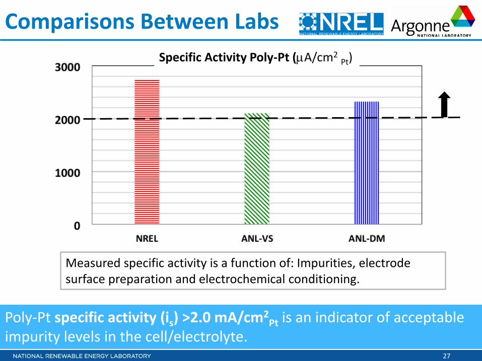
Comparisons Between Labs Specific Activity Poly-Pt (µA/cm2 Pt)
Measured specific activity is a function of: Impurities, electrode surface preparation and electrochemical conditioning.
Poly-Pt specific activity (is) >2.0 mA/cm2Pt is an indicator of acceptable
impurity levels in the cell/electrolyte.

28
Specific Activity (µA cm-2Pt)
ECA (m2g-1Pt)
Mass Activity (mA mg-1Pt)
TKK JM Umicore
485 ± 10% (n = 49) 515 ± 5% (n = 29) 344 ± 8% (n = 24)
ECA, specific and mass activity for 3 Pt/C electrocatalysts @ NREL
Catalyst Evaluation: Spin Coating
TKK JM Umicore
46.4 wt% Pt; d~2.5nm 37.6 wt% Pt; d<2nm 47.2 wt% Pt; d~4.9nm
29
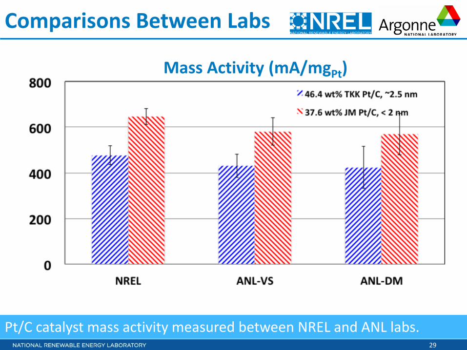
Comparisons Between Labs
Pt/C catalyst mass activity measured between NREL and ANL labs.
Mass Activity (mA/mgPt)

30
Collaborations Institutions Role
National Renewable Energy Laboratory (NREL): Shyam Kocha (PI), Jason Zack, Kazuma Shinozaki, Svetlana Pylypenko
Prime, oversees the project, selection of catalysts, investigation of protocols, ink dispersion, ink formulation and film deposition
Argonne National Laboratory (ANL): Energy Conversion and Storage Group Vojislav Stamenkovic (co-PI), Yijin Kang, Joshua Snyder
Participate as co-PI in selection of catalysts, protocols, & perform catalyst evaluation
Argonne National Laboratory (ANL): Hydrogen and Fuel Cell Materials Group Deborah Myers (co-PI), Nancy Kariuki, Tammi Nowicki
Participate as co-PI in selection of catalysts, protocols, & perform catalyst evaluation
Johnson Matthey (JM, UK) Provide electrocatalysts, dry catalyst characterization
Tanaka Kikinzoku Kyogyo (TKK, Japan) Provide electrocatalysts, dry catalyst characterization
Umicore (Germany) Provide electrocatalysts, dry catalyst characterization
University of the Western Cape & HySA (S. Africa): Bruno Pollet Naval Research Laboratory (NRL): Yannick Garsany Discuss/consult on RDE test methodology
Interactions: Discussions with Catalysis Working Group & feedback from DOE RDE RFI responses

31
Proposed Future Work • Plans for the remainder of FY14
o Come up with and agree on a strategy on the logistics of distributing/shipping ~1g of electrocatalyst material (no charge) to those groups that are awarded a new electrocatalyst related project in upcoming DOE FOAs over the next ~5 years. [100 g of each catalyst available.]
o Disseminate the results of the study (best practices for RDE and benchmark activity values) so that it is accessible to the PEM fuel cell electrocatalysis scientific community.
• Plans for the next year (FY 15) o We recommend a second phase of this study, where we evaluate
easily available Pt-alloy/C catalysts, Pt/alternative carbon support catalysts to establish the status of these materials versus the baseline Pt/C materials. We also recommend an RDE durability study of these electrocatalyst materials.
32
Summary
• Relevance: Establish protocols and best practices for ink dispersion/film deposition/drying for rotating disk electrode (RDE) measurements to allow for more precise and reproducible data and reliable comparisons to be made between electrocatalyst development groups.
• Approach: To obtain electrocatalytic activity measurements: – for 2–3 commercially obtainable Pt/C electrocatalysts – for which the activity is measured a high degree of statistical reproducibility – using the same protocol and ink formulation and having the catalysts tested in 3 laboratories.
• Accomplishments and Progress: – Poly-Pt and 3 Pt/C nanoparticle electrocatalysts from major manufacturers were selected – A test protocol based on extensive study was selected – Cell cleaning, a variety of perchloric acid from different sources and the use of poly-Pt as
cleanliness sensor was established – Of the various ink formulations/dispersion methods/coating and drying methods, the spin
coating method was selected. – Poly-Pt, TKK and JM catalysts were evaluated to obtain activity and standard deviation values
and are reported.
• Collaborations: 2 US national labs, 3 PEMFC industry catalyst vendors, Naval Research Labs and University of the Western Cape/HySA
• Proposed Future Research: Disseminate the results of the study (best practices for RDE and benchmark activity values) so that it is accessible to the PEM fuel cell electrocatalysis scientific community.

33
END

Technical Back-Up Slides
35
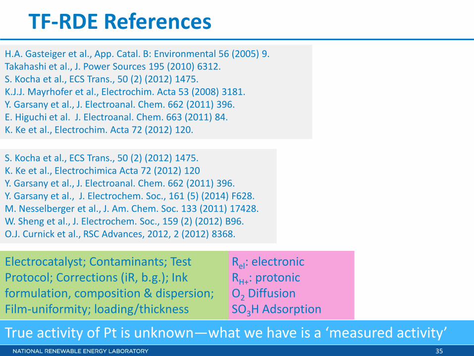
TF-RDE References
True activity of Pt is unknown—what we have is a ‘measured activity’
H.A. Gasteiger et al., App. Catal. B: Environmental 56 (2005) 9. Takahashi et al., J. Power Sources 195 (2010) 6312. S. Kocha et al., ECS Trans., 50 (2) (2012) 1475. K.J.J. Mayrhofer et al., Electrochim. Acta 53 (2008) 3181. Y. Garsany et al., J. Electroanal. Chem. 662 (2011) 396. E. Higuchi et al. J. Electroanal. Chem. 663 (2011) 84. K. Ke et al., Electrochim. Acta 72 (2012) 120.
S. Kocha et al., ECS Trans., 50 (2) (2012) 1475. K. Ke et al., Electrochimica Acta 72 (2012) 120 Y. Garsany et al., J. Electroanal. Chem. 662 (2011) 396. Y. Garsany et al., J. Electrochem. Soc., 161 (5) (2014) F628. M. Nesselberger et al., J. Am. Chem. Soc. 133 (2011) 17428. W. Sheng et al., J. Electrochem. Soc., 159 (2) (2012) B96. O.J. Curnick et al., RSC Advances, 2012, 2 (2012) 8368.
Rel: electronic RH+: protonic O2 Diffusion SO3H Adsorption
Electrocatalyst; Contaminants; Test Protocol; Corrections (iR, b.g.); Ink formulation, composition & dispersion; Film-uniformity; loading/thickness
36
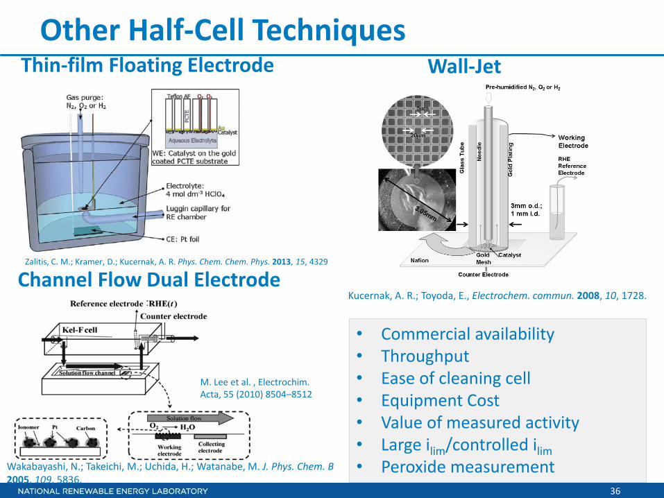
Other Half-Cell Techniques
Channel Flow Dual Electrode
Wall-Jet Thin-film Floating Electrode
• Commercial availability • Throughput • Ease of cleaning cell • Equipment Cost • Value of measured activity • Large ilim/controlled ilim • Peroxide measurement
M. Lee et al. , Electrochim. Acta, 55 (2010) 8504–8512
Zalitis, C. M.; Kramer, D.; Kucernak, A. R. Phys. Chem. Chem. Phys. 2013, 15, 4329
Kucernak, A. R.; Toyoda, E., Electrochem. commun. 2008, 10, 1728.
Wakabayashi, N.; Takeichi, M.; Uchida, H.; Watanabe, M. J. Phys. Chem. B 2005, 109, 5836.

37
• Oxygen Flow : Oxygen Saturated Acid Disk Rotation
• Pt/C | Nafion : Pt/C |Nafion | Acid • Gas, H2O, pores : Acid Flooded pores • Electrode Thickness (~10 µm) : (0.3–4 µm) • 100 % RH : Liquid Acid Electrolyte • 15 min/point: Scan Rate:20 mV/s
Electrocatalyst on Support MEAs of PEMFCs Thin-film RDE
MEA vs. RDE: Materials, Structure, Mass-trans
Trends of catalyst activity and durability in RDE studies can be used to predict trends in PEMFCs
Thick film Patchy film No ionomer HClO4
Ionomer