best practices in dam and levee safety risk analysis · · 2015-06-26best practices in dam and...
TRANSCRIPT

Best Practices in Dam and Levee Safety Risk Analysis V-1. Reinforced Concrete Failure Mechanisms
22 April 2015
Chapter V-1 presents the failure mechanisms of reinforced concrete sections such as spillway piers, walls, slabs, and buttresses. factors influencing the strength and stability of the reinforced
concrete sections
how to consider National code requirements in the context of risk
considerations when determining risk analysis failure probabilities based on structural analysis results
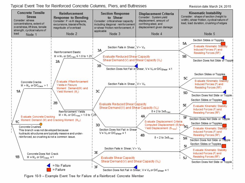
a typical event tree of the progression of failure
Introduction

Geometry and support conditions of the section Material properties of the reinforcement
Material properties of the concrete
Amount and detailing of the reinforcement
Type and duration of loading
Location of the reinforced concrete members relative to the entire structure
Factors Influencing the Strength and Stability of Reinforced Concrete Sections
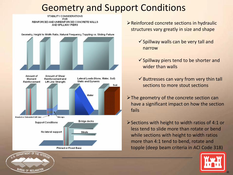
Reinforced concrete sections in hydraulic structures vary greatly in size and shape Spillway walls can be very tall and
narrow Spillway piers tend to be shorter and
wider than walls Buttresses can vary from very thin tall
sections to more stout sections The geometry of the concrete section can
have a significant impact on how the section fails Sections with height to width ratios of 4:1 or
less tend to slide more than rotate or bend while sections with height to width ratios more than 4:1 tend to bend, rotate and topple (deep beam criteria in ACI Code 318)
Geometry and Support Conditions

Glen Canyon Dam Spillway Gate Piers Canyon Ferry Dam Spillway Gate Piers
Geometry and Support Conditions - Piers
Minidoka Dam Canal Headworks Gate Piers
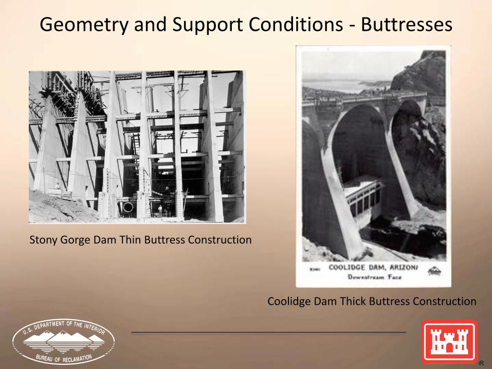
Stony Gorge Dam Thin Buttress Construction
Coolidge Dam Thick Buttress Construction
Geometry and Support Conditions - Buttresses

Glendo Dam Chute Walls Stampede Dam Stilling Basin
Geometry and Support Conditions - Spillways
Stampede Dam Inlet Control Structure
Examples typically not considered a reinforced concrete PFM Generally only
consider gated spillway crest structure However failure
could contribute to another PFM
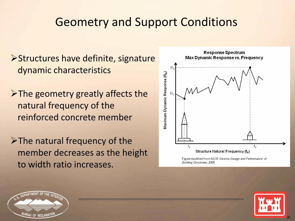
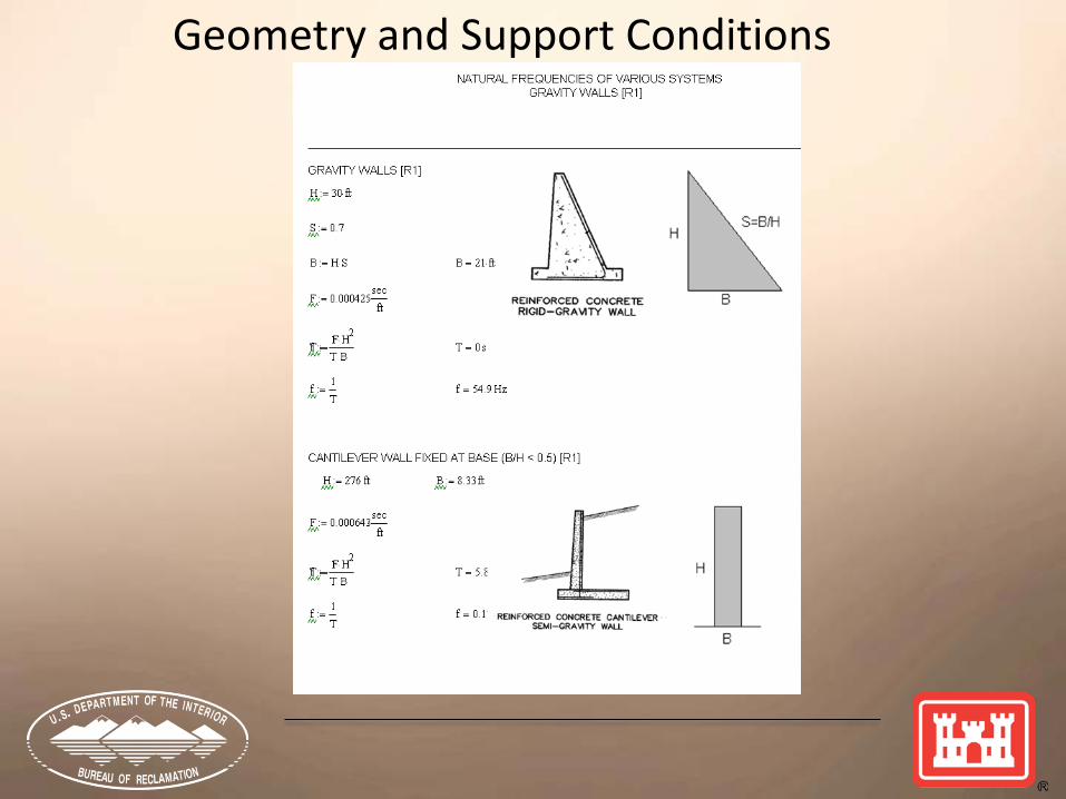
Structures have definite, signature dynamic characteristics The geometry greatly affects the
natural frequency of the reinforced concrete member
The natural frequency of the
member decreases as the height to width ratio increases.
Geometry and Support Conditions
Geometry and Support Conditions

Geometry and Support Conditions
Structural response to seismic loading will be different for sections: on rock foundations compared to soil foundations
founded on the top of a dam where ground motions are
generally amplified
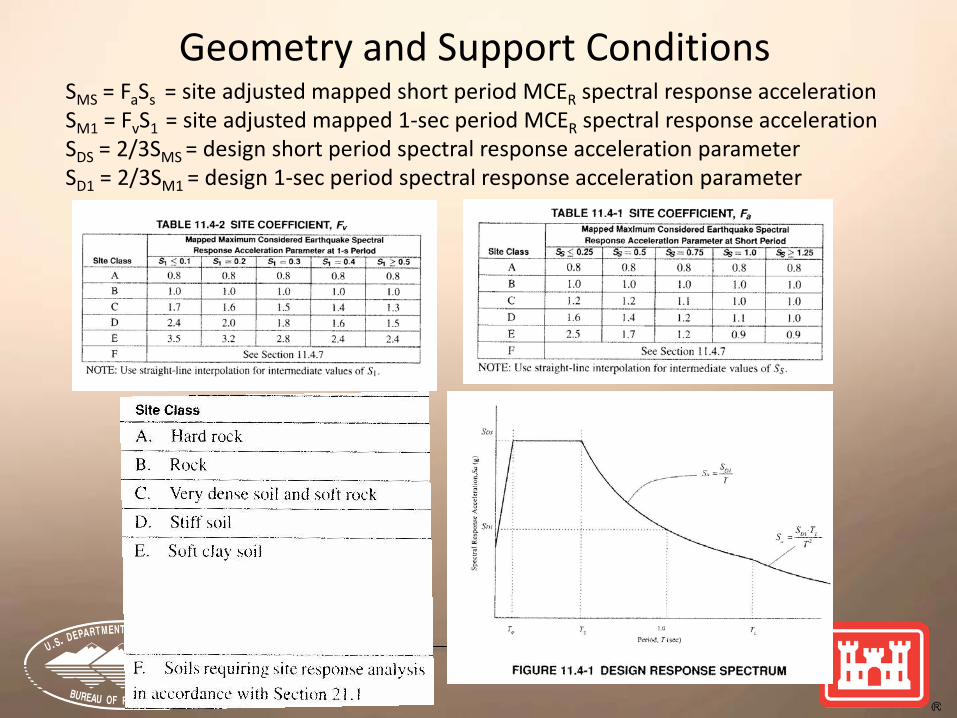
Geometry and Support Conditions SMS = FaSs = site adjusted mapped short period MCER spectral response acceleration SM1 = FvS1 = site adjusted mapped 1-sec period MCER spectral response acceleration SDS = 2/3SMS = design short period spectral response acceleration parameter SD1 = 2/3SM1 = design 1-sec period spectral response acceleration parameter
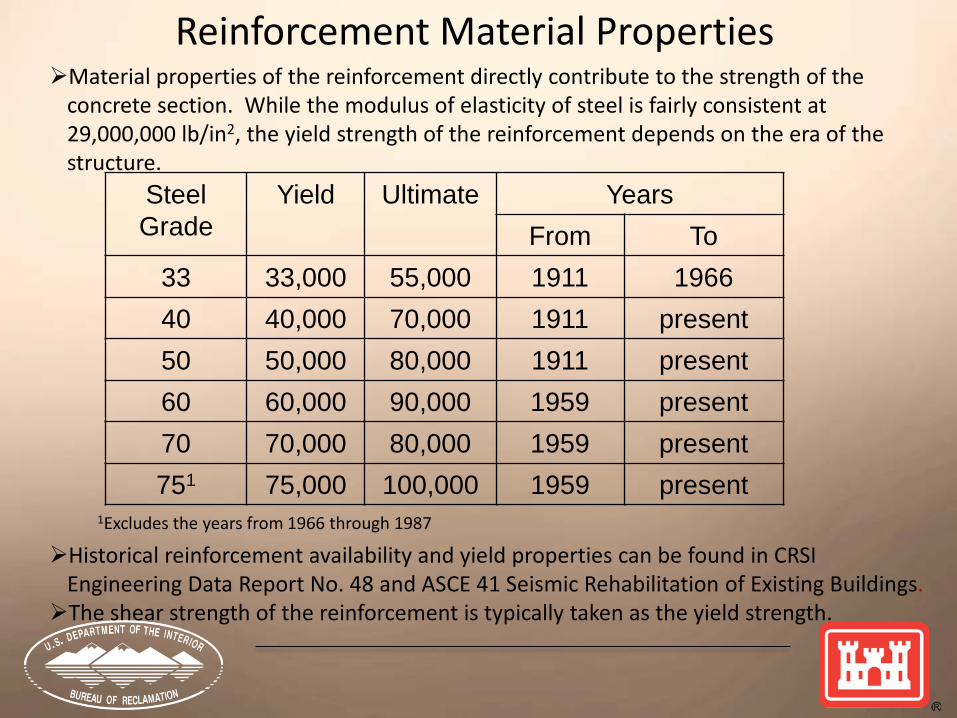
Material properties of the reinforcement directly contribute to the strength of the concrete section. While the modulus of elasticity of steel is fairly consistent at 29,000,000 lb/in2, the yield strength of the reinforcement depends on the era of the structure.
1Excludes the years from 1966 through 1987
Historical reinforcement availability and yield properties can be found in CRSI Engineering Data Report No. 48 and ASCE 41 Seismic Rehabilitation of Existing Buildings. The shear strength of the reinforcement is typically taken as the yield strength.
Steel Grade
Yield Ultimate Years From To
33 33,000 55,000 1911 1966 40 40,000 70,000 1911 present 50 50,000 80,000 1911 present 60 60,000 90,000 1959 present 70 70,000 80,000 1959 present 751 75,000 100,000 1959 present
Reinforcement Material Properties
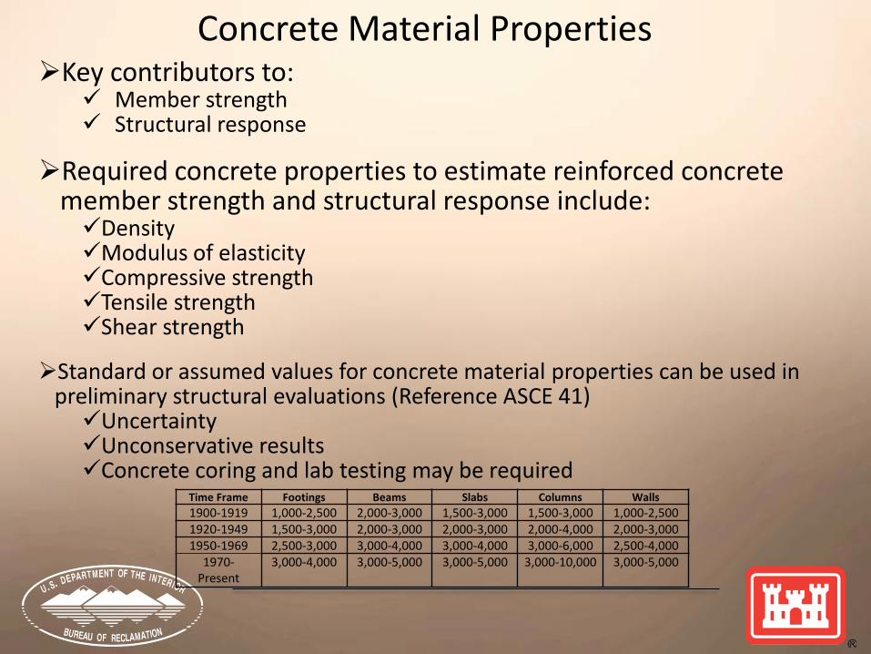
Key contributors to: Member strength Structural response
Required concrete properties to estimate reinforced concrete
member strength and structural response include: Density Modulus of elasticity Compressive strength Tensile strength Shear strength
Standard or assumed values for concrete material properties can be used in
preliminary structural evaluations (Reference ASCE 41) Uncertainty Unconservative results Concrete coring and lab testing may be required
Concrete Material Properties
Time Frame Footings Beams Slabs Columns Walls 1900-1919 1,000-2,500 2,000-3,000 1,500-3,000 1,500-3,000 1,000-2,500 1920-1949 1,500-3,000 2,000-3,000 2,000-3,000 2,000-4,000 2,000-3,000 1950-1969 2,500-3,000 3,000-4,000 3,000-4,000 3,000-6,000 2,500-4,000
1970-Present
3,000-4,000 3,000-5,000 3,000-5,000 3,000-10,000 3,000-5,000
Concrete Material Properties
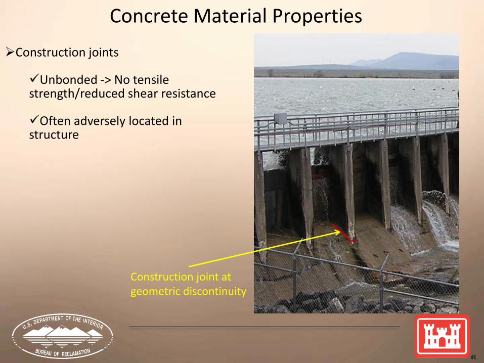
Construction joint at geometric discontinuity
Construction joints Unbonded -> No tensile strength/reduced shear resistance
Often adversely located in structure
Ductile vs. brittle failures Ductile failure much better than brittle failures Ductile failures occur much slower than brittle failures Ductile failures provide evidence of structural distress prior to failure Ductile failures allows time for repair or evacuation prior to failure Shear failures tend to be more sudden than ductile type bending or
tensile failures Ductile sections
Require reinforcement design details per ACI code Detailing examples
stirrups will confine areas of damaged concrete and help maintain post-seismic structural integrity As(min) = 200bwd/fy Shear strength based exclusively on Vc is okay provided As≥As(min) and ρ≤0.75ρb
Reinforcement Details

Older hydraulic structures were not designed for current seismic loads
Seismic detailing requirements have changed dramatically over the last several decades
Insufficient embedment lengths, splice lengths or hook details can result in sudden pullout failures
Massive hydraulic structures are typically lightly or under-reinforced and can be greatly overstressed by large earthquakes and can yield and deflect excessively
Reinforcement Details

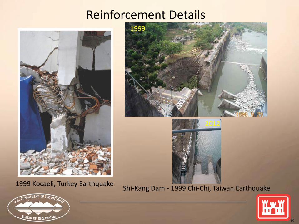
Reinforcement Details 1999 Kocaeli, Turkey Earthquake
Embedment/Splice Lengths
Reinforcement Details
1999 Kocaeli, Turkey Earthquake Shi-Kang Dam - 1999 Chi-Chi, Taiwan Earthquake
1999
2012
Static loads Examples - hydrostatic or soil pressures Typically act for long durations - sustained loads There may be no mechanism to stop or resist a section in the process
of failing if the static loads exceed the capacity of the structure Earthquake loads
are cyclical and change direction rapidly sections may not crack through the member thickness even though the
tensile capacity is exceeded for short durations the seismic load may not have sufficient duration or have enough
significant stress peaks to completely strain a section to failure as the member cracks and changes frequency, the response of the
structure may change the seismic loads and failure potential Post-seismic stability must consider the ability of a damaged section to
carry static loads
Type and Duration of Load

One stress spike
One stress spike
Type and Load Duration
Expected Nominal Capacity
Structural System Considerations
Structural systems that perform well during earthquakes Dissipate energy through inelastic deformation Alter dynamic properties (period shift) Mobilize additional strength elsewhere in the system (highly
redundant)
Hydraulic structures are generally not highly redundant However, retaining walls have historically performed very well
during earthquakes Seismic loads extend beyond performance database
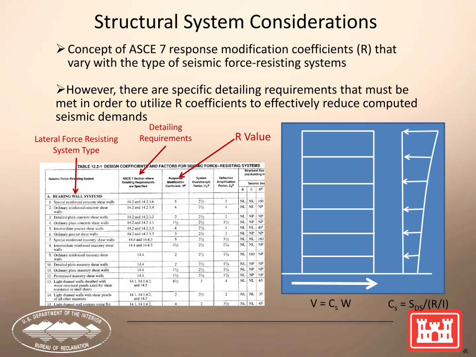
Structural System Considerations Concept of ASCE 7 response modification coefficients (R) that
vary with the type of seismic force-resisting systems However, there are specific detailing requirements that must be met in order to utilize R coefficients to effectively reduce computed seismic demands
V = Cs W Cs = SDS/(R/I)
R Value Lateral Force Resisting System Type
Detailing Requirements
When evaluating D/C ratios, it is important to evaluate values representative of the structure as a whole and not just localized maxima
A progressive failure may occur if a localized area is overstressed, but this will take time under multiple earthquake peaks if there is potential for load redistribution
Displacement criteria should be used to evaluate inelastic behavior of reinforced concrete members
Biggest challenge for RA team Severe damage may result from many cycles of demand exceeding
capacity The remaining strength of the damaged section is primarily a
judgment call of the RA team
Analysis Results Considerations
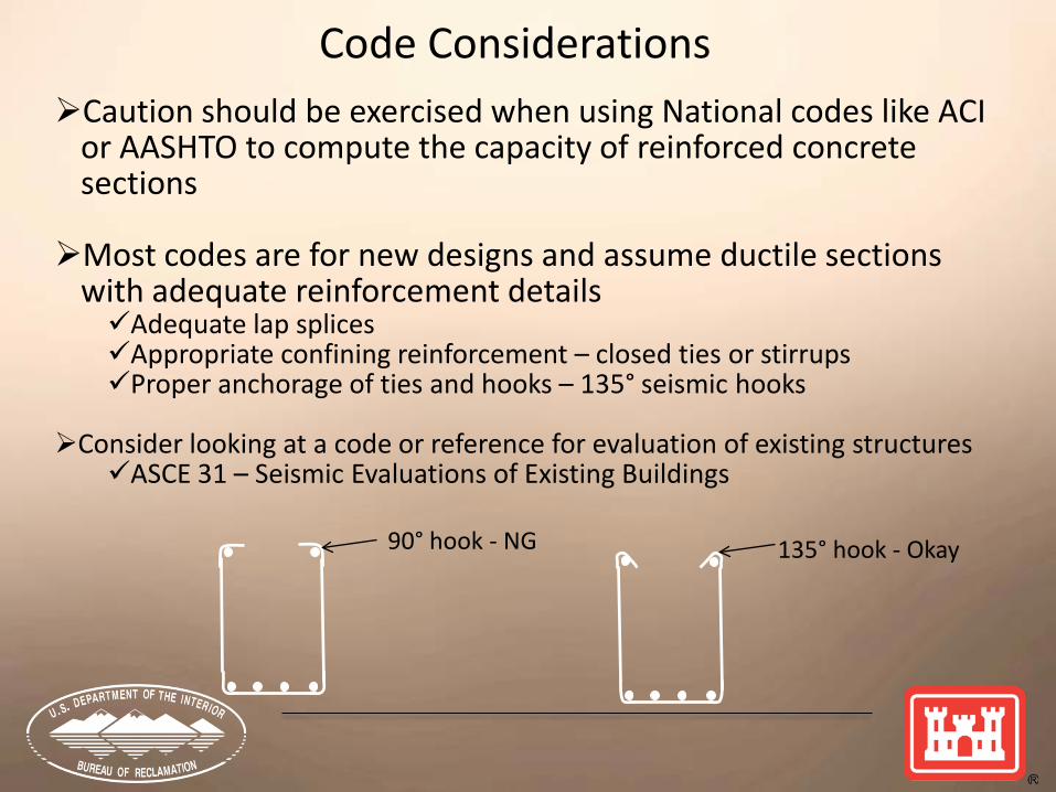
Caution should be exercised when using National codes like ACI or AASHTO to compute the capacity of reinforced concrete sections
Most codes are for new designs and assume ductile sections
with adequate reinforcement details Adequate lap splices Appropriate confining reinforcement – closed ties or stirrups Proper anchorage of ties and hooks – 135° seismic hooks
Consider looking at a code or reference for evaluation of existing structures ASCE 31 – Seismic Evaluations of Existing Buildings
Code Considerations
90° hook - NG 135° hook - Okay

Load factors and strength reduction (φ) factors
Used for new designs to Address analysis and design uncertainties and assumptions (LF) Account for variations in materials (φ) Account for variations in construction (φ) Generally build-in factors of safety
Do not apply for risk analyses of existing reinforced concrete structures
Compute the demand or load on the section without load factors Compute the “true” or “expected” capacity of the section without φ
During the risk analyses team members should consider: The condition of the concrete and reinforcement Severity of the environment Deterioration due to alkali-aggregate reaction Evidence of freeze-thaw deterioration Evidence of corrosion
Code Considerations
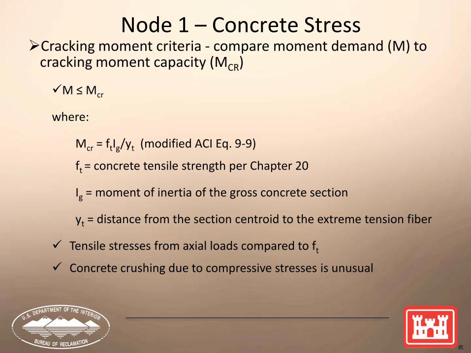
Node 1 – Concrete Stress Cracking moment criteria - compare moment demand (M) to
cracking moment capacity (MCR)
M ≤ Mcr
where: Mcr = ftIg/yt (modified ACI Eq. 9-9) ft = concrete tensile strength per Chapter 20 Ig = moment of inertia of the gross concrete section yt = distance from the section centroid to the extreme tension fiber
Tensile stresses from axial loads compared to ft
Concrete crushing due to compressive stresses is unusual
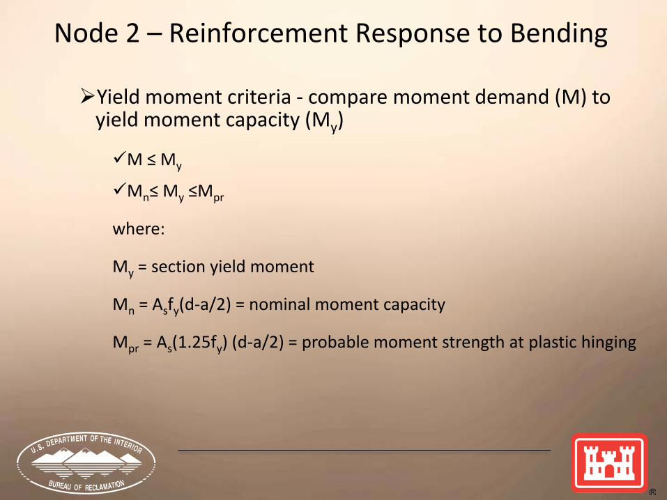
Node 2 – Reinforcement Response to Bending
Yield moment criteria - compare moment demand (M) to yield moment capacity (My)
M ≤ My Mn≤ My ≤Mpr
where:
My = section yield moment Mn = Asfy(d-a/2) = nominal moment capacity Mpr = As(1.25fy) (d-a/2) = probable moment strength at plastic hinging

Node 2 – Reinforcement Response to Bending

Node 2 – Reinforcement Response to Bending
spColumn – interaction diagrams for member subjected to both axial load and flexure

Node 3 - Section Response to Shear
Response curve more representative of lightly or unreinforced sections - shear reinforcement will add ductility
For slender members (>4H:1W) Vn = Vc + Vs
• Vc = concrete shear strength
• Vs = reinforcement shear strength
Shear friction reinforcement
Need to consider type of shear failure when evaluating shear capacity – diagonal crack or horizontal crack
Should be supplemental to primary flexural reinforcement
Shear System Response (Moment Reinforcement Has or Has Not Yielded)
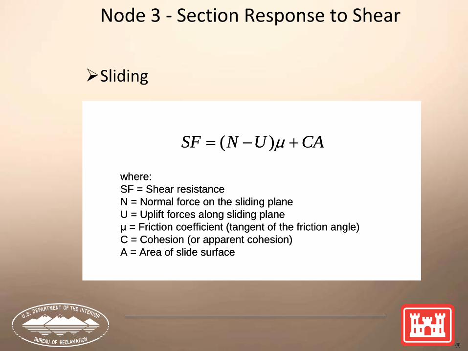
CAUNSF +−= µ)(
where:SF = Shear resistanceN = Normal force on the sliding planeU = Uplift forces along sliding planeμ = Friction coefficient (tangent of the friction angle)C = Cohesion (or apparent cohesion)A = Area of slide surface
CAUNSF +−= µ)(
where:SF = Shear resistanceN = Normal force on the sliding planeU = Uplift forces along sliding planeμ = Friction coefficient (tangent of the friction angle)C = Cohesion (or apparent cohesion)A = Area of slide surface
Node 3 - Section Response to Shear
Sliding
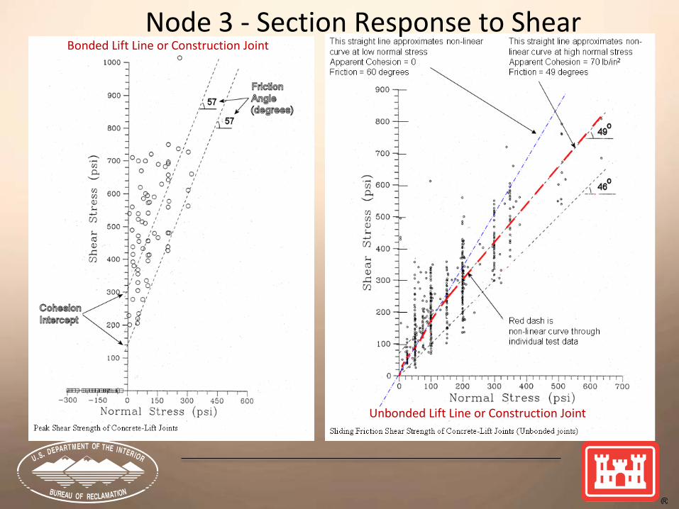
Node 3 - Section Response to Shear Bonded Lift Line or Construction Joint
Unbonded Lift Line or Construction Joint
Node 4 - Displacement Criteria
Based on research at the University of Illinois at Champagne-Urbana by Mete Sozen
Considers nonlinear behavior of section within structural system
Determine nonlinear displacements in reinforced concrete system
Structure may be viable if: δ / δyield ≤ 2 to 3

δyield calculation Straightforward – constant E
Actual yield deflections will likely be larger since moment of inertia will be that for a cracked section (method is conservative)
δ calculation Not so easy – variable E
Non-linear FEA most accurate approach
Simplified approach use ⅓ to ½ Ec
System secondary (P-δ) analysis
Node 4 - Displacement Criteria
constant E
variable E
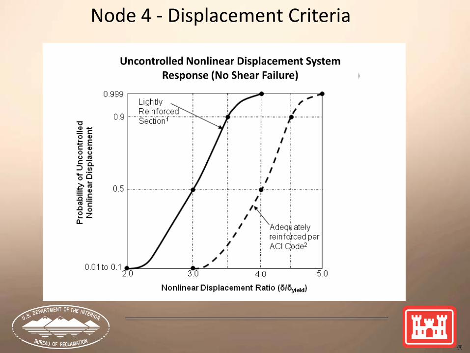
Node 4 - Displacement Criteria
Uncontrolled Nonlinear Displacement System Response (No Shear Failure)
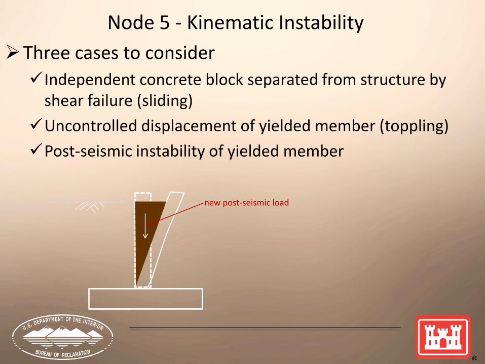
Node 5 - Kinematic Instability Three cases to consider Independent concrete block separated from structure by
shear failure (sliding) Uncontrolled displacement of yielded member (toppling) Post-seismic instability of yielded member
new post-seismic load